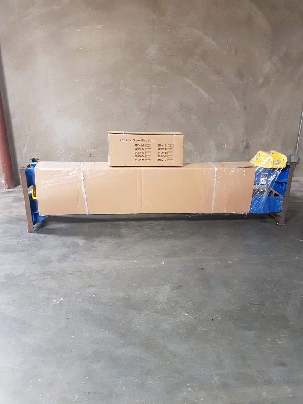
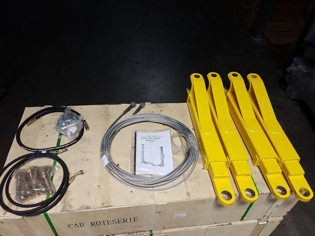
9,000 POUND TWO-COLUMN AUTOMOTIVE LIFT Model: NW-2-9KFP MANUAL
|
|
|
- Jeremy McCarthy
- 5 years ago
- Views:
Transcription

1 9,000 POUND TWO-COLUMN AUTOMOTIVE LIFT Model: NW-2-9KFP MANUAL 1
2 9,000 POUND CAPACITY MODEL: NW-2-9KFP TWO-COLUMN AUTOMOTIVE LIFT READ THIS ENTIRE MANUAL BEFORE OPERATION BEGINS RECORD BELOW THE FOLLOWING INFORMATION WHICH IS LOCATED ON THE SERIAL NUMBER DATA PLATE Serial No. Model No. Date of Install RECORD BELOW THE FOLLOWING CUSTOMER INFORMATION Company Name Contact Person * Street Address City State Phone Fax * *Optional Fields NOTE: To validate warranty, this information must be copied and either faxed or mailed to: Nationwide Rio Nedo Temecula, CA
3 IMPORTANT INFORMATION Two Post Lifts 1. Any freight damage must be noted on the freight bill before signing and reported to the freight carrier with a freight claim established. Identify the components and check for shortages. If shortages are discovered, please contact the Distributor / Sales Rep. in your area for service. 2. Consult building owner and / or architect s plans when applicable to establish the best lift location. The lift should be located on a relatively level floor with 4 in. minimum thickness, 3000-psi concrete slab that has been properly cured. There can be no cracks in the slab within 36 in. of the base plate location, and no seams in the foundation within 6 in. of its location! Remember: any structure is only as strong as the foundation on which it is located! IMPORTANT! Make sure you have extra help or heavy duty lifting equipment when unloading and assembling the lift. 3. Please read the safety procedures and operating instructions in this manual before operating lift. Keep this manual near lift at all times. Make sure all operators read this manual. 4. The lift should be located on a relatively level floor of less than 3 degrees slope. If slope is questionable, consider a survey of the site and/or the possibility of pouring a new level concrete slab. 5. Make sure you have enough area and ceiling height to install lift. (See Lift Specifications) 6. Never raise a car until you have double checked all bolts, nuts and hose fittings. 7. Always lower the lift onto the locks before going under the vehicle. Never allow anyone to go under the lift when raising or lowering. This is a vehicle lift installation/operation manual and no attempt is made or implied herein to instruct the user in lifting methods particular to an individual application. Rather, the contents of this manual are intended as a basis for operation and maintenance of the unit as it stands alone or as it is intended and anticipated to be used in conjunction with other equipment. Proper application of the equipment described herein is limited to the parameters detailed in the specifications and the uses set forth in the descriptive passages. Any other proposed application of this equipment should be documented and submitted in writing to the factory for examination. The user assumes full responsibility for any equipment damage, personal injury, or alteration of the equipment described in this manual or any subsequent damages. CAUTION!! ENSURE THAT ALL CABLE SHEAVES, BEARINGS, AND SHAFTS ARE SUFFICIENTLY LUBRICATED. ALSO, THE CORNERS OF EACH COLUMN SHOULD BE LIGHTLY GREASED WITH QUALITY GREASE PRIOR TO OPERATING THE LIFT. LUBRICATE ALL ON AN ANNUAL BASIS. Motors and all electrical components are not sealed against the weather and moisture. Install this lift in a protected indoor location. Failure by the owner to provide the recommended shelter could result in unsatisfactory lift performance, property damage, or Personal injury. 3
4 This lift is a 9,000 lb. capacity, 2-Post Lifts. The locking latch system is very similar to an extension ladder. The locking latch is in contact with the latch rack. As the lift rises the locking latch drops into place. The locking latch engages in latch rack in 3 increments starting at about 16 from the ground. The locking latches must be manually disengaged for the lift to lower. The locking latch is released by pulling the Release Cable raising the latch up off the latch rack. Once the raise button is pressed, the latch will automatically reengage after approximately 3" of travel. Heavy bearings and heavy-duty leaf chains are used throughout the lift. The work is done with the heavy-duty chain connected to a 2-1/2" cylinder, driven by an electric / hydraulic pump. 4
5 LIFT SPECIFICATIONS Capacity 9,000 lbs. Rise Time 50 Seconds Overall Height 111-1/3 Overall Floor Width 134-1/2 Maximum Lift Height 80 3/4 Minimum Pad Height 4 Between Columns 110 Column Size 7-1/4 x 11-1/8 Motor 2HP, 220 Volt, 1PH 5
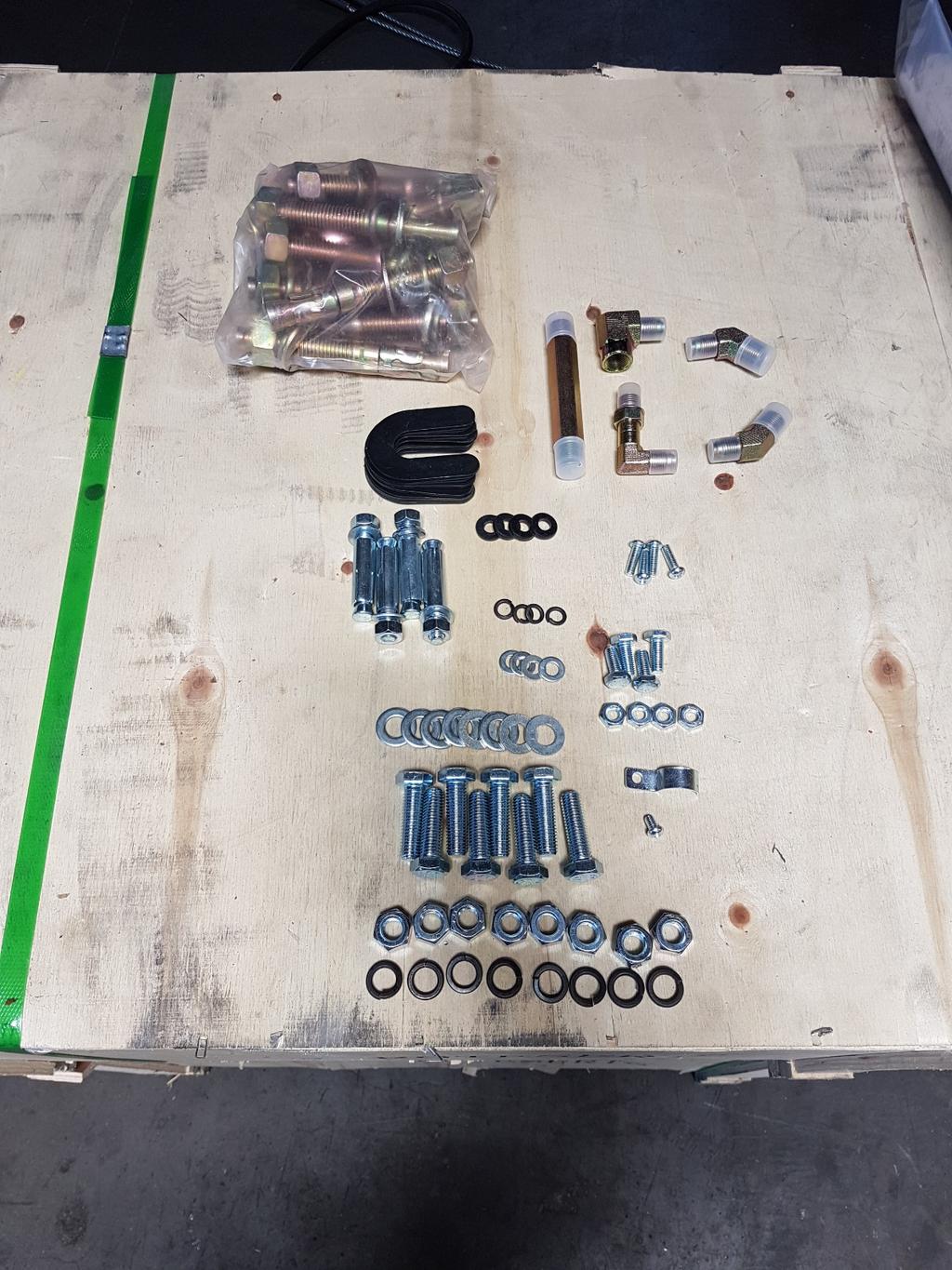
6 FOUNDATION and ANCHORING REQUIREMENTS 1. Concrete shall have compression strength of at least 3,000 PSI and a minimum thickness of 4 in order to achieve a minimum anchor embedment of 3 1/4. NOTE: When using the standard supplied 3/4 x 5 1/2 long anchors; if the top of the anchor exceeds 2 1/4 above the floor grade, you DO NOT have enough embedment. 2. Maintain a 6 minimum distance from any slab edge or seam. Hole to hole spacing should be a minimum 61/2 in any direction. Hole depth should be a minimum of 4. CAUTION!! 3. DO NOT install on asphalt or another similar unstable surface. Columns are supported only by anchoring to floor. 4. Using the horseshoe shims provided, shim each column base as required until each column is plumb. If one column has to be elevated to match the plane of the other column, full size base shim plates should be used. Torque anchors to 85 ft-lbs. Shim thickness MUST NOT exceed ½ when using the 5 1/2 long anchors provided with the lift. Adjust the column extensions plumb. 5. If anchors do not tighten to 120 ft-lbs. installation torque, replace the concrete under each column base with a 4 x 4 x 12 thick 3,000 PSI minimum concrete pad keyed under and flush with the top of existing floor. Allow concrete to cure before installing lifts and anchors (typically 2 to 3 weeks). 6
7 7
8 TOOLS REQUIRED FOR INSTALL The installation of this lift is relatively simple and can be accomplished by two men in a few hours. The following tools and equipment are needed: Hoist or Forklift (optional) Metric Sockets and Open Wrench set Vise grips ISO 32 Light Hydraulic Oil (approx. 12 8mm Socket Head Wrench quarts) Tape Measure Torque wrench with 1-1/8" socket for anchors 4 Level Teflon Tape Rotary Hammer Drill with 3/4 in & ½. Drill Bit Core Drill Rebar Cutter recommended) 8

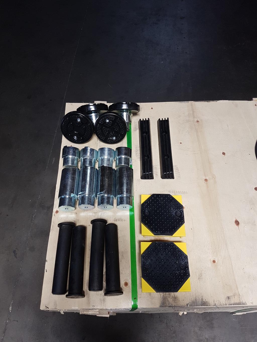
9 INSTALLATION PROCEDURE STEP 1. After unloading the lift, place it near the intended installation location. STEP 2. Remove the shipping bands and packing materials from the unit. The Power Unit will be unpacked from the top. NOTE: Be careful not to drop power unit. STEP 3. Remove the packing brackets and bolts holding the two columns together (do not discard bolts; they are used in the assembly of the lift). STEP 4. Once the power unit column location is decided, insure that the proper lift placement is observed from walls and obstacles. Also check the ceiling height for clearance in this location. NOTE: the power unit column can be located on either side. It is helpful to try and locate the power side with the passenger side of the vehicle when loaded on the lift to save steps during operation. STEP 5. Install the fittings into the hydraulic cylinders, be sure to apply to Teflon tape to the pipe thread end of all the cylinder fittings ONLY. Note: each cylinder has a port on both sides. One has a plastic shipping plug that MUST be removed. See image below 9
10 STEP 6. Install the top plate onto the top of the columns, using the supplied hardware tighten hardware. STEP 7. Using a chalk line make a reference line in your bay for either the front or rear edge of the lift. Step 8. Upright the columns facing each other 134-1/2 from outside base plate to base plate. (check to make sure that the chains are on the chain rollers for each column) Align the edge of the columns on the chalk line making sure to recheck that alignment before anchoring either column. Square the columns by measuring diagonally from corner points on base plates (within 1/4 ). STEP 8. Use the existing holes in column base plate as a guide for drilling the 3/4 diameter holes into the concrete. Drill the anchor holes only for ONE column, installing anchors as you go. You will install anchors in second column after the cables, hoses, and floorplate are installed. NOTE: Drilling thru concrete slab (recommended) will allow the anchor to be driven thru the bottom of slab if the threads are damaged or if the lift will need to be relocated. STEP 9. Using a level, check column for side-to-side plumb and front-to-back plumb. If needed, use horseshoe shims provided by placing shims underneath the base plate and around the anchor bolt. This will prevent bending the column bottom plates (Shim thickness should not exceed ½ ). Tighten ¾ anchor bolts to 150 ft-lbs. of torque. 10

11 STEP 10. Lift the yellow carriage on both columns until the top of the carriage is over the top of the cylinder. Rest the carriage on the automatic safety locks. Use a tape measure to make sure both are sitting at the same height. Step 11. Lay out the equalization cables. Taking one of the threaded cable ends insert it into the front left cable support hole in the carriage from the top until it is reachable from the bottom of the carriage. Install one of the washers followed by both of the cable nuts set the final nut flush with the end of the threads, lock the nuts together tightly. Take the remaining end of the cable & route it up & over the upper pulley. Down through the left rear hole in the carriage. Around the lower left pulley across to the other column up the lower pulley in that column, to the right rear cable support bracket in the carriage. Install one washer & one nut for now. Repeat this process with the second cable. Do not tighten either cable at this time. Step 12. Connect the hydraulic hose between the two columns, do not over tighten the hydraulic fittings. Step 13. Place the drive over plate between the columns, making sure that the plate fits between the two columns. Step 14. Check to make sure the final column is squared up with the reference chalk line & drill anchor & level the final column. Torqueing the anchors to 120ft lbs. 11
12 Step 15. Using the supplied ½ anchors, anchor the drive over plate to the ground & tighten the anchors to 30ft lbs. 12
13 CAUTION!! Only authorized personnel are to operate lift SAFETY AND OPERATING INSTRUCTIONS Read operating and safety procedures manual completely before operating lift. Properly maintain and inspect lift in accordance to owner s manual. Do not operate a lift that is damaged or in need of repair. Allow only authorized personnel in the lift bay. Stay clear of Lift when raising or lowering (NO RIDERS) Keep hands and feet away from pinch points at all times. Never override the Lifts operating and safety controls. If a vehicle is suspected of falling, clear area immediately. Do not rock vehicle while positioned on lift. Always use safety jack stands when removing or installing heavy components. Vehicle Loading Position vehicle for proper weight distribution (center of gravity should be midway between adapters). Swing arms under vehicle to allow adapters to contact at the manufacturer s recommended pick up points. Use caution before lifting pickup trucks, SUV s and other framed vehicles. The individual axle weight capacity should not exceed 1/2 of lift capacity. Make sure vehicle is neither front nor rear heavy. Make sure the lifting pads are in a proper and safe position to support the vehicle. (Ref: Lifting Points Guide and decal on Main side column for typical arm positioning) Raising Lift Push Up switch to raise lift (make sure arm restraints engage or stop and slightly move arm to allow gear to mesh) until tires clear floor. Stop and check for secure contact on adapters and vehicle weight distribution. If secure raise to desired height. ALWAYS lower the lift into the nearest lock position by pressing the lower lever to relieve the hydraulic pressure and let the latch set right in a lock position. Never work under a lift that is not in the locked position. Lowering Lift Clear all obstacles from under lift and vehicle and ensure only the lift operator is in the lift area. Stay clear of lift and raise the lift off the safety locks. Pull safety latch releases and press the lower lever to begin descent. Unload lift by first completely lowering lift, then swinging arms to drive-thru position before moving vehicle. Lift Points Note: Refer to the manufacturer s specific vehicle lifting points. Some vehicles display these points on a label inside the right front door lock face or are identified by triangle shape marks on the vehicle s undercarriage, reference SAE J
14 SAFETY PROCEDURES Never allow unauthorized persons to operate lift. Thoroughly train new employees in the use and care of lift. Caution - the power unit operates at high pressure. Remove passengers before raising vehicle. Prohibit unauthorized persons from being in shop area while lift is in use. Total lift capacity is 9,000 2,250 lbs per lifting pad. Do not exceed maximum weight capacity of lift. Prior to lifting vehicle, walk around the lift and check for any objects that might interfere with the operation of lift and safety latches; tools, air hoses, shop equipment. When approaching the lift with a vehicle, make sure to center the vehicle between the columns so that the tires will clear the swing arms easily. Slowly drive the vehicle between the columns. It is recommended to have someone outside the vehicle guide the driver. Always lift vehicle using all four pads. Never use lift to raise one end or side of vehicle. Always raise vehicle about 3 and check stability by rocking vehicle. Prior to lowering vehicle, walk around the lift and check for any objects that might interfere with the operation of lift and safety latches; tools, air hoses, shop equipment. Always lower lift to the lock position before going under vehicle. Never allow anyone to go under the lift when raising or lowering. 14
15 PREVENTIVE MAINTENANCE SCHEDULE The periodic Preventive Maintenance Schedule given is the suggested minimum requirements and minimum intervals; accumulated hours or monthly period, whichever comes sooner. Periodic maintenance is to be performed on a daily, weekly, and yearly basis as given in the following paragraphs. WARNING!! Occupational Safety and Health Administration (OSHA) and the American National Standards Institute (ANSI) requires users to inspect lifting equipment at the start of every shift. These and other periodic inspections are the responsibility of the user. Failure to perform the daily pre-operational check can result in expensive property damage, lost production time, serious personal injury, and even death. The safety latch system must be checked and working properly before the lift is put to use. Failure to heed this warning can result in death or serious injury, or damage to equipment. If you hear a noise not associated with normal lift operation, or, if there are any indications of impending lift failure - CEASE OPERATION IMMEDIATELY! - Inspect, correct and/or replace parts as required. Daily Pre-Operation Check (8-Hours) 1. Check safety lock audibly and visually while in operation 2. Check safety latches for free movement and full engagement with rack. 3. Check hydraulic connections, and hoses for leakage. 4. Check chain connections - bends, cracks-and loose links. 5. Check cable connections- bends, cracks-and looseness. 6. Check for frayed cables in both raised and lowered position. 7. Check snap rings at all rollers and sheaves. 8. Check bolts, nuts, and screws and tighten if needed. 9. Check wiring & switches for damage. 10. Keep base plate free of dirt, grease or any other corrosive substances. 11. Check floor for stress cracks near anchor bolts. 12. Check swing arm restraints. Weekly Maintenance (every 40-Hours) 1. Check anchor bolts torque to 120 ft-lbs for the ¾ in. anchor bolts. Do not use an impact 1. wrench to tighten anchor bolts. 2. Check floor for stress cracks near anchor bolts. 3. Check hydraulic oil level. 4. Check and tighten bolts, nuts, and screws. 5. Check cylinder pulley assembly for free movement or excessive wear on cylinder yoke or pulley pin. 6. Check cable pulley for free movement and excessive wear. Yearly Maintenance 1. Lubricate chains 2. Grease rub blocks and column surface contacting rub blocks 1. Change the hydraulic fluid - good maintenance procedure makes it mandatory to keep hydraulic fluid clean. No hard-fast rules can be established; - operating temperature, type of service, contamination levels, filtration, and chemical composition of fluid should be considered. If operating in dusty environment shorter interval may be required. Special Maintenance Tasks NOTE: The following items should only be performed by a trained maintenance expert: Replacement of hydraulic hoses. Replacement of chains and rollers. Replacement of cables and sheaves. Replacement or rebuilding air and hydraulic cylinders as required. Replacement or rebuilding pumps / motors as required. Checking of hydraulic cylinder rod and rod end (threads) for deformation or damage. 15
16 16
17 17
18 18
19 19
20 Troubleshooting Information The common problems that may be encountered and their probable causes are covered in the following paragraphs: PROBLEM SOLUTION Motor Does Not Operate Failure of the motor to operate is normally caused by one of the following: 1. Breaker or fuse blown. 2. Faulty wiring connections; call electrician. 3. Defective up button; call electrician for service. Motor Functions but Lift Will If the motor is functioning, but the lift will not rise do the following in the order Not Rise given: 1. A piece of trash is under check valve. Push handle down and push the up button at the same time. Hold for seconds. This should flush the system. 2. Check the clearance between the plunger valve of the lowering handle. There should be 1/16 clearance. 3. Remove the check valve cover and clean ball and seat. WARNING!! Failure to properly relieve pressure in the following step can cause injury to personnel. This lift uses ISO Grade 32 or other good grade non-detergent hydraulic oil at a high hydraulic pressure. Be familiar with its toxicological properties, precautionary measures to take, and first aid measures as stated in the Safety Summary before performing any maintenance with the hydraulic system. Oil Blows out Breather of Power Unit Motor Hums and Will Not Run Lift Jerks Going Up and Down Oil Leaks Lift makes excessive noise / vibrates 4. Oil level too low. Oil level should be just under the vent cap port when the lift is down. Relieve all hydraulic pressure and add oil as required. If oil blows out of the breather of the power unit, take the following actions: 1. Oil reservoir overfilled. Relieve all pressure and siphon out hydraulic fluid until at a proper level 2. Lift lowered too quickly while under a heavy load. Lower the lift slowly under heavy loads. If the motor hums but fails to run, take the following actions: 1. Lift overloaded. Remove excessive weight from lift WARNING!! The voltages used in the lift can cause death or injury to personnel. In the following steps, make sure that a qualified electrician is used to perform maintenance 2. Faulty wiring Call electrician 3. Bad capacitor Call electrician 4. Low voltage Call electrician 1. If the lift jerks while going up and down, it is usually a sign of air in the hydraulic system. Raise lift all the way to top and return to floor. Repeat 4-6 times. Do not let this overheat power unit. Oil leak causes at the power unit and cylinders are normally caused by the following: 1. Power unit: if the power unit leaks hydraulic oil around the tank-mounting flange check the oil level in the tank. The level should be two inches below the flange of the tank. A screwdriver can be used as a dipstick. 2. Cylinder - Piston Rod: the rod seal of the cylinder is out. Rebuild or replace the cylinder. 3. Cylinder - Vent: the piston seal of the cylinder is out. Rebuild or replace the cylinder. Excessive noise from the lift is normally caused by the following: 1. Cross beam ends are rubbing the columns. Readjustment needed. 2. Cylinder too tight, load lift half capacity and cycle up and down a few times to break in. Lift cylinder should quiet down with use. If not contact your Direct Lift Distributor to purchase an Oil Additive. 3. May have excessive wear on cable sheaves or shafts. Replace them. 20
21 ILLUSTRATED PARTS BREAKDOWN 21
22 22
23 23

24 PARTS LIST OF BP LIFT 24
25 PARTS LIST OF BP LIFT 25
Floor Plate Style Lift And Overhead Beam Style Lift. Two Post Lift
 Floor Plate Style Lift And Overhead Beam Style Lift 9,000 POUND Two Post Lift ASSEMBLY & OPERATION INSTRUCTION TABLE OF CONTENTS Important Note Page 3 Definition Page 4 Preparation and General Information
9,000 POUND TWO-COLUMN AUTOMOTIVE LIFT. Model: NW-2-9KACD MANUAL
 9,000 POUND TWO-COLUMN AUTOMOTIVE LIFT Model: NW-2-9KACD MANUAL 1 9,000 POUND CAPACITY MODEL: NW-2-9KACD TWO-COLUMN AUTOMOTIVE LIFT READ THIS ENTIRE MANUAL BEFORE OPERATION BEGINS RECORD BELOW THE FOLLOWING
IMPORTANT INFORMATION
 TABLE OF CONTENTS IMPORTANT INFORMATION... 2 LIFT AREA LAYOUT INFORMATION... 3 TOOLS and EQUIPMENT REQUIRED FOR INSTALL... 4 INSTALLATION PROCEDURE... 5 FOUNDATION and ANCHORING REQUIREMENTS... 6 DEFINITION
Read this entire manual before operation begins.
 Read this entire manual before operation begins. Record below the following information which is located on the serial number data plate. Serial No. Model No. Date of Installation Contents Important Information........
INSTALLATION MANUAL & OPERATION INSTRUCTIONS. OVERHEAD CAR LIFT 2-POST LIFT AUTO HOIST APlusLift HW-10KOH
 INSTALLATION MANUAL & OPERATION INSTRUCTIONS OVERHEAD CAR LIFT 2-POST LIFT AUTO HOIST APlusLift HW-10KOH 1 READ THIS MANUAL COMPLETELY BEFORE INSTALLING LIFT!!! DISTRIBUTED BY: Songa Enterprises LLC 8512
Model: TPO310-ACX MANUAL
 PEAK-AUTOLIFT 10,000 POUND TWO-COLUMN AUTOMOTIVE LIFT Model: TPO310-ACX MANUAL AutoTool 2739 W 79 th St #16 Hialeah, FL 33016 Phone: (305) 825-9600 www.autotool.net Rev. 2010 Table of Contents WARRANTY...3
Model FP12K-K Flat Deck Four-Post Lift
 Model FP12K-K Flat Deck Four-Post Lift (12,000LBS Capacity) ASSEMBLY & OPERATION INSTRUCTION 2006.4. TABLE OF CONTENTS Important Note--------------------------------------------------------------------------------Page
TP15KC-KX Two-Post Clear Floor Lift
 TP15KC-KX Two-Post Clear Floor Lift (Symmetric) 15,000 lbs. Capacity (3,750 lbs. Max per Arm) ASSEMBLY & OPERATION INSTRUCTION MANUAL Feb. 2017 IMPORTANT NOTES READ THE INSTALLATION AND OPERATION MANUAL
ATD-2P9A 9,000 lbs. Two Post Clear Floor Lift Owner s Manual
 ATD-2P9A 9,000 lbs. Two Post Clear Floor Lift Owner s Manual Features: Specifications: IMPORTANT NOTES READ THE INSTALLATION AND OPERATION MANUAL IN ITS ENTIRETY BEFORE ATTEMPTING TO INSTALL THE LIFT.
INSTALLATION & OPERATION MANUAL
 Two-Post Clear Floor Lift (Asymmetric) 9,000 lbs. Capacity (2,250 lbs. Max per Arm) INSTALLATION & OPERATION MANUAL IMPORTANT NOTES READ THE INSTALLATION AND OPERATION MANUAL IN ITS ENTIRETY BEFORE ATTEMPTING
INSTALLATION / OWNERS MANUALS
 Floor Plate Automotive Lift 9,000 POUND CAPACITY IMPORTANT Reference ANSI/ALI ALIS, Safety Requirements for Installation and Service of Automotive Lifts before installing lift. INSTALLATION / OWNERS MANUALS
ATD2P11BS. Two-Post Clear Floor Bi-Symmetric Automotive Lift. Installation & Operation Manual. 11,000 lbs. Capacity. (2,750 lbs.
 Two-Post Clear Floor Bi-Symmetric Automotive Lift 11,000 lbs. Capacity (2,750 lbs. Max per Arm) Installation & Operation Manual 1. Safety Information 1.1 Note, Caution and Warning 1.2 Important Information
Model FP14KO-A Wheel alignment & Open Front Four-Post Lift
 Model FP14KO-A Wheel alignment & Open Front Four-Post Lift ( 14000LBS / 6300Kg Capacity) ASSEMBLY & OPERATION INSTRUCTIONS ( Series T1) 2009.7. INTRODUCTION Model FP14KO-A is a four-post lift is used in
Model FP14KA-C Alignment Four-Post Lift
 Model FP14KA-C Alignment Four-Post Lift (14000 LBS Capacity) ASSEMBLY & OPERATION INSTRUCTION 2006.4. TABLE OF CONTENTS Important Note--------------------------------------------------------------------------------Page
ATD-4P9DXL. Four Post Lift. 9,000 lbs. Capacity. (4,500 lbs. per axle) INSTALLATION / OWNERS MANUAL
 INSTALLATION / OWNERS MANUAL") ATD-4P9DXL Four Post Lift 9,000 lbs. Capacity (4,500 lbs. per axle) INSTALLATION / OWNERS MANUAL Jan 2017 READ THIS MANUAL THOROUGHLY BEFORE INSTALLING, OPERATING, OR MAINTAINING THIS LIFT. WHEN DONE WITH
ATD-4P9DXL Four Post Lift 9,000 lbs. Capacity (4,500 lbs. per axle) INSTALLATION / OWNERS MANUAL Jan 2017 READ THIS MANUAL THOROUGHLY BEFORE INSTALLING, OPERATING, OR MAINTAINING THIS LIFT. WHEN DONE WITH
TL4.0OHDI (9KOH) INSTALLATION / OWNERS MANUAL
 INSTALLATION / OWNERS MANUAL") TL4.0OHDI (9KOH) INSTALLATION / OWNERS MANUAL TWO POST HOIST Capacity: 4 TONNE Read this manual thoroughly before installing, operating, or maintaining this lift. When done with installation be sure to
TL4.0OHDI (9KOH) INSTALLATION / OWNERS MANUAL TWO POST HOIST Capacity: 4 TONNE Read this manual thoroughly before installing, operating, or maintaining this lift. When done with installation be sure to
Read this entire manual before operation begins.
 Read this entire manual before operation begins. Record below the following information which is located on the serial number data plate. Serial No. Model No. Date of Installation Contents Important Information........
BLAZER 9000 LUBE LIFT OPERATOR AND PARTS MANUAL
 BLAZER 9000 LUBE LIFT OPERATOR AND PARTS MANUAL Blazer 9000 Lube Lift Operator s Manual Note: Instructions must be read thoroughly before installing, operating, or maintaining the lift. Devon Lube Center
Read this entire manual before operation begins.
 Read this entire manual before operation begins. Record below the following information which is located on the serial number data plate. Serial No. Model No. Date of Installation Contents Important Information........
ATD-4P14CCA 14,000 lb Capacity Closed Front Alignment Lift ASSEMBLY & OPERATION INSTRUCTION MANUAL
 ATD-4P14CCA 14,000 lb Capacity Closed Front Alignment Lift ASSEMBLY & OPERATION INSTRUCTION MANUAL 14,000 LB. FOUR POST CABLE DRIVEN ALIGNMENT LIFT ATD-4P14CCA 14,000 lb. capacity Four post Cable driven
ATTENTION. 1. Do not attempt to use the power unit to extend your cylinder. This must be done manually.
 NSS8XLT Installation Manual ATTENTION By following the instructions in this manual you can save yourself much time, frustration and money. The installation of your lift will take 4-5 hours. Do not rush.
TWO POST LIFT INSTALLATION AND OWNERS MANUAL
 TWO POST LIFT INSTALLATION AND OWNERS MANUAL DP15, DP15-2 Capacity 15,000 lbs. 1. TABLE OF CONTENTS 2. Important Information.. 2 3. Section 1 Owner s Manual Safety Instructions... 3 Monthly Maintenance...
FOUR-POST LIFT. 14,000 lbs. Capacity
 FOUR-POST LIFT 14,000 lbs. Capacity Note: At the rated capacity of 14,000 lbs. lift was designed for: 101" Minimum wheelbase for models without rolling jacks 124" Minimum wheelbase for models with rolling
FP8K-B, FP8K-DX & FP8K-DX-XLT Four Post Storage Lifts
 FP8K-B, FP8K-DX & FP8K-DX-XLT Four Post Storage Lifts 8,000 lbs. Capacity (4,000 lbs. per axle) INSTALLATION / OWNERS MANUAL READ THIS MANUAL THOROUGHLY BEFORE INSTALLING, OPERATING, OR MAINTAINING THIS
Lifting height 5.5" - 72" with adapters " Height overall 165" Width between columns 122" Drive through 109" Width overall 151.
 Model Number TP12KC-D Capacity 12,000 lbs. Lifting height 5.5" - 72" with adapters 79.625" Height overall 165" Width between columns 122" Drive through 109" Width overall 151.125" Arm extension 37.5" -
Read this entire manual before operation begins.
 Read this entire manual before operation begins. Record below the following information which is located on the serial number data plate. Serial No. Model No. Date of Installation Contents Specifications.............
Installation Instructions Capacity 10,000 lbs. (100 Series Lift)
") Installation Instructions Capacity 10,000 lbs. (100 Series Lift) IMPORTANT Reference ANSI/ALI ALIS, Safety Requirements for Installation and Service of Automotive Lifts before installing lift. OPERATING
Installation Instructions Capacity 10,000 lbs. (100 Series Lift) IMPORTANT Reference ANSI/ALI ALIS, Safety Requirements for Installation and Service of Automotive Lifts before installing lift. OPERATING
CONTENTS. Product Features and Specifications Installation Requirement Installation Exploded View Operation Instruction...
 1 CONTENTS Product Features and Specifications... 3 Installation Requirement... 5 Installation... 6 Exploded View... 20 Test... 22 Operation Instruction... 25 Maintenance... 26 Trouble Shooting... 27 Parts
FP8K-B, FP8K-DX & FP8K-DX-XLT Four Post Storage Lifts
 FP8K-B, FP8K-DX & FP8K-DX-XLT Four Post Storage Lifts 8,000 lbs. Capacity (4,000 lbs. per axle) INSTALLATION / OWNERS MANUAL READ THIS MANUAL THOROUGHLY BEFORE INSTALLING, OPERATING, OR MAINTAINING THIS
Read this entire manual before operation begins.
 Read this entire manual before operation begins. Record below the following information which is located on the serial number data plate. Serial No. Model No. Date of Installation Contents Specifications.............
Make sure you have extra help or heavy duty lifting equipment when unloading and assembling the Atlas Auto SPINS Rotisserie.
 IMPORTANT INFORMATION Any freight damage must be noted on the freight bill before signing. Identify the components and check for shortages. If shortages are discovered, please contact Greg Smith Equipment
Read this entire manual before operation begins.
 Read this entire manual before operation begins. Record below the following information which is located on the serial number data plate. Serial No. Model No. Date of Installation Contents Important Information........
Read this entire manual before operation begins.
 Read this entire manual before operation begins. Record below the following information which is located on the serial number data plate. Serial No. Model No. Date of Installation Contents Specifications.............
TWO POST LIFT INSTALLATION AND OWNERS MANUAL. January 2008 rev. E I MAN
 TWO POST LIFT INSTALLATION AND OWNERS MANUAL DP15, DP15-2 Capacity 15,000 lbs. January 2008 rev. E 1. TABLE OF CONTENTS 2. Important Information.. 2 3. Section 1 Owner s Manual Safety Instructions... 3
Atlas PV-9WP Addendum
 Atlas PV-9WP Addendum 9,000 lb. Capacity Two-Post Overhead Lift The Atlas PV-9WP above ground hoist is 6 inches wider than the Atlas PV-9P, giving it an overall width of 141 (11 9 ) and a drive thru width
SCISSOR LIFT Model MR6K-38 /161108A 6,000lb Capacity Operation Manual
 SCISSOR LIFT Model MR6K-38 /161108A 6,000lb Capacity Operation Manual (Version A) 2009. Apr. CONTENT 1. Safety Note, Caution and Warning Important Information Safety Instructions 2. Technical Manual Product
CONTENTS. Product Features and Specifications...1. Installation Requirement Steps of Installation.. 5. Exploded View Test Run...
 CONTENTS Product Features and Specifications...1 Installation Requirement... 3 Steps of Installation.. 5 Exploded View...18 Test Run...21 Operation Instruction...22 Maintenance... 23 Trouble Shooting...
CONTENTS. Product Features and Specifications Installation Requirement Steps of Installation 4. Exploded View Test Run...
 CONTENTS Product Features and Specifications... 1 Installation Requirement... 3 Steps of Installation 4 Exploded View... 14 Test Run... 16 Operation Instruction... 19 Maintenance... 20 Trouble Shooting...
TP10KACD REV A
 TP10KACD 10, 000l bcapaci t y TwoPostAsymmet r i caut oli f t REV A-061813 Table of contents Important Information Section 1 Owner s Manual Safety Instructions Monthly Maintenance Troubleshooting Section
IMPORTANT INFORMATION
 1 TABLE OF CONTENTS IMPORTANT INFORMATION... pg 2 LIFT SPECIFICATIONS & FLOOR PLAN... pg 3 TOOLS REQUIRED... pg 4 INSTALLATION INSTRUCTIONS... pg 4 CASTER KIT ASSEMBLY / INSTALLATION... pg 6 FOUNDATION
PP8S Four Post Lift 8,000 lbs. Capacity
 PP8S Four Post Lift 8,000 lbs. Capacity (4,000 lbs. per axle) Minimum wheelbase 100" at rated capacity IMPORTANT INSTALLATION / OWNERS MANUAL Read this manual thoroughly before installing, operating, or
Installation Instructions Capacity 10,000 lbs. DP10 (200 Series Lift)
") Installation Instructions Capacity 10,000 lbs. DP10 (200 Series Lift) IMPORTANT Reference ANSI/ALI ALIS, Safety Requirements for Installation and Service of Automotive Lifts before installing lift. OPERATING
Installation Instructions Capacity 10,000 lbs. DP10 (200 Series Lift) IMPORTANT Reference ANSI/ALI ALIS, Safety Requirements for Installation and Service of Automotive Lifts before installing lift. OPERATING
Read this entire manual before operation begins.
 Read this entire manual before operation begins. Record below the following information which is located on the serial number data plate. Serial No. Model No. Date of Installation Contents Specifications.............
Models PR-12F PR-12C PR-15C SURFACE MOUNTED TWO-POST LIFTS INSTALLATION AND OPERATION MANUAL
 Forward this manual to all operators. Failure to operate this equipment as directed may cause injury. INSTALLATION AND OPERATION MANUAL SURFACE MOUNTED TWO-POST LIFTS Models PR-12F PR-12C PR-15C Keep this
2-Post Lift Operations and Maintenance Manual
 2-Post Lift Operations and Maintenance Manual Table Of Contents Safety Instructions... 2 Owner/Employer Responsibilities / Operating Conditions... 3 Operating Instructions... 4 Maintenance Instructions...
TP12KC-DX. Two Post Clear Floor. Automotive Lift. 12,000 lb. Capacity. (3,000 lbs. Max Capacity per Arm) Installation & Operation Manual
 Installation & Operation Manual") Two Post Clear Floor Automotive Lift 12,000 lb. Capacity (3,000 lbs. Max Capacity per Arm) Installation & Operation Manual IMPORTANT!! READ MANUAL THOROUGHLY BEFORE INSTALLING, OPERATING, SERVICING OR
Two Post Clear Floor Automotive Lift 12,000 lb. Capacity (3,000 lbs. Max Capacity per Arm) Installation & Operation Manual IMPORTANT!! READ MANUAL THOROUGHLY BEFORE INSTALLING, OPERATING, SERVICING OR
Installation and Operation Manual
 1645 Lemonwood Dr. Santa Paula, CA 93060 USA Toll Free: 1 (800) 253-2363 Tel: 1 (805) 933-9970 rangerproducts.com Ranger Floor Jack Installation and Operation Manual Manual Revision B July 2017 Manual
Installation Manual. Installation Instructions. Operation. TP15KC Parts Check List Notes about your TP15KC lift
 Installation Manual Parts Check List Notes about your lift Installation Instructions Step 1 Measure lift area and check for defects Step 2 Cylinder assembly Step 3 Position columns and uprights, level
Installation, operation and maintenance manual
 Installation, operation and maintenance manual HCT1LX30 FULL RISE SCISSOR LIFT READ THIS ENTIRE MANUAL BEFORE INSTALLATION TO ENSURE CORRECT OPERATION AND A LONG SERVICE LIFE 2 Tiraines str. Riga, LV 1058
Installation Instructions X-Force UTV Lift (000 Series) Capacity 2,275 lbs (1,035 kg)
 Capacity 2,275 lbs (1,035 kg)") Installation Instructions X-Force UTV Lift (000 Series) Capacity 2,275 lbs (1,035 kg) Read entire manual before assembling, installing, operating, or servicing this equipment. LP20640 IN20793 September
Installation Instructions X-Force UTV Lift (000 Series) Capacity 2,275 lbs (1,035 kg) Read entire manual before assembling, installing, operating, or servicing this equipment. LP20640 IN20793 September
It is the shop owner's responsibility to train all operators in lift operation and safety.
 2 Your new lift will provide years of dependable service if installed, operated and maintained properly. Read and be prepared to follow all safety, installation, operation, and maintenance instructions
GLO-8000 SERIES (GLO-8000 & GLO-8000XLT)
") GLO-8000 SERIES (GLO-8000 & GLO-8000XLT) 8,000 LBS. CAPACITY FOUR-POST STORAGE LIFT INSTALLATION & OPERATION MANUAL SERIAL NUMBER: INSTALLATION DATE: EAGLE EQUIPMENT 1-800-336-2776 REV2011 03.0 BD SHIPPING
GLO-8000 SERIES (GLO-8000 & GLO-8000XLT) 8,000 LBS. CAPACITY FOUR-POST STORAGE LIFT INSTALLATION & OPERATION MANUAL SERIAL NUMBER: INSTALLATION DATE: EAGLE EQUIPMENT 1-800-336-2776 REV2011 03.0 BD SHIPPING
READ THIS MANUAL BEFORE INSTALLATION AND/OR OPERATION! WARNING:
 1 READ THIS MANUAL BEFORE INSTALLATION AND/OR OPERATION! This is a vehicle lift operation manual and no attempt is made or implied herein to instruct the user in lifting methods particular to an individual
INSTALLATION, OPERATION & MAINTENANCE MANUAL
 INSTALLATION, OPERATION & MAINTENANCE MANUAL Two Post Surface Mounted Lift MODEL X10 10,000 LBS. CAPACITY 2500 LBS. PER ARM 200 Cabel Street, P.O. Box 3944 Louisville, Kentucky 40201-3944 Email:sales@challengerlifts.com
MR6K lb Capacity Portable Mid-Rise Scissor Lift. Operation Manual
 MR6K-38 6000 lb Capacity Portable Mid-Rise Scissor Lift Operation Manual 6,000 LB. PORTABLE MID-RISE FRAME LIFT A comfortable 38 working height, twin cylinders and double safety locks make this portable
SPO15, SPO18 I N S T A L L A T I O N I N S T R U C T I O N S
 SPO15, SPO18 Sprinter SPO15 (3A0 Lifts) Capacity 11,000 lbs. Standard SPO15 (300 Series Lifts) Capacity 15,000 lbs. Standard SPO18 (300 Series Lifts) Capacity 18,000 lbs. SPO15 (31A0 Lifts) Capacity 14,300
TWO POST LIFT INSTALLATION AND OWNERS MANUAL Capacity 10,000 lbs.
 TWO POST LIFT INSTALLATION AND OWNERS MANUAL Capacity 10,000 lbs. May 2009 All rights reserved. CO7378.2 IN60005 Rev. - 5/7/2009 TABLE OF CONTENTS Important Information...2 Section 1 Owner s Manual Safety
Read this entire manual before operation begins.
 Rev. 12/12/2017 Read this entire manual before operation begins. Record below the following information which is located on the serial number data plate. Serial No. Model No. Date of Installation Contents
T R I N S I N S U C N S
 R O TA R Y V A L I D A T E D CERTIFIED B Y E L T SPOA7, SPOA9, SPO9 Two Post Surface Mounted Lift (200 Series Lifts) SPOA7 Capacity 7,000lbs. SPOA9 Capacity 9,000lbs. 1750 lbs. per arm 2250 lbs. per arm
PP8 Plus Long Four Post Lift 8,000 lbs. Capacity
 PP8 Plus Long Four Post Lift 8,000 lbs. Capacity (4,000 lbs. per axle) Minimum wheelbase 115 at rated capacity IMPORTANT Reference ANSI/ALI ALIS, Safety Requirements for Installation and Service of Automotive
1300 lb Capacity Trike Lift
 M-1300C-TRIKE 1300 lb Capacity Trike Lift USER S MANUAL TRIKE MOTORCYCLE LIFT An extra wide platform designed especially for three-wheel motorcycles. M-1300-TRIKE Trike Motorcycle Lift SPECIFICATIONS:
Model PL-7 / PL-7X AUTOMOBILE STACKER INSTALLATION AND OPERATION MANUAL
 Forward this manual to all operators. Failure to operate this equipment as directed may cause injury. AUTOMOBILE STACKER INSTALLATION AND OPERATION MANUAL Model PL-7 / PL-7X Keep this operation manual
CONTENTS. Product Features and Specifications...1. Installation Requirement Steps of Installation.. 5. Exploded View Test Run...
 CONTENTS Product Features and Specifications...1 Installation Requirement... 4 Steps of Installation.. 5 Exploded View...21 Test Run...26 Operation Instruction...27 Maintenance... 28 Trouble Shooting...
CONTENTS. Product Features and Specifications...1. Installation Requirement...3. Steps of Installation...4. Exploded View Test Run...
 TP10AS 2-POST LIFT CONTENTS Product Features and Specifications...1 Installation Requirement...3 Steps of Installation...4 Exploded View...24 Test Run....28 Operation Instruction...29 Maintenance...30
& Operation Instructions
 Installation Manual & Operation Instructions 4 Post Lift* PSE 10,000 CSP XLT INSTALLATION Manual PSE 10,000 CSP XLT (Portable 4 Post Lift) Heavy-Duty 4 Post Lift 10,000 LB. Capacity Lift Features: 4 Oil
Parallel Lift Rack MODEL RM
 Form 4401T, 09-03 Supersedes Form 4401T, 10-00 OPERATION INSTRUCTIONS Parallel Lift Rack MODEL RM Copyright 1998-2003 Hunter Engineering Company Contents 1. For Your Safety... 1 1.1 Warning/Instruction
MSC-6KLP Low Profile Mobile Single Column Lift. 6,000 lb. Capacity (1,500 lbs. Max Capacity per Arm) Installation & Operation Manual
 Installation & Operation Manual") Low Profile Mobile Single Column Lift 6,000 lb. Capacity (1,500 lbs. Max Capacity per Arm) Installation & Operation Manual INDEX PREFACE-------------------------------------------------------------------------------
Low Profile Mobile Single Column Lift 6,000 lb. Capacity (1,500 lbs. Max Capacity per Arm) Installation & Operation Manual INDEX PREFACE-------------------------------------------------------------------------------
QJY245DS~DA. Two Post Lift Installation & Adjustment Manual
 QJY245DS~DA Two Post Lift Installation & Adjustment Manual Table of Contents 1. Warning 2 2. Summary 2 3. Use 2 4. Mainly technology parameter 2 5. Basic structure of the production 3 6. Safety device
Read this entire manual before operation begins.
 Read this entire manual before operation begins. Record below the following information which is located on the serial number data plate. Serial No. Model No. Date of Installation Contents Specifications.............
TWO POST LIFT INSTALLATION AND OWNERS MANUAL Capacity 10,000 lbs.
 TWO POST LIFT INSTALLATION AND OWNERS MANUAL Capacity 10,000 lbs. October 2012 by Vehicle Service Group All rights reserved. CO8347 IN60009 Rev. H 10/18/2012 TABLE OF CONTENTS Important Information...2
INSTRUCTION MANUAL 16K - Fifth Wheel Hitch
 You can take it with you. INSTRUCTION MANUAL 16K - Fifth Wheel Hitch Product No. 30047 DEALER/INSTALLER: END USER: (1) Provide this Manual to end user. (2) Physically demonstrate hitching and unhitching
Index. 1. Important safety instructions Overview of the lift Installation instructions Operation instructions 8-9
 2 Index 1. Important safety instructions 4-5 1.1 Safety Warnings 1.2 Qualified personnel 1.3 Safety 1.4 Warning signs 2. Overview of the lift 6 2.1 General descriptions 2.2 Technical data 2.3 Construction
Two Post Surface Mounted Lift 12,000 LBS. CAPACITY 3000 LBS. PER ARM
 INSTALLATION, OPERATION & MAINTENANCE MANUAL Two Post Surface Mounted Lift MODEL EELR537A 12,000 LBS. CAPACITY 3000 LBS. PER ARM Snap-On Equipment 309 Exchange Avenue, Conway, Arkansas, 72032 Tel: 501-450-1500
SPOA10NB, SPOA10, SPO10 ( Series Lifts) SPOA7, SPOA9, SPO9 (500 Series Lifts)
 SPOA7, SPOA9, SPO9 (500 Series Lifts)") O PE SPOA10NB, SPOA10, SPO10 (200-700 Series Lifts) SPOA7, SPOA9, SPO9 (500 Series Lifts) SPOA7 Capacity 7,000 lbs. SPOA9, SPO9 Capacity 9,000 lbs. SPOA10NB, SPOA10, SPO10 Capacity 10,000 lbs. R A TI O
O PE SPOA10NB, SPOA10, SPO10 (200-700 Series Lifts) SPOA7, SPOA9, SPO9 (500 Series Lifts) SPOA7 Capacity 7,000 lbs. SPOA9, SPO9 Capacity 9,000 lbs. SPOA10NB, SPOA10, SPO10 Capacity 10,000 lbs. R A TI O
ASSEMBLY & OPERATION INSTRUCTION MANUAL
 LR-26-PAD 6000 lb Capacity Low-Rise Pad Lift ASSEMBLY & OPERATION INSTRUCTION MANUAL 6,000 LB. LOW-RISE PAD LIFT Easy frame lifting on padded runways. Great for wheel and brake work, tire and wheel changing
SPECIFICATIONS CONTENTS: Specifications Warning Information. Operating Instructions Preventative Maintenance and Troubleshooting
 Model 3322 22 Ton Air/Hydraulic Truck Axle Jack OWNER'S MANUAL CONTENTS: Page 1 Page 2 Page 3-4 Page 4-5 Page 5 Page 6 Page 7 Page 8 Specifications Warning Information Assembly Operating Instructions Preventative
Challenger Lifts, Inc. MODEL 12000
 Challenger Lifts, Inc. MODEL 12000 TWO POST SURFACE MOUNTED LIFT OPERATION, INSTALLATION & MAINTENANCE MANUAL IMPORTANT READ THIS MANUAL COMPLETELY BEFORE INSTALLING OR OPERATING THE LIFT 200 CABEL STREET,
GLO-7000 SERIES (GLO-7000 & GLO-7000XLT)
") GLO-7000 SERIES (GLO-7000 & GLO-7000XLT) 7,000 LBS. CAPACITY FOUR-POST STORAGE LIFT (BLUE) INSTALLATION & OPERATION MANUAL SERIAL NUMBER: INSTALLATION DATE: EAGLE EQUIPMENT 1-800-336-2776 (STANDARD) SHIPPING
GLO-7000 SERIES (GLO-7000 & GLO-7000XLT) 7,000 LBS. CAPACITY FOUR-POST STORAGE LIFT (BLUE) INSTALLATION & OPERATION MANUAL SERIAL NUMBER: INSTALLATION DATE: EAGLE EQUIPMENT 1-800-336-2776 (STANDARD) SHIPPING
ATO7 (100 Series Lifts)
") O PE ATO7 (100 Series Lifts) Capacity 7000 lbs. (3181 kg) 1750 lbs. (795.25 kg) per arm R A TI O N & M AI N TE N A N N CE Table Of Contents Safety Instructions... 2 Owner/Employer Responsibilities / Operating
O PE ATO7 (100 Series Lifts) Capacity 7000 lbs. (3181 kg) 1750 lbs. (795.25 kg) per arm R A TI O N & M AI N TE N A N N CE Table Of Contents Safety Instructions... 2 Owner/Employer Responsibilities / Operating
MR6K-48X. Mid-Rise Scissor Lift ASSEMBLY & OPERATION INSTRUCTION MANUAL. 6,000 lbs.
 MR6K-48X Mid-Rise Scissor Lift 6,000 lbs. ASSEMBLY & OPERATION INSTRUCTION MANUAL November 2014 Important! Be sure to read the operating instructions before operating your lift! Getting Ready Make sure
STACKER INSTRUCTION MANUAL
 STACKER INSTRUCTION MANUAL The Mobile Stackers are lifting devices featuring easy, flexible, reliable and safe operation suitable for transportation of loads in such applications as warehouses, manufacturing
Models: SURFACE MOUNTED FOUR-POST LIFTS INSTALLATION AND OPERATION MANUAL
 Forward this manual to all operators. Failure to operate this equipment as directed may cause injury. INSTALLATION AND OPERATION MANUAL SURFACE MOUNTED FOUR-POST LIFTS Models: FL-18 BP-18 BP-27/ BP-27A
SPECIFICATIONS CONTENTS: Warning Information. Operating Instructions Preventative Maintenance and Troubleshooting
 Model 3322 22 Ton Air/Hydraulic Truck Axle Jack OWNER'S MANUAL CONTENTS: Page 1 Page 2 Page 3-4 Page 4-5 Page 5 Page 6 Page 7 Page 8 Specifications Warning Information Assembly Operating Instructions Preventative
ASSEMBLY & OPERATION INSTRUCTION MANUAL
 Sliding Bridge Jack 3,500 lbs. Capacity ASSEMBLY & OPERATION INSTRUCTION MANUAL TABLE OF CONTENTS Specifications... 2 Description & Features... 3 Installation Instructions... 4 Safety Instructions... 4
SL210i/SL212i/SL19i. Table Of Contents
 SL210i/SL212i/SL19i (700 Series) SL19i Capacity 9,000 lbs. SL210i Fixed Pad Capacity 9,000 lbs. SL210i Capacity 10,000 lbs. SL212i Capacity 12,000 lbs. Table Of Contents Owner/Employer Responsibilities...
Challenger Lifts, Inc. MODELS & 18000
 Challenger Lifts, Inc. MODELS 15000 & 18000 TWO POST SURFACE MOUNTED LIFT OPERATION, INSTALLATION & MAINTENANCE MANUAL IMPORTANT READ THIS MANUAL COMPLETELY BEFORE INSTALLING OR OPERATING THE LIFT 200
Hydraulic Hand Pallet Trucks
 Operating Instructions & Parts Manual 12U124 Please read and save these instructions. Read carefully before attempting to assemble, install, operate, or maintain the product described. Protect yourself
Heavy Duty Engine Cranes
 Heavy Duty Engine Cranes Operating Instructions & Parts Manual Model Number Atd-7484 Atd-7485 (Foldable Legs) Capacity 2 Ton 2 Ton Model Atd-7484 Model Atd-7485 Atd Tools Inc. 160 Enterprise Drive, Wentzville,
Model SL-12K-A SCISSOR LIFT. wheel alignment model. (11000 LBS / 5000Kg Capacity) INSTALLATION & OPERATION INSTRUCTION (SECOND EDITION)
 INSTALLATION & OPERATION INSTRUCTION (SECOND EDITION)") Model SL-12K-A SCISSOR LIFT wheel alignment model (11000 LBS / 5000Kg Capacity) INSTALLATION & OPERATION INSTRUCTION (SECOND EDITION) 2007. 6. CONTENTS Chapter 1 Introduction & Specifications ---------------------------------------
Model SL-12K-A SCISSOR LIFT wheel alignment model (11000 LBS / 5000Kg Capacity) INSTALLATION & OPERATION INSTRUCTION (SECOND EDITION) 2007. 6. CONTENTS Chapter 1 Introduction & Specifications ---------------------------------------
Wallace Tri-Adjustable Gantry Cranes Square Tube Assembly Instructions
 Wallace Tri-Adjustable Gantry Cranes Square Tube Assembly Instructions For any additional information, Please call 1- S 1. Read and understand instructions before using this gantry. 2. Inspect gantry thoroughly
INSTALLATION / OPERATING INSTRUCTIONS Reese Elite Series FIFTH WHEEL SLIDER HITCH
 INSTALLATION / OPERATING INSTRUCTIONS Reese Elite Series FIFTH WHEEL SLIDER HITCH DEALER/INSTALLER: (1) Provide this Manual to end user. (2) Physically demonstrate hitching and unhitching procedures in
Installation Instructions
 Installation Instructions 2-Post Capacity 12,000 lbs. OPERATING CONDITIONS Lift is not intended for outdoor use and has an operating ambient temperature range of 41-104 F (5-40 C) IMPORTANT Reference ANSI/ALI
Two Post Surface Mounted Lift 12,000 LBS. CAPACITY 3000 LBS. PER ARM
 INSTALLATION, OPERATION & MAINTENANCE MANUAL Two Post Surface Mounted Lift MODEL Q12 12,000 LBS. CAPACITY 3000 LBS. PER ARM 200 Cabel Street, P.O. Box 3944, Louisville, Kentucky 40206 Email:sales@qualitylifts.com
Package Contents Part A (3) I-Beam (1) Base (2) Other parts
 I-Beam (1) Base (2) Other parts") Page 1 Installation Instructions for 81245 Adjustable Height Gantry Crane 1-Ton Capacity Table of Contents Important Safety Information pg. 2 Specific Operation Warnings pg. 2 Main Parts of Product pg.
Page 1 Installation Instructions for 81245 Adjustable Height Gantry Crane 1-Ton Capacity Table of Contents Important Safety Information pg. 2 Specific Operation Warnings pg. 2 Main Parts of Product pg.
MTP-15 15,000 LBS. CAPACITY TWO-POST OVERHEAD LIFT INSTALLATION & OPERATION MANUAL READ THIS MANUAL BEFORE INSTALLING OR OPERATING YOUR LIFT
 MTP-15 15,000 LBS. CAPACITY TWO-POST OVERHEAD LIFT INSTALLATION & OPERATION MANUAL READ THIS MANUAL BEFORE INSTALLING OR OPERATING YOUR LIFT REV 20150810.TIA03 BD INSPECT YOUR LIFT UPON DELIVERY. NOTE
Four Post Surface Mounted Lift Capacity 14,000 lbs. (7,000 lbs. per axle)
") Four Post Surface Mounted Lift Capacity 14,000 lbs. (7,000 lbs. per axle) July 2014 by Vehicle Service Group. All rights reserved. LP60032 CO8906.8 IN60032 Rev. A 7/25/2014 INSTALLATION INSTRUCTION 4'-6"
Four Post Surface Mounted Lift Capacity 14,000 lbs. (7,000 lbs. per axle) July 2014 by Vehicle Service Group. All rights reserved. LP60032 CO8906.8 IN60032 Rev. A 7/25/2014 INSTALLATION INSTRUCTION 4'-6"
WHIP INDUSTRIES, INC.
 WHIP INDUSTRIES, INC. WFP30R, WFP30R-E & WFP30R-EE STD., EXT. & E-EXT. 30,000 LBS CAPACITY FOUR POST ABOVE GROUND LIFT INSTALLATION INSTRUCTIONS & MANUAL WHIP INDUSTRIES, INC 3010 S MAIN ST. FORT WORTH,
MODEL QFP09. Two Post Surface Mounted Lift. Installation, Operation & Maintenance Manual. Office / Fax
 Installation, Operation & Maintenance Manual Two Post Surface Mounted Lift MODEL QFP09 9,000 LBS. CAPACITY 2,250 LBS. PER ARM 200 Cabel Street, P.O. Box 3972 Louisville, Kentucky 40201-3972 Email:sales@qualitylifts.com
Jema Autolifte A/S. Manual Release INSTALLTION, OPERATION AND MAINTENANCE MANUAL JA3500F ORIGINAL FOUR POST LIFT. Capacity: 3500KG
 Jema Autolifte A/S ORIGINAL JA3500F FOUR POST LIFT Capacity: 3500KG Manual Release INSTALLTION, OPERATION AND MAINTENANCE MANUAL Read this entire manual carefully and completely before installation and
2 TON CAPACITY PROFESSIONAL SERIES ALUMINUM JACK OWNER'S MANUAL SPECIFICATIONS
 80006 OWNER'S MANUAL CONTENTS: Page 1 Specifications 2 Warning Information 3 Setup, Operating and Preventative Maintenance 4 Troubleshooting 5 Maintenance 6 Exploded View Drawing and Replacement Parts