Read this entire manual before operation begins.
|
|
|
- Rosamund Booker
- 5 years ago
- Views:
Transcription
1
2 Read this entire manual before operation begins. Record below the following information which is located on the serial number data plate. Serial No. Model No. Date of Installation
3 Contents Specifications Installation Requirement Steps Of Installation Exploded View Operation Instructions Maintenance Schedule Trouble Shooting Parts List Warranty


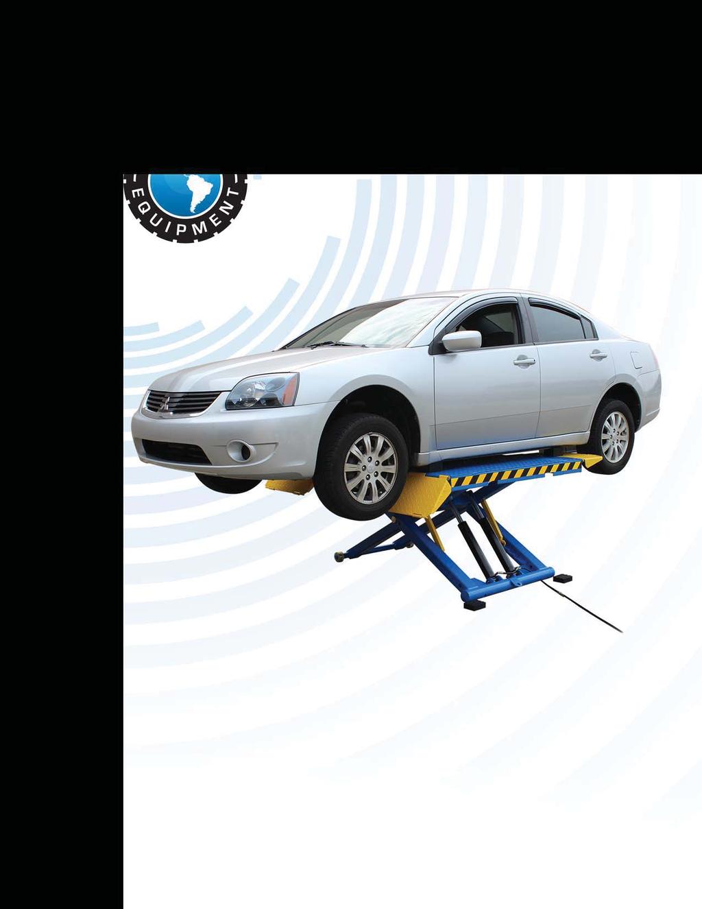
4 Specifications Electric/Hydraulic power system Mechanical safety locks release, no need of air source 2-Dual cylinders are applied to assure lifting smoothly Portable design Movable drive thru ramps and extended platforms accommodate varying wheelbase vehicles Skid proof diamond runway Model Lifting Capacity Lifting Time Raised Height Lowered Height Overall Width Runway Width Runway Length Overall Length with Ramps Gross Weight Motor EM06 2.8T 6,000 lbs 21S 41 3/4 4 1/8 80 3/8 23 5/8 57 1/2 83 7/ lbs 30.HP Fig. 1 Specifications EM06 4
 Pliers Fig.")


5 Installation Requirement Tools Requirement Screw Set English Spanner (12 ) Grease Gun Hook Spanner (40~42mm) Wrench sets (13#, 15#, 17#, 19#) Pliers Fig. 2 Concrete Specifications Failure to follow concrete specifications may result in personal injury and the lift or vehicle falling. 1. Concrete must be a minimum of 4 inches and must be cured before lift installation. 2. Concrete must be in good condition and must have a test strength 3,500psi (250kg/cm²) minimum. 3. Floors must be level and no cracks. Power Supply The power unit must be 1.5 horsepower minimum. Electrical supply must consist of a 30AMP breaker minimum. Power supply comes with a 110 volt cord. Installation Requirement EM06 5

6 Steps Of Installation A. Location Of Installation Check and insure the installation location (concrete, layout, space size etc.) is suitable for lift installation (See Fig. 3). Fig. 3 B. Check The Parts Before Assembly, And Make Sure All The Parts Are Completed 1. Packaged lift, Parts box, Power unit and Power unit stand. Move the parts aside, open the outer packing and check the parts according to the shipment parts list (See Fig. 4). 48 Fig. 4 Steps Of Installation EM06 6


. Fig.")
7 2. Open the parts box, check the parts according to the part list (See Fig. 5). Fig Open the parts bag, check the parts according to the part list (See Fig. 6). Fig. 6 Steps Of Installation EM06 7

8 C. Install Power Unit And Pressure Compensation Valve (See Fig. 7). Pay attention to the installation direction of Pressure compensation valve Fig. 7 Steps Of Installation EM06 8
.")

9 D. Connecting Oil Hoses (See Fig. 8) Fig. 8 Steps Of Installation EM06 9
 1.")
10 E. Install Electrical System Connect the power source on the data plate of power unit. Note: 1. For the safety of operators, the power wiring must contact the floor well. 2. Pay attention to the direction of rotations when using three phases motors. Atlas Single Phase Motor (Fig. 9) 1. Connecting the two power supply lines (fire wire L and zero wire N) to terminals of AC contactor marked L1, L2 respectively. 2. Connecting the two motor wires to terminals of AC contactor marked T1, T2. 3. Connecting L2 to A2 of AC contactor. 4. Connecting two wires of control button to A.C. contactor terminals marked A1, L1. Electric diagram Fig. 9 Steps Of Installation EM06 10

11 Exploded View Fig. 10 Exploded View EM06 11

12 Cylinder Fig. 11 Atlas Manual Power Unit 110V/60HZ Single Phase Fig. 12 Exploded View EM06 12


13 Illustration Of Hydraulic Valve For Atlas Manual Power Unit UP Button Protective Ring Oil Return Port Relief Valve Release valve Oil Outlet Check Valve Release handle Throttle Valve 110V/60HZ/1 phase Fig. 13 Exploded View EM06 13
, and adjust the pressure to 25Mpa with a straight screwdriver.")

14 Operation Instructions 1. Install the oil hose between oil cylinder and power unit, connect the power source wire. 2. Rated pressure adjustment for power unit: unscrew the outer nut of relief valve with a #27 wrench (see Fig. 14), and adjust the pressure to 25Mpa with a straight screwdriver. Turn clockwise to increase pressure, turn counter-clockwise to reduce pressure. Make 1/4 turn each time during adjusting, then re-install the outer nut of relief valve. #27 wrench Outer nut Fig. 14 Straight Screwdriver Counter-clockwise to decrease pressure Fig. 15 Clockwise to increase pressure Fig To raise the lift: Drive the vehicle on to the platform, select the suitable rubber pad. Press the UP button till the lift is raised to the required height and the locks are in engaged status (See Fig. 17), 4. To lower the lift: Press the button UP, until the safety lock is in the released position (See Fig. 18), lower lift by pushing lowering handle. Operation Instructions EM06 14


15 Safety Device in Lock position Fig. 17 Safety Device in release position Fig Move the lift: Raise or lower the lift from 8 to the ground, use power unit stand to move (See Fig. 19). Use power unit stand to move Fig. 19 Operation Instructions EM06 15
 Fig. 20 2.")


16 Maintenance Schedule Monthly 1. Lubricate all moving parts with lubricant (See Fig. 20) Fig Check all connectors, bolts and pins to make sure good connection. 3. Make a visual inspection of all hydraulic tube for wear and oil leak. Every six months 1. Make a visual inspection of all moving parts for possible wear, interference or damage. 2. Check all fastener and re-torque. Maintenance Schedule EM06 16
17 Trouble Shooting TROUBLE CAUSE REMEDY Motor does not run Motor runs but the lift is not raised Lift does not stay up Lift raises slowly Lift can not lower 1. Button does not work 2. Wiring connections are not in good condition 3. Motor burned out 4. Safety Switch is damaged 5. AC contactor burned out 1. Motor runs in reverse rotation 2. Gear Pump out of operation 3. Release Valve in damage 4. Relief Valve or Check Valve in damage 5. Low oil level 6. Overload lifting or low pressure 1. Release Valve out of work 2. Relief Valve or Check Valve leakage 3. Cylinder or Fittings leaks 1. Oil line is jammed 2. Motor running on low voltage 3. Oil mixed with air 4. Gear Pump leaks 5. Overload lifting 1. Safety device are in activated 2. Release Valve in damage 3. Oil system is jammed 1. Replace button 2. Repair all wiring connections 3. Repair or replace motor 4. Replace the Safety Switch 5. Replace AC Contactor 1.Reverse two power wire 2. Repair or replace 3. Repair or replace 4. Repair or replace 5. Fill tank 6. Check load or adjust the pressure Repair or replace 1. Clean the oil line 2. Check Electrical System 3. Fill tank 4. Repair or replace 5. Check load 1. Release the safeties 2. Repair or replace 3. Clean the oil system Trouble Shooting EM06 17
18 Parts List Item Part# Description QTY. (See Fig. 10, Fig. 4, Fig. 7-8) Platform Snap Ring Connecting Shaft for Cylinder Cylinder A Cylinder Base Pin Nylok Nut Washer Washer Upper Scissors Pin Scissors Pin Supper frame(right) Supper frame(left) Inner scissors Washer Safety support assy Safety Pin A Bronze Brush A Washer Roller Split Pin A Slider A Outer Scissor Bracket Shaft Snap Ring Roller for drive in ramp Roller shaft for drive in ramp Snap Ring Nylok Nut Pin for Drive-in Ramp Power unit Drive-in Ramp Rubber Pad Rubber Pad A Oil hose 1 Parts List EM06 18
19 Item Part# Description QTY Straight Fitting Oil Hose T-fitting Oil Hose fitting Wheel dolly Nylok nut Hex bolt Straight fitting 1 44A Two way valve assembly 1 44B Pressure Compensation Valve Straight fitting Washer Plastic wheel Parts Box 1 Parts For Cylinder (See Fig. 11) Item Part# Description QTY A Bore Weldment Piston Rod Bleeding Plug Head cap Dust ring O - Ring O - Ring Piston O-Ring O-Ring Y-Ring Support Ring Nut Greasing Fitting 4 Parts List EM06 19
20 Atlas Manual Power Unit 110V/60HZ/1 Phase (See Fig. 12) Item Part# Description QTY A Motor Protective Ring AC contactor A Motor Connecting Shaft A Valve Body A Relief Valve Throttle Valve A Lock Washer A Socket Bolt A Oil Inlet Pipe A O- Ring A Filter A Socket Bolt A Reservoir A Screw with Washer A Cover of Capacitor A Start Capacitor A A Running Capacitor A Rubber Gasket A Cup head bolt with Washer A Cover of Motor Terminal Box A Button switch A Oil Return Port A Oil Outlet A Check Valve A Release valve A Release valve handle A Washer A Hex bolt A Gear Pump A Oil Return Pipe A Filler Cap 1 Parts List EM06 20

21 Warranty This item is warranted for two (2) years on structural components and one (1) year on air or electric hydraulic power units, pneumatic power units, cylinders and major components from date of invoice. Wear items are covered by a 90 day warranty. This LIMITED warranty policy does not include a labor warranty. NOTE: ALL WARRANTY CLAIMS MUST BE PRE-APPROVED BY THE MANUFACTURER TO BE VALID. The Manufacturer shall repair or replace at their option for this period those parts returned to the factory freight prepaid, which prove after inspection to be defective. This warranty will not apply unless the product is installed, used and maintained in accordance with the Manufacturers installation, operation and maintenance instructions. This warranty applies to the ORIGINAL purchaser only, and is non-transferable. The warranty covers the products to be free of defects in material and workmanship but, does not cover normal maintenance or adjustments, damage or malfunction caused by: improper handling, installation, abuse, misuse, negligence, carelessness of operation or normal wear and tear. In addition, this warranty does not cover equipment when repairs or alterations have been made or attempted to the Manufacturer s products. THIS WARRANTY IS EXCLUSIVE AND IS LIEU OF ALL OTHER WARRANTIES EXPRESSED OR IMPLIED INCLUDING ANY IMPLIED WARRANTY OR MERCHANTABILITY OR ANY IMPLIED WARRANTY OF FITNESS FROM A PARTICULAR PURPOSE, AND ALL SUCH IMPLIED WARRANTIES ARE EXPRESSLY EXCLUDED. THE REMEDIES DESCRIBED ARE EXCLUSIVE AND IN NO EVENT SHALL THE MANUFACTURER, NOR ANY SALES AGENT OR OTHER COMPANY AFFILIATED WITH IT OR THEM, BE LIABLE FOR SPECIAL CONSEQUENTIAL OR INCIDENTAL DAMAGES FOR THE BREACH OF OR DELAY IN PERFORMANCE OF THIS WARRANTY. THIS INCLUDES, BUT IS NOT LIMITED TO, LOSS OF PROFIT, RENTAL OR SUBSTITUTE EQUIPMENT OR OTHER COMMERCIAL LOSS. PRICES: Prices and specifications are subject to change without notice. All orders will be invoiced at prices prevailing at time of shipment. Prices do not include any local, state or federal taxes. RETURNS: Products may not be returned without prior written approval from the Manufacturer. DUE TO THE COMPETITIVENESS OF THE SELLING PRICE OF THESE LIFTS, THIS WARRANTY POLICY WILL BE STRICTLY ADMINISTERED AND ADHERED TO. Warranty EM06 21
Read this entire manual before operation begins.
 Read this entire manual before operation begins. Record below the following information which is located on the serial number data plate. Serial No. Model No. Date of Installation Contents Specifications.............
Read this entire manual before operation begins.
 Read this entire manual before operation begins. Record below the following information which is located on the serial number data plate. Serial No. Model No. Date of Installation Contents Specifications.............
Read this entire manual before operation begins.
 Read this entire manual before operation begins. Record below the following information which is located on the serial number data plate. Serial No. Model No. Date of Installation Contents Specifications.............
Read this entire manual before operation begins.
 Read this entire manual before operation begins. Record below the following information which is located on the serial number data plate. Serial No. Model No. Date of Installation Contents Specifications.............
Read this entire manual before operation begins.
 Read this entire manual before operation begins. Record below the following information which is located on the serial number data plate. Serial No. Model No. Date of Installation Contents Specifications.............
Atlas PV-9WP Addendum
 Atlas PV-9WP Addendum 9,000 lb. Capacity Two-Post Overhead Lift The Atlas PV-9WP above ground hoist is 6 inches wider than the Atlas PV-9P, giving it an overall width of 141 (11 9 ) and a drive thru width
Read this entire manual before operation begins.
 Rev. 12/12/2017 Read this entire manual before operation begins. Record below the following information which is located on the serial number data plate. Serial No. Model No. Date of Installation Contents
PRO JACK 4500 ROLLING BRIDGE JACK 4,500 POUND CAPACITY. PARTS MANUAL P/n NRJ450BK
 PRO JACK 4500 ROLLING BRIDGE JACK 4,500 POUND CAPACITY PARTS MANUAL P/n NRJ450BK 2007 RJ-45 (M) PARTS LIST Item # Part Number Description Qty 1 NRJ45-1000 Bottom Tray 1 2 NRJ45-2100 Outer Scissor 1 3
CONTENTS. Product Features and Specifications...1. Installation Requirement Steps of Installation.. 5. Exploded View Test Run...
 CONTENTS Product Features and Specifications...1 Installation Requirement... 3 Steps of Installation.. 5 Exploded View...18 Test Run...21 Operation Instruction...22 Maintenance... 23 Trouble Shooting...
CONTENTS. Product Features and Specifications Installation Requirement Steps of Installation 4. Exploded View Test Run...
 CONTENTS Product Features and Specifications... 1 Installation Requirement... 3 Steps of Installation 4 Exploded View... 14 Test Run... 16 Operation Instruction... 19 Maintenance... 20 Trouble Shooting...
CONTENTS. Product Features and Specifications...1. Installation Requirement Steps of Installation.. 5. Exploded View Test Run...
 CONTENTS Product Features and Specifications...1 Installation Requirement... 4 Steps of Installation.. 5 Exploded View...21 Test Run...26 Operation Instruction...27 Maintenance... 28 Trouble Shooting...
CONTENTS. Product Features and Specifications Installation Requirement Installation Exploded View Operation Instruction...
 1 CONTENTS Product Features and Specifications... 3 Installation Requirement... 5 Installation... 6 Exploded View... 20 Test... 22 Operation Instruction... 25 Maintenance... 26 Trouble Shooting... 27 Parts
30-SS1203A 12,000 LB CAPACITY SCISSOR ALIGNMENT LIFT INSTALLATION AND SERVICE MANUAL P/N:
 WITH STRENGTH 30-SS1203A 12,000 LB CAPACITY SCISSOR ALIGNMENT LIFT INSTALLATION AND SERVICE MANUAL P/N: 420-02553 CONTENTS Product Features and Specifications...1 Installation Requirement...3 Steps of
CONTENTS. Product Features and Specifications...1. Installation Requirement...3. Steps of Installation...4. Exploded View Test Run...
 TP10AS 2-POST LIFT CONTENTS Product Features and Specifications...1 Installation Requirement...3 Steps of Installation...4 Exploded View...24 Test Run....28 Operation Instruction...29 Maintenance...30
Installation/Operation/Service Manual
 TLX12/TLX12A Installation/Operation/Service Manual CONTENTS Product Features and Specifications...1 Installation Requirement...3 Steps of Installation...4 Exploded View...23 Test Run...28 Operation Instruction...29
ASSEMBLY / OPERATION INSTRUCTIONS. Low Profile Motorcycle Dolly
 ASSEMBLY / OPERATION INSTRUCTIONS 1,500LB CAPACITY Low Profile Motorcycle Dolly Model: 03-CG1500-01(B1) WARNING BEFORE USE PLEASE READ ALL WARNINGS AND INSTRUCTIONS TO PREVENT SERIOUS INJURY Drop-Tail
ASSEMBLY / OPERATION INSTRUCTIONS. Low Profile / Stand-Up Motorcycle Dolly
 ASSEMBLY / OPERATION INSTRUCTIONS 1,500LB CAPACITY Low Profile / Stand-Up Motorcycle Dolly Model: 03-CGPR1500-01(C) WARNING BEFORE USE PLEASE READ ALL WARNINGS AND INSTRUCTIONS TO PREVENT SERIOUS INJURY
Read this entire manual before operation begins.
 Read this entire manual before operation begins. Record below the following information which is located on the serial number data plate. Serial No. Model No. Date of Installation Contents Specifications.............
Operating Instructions and Parts Manual SLT-330F Scissor Lift Table
 Operating Instructions and Parts Manual SLT-330F Scissor Lift Table For serial no. 17020001 and higher JET 427 New Sanford Road LaVergne, Tennessee 37086 Part No. M-140771 Ph.: 800-274-6848 Revision C
Read this entire manual before operation begins.
 Revised 9/5/2018 Read this entire manual before operation begins. Record below the following information which is located on the serial number data plate. Serial No. Model No. Date of Installation Contents
MODEL EF Full Circle Tire Spreader
 MODEL EF Full Circle Tire Spreader Installation, Operation & Repair Parts Information Branick Industries, Inc. 4245 Main Avenue P.O. Box 1937 Fargo, North Dakota 58103 REV. 062917 P/N: 81-0050C CAUTION
MODEL 5120 Tire Repair Station
 MODEL 5120 Tire Repair Station 00-0049 Installation, Operation & Repair Parts Information Branick Industries, Inc. 4245 Main Avenue P.O. Box 1937 Fargo, North Dakota 58103 REV01182017 P/N: 81-0058G CAUTION
Pump/Manifold Kits. Instructions F ENG. To convert E-Flo 4-Ball Piston Pumps to a different size lower. For professional use only.
 Instructions Pump/Manifold Kits 311611F ENG To convert E-Flo 4-Ball Piston Pumps to a different size lower. For professional use only. See page 2 for a list of available kits. Important Safety Instructions
ATD-7391A 10-Ton Long Chassis Service Jack Owner s Manual
 ATD-7391A 10-Ton Long Chassis Service Jack Owner s Manual Specifications Features: Made in China to ATD Tools, Inc. Specifications Visit us at www.atdtools.com ATD7391A_rev_0318 NOTE: 1. SAFETY maintenance.
Operating Instructions and Parts Manual Long Chassis Service Jacks
 Operating Instructions and Parts Manual Long Chassis Service Jacks Models JSJ-3T/JSJ-5T/JSJ-10T WMH TOOL GROUP 2420 Vantage Drive Elgin, Illinois 60123 Part No. M-454430 Ph.: 800-274-6848 Revision A 8/05
INSTALLATION AND SERVICE MANUAL
 INSTALLATION AND SERVICE MANUAL Please fill in for future reference: MODEL: SERIAL NUMBER: DATE PURCHASED: * Please fill out the warranty registration card in this manual or online at www.mdminc.com XXXXXXXXX
203 TRANSFER CASE CONVERSION
 203 TRANSFER CASE CONVERSION PN:501 OUR FOUR TRANSFER CASE WEDGES REPLACE THE SPIDER GEARS AND CONNECT THE PLANETARY GEAR AND REAR OUTPUT SHAFT MAKING ONE UNIT. SIMILAR IN DESIGN & FUNCTION TO THE BEST
Benron Equipment & supply, Inc.
 Benron Equipment & supply, Inc. Service Manual G5 Part Number 6-00A. and 6-00M Edition 0/008 Ez-Tex G5 Operational Instructions. Before attempting to use the G5 check material manufacturer for mixing and
Models PR-12F PR-12C PR-15C SURFACE MOUNTED TWO-POST LIFTS INSTALLATION AND OPERATION MANUAL
 Forward this manual to all operators. Failure to operate this equipment as directed may cause injury. INSTALLATION AND OPERATION MANUAL SURFACE MOUNTED TWO-POST LIFTS Models PR-12F PR-12C PR-15C Keep this
Stainless Steel Air Motor Conversion Kits
 Instructions Stainless Steel Air Motor Conversion Kits 096B Conversion Kit 650 For 00 Pumps Conversion Kit 65 For 590 Pumps Conversion Kit 65 For 50 Pumps Model 650 Model 65 Model 65 Graco Inc. P.O. Box
FLEETWOOD TRAVEL TRAILER SLIDEOUT SYSTEM OWNER S MANUAL
 FLEETWOOD TRAVEL TRAILER SLIDEOUT SYSTEM OWNER S MANUAL 82-S0150-01 REV. 1 April, 2002 TABLE OF CONTENTS PAGE # OPERATIONS MANUAL... 1 1. SYSTEM DESCRIPTION... 1 1.1 MAJOR COMPONENTS... 1 2. HOW TO OPERATE
1300 lb Capacity Trike Lift
 M-1300C-TRIKE 1300 lb Capacity Trike Lift USER S MANUAL TRIKE MOTORCYCLE LIFT An extra wide platform designed especially for three-wheel motorcycles. M-1300-TRIKE Trike Motorcycle Lift SPECIFICATIONS:
HSB21 Battery Burnisher
 HSB21 Battery Burnisher OPERATION AND PARTS MANUAL Rev A 01/2003 HS2100 PARTS LIST Item No. Qty Part No. Description 1 1 001 Lower Body Housing 2 1 002 Battery Condition Meter 3 1 003 RPM Meter 4 1 004
HP30 Slab Saw Owner s Manual and Operating Instructions
 HP30 Slab Saw Owner s Manual and Operating Instructions MADE IN USA Revision 07 09.0 Manual Part No. 67 Caution: Read all safety and operating instructions before using this equipment. This manual MUST
Stainless Steel Air Motor Conversion Kits
 Instructions Stainless Steel Air Motor Conversion Kits 096D Conversion Kit 650 For 00 Pumps Conversion Kit 65 For 590 Pumps Conversion Kit 65 For 50 Pumps Model 650 Model 65 Model 65 Installation Pressure
Raydot LLC 24 Actuator (115 VOLT)
") Installation, Operation & Parts Manual Read carefully the information provided. Retain manual for future reference. Raydot LLC 24 Actuator (115 VOLT) 145 Jackson Ave. S. Cokato, MN 55321-USA (320) 286-2103
Installation, Operation & Parts Manual Read carefully the information provided. Retain manual for future reference. Raydot LLC 24 Actuator (115 VOLT) 145 Jackson Ave. S. Cokato, MN 55321-USA (320) 286-2103
ASSEMBLY & OPERATION INSTRUCTION MANUAL
 LR-26-PAD 6000 lb Capacity Low-Rise Pad Lift ASSEMBLY & OPERATION INSTRUCTION MANUAL 6,000 LB. LOW-RISE PAD LIFT Easy frame lifting on padded runways. Great for wheel and brake work, tire and wheel changing
Air Actuated Hydraulic Bottle Jacks
 Air Actuated Hydraulic Bottle Jacks Operating Instructions & Parts Manual Model Number Atd-7412 Atd-7420 Capacity 12 Ton 20 Ton Atd Tools Inc. 160 Enterprise Drive, Wentzville MO 63385 Printed in China
Model , Series A 9 in. (23 cm) roller frame with 45 angle and 12 in. reach 1/2 in. (13 mm) nap roller cover
 roller frame with 45 angle and 12 in. reach 1/2 in. (13 mm) nap roller cover") Operating Instructions 309899 Rev. A This manual contains important warnings and information. READ AND KEEP FOR REFERENCE. INSTRUCTIONS Manufactured by Model 246818, Series A 9 in. (23 cm) roller frame
Operating Instructions 309899 Rev. A This manual contains important warnings and information. READ AND KEEP FOR REFERENCE. INSTRUCTIONS Manufactured by Model 246818, Series A 9 in. (23 cm) roller frame
Heliporter. Owner s Manual. H250 Series. By Paravion Technology, Inc. Copyright 2017 Paravion Technology, Inc.
 By, Owner s Manual H250 Series Copyright 2017, Introduction Congratulations, you have purchased one of the finest helicopter ground handling vehicles on the market today. We at, have strived to engineer
Pro Shot Grease Dispense Valve
 Instructions Parts List Pro Shot Grease Dispense Valve 309032J For high pressure grease dispense. 8000 psi (55 MPa, 552 bar) Maximum Working Pressure Model No. 242055, Series B, 1/4 npt Fluid Inlet Model
Hydraulic Clutch Jack
 Hydraulic Clutch Jack Operating Instructions & Parts Manual Model Number Atd-7404 Capacity 500 Lb. Atd Tools Inc. 160 Enterprise Drive, Wentzville MO 63385 Printed in China ATD7404-M0 05/07 Save these
ASM Maxi Poles. Instruction-Parts B Series. For the application of architectural paints and coatings.
 Instruction-Parts ASM Maxi Poles 312483B For the application of architectural paints and coatings. 3400 Series 4050 psi (27.92 MPa, 280 bar) Maximum Working Pressure Important Safety Instructions Read
OWNER'S MANUAL SLT-330F Scissor Lift Table
 OWNER'S MANUAL SLT-330F Scissor Lift Table JET EQUIPMENT & TOOLS, INC. P.O. BOX 1349 Phone:253-351-6000 A WMH Company Auburn, WA 98071-1349 Fax: 1-800-274-6840 www.jettools.com e-mail jet@jettools.com
Heliporter. Owner s Manual. 150 Series. by Paravion Technology, Inc.
 Heliporter by Paravion Technology, Inc. Owner s Manual 150 Series Introduction Congratulations, you have purchased one of the finest helicopter ground handling vehicles on the market today. We at Paravion
HEAVY DUTY TROLLEY JACK. Operation Manual
 HEAVY DUTY TROLLEY JACK 4T Operation Manual Make sure to read and fully understand the instruction manual before using this product and keep the manual properly 1 General Description Product Description
24 Linear Actuator 115 Volts A.C. (Cat. # C430A)
") Installation, Operation & Parts Manual Read carefully the information provided. Retain manual for future reference. 24 Linear Actuator 115 Volts A.C. (Cat. # C430A) Page 1 of 8 IS10007.doc 11/15/06 IMPORTANT!
Installation, Operation & Parts Manual Read carefully the information provided. Retain manual for future reference. 24 Linear Actuator 115 Volts A.C. (Cat. # C430A) Page 1 of 8 IS10007.doc 11/15/06 IMPORTANT!
15H882 Slider Bearing Kit
 Instructions 15H882 Slider Bearing Kit 311616D ENG To replace slider bearings on E-Flo 4-Ball Piston Pumps. For professional use only. Important Safety Instructions Read all warnings and instructions in
24G621 Agitator Speed Controller Accessory
 Instructions-Parts 24G62 Agitator Speed Controller Accessory 3A35A ENG Accessory kit to control and automatically maintain the speed of an air-powered agitator. For professional use only. Important Safety
Model BP6150. Triplex Ceramic Plunger Pump Operating Instructions/ Manual
 Model BP6150 Triplex Ceramic Plunger Pump Operating Instructions/ Manual Contents: Installation Instructions: page 2 Pump Specs: page 3 Exploded View: page 4 Parts List / Kits Torque Specifications: page
Proportioning Unit evolution G-125 A / G-200 A
 Proportioning Unit evolution G-125 A / G-200 A Issue 4.2 20/05/13 Ref. NR-00007-ENG Before installing the unit and starting it up, carefully read all the technical and safety documentation included in
SLAB SAW SERIES PARTS LIST
 SLAB SAW SERIES PARTS LIST MODELS: HP Part# 020 HP20 Part# 02020 HP2 Part# 0202 MADE IN USA MADE IN USA Revision 09.20 Manual Part No. 6269 Caution: Read all safety and operating instructions before using
Dodge SpynTec Hub Conversion Kit
 SpynTec SpynTec Industries Installation Instructions for the Dodge SpynTec Hub Conversion Kit I n d u s t r i e s SpynTec Industries LLC. 11501 South Avenue North Lima, Ohio 4445 1.888.90.AXLE Page 1 Warning
iqpc912 PARTS MANUAL PC912PM v1
 iqpc912 PARTS MANUAL PC912PM v1 See Page 10 See Page 6 & See Page 12 See Page 2 See Page 16 See Page 1 See Page 1 See Page See Page 22 See Page 20 See Page 2 See Page 26 3 16 19 1 17 1 1 11 13 12 10 9
Pressure Roller with 24-inch Fixed Extension - For application of architectural paints and coatings -
 Instructions Important Safety Instructions Read all warnings and instructions in this manual. Save these instructions. 311082D Pressure Roller with 24-inch Fixed Extension - For application of architectural
Pneumatic Cylinder 14 Bore X 22 Stroke Part No. R (Formerly P )
") Pneumatic Cylinder 14 Bore X 22 Stroke Part No. R434001268 (Formerly P -193419-00003) Service Information INSTALLATION Before installing this cylinder, all air lines in the system should be blown clean
Pneumatic Cylinder 14 Bore X 22 Stroke Part No. R434001268 (Formerly P -193419-00003) Service Information INSTALLATION Before installing this cylinder, all air lines in the system should be blown clean
MODEL TON HYDRAULIC FLOOR JACK
 MODEL 66510 10 TON HYDRAULIC FLOOR JACK USER'S MANUAL *This hydraulic jack conforms to all "ANSI / ASME" safety standards. Jackco Transnational Inc. 2010 South El Monte, CA 888-452-2526 To see more jackco
DISCONTINUED VERSION Parts listed in this catalog may no longer be available. ILLUSTRATED PARTS CATALOG BUNN-O-MATIC CORPORATION
 8 4 0 0 1 BUNN Espress ES 2C DISCONTINUED VERSION Parts listed in this catalog may no longer be available. 12 0,5 1,5 CL 2 16 2,5 CAUTION HOT Liquid-Steam-Surfaces OFF ON ILLUSTRATED PARTS CATALOG Designs,
MODEL TON HYDRAULIC FLOOR JACK
 MODEL 66500 5 TON HYDRAULIC FLOOR JACK USER'S MANUAL *This hydraulic jack conforms to all "ANSI / ASME" safety standards. Jackco Transnational Inc. 2010 South El Monte, CA 888-452-2526 To see more jackco
POWER GEAR SLIDE-OUT MANUAL
 POWER GEAR SLIDE-OUT MANUAL Operation Guide FLUSH FLOOR SLIDE-OUT SYSTEM FOR AMERICAN COACH PRODUCTS 82-S0220-01 Rev. 1 AMERICAN COACH SLIDE-OUT MANUAL FLUSH FLOOR SYSTEM TABLE OF CONTENTS SECTION PAGE
Electric Actuator Installation, Operation & Maintenance Manual
 ICI Indelac Controls, Inc. Electric Actuator Installation, Operation & Maintenance Manual 6810 Powerline dr.-florence, Ky. 41042 - Telephone 859-727-7890, Tool free 800-662-9424 Fax. 859-727-4070, e-mail:
ATD-7384W 12-Ton Bottle Jack Owner s Manual
 ATD-7384W 12-Ton Bottle Jack Owner s Manual Features: Specifications Made in China to ATD Tools, Inc. Specifications Visit us at www.atdtools.com ATD7384W_rev_0118 Product Description NOT Safety Precautions
Operating Instructions & Parts Manual. Air/Manual Hydraulic Bottle Jacks
 J18124-M1_032015 Operating Instructions & Parts Manual Air/Manual Hydraulic Bottle Jacks Model J18124 J18204 Capacity 12 Ton 20 Ton U.S. Patent Nos. 6,012,377-5,946,912! This is the safety alert symbol.
Mini Jacks Instruction Manual
 J11050-M0_062017 Instruction Manual MODELS: J11050, J11055-5 Ton Capacity J11100-10 Ton Capacity J11200-20 Ton Capacity This is the safety alert symbol. It is used to alert you to potential personal injury
USER MANUAL. NEMA 48C Flange Mounted, Enclosed, Clutch Brake. FMCBE Model 500 FORM NO. L A (i)
") USER MANUAL NEMA 48C Flange Mounted, Enclosed, Clutch Brake FMCBE Model 500 (i) In accordance with Nexen s established policy of constant product improvement, the specifications contained in this manual
USER MANUAL NEMA 48C Flange Mounted, Enclosed, Clutch Brake FMCBE Model 500 (i) In accordance with Nexen s established policy of constant product improvement, the specifications contained in this manual
CDS-JOHN BLUE COMPANY
 VRH-1000 HYDRAULIC VARIABLE RATE DRIVE AND MOUNT KIT PARTS AND INSTRUCTION MANUAL CDS-JOHN BLUE COMPANY DIVISION OF ADVANCED SYSTEMS TECHNOLOGY, INC. 290 Pinehurst Drive - Huntsville, Alabama 35806 P.O.
Replace This With Cover PDF
 Replace This With Cover PDF Read this entire manual before operation begins. Record below the following information which is located on the serial number data plate. Serial No. Model No. Date of Installation
Flowmaster K67/K69 Series Sanitary Air-Actuated Valve OPERATION MAINTENANCE & PARTS LIST
 Flowmaster K67/K69 Series Sanitary AirActuated Valve OPERATION MAINTENANCE & PARTS LIST GENERAL INSTRUCTIONS DISASSEMBLY AND REASSEMBLY This manual contains disassembly and reassembly instructions with
500kg HYDRAULIC TABLE LIFT
 Product Code: 6007T OWNER S MANUAL PRODUCT CODE: 6007T 500kg HYDRAULIC TABLE LIFT Working Load Limit 500kg Maximum Height 1575mm Minimum Height 440mm Table Dimensions 1010x520mm Wheel Diameter 150mm Made
CRD600 Automatic Fitting Inserter
 CRD600 Automatic Fitting Inserter OPERATIONS MANUAL VERSION 2.3 LAST EDITED 12.07.2018 cleanroomdevices.com 1 Table of Contents Title Page.. 1 Table of Contents. 2 1.0 General Product & Safety Information...3
PVI 1800/PVI Residential/Commercial Grid-Tied Photovoltaic Inverter WARRANTY MANUAL. Subject to Change REV , Solectria Renewables
 PVI 1800/PVI 2500 WARRANTY MANUAL Residential/Commercial Grid-Tied Photovoltaic Inverter 2009, Solectria Renewables Subject to Change REV 10.09 1 Product Warranty & RMA Policy 1.1 Warranty Policy The Solectria
HP14 Slab Saw Owner's Manual and Operating Instructions
 Slab Saw Owner's Manual and Operating Instructions MADE IN USA Revision 112 09.2018 Manual Part No. 1771 Caution: Read all safety and operating instructions before using this equipment. This manual MUST
GA-160 Gas Amplifier
 GA-160 Gas Amplifier INSTALLATION, OPERATION & MAINTENANCE MANUAL INTERFACE DEVICES, INC. 230 Depot Road, Milford, CT 06460 Ph: (203) 878-4648, Fx: (203) 882-0885, E-mail: info@interfacedevices.com www.interfacedevices.com
CRD610 Automatic Fitting Inserter
 CRD610 Automatic Fitting Inserter OPERATIONS MANUAL VERSION 1.2 LAST EDITED 12.12.2018 cleanroomdevices.com 1 Table of Contents Title Page. 1 Table of Contents...2 1.0 General Product & Safety Information....3
4-Ton Electric Log Splitter
 4-Ton Electric Log Splitter Questions: Support@Powrkraft.com PK65556 2 18ga. @ 20ft, 16ga. @ 50ft, 14 ga. @ 75ft. 12ga @ 100ft, 10ga @ 200ft These are minimum cord requirements. 13-16 Model Number 65556
MODEL 5500 Tire Repair Station
 MODEL 5500 Tire Repair Station Installation, Operation and Repair Parts Information Branick Industries, Inc. 4245 Main Ave P.O. Box 1937 Fargo, North Dakota 58103 P/N: 81-0047C TABLE OF CONTENTS SAFETY
PREMIER, MARINE, & STANDARD
 INSTA LLATION INSTRUCTION AND SERVICE MANUAL I TITAN 12" x 2" BRAKES FREE BACKING. UNI-SERVO. DUO-SERVO PREMIER, MARINE, & STANDARD Limited Warranty TITAN Inc. ("TITAN') warrants its products to be free
Straight-Bore Clutch LSCC-32, 44, 54
 Straight-Bore Clutch LSCC-32, 44, 54 1 In accordance with Nexen s established policy of constant product improvement, the specifications contained in this manual are subject to change without notice. Technical
Grapple Kit Install & Grapple Bucket Manual
 Grapple Kit Install & Grapple Bucket Manual Model # Serial # Rev. 10/13 Rylind Manufacturing, Inc. 2801 Youngfield St Suite 250 Golden, CO 80401 Business/Sales Offices: 303-979-3548 Manufacturing Plant:
OPERATIONS AND MAINTENANCE
 HELITILT OPERATIONS AND MAINTENANCE JB ATTACHMENTS - WHEN ONLY THE BEST WILL DO! INCREASE PRODUCTIVITY PROFITABILITY VERSATILITY CONTENTS 1.0 INTRODUCTION 1.0-1.4 2.0 SAFETY INSTRUCTIONS 2.0-2.5 3.0 STANDARDS
Operator s Manual. Nitro 1000 Nitro 1000X. Nitro 750 Nitro 750X. September REV0
 Operator s Manual Nitro 750 Nitro 750X Nitro 1000 Nitro 1000X September.27.2018REV0 Table of Contents Introduction...3 Safety.....4 Equipment Requirements......5 What You Have Received. 5 Serial Number...6
LUBRICATOR GUN INSTRUCTIONS-PARTS LIST. 10,000 psi (700 bar) Maximum Delivery Pressure. Detachable-type
 Maximum Delivery Pressure. Detachable-type") INSTRUCTIONS-PARTS LIST 306 460 INSTRUCTIONS This manual contains important warnings and information. READ AND KEEP FOR REFERENCE. Rev. E Supercedes D Detachable-type LUBRICATOR GUN 10,000 psi (700 bar)
INSTRUCTIONS-PARTS LIST 306 460 INSTRUCTIONS This manual contains important warnings and information. READ AND KEEP FOR REFERENCE. Rev. E Supercedes D Detachable-type LUBRICATOR GUN 10,000 psi (700 bar)
Fast Lift Service Jack, Low Profile
 Blackhawk Automotive is a Licensed Trade Mark Made by SFA Companies, Kansas City, MO Fast Lift Service Jack, Low Profile Operating Instructions & Parts Manual Model BH6023B Capacity 2 Ton! U.S. Patent
RPD SERIES HEAVY AND SEVERE DUTY SNOW PLOW
 RPD SERIES HEAVY AND SEVERE DUTY SNOW PLOW Model: Serial Number: Rev. 01/14 Rylind Manufacturing, Inc. 2801 Youngfield St Suite 250 Golden, CO 80401 Main Offices: 303-979-3548 Manufacturing Plant: 970-522-2859
GETZ EQUIPMENT INNOVATORS PART NO.: 3G59419 MODEL: BV 101 P PNEUMATIC BELT VISE WITH EXTENDED BELT & ROLLER
 GETZ EQUIPMENT INNOVATORS PART NO.: 3G59419 MODEL: BV 101 P PNEUMATIC BELT VISE WITH EXTENDED BELT & ROLLER 2320 Lakecrest Drive, Pekin IL 61554 PH. (888) 747-4389 Fax (309) 495-0625 Website: www.getzequipment.com
3 Station Bike Rack Organization Center
 H O L D I N G S, L L C 3 Station Bike Rack Organization Center Model No.: SBR300 This manual is designed to ensure that your new bike rack can be assembled successfully. Most people find that by setting
Installation Instructions / Warranty
 Installation Instructions / Warranty Citterio 39136XX1 39156XX1 Citterio 39236XX1 Axor Citterio Widespread Lav Mixer 39136XX1 Axor Citterio Bidet Mixer 39236XX1 39136XX1 User instructions Turn the right
Elgin Hydraulic Clutch-Brake ECB-240, Product Number FORM NO. L F FORM NO. L F-0704
 Elgin Hydraulic Clutch-Brake ECB-20, Product Number 96225 FORM NO. L-20283-F-070 1 FORM NO. L-20283-F-070 In accordance with Nexen s established policy of constant product improvement, the specifications
9' & 12' CHALLENGER SHUFFLEBOARD TABLE ASSEMBLY INSTRUCTIONS
 9' & 12' CHALLENGER SHUFFLEBOARD TABLE ASSEMBLY INSTRUCTIONS NG1205 / NG1210 / NG1212 / NG1214 THANK YOU! Thank you for purchasing this product. We work around the clock and around the globe to ensure
Installation and Maintenance Instructions
 Limited One Year Warranty T&S warrants to the original purchaser (other than for purposes of resale) that such product is free from defects in material and workmanship for a period of one (1) year from
TERMS OF USE TERMS AND CONDITIONS. Plumbing and Heating Products (PL-WR)
") TERMS OF USE 1. Watts pricing and product data is subject to change without notice and such changes supersede all previous versions. 2. Watts data is to be used as provided. Watts is not responsible for
TERMS OF USE 1. Watts pricing and product data is subject to change without notice and such changes supersede all previous versions. 2. Watts data is to be used as provided. Watts is not responsible for
MSC-6KLP Low Profile Mobile Single Column Lift. 6,000 lb. Capacity (1,500 lbs. Max Capacity per Arm) Installation & Operation Manual
 Installation & Operation Manual") Low Profile Mobile Single Column Lift 6,000 lb. Capacity (1,500 lbs. Max Capacity per Arm) Installation & Operation Manual INDEX PREFACE-------------------------------------------------------------------------------
Low Profile Mobile Single Column Lift 6,000 lb. Capacity (1,500 lbs. Max Capacity per Arm) Installation & Operation Manual INDEX PREFACE-------------------------------------------------------------------------------
Hydraulic Wheel Dolly
 Hydraulic Wheel Dolly Operating Instructions & Parts Manual Model Number HW93765 Capacity 3/4 Ton Made in the U.S.A. This is the safety alert symbol. It is used to alert you to potential personal injury
LIFT NAME PART NUMBER SETBACK (min) SETBACK (max)
 SETBACK (max)") Revolution 9889 Garrymore Ln Missoula, MT 59808 888-687-3552 +1-406-549-0769 www.aquacreek.com Wheelchair Attachment PART #: F-705S3 WEIGHT CAPACITY: 350 POUNDS - STANDARD REVOLUTION 300 POUNDS - DEEP
Revolution 9889 Garrymore Ln Missoula, MT 59808 888-687-3552 +1-406-549-0769 www.aquacreek.com Wheelchair Attachment PART #: F-705S3 WEIGHT CAPACITY: 350 POUNDS - STANDARD REVOLUTION 300 POUNDS - DEEP
ABRASIVE BLAST CABINET
 Model 272635 (KERNEL) ABRASIVE BLAST CABINET ( 350L ) ASSEMBLY & OPERATION INSTRUCTION (2 nd version) Jan. 2016 1 / 9 PRODUCT LIMITED WARRANTY The product is guaranteed for 12 months from date of manufacturer
OPERATORS MANUAL/INSTRUCTIONS/PARTS & SERVICE FOR MANUAL & ELECTRIC
 OPERATORS MANUAL/INSTRUCTIONS/PARTS & SERVICE FOR MANUAL & ELECTRIC TABLE OF CONTENTS SAFETY DELIVERY INSPECTION OPERATION 4 MAINTENANCE 5 TROUBLE SHOOTING 5 PARTS 6-15 Frame Scissor Assembly 6-7 Thrust
CLEAN ROOM DEVICES, LLC "WHERE TUBING AND FITTINGS COME TOGETHER"
 CLEAN ROOM DEVICES, LLC "WHERE TUBING AND FITTINGS COME TOGETHER" CRD600 Automatic Fitting Inserter OPERATIONS MANUAL VERSION 2.1 LAST EDITED 7.25.14 DOCUMENT NUMBER 001 cleanroomdevices.com 1 Table of
Operating Instructions & Parts Manual. Oil Control Gun. Models 48UJ82, 48UJ83, 48UJ84, 48UJ85 and 48UJ86
 Operating Instructions & Parts Manual EN Oil Control Gun Models 48UJ82, 48UJ83, 48UJ84, 48UJ85 and 48UJ86 PLEASE READ AND SAVE THESE INSTRUCTIONS. READ CAREFULLY BEFORE ATTEMPTING TO ASSEMBLE, INSTALL,
4000SS. For other repair kits and service parts, send for Ames Repair Parts Price List, PL-A-RP-BPD.
 Series 4000SS RP/IS-A-4000SS 4000SS Reduced Pressure Zone Assemblies Sizes: 8" 10" (200 250mm) Installation Service Repair Kits Maintenance For other repair kits and service parts, send for Ames Repair
ASSEMBLY & OPERATION INSTRUCTION MANUAL
 Sliding Bridge Jack 3,500 lbs. Capacity ASSEMBLY & OPERATION INSTRUCTION MANUAL TABLE OF CONTENTS Specifications... 2 Description & Features... 3 Installation Instructions... 4 Safety Instructions... 4