Read this entire manual before operation begins.
|
|
|
- Hugh Heath
- 5 years ago
- Views:
Transcription

1
2 Read this entire manual before operation begins. Record below the following information which is located on the serial number data plate. Serial No. Model No. Date of Installation
3 Contents Specifications Installation Requirement Steps Of Installation Exploded View Test Run Operation Instructions Maintenance Schedule Trouble Shooting OHSC Parts List Warranty
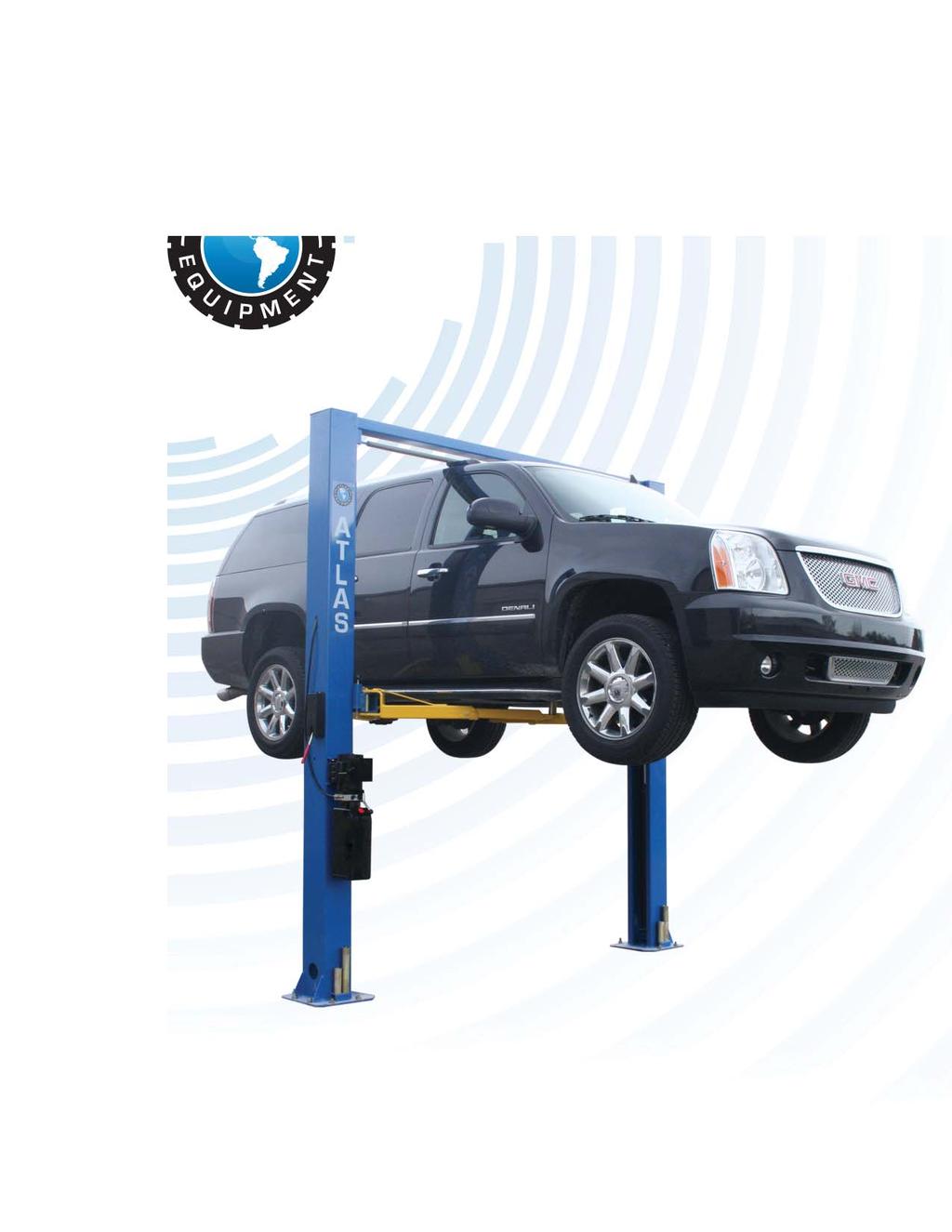
4 Specifications 9-OHSC Clear Floor, Chain-Drive Features Dual hydraulic cylinders designed and made to ANSI standard, utilizing NOK oil seal in cylinder. Self-lubricating UHMW Polyethylene sliders and bronze bush. Single-point safety release, and dual safety design. Clear floor design, provide unobstructed floor space. Overhead safety shutoff device. Super symmetric arm design with 3-stage front arms and 2-stage rear arms. Rubber lift pads with 1.5 and 2.5 stackable extension adaptors. Fig. 1 Specifications 9OHSC (SS) 4
5 9-OHSC Specifications Model Style Lifting Capacity Lifting Time Lifting Height Overall Height Overall Width Width Between Columns Minimum Pad Height Gross Weight Motor 9-OHSC Clearfloor Chaindriven 4.5 T 9,000 lbs 45S 71 1/2 75 1/ / / /2 3 1/2 1384lbs 2.0/3.0 HP Arm Swing View Fig. 2 Specifications 9OHSC (SS) 5


")

 Wrench set")
 Vise Grips")
6 Installation Requirement Tools Required Rotary Hammer Drill (Φ19) Carpenter s Chalk Hammer Screw Drivers Level Bar Tape Measure (25ft) Crescent Wrench (12 ) Pliers Ratchet Spanner With Socket (28#) Allen Head Wrench (6#, 3#) Wrench set (10#, 13#, 14#, 15#, 17#, 19#, 24#, 27#) Vise Grips Fig. 3 Installation Requirement 9OHSC (SS) 6
7 Specifications Of Concrete Concrete must adhere to the following specifications. Failure to do so may result in the lift and/or vehicle falling. 1. Concrete must be a minimum 4 thick without reinforcing steel bars. Concrete must be totally cured before installation. 2. Concrete must be in good condition and a minimum 3,000 psi. test strength. 3. Floors must be level with no cracks. Fig. 4 Power Supply 220 volt single phase 30 amp breaker with minimum of 10 gauge wire Installation Requirement 9OHSC (SS) 7
 Fig.")
8 Steps Of Installation A. Location of Installation Check and insure the installation location (concrete, layout, space size etc.) is suitable for lift installation. B. Use A Carpenter s Chalk Line To Establish Installation Layout Of Baseplate Fig. 5 C. Check The Parts Before Assembly 1. Packaged lift and hydraulic power unit (See Fig. 6) Fig. 6 Steps Of Installation 9OHSC (SS) 8

. Shipment Part list Top Beam Fig. 7 Serial No. Parts Box 3.")

. Fig. 8 - Parts in the shipment parts list Fig.")
9 2. Move aside the lift with fork lift or hoist, and open the outer packing carefully, take off the parts from upper and inside the column, take out the parts box, check the parts according to the shipment parts list (See Fig. 7). Shipment Part list Top Beam Fig. 7 Serial No. Parts Box 3. Loosen the screws of the upper package stand, take off the upper column and remove the package stand. 4. Move aside the parts and check the parts according to the shipment parts list (See Fig. 8, Fig. 9). Fig. 8 - Parts in the shipment parts list Fig. 9 - Parts in the parts box (77) Steps Of Installation 9OHSC (SS) 9
. Fig. 10 D.")


10 5. Open the bag of parts and check the parts according to parts box list (See Fig.10). Fig. 10 D. Position Posts Position the columns upright on the installation layout. Position the offside column parallel to the power side column at the approximate overall width (133 1/2 ). Install the overhead cross beam. Do not drill holes for anchor bolts until overhead cross beam has been installed. Fig. 11 Steps Of Installation 9OHSC (SS) 10


11 E. Install Cables Fig. 12 Steps Of Installation 9OHSC (SS) 11


12 F. Oil Hose Assembly Fig. 13 Steps Of Installation 9OHSC (SS) 12


13 G. Install Locks And Lock Release Cables Connecting direction of safety cable View A View B Fig. 14 Steps Of Installation 9OHSC (SS) 13

14 H. Install Limit Switch Control Bar Assemble Limit Switch Near Powerside Column Fig. 15 Assemble Control Bar Bracket using M12*20 Hex Screw with Nylok Nut and Washer Steps Of Installation 9OHSC (SS) 14


15 I. Install Limit Switch Oil hose Loose Screw of Drive Rod for adjustment, Tighten the screw after adjustment Wire cable Fix protective rubber ring at cable exit Adjust Drive Rod of Limit Switch Fig. 16 Installation of the Limit Switch Note: Wire cable passes through the retainer Limit Switch connected with Cable Steps Of Installation 9OHSC (SS) 15

16 Connecting the wire cable on the limit switch. 1. Connect the blue wire to terminal #11 on limit switch and terminal A1 on AC contactor of power unit; 2. Connect the brown wire to terminal #12 on limit switch and terminal #4 on button of power unit; 3. Connect the yellow and green wire to earth wire terminal on limit switch and earth wire terminal of power unit NC: Normal contact Fig. 17 J. Lift The Carriages Up Manually And Lock Them On The 1st Set Of Locks Fig. 18 Steps Of Installation 9OHSC (SS) 16
17 K. Position Column, Making Sure The Baseplate Aligns With The Chalk Line, Then Install The Protective Rubber Covers. Check The Columns Plumbness With Level Bar, And Adjust With The Shims If The Columns Are Not Level Check the columns plumbness with level bar on front and side column Protective Rubber Cover Fig. 19 Steps Of Installation 9OHSC (SS) 17


18 L. Install Power Unit And Oil Hose Tighten the nut after installing the power unit fitting Fig. 20 Tighten all hydraulic fittings, and fill the reservoir with hydraulic oil. Note: For maximum reliability and durability of your Atlas hydraulic power unit please use Hydraulic Oil AW32. Steps Of Installation 9OHSC (SS) 18
. Note: Torque anchor bolts to 86 foot pounds. Minimum embedment of anchors is 4. Fig. 22 Steps Of Installation 9OHSC (SS) 19")
19 M. Fix Anchor Bolts 1. Prepare the anchor bolts (See Fig. 21). Fig. 21 Nut Washer Lock washer 2. Using the rotary hammer drill, drill all anchor holes and install the anchor bolts. Make the columns plumb and adjust with the shims if not. Then tighten the anchor bolts (See Fig. 22). Note: Torque anchor bolts to 86 foot pounds. Minimum embedment of anchors is 4. Fig. 22 Steps Of Installation 9OHSC (SS) 19
 2.")
 Loosen the nut Snap Ring Fig. 23 Fig. 24 3.")

20 N. Install Lifting Arms And Adjust The Arm Locks 1. Install the lifting arms (See Fig. 23) 2. Lower the carriages down to the lowest position and loosen the nut (See Fig. 24) Loosen the nut Snap Ring Fig. 23 Fig Adjust the arm lock in the arrow direction (See Fig. 25). 4. Adjust the moon gear and arm lock, then tighten the nut of arm lock (See Fig. 26). Adjust the arm lock Locking the nut Moon gear Fig. 25 Fig. 26 Steps Of Installation 9OHSC (SS) 20
21 O. Install Electrical System Connect the power source on the data plate of power unit. Make sure the connection of the limit switch is correct. Note: For the safety of operators, the power wiring must contact the floor well. ATLAS single phase motor (See Fig. 27- Fig. 29) Fig. 27 Steps Of Installation 9OHSC (SS) 21

22 Steps Of Installation 9OHSC (SS) 22
 23")
23 Exploded View Model 9-OHSC Drive In Fig. 32 Exploded View 9OHSC (SS) 23

24 Cylinders Fig. 33 Atlas Manual Power Unit 220V/60HZ/1 phase Fig. 34 Exploded View 9OHSC (SS) 24
")
25 Illustration Of Hydraulic Valve Fig. 35 Exploded View 9OHSC (SS) 25


26 Test Run 1. Adjust synchronous cable Press UP button to lift the carriages up to the position of the cable nut higher than chain pulley. Use wrench to hold the cable fitting, meanwhile use ratchet spanner to tighten the cable nut. Make sure two cables are in the same tension so that two lifting carriages can work synchronously. If the carriages does not Synchronize when lifting, please tighten the cable nut of lower side carriage. 2. Adjust safety cable Fig. 36 Lifting the carriages and lock at the same height, strain the safety cable and then release a little, and then tighten the cable nuts. Make sure the safety device can always be worked properly. Assemble carriages cover at last step. 3. Adjust the lower speed (only for ATLAS power unit) You can adjust the lower speed of the lift if needing: Loosen the fixing nut of the throttle valve, and then turn the throttle valve clockwise to decrease the lower speed, or counterclockwise to increase the lower speed. Do not forget to tighten the fixing nut after the lower speed adjustment has been done. Throttle Valve Lock Nut Clockwise to Counterclockwise Fig. 37 decrease the to increase the down speed down speed Test Run 9OHSC (SS) 26

27 4. Test with load After finishing the above adjustment, test run the lift with a load. Run the lift to a low position several times first to make sure the lift can raise and lower synchronously and the locks can lock and release synchronously. Then test run the lift to the top completely. If there is anything improper, repeat the above adjustment. NOTE: The lift may vibrate at first start. Lifting it with a load several times will bleed the air and the vibration will disappear automatically. Fig Hydraulic System Test Run 9OHSC (SS) 27
28 Operation Instructions Please read the safety tips carefully before operating the lift To lift vehicle 1. Keep the lift area free of clutter; 2. Position lift arms to the lowest position; 3. Open lift arms; 4. Position vehicle between columns; 5. Move arms to the vehicle s lifting point; Note: The four lift arms must make contact at the manufacturers recommended lifting points. 6. Press the UP button until the lift pads contact underside of vehicle totally. Recheck to make sure vehicle is secure; 7. Continue to raise the lift slowly to the desired working height, ensuring the balance of vehicle; 8. Push lowering handle to lower lift onto the nearest safety. The vehicle is ready to repair. To lower vehicle 1. Keep the lift area free of clutter; 2. Press the button to raise the vehicle slightly, release the safety locks, and lower the vehicle by pushing lowering handle. 3. Open the arms and position them to the shortest length; 4. Drive the vehicle away. 5. Turn off the power. Operation Instructions 9OHSC (SS) 28
29 Maintenance Schedule Monthly: 1. Re-torque the anchor bolts to 86 foot pounds; 2. Check all connectors, bolts and pins to insure proper mounting; 3. Lubricate cable with lubricant; 4. Make a visual inspection of all hydraulic hoses/lines for possible wear or leakage; 5. Check Safety locks to make sure all are in proper condition; 6. Lubricate all Rollers and Pins with 90wt. Gear oil or equivalent; 7. Lubricate all 4 corners of the inside of the column as needed with White Lithium or something similar. This provides good coverage, saves the life of the wear blocks, and keeps the carriage true to the column). Note: All anchor bolts should take full torque. If any of the bolts do not function for any reason, DO NOT use the lift until the bolt has been replaced. Every six months: 1. Make a visual inspection of all moving parts for possible wear, interference or damage. 2. Check for equal tension of the cables and adjust as necessary to insure level lifting. 3. Check columns for plumbness. 4. Check Rubber Pads and replace as necessary. 5. Check Safety locks to make sure all are in proper condition. Maintenance Schedule 9OHSC (SS) 29
30 Trouble Shooting TROUBLE CAUSE REMEDY Motor does not run Motor runs but the lift is not raised Lift does not stay up Lift raises slowly Lift will not lower 1. Button does not work 2. Wiring connections are not in good condition 3. Motor burned out 4. Height limit switch is damaged 5. AC contactor burned out 1. Motor runs in reverse rotation 2. Gear pump out of operation 3. Release valve in damage 4. Relief valve or check valve in damage 5. Low oil level 1. Release valve out of work 2. Relief valve or check valve leakage 3. Cylinder or Fittings leaks 1. Oil line is jammed 2. Motor running on low voltage 3. Oil mixed with air 4. Gear Pump leaks 5. Overload lifting 1. Safety device are locking 2. Release valve in damage 3. Safety cable broken 4. Oil system is jammed 1. Replace button 2. Repair all wiring connections 3. Repair or replace motor 4. Replace the limit switch 5. Replace AC contactor 1. Reverse two power wire 2. Repair or replace 3. Repair or replace 4. Repair or replace 5. Fill tank Repair or replace 1. Clean the oil line 2. Check Electrical System 3. Fill tank 4. Replace Pump 5. Check load 1. Release the safeties 2. Repair or replace 3. Replace 4. Clean the oil system Trouble Shooting 9OHSC (SS) 30
31 9-OHSC Parts List Item Part# Description Qty. Note B Wire Cable B Powerside Column Protective Ring Plastic Pulley Snap Ring Safety Cover Cup Head Bolt Washer A Hex Nut Manual Power Unit Safety Pin Safety Spring Powerside Safety Lock Hair Pin Hex Bolt Rubber Ring Nylok Nut Chain Connector B Hydraulic Cylinder A Chain A Pin For Chain Pulley A Bronze Bush For Chain Pulley Chain Pulley Split Pin Chain Pulley Assembly Powerside Carriage Slider Carriage Plastic Cover Protective Rubber Bolt Plastic Ball Hex Nut 8 9-OHSC Parts List 9OHSC (SS) 31
32 Item Part# Description Qty. Note Washer A Arm Lock 4 34A Limit Ring Arm Lock Bar Hair Pin Spring Protective Rubber Set A Lifting Arm-Front 2 39A Outer Arm-Front 2 39B Middle Arm-Front 2 39C A Inner Arm-Front Hex Bolt Lock Washer Offside Carriage Moon Gear Washer Lock Washer Socket Bolt Snap Ring A Arm Pin A Rubber Pad Assembly 4 49A Socket bolt 4 49B Rubber Pad 4 49C C Rubber Pad Frame B Lifting Arm-Rear 2 50A Outer Arm-Rear 2 50B A Inner Arm-Rear B Adaptor (1.5 ) B Adaptor (2.5 ) Offside Safety Lock B Offside Column Nylok Nut Small Pulley A Bronze Bush For Pulley Hex Bolt A Top Beam W/Bracket A Foam Cushion 1 9-OHSC Parts List 9OHSC (SS) 32
33 Item Part# Description Qty. Note Control Bar C Connecting Pin for Control Bar Nylok Nut Hex Bolt Control Bar Support Bracket Cup Head Bolt Limit Switch Fitting for Hydraulic Power 1 Unit A Oil Hose A Oil Hose T-Fitting Fitting A Cable Cable Nut A Safety Cable B Anchor Bolt A Parts Box B Adapter (5 ) 4 Parts For Hydraulic Cylinder A Piston Rod Piston O-Ring Support Ring Y-Ring O-Ring Hex Nut Adjustment Tube Dust Seal O-Ring Head Cap Bleeding Plug O-Ring B Bore Weldment 2 9-OHSC Parts List 9OHSC (SS) 33
34 Parts For Hydraulic Power Unit, 220V/50Hz/1 phase Item Part# Description Qty. Note Motor (ETL certificate) Cover of Motor Terminal Box Contactor Motor Connecting Shaft Relief Valve Valve Body Plug Spring washer Socket bolt Oil inlet Pipe O- Ring Filter Socket bolt Cup Head Bolt Cover of Capacitor Start Capacitor Running Capacitor Rubber Gasket Cup Head Bolt Cover of Motor Terminal Box Push Button Bonded Washer Plug Release Valve Handle For Release Valve Washer Check Valve Hex nut Gear Pump Buffer valve Oil Return Pipe Filler Cap L white reservoir 1 9-OHSC Parts List 9OHSC (SS) 34

35 Warranty This item is warranted for five (5) years on structural components, two (2) years on hydraulic cylinders, and one (1) year on electric or air / hydraulic power units from invoice date. Wear items are covered by a 90 day warranty. This LIMITED warranty policy does not include a labor warranty. NOTE: ALL WARRANTY CLAIMS MUST BE PRE-APPROVED BY THE MANUFACTURER TO BE VALID. The Manufacturer shall repair or replace at their option for this period those parts returned to the factory freight prepaid, which prove after inspection to be defective. This warranty will not apply unless the product is installed, used and maintained in accordance with the Manufacturers installation, operation and maintenance instructions. This warranty applies to the ORIGINAL purchaser only, and is non-transferable. The warranty covers the products to be free of defects in material and workmanship but, does not cover normal maintenance or adjustments, damage or malfunction caused by: improper handling, installation, abuse, misuse, negligence, carelessness of operation or normal wear and tear. In addition, this warranty does not cover equipment when repairs or alterations have been made or attempted to the Manufacturer s products. THIS WARRANTY IS EXCLUSIVE AND IS LIEU OF ALL OTHER WARRANTIES EXPRESSED OR IMPLIED INCLUDING ANY IMPLIED WARRANTY OR MERCHANTABILITY OR ANY IMPLIED WARRANTY OF FITNESS FROM A PARTICULAR PURPOSE, AND ALL SUCH IMPLIED WARRANTIES ARE EXPRESSLY EXCLUDED. THE REMEDIES DESCRIBED ARE EXCLUSIVE AND IN NO EVENT SHALL THE MANUFACTURER, NOR ANY SALES AGENT OR OTHER COMPANY AFFILIATED WITH IT OR THEM, BE LIABLE FOR SPECIAL CONSEQUENTIAL OR INCIDENTAL DAMAGES FOR THE BREACH OF OR DELAY IN PERFORMANCE OF THIS WARRANTY. THIS INCLUDES, BUT IS NOT LIMITED TO, LOSS OF PROFIT, RENTAL OR SUBSTITUTE EQUIPMENT OR OTHER COMMERCIAL LOSS. PRICES: Prices and specifications are subject to change without notice. All orders will be invoiced at prices prevailing at time of shipment. Prices do not include any local, state or federal taxes. RETURNS: Products may not be returned without prior written approval from the Manufacturer. DUE TO THE COMPETITIVENESS OF THE SELLING PRICE OF THESE LIFTS, THIS WARRANTY POLICY WILL BE STRICTLY ADMINISTERED AND ADHERED TO. Warranty 9OHSC (SS) 35
Read this entire manual before operation begins.
 Read this entire manual before operation begins. Record below the following information which is located on the serial number data plate. Serial No. Model No. Date of Installation Contents Specifications.............
Read this entire manual before operation begins.
 Read this entire manual before operation begins. Record below the following information which is located on the serial number data plate. Serial No. Model No. Date of Installation Contents Specifications.............
Read this entire manual before operation begins.
 Read this entire manual before operation begins. Record below the following information which is located on the serial number data plate. Serial No. Model No. Date of Installation Contents Specifications.............
Atlas PV-9WP Addendum
 Atlas PV-9WP Addendum 9,000 lb. Capacity Two-Post Overhead Lift The Atlas PV-9WP above ground hoist is 6 inches wider than the Atlas PV-9P, giving it an overall width of 141 (11 9 ) and a drive thru width
Read this entire manual before operation begins.
 Rev. 12/12/2017 Read this entire manual before operation begins. Record below the following information which is located on the serial number data plate. Serial No. Model No. Date of Installation Contents
CONTENTS. Product Features and Specifications Installation Requirement Steps of Installation 4. Exploded View Test Run...
 CONTENTS Product Features and Specifications... 1 Installation Requirement... 3 Steps of Installation 4 Exploded View... 14 Test Run... 16 Operation Instruction... 19 Maintenance... 20 Trouble Shooting...
CONTENTS. Product Features and Specifications...1. Installation Requirement Steps of Installation.. 5. Exploded View Test Run...
 CONTENTS Product Features and Specifications...1 Installation Requirement... 3 Steps of Installation.. 5 Exploded View...18 Test Run...21 Operation Instruction...22 Maintenance... 23 Trouble Shooting...
Read this entire manual before operation begins.
 Read this entire manual before operation begins. Record below the following information which is located on the serial number data plate. Serial No. Model No. Date of Installation Contents Specifications.............
CONTENTS. Product Features and Specifications...1. Installation Requirement Steps of Installation.. 5. Exploded View Test Run...
 CONTENTS Product Features and Specifications...1 Installation Requirement... 4 Steps of Installation.. 5 Exploded View...21 Test Run...26 Operation Instruction...27 Maintenance... 28 Trouble Shooting...
CONTENTS. Product Features and Specifications Installation Requirement Installation Exploded View Operation Instruction...
 1 CONTENTS Product Features and Specifications... 3 Installation Requirement... 5 Installation... 6 Exploded View... 20 Test... 22 Operation Instruction... 25 Maintenance... 26 Trouble Shooting... 27 Parts
CONTENTS. Product Features and Specifications...1. Installation Requirement...3. Steps of Installation...4. Exploded View Test Run...
 TP10AS 2-POST LIFT CONTENTS Product Features and Specifications...1 Installation Requirement...3 Steps of Installation...4 Exploded View...24 Test Run....28 Operation Instruction...29 Maintenance...30
Read this entire manual before operation begins.
 Read this entire manual before operation begins. Record below the following information which is located on the serial number data plate. Serial No. Model No. Date of Installation Contents Specifications.............
PRO JACK 4500 ROLLING BRIDGE JACK 4,500 POUND CAPACITY. PARTS MANUAL P/n NRJ450BK
 PRO JACK 4500 ROLLING BRIDGE JACK 4,500 POUND CAPACITY PARTS MANUAL P/n NRJ450BK 2007 RJ-45 (M) PARTS LIST Item # Part Number Description Qty 1 NRJ45-1000 Bottom Tray 1 2 NRJ45-2100 Outer Scissor 1 3
30-SS1203A 12,000 LB CAPACITY SCISSOR ALIGNMENT LIFT INSTALLATION AND SERVICE MANUAL P/N:
 WITH STRENGTH 30-SS1203A 12,000 LB CAPACITY SCISSOR ALIGNMENT LIFT INSTALLATION AND SERVICE MANUAL P/N: 420-02553 CONTENTS Product Features and Specifications...1 Installation Requirement...3 Steps of
Installation/Operation/Service Manual
 TLX12/TLX12A Installation/Operation/Service Manual CONTENTS Product Features and Specifications...1 Installation Requirement...3 Steps of Installation...4 Exploded View...23 Test Run...28 Operation Instruction...29
Models PR-12F PR-12C PR-15C SURFACE MOUNTED TWO-POST LIFTS INSTALLATION AND OPERATION MANUAL
 Forward this manual to all operators. Failure to operate this equipment as directed may cause injury. INSTALLATION AND OPERATION MANUAL SURFACE MOUNTED TWO-POST LIFTS Models PR-12F PR-12C PR-15C Keep this
Read this entire manual before operation begins.
 Read this entire manual before operation begins. Record below the following information which is located on the serial number data plate. Serial No. Model No. Date of Installation Contents Specifications.............
ASSEMBLY & OPERATION INSTRUCTION MANUAL
 LR-26-PAD 6000 lb Capacity Low-Rise Pad Lift ASSEMBLY & OPERATION INSTRUCTION MANUAL 6,000 LB. LOW-RISE PAD LIFT Easy frame lifting on padded runways. Great for wheel and brake work, tire and wheel changing
Read this entire manual before operation begins.
 Revised 9/5/2018 Read this entire manual before operation begins. Record below the following information which is located on the serial number data plate. Serial No. Model No. Date of Installation Contents
ASSEMBLY / OPERATION INSTRUCTIONS. Low Profile Motorcycle Dolly
 ASSEMBLY / OPERATION INSTRUCTIONS 1,500LB CAPACITY Low Profile Motorcycle Dolly Model: 03-CG1500-01(B1) WARNING BEFORE USE PLEASE READ ALL WARNINGS AND INSTRUCTIONS TO PREVENT SERIOUS INJURY Drop-Tail
Models: SURFACE MOUNTED FOUR-POST LIFTS INSTALLATION AND OPERATION MANUAL
 Forward this manual to all operators. Failure to operate this equipment as directed may cause injury. INSTALLATION AND OPERATION MANUAL SURFACE MOUNTED FOUR-POST LIFTS Models: FL-18 BP-18 BP-27/ BP-27A
ASSEMBLY / OPERATION INSTRUCTIONS. Low Profile / Stand-Up Motorcycle Dolly
 ASSEMBLY / OPERATION INSTRUCTIONS 1,500LB CAPACITY Low Profile / Stand-Up Motorcycle Dolly Model: 03-CGPR1500-01(C) WARNING BEFORE USE PLEASE READ ALL WARNINGS AND INSTRUCTIONS TO PREVENT SERIOUS INJURY
MSC-6KLP Low Profile Mobile Single Column Lift. 6,000 lb. Capacity (1,500 lbs. Max Capacity per Arm) Installation & Operation Manual
 Installation & Operation Manual") Low Profile Mobile Single Column Lift 6,000 lb. Capacity (1,500 lbs. Max Capacity per Arm) Installation & Operation Manual INDEX PREFACE-------------------------------------------------------------------------------
Low Profile Mobile Single Column Lift 6,000 lb. Capacity (1,500 lbs. Max Capacity per Arm) Installation & Operation Manual INDEX PREFACE-------------------------------------------------------------------------------
1300 lb Capacity Trike Lift
 M-1300C-TRIKE 1300 lb Capacity Trike Lift USER S MANUAL TRIKE MOTORCYCLE LIFT An extra wide platform designed especially for three-wheel motorcycles. M-1300-TRIKE Trike Motorcycle Lift SPECIFICATIONS:
ASSEMBLY & OPERATION MANUAL. CDVK2 Power Tower RECORD SERIAL NUMBER HERE
 ASSEMBLY & OPERATION MANUAL CDVK2 Power Tower RECORD SERIAL NUMBER HERE www.inspirefitness.net by Health In Motion LLC Feb. 2011 TABLE OF CONTENTS Section Description.. Page Instructions.. 1 Tools Required
INSTALLATION & OPERATION MANUAL
 Two-Post Clear Floor Lift (Asymmetric) 9,000 lbs. Capacity (2,250 lbs. Max per Arm) INSTALLATION & OPERATION MANUAL IMPORTANT NOTES READ THE INSTALLATION AND OPERATION MANUAL IN ITS ENTIRETY BEFORE ATTEMPTING
ATD2P11BS. Two-Post Clear Floor Bi-Symmetric Automotive Lift. Installation & Operation Manual. 11,000 lbs. Capacity. (2,750 lbs.
 Two-Post Clear Floor Bi-Symmetric Automotive Lift 11,000 lbs. Capacity (2,750 lbs. Max per Arm) Installation & Operation Manual 1. Safety Information 1.1 Note, Caution and Warning 1.2 Important Information
Lifting height 5.5" - 72" with adapters " Height overall 165" Width between columns 122" Drive through 109" Width overall 151.
 Model Number TP12KC-D Capacity 12,000 lbs. Lifting height 5.5" - 72" with adapters 79.625" Height overall 165" Width between columns 122" Drive through 109" Width overall 151.125" Arm extension 37.5" -
9,000 POUND TWO-COLUMN AUTOMOTIVE LIFT. Model: NW-2-9KACD MANUAL
 9,000 POUND TWO-COLUMN AUTOMOTIVE LIFT Model: NW-2-9KACD MANUAL 1 9,000 POUND CAPACITY MODEL: NW-2-9KACD TWO-COLUMN AUTOMOTIVE LIFT READ THIS ENTIRE MANUAL BEFORE OPERATION BEGINS RECORD BELOW THE FOLLOWING
GLO-8000 SERIES (GLO-8000 & GLO-8000XLT)
") GLO-8000 SERIES (GLO-8000 & GLO-8000XLT) 8,000 LBS. CAPACITY FOUR-POST STORAGE LIFT INSTALLATION & OPERATION MANUAL SERIAL NUMBER: INSTALLATION DATE: EAGLE EQUIPMENT 1-800-336-2776 REV2011 03.0 BD SHIPPING
GLO-8000 SERIES (GLO-8000 & GLO-8000XLT) 8,000 LBS. CAPACITY FOUR-POST STORAGE LIFT INSTALLATION & OPERATION MANUAL SERIAL NUMBER: INSTALLATION DATE: EAGLE EQUIPMENT 1-800-336-2776 REV2011 03.0 BD SHIPPING
MR6K-48X. Mid-Rise Scissor Lift ASSEMBLY & OPERATION INSTRUCTION MANUAL. 6,000 lbs.
 MR6K-48X Mid-Rise Scissor Lift 6,000 lbs. ASSEMBLY & OPERATION INSTRUCTION MANUAL November 2014 Important! Be sure to read the operating instructions before operating your lift! Getting Ready Make sure
OWNERS MANUAL HF4263
 OWNERS MANUAL HF4263 ADJUSTABLE AB / BACK HYPER BENCH Note: Both Serial Number and Model Number are Required when Ordering Parts RECORD SERIAL NUMBER HERE CATALOG NUMBER 0805-000 Customer Service (800)
TP15KC-KX Two-Post Clear Floor Lift
 TP15KC-KX Two-Post Clear Floor Lift (Symmetric) 15,000 lbs. Capacity (3,750 lbs. Max per Arm) ASSEMBLY & OPERATION INSTRUCTION MANUAL Feb. 2017 IMPORTANT NOTES READ THE INSTALLATION AND OPERATION MANUAL
HSB21 Battery Burnisher
 HSB21 Battery Burnisher OPERATION AND PARTS MANUAL Rev A 01/2003 HS2100 PARTS LIST Item No. Qty Part No. Description 1 1 001 Lower Body Housing 2 1 002 Battery Condition Meter 3 1 003 RPM Meter 4 1 004
Model SL-12K-A SCISSOR LIFT. wheel alignment model. (11000 LBS / 5000Kg Capacity) INSTALLATION & OPERATION INSTRUCTION (SECOND EDITION)
 INSTALLATION & OPERATION INSTRUCTION (SECOND EDITION)") Model SL-12K-A SCISSOR LIFT wheel alignment model (11000 LBS / 5000Kg Capacity) INSTALLATION & OPERATION INSTRUCTION (SECOND EDITION) 2007. 6. CONTENTS Chapter 1 Introduction & Specifications ---------------------------------------
Model SL-12K-A SCISSOR LIFT wheel alignment model (11000 LBS / 5000Kg Capacity) INSTALLATION & OPERATION INSTRUCTION (SECOND EDITION) 2007. 6. CONTENTS Chapter 1 Introduction & Specifications ---------------------------------------
Installation and Parts Manual for SPANCO A Series Steel Gantry Cranes
 Manual No. 103-0002 08/14 Installation and Parts Manual for SPANCO A Series Steel Gantry Cranes ISO 9001 REGISTERED 2 TABLE OF CONTENTS Warnings... 3 Assembly and Operation...4 Track Installation Instructions...6
203 TRANSFER CASE CONVERSION
 203 TRANSFER CASE CONVERSION PN:501 OUR FOUR TRANSFER CASE WEDGES REPLACE THE SPIDER GEARS AND CONNECT THE PLANETARY GEAR AND REAR OUTPUT SHAFT MAKING ONE UNIT. SIMILAR IN DESIGN & FUNCTION TO THE BEST
TWO POST LIFT INSTALLATION AND OWNERS MANUAL
 TWO POST LIFT INSTALLATION AND OWNERS MANUAL DP15, DP15-2 Capacity 15,000 lbs. 1. TABLE OF CONTENTS 2. Important Information.. 2 3. Section 1 Owner s Manual Safety Instructions... 3 Monthly Maintenance...
ASSEMBLY & OPERATION INSTRUCTION MANUAL
 Sliding Bridge Jack 3,500 lbs. Capacity ASSEMBLY & OPERATION INSTRUCTION MANUAL TABLE OF CONTENTS Specifications... 2 Description & Features... 3 Installation Instructions... 4 Safety Instructions... 4
GLO-7000 SERIES (GLO-7000 & GLO-7000XLT)
") GLO-7000 SERIES (GLO-7000 & GLO-7000XLT) 7,000 LBS. CAPACITY FOUR-POST STORAGE LIFT (BLUE) INSTALLATION & OPERATION MANUAL SERIAL NUMBER: INSTALLATION DATE: EAGLE EQUIPMENT 1-800-336-2776 (STANDARD) SHIPPING
GLO-7000 SERIES (GLO-7000 & GLO-7000XLT) 7,000 LBS. CAPACITY FOUR-POST STORAGE LIFT (BLUE) INSTALLATION & OPERATION MANUAL SERIAL NUMBER: INSTALLATION DATE: EAGLE EQUIPMENT 1-800-336-2776 (STANDARD) SHIPPING
Model PL-7 / PL-7X AUTOMOBILE STACKER INSTALLATION AND OPERATION MANUAL
 Forward this manual to all operators. Failure to operate this equipment as directed may cause injury. AUTOMOBILE STACKER INSTALLATION AND OPERATION MANUAL Model PL-7 / PL-7X Keep this operation manual
Installation and Parts Manual for SPANCO A Series Steel Gantry Cranes
 Manual No. 103-0002 REV. 3/07 Installation and Parts Manual for SPANCO A Series Steel Gantry Cranes ISO 9001 REGISTERED 2 TABLE OF CONTENTS Warnings... 3 Assembly and Operation...4 Track Installation Instructions...6
Installation Instructions Capacity 10,000 lbs. (100 Series Lift)
") Installation Instructions Capacity 10,000 lbs. (100 Series Lift) IMPORTANT Reference ANSI/ALI ALIS, Safety Requirements for Installation and Service of Automotive Lifts before installing lift. OPERATING
Installation Instructions Capacity 10,000 lbs. (100 Series Lift) IMPORTANT Reference ANSI/ALI ALIS, Safety Requirements for Installation and Service of Automotive Lifts before installing lift. OPERATING
OWNERS MANUAL HF
 OWNERS MANUAL HF4461-48 HORIZONTAL DUMBBELL RACK Note: Both Serial Number and Model Number are Required when Ordering Parts RECORD SERIAL NUMBER HERE CATALOG NUMBER 1005-000 Customer Service (800) 548-5438
Please visit for the latest version of these installation instructions.
 Please visit www.blueox.com for the latest version of these installation instructions. 2013-18 Ford C-Max (Includes Hybrid & Energi) Attachment Tab Height: 12 Serial Number Attachment Tab Width: 20 Please
Owner s Manual, Operating Instructions Manual, and Replacement Parts Manual. Lift-Rite Hand Pallet Trucks Model SS45
 Owner s Manual, Operating Instructions Manual, and Replacement Parts Manual Lift-Rite Hand Pallet Trucks Model SS45 This publication, 1188027A, applies to the Lift-Rite Hand Pallet Truck, Model SS45 and
Operating Instructions and Parts Manual Long Chassis Service Jacks
 Operating Instructions and Parts Manual Long Chassis Service Jacks Models JSJ-3T/JSJ-5T/JSJ-10T WMH TOOL GROUP 2420 Vantage Drive Elgin, Illinois 60123 Part No. M-454430 Ph.: 800-274-6848 Revision A 8/05
EASY DUMP RD3100 / RD3106 (Standard)-(60/40 Split)-(60/40 Divider)- (70/30 Split with Bayne) USER S MANUAL
-(60/40 Split)-(60/40 Divider)- (70/30 Split with Bayne) USER S MANUAL") EASY DUMP RD3100 / RD3106 (Standard)-(60/40 Split)-(60/40 Divider)- (70/30 Split with Bayne) USER S MANUAL *** Important *** Read User s Manual Completely Prior to Operating Par-Kan Company Phone: 1-800-291-5487
EASY DUMP RD3100 / RD3106 (Standard)-(60/40 Split)-(60/40 Divider)- (70/30 Split with Bayne) USER S MANUAL *** Important *** Read User s Manual Completely Prior to Operating Par-Kan Company Phone: 1-800-291-5487
Owner s Manual & Safety Instructions
 Owner s Manual & Safety Instructions Save Save This This Manual Keep Keep this this manual manual for for the the safety safety warnings warnings and and precautions, assembly, assembly, operating, inspection,
TWO POST LIFT INSTALLATION AND OWNERS MANUAL. January 2008 rev. E I MAN
 TWO POST LIFT INSTALLATION AND OWNERS MANUAL DP15, DP15-2 Capacity 15,000 lbs. January 2008 rev. E 1. TABLE OF CONTENTS 2. Important Information.. 2 3. Section 1 Owner s Manual Safety Instructions... 3
Grapple Kit Install & Grapple Bucket Manual
 Grapple Kit Install & Grapple Bucket Manual Model # Serial # Rev. 10/13 Rylind Manufacturing, Inc. 2801 Youngfield St Suite 250 Golden, CO 80401 Business/Sales Offices: 303-979-3548 Manufacturing Plant:
Installation and Parts Manual for SPANCO E Series Gantry Cranes
 Manual No. 103-0004 REV. 1/10 Installation and Parts Manual for SPANCO E Series Gantry Cranes ISO 9001 REGISTERED SPANCO, Inc. TABLE OF CONTENTS Warnings... 3 Assembly Instructions... 4 Serial Number Location...
Owner s Manual, Operating Instructions Manual, and Replacement Parts Manual. Lift-Rite Titan Series Hand Pallet Trucks Model LCF55 - Freezer Special
 Owner s Manual, Operating Instructions Manual, and Replacement Parts Manual Lift-Rite Titan Series Hand Pallet Trucks Model LCF55 - Freezer Special Lift-Rite, 5975 Falbourne Street, Mississauga, Ontario
iqpc912 PARTS MANUAL PC912PM v1
 iqpc912 PARTS MANUAL PC912PM v1 See Page 10 See Page 6 & See Page 12 See Page 2 See Page 16 See Page 1 See Page 1 See Page See Page 22 See Page 20 See Page 2 See Page 26 3 16 19 1 17 1 1 11 13 12 10 9
Floor Plate Style Lift And Overhead Beam Style Lift. Two Post Lift
 Floor Plate Style Lift And Overhead Beam Style Lift 9,000 POUND Two Post Lift ASSEMBLY & OPERATION INSTRUCTION TABLE OF CONTENTS Important Note Page 3 Definition Page 4 Preparation and General Information
Operating Instructions and Parts Manual SLT-330F Scissor Lift Table
 Operating Instructions and Parts Manual SLT-330F Scissor Lift Table For serial no. 17020001 and higher JET 427 New Sanford Road LaVergne, Tennessee 37086 Part No. M-140771 Ph.: 800-274-6848 Revision C
ATD-2P9A 9,000 lbs. Two Post Clear Floor Lift Owner s Manual
 ATD-2P9A 9,000 lbs. Two Post Clear Floor Lift Owner s Manual Features: Specifications: IMPORTANT NOTES READ THE INSTALLATION AND OPERATION MANUAL IN ITS ENTIRETY BEFORE ATTEMPTING TO INSTALL THE LIFT.
OWNERS MANUAL HF4261
 OWNERS MANUAL HF4261 ADJUSTABLE AB BENCH Note: Both Serial Number and Model Number are Required when Ordering Parts RECORD SERIAL NUMBER HERE CATALOG NUMBER 0905-000 Customer Service (800) 548-5438 (858)
LifeGuardLift. LifeGuard Power Lift Model #100287A OWNERS MANUAL. Rev: 2/14/11
 LifeGuardLift OWNERS MANUAL LifeGuard Power Lift Model #100287A Rev: 2/14/11 Table of Contents 1. ASSEMBLY INSTRUCTIONS A. Lift Assembly B. Setup C. Disassembly 2. CONTROL SYSTEM A. Batteries B. Battery
Please visit for the latest version of these installation instructions.
 Please visit www.blueox.com for the latest version of these installation instructions. BX1730 Attachment Tab Height: 16 Serial Number Attachment Tab Width: 23 Please read BOTH these and the General Information
4000SS. For other repair kits and service parts, send for Ames Repair Parts Price List, PL-A-RP-BPD.
 Series 4000SS RP/IS-A-4000SS 4000SS Reduced Pressure Zone Assemblies Sizes: 8" 10" (200 250mm) Installation Service Repair Kits Maintenance For other repair kits and service parts, send for Ames Repair
OWNERS MANUAL HF4550 PREACHER CURL. Customer Service (800) (858) Fax (858) RECORD SERIAL NUMBER HERE
 (858) Fax (858) RECORD SERIAL NUMBER HERE") OWNERS MANUAL HF4550 PREACHER CURL Note: Both Serial Number and Model Number are Required when Ordering Parts RECORD SERIAL NUMBER HERE CATALOG NUMBER 0805-001 Customer Service (800) 548-5438 (858) 578-7676
OWNERS MANUAL HF4550 PREACHER CURL Note: Both Serial Number and Model Number are Required when Ordering Parts RECORD SERIAL NUMBER HERE CATALOG NUMBER 0805-001 Customer Service (800) 548-5438 (858) 578-7676
DISTRIBUTED BY TULSA CHAIN.COM, LLC.
 OPERATOR S MANUAL BEAM CLAMP 1 TON THROUGH 10 TON These Beam Clamps meet or exceed the following standards: CE AS4991 ANSI B30.10 (For use with manual or powered hoists) pg.1 P.O. Box 845, Winona, MN 55987
Please visit for the latest version of these installation instructions.
 Please visit www.blueox.com for the latest version of these installation instructions. BX1728 2017-18 GMC Acadia (Includes Denali & All-Terrain) (No Limited) Attachment Tab Height: 16 Serial Number Attachment
PT1 Power Trainer ASSEMBLY & OPERATION MANUAL RECORD SERIAL NUMBER HERE
 PT1 Power Trainer ASSEMBLY & OPERATION MANUAL RECORD SERIAL NUMBER HERE www.inspirefitness.net by Health In Motion LLC Dec. 2010 TABLE OF CONTENTS Section Description.. Page Instructions.. 1 Tools Required
OWNERS MANUAL HF PAIR VERTICAL DUMBBELL RACK. Customer Service (800) (858) Fax (858) RECORD SERIAL NUMBER HERE
 (858) Fax (858) RECORD SERIAL NUMBER HERE") OWNERS MANUAL HF4459 5 PAIR VERTICAL DUMBBELL RACK Note: Both Serial Number and Model Number are Required when Ordering Parts RECORD SERIAL NUMBER HERE CATALOG NUMBER 0605-000 Customer Service (800) 548-5438
OWNERS MANUAL HF4459 5 PAIR VERTICAL DUMBBELL RACK Note: Both Serial Number and Model Number are Required when Ordering Parts RECORD SERIAL NUMBER HERE CATALOG NUMBER 0605-000 Customer Service (800) 548-5438
BX Jeep Liberty Renegade 2012 Jeep Liberty Sport Installation Instructions
 Attachment Tab Height: 17.5 Attachment Tab Width: 24 Serial Number Please read BOTH these and the General Instructions prior to installing or operating this equipment. 1. Blue Ox towing products and accessories
Please visit for the latest version of these installation instructions.
 Please visit www.blueox.com for the latest version of these installation instructions. Attachment Tab Height: 15-1/2 Serial Number Attachment Tab Width: 24 Please read BOTH these and the General Information
Please visit for the latest version of these installation instructions.
 Please visit www.blueox.com for the latest version of these installation instructions. BX2643 Please read BOTH these and the General Instructions prior to installing or operating this equipment. 1. Blue
Please visit for the latest version of these installation instructions.
 Please visit www.blueox.com for the latest version of these installation instructions. 2011-16 Mini Cooper Countryman (Includes S) Attachment Tab Height: 14 Serial Number Attachment Tab Width: 20 Please
Owner s Manual, Operating Instructions Manual, and Replacement Parts Manual
 Owner s Manual, Operating Instructions Manual, and Replacement Parts Manual Lift-Rite Titan Series Hand Pallet Trucks Models LCR55 and LCS55 Versions This publication, 1130442C, applies to the Lift-Rite
Manual Operated Floor Jack
 Manual Operated Floor Jack OPERATING INSTRUCTIONS Note: There may be some slight differences in the appearance of the various manually-operated floor jacks, however the instructions in this manual apply
Benron Equipment & supply, Inc.
 Benron Equipment & supply, Inc. Service Manual G5 Part Number 6-00A. and 6-00M Edition 0/008 Ez-Tex G5 Operational Instructions. Before attempting to use the G5 check material manufacturer for mixing and
Quick Connection Cabinet (QCC)
") Quick Connection Cabinet (QCC) Installation / Operation / Maintenance Manual 400A thru 1200A Ratings, 480Vac Max Quick Connection Cabinet Installation/Operation/Maintenance Manual Page 1 of 6 WARNING!
Quick Connection Cabinet (QCC) Installation / Operation / Maintenance Manual 400A thru 1200A Ratings, 480Vac Max Quick Connection Cabinet Installation/Operation/Maintenance Manual Page 1 of 6 WARNING!
Please visit for the latest version of these installation instructions.
 Please visit www.blueox.com for the latest version of these installation instructions. BX3796 Attachment Tab Height: 13-1/2 Serial Number Attachment Tab Width: 24 Please read BOTH these and the General
MODEL HD-BTC. Installation, Operation & Repair Parts Information REV041416
 MODEL HD-BTC Installation, Operation & Repair Parts Information REV041416 TABLE OF CONTENTS SAFETY INSTRUCTIONS 1 DEFINITIONS 1 SPECIFICATIONS 2 INSTALLATION INSTRUCTIONS 2 OPERATING INSTRUCTIONS 2 MAINTENANCE
Please visit for the latest version of these installation instructions.
 Please visit www.blueox.com for the latest version of these installation instructions. BX1986 Please read BOTH these and the General Information sheet prior to installing or operating this equipment. 1.
Please read BOTH these Installation Instructions and the General Information sheet prior to installing or operating this equipment.
 Attachment Tab Height: 24-1/4 Serial Number Attachment Tab Width: 24 Please read BOTH these and the General Information sheet prior to installing or operating this equipment. 1. Blue Ox towing products
GEN-3 Super-duty Supercharger Shaft Kit PART# - RY17040-UK-6S5-3
 GEN-3 Super-duty Supercharger Shaft Kit PART# - RY17040-UK-6S5-3 We strongly recommend the use of a service manual to familiarize yourself with the various components and procedures involved with this
LIFT NAME PART NUMBER SETBACK (min) SETBACK (max)
 SETBACK (max)") Revolution 9889 Garrymore Ln Missoula, MT 59808 888-687-3552 +1-406-549-0769 www.aquacreek.com Wheelchair Attachment PART #: F-705S3 WEIGHT CAPACITY: 350 POUNDS - STANDARD REVOLUTION 300 POUNDS - DEEP
Revolution 9889 Garrymore Ln Missoula, MT 59808 888-687-3552 +1-406-549-0769 www.aquacreek.com Wheelchair Attachment PART #: F-705S3 WEIGHT CAPACITY: 350 POUNDS - STANDARD REVOLUTION 300 POUNDS - DEEP
MODEL EF Full Circle Tire Spreader
 MODEL EF Full Circle Tire Spreader Installation, Operation & Repair Parts Information Branick Industries, Inc. 4245 Main Avenue P.O. Box 1937 Fargo, North Dakota 58103 REV. 062917 P/N: 81-0050C CAUTION
P SERIES PUMPS. 18mm Versions Nickle-Aluminum Bronze Models: P , P , P , P , P , P , P
 P200-3100 SERIES PUMPS 18mm Versions Nickle-Aluminum Bronze Models: P217-3100, P218-3100, P219-3100, P220-3100, P221-3100, P227-3100, P230-3100 Triplex Ceramic Plunger Pump Operating Instructions/ Repair
MOTORIZED FOLDING CAMPER WINCH
 OWNER'S MANUAL MOTORIZED FOLDING CAMPER WINCH With 1200lb Lift Capacity The 12 Volt Motorized Folding Camper Winch is used to raise and lower folding campers with the touch of the switch, eliminating hand
Please visit for the latest version of these installation instructions.
 Please visit www.blueox.com for the latest version of these installation instructions. Attachment Tab Height: 17-3/4 Attachment Tab Width: 18 Serial Number BX1708 2013-16 GMC Acadia (Includes Denali) 2017
Hydraulic Transmission Jacks
 Hydraulic Transmission Jacks Operating Instructions & Parts Manual Model Number Atd-7435 Atd-7436 Atd-7437 Capacity 1100 Lb. 2000 Lb. 3000 Lb. Model Atd-7435 Model Atd-7436 Model Atd-7437 Atd Tools Inc.
CRD610 Automatic Fitting Inserter
 CRD610 Automatic Fitting Inserter OPERATIONS MANUAL VERSION 1.2 LAST EDITED 12.12.2018 cleanroomdevices.com 1 Table of Contents Title Page. 1 Table of Contents...2 1.0 General Product & Safety Information....3
4400-Lb. Capacity Extra-Long Pallet Jack
 4400-Lb. Capacity Extra-Long Pallet Jack Owner s Manual WARNING: Read carefully and understand all ASSEMBLY AND OPERATION INSTRUCTIONS before operating. Failure to follow the safety rules and other basic
FLEETWOOD TRAVEL TRAILER SLIDEOUT SYSTEM OWNER S MANUAL
 FLEETWOOD TRAVEL TRAILER SLIDEOUT SYSTEM OWNER S MANUAL 82-S0150-01 REV. 1 April, 2002 TABLE OF CONTENTS PAGE # OPERATIONS MANUAL... 1 1. SYSTEM DESCRIPTION... 1 1.1 MAJOR COMPONENTS... 1 2. HOW TO OPERATE
Please visit for the latest version of these installation instructions.
 Please visit www.blueox.com for the latest version of these installation instructions. BX1715 2014-15 Chevy Malibu (All Models) 2016 Chevy Malibu Limited (No Active Shutter or E-Assist) Attachment Tab
OWNER S GUIDE 8A DURALIFT II 13,200 LB. CAPACITY. Link Mfg. Ltd th St. N.E. Sioux Center, IA USA
 OWNER S GUIDE 8A000715 DURALIFT II 13,200 LB. CAPACITY Link Mfg. Ltd. 223 15th St. N.E. Sioux Center, IA USA 51250-2120 www.linkmfg.com QUESTIONS? CALL CUSTOMER SERVICE 1-800-222-6283 DEALER / INSTALLER:
CONTENTS. VIKING PUMP, INC. A Unit of IDEX Corporation Cedar Falls, IA USA SECTION TSM 710.1
 TECHNICAL SERVICE MANUAL industrial heavy duty motor speed pumps SERIES 4076 AND 4176 SIZES hle, ate and ale SECTION TSM 710.1 PAGE 1 of 8 ISSUE B CONTENTS Introduction....................... 1 Safety
Flowmaster K67/K69 Series Sanitary Air-Actuated Valve OPERATION MAINTENANCE & PARTS LIST
 Flowmaster K67/K69 Series Sanitary AirActuated Valve OPERATION MAINTENANCE & PARTS LIST GENERAL INSTRUCTIONS DISASSEMBLY AND REASSEMBLY This manual contains disassembly and reassembly instructions with
Electric Actuator Installation, Operation & Maintenance Manual
 ICI Indelac Controls, Inc. Electric Actuator Installation, Operation & Maintenance Manual 6810 Powerline dr.-florence, Ky. 41042 - Telephone 859-727-7890, Tool free 800-662-9424 Fax. 859-727-4070, e-mail:
Please visit for the latest version of these installation instructions.
 Please visit www.blueox.com for the latest version of these installation instructions. BX1689 Please read BOTH these and the General Information sheet prior to installing or operating this equipment. 1.
INSTALLATION AND SERVICE MANUAL
 INSTALLATION AND SERVICE MANUAL Please fill in for future reference: MODEL: SERIAL NUMBER: DATE PURCHASED: * Please fill out the warranty registration card in this manual or online at www.mdminc.com XXXXXXXXX
ATTENTION. 1. Do not attempt to use the power unit to extend your cylinder. This must be done manually.
 NSS8XLT Installation Manual ATTENTION By following the instructions in this manual you can save yourself much time, frustration and money. The installation of your lift will take 4-5 hours. Do not rush.
4400-Lb. Capacity Pallet Jack
 Read carefully and understand all ASSEMBLY AND OPERATION INSTRUCTIONS before operating. Failure to follow the safety rules and other basic safety precautions may result in serious personal injury. Item#
Model FP14KO-A Wheel alignment & Open Front Four-Post Lift
 Model FP14KO-A Wheel alignment & Open Front Four-Post Lift ( 14000LBS / 6300Kg Capacity) ASSEMBLY & OPERATION INSTRUCTIONS ( Series T1) 2009.7. INTRODUCTION Model FP14KO-A is a four-post lift is used in
GETZ EQUIPMENT INNOVATORS PART NO.: 3G59419 MODEL: BV 101 P PNEUMATIC BELT VISE WITH EXTENDED BELT & ROLLER
 GETZ EQUIPMENT INNOVATORS PART NO.: 3G59419 MODEL: BV 101 P PNEUMATIC BELT VISE WITH EXTENDED BELT & ROLLER 2320 Lakecrest Drive, Pekin IL 61554 PH. (888) 747-4389 Fax (309) 495-0625 Website: www.getzequipment.com
Please visit for the latest version of these installation instructions.
 Please visit www.blueox.com for the latest version of these installation instructions. BX1126 Attachment Tab Height: 14-1/2 Serial Number Attachment Tab Width: 24 Please read BOTH these and the General