Models PR-12F PR-12C PR-15C SURFACE MOUNTED TWO-POST LIFTS INSTALLATION AND OPERATION MANUAL
|
|
|
- Aubrie Davis
- 6 years ago
- Views:
Transcription

1 Forward this manual to all operators. Failure to operate this equipment as directed may cause injury. INSTALLATION AND OPERATION MANUAL SURFACE MOUNTED TWO-POST LIFTS Models PR-12F PR-12C PR-15C Keep this operation manual near the machine at all times. Make sure that ALL USERS read this manual. SHIPPING DAMAGE CLAIMS When this equipment is shipped, title passes to the purchaser upon receipt from the carrier. Consequently, claims for the material damaged in shipment must be made by the purchaser against the transportation company at the time shipment is received. BE SAFE Your new lift was designed and built with safety in mind. However, your overall safety can be increased by proper training and thoughtful operation on the part of the operator. DO NOT operate or repair this equipment without reading this manual and the important safety instructions shown inside Lemonwood Dr. Santa Paula, CA , USA Tel: Fax:
2 TWO-POST SURFACE MOUNTED HEAVY-DUTY TWO-POST LIFT This instruction manual has been prepared especially for you. Your new lift is the product of over 25 years of continuous research, testing and development and is the most technically advanced lift on the market today. READ THIS ENTIRE MANUAL BEFORE OPERATION BEGINS. RECORD HERE THE FOLLOWING INFORMATION WHICH IS LOCATED ON THE SERIAL NUMBER DATA PLATE Serial No. Model No. Manufacturing date WARRANTY Your new lift is warranted for five years on equipment structure; one year on all operating components to the original purchaser, to be free of defects in material and workmanship. The manufacturer shall repair or replace at their option for this period those parts returned to the factory freight prepaid which prove upon inspection to be defective. The manufacturer will pay labor costs for the first 12 months only on parts returned as previously described. This warranty does not extend to defects caused by ordinary wear, abuse, misuse, shipping damage, or lack of required maintenance. This warranty is exclusive and in lieu of all other warranties expressed or implied. In no event shall the manufacturer be liable for special, consequential or incidental damages for the breach or delay in performance of the warranty. The manufacturer reserves the right to make design changes or add improvements to its product line without incurring any obligation to make such changes on product sold previously. Warranty adjustments within the above stated policies are based on the model and serial number of the equipment. This data must be furnished with all warranty claims. WARRANTY IS NOT VALID UNLESS WARRANTY CARD IS RETURNED
3 PARTS INVENTORY QTY. PART(S) DESCRIPTION WHERE USED CHECK PARTS BOX 4 Lift Pads Lift Pads For Arms 4 3 Lift Pad Adapters Lift Pad Extensions 4 6 Lift Pad Adapters Lift Pad Extensions 4 Arm Pins Arm Pins 2 Cables Equalizer Cables 14 3/4" Anchor Bolts Concrete Anchors 1 Lot Shims To Shim / Level Lift 1 Short Hose From Power Unit To Cylinder 1 Long Hose Crossover Hose 1 Micro switch With Cord / Clearfloor Only Overhead Micro Switch 4 3/8 x 1 Hex Bolts To Secure Top Beam 4 3/8 Hex Nuts To Secure Top Beam 4 3/8 Lock washers To Secure Top Beam 4 1/2-13 Hex Nuts Equalizer Cable Adjusting Nuts 4 5/16 x 1 Hex Bolts For Mounting Power Unit 4 5/16 Hex Nuts For Mounting Power Unit 1 90 Degree Fitting For Power Unit Hydraulic Fitting For Power Unit 1 90 Degree Fitting For Cylinder Hydraulic Fitting For Offside Cylinder 1 3-Port Hydraulic Fitting Assembly Hydraulic Fitting For Powerside Cylinder 1 Can Spray Paint Touch Up Paint 1 Instruction Manual Instruction Manual 1 ALI Safety Instructions Safety Instructions SHIPMENT PARTS 1 Power Unit Electric / Hydraulic Power Source 1 Powerside Column / With Mtg. Plate Powerside Column 1 Offside Column / No Mtg. Plate Offside Column 1 Top Trough / Clearfloor Models Only Overhead Beam 1 Coverplate / Floorplate Models Only Floor Pan 4 Lift Arms Lift Arms BE SURE TO TAKE A COMPLETE INVENTORY OF PARTS BEFORE STARTING INSTALLATION
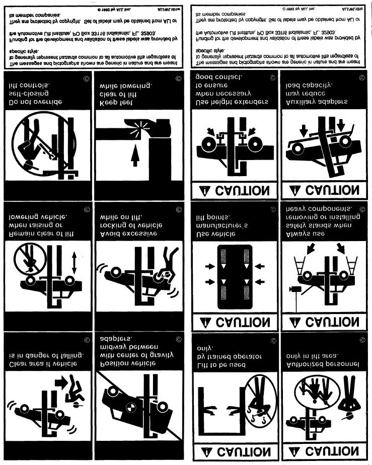
4 1. Carefully remove the crating and packing materials. CAUTION! Be careful when cutting steel banding material as items may become loose and fall causing personal harm or injury. 2. Inspect the lift for any signs of concealed shipment damage or shortages. Remember to INTRODUCTION report any shipping damage to the carrier and make a notation on the delivery receipt. 3. Check the voltage, phase and proper amperage requirements for the motor shown on the motor plate. Wiring should be performed by a certified electrician only. IMPORTANT SAFETY INSTRUCTIONS Read these safety instructions entirely! 1. Read and understand all safety warning procedures before operating lift. 2. Keep hands and feet clear. Remove hands and feet from any moving parts. Keep feet clear of lift when lowering. Avoid pinch points. 3. Keep work area clean. Cluttered work areas invite injuries. 4. Consider work area environment. Do not expose equipment to rain. Do not use in damp or wet locations. Keep area well lighted. 5. Only trained operators should operate this lift. All non-trained personnel should be kept away from work area. Never let non-trained personnel come in contact with, or operate lift. 6. Use lift correctly. Use lift in the proper manner. Never use lifting adapters other than what is approved by the manufacturer. 7. Do not override self-closing lift controls. 8. Remain clear of lift when raising or lowering vehicle. 9. Clear area if vehicle is on danger of falling. 10. Always insure that the safeties are engaged before any attempt is made to work on or near vehicle. 11. Dress properly. Non-skid steel -toe footwear is recommended when operating lift. 12. Guard against electric shock. This lift must be grounded while in use to protect the operator from electric shock. Never connect the green power cord wire to a live terminal. This is for ground only. 13. Danger! The power unit used on this lift contains high voltage. Disconnect power at the receptacle before performing any electrical repairs. Secure plug so that it cannot be accidentally plugged in during service. 14. Warning! Risk of explosion. This equipment has internal arcing or sparking parts which should not be exposed to flammable vapors. This machine should not be located in a recessed area or below floor level. 15. Maintain with care. Keep lift clean for better and safe performance. Follow manual for proper lubrication and maintenance instructions. Keep control handles and/or buttons dry, clean and free from grease and oil. 16. Stay alert. Watch what you are doing. Use common sense. Be aware. 17. Check for damaged parts. Check for alignment of moving parts, breakage of parts or any condition that may affect its operation. Do not use lift if any component is broken or damaged. 18. Never remove safety related components from the lift. Do not use lift if safety related components are damaged or missing. THIS SYMBOL POINTS OUT IMPORTANT SAFETY INSTRUCTIONS WHICH IF NOT FOL- LOWED COULD ENDANGER THE PERSONAL SAFETY AND/OR PROPERTY OF YOUR- SELF AND OTHERS AND CAN CAUSE PERSONAL INJURY OR DEATH. READ AND FOLLOW ALL INSTRUCTIONS IN THIS MANUAL BEFORE ATTEMPTING TO OPERATE THIS MACHINE.
5 TOOLS REQUIRED Rotary Hammer Drill Or Similar 3/4" Masonry Bit Hammer 4 Foot Level Open-End Wrench Set: 7/16" - 1-1/8" Socket And Ratchet Set: 7/16" - 1-1/8" Hex-Key / Allen Wrench Set Medium Crescent Wrench Medium Pipe Wrench Crow Bar For Shim Installation Chalk Line Medium Flat Screwdriver Tape Measure: 25 Foot Minimum Needle Nose Pliers IMPORTANT NOTICE These instructions must be followed to insure proper installation and operation of your lift. Failure to comply with these instructions can result in serious bodily harm and void product warranty. Manufacturer will assume no liability for loss or damage of any kind, expressed or implied resulting from improper installation or use of this product. PLEASE READ ENTIRE MANUAL PRIOR TO INSTALLATION. STEP ONE ( Selecting Site ) Before installing your new lift, check the following. 1. LIFT LOCATION: Always use architects plans when available. Check layout dimension against floorplan requirements making sure that adequate space is available. 2. OVERHEAD OBSTRUCTIONS: The area where the lift will be located should be free of overhead obstructions such as heaters, building supports, electrical lines etc. 3. DEFECTIVE CONCRETE: Visually inspect the site where the lift is to be installed and check for cracked or defective concrete. STEP TWO ( Floor Requirements ) Specifications of concrete must be adhered to. Failure to do so could cause lift failure resulting in personal injury or death. A level floor is suggested for proper installation. Small differences in floor slopes may be compensated for by proper shimming. If a floor is of questionable slope, consider a survey of the site and/or the possibility of pouring a new level concrete slab. DO NOT install this lift on any asphalt surface or any surface other than concrete. DO NOT install this lift on expansion seams or on cracked or defective concrete. DO NOT install this lift on a second / elevated floor without first consulting building architect. DO NOT install this lift outdoors unless special consideration has been made to protect the power unit from inclimate weather conditions. LIFT MODEL CONCRETE SPECIFICATIONS CONCRETE REQUIREMENT 12,000 Lb. Models 6 Min. Thickness / 2500 PSI 15,000 Lb. Models 7 Min. Thickness / 2500 PSI NOTE All models MUST be installed on 3000 PSI concrete only conforming to the minimum requirements shown above. New concrete must be adequately cured by at least 28 days minimum.
6 FLOORPLAN LAYOUT LAYOUT DIMENSIONS MODEL A B PR-12F 155 / 3835mm 28 / 711mm PR-12C 155 / 3835mm 28 / 711mm PR-15C 155 / 3835mm 28 / 711mm STEP THREE ( Site Layout ) 1. Determine which side will be the approach side. 2. Now determine which side you prefer the power unit to be located on. The POWERSIDE column has the power-unit mounting bracket attached to the side. ( See diagram above for power unit location. ) 3. Once a location is determined, use a carpenters chalk line to layout a grid for the post locations. Keep all dimensions and squareness within 1/8 or malfunctioning of the lift will occur. 4. After the post locations are properly marked, use a chalk or crayon to make an outline of the posts on the floor at each location using the post baseplates as a template. 5. Double check all dimensions and make sure that the layout is perfectly square. 6. Before continuing with the installation it is helpful to stand the posts up at their respective locations and get a visual of the shop, aisles and other clearances. Also, this is a good time to drive a vehicle into position and check for adequate clearance.

7 STEP FOUR ( Installing The POWERSIDE Column ) Fig Before proceeding, double check measurements and make certain that the bases of each column are square and aligned with the chalk line. 2. Using the baseplate on the POWERSIDE column as a guide, drill each anchor hole in the concrete approximately 7-1/2 deep using a rotary hammer drill and 3/4 concrete drill-bit. To assure full holding power, do not ream the hole or allow the drill to wobble. ( See Fig. 1 ) Fig After drilling, remove dust thoroughly from each hole using compressed air and/or wire brush. Make certain that the column remains aligned with the chalk line during this process. 8. With the shims and anchor bolts in place, tighten by securing the nut to the base then turning 2-3 full turns clockwise. DO NOT use an impact wrench for this procedure. ( See Fig. 4 ) Fig Assemble the washers and nuts on the anchors then tap into each hole with a hammer until the washer rests against the baseplate. Be sure that if shimming is required that enough threads are left exposed. ( See Fig. 2 ) Fig. 2 STEP FIVE ( Mounting The OFFSIDE column. ) 1. Position the OFFSIDE column at the designated chalk locations and secure to the floor following the same procedures as outlined in STEP FIVE. 7. If shimming is required, insert the shims as necessary under the baseplate so that when the anchor bolts are tightened, the columns will be plumb. ( See Fig. 3 ) NOTE: To ease installation of the top beam on CLEARFLOOR models, it helps to keep the anchor bolts loose on one of the columns until the top beam is mounted.
8 STEP SIX ( Mounting the OVERHEAD BEAM. ) Clearfloor Models Only 1. Using a lifting devise, raise the OVERHEAD beam in position on top of the columns. Bolt to the columns using the 3/8 x 1 Hex Bolts, Nuts and Washers. ( See Fig. 5 ) Fig. 5 STEP EIGHT ( Mounting The POWER UNIT ) 1. Attach the power unit to the POWERSIDE COLUMN using four 5/16" hex bolts and nylock nuts supplied. Fill the reservoir with 10 WT. HYDRAULIC OIL OR DEXRON TYPE III ATF. Make sure the funnel used to fill the power unit is clean. ( See Fig. 7 ) Fig 7 STEP SEVEN ( Mounting the TOP PULLEY ASSEMBLY. ) Floorplate Models Only 1. Using a lifting devise, raise the OVERHEAD beam in position on top of the columns. Bolt to the columns using the 3/8 x 1 Hex Bolts, Nuts and Washers. ( See Fig. 6 ) Fig. 6 STEP NINE ( Routing The EQUALIZER CABLES ) 1. Raise and lock each carriage approximately 28 above the ground. ( See Fig. 8 ) Fig 8 2. Make sure that the safety locks on each column are fully engaged before attempting to route equalizer cables. Carriages must be equal height from the floor before proceeding.
9 3. With the carriages in equal position from the floor, route the equalizer cables as shown below. ( See Fig. 9 & 10 ) Fig. 9 STEP TEN ( Installing The Hydraulic Lines. ) 1. Install the hydraulic lines as shown below paying careful attention to keep the hoses clean and free of debris. ( See Fig. 11 & 12 ) When routing the hydraulic hose through the columns, make sure to route through the retaining rings welded inside each column. Make sure that the hose is clear of any moving parts. It may be necessary to tie hose clear by using nylon tie straps or wire. Failure to keep hydraulic lines clear may result in hydraulic line failure which may result in damage or personal harm. Fig. 11 Fig After the equalizer cables have been routed. adjust each cable so that they are equal tension. IMPORTANT NOTE: The equalizer cables should be checked weekly for equal tension. Failure to do this will cause uneven lifting. The cables should always be adjusted so that they are equal tension when resting on the safety locks. IMPORTANT NOTE: When installing hydraulic fittings and hoses it is not necessary to use Teflon tape or other sealant. Teflon tape and other sealing compounds can contaminate the system and cause malfunctioning of lift.
10 Fig 12 STEP TWELVE ( Power Unit Installation. ) 1. The standard power unit for your lift is 220 volt, 60HZ, single phase. All wiring must be performed by a certified electrician only. SEE WIRING INSTRUCTIONS AFFIXED TO MOTOR FOR PROPER WIRING INSTRUCTIONS STEP ELEVEN ( Installing Overhead Micro Switch. ) 1. Install the overhead Micro Switch as shown below. Be sure to keep wire clear of moving parts. WIRING MUST BE PERFORMED BY A CERTIFIED ELECTRICIAN. ( See Fig. 13 ) Fig. 13 IMPORTANT INSTALLATION NOTES DO NOT run power unit with no oil. Damage to pump can occur. The power unit must be kept dry. Damage to power unit caused by water or other liquids such as detergents, acid etc., is not covered under warranty. Improper electrical hook-up can damage motor and will not be covered under warranty Motor can not run on 50HZ without a physical change in motor. Use a separate breaker for each power unit. Protect each circuit with time delay fuse or circuit breaker. For volt, single phase, use a 25 amp fuse. For volt, three phase, use a 20 amp fuse. For volt, three phase, use a 15 amp fuse. RISK OF EXPLOSION!! This equipment has internal arcing or sparking parts which should not be exposed to flammable vapors. Motor should not be located in a recessed area or below floor level.
11 STEP THIRTEEN ( Installation Of Swing Arms. ) 1. Install swing arms as described below. Grease the carriage tube and all pivot pins prior to installation.
12

13
14
Models: SURFACE MOUNTED FOUR-POST LIFTS INSTALLATION AND OPERATION MANUAL
 Forward this manual to all operators. Failure to operate this equipment as directed may cause injury. INSTALLATION AND OPERATION MANUAL SURFACE MOUNTED FOUR-POST LIFTS Models: FL-18 BP-18 BP-27/ BP-27A
Model PL-7 / PL-7X AUTOMOBILE STACKER INSTALLATION AND OPERATION MANUAL
 Forward this manual to all operators. Failure to operate this equipment as directed may cause injury. AUTOMOBILE STACKER INSTALLATION AND OPERATION MANUAL Model PL-7 / PL-7X Keep this operation manual
GLO-8000 SERIES (GLO-8000 & GLO-8000XLT)
") GLO-8000 SERIES (GLO-8000 & GLO-8000XLT) 8,000 LBS. CAPACITY FOUR-POST STORAGE LIFT INSTALLATION & OPERATION MANUAL SERIAL NUMBER: INSTALLATION DATE: EAGLE EQUIPMENT 1-800-336-2776 REV2011 03.0 BD SHIPPING
GLO-8000 SERIES (GLO-8000 & GLO-8000XLT) 8,000 LBS. CAPACITY FOUR-POST STORAGE LIFT INSTALLATION & OPERATION MANUAL SERIAL NUMBER: INSTALLATION DATE: EAGLE EQUIPMENT 1-800-336-2776 REV2011 03.0 BD SHIPPING
GLO-7000 SERIES (GLO-7000 & GLO-7000XLT)
") GLO-7000 SERIES (GLO-7000 & GLO-7000XLT) 7,000 LBS. CAPACITY FOUR-POST STORAGE LIFT (BLUE) INSTALLATION & OPERATION MANUAL SERIAL NUMBER: INSTALLATION DATE: EAGLE EQUIPMENT 1-800-336-2776 (STANDARD) SHIPPING
GLO-7000 SERIES (GLO-7000 & GLO-7000XLT) 7,000 LBS. CAPACITY FOUR-POST STORAGE LIFT (BLUE) INSTALLATION & OPERATION MANUAL SERIAL NUMBER: INSTALLATION DATE: EAGLE EQUIPMENT 1-800-336-2776 (STANDARD) SHIPPING
ATTENTION. 1. Do not attempt to use the power unit to extend your cylinder. This must be done manually.
 NSS8XLT Installation Manual ATTENTION By following the instructions in this manual you can save yourself much time, frustration and money. The installation of your lift will take 4-5 hours. Do not rush.
Read this entire manual before operation begins.
 Read this entire manual before operation begins. Record below the following information which is located on the serial number data plate. Serial No. Model No. Date of Installation Contents Specifications.............
INSTALLATION AND OPERATION MANUAL
 PLEASE READ THE ENTIRE CONTENTS OF THIS MANUAL PRIOR TO INSTALLATION AND OPERATION. BY PROCEEDING YOU AGREE THAT YOU FULLY UNDERSTAND AND COMPREHEND THE FULL CONTENTS OF THIS MANUAL. FORWARD THIS MANUAL
INSTALLATION AND OPERATION MANUAL
 PLEASE READ THE ENTIRE CONTENTS OF THIS MANUAL PRIOR TO INSTALLATION AND OPERATION. BY PROCEEDING YOU AGREE THAT YOU FULLY UNDERSTAND AND COMPREHEND THE FULL CONTENTS OF THIS MANUAL. FORWARD THIS MANUAL
Read this entire manual before operation begins.
 Read this entire manual before operation begins. Record below the following information which is located on the serial number data plate. Serial No. Model No. Date of Installation Contents Specifications.............
Read this entire manual before operation begins.
 Read this entire manual before operation begins. Record below the following information which is located on the serial number data plate. Serial No. Model No. Date of Installation Contents Specifications.............
Read this entire manual before operation begins.
 Read this entire manual before operation begins. Record below the following information which is located on the serial number data plate. Serial No. Model No. Date of Installation Contents Specifications.............
Atlas PV-9WP Addendum
 Atlas PV-9WP Addendum 9,000 lb. Capacity Two-Post Overhead Lift The Atlas PV-9WP above ground hoist is 6 inches wider than the Atlas PV-9P, giving it an overall width of 141 (11 9 ) and a drive thru width
Read this entire manual before operation begins.
 Rev. 12/12/2017 Read this entire manual before operation begins. Record below the following information which is located on the serial number data plate. Serial No. Model No. Date of Installation Contents
FP-12L 12,000 LBS. CAPACITY FOUR-POST LIFT INSTALLATION & OPERATION MANUAL READ THIS MANUAL BEFORE INSTALLING OR OPERATING YOUR LIFT
 FP-12L 12,000 LBS. CAPACITY FOUR-POST LIFT INSTALLATION & OPERATION MANUAL READ THIS MANUAL BEFORE INSTALLING OR OPERATING YOUR LIFT REV 20160208.SUN01 BD INSPECT YOUR LIFT UPON DELIVERY. NOTE ANY DAMAGE
INSTALLATION AND OPERATION MANUAL 9,000 POUND CAPACITY COMMERCIAL GRADE FOUR-POST LIFTS
 PLEASE READ THE ENTIRE CONTENTS OF THIS MANUAL PRIOR TO INSTALLATION AND OPERATION. BY PROCEEDING YOU AGREE THAT YOU FULLY UNDERSTAND AND COMPREHEND THE FULL CONTENTS OF THIS MANUAL. FORWARD THIS MANUAL
INSTALLATION AND OPERATION MANUAL 14,000 POUND CAPACITY COMMERCIAL GRADE FOUR-POST LIFTS
 INSTALLATION AND OPERATION MANUAL 14,000 POUND CAPACITY COMMERCIAL GRADE FOUR-POST LIFTS MODELS: HDS-14 HDS-14X PLEASE READ THE ENTIRE CONTENTS OF THIS MANUAL PRIOR TO INSTALLATION AND OPERATION. BY PROCEEDING
Model FP12K-K Flat Deck Four-Post Lift
 Model FP12K-K Flat Deck Four-Post Lift (12,000LBS Capacity) ASSEMBLY & OPERATION INSTRUCTION 2006.4. TABLE OF CONTENTS Important Note--------------------------------------------------------------------------------Page
INSTALLATION AND OPERATION MANUAL 1,500 POUND CAPACITY MOTORCYCLE / ATV LIFT Model: RML-1500XL
 PLEASE READ THE ENTIRE CONTENTS OF THIS MANUAL PRIOR TO INSTALLATION AND OPERATION. BY PROCEEDING YOU AGREE THAT YOU FULLY UNDERSTAND AND COMPREHEND THE FULL CONTENTS OF THIS MANUAL. FORWARD THIS MANUAL
Read this entire manual before operation begins.
 Read this entire manual before operation begins. Record below the following information which is located on the serial number data plate. Serial No. Model No. Date of Installation Contents Specifications.............
CONTENTS. Product Features and Specifications Installation Requirement Installation Exploded View Operation Instruction...
 1 CONTENTS Product Features and Specifications... 3 Installation Requirement... 5 Installation... 6 Exploded View... 20 Test... 22 Operation Instruction... 25 Maintenance... 26 Trouble Shooting... 27 Parts
Read this entire manual before operation begins.
 Read this entire manual before operation begins. Record below the following information which is located on the serial number data plate. Serial No. Model No. Date of Installation Contents Specifications.............
Forward this manual to all operators. Failure to operate this equipment as directed in this manual may cause injury.
 Forward this manual to all operators. Failure to operate this equipment as directed in this manual may cause injury. OPERATION MANUAL DTP607 DTP609 Lifting Capacity:3.2T/7000lbs Lifting Capacity:4.2T/9000lbs
CONTENTS. Product Features and Specifications...1. Installation Requirement Steps of Installation.. 5. Exploded View Test Run...
 CONTENTS Product Features and Specifications...1 Installation Requirement... 3 Steps of Installation.. 5 Exploded View...18 Test Run...21 Operation Instruction...22 Maintenance... 23 Trouble Shooting...
Model FP14KO-A Wheel alignment & Open Front Four-Post Lift
 Model FP14KO-A Wheel alignment & Open Front Four-Post Lift ( 14000LBS / 6300Kg Capacity) ASSEMBLY & OPERATION INSTRUCTIONS ( Series T1) 2009.7. INTRODUCTION Model FP14KO-A is a four-post lift is used in
CONTENTS. Product Features and Specifications Installation Requirement Steps of Installation 4. Exploded View Test Run...
 CONTENTS Product Features and Specifications... 1 Installation Requirement... 3 Steps of Installation 4 Exploded View... 14 Test Run... 16 Operation Instruction... 19 Maintenance... 20 Trouble Shooting...
MaxJax User Manual CAUTION
 MaxJax User Manual Revision F (4/12/14) PLEASE READ THE ENTIRE CONTENTS OF THIS MANUAL PRIOR TO INSTALLATION AND OPERATION. BY PROCEEDING, YOU AGREE THAT YOU FULLY UNDERSTAND AND COMPREHEND THE FULL CON-
ASSEMBLY & OPERATION INSTRUCTION MANUAL
 LR-26-PAD 6000 lb Capacity Low-Rise Pad Lift ASSEMBLY & OPERATION INSTRUCTION MANUAL 6,000 LB. LOW-RISE PAD LIFT Easy frame lifting on padded runways. Great for wheel and brake work, tire and wheel changing
INSTALLATION AND OPERATION MANUAL
 6,000 LB. CAPACITY / 2722 KG. Mid-RISE SCISSOR LIFT Models: MDS-6K MDS-6KF IMPORTANT SAFETY INSTRUCTIONS SAVE THESE INSTRUCTIONS Please read THE ENTIRE CONTENTS OF THIS MANUAL prior to installation AND
Read this entire manual before operation begins.
 Read this entire manual before operation begins. Record below the following information which is located on the serial number data plate. Serial No. Model No. Date of Installation Contents Specifications.............
Model FP14KA-C Alignment Four-Post Lift
 Model FP14KA-C Alignment Four-Post Lift (14000 LBS Capacity) ASSEMBLY & OPERATION INSTRUCTION 2006.4. TABLE OF CONTENTS Important Note--------------------------------------------------------------------------------Page
Model SL-12K-A SCISSOR LIFT. wheel alignment model. (11000 LBS / 5000Kg Capacity) INSTALLATION & OPERATION INSTRUCTION (SECOND EDITION)
 INSTALLATION & OPERATION INSTRUCTION (SECOND EDITION)") Model SL-12K-A SCISSOR LIFT wheel alignment model (11000 LBS / 5000Kg Capacity) INSTALLATION & OPERATION INSTRUCTION (SECOND EDITION) 2007. 6. CONTENTS Chapter 1 Introduction & Specifications ---------------------------------------
Model SL-12K-A SCISSOR LIFT wheel alignment model (11000 LBS / 5000Kg Capacity) INSTALLATION & OPERATION INSTRUCTION (SECOND EDITION) 2007. 6. CONTENTS Chapter 1 Introduction & Specifications ---------------------------------------
INSTALLATION & OPERATION MANUAL
 Two-Post Clear Floor Lift (Asymmetric) 9,000 lbs. Capacity (2,250 lbs. Max per Arm) INSTALLATION & OPERATION MANUAL IMPORTANT NOTES READ THE INSTALLATION AND OPERATION MANUAL IN ITS ENTIRETY BEFORE ATTEMPTING
CONTENTS. Product Features and Specifications...1. Installation Requirement...3. Steps of Installation...4. Exploded View Test Run...
 TP10AS 2-POST LIFT CONTENTS Product Features and Specifications...1 Installation Requirement...3 Steps of Installation...4 Exploded View...24 Test Run....28 Operation Instruction...29 Maintenance...30
Installation Instructions Capacity 10,000 lbs. (100 Series Lift)
") Installation Instructions Capacity 10,000 lbs. (100 Series Lift) IMPORTANT Reference ANSI/ALI ALIS, Safety Requirements for Installation and Service of Automotive Lifts before installing lift. OPERATING
Installation Instructions Capacity 10,000 lbs. (100 Series Lift) IMPORTANT Reference ANSI/ALI ALIS, Safety Requirements for Installation and Service of Automotive Lifts before installing lift. OPERATING
ATD-4P14CCA 14,000 lb Capacity Closed Front Alignment Lift ASSEMBLY & OPERATION INSTRUCTION MANUAL
 ATD-4P14CCA 14,000 lb Capacity Closed Front Alignment Lift ASSEMBLY & OPERATION INSTRUCTION MANUAL 14,000 LB. FOUR POST CABLE DRIVEN ALIGNMENT LIFT ATD-4P14CCA 14,000 lb. capacity Four post Cable driven
Air Curtain. Installation, Operating and Maintenance Instructions
 Installation, Operating and Maintenance Instructions Save this manual for future reference. Air Curtain Model Numbers: ES026, ES036, ES042, ES048, ES060, ES072 READ THIS OWNER S MANUAL CAREFULLY BEFORE
4QJY4.0-C & 4QJY4.0-C1 four post parking lift. Manual
 4QJY4.0-C & 4QJY4.0-C1 four post parking lift Manual Contents 1 Safety instruction and attentions.. 3 1.1 Cautions with words......3 1.2 Safety caution signal 4 1.3 Using Purpose.. 5 1.4 Expected Rated
CONTENTS. Product Features and Specifications...1. Installation Requirement Steps of Installation.. 5. Exploded View Test Run...
 CONTENTS Product Features and Specifications...1 Installation Requirement... 4 Steps of Installation.. 5 Exploded View...21 Test Run...26 Operation Instruction...27 Maintenance... 28 Trouble Shooting...
9,000 POUND TWO-COLUMN AUTOMOTIVE LIFT. Model: NW-2-9KACD MANUAL
 9,000 POUND TWO-COLUMN AUTOMOTIVE LIFT Model: NW-2-9KACD MANUAL 1 9,000 POUND CAPACITY MODEL: NW-2-9KACD TWO-COLUMN AUTOMOTIVE LIFT READ THIS ENTIRE MANUAL BEFORE OPERATION BEGINS RECORD BELOW THE FOLLOWING
MTP-15 15,000 LBS. CAPACITY TWO-POST OVERHEAD LIFT INSTALLATION & OPERATION MANUAL READ THIS MANUAL BEFORE INSTALLING OR OPERATING YOUR LIFT
 MTP-15 15,000 LBS. CAPACITY TWO-POST OVERHEAD LIFT INSTALLATION & OPERATION MANUAL READ THIS MANUAL BEFORE INSTALLING OR OPERATING YOUR LIFT REV 20150810.TIA03 BD INSPECT YOUR LIFT UPON DELIVERY. NOTE
TP15KC-KX Two-Post Clear Floor Lift
 TP15KC-KX Two-Post Clear Floor Lift (Symmetric) 15,000 lbs. Capacity (3,750 lbs. Max per Arm) ASSEMBLY & OPERATION INSTRUCTION MANUAL Feb. 2017 IMPORTANT NOTES READ THE INSTALLATION AND OPERATION MANUAL
QJY245DS~DA. Two Post Lift Installation & Adjustment Manual
 QJY245DS~DA Two Post Lift Installation & Adjustment Manual Table of Contents 1. Warning 2 2. Summary 2 3. Use 2 4. Mainly technology parameter 2 5. Basic structure of the production 3 6. Safety device
Lifting height 5.5" - 72" with adapters " Height overall 165" Width between columns 122" Drive through 109" Width overall 151.
 Model Number TP12KC-D Capacity 12,000 lbs. Lifting height 5.5" - 72" with adapters 79.625" Height overall 165" Width between columns 122" Drive through 109" Width overall 151.125" Arm extension 37.5" -
TWO POST LIFT. Operation Manual & Instruction STRONGMAN TOOLS LTD
 TWO POST LIFT USER S MANUAL Operation Manual & Instruction STRONGMAN TOOLS LTD 1 IMPORTANT SAFETY INSTRUCTIONS SAVE THESE INSTRUCTIONS PLEASE READ THE ENTIRE CONTENTS OF THIS MANUAL PRIOR TOINSTALLATION
ATD-2P9A 9,000 lbs. Two Post Clear Floor Lift Owner s Manual
 ATD-2P9A 9,000 lbs. Two Post Clear Floor Lift Owner s Manual Features: Specifications: IMPORTANT NOTES READ THE INSTALLATION AND OPERATION MANUAL IN ITS ENTIRETY BEFORE ATTEMPTING TO INSTALL THE LIFT.
Installation Instructions X-Force UTV Lift (000 Series) Capacity 2,275 lbs (1,035 kg)
 Capacity 2,275 lbs (1,035 kg)") Installation Instructions X-Force UTV Lift (000 Series) Capacity 2,275 lbs (1,035 kg) Read entire manual before assembling, installing, operating, or servicing this equipment. LP20640 IN20793 September
Installation Instructions X-Force UTV Lift (000 Series) Capacity 2,275 lbs (1,035 kg) Read entire manual before assembling, installing, operating, or servicing this equipment. LP20640 IN20793 September
equalizersystems.com. Installation and Operation Guide October Revision- November 2016
 1-800-846-9659 equalizersystems.com Installation and Operation Guide October 2010 Revision- November 2016 AJ Series Single Leg Hydraulic Jack: 7,500# Capacity Installation Tools Required for Installation
Electric Chainsaw Sharpener With Bar Mount
 Electric Chainsaw Sharpener With Bar Mount Owner s Manual WARNING: Read carefully and understand all ASSEMBLY AND OPERATION INSTRUCTIONS before operating. Failure to follow the safety rules and other basic
60 Watt Industrial LED Low Bay Light
 60 Watt Industrial LED Low Bay Light Owner s Manual WARNING: Read carefully and understand all ASSEMBLY AND OPERATION INSTRUCTIONS before operating. Failure to follow the safety rules and other basic safety
INSTALLATION GUIDE. Universal System for Zero Turn Mowers
 INSTALLATION GUIDE Universal System for Zero Turn Mowers Table of Contents General Information 1 Important Notice to Purchaser 2 Specifications 2 Intended Usage 2 Important Information 3 General Safety
Installation and Operation Manual
 1645 Lemonwood Dr. Santa Paula, CA 93060 USA Toll Free: (800) 253-2363 Telephone: (805) 933-9970 bendpak.com GrandPrix Two-Post Lifts Installation and Operation Manual Manual Revision C2 August 2018 Manual
Air-Operated Waste Oil Drainer
 Air-Operated Waste Oil Drainer 20-Gallon Tank Owner s Manual WARNING: Read carefully and understand all ASSEMBLY AND OPERATION INSTRUCTIONS before operating. Failure to follow the safety rules and other
Installation and Operation Guide October 2010
 1-800-846-9659 www.equalizersystems.com Hydraulic Trailer Jack Installation and Operation Guide October 2010 Hydraulic Trailer Jack AJ Dual Leg General Description Dual leg trailer jack Lifting capacity:
SHIPPING DAMAGE CLAIMS
 INSTRUCTION MANUAL ADMIRAL 9000 SERIES Revision B 3-2011 pn# 199822 PLEASE READ THE ENTIRE CONTENTS OF THIS MANUAL PRIOR TO INSTALLATION AND OPERATION. BY PROCEEDING, YOU AGREE THAT YOU FULLY UNDERSTAND
150-Lb. Drywall and Panel Hoist
 150-Lb. Drywall and Panel Hoist Owner s Manual WARNING: Read carefully and understand all ASSEMBLY AND OPERATION INSTRUCTIONS before operating. Failure to follow the safety rules and other basic safety
USE AND MAINTENANCE MANUAL
 USE AND MAINTENANCE MANUAL TWO POST VEHICLE LIFT 2 IMPORTANT SAFETY INSTRUCTIONS SAVE THESE INSTRUCTIONS WARNING! PLEASE READ THE ENTIRE CONTENTS OF THIS MANUAL PRIOR TOINSTALLA- TION AND OPERATION. BY
Read this entire manual before operation begins.
 Revised 9/5/2018 Read this entire manual before operation begins. Record below the following information which is located on the serial number data plate. Serial No. Model No. Date of Installation Contents
INSTALLATION AND OPERATION MANUAL
 TRANSMISSION JACKS MODELS: RTJ-1 RTJ-660 RTJ-1100 RTJ-3000 PLEASE READ THE ENTIRE CONTENTS OF THIS MANUAL PRIOR TO INSTALLATION AND OPERATION. BY PROCEEDING YOU AGREE THAT YOU FULLY UNDERSTAND AND COMPREHEND
User s Manual and Operating Instructions
 User s Manual and Operating Instructions Model Numbers: CL-36-BDF-A, CL-42-BDF-A, CL-48-BDF-A E355088 READ AND SAVE THESE INSTRUCTIONS IMPORTANT: Read and understand all of the instructions in this manual
OBE, OBEXU, ON BOARD Battery Chargers
 C O R P O R A T IO N O P E R A T I N G I N S T R U C T I O N S OBE, OBEXU, ON BOARD Battery Chargers INTRODUCTION: These chargers are designed for the permanent installation on battery powered vehicles
DISC BRAKE CALIPER TOOL SET
 DISC BRAKE CALIPER TOOL SET 40732 ASSEMBLY AND OPERATING INSTRUCTIONS Diagrams within this manual may not be drawn proportionally. Due to continuing improvements, actual product may differ slightly from
OBAE, OBAEXU, ON BOARD Battery Chargers
 C O R P O R A T IO N O P E R A T I N G I N S T R U C T I O N S OBAE, OBAEXU, ON BOARD Battery Chargers INTRODUCTION: The OBAE line of chargers are designed for the permanent installation on battery powered
Large Hydraulic Bead Breaker
 Large Hydraulic Bead Breaker Owner s Manual WARNING: Read carefully and understand all ASSEMBLY AND OPERATION INSTRUCTIONS before operating. Failure to follow the safety rules and other basic safety precautions
1000-LB. MOTORCYCLE LIFT TABLE OWNER S MANUAL
 1000-LB. MOTORCYCLE LIFT TABLE OWNER S MANUAL WARNING: Read carefully and understand all ASSEMBLY AND OPERATION INSTRUCTIONS before operating. Failure to follow the safety rules and other basic safety
50 Ft. Retractable Cord Reel
 50 Ft. Retractable Cord Reel with Triple Tap Owner s Manual WARNING: Read carefully and understand all ASSEMBLY AND OPERATION INSTRUCTIONS before operating. Failure to follow the safety rules and other
INSTALLATION AND OPERATION MANUAL Low Profile Long Frame Floor Jack Model: RFJ-3000LPF REV B
 PLEASE READ THE ENTIRE CONTENTS OF THIS MANUAL PRIOR TO INSTALLATION AND OPERATION. BY PROCEEDING YOU AGREE THAT YOU FULLY UNDERSTAND AND COMPREHEND THE FULL CONTENTS OF THIS MANUAL. FORWARD THIS MANUAL
before serial number 2214
 before serial number 2214 Contents Page Safety Rules... 3 Pre-operational & Safety Inspection... 4 Operating Instructions... 6 Transport... 12 Maintenance & Routine Service... 12 Specifications... 14 SAFETY
Manifold w/ Needle Valve Instruction Manual
 MODELS: MFC2 & MFC4 Manifold w/ Needle Valve Instruction Manual SFA Companies 10939 N. Pomona Ave. Kansas City, MO 64153 Tel: 888-332-6419 - Fax: 816-448-2142 E-mail: sales@bvahydraulics.com Website: www.bvahydraulics.com
ATD2P11BS. Two-Post Clear Floor Bi-Symmetric Automotive Lift. Installation & Operation Manual. 11,000 lbs. Capacity. (2,750 lbs.
 Two-Post Clear Floor Bi-Symmetric Automotive Lift 11,000 lbs. Capacity (2,750 lbs. Max per Arm) Installation & Operation Manual 1. Safety Information 1.1 Note, Caution and Warning 1.2 Important Information
Manual Tire Changing Station
 Manual Tire Changing Station Owner s Manual WARNING: Read carefully and understand all ASSEMBLY AND OPERATION INSTRUCTIONS before operating. Failure to follow the safety rules and other basic safety precautions
Garden Hose Reel with 3/4In. x 100Ft. Hose. Owner s Manual
 Garden Hose Reel with 3/4In. x 100Ft. Hose Owner s Manual WARNING: Read carefully and understand all ASSEMBLY AND OPERATION INSTRUCTIONS before operating. Failure to follow the safety rules and other basic
Installation Instructions Capacity 10,000 lbs. DP10 (200 Series Lift)
") Installation Instructions Capacity 10,000 lbs. DP10 (200 Series Lift) IMPORTANT Reference ANSI/ALI ALIS, Safety Requirements for Installation and Service of Automotive Lifts before installing lift. OPERATING
Installation Instructions Capacity 10,000 lbs. DP10 (200 Series Lift) IMPORTANT Reference ANSI/ALI ALIS, Safety Requirements for Installation and Service of Automotive Lifts before installing lift. OPERATING
SUBMERSIBLE MINI-PUMP
 SUBMERSIBLE MINI-PUMP Model 41287 Set up And Operating Instructions Diagrams within this manual may not be drawn proportionally. Due to continuing improvements, actual product may differ slightly from
Kitchen Tech Series Air Curtain
 Installation, Operating, and Maintenance Instructions Save this manual for future reference. Kitchen Tech Series Air Curtain Model Numbers: KTECH026, KTECH036, KTECH042, KTECH048, KTECH060, KTECH072, KTECH084,
Single Leg AM / CM 20, 24 and 30. Installation
 1-800-846-9659 www.equalizersystems.com Installation and Operation Guide January 2011 Single Leg AM / CM 20, 24 and 30 Installation Tools Required for Installation Ratchet, Sockets and Wrench Set Wire
RollSeal 1733 County Road 68 Bremen, Alabama Part No Rev Owner s Manual RS-Divider Curtain
 1. 2. 7 3. 4. RollSeal 1733 County Road 68 Bremen, Alabama 35033 256-287-7000 Part No 4801-5176 Rev 12-11-17 Owner s Manual RS-Divider Curtain Table of Contents 1 Warnings (Avertissements)... 3 2 Limited
SUBMERSIBLE SUMP PUMPS
 SUBMERSIBLE SUMP PUMPS Zoeller is a registered trademark of Zoeller Co. All Rights Reserved. MODELS #1073-0001, 1075-0001 Español p. 9 ATTACH YOUR RECEIPT HERE Serial Number Purchase Date Questions, problems,
OPERATION AND ASSEMBLY MANUAL HIGH JACK STANDS Models: RJS-1T RJS-1TF RJS-2TH
 PLEASE READ THE ENTIRE CONTENTS OF THIS MANUAL PRIOR TO INSTALLATION AND OPERATION. BY PROCEEDING YOU AGREE THAT YOU FULLY UNDERSTAND AND COMPREHEND THE FULL CONTENTS OF THIS MANUAL. FORWARD THIS MANUAL
Hydraulic Bead Breaker Kit
 Hydraulic Bead Breaker Kit Owner s Manual WARNING: Read carefully and understand all ASSEMBLY AND OPERATION INSTRUCTIONS before operating. Failure to follow the safety rules and other basic safety precautions
QPET, QPETXU Battery Chargers
 C O R P O R A T IO N O P E R A T I N G I N S T R U C T I O N S QPET, QPETXU Battery Chargers INTRODUCTION: The QPET line of chargers are designed for general purpose deep cycle batteries. They are an electronically
24 VOLT AUTOMATIC BATTERY CHARGER PART NO
 24 VOLT AUTOMATIC BATTERY CHARGER PART NO. 957732 AC Input: DC Output: Battery Type: Specifications 230 volts, 50 hertz, 3.5 amps, single-phase 24 volts, 20 amps initially tapering to 6 amps 24 volt, 12
Adjustable Steel Welding Table
 Adjustable Steel Welding Table Owner s Manual WARNING: Read carefully and understand all ASSEMBLY AND OPERATION INSTRUCTIONS before operating. Failure to follow the safety rules and other basic safety
INSTALLATION AND OPERATION MANUAL
 Tire Vulcanizer Model: RV80L VER A PLEASE READ THE ENTIRE CONTENTS OF THIS MANUAL PRIOR TO INSTALLATION AND OPERATION. BY PROCEEDING YOU AGREE THAT YOU FULLY UNDERSTAND AND COMPREHEND THE FULL CONTENTS
This Manual Provides Installation and Operation Instructions for the following models:
 OWNER'S MANUAL Capstan Powered Lift Assist This Manual Provides Installation and Operation Instructions for the following models: CAPSTAN 1000 CAPSTAN 300 QUICK CATCH POT PULLER pwcs101 12 Volt Powered
TWO POST LIFT INSTALLATION AND OWNERS MANUAL
 TWO POST LIFT INSTALLATION AND OWNERS MANUAL DP15, DP15-2 Capacity 15,000 lbs. 1. TABLE OF CONTENTS 2. Important Information.. 2 3. Section 1 Owner s Manual Safety Instructions... 3 Monthly Maintenance...
INSTALLATION MANUAL & OPERATION INSTRUCTIONS. OVERHEAD CAR LIFT 2-POST LIFT AUTO HOIST APlusLift HW-10KOH
 INSTALLATION MANUAL & OPERATION INSTRUCTIONS OVERHEAD CAR LIFT 2-POST LIFT AUTO HOIST APlusLift HW-10KOH 1 READ THIS MANUAL COMPLETELY BEFORE INSTALLING LIFT!!! DISTRIBUTED BY: Songa Enterprises LLC 8512
INSTALLATION, OPERATION & MAINTENANCE MANUAL
 INSTALLATION, OPERATION & MAINTENANCE MANUAL Two Post Surface Mounted Lift MODEL X10 10,000 LBS. CAPACITY 2500 LBS. PER ARM 200 Cabel Street, P.O. Box 3944 Louisville, Kentucky 40201-3944 Email:sales@challengerlifts.com
IMPORTANT READ ME FIRST
 IMPORTANT READ ME FIRST Thank you for purchasing your Kushlan Mixer. We hope that you will enjoy using it for many years to come. SHOULD YOU REQUIRE ANY SET-UP OR OPERATING ASSISTANCE WITH YOUR PRODUCT,
Installation and Service Manual
 RESIDENTIAL PLATFORM LIFTS RPL400 / RPL600 Installation and Service Manual WARNING! STRICT ADHERENCE TO THESE INSTALLATION INSTRUCTIONS IS REQUIRED to promote the safety of those installing this product,
HF4145 FOLDING MULTI-POSITION WORKOUT BENCH
 HF4145 FOLDING MULTI-POSITION WORKOUT BENCH Note: Both Serial Number and Model Number are Required when Ordering Parts RECORD SERIAL NUMBER HERE CATALOG NUMBER 0406-001 Customer Service (800) 548-5438
Index. 1. Important safety instructions Overview of the lift Installation instructions Operation instructions 8-9
 2 Index 1. Important safety instructions 4-5 1.1 Safety Warnings 1.2 Qualified personnel 1.3 Safety 1.4 Warning signs 2. Overview of the lift 6 2.1 General descriptions 2.2 Technical data 2.3 Construction
OWNER S MANUAL SELF-PRIMING PORTABLE UTILITY PUMP
 Model 54011-0 OWNER S MANUAL SELF-PRIMING PORTABLE UTILITY PUMP Questions, problems, missing parts? Before returning to the store call AQUAPRO Customer Service 8 a.m. - 5 p.m., EST, Monday-Friday 1-844-242-2475
FLEX MOUNT KIT INSTALLATION INSTRUCTIONS FMK-SW (Swing Gates) & FMK-SL (Sliding Gates)
 & FMK-SL (Sliding Gates)") Securitron Magnalock Corp. Tel 775.355.5625 550 Vista Boulevard Fax 775.355.5633 Sparks, NV 89434 info@securitron.com www.securitron.com ASSA ABLOY, the global leader in door opening solutions FLEX MOUNT
Securitron Magnalock Corp. Tel 775.355.5625 550 Vista Boulevard Fax 775.355.5633 Sparks, NV 89434 info@securitron.com www.securitron.com ASSA ABLOY, the global leader in door opening solutions FLEX MOUNT
1300 lb Capacity Trike Lift
 M-1300C-TRIKE 1300 lb Capacity Trike Lift USER S MANUAL TRIKE MOTORCYCLE LIFT An extra wide platform designed especially for three-wheel motorcycles. M-1300-TRIKE Trike Motorcycle Lift SPECIFICATIONS:
1000-lb Hydraulic Truck Crane
 1000-lb Hydraulic Truck Crane Owner s Manual WARNING: Read carefully and understand all ASSEMBLY AND OPERATION INSTRUCTIONS before operating. Failure to follow the safety rules and other basic safety precautions
TJ Series- 8065M. Hydraulic Trailer Tongue Jack System. Installation. Installation and Operation Guide January 2012 Revision- April 2013
 1-800-846-9659 equalizersystems.com Installation and Operation Guide January 2012 Revision- April 2013 TJ Series- 8065M Hydraulic Trailer Tongue Jack System Tools Required for Installation Installation
KENCOVE PD100 MANUAL TILT POST DRIVER
 OPERATOR S MANUAL KENCOVE PD100 MANUAL TILT POST DRIVER WWW.KENCOVE.COM 800-536-2683 344 KENDALL RD, BLAIRSVILLE, PA 15717 Table of Contents Specifications/Requirements 1 Introduction 2 Equipment Inspection
PUSH BUTTON KEY CABINET
 PUSH BUTTON KEY CABINET Model 95689 INSTALLATION And Operation Instructions Due to continuing improvements, actual product may differ slightly from the product described herein. 3491 Mission Oaks Blvd.,
SUBMERSIBLE SUMP PUMPS
 SUBMERSIBLE SUMP PUMPS Zoeller is a registered trademark of Zoeller Co. All Rights Reserved. MODEL #1099-0001 Español p. 11 ATTACH YOUR RECEIPT HERE Serial Number Purchase Date Questions, problems, missing
20 Gauge Super-Speed. shoprpmachine
 Operator tor s s manual 20 Gauge Super-Speed 1 WARRANTY Our guarantee on the products we manufacture is limited to repair or replacement without charge, of any part found to be defective in materials or