IMPORTANT INFORMATION
|
|
|
- Alexina Nash
- 5 years ago
- Views:
Transcription


1
2 TABLE OF CONTENTS IMPORTANT INFORMATION... 2 LIFT AREA LAYOUT INFORMATION... 3 TOOLS and EQUIPMENT REQUIRED FOR INSTALL... 4 INSTALLATION PROCEDURE... 5 FOUNDATION and ANCHORING REQUIREMENTS... 6 DEFINITION of LIFT CONTROLS OWNER / EMPLOYER RESPONSIBILITIES SAFETY PROCEDURES AND OPERATING INSTRUCTIONS LIFT LOCKOUT/TAGOUT PROCEDURE PREVENTIVE MAINTENANCE SCHEDULE TROUBLESHOOTING ILLUSTRATED PARTS BREAKDOWN IMPORTANT INFORMATION Two Post Lifts 1. Any freight damage must be noted on the freight bill before signing and reported to the freight carrier with a freight claim established. Identify the components and check for shortages. If shortages are discovered, please contact the Distributor / Sales Representative in your area for service. 2. Consult building owner and / or architect s plans when applicable to establish the best lift location. The lift should be located on a relatively level floor with 4 in. minimum thickness, 3000-psi concrete slab that has been properly cured. 3. Make sure you have extra help or heavy duty lifting equipment when unloading and assembling the lift. 4. Please read the safety procedures and operating instructions in this manual before operating lift. Keep this manual near lift at all times. Make sure all operators read this manual. 5. The lift should be located on a relatively level floor of less than 3 degrees slope. If slope is questionable, consider a survey of the site and/or the possibility of pouring a new level concrete slab. 6. Make sure you have enough area and ceiling height to install lift. (See Lift Specifications) 7. Never raise a car until you have double checked all bolts, nuts and hose fittings. 8. Always lock the lift before going under the vehicle. Never allow anyone to go under the lift when raising or lowering. 2
3 LIFT AREA LAYOUT INFORMATION 11 0 (3353mm) Min. To Nearest Obstruction APPROACH 13 0 (3963mm) Min. To Nearest Obstruction 3
4 DIFFERENT INSTALLATION HEIGHT OPTIONS NOTE: This lift has two set-up height dimensions as noted below: (Check for ceiling clearance first to see how high the lift can be set up) 4
5 TOOLS & EQUIPMENT REQUIRED FOR INSTALL The installation of this lift is relatively simple and can be accomplished by two men in a few hours. The following tools and equipment are needed: Hoist or Forklift (optional) 4 Level Two 10 to 12 step ladders Vise grips ISO 32 Light Hydraulic Oil (approx. 12 quarts) 8mm Socket Head Wrench Rotary Hammer Drill with ¾ in. Drill Bit Sockets and Open Wrench set, ½ in. thru 1-1/2 in. (Core Drill Rebar Cutter recommended) (1-1/8 in. for ¾ in. Anchors) Torque wrench Teflon Tape Tape Measure INSTALLATION PROCEDURE STEP 1: After unloading the lift, place it near the intended installation location. STEP 2: Remove the shipping bands and packing materials from the lift. The power unit will be unpacked from the top. Note: Be careful not to drop power unit on heavy end STEP 3: Open the wrapping from the upper column and carefully remove the parts from inside. Unbolt the column from the shipping brackets. Unbolt the up-rights (Item #20 & #84) from the columns and assemble it to the columns. (Item #19 & #79) - (see Fig. #9) STEP 4: Slide each carriage 50-60" towards top of columns to expose base of cylinders. Open the oil port of each cylinder by unscrewing the black plastic cap. The oil port will face the backside of the column and the notch on the bottom of the cylinder will fit into the hole in the center of the base plate. STEP 5: Position the columns facing each other 103 inside base plates (see Fig. #1). Square the columns by measuring diagonally from corner points on base plates (within1/4 ). STEP 6: The existing holes in column base plate as a guide for drilling the 3/4 diameter holes into the concrete. Drill the anchor holes only for the main side column, installing anchors as you go. NOTE: Drilling thru concrete slab (recommended) will allow the anchor to be driven thru the bottom of slab, if the threads are damaged or if the lift will need to be relocated. (see Foundation and Anchoring Requirements and Anchoring Tip Instructions) 5
6 FOUNDATION AND ANCHORING REQUIREMENTS 1. Concrete shall have compression strength of at least 3,000 PSI and a minimum thickness of 4 in order to achieve a minimum anchor embedment of 3 ¼. NOTE: When using the standard supplied ¾ x 5 ½ long anchors; if the top of the anchor exceeds 2 ¼ above the floor grade, you DO NOT have enough embedment. 2. Maintain a 6 minimum distance from any slab edge or seam. Hole to hole spacing should be a minimum 6 ½ in any direction. Hole depth should be a minimum of 4. CAUTION 3. DO NOT install on asphalt or other similar unstable surface. Columns are supported only by anchoring to floor. 4. Using the horseshoe shims provided, shim each column base as required until each column is plumb. If one column has to be elevated to match the plane of the other column, full size base shim plates should be used. Torque anchors to 85 ft-lbs. Shim thickness MUST NOT exceed ½ when using the 5 ½ long anchors provided with the lift. Adjust the column extensions plumb. 5. If anchors do not tighten to 85 ft-lbs. installation torque, replace the concrete under each column base with a 4 x 4 x 6 thick 3,000 PSI minimum concrete pad keyed under and flush with the top of existing floor. Allow concrete to cure before installing lifts and anchors (typically 2 to 3 weeks). 6
7 ANCHORING TIP INSTRUCTIONS CAUTION Anchors must be at least 6 from the edge of the slab or any seam. Use a concrete hammer drill with a carbide tip, solid drill bit the same diameter as the anchor, ¾. (.775 to.787 inches diameter). Do not use excessively worn bits or bits which have been incorrectly sharpened. Keep the drill in a perpendicular line while drilling. Let the drill do the work. Do not apply excessive pressure. Lift the drill up and down occasionally to remove residue to reduce binding. Drill the hole to depth equal to the length of anchor. NOTE: Drilling thru concrete (recommended) will allow the anchor to be driven thru the bottom of foundation if the threads are damaged or if the lift will need to be relocated. For better holding power blow dust from the hole. Place a flat washer and hex nut over threaded end of anchor, leaving approximately 1/2 inch of thread exposed carefully tap anchor. Do not damage threads. Tap anchor into the concrete until nut and flat washer are against base plate. Do not use an impact wrench to tighten! Tighten the nut, two or three turns on average concrete (28-day cure). If the concrete is very hard only one or two turns may be required. Check each anchor bolt with torque wrench set to 85 foot pounds. 7
8 STEP 7: Using a level, check column for side-to-side plumb and front-to-back plumb. If needed, use horseshoe shims provided by placing shims underneath the base plate and around the anchor bolt. This will prevent bending the column bottom plates (Shim thickness should not exceed 2-1/4 ). Tighten 3/4 anchor bolts to 85 ft-lbs. of torque. STEP 8: Using a tape measure, measure from back corner of the base to the opposite back corner to insure legs are square. After confirming dimensions, drill and install the anchors on the slave side column. STEP 9: Level the second column as described in STEP 7. STEP 10: Install the overhead cross beam. This cross beam has two pieces, to be connected by six (6) bolts in the center of the beam. Be sure to bolt them together by installing the bolts from inside the cross beam out. This is to avoid interference with the cable when operating the lift. STEP 11: Connect the latch release cable (Item # 69) between the two latches as shown on (Fig. #4 & #5). Check the tension of the cable is tight. Pull the single point release handle several times and check the tension again by making sure both latches release at the same time when the handle is pulled. STEP 12: Mount the power unit on the main side leg to the power unit bracket using the four 5/16 bolts and nuts. Install the T fitting with o-ring on the power unit, and then install the 6 pipe into the backside of the main column cylinder (power unit side). Connect the 90-degree hydraulic fitting on the other end of the 6 pipe. NOTE: Use Teflon Tape on both ends of 6 Pipe and at connections of 90-degree fitting and Pipe connections. Connect the short hydraulic hose to one side of the T fitting at power unit, then run the hose down the column and connect to the head beam to the opposite column, then down the side and connect to the fitting on the other column cylinder. (see Fig #6) STEP 13: 1. Connect the equalizing cables (Item #6) as shown in the cable diagram below on (Fig. # 2). Do not tighten at this stage of assembly. 2. Remove the access panel on the front of the carriage. 3. Feed the equalizer cable down through carriage and around lower cable sheave. 4. Push the equalizer cable up through the bottom of the carriage. For Low Setting run the cable all the way up through the High Set ting Tie Off and out the top of the carriage. Note the High Setting Tie Off located inside the carriage. The cable must run through that tie off or it will not be long enough to reach. Place locknut on end of cable until 1/2" of threads are showing above locknut. 5. For High Setting run cable up through Tie Off and out access panel in front of carriage. Place locknut on end of cable until 1/2" of threads are showing above locknut. Pull back down through carriage until properly seated in High Setting Tie Off. 6. Wrap cable up and around Upper Cable Sheaves and down to Upper Carriage Tie Off. 7. Repeat for other cable. STEP 14: Adjust the carriage cable tension. This is accomplished by tightening the upper carriage tie off nut. The left post carriage nut adjusts the right column carriage, and the right column carriage nut adjusts the left column carriage. Adjust each cable to approximately 1/2 side-to-side play. Check both latch releases to insure the carriage is still engaged in the appropriate latch. 8
9 9
10 STEP 15: Install the half moon gear restraints on each swing arm (USA side up). NOTE: Do not tighten bolts completely at this time. Next, position the swing arms on the carriages using the included 1-1/2 diameter pins (2 short for front arms and 2 long for rear arms). Check for proper engagement of the arm restraints the rack should fully engage the gear on the arm. After checking that gear and rack fully mesh, tighten bolts on gear restraints. STEP 16: Install the Overhead Shut-Off Bar limit switch. Identify the #1 HOT WIRE from the power source and connect to the Carriage Limit Switch and the Overhead Shut Off Bar Limit Switch. After both of the limit switches have been connected (wire nut and tape properly) into the #1 HOT WIRE, connect the #1 HOT WIRE to the L2 connection inside the power unit electrical box. Identify the #2 HOT WIRE and connect it directly to the L3 connection inside of the power unit electrical box. Connect the GROUND WIRE to the ground screw inside of the power unit electrical box. 10
11 STEP 17: Remove the vent plug from the power unit and fill the reservoir. Use a Ten Weight (ISO AW32) non-foaming, non-detergent hydraulic fluid (i.e. Texaco HD32 or equal). The unit will hold approximately twelve quarts of fluid. STEP 18: Make the Electrical hookup to the power unit; 220V Single Phase. It is recommended that a 220 Volt, 30 Amp twist lock plug be installed in the power line just ahead of the power unit. Use wire capable of supporting a 30-amp circuit. Warning: the wiring must comply with local code. Have a certified electrician make the electrical hook-up to the power unit. Protect each circuit with time delay fuse or circuit breaker; 208v-230v single phase 60 Hz 30 amp. STEP 19: Do not place any vehicle on the lift at this time. Cycle the lift up and down several times to insure latches engage properly and all air is removed from the system. To lower the lift, first raised the lift to clear the latches and then pull down the safety release handle to lower the lift. If latches function out of sync, tighten the cable on the latch that engages first. STEP 20: Operate lift and apply pressure to cable to insure motor shuts off prior to any part of vehicle coming in contact with overhead crossbeam. Adjust cable if necessary and secure with crimp fitting. Remove any excess cable with wire cutters. (see Fig # 3) DEFINITION OF LIFT CONTROLS Item No. Type Purpose 1 Latch Release Handle Used to release safety latches when lowering vehicle. 2 Raise Switch Controls electrical power to the power unit. Push to turn-on, and push again to turn-off the power unit. 3 Lower lever Used to relieve hydraulic pressure when pressed down. 4 Power Unit Reservoir Cap Cap for the power unit fluid reservoir. ENSURE THAT ALL CABLE SHEAVES, BEARINGS, AND SHAFTS ARE SUFFICIENTLY LUBRICATED. ALSO, THE CORNERS OF EACH COLUMN SHOULD BE LIGHTLY GREASED WITH QUALITY TYPE LITHIUM GREASE PRIOR TO OPERATING THE LIFT. LUBRICATE ALL ON AN ANNUAL BASIS. Motors and all electrical components are not sealed against the weather and moisture. Install this lift in a protected indoor location. Failure by the owner to provide the recommended shelter could result in unsatisfactory lift performance, property damage, or personal injury. 11

12 SAFETY AND OPERATING INSTRUCTIONS ONLY AUTHORIZED PERSONNEL ARE TO OPERATE LIFT Read operating and safety procedures manual completely before operating lift. Properly maintain and inspect lift in accordance to owner s manual. Do not operate a lift that is damaged or in need of repair. Allow only authorized personnel in the lift bay. Stay clear of Lift when raising or lowering (NO RIDERS) Keep hands and feet away from pinch points at all times. Never override the Lifts operating and safety controls. If a vehicle is suspected of falling, clear area immediately. Do not rock vehicle while positioned on lift. Always use safety jack stands when removing or installing heavy components. Vehicle Loading Position vehicle for proper weight distribution (center of gravity should be midway between adapters). Swing arms under vehicle to allow adapters to contact at the manufacturer s recommended pick up points. Use caution before lifting pickup trucks, suv s and other framed vehicles. The individual axle weight capacity should not exceed 1/2 of lift capacity. Make sure vehicle is neither front nor rear heavy. Selecting the proper configuration for the vehicle to be lifted (symmetric/asymmetric) position the lift arms as shown below. Make sure the lifting pads are in a proper and safe position to support the vehicle. (Ref: Lifting Points Guide and decal on Main side column for typical arm positioning) Raising Lift Push Up switch to raise lift (make sure arm restraints engage or stop and slightly move arm to allow gear to mesh) until tires clear floor. Stop and check for secure contact on adapters and vehicle weight distribution. If secure raise to desired height. ALWAYS lower the lift into the nearest lock position by pressing the lower lever to relieve the hydraulic pressure and let the latch set right in a lock position. Never work under a lift that is not in the locked position. 12
13 Lowering Lift Clear all obstacles from under lift and vehicle and ensure only the lift operator is in the lift area. Stay clear of lift and raise the lift off the safety locks. Pull safety latch releases and press the lower lever to begin descent. Lift by first completely lowering lift, then swinging arms to drive-thru position before moving vehicle. Lift Points Note: Refer to the manufacturer s specific vehicle lifting points. Some vehicles display these points on a label inside the right front door lock face or are identified by triangle shape marks on the vehicle s undercarriage, reference SAE J2184. SAFETY INSTRUCTIONS: 1. Do not raise a vehicle on the lift until the installation is completed as described in this manual. 2. Anyone who will be in the vicinity of the lift when it is in use should read and refer to the following publications supplied with this lift. 3. Technicians should be trained to use and care for the lift by familiarizing themselves with the publications listed above. The lift should never be operated by an untrained person. 4. Always position the arms and adapters properly out of the way before pulling the vehicle into, or out of the bay. Failure to do so could damage the vehicle and/or the lift. 5. Do not overload the lift. The capacity of the lift is shown on cover of this document. 6. Positioning the vehicle is very important. Only trained technicians should position the vehicle on the lift. Never allow anyone to stand in the path of the vehicle as it is being positioned. 7. Position the arms to the vehicle manufacturer s recommended pickup points. Raise the lift until contact is made with the vehicle. Make sure that the arms have properly engaged the vehicle before raising the lift to a working height. 8. Keep everyone clear of the lift when the lift is moving, the locking mechanism is disengaged, or the vehicle is in danger of falling. 9. Unauthorized personnel should never be in the shop area when the lift is in use. 10. Inspect the lift daily. The lift should never be operated if it has damaged components, or is malfunctioning. Only qualified technicians should service the lift. Replace damaged components with manufacturer s parts, or equivalent. 11. Keep the area around the lift clear of obstacles. 12. Never override the self-returning lift controls. 13. Use safety stands when removing or installing heavy vehicle components. 14. Avoid excessive rocking of the vehicle when it is on the lift. 15. To reduce the risk of personal injury, keep hair, loose clothing, fingers, and all body parts away from moving parts. 16. To reduce the risk of electric shock, do not use the lift when wet, do not expose the lift to rain. 17. To reduce the risk of fire, do not operate equipment in the vicinity of open containers of flammable liquids (gasoline). 18. Use the lift only as described in this manual, use only manufacturer s recommended attachments. 19. Unusual vehicles, such as limousines, RV s, and long wheelbase vehicles, may not be suitable for lifting on this equipment. If necessary, consult with the manufacturer or the manufacturer s representative. 20. The troubleshooting and maintenance procedures described in this manual can be done by the lift s owner/employer. Any other procedure should only be performed by trained lift service personnel. These restricted procedures include, but are not limited to, the following: cylinder replacement, carriage and safety latch replacement, and leg replacement. 21. Anyone who will be in the vicinity of the lift when it is in use should familiarize themselves with following Caution, Warning, and Safety related decals supplied with this lift, and replace them if the are illegible or missing: 13
14 LIFT LOCKOUT/TAGOUT PROCEDURE Purpose This procedure establishes the minimum requirements for the lockout of energy that could cause injury to personnel by the operation of lifts in need of repair or being serviced. All employees shall comply with this procedure. Responsibility The responsibility for assuring that this procedure is followed is binding upon all employees and service personnel from outside service companies (i.e., Authorized Installers, contractors, etc.). All employees shall be instructed in the safety significance of the lockout procedure by the facility owner/manager. Each new or transferred employee along with visiting outside service personnel shall be instructed by the owner/manager (or assigned designee) in the purpose and use of the lockout procedure. Preparation Employees authorized to perform lockout shall ensure that the appropriate energy isolating device (i.e., circuit breaker, fuse, disconnect, etc.) is identified for the lift being locked out. Other such devices for other equipment may be located in close proximity of the appropriate energy isolating device. If the identity of the device is in question, see the shop supervisor for resolution. Assure that proper authorization is received prior to performing the lockout procedure. Sequence of Lockout Procedure 1) Notify all affected employees that a lockout is being performed and the reason for it. 2) Unload the subject lift. Shut it down and assure the disconnect switch is OFF if one is provided on the lift. 3) The authorized lockout person operates the main energy isolation device removing power to the subject lift. If this is a lockable device, the authorized lockout person places the assigned padlock on the device to prevent its unintentional reactivation. An appropriate tag is applied stating the person s name, at least 3 x 6 in size, an easily noticeably color, and states not to operate device or remove tag. If this device is a non-lockable circuit breaker or fuse, replace with a dummy device and tag it appropriately as mentioned above. 4) Attempt to operate lift to assure the lockout is working. Be sure to return any switches to the OFF position. Restoring Equipment to Service 1) Assure the work on the lift is complete and the area is clear of tools, vehicles, and personnel. 2) At this point, the authorized person can remove the lock (or dummy circuit breaker or fuse) & tag and activate the energy isolating device so that the lift may again be placed into operation. Rules for Using Lockout Procedure Use the Lockout Procedure whenever the lift is being repaired or serviced, waiting for repair when current operation could cause possible injury to personnel, or for any other situation when unintentional operation could injure personnel. No attempt shall be made to operate the lift when the energy isolating device is locked out. Operating Conditions Lift is not intended for outdoor use and has an operating ambient temperature range of 41º-104ºF (5º-40ºC). 14
15 PREVENTIVE MAINTENANCE SCHEDULE The periodic Preventive Maintenance Schedule given is the suggested minimum requirements and minimum intervals; accumulated hours or monthly period, which ever comes sooner. Periodic maintenance is to be performed on a daily, weekly, and yearly basis as given in the following paragraphs. WARNING Occupational Safety and Health Administration (OSHA) and the American National Standards Institute (ANSI) requires users to inspect lifting equipment at the start of every shift. These and other periodic inspections are the responsibility of the user. Failure to perform the daily pre-operational check can result in expensive property damage, lost production time, serious personal injury, and even death. The safety latch system must be checked and working properly before the lift is put to use. Failure to heed this warning can result in death or serious injury, or damage to equipment. If you hear a noise not associated with normal lift operation, or, if there is any indications of impending lift failure - CEASE OPERATION IMMEDIATELY! - Inspect, correct and/or replace parts as required. Daily Pre-Operation Check (8-Hours) 1. Check safety lock audibly and visually while in operation 2. Check safety latches for free movement and full engagement with rack. 3. Check hydraulic connections, and hoses for leakage. 4. Check chain connections - bends, cracks-and loose links. 5. Check cable connections- bends, cracks-and looseness. 6. Check for frayed cables in both raised and lowered position. 7. Check snap rings at all rollers and sheaves. 8. Check bolts, nuts, and screws and tighten if needed. 9. Check wiring & switches for damage. 10. Keep base plate free of dirt, grease or any other corrosive substances. 11. Check floor for stress cracks near anchor bolts. 12. Check swing arm restraints. Weekly Maintenance (every 40-Hours) 1. Check anchor bolts torque to 50 ft-lbs for the 3/4" anchor bolts. Do not use an impact wrench to tighten anchor bolts. 2. Check floor for stress cracks near anchor bolts. 3. Check hydraulic oil level. 4. Check and tighten bolts, nuts, and screws. 5. Check cylinder pulley assembly for free movement or excessive wear on cylinder yoke or pulley pin. 6. Check cable pulley for free movement and excessive wear. Yearly Maintenance 1. Lubricate chains 2. Grease rub blocks and column surface contacting rub blocks 3. Change the hydraulic fluid - good maintenance procedure makes it mandatory to keep hydraulic fluid clean. No hard fast rules can be established; - operating temperature, type of service, contamination levels, filtration, and chemical composition of fluid should be considered. If operating in dusty environment shorter interval may be required. Special Maintenance Tasks NOTE: The following items should only be performed by a trained maintenance expert: Replacement of hydraulic hoses. Replacement of chains and rollers. Replacement of cables and sheaves. Replacement or rebuilding air and hydraulic cylinders as required. Replacement or rebuilding pumps / motors as required. Checking of hydraulic cylinder rod and rod end (threads) for deformation or damage. CAUTION Relocating or changing components may cause problems. Each component in the system must be compatible; an undersized or restricted line will cause a drop in pressure. All valve, pump, and hose connections should be sealed and/or capped until just prior to use. Air hoses can be used to clean fittings and other components. However, the air supply must be filtered and dry to prevent contamination. Most important is cleanliness; Contamination is the most frequent cause of malfunction or failure of hydraulic equipment. 15
16 TROUBLESHOOTING The common problems that may be encountered and their probable causes are covered in the following paragraphs: Motor Does Not Operate Failure of the motor to operate is normally caused by one of the following: 1. Breaker or fuse blown. 2. Faulty wiring connections; call electrician. 3. Defective up button; call electrician for service. Motor Functions but Lift Will Not Rise If the motor is functioning, but the lift will not rise do the following in the order given: 1. A piece of trash is under check valve. Push handle down and push the up button at the same time. Hold for seconds. This should flush the system. 2. Check the clearance between the plunger valve of the lowering handle. There should be 1/16 clearance. 3. Remove the check valve cover and clean ball and seat. WARNING Failure to properly relieve pressure in the following step can cause injury to personnel. This lift uses ISO Grade 32 AW, 46 or other good grade non-detergent hydraulic oil at a high hydraulic pressure. Be familiar with its toxicological properties, precautionary measures to take, and first aid measures as stated in the Safety Summary before performing any maintenance with the hydraulic system. 4. Oil level too low. Oil level should be just under the vent cap port when the lift is down. Relieve all hydraulic pressure and add oil as required. Oil Blows out Breather of Power Unit If oil blows out of the breather of the power unit, take the following actions: 1. Oil reservoir overfilled. Relieve all pressure and siphon out hydraulic fluid until at a proper level 2. Lift lowered too quickly while under a heavy load. Lower the lift slowly under heavy loads. Motor Hums and Will Not Run If the motor hums but fails to run, take the following actions: 1. Lift overloaded. Remove excessive weight from lift WARNING The voltages used in the lift can cause death or injury to personnel. In the following steps, make sure that a qualified electrician is used to perform maintenance 2. Faulty wiring..... Call electrician 3. Bad capacitor.... Call electrician 4. Low voltage... Call electrician Lift Jerks Going Up and Down 1. If the lift jerks while going up and down, it is usually a sign of air in the hydraulic system. Raise lift all the way to top and return to floor. Repeat 4-6 times. Do not let this overheat power unit. Oil Leaks Oil leak causes at the power unit and cylinders are normally caused by the following: 1. Power unit: if the power unit leaks hydraulic oil around the tank-mounting flange check the oil level in the tank. The level should be two inches below the flange of the tank. A screwdriver can be used as a dipstick. 2. Cylinder - Piston Rod: the rod seal of the cylinder is out. Rebuild or replace the cylinder. 3. Cylinder - Vent: the piston seal of the cylinder is out. Rebuild or replace the cylinder. Lift Makes Excessive Noise Excessive noise from the lift is normally caused by the following: 1. Column of the lift is dry and requires grease. 2. Cylinder pulley assembly or cable pulley assembly is not moving freely. 3. May have excessive wear on pins or cylinder yoke. 16


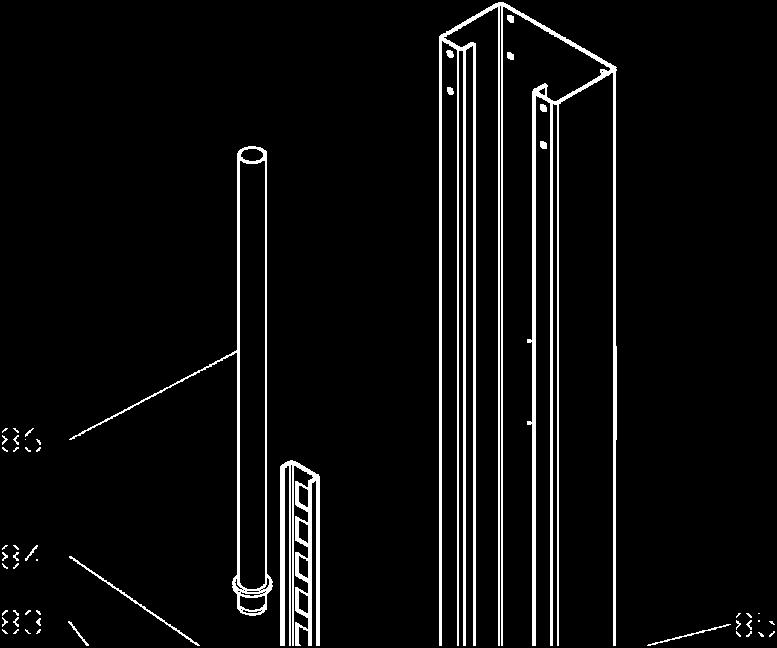
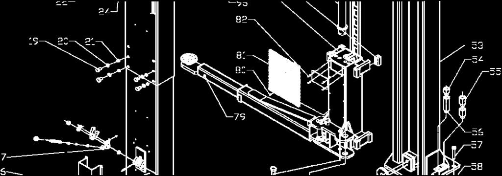
17 ILLUSTRATED PARTS BREAKDOWN Illustrated Parts Breakdown Information. Detailed illustrations and parts listings for the 10,000 Pound Two-Column Automotive Lift. Certain parts may be shown on more than one figure in order to illustrate their relationship with other components shown in the figure. Top beam assy Hose route 17

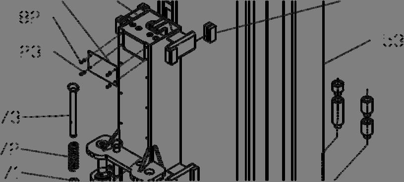

18 Post and Carriage assy 18


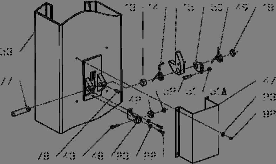
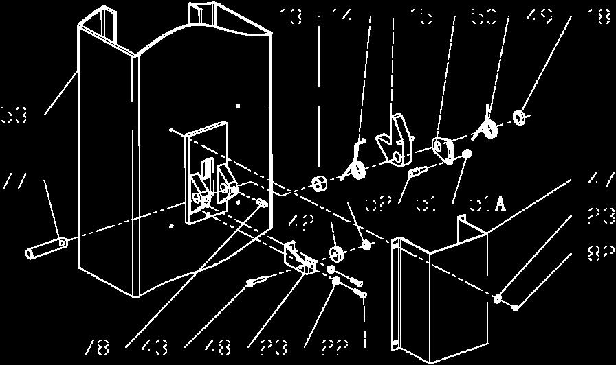
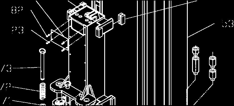
19 Safety device Power side Safety device off side Safety device 19

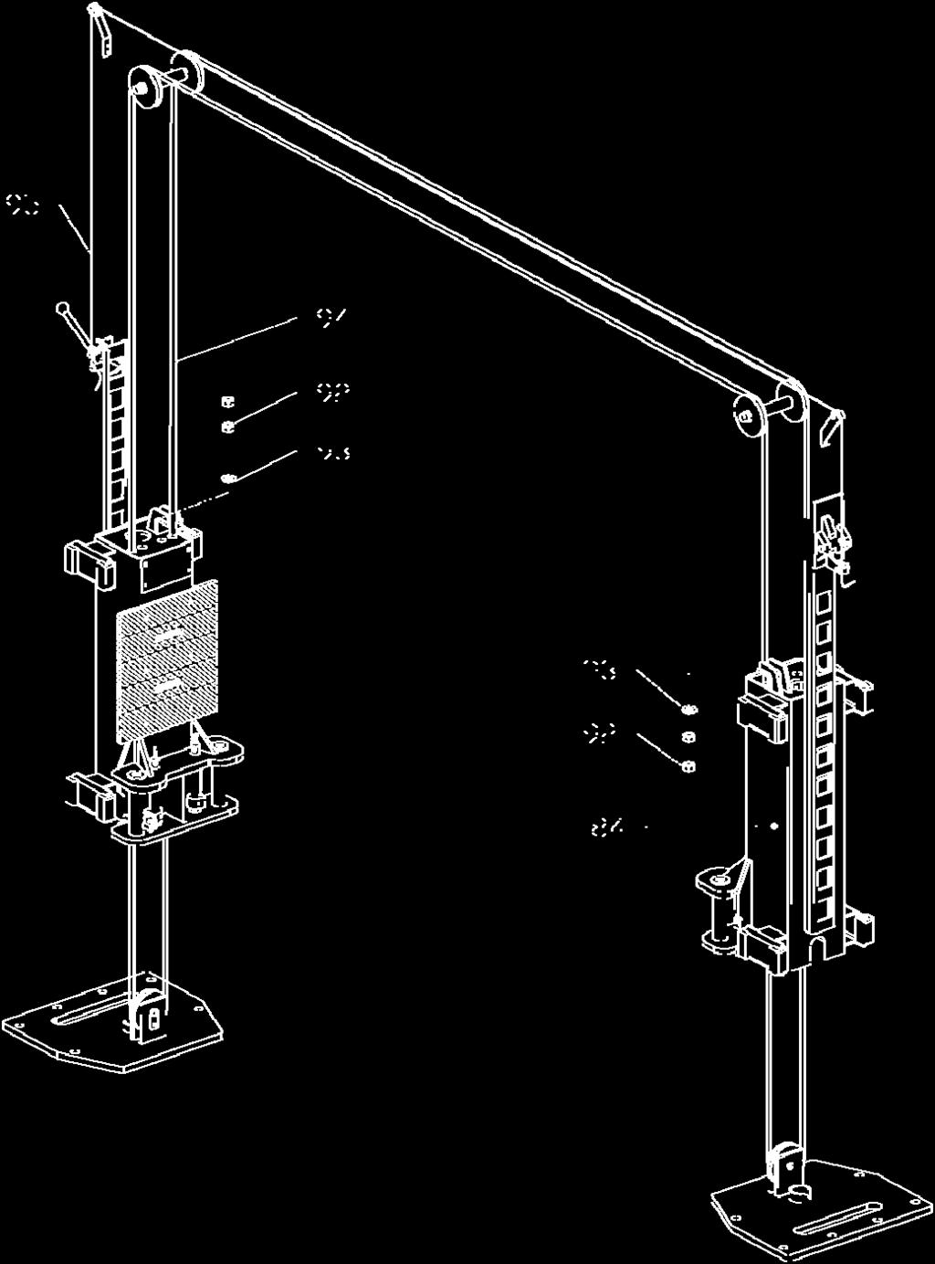
20 Cable route 20


21 Cable Connection High Setting Cable Top pulley Carriage Bottom pulley Low Setting Cable Top pulley Carriage Bottom pulley 21


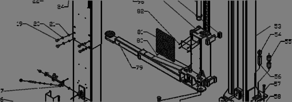
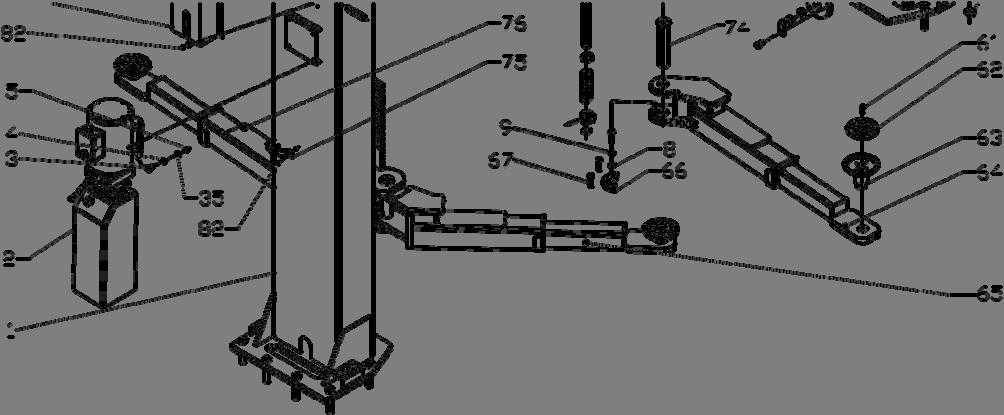
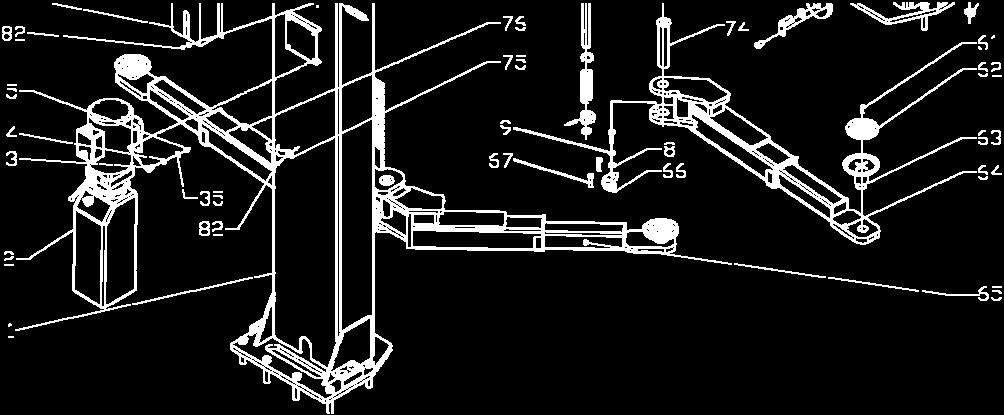
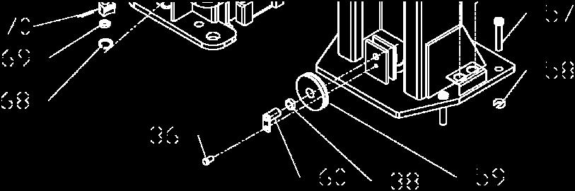
22 Exploded view Drive-in 22
23 PV-10/PV-10HP NO PART # DESCRIPTION QTY QTY NO PART # DESCRIPTION PV- PV- PV-10 PV POWER SIDE COLUMN HOSE SUPPORT POWER UNIT A PROTECTION M8*25 BOLT PLASTIC PULLEYP005A φ8 WASHER M10*35 BOLT M8 NUT TOP LOCK CABLE PULLEY POWER SIDE LOCK COVER COLUMN EXT MAIN CAM LOCK A φ10 WASHER NON POWER COVER φ10 LOCK WASHER SMALL CABLE PULLEY M10 NUT TORSION SPRING BLACK KNOB CAM LOCK LOCK HANDLE CABLE LOCK HOLD LARGE SPACER A SELF LOCKING NUT MAIN SPRING M10 SELF LOCKING MAIN LOCK NON POWER COLUMN M6*40 BOLT ADAPTER 1.5" M6 NUT ADAPTER 3" SMALL SPACER ADAPTER 6" M12*25 BOLTS ANCHOR 3/4"*5-1/2" φ12 LOCK WASHER SHIM M12 NUT BOTTOM PULLEY M6*20 BOLT BOTTOM PIM φ6 WASHER M6*25 BOLT M6 SELF LOCKING NUT RUBBER PAD LIMIT SWITCH FOOT PAD M5*12 BOLT LEFT FRONT ARM LIMIT BAR BRACE RIGHT FRONT ARM RIGHT OVERHEAD BAR HALF MOON GEAR B SPLIT PIN φ4* M10*30 ALLEN BOLT LIMIT BAR C-CLIP φ C LIMIT BAR LINK LIMIT RING A LIMIT BAR COVER ROLL PIN 6* LEFT OVERHEAD BAR GEAR RACK PIN STOP SPRING 26*φ31*φ φ8 WASHER LOCK PIN M8*15 BOLT ARM PIN TOP PULLEY HOSE CLAMP BRASS INSERT RIGHT REAR ARM SPACER MAIN LOCK PIN PIN SCREW M10* PIN SPACER LEFT REAR ARM
24 PV-10/PV-10HP (Cont.) NO PART # DESCRIPTION QTY QTY NO PART # DESCRIPTION PV- PV- PV- PV FLAT HEAD SCREW CYLINDER PIPE RUBBER PAD FITTING M6*8 SCREW CABLE NUT M PLATE CABLE NUT WASHER CARRIAGE CABLE SLIDE BLOCK A CYLINDER LOCK RELEASE CABLE A OVERHEAD HOSE A LIMIT SWITCH CABLE T-FITTING A SHORT HOSE
9,000 POUND TWO-COLUMN AUTOMOTIVE LIFT Model: NW-2-9KFP MANUAL
 9,000 POUND TWO-COLUMN AUTOMOTIVE LIFT Model: NW-2-9KFP MANUAL 1 9,000 POUND CAPACITY MODEL: NW-2-9KFP TWO-COLUMN AUTOMOTIVE LIFT READ THIS ENTIRE MANUAL BEFORE OPERATION BEGINS RECORD BELOW THE FOLLOWING
Floor Plate Style Lift And Overhead Beam Style Lift. Two Post Lift
 Floor Plate Style Lift And Overhead Beam Style Lift 9,000 POUND Two Post Lift ASSEMBLY & OPERATION INSTRUCTION TABLE OF CONTENTS Important Note Page 3 Definition Page 4 Preparation and General Information
9,000 POUND TWO-COLUMN AUTOMOTIVE LIFT. Model: NW-2-9KACD MANUAL
 9,000 POUND TWO-COLUMN AUTOMOTIVE LIFT Model: NW-2-9KACD MANUAL 1 9,000 POUND CAPACITY MODEL: NW-2-9KACD TWO-COLUMN AUTOMOTIVE LIFT READ THIS ENTIRE MANUAL BEFORE OPERATION BEGINS RECORD BELOW THE FOLLOWING
Model: TPO310-ACX MANUAL
 PEAK-AUTOLIFT 10,000 POUND TWO-COLUMN AUTOMOTIVE LIFT Model: TPO310-ACX MANUAL AutoTool 2739 W 79 th St #16 Hialeah, FL 33016 Phone: (305) 825-9600 www.autotool.net Rev. 2010 Table of Contents WARRANTY...3
ATD2P11BS. Two-Post Clear Floor Bi-Symmetric Automotive Lift. Installation & Operation Manual. 11,000 lbs. Capacity. (2,750 lbs.
 Two-Post Clear Floor Bi-Symmetric Automotive Lift 11,000 lbs. Capacity (2,750 lbs. Max per Arm) Installation & Operation Manual 1. Safety Information 1.1 Note, Caution and Warning 1.2 Important Information
Read this entire manual before operation begins.
 Read this entire manual before operation begins. Record below the following information which is located on the serial number data plate. Serial No. Model No. Date of Installation Contents Important Information........
Model FP12K-K Flat Deck Four-Post Lift
 Model FP12K-K Flat Deck Four-Post Lift (12,000LBS Capacity) ASSEMBLY & OPERATION INSTRUCTION 2006.4. TABLE OF CONTENTS Important Note--------------------------------------------------------------------------------Page
INSTALLATION / OWNERS MANUALS
 Floor Plate Automotive Lift 9,000 POUND CAPACITY IMPORTANT Reference ANSI/ALI ALIS, Safety Requirements for Installation and Service of Automotive Lifts before installing lift. INSTALLATION / OWNERS MANUALS
TWO POST LIFT INSTALLATION AND OWNERS MANUAL. January 2008 rev. E I MAN
 TWO POST LIFT INSTALLATION AND OWNERS MANUAL DP15, DP15-2 Capacity 15,000 lbs. January 2008 rev. E 1. TABLE OF CONTENTS 2. Important Information.. 2 3. Section 1 Owner s Manual Safety Instructions... 3
TP15KC-KX Two-Post Clear Floor Lift
 TP15KC-KX Two-Post Clear Floor Lift (Symmetric) 15,000 lbs. Capacity (3,750 lbs. Max per Arm) ASSEMBLY & OPERATION INSTRUCTION MANUAL Feb. 2017 IMPORTANT NOTES READ THE INSTALLATION AND OPERATION MANUAL
INSTALLATION MANUAL & OPERATION INSTRUCTIONS. OVERHEAD CAR LIFT 2-POST LIFT AUTO HOIST APlusLift HW-10KOH
 INSTALLATION MANUAL & OPERATION INSTRUCTIONS OVERHEAD CAR LIFT 2-POST LIFT AUTO HOIST APlusLift HW-10KOH 1 READ THIS MANUAL COMPLETELY BEFORE INSTALLING LIFT!!! DISTRIBUTED BY: Songa Enterprises LLC 8512
SCISSOR LIFT Model MR6K-38 /161108A 6,000lb Capacity Operation Manual
 SCISSOR LIFT Model MR6K-38 /161108A 6,000lb Capacity Operation Manual (Version A) 2009. Apr. CONTENT 1. Safety Note, Caution and Warning Important Information Safety Instructions 2. Technical Manual Product
2-Post Lift Operations and Maintenance Manual
 2-Post Lift Operations and Maintenance Manual Table Of Contents Safety Instructions... 2 Owner/Employer Responsibilities / Operating Conditions... 3 Operating Instructions... 4 Maintenance Instructions...
ATD-2P9A 9,000 lbs. Two Post Clear Floor Lift Owner s Manual
 ATD-2P9A 9,000 lbs. Two Post Clear Floor Lift Owner s Manual Features: Specifications: IMPORTANT NOTES READ THE INSTALLATION AND OPERATION MANUAL IN ITS ENTIRETY BEFORE ATTEMPTING TO INSTALL THE LIFT.
INSTALLATION & OPERATION MANUAL
 Two-Post Clear Floor Lift (Asymmetric) 9,000 lbs. Capacity (2,250 lbs. Max per Arm) INSTALLATION & OPERATION MANUAL IMPORTANT NOTES READ THE INSTALLATION AND OPERATION MANUAL IN ITS ENTIRETY BEFORE ATTEMPTING
FOUR-POST LIFT. 14,000 lbs. Capacity
 FOUR-POST LIFT 14,000 lbs. Capacity Note: At the rated capacity of 14,000 lbs. lift was designed for: 101" Minimum wheelbase for models without rolling jacks 124" Minimum wheelbase for models with rolling
TWO POST LIFT INSTALLATION AND OWNERS MANUAL
 TWO POST LIFT INSTALLATION AND OWNERS MANUAL DP15, DP15-2 Capacity 15,000 lbs. 1. TABLE OF CONTENTS 2. Important Information.. 2 3. Section 1 Owner s Manual Safety Instructions... 3 Monthly Maintenance...
ATTENTION. 1. Do not attempt to use the power unit to extend your cylinder. This must be done manually.
 NSS8XLT Installation Manual ATTENTION By following the instructions in this manual you can save yourself much time, frustration and money. The installation of your lift will take 4-5 hours. Do not rush.
Drop Tail Motorcycle Lift 1,000 lbs. capacity Installation, Safety, Operation, Maintenance
 Drop Tail Motorcycle Lift 1,000 lbs. capacity Installation, Safety, Operation, Maintenance Entire contents 2009 by Direct Lift. All rights reserved. IN50012 CO7338.1 Rev. B 03/30/2009 Inspection upon receipt
Motorcycle Lift 1,000 lbs. capacity Installation, Safety, Operation, Maintenance
 Motorcycle Lift 1,000 lbs. capacity Installation, Safety, Operation, Maintenance Entire contents 2008 by RL Consolidated, Inc. All rights reserved. 994358 CO7297 Rev. F 12/17/2008 Inspection upon receipt
Model FP14KA-C Alignment Four-Post Lift
 Model FP14KA-C Alignment Four-Post Lift (14000 LBS Capacity) ASSEMBLY & OPERATION INSTRUCTION 2006.4. TABLE OF CONTENTS Important Note--------------------------------------------------------------------------------Page
TL4.0OHDI (9KOH) INSTALLATION / OWNERS MANUAL
 INSTALLATION / OWNERS MANUAL") TL4.0OHDI (9KOH) INSTALLATION / OWNERS MANUAL TWO POST HOIST Capacity: 4 TONNE Read this manual thoroughly before installing, operating, or maintaining this lift. When done with installation be sure to
TL4.0OHDI (9KOH) INSTALLATION / OWNERS MANUAL TWO POST HOIST Capacity: 4 TONNE Read this manual thoroughly before installing, operating, or maintaining this lift. When done with installation be sure to
Installation Instructions Capacity 10,000 lbs. (100 Series Lift)
") Installation Instructions Capacity 10,000 lbs. (100 Series Lift) IMPORTANT Reference ANSI/ALI ALIS, Safety Requirements for Installation and Service of Automotive Lifts before installing lift. OPERATING
Installation Instructions Capacity 10,000 lbs. (100 Series Lift) IMPORTANT Reference ANSI/ALI ALIS, Safety Requirements for Installation and Service of Automotive Lifts before installing lift. OPERATING
Model FP14KO-A Wheel alignment & Open Front Four-Post Lift
 Model FP14KO-A Wheel alignment & Open Front Four-Post Lift ( 14000LBS / 6300Kg Capacity) ASSEMBLY & OPERATION INSTRUCTIONS ( Series T1) 2009.7. INTRODUCTION Model FP14KO-A is a four-post lift is used in
TWO POST LIFT INSTALLATION AND OWNERS MANUAL Capacity 10,000 lbs.
 TWO POST LIFT INSTALLATION AND OWNERS MANUAL Capacity 10,000 lbs. October 2012 by Vehicle Service Group All rights reserved. CO8347 IN60009 Rev. H 10/18/2012 TABLE OF CONTENTS Important Information...2
TWO POST LIFT INSTALLATION AND OWNERS MANUAL Capacity 10,000 lbs.
 TWO POST LIFT INSTALLATION AND OWNERS MANUAL Capacity 10,000 lbs. May 2009 All rights reserved. CO7378.2 IN60005 Rev. - 5/7/2009 TABLE OF CONTENTS Important Information...2 Section 1 Owner s Manual Safety
Read this entire manual before operation begins.
 Read this entire manual before operation begins. Record below the following information which is located on the serial number data plate. Serial No. Model No. Date of Installation Contents Important Information........
ATD-4P9DXL. Four Post Lift. 9,000 lbs. Capacity. (4,500 lbs. per axle) INSTALLATION / OWNERS MANUAL
 INSTALLATION / OWNERS MANUAL") ATD-4P9DXL Four Post Lift 9,000 lbs. Capacity (4,500 lbs. per axle) INSTALLATION / OWNERS MANUAL Jan 2017 READ THIS MANUAL THOROUGHLY BEFORE INSTALLING, OPERATING, OR MAINTAINING THIS LIFT. WHEN DONE WITH
ATD-4P9DXL Four Post Lift 9,000 lbs. Capacity (4,500 lbs. per axle) INSTALLATION / OWNERS MANUAL Jan 2017 READ THIS MANUAL THOROUGHLY BEFORE INSTALLING, OPERATING, OR MAINTAINING THIS LIFT. WHEN DONE WITH
ATO7 (100 Series Lifts)
") O PE ATO7 (100 Series Lifts) Capacity 7000 lbs. (3181 kg) 1750 lbs. (795.25 kg) per arm R A TI O N & M AI N TE N A N N CE Table Of Contents Safety Instructions... 2 Owner/Employer Responsibilities / Operating
O PE ATO7 (100 Series Lifts) Capacity 7000 lbs. (3181 kg) 1750 lbs. (795.25 kg) per arm R A TI O N & M AI N TE N A N N CE Table Of Contents Safety Instructions... 2 Owner/Employer Responsibilities / Operating
Lifting height 5.5" - 72" with adapters " Height overall 165" Width between columns 122" Drive through 109" Width overall 151.
 Model Number TP12KC-D Capacity 12,000 lbs. Lifting height 5.5" - 72" with adapters 79.625" Height overall 165" Width between columns 122" Drive through 109" Width overall 151.125" Arm extension 37.5" -
SPOA10NB, SPOA10, SPO10 ( Series Lifts) SPOA7, SPOA9, SPO9 (500 Series Lifts)
 SPOA7, SPOA9, SPO9 (500 Series Lifts)") O PE SPOA10NB, SPOA10, SPO10 (200-700 Series Lifts) SPOA7, SPOA9, SPO9 (500 Series Lifts) SPOA7 Capacity 7,000 lbs. SPOA9, SPO9 Capacity 9,000 lbs. SPOA10NB, SPOA10, SPO10 Capacity 10,000 lbs. R A TI O
O PE SPOA10NB, SPOA10, SPO10 (200-700 Series Lifts) SPOA7, SPOA9, SPO9 (500 Series Lifts) SPOA7 Capacity 7,000 lbs. SPOA9, SPO9 Capacity 9,000 lbs. SPOA10NB, SPOA10, SPO10 Capacity 10,000 lbs. R A TI O
Read this entire manual before operation begins.
 Read this entire manual before operation begins. Record below the following information which is located on the serial number data plate. Serial No. Model No. Date of Installation Contents Important Information........
BLAZER 9000 LUBE LIFT OPERATOR AND PARTS MANUAL
 BLAZER 9000 LUBE LIFT OPERATOR AND PARTS MANUAL Blazer 9000 Lube Lift Operator s Manual Note: Instructions must be read thoroughly before installing, operating, or maintaining the lift. Devon Lube Center
CONTENTS. Product Features and Specifications Installation Requirement Installation Exploded View Operation Instruction...
 1 CONTENTS Product Features and Specifications... 3 Installation Requirement... 5 Installation... 6 Exploded View... 20 Test... 22 Operation Instruction... 25 Maintenance... 26 Trouble Shooting... 27 Parts
PP8S Four Post Lift 8,000 lbs. Capacity
 PP8S Four Post Lift 8,000 lbs. Capacity (4,000 lbs. per axle) Minimum wheelbase 100" at rated capacity IMPORTANT INSTALLATION / OWNERS MANUAL Read this manual thoroughly before installing, operating, or
Atlas PV-9WP Addendum
 Atlas PV-9WP Addendum 9,000 lb. Capacity Two-Post Overhead Lift The Atlas PV-9WP above ground hoist is 6 inches wider than the Atlas PV-9P, giving it an overall width of 141 (11 9 ) and a drive thru width
SL210i/SL212i/SL19i. Table Of Contents
 SL210i/SL212i/SL19i (700 Series) SL19i Capacity 9,000 lbs. SL210i Fixed Pad Capacity 9,000 lbs. SL210i Capacity 10,000 lbs. SL212i Capacity 12,000 lbs. Table Of Contents Owner/Employer Responsibilities...
Installation Instructions Capacity 10,000 lbs. DP10 (200 Series Lift)
") Installation Instructions Capacity 10,000 lbs. DP10 (200 Series Lift) IMPORTANT Reference ANSI/ALI ALIS, Safety Requirements for Installation and Service of Automotive Lifts before installing lift. OPERATING
Installation Instructions Capacity 10,000 lbs. DP10 (200 Series Lift) IMPORTANT Reference ANSI/ALI ALIS, Safety Requirements for Installation and Service of Automotive Lifts before installing lift. OPERATING
TP10KACD REV A
 TP10KACD 10, 000l bcapaci t y TwoPostAsymmet r i caut oli f t REV A-061813 Table of contents Important Information Section 1 Owner s Manual Safety Instructions Monthly Maintenance Troubleshooting Section
MR6K lb Capacity Portable Mid-Rise Scissor Lift. Operation Manual
 MR6K-38 6000 lb Capacity Portable Mid-Rise Scissor Lift Operation Manual 6,000 LB. PORTABLE MID-RISE FRAME LIFT A comfortable 38 working height, twin cylinders and double safety locks make this portable
IMPORTANT INFORMATION
 1 TABLE OF CONTENTS IMPORTANT INFORMATION... pg 2 LIFT SPECIFICATIONS & FLOOR PLAN... pg 3 TOOLS REQUIRED... pg 4 INSTALLATION INSTRUCTIONS... pg 4 CASTER KIT ASSEMBLY / INSTALLATION... pg 6 FOUNDATION
ATD-4P14CCA 14,000 lb Capacity Closed Front Alignment Lift ASSEMBLY & OPERATION INSTRUCTION MANUAL
 ATD-4P14CCA 14,000 lb Capacity Closed Front Alignment Lift ASSEMBLY & OPERATION INSTRUCTION MANUAL 14,000 LB. FOUR POST CABLE DRIVEN ALIGNMENT LIFT ATD-4P14CCA 14,000 lb. capacity Four post Cable driven
If facility voltage is different, refer to set-up instructions. IMPORTANT This lift is wired and adjusted to operate at 230 volts.
 MODEL 40/50K Installation And Owner s Manual (000Series) Capacity 40,000 lbs. (20,000 lbs. per axle) Capacity 50,000 lbs. (25,000 lbs. per axle) Four Post Surface Mounted Lift IMPORTANT This lift is wired
Read this entire manual before operation begins.
 Read this entire manual before operation begins. Record below the following information which is located on the serial number data plate. Serial No. Model No. Date of Installation Contents Important Information........
FP8K-B, FP8K-DX & FP8K-DX-XLT Four Post Storage Lifts
 FP8K-B, FP8K-DX & FP8K-DX-XLT Four Post Storage Lifts 8,000 lbs. Capacity (4,000 lbs. per axle) INSTALLATION / OWNERS MANUAL READ THIS MANUAL THOROUGHLY BEFORE INSTALLING, OPERATING, OR MAINTAINING THIS
Drop Tail Motorcycle Lift 1,000 lbs. capacity Installation, Safety, Operation, Maintenance
 Drop Tail Motorcycle Lift 1,000 lbs. capacity Installation, Safety, Operation, Maintenance Entire contents 2011 by Vehicle Service Group. All rights reserved. IN50012 CO7932 Rev. C 04/20/2011 Inspection
CONTENTS. Product Features and Specifications Installation Requirement Steps of Installation 4. Exploded View Test Run...
 CONTENTS Product Features and Specifications... 1 Installation Requirement... 3 Steps of Installation 4 Exploded View... 14 Test Run... 16 Operation Instruction... 19 Maintenance... 20 Trouble Shooting...
CONTENTS. Product Features and Specifications...1. Installation Requirement Steps of Installation.. 5. Exploded View Test Run...
 CONTENTS Product Features and Specifications...1 Installation Requirement... 3 Steps of Installation.. 5 Exploded View...18 Test Run...21 Operation Instruction...22 Maintenance... 23 Trouble Shooting...
SPO15, SPO18 I N S T A L L A T I O N I N S T R U C T I O N S
 SPO15, SPO18 Sprinter SPO15 (3A0 Lifts) Capacity 11,000 lbs. Standard SPO15 (300 Series Lifts) Capacity 15,000 lbs. Standard SPO18 (300 Series Lifts) Capacity 18,000 lbs. SPO15 (31A0 Lifts) Capacity 14,300
Read this entire manual before operation begins.
 Read this entire manual before operation begins. Record below the following information which is located on the serial number data plate. Serial No. Model No. Date of Installation Contents Specifications.............
Installation Instructions
 Installation Instructions 2-Post Capacity 12,000 lbs. OPERATING CONDITIONS Lift is not intended for outdoor use and has an operating ambient temperature range of 41-104 F (5-40 C) IMPORTANT Reference ANSI/ALI
TP12KC-DX. Two Post Clear Floor. Automotive Lift. 12,000 lb. Capacity. (3,000 lbs. Max Capacity per Arm) Installation & Operation Manual
 Installation & Operation Manual") Two Post Clear Floor Automotive Lift 12,000 lb. Capacity (3,000 lbs. Max Capacity per Arm) Installation & Operation Manual IMPORTANT!! READ MANUAL THOROUGHLY BEFORE INSTALLING, OPERATING, SERVICING OR
Two Post Clear Floor Automotive Lift 12,000 lb. Capacity (3,000 lbs. Max Capacity per Arm) Installation & Operation Manual IMPORTANT!! READ MANUAL THOROUGHLY BEFORE INSTALLING, OPERATING, SERVICING OR
Models PR-12F PR-12C PR-15C SURFACE MOUNTED TWO-POST LIFTS INSTALLATION AND OPERATION MANUAL
 Forward this manual to all operators. Failure to operate this equipment as directed may cause injury. INSTALLATION AND OPERATION MANUAL SURFACE MOUNTED TWO-POST LIFTS Models PR-12F PR-12C PR-15C Keep this
Read this entire manual before operation begins.
 Read this entire manual before operation begins. Record below the following information which is located on the serial number data plate. Serial No. Model No. Date of Installation Contents Specifications.............
Read this entire manual before operation begins.
 Read this entire manual before operation begins. Record below the following information which is located on the serial number data plate. Serial No. Model No. Date of Installation Contents Specifications.............
FP8K-B, FP8K-DX & FP8K-DX-XLT Four Post Storage Lifts
 FP8K-B, FP8K-DX & FP8K-DX-XLT Four Post Storage Lifts 8,000 lbs. Capacity (4,000 lbs. per axle) INSTALLATION / OWNERS MANUAL READ THIS MANUAL THOROUGHLY BEFORE INSTALLING, OPERATING, OR MAINTAINING THIS
T R I N S I N S U C N S
 R O TA R Y V A L I D A T E D CERTIFIED B Y E L T SPOA7, SPOA9, SPO9 Two Post Surface Mounted Lift (200 Series Lifts) SPOA7 Capacity 7,000lbs. SPOA9 Capacity 9,000lbs. 1750 lbs. per arm 2250 lbs. per arm
INSTALLATION, OPERATION & MAINTENANCE MANUAL
 INSTALLATION, OPERATION & MAINTENANCE MANUAL Two Post Surface Mounted Lift MODEL X10 10,000 LBS. CAPACITY 2500 LBS. PER ARM 200 Cabel Street, P.O. Box 3944 Louisville, Kentucky 40201-3944 Email:sales@challengerlifts.com
Read this entire manual before operation begins.
 Read this entire manual before operation begins. Record below the following information which is located on the serial number data plate. Serial No. Model No. Date of Installation Contents Specifications.............
ASSEMBLY & OPERATION INSTRUCTION MANUAL
 Sliding Bridge Jack 3,500 lbs. Capacity ASSEMBLY & OPERATION INSTRUCTION MANUAL TABLE OF CONTENTS Specifications... 2 Description & Features... 3 Installation Instructions... 4 Safety Instructions... 4
PP8 Plus Long Four Post Lift 8,000 lbs. Capacity
 PP8 Plus Long Four Post Lift 8,000 lbs. Capacity (4,000 lbs. per axle) Minimum wheelbase 115 at rated capacity IMPORTANT Reference ANSI/ALI ALIS, Safety Requirements for Installation and Service of Automotive
MSC-6KLP Low Profile Mobile Single Column Lift. 6,000 lb. Capacity (1,500 lbs. Max Capacity per Arm) Installation & Operation Manual
 Installation & Operation Manual") Low Profile Mobile Single Column Lift 6,000 lb. Capacity (1,500 lbs. Max Capacity per Arm) Installation & Operation Manual INDEX PREFACE-------------------------------------------------------------------------------
Low Profile Mobile Single Column Lift 6,000 lb. Capacity (1,500 lbs. Max Capacity per Arm) Installation & Operation Manual INDEX PREFACE-------------------------------------------------------------------------------
CONTENTS. Product Features and Specifications...1. Installation Requirement...3. Steps of Installation...4. Exploded View Test Run...
 TP10AS 2-POST LIFT CONTENTS Product Features and Specifications...1 Installation Requirement...3 Steps of Installation...4 Exploded View...24 Test Run....28 Operation Instruction...29 Maintenance...30
It is the shop owner's responsibility to train all operators in lift operation and safety.
 2 Your new lift will provide years of dependable service if installed, operated and maintained properly. Read and be prepared to follow all safety, installation, operation, and maintenance instructions
Challenger Lifts, Inc. MODEL 12000
 Challenger Lifts, Inc. MODEL 12000 TWO POST SURFACE MOUNTED LIFT OPERATION, INSTALLATION & MAINTENANCE MANUAL IMPORTANT READ THIS MANUAL COMPLETELY BEFORE INSTALLING OR OPERATING THE LIFT 200 CABEL STREET,
Two Post Surface Mounted Lift 12,000 LBS. CAPACITY 3000 LBS. PER ARM
 INSTALLATION, OPERATION & MAINTENANCE MANUAL Two Post Surface Mounted Lift MODEL EELR537A 12,000 LBS. CAPACITY 3000 LBS. PER ARM Snap-On Equipment 309 Exchange Avenue, Conway, Arkansas, 72032 Tel: 501-450-1500
INSTALLATION and OPERATION MANUAL
 INSTALLATION and OPERATION MANUAL AC2012S 12,000 12,000 LB. LB. (SYMMETRICAL) READ and SAVE THIS INSTRUCTION MANUAL P.O. Box 15540 Richmond, VA 23227 804-798-8922 www.accu-turn.com 1-800-551-2228 APR 2004
GLO-8000 SERIES (GLO-8000 & GLO-8000XLT)
") GLO-8000 SERIES (GLO-8000 & GLO-8000XLT) 8,000 LBS. CAPACITY FOUR-POST STORAGE LIFT INSTALLATION & OPERATION MANUAL SERIAL NUMBER: INSTALLATION DATE: EAGLE EQUIPMENT 1-800-336-2776 REV2011 03.0 BD SHIPPING
GLO-8000 SERIES (GLO-8000 & GLO-8000XLT) 8,000 LBS. CAPACITY FOUR-POST STORAGE LIFT INSTALLATION & OPERATION MANUAL SERIAL NUMBER: INSTALLATION DATE: EAGLE EQUIPMENT 1-800-336-2776 REV2011 03.0 BD SHIPPING
Read this entire manual before operation begins.
 Read this entire manual before operation begins. Record below the following information which is located on the serial number data plate. Serial No. Model No. Date of Installation Contents Specifications.............
WHIP INDUSTRIES, INC.
 WHIP INDUSTRIES, INC. WFP30R, WFP30R-E & WFP30R-EE STD., EXT. & E-EXT. 30,000 LBS CAPACITY FOUR POST ABOVE GROUND LIFT INSTALLATION INSTRUCTIONS & MANUAL WHIP INDUSTRIES, INC 3010 S MAIN ST. FORT WORTH,
Electro-Hydraulic / UTV Lift Bench U-2200IEH-XR
 Electro-Hydraulic / UTV Lift Bench with Retractable Ramp Capacity 2,200lbs Installation, Operation & Maintenance Manual CONTENT 1. Safety Information 1.1 Note, Caution and Warning 1.2 Important Information
Cargolift 85 Pv Repair. Cargolift 90 Sa Standard. Cargolift 120 Saav Jumbo. Cargolift 120 F Drive-on IMPORTANT
 Installation, Operation and Maintenance Manual For Cargolift 85 Pv Repair Cargolift 90 Sa Standard Cargolift 120 Saav Jumbo Cargolift 120 F Drive-on IMPORTANT Read this manual throughoutly before installing,
Wallace Tri-Adjustable Gantry Cranes Square Tube Assembly Instructions
 Wallace Tri-Adjustable Gantry Cranes Square Tube Assembly Instructions For any additional information, Please call 1- S 1. Read and understand instructions before using this gantry. 2. Inspect gantry thoroughly
Challenger Lifts, Inc. MODELS & 18000
 Challenger Lifts, Inc. MODELS 15000 & 18000 TWO POST SURFACE MOUNTED LIFT OPERATION, INSTALLATION & MAINTENANCE MANUAL IMPORTANT READ THIS MANUAL COMPLETELY BEFORE INSTALLING OR OPERATING THE LIFT 200
Installation Instructions X-Force UTV Lift (000 Series) Capacity 2,275 lbs (1,035 kg)
 Capacity 2,275 lbs (1,035 kg)") Installation Instructions X-Force UTV Lift (000 Series) Capacity 2,275 lbs (1,035 kg) Read entire manual before assembling, installing, operating, or servicing this equipment. LP20640 IN20793 September
Installation Instructions X-Force UTV Lift (000 Series) Capacity 2,275 lbs (1,035 kg) Read entire manual before assembling, installing, operating, or servicing this equipment. LP20640 IN20793 September
MODEL QMR6 PORTABLE MID-RISE LIFT 6,000 lb Capacity 1500 lb Per Arm INSTALLATION, OPERATION AND MAINTENANCE MANUAL
 MODEL QMR6 PORTABLE MID-RISE LIFT 6,000 lb Capacity 1500 lb Per Arm INSTALLATION, OPERATION AND MAINTENANCE MANUAL IMPORTANT!!! READ THIS MANUAL COMPLETELY BEFORE INSTALLING OR OPERATING THE LIFT 200 CABEL
EZ LINER EXPRESS USERS MANUAL
 EZ LINER EXPRESS 2013 Vehicle Service Group CHIEF'S LIMITED ONE-YEAR WARRANTY & LIABILITY Chief Automotive Technologies warrants for one year from date of installation and/or purchase any components of
READ THIS MANUAL BEFORE INSTALLATION AND/OR OPERATION! WARNING:
 1 READ THIS MANUAL BEFORE INSTALLATION AND/OR OPERATION! This is a vehicle lift operation manual and no attempt is made or implied herein to instruct the user in lifting methods particular to an individual
ASSEMBLY & OPERATION INSTRUCTION MANUAL
 LR-26-PAD 6000 lb Capacity Low-Rise Pad Lift ASSEMBLY & OPERATION INSTRUCTION MANUAL 6,000 LB. LOW-RISE PAD LIFT Easy frame lifting on padded runways. Great for wheel and brake work, tire and wheel changing
Two Post Surface Mounted Lift 10,000 LBS. CAPACITY 2500 LBS. PER ARM
 INSTALLATION, OPERATION & MAINTENANCE MANUAL Two Post Surface Mounted Lift MODEL LE10 10,000 LBS. CAPACITY 2500 LBS. PER ARM 2311 South Park Rd Louisville, Kentucky 40219 Email:sales@challengerlifts.com
Package Contents Part A (3) I-Beam (1) Base (2) Other parts
 I-Beam (1) Base (2) Other parts") Page 1 Installation Instructions for 81245 Adjustable Height Gantry Crane 1-Ton Capacity Table of Contents Important Safety Information pg. 2 Specific Operation Warnings pg. 2 Main Parts of Product pg.
Page 1 Installation Instructions for 81245 Adjustable Height Gantry Crane 1-Ton Capacity Table of Contents Important Safety Information pg. 2 Specific Operation Warnings pg. 2 Main Parts of Product pg.
CONTENTS. Product Features and Specifications...1. Installation Requirement Steps of Installation.. 5. Exploded View Test Run...
 CONTENTS Product Features and Specifications...1 Installation Requirement... 4 Steps of Installation.. 5 Exploded View...21 Test Run...26 Operation Instruction...27 Maintenance... 28 Trouble Shooting...
Read this entire manual before operation begins.
 Revised 9/5/2018 Read this entire manual before operation begins. Record below the following information which is located on the serial number data plate. Serial No. Model No. Date of Installation Contents
Installation Manual. Installation Instructions. Operation. TP15KC Parts Check List Notes about your TP15KC lift
 Installation Manual Parts Check List Notes about your lift Installation Instructions Step 1 Measure lift area and check for defects Step 2 Cylinder assembly Step 3 Position columns and uprights, level
INSTALLATION and OPERATION MANUAL
 INSTALLATION and OPERATION MANUAL 10K 2N1 2 POST V-SERIES SV210S - R/B/M,1/3 D210S - R/B/M,1/3 READ and SAVE THIS INSTRUCTION MANUAL JUNE 2007 6-3255 Table of Contents 1.0 SAFETY AND OPERATING INSTRUCTIONS...3
GLO-7000 SERIES (GLO-7000 & GLO-7000XLT)
") GLO-7000 SERIES (GLO-7000 & GLO-7000XLT) 7,000 LBS. CAPACITY FOUR-POST STORAGE LIFT (BLUE) INSTALLATION & OPERATION MANUAL SERIAL NUMBER: INSTALLATION DATE: EAGLE EQUIPMENT 1-800-336-2776 (STANDARD) SHIPPING
GLO-7000 SERIES (GLO-7000 & GLO-7000XLT) 7,000 LBS. CAPACITY FOUR-POST STORAGE LIFT (BLUE) INSTALLATION & OPERATION MANUAL SERIAL NUMBER: INSTALLATION DATE: EAGLE EQUIPMENT 1-800-336-2776 (STANDARD) SHIPPING
CR30 Installation Instruction Capacity 30,000 lbs. (15,000 lbs. per axle) 235 /271 /308 Wheelbases 140 Minimum Wheelbase
 235 /271 /308 Wheelbases 140 Minimum Wheelbase") CR0 Installation Instruction Capacity 0,000 lbs. (,000 lbs. per axle) /7 /08 Wheelbases 40 Minimum Wheelbase January 009 CO70 INS0449 Rev. - /08/009 Required Clearances REAR 8' 0" Min. To Nearest Obstruction
CR0 Installation Instruction Capacity 0,000 lbs. (,000 lbs. per axle) /7 /08 Wheelbases 40 Minimum Wheelbase January 009 CO70 INS0449 Rev. - /08/009 Required Clearances REAR 8' 0" Min. To Nearest Obstruction
Model Q4P12E and Q4P12X
 INSTALLATION, OPERATION & MAINTENANCE MANUAL Four Post Surface Mounted Lift Model Q4P2E and Q4P2X Closed Front (2,000 lb Capacity) 200 Cabel Street, P.O. Box 3944 Louisville, Kentucky 4020-3944 Email:sales@Qualitylifts.com
Parallel Lift Rack MODEL RM
 Form 4401T, 09-03 Supersedes Form 4401T, 10-00 OPERATION INSTRUCTIONS Parallel Lift Rack MODEL RM Copyright 1998-2003 Hunter Engineering Company Contents 1. For Your Safety... 1 1.1 Warning/Instruction
MIDRISE MODEL SM60F_1 // SM60F_A 6,500 LB. CAPACITY
 INSTALLATION and OPERATION MANUAL READ THIS INSTRUCTION MANUAL THOROUGHLY BEFORE INSTALLING, OPERATING, SERVICING OR MAINTAINING THE LIFT. SAVE THIS MANUAL. NOV 2007 REV.B MIDRISE MODEL SM60F_1 // SM60F_A
Read this entire manual before operation begins.
 Rev. 12/12/2017 Read this entire manual before operation begins. Record below the following information which is located on the serial number data plate. Serial No. Model No. Date of Installation Contents
Model Q4P12E and Q4P12X
 INSTALLATION, OPERATION & MAINTENANCE MANUAL Four Post Surface Mounted Lift Model Q4P2E and Q4P2X Closed Front (2,000 lb Capacity) 200 Cabel Street, P.O. Box 3972 Louisville, Kentucky 4020-3972 Email:sales@Qualitylifts.com
Installation, Operation & Maintenance Manual. Surface Mounted Lift 10,000 LBS. CAPACITY 2500 LBS. PER ARM
 Installation, Operation & Maintenance Manual VersymmetricTM Two Post Surface Mounted Lift MODEL CL10 10,000 LBS. CAPACITY 2500 LBS. PER ARM 200 Cabel Street, P.O. Box 3944 Louisville, Kentucky 40201-3944
SHIPPING DAMAGE CLAIMS
 INSTRUCTION MANUAL ADMIRAL 9000 SERIES Revision B 3-2011 pn# 199822 PLEASE READ THE ENTIRE CONTENTS OF THIS MANUAL PRIOR TO INSTALLATION AND OPERATION. BY PROCEEDING, YOU AGREE THAT YOU FULLY UNDERSTAND
6722 Rev. A CAPACITY: 22 TON TRUCK AXLE JACK WITH AIR RETURN
 CONTENTS: Page Specifications 2 Warning Information Setup Instructions and Operating Instructions 4 Preventative Maintenance, Inspection and Proper Storage 5 Troubleshooting, Owner/User Responsibility
Two Post Surface Mounted Lift 12,000 LBS. CAPACITY 3000 LBS. PER ARM
 INSTALLATION, OPERATION & MAINTENANCE MANUAL Two Post Surface Mounted Lift MODEL Q12 12,000 LBS. CAPACITY 3000 LBS. PER ARM 200 Cabel Street, P.O. Box 3944, Louisville, Kentucky 40206 Email:sales@qualitylifts.com
Installation and Operation Manual
 1645 Lemonwood Dr. Santa Paula, CA 93060 USA Toll Free: 1 (800) 253-2363 Tel: 1 (805) 933-9970 rangerproducts.com Ranger Floor Jack Installation and Operation Manual Manual Revision B July 2017 Manual
Hydraulic Hand Pallet Trucks
 Operating Instructions & Parts Manual 12U124 Please read and save these instructions. Read carefully before attempting to assemble, install, operate, or maintain the product described. Protect yourself
MODEL CL10. Versymmetric Two Post. Surface Mounted Lift. Installation, Operation & Maintenance Manual
 Installation, Operation & Maintenance Manual Versymmetric Two Post Surface Mounted Lift MODEL CL10 10,000 LBS. CAPACITY 2500 LBS. PER ARM 200 Cabel Street, P.O. Box 3944 Louisville, Kentucky 40201-3944
4QJY4.0-C & 4QJY4.0-C1 four post parking lift. Manual
 4QJY4.0-C & 4QJY4.0-C1 four post parking lift Manual Contents 1 Safety instruction and attentions.. 3 1.1 Cautions with words......3 1.2 Safety caution signal 4 1.3 Using Purpose.. 5 1.4 Expected Rated