OPERATION AND ASSEMBLY MANUAL. Potato Grader BK 3 Potato Sorting Table VK 3 Potato Grading and Sorting Plant Fortschritt Ill (Progress Ill)
|
|
|
- Ophelia Powers
- 5 years ago
- Views:
Transcription
1 KB 334 (E) 8.75 OPERATION AND ASSEMBLY MANUAL of AIMAZDNE Potato Grader BK 3 Potato Sorting Table VK 3 Potato Grading and Sorting Plant Fortschritt Ill (Progress Ill) Please read these instructions carefully and work your potato grader and sorter accordingly. You will then have more satisfaction with your new "AMAZONE". AMAZDNEN-WERKE H.DREVER Factories in W.-Germany: D-4507 Hasbergen-Gaste D-2872 Hude (Oldbg.) = Tel. : Hasbergen (05405) *643 (*1043) Tel. : Hude (04408) *1031 Telex : Telex: Factory in France: AMAZONE - Machines Agricoles S.A. F FORBACH - Rue de la Verrerie Tel.: (87) * Telex: Factories for: Mineral-fertilizer spreaders, seed drills, reciprocating harrows, potato grading-machines, fertilizer si los, conveyors universal sprayers, fertilizer containers Printed in Western Germany
2 1 INDEX Page No. A) Receipt of the machine 3 B) Putting into operation 3 C) Principal of working. 3 D) Attaching of the Sorting table VK 3 to the Grader BK 3 5 E) Grading to 4 sizes 7 F) Installation of side-outlets for oversizes. 9 G) Installation of outlet for rotten potatoes 9 H) Installation of the stepless variable speed transmission 9 I) Installation of the driving device with knuckle steering and steel~ or rubber-wheels. 11 K) Traversal driving device (for straight or traversal driving) 11 L) Tensioning of the sorting belt 13 M) Replacement of the Sorting Belt 13 N) Feeding Belt ZB ) Feeding Belt ZBS 22, 180 swivelling 17 P) Catching ledges for Feeding Belt ZB 22 and ZBS Q) Loading Belt LB R) Loading Belt LBS 20, 180 swivelling 23 S) Maintenance 25 T) General Hints 25 Whenever in the following text reference is being made to numbers, for example Fig. 3/2, the first part of the number is giving the figure and the second number marks a certain item within this figure.

3 Figure 1 ZB 22 BK3 VK3 Figure 1a LB 20 I I
4 A) RECEIPT OF THE MACHINE: Up on receipt of your potato grader and -sorter make sure that the machine has not been damaged in transit or that any damage sustained is notified to your AMAZONE-agent immediately in w riting. Check you r delivery note to be sure that all parts and ancillary equipment advised have been received by you. B) PUTTING INTO OPERATION: Before putting your machine into operation remove the packing including all wires entirely and check that it is greased properly. As standard the AMAZONE BK 3 or Fortschritt 111 is supplied with 3 grading riddles of 35 mm, 45 mm and 60 mm mesh width. In the standard equipment the riddle boxes hold only 2 riddles, thus the riddle, which has been supplied on top of the upper riddle, which may be used as an exchange riddle for grading different sizes, must be taken out. By shortly switching on and off the motor or by turning a few times the handcrank, convince yourself that the machine runs freely and silent. Rattling riddles will stop rattling after the machine has been put to work. C) PRINCIPAL OF WORKING The AMAZONE BK 3 and Fortschritt Ill is a so-called flat-riddle grader having 2 to 4 riddles one up on another. The grading of the potato sizes is determined by the mesh width of the exchangeable riddles. A large variety of riddles including rubber-covered riddles (for early potatoes with a tender skin) is available. The mesh width of the available optional riddles ranges from 20 mm to 80 mm. Exchanging of the riddles is done as follows: 1. Lift the riddle on the filling side. 2. Push the riddle in direction of the arrow (Fig. 1 / 1) underneath the filling chute (Fig. 1/2). 3. Now lift the lower part of the riddle. 4. Pul.l out the riddle upward in direction of the outlet (Fig. 1/3). For the filling of the potatoes into sacks make sure they are fixed to the chutes properly. This is done as follows: Put the sack from underneath around the chute (Fig. 1 /5) with both hands, pull at the free end until tight, fold it around the clamping block and push down the clamp (on top of the chute) until the sack fits tightly. Side Outlet for small feed potatoes: The outlet for small feed potatoes (Fig. 1/4) may be attached to the grader BK 3 either showing to the left or to the right side. These small potatoes may be collected in baskets. 3
5
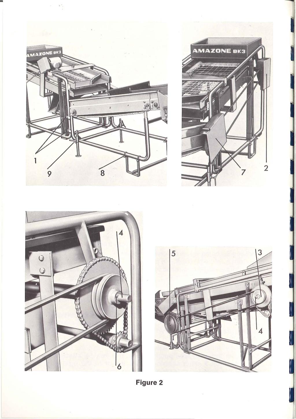
6 D) ATTACHING OF THE SORTING TABLE VK 3 TO THE GRADER BK 3 The AMAZONE potato grader BK 3 has been designed to be the basic machine to which all other accessories offered may be attached consecutively lateron (Fig. 1 a). The AMAZONE BK 3 can be converted into a AMAZONE Fortschritt 111 (Progress 111) by simply attaching the sorting table VK 3 to the grader BK 3 as explained in the following: 1. Remove the sack filling chutes on the lower end of the grader BK 3 (Fig. 1/5). 2. Remove the 4 bolts on the sorting table VK 3 (Fig. 2/1) and bolt the VK 3 to the BK 3 as shown. 3. Remove the protection hood (Fig. 2/2) from the grader BK The supplied double V-Belt pulley (Fig. 2/3) has to be pushed onto the shaft (Fig. 2/4) and aligned with the pulley (Fig. 2/5). Thereafter secure the double V-belt pulley with keys as shown in Fig. 2/ 6 and put on the V-belts. 5. Reinstall the protective hood (Fig. 2/2) which had been taken off before and put on the hood (Fig. 2/7). 6. Installation of the supporting legs: a) Remove the nuts of the supporting legs. b) Lift the machine, push the U-bolts around the tube of the frame (Fig. 2/8) and tighten nuts firmly. c) To give the machine during operation a better standing lower the center support down to the ground by loosening the wing bolts (Fig. 2/9) and by retightening them after the center supports have reached the desired position. Should the machine be equipped with a driving device the center supports have to be lifted and fixed before driving! 5

7 ,._ Figure 3
8 E) GRADING TO 4 SIZES 1. Unbolt filling chute (Fig. 3/ 1) and motor console (Fig. 3/ 2) (if existing). 2. Lay optional riddle box (Fig. 3/3) on to the upper riddle box and fix it with bolts (Fig. 3/4). 3. Should the BK 3 had been equipped with a motor before, the motor console extension has to be bolted underneath the motor console. This together has to be bolted to the frame Fig. 3/5) loosely. Now put on the V-belts (Fig. 3/6) and tighten the V-belts by pulling backward the motor-console in direction of the arrow (Fig. 3/7). Thereafter tighten bolts (Fig. 3/ 5) firmly. 4. The side-outlet for the grading to 4 sizes has to be bolted with the bracket (Fig. 3/8) to the frame of the BK Unbolt the push rod holder (wood) Fig. 3/9 and replace it with the supplied iron counter balance. 6 Take off bolts of the leaf springs (Fig. 3/10) of the upper riddle box_ and instal I the leaf spring reinforcement (Fig. 3/11) horizontally. 7

9 3 2 Figure 4 Figure 5 Figure 5
10 F) INSTALLATION OF SIDE OUTLET FOR OVER SIZES 1. Hang in the outlet for oversizes as shown in Fig. 4/ Bolt loosely the riddle box outlet to the riddle box (Fig. 4/2). 3. Unbolt the potato guide board, place guide board extension with its fixing hole underneath the guide board as shown on Fig. 4/4 and retighten the hinge bolt again. 4. Drill a hole through both the guide board and the guide board extension and bolt them together (Fig. 4/5). 5. Now the bolt (Fig. 4/2) on the riddle box may be tightened firmly. G) INSTALLATION OF OUTLET FOR ROTTEN POTATOES The outlet to select the rotten potatoes by hand can be hooked on to any place of the side of the sorting table. H) INSTALLATION OF THE STEPLESS VARIABLE SPEED TRANSMISSION 1. Remove protection hoods (Fig. 5/1) and (Fig. 5/2). 2. Take off the V-belt (Fig. 5/3) from the grader BK Attach the step less variable speed transmission with the 2 U bolts (Fig. 5/4) to the grader BK Take off protective hood (Fig. 5/5) by loosening the bolt (Fig. 5/6). 5. Put on the supplied V-belts, so that the shorter V-belt (Fig. 5/7) (from the motor to the variable speed transmission) lays between the outer pulley discs (Fig. 5/ 8) and the longer V-belt (Fig. 5/9) (from the flywheel pulley Fig. 5/ 10 to the variable speed transmission) lays between the inner pulley discs (Fig. 5/ 11). 6. Tension the V-belt (Fig. 5/9) by pulling backward the variable speed transmission and fix it with the aid of the U-bolts (Fig. 5/4), tighten the nuts firmly. 7. Tension the V-belt (Fig. 5/7) by pulling backward the motor console. Herefore the bolts (Fig. 5/12) may have to be loosened and retightened again firmly afterwards. 8. The speed of the movement of the potato riddles and sorting table belt can be variated by the setting of the star grip (Fig. 5/13) according to the requirements in direction of the arrows (left = fast - right = slow). 9

11 Figure 6 Figure 7
12 I) INSTALLATION OF THE DRIVING DEVICE WITH KNUCKLE STEERING AND STEEL- OR RUBBER WHEELS 1. Unbolt the U-bolts (Fig. 6/ 1) of the front axle. Pull out the 3 spring pins (Fig. 6/ 2) and remove the track rod (Fig. 6/3). 2. Lift the machine, push front axle underneath and bolt it with the U-bolts (Fig. 6/4) to the frame. 3. Replace the track rod (Fig. 6/5) so it is positioned above the frame tube (Fig. 6/6) and secure it by inserting the spring pins. 4. Hook on the drawbar, fasten it with pin (Fig. 6/7) and secure the latter with the spring pin. 5. Take the rear axle and remove the bolts (Fig. 6/8) of the frame supports (Fig. 6/ 9). 6. Now lift the rear end of the machine and place the rear axle underneath in such a way that the tubular frame (Fig. 6/6) is placed between the support brackets (Fig. 6/9). Thereafter reinsert the bolts (Fig. 6/8) and tighten nuts firmly. 7. When putting the machine into operation lower the center supports as explained under chapter D), position 6. K) TRAVERSAL DRIVING DEVICE (FOR STRAIGHT OR TRAVERSAL DR IVING) 1. Assembly for straight pulling of the machine : Remove the wing bolts (Fig. 7/ 1) and the 3 spring pins (Fig. 7/2). Lift off track rod (Fig. 7/3), raise the machine to push underneath the front axle (Fig. 7/ 4) and fasten the latter to the tubular frame by means of the l.j-bolts. Now place the track rod a q o v e the frame tube (Fi g. 6 / 6) and secure it with the 3 spring pins. 2. Preparing the machine for traversal movement: Loosen the fixing bolt (Fig. 7/5). Remove the 3 spring pins (Fig. 7/2) and lift off the front axle, the track rod (Fig. 7/3). Now swivel all 4 wheels 90 sideways and tighten all 4 fixing bolts (Fig. 7/5 and Fig. 7/6). Attention! Keep the track rod (Fig. 7/3) for changing the machine lateron again for straight driving. 11

13 Tensioning of the sorting belt here 1 Figure 8
14 L) TENSIONING OF THE SORTING BELT Loosen bolts (Fig. 8/1) on both sides. Insert a pin or a screwdriver into the tube (Fig. 8/2) and turn the tensioning disc clockwi se (this way the tensioning belt will be tensioned). If the desired tensioning has been achieved hold the tensioning disc with the screw driver in the desired position and tighten the bolts (Fig. 8/1) again firmly. Please watch that both sides are tensioned by the same amount, otherwise the belt might travel to one side. Should the belt travel to one side always tension it on that side toward which the belt was moving. M) REPLACEMENT OF THE SORTING BELT 1. Let the sorting belt run so far that the connecting hinge is centrally positioned under~ ath the sorting table. 2. Detension the sorting belt entirely. 3. Remove the belts hinge pins and pull out the old sorting belt. Now insert the new belt again, so that the connecting points will again be underneath the sorting table. Insert pins again. 4. Tension sorting belt as described under chapter L). 13

15 Figure 9
16 N) FEEDING BELT Fix upper support (Fig. 9/ 1) of the feeding belt to the tubular frame of the BK Take off protective hood (Fig. 9/2) from the grader BK Align the V-belt pulley of the feeding belt with the double V-belt pulley of the grader BK 3 (Fig. 9/3). Now tighten the fixing bolt of the feeding belts V-belt pulley firmly. 4. Put on V-belt. This V-belt will be tensioned by pulling upward the feeding belts supports (Fig. 9/4). 5. Replace protective hood (Fig. 9/2), secure it with spring pins and bolt on protective hood (Fig. 9/5). 6. Put on the supplied support bars (Fig. 9/6) with their fork-like end onto the traversal member (Fig. 9/7) of the BK 3 and secure it with spring pin. 7. Bolt the guide (Fig. 9/8) to the feeding belt. 8. The filling height of the feeding belt can be adjusted by lifting the feeding belt ZB 22 and fixing it in the desired position by tightening the lever bolt (Fig. 9/9). 9. Retensioning of the feeding belts will be done at the tensioning bolts (Fig. 9/10). Should the belt run to one side the tensioning has to be increased on that side to which the belt is run ning. 10. The replacement of the feeding belt will be done in the same manner as described under chapter M). 15

17 Figure
18 0 ) FEEDIN G BELT ZBS 22, 180 SWIVELLIN G 1. Remove the 4 bolts (Fig. 10/ 1) of the input box of the grader BK Take the swivel rail tube (Fig. 10/2) and put the 4 bolts (Fig. 10/1 ), which had been taken off before, through the guide rail tubes supports (Fig. 10/3) and tighten them again. 3. The swivelling feeding belt (Fig. 10/5) will be put in such a manner onto the swivel guide rail tube (Fig. 10/ 4) that from the side the rollers (Fig. 10/6) will be pushed over the swivel rail tube (Fig. 10/4). 4. Install motor console with motor (Fig. 10/7). 5. Put the smaller supplied V-belt pulley onto the swivelling feeding belts input shaft (Fig. 10/8), align it with the motors V-belt pulley (Fig. 10/ 9) and secure both pulleys with the supplied keys (Fig. 10/10). 6. Put on V-belt and tension it by pulling downward the motor console (Fig. 10/7) and fix it in the desired position. 7. Put on protective hood (Fig. 10/12) and secure it with spring pins. 8. Attach the swivelling feeding belts chute to the side members (Fig. 10/13) with bolts. 9. For transportation the supplied supports have to be fixed to the machine according to Fig. 10/ The tensioning of the belt is done at the tensioning bolts (Fig. 10/15). Should the belt be running to one side always tension the belt on that side to which the belt is travelling. 11. Replacement of the belt will be done in the same manner as described under chapter M). P) CATCHING LEDGES FOR FEEDING BELT ZB 22 AND ZBS 22 The feeding quantity of the feeding belts can be increased or reduced by simply attaching or removing some catching ledges (conveying boards) to or from the belt. The catching ledges are fixed to the belts with a toggle, which is reaching through the slits of the belts and twisted 90 on the rear side of the belt. If some catching ledges have to be removed just twist the toggles 90 and pull them off. When inserting catching ledges please watch that the supports (Fig. 10/16) are showing opposite to the moving direction of the feeding belt (showing downward). 17

19 Figure 11
20 Q} LOADING BELT LB Connect the loading belts carrying beam (Fig. 11/2) with the aid of the clamps (Fig. 11 / 1) to the sorting table. 2. Bolt together the two chain carriers (Fig. 11/3). 3. Hang the loading belt LB 20 into the carriers (Fig. 11/4) and secure it with bolts (Fig. 11/5). 4. Connect chain (Fig. 11/6) and the cable (Fig. 11/7) with the chain carriers (Fig. 11 /3). The other end of the chain (Fig. 11 /6) has to be fixed to the hook on the motor console. 5. The loading belt is height-adjustable. For changing the height pull out the securing pin (Fig. 11/8), turn the crank (Fig. 11/9) until the loading belt has the desired position. Thereafter insert the securing pin again. 6. Attach the chute (Fig. 11 /10) and the bounce reducing curtain to the outlet (Fig. 11/11 ). 7. Re_move protective hood (Fig. 11/12 and 11 /12a, 11/12b) from the sorting table. 19

21 Figure 11 21
22 8. Remove V-belts (Fig. 11/13) and single V-belt pulley. 9. Put on double V-belt pulley (Fig. 11 /14) and align it with the driving V-belt pulley (Fig. 11 /15) at the grader BK 3, secure it with keys and put on V-belt (Fig. 11/13) again. 10. Put on shaft extension (Fig. 11 /16) onto the loading belts drive shaft and tighten bolts. 11. Put on the sup pi ied V-belt pulley (Fig. 11 /17) onto the drive shaft extension, align it with the double V-belt pulley (Fig. 11/14) and secure it with keys. 12. Put on V-belts (Fig.11 /18). 13. Install the supplied belt tensioners according to Fig. 11 / Reinstall protective hoods (Fig. 11 /12, 11 /12a, 11 /12b) onto the sorting table and secure them with spring pins. The protective box of the loading belt has to be put onto the Li-support and to be bolted (Fig. 11 / 20). 15. The adjustment of the angle of the loading belt chute is done at the hole plate (Fig. 11/21 ). 16. The tensioning of the loading belt will be done at the tensioning bolts (Fig. 11/22). If the loading belt is running to one side, always tension it on that side to which it is running. 17. Replacement of the belt will be done in the same manner as described under chapter M). 21

23 Figure 12
24 R) LOAD ING BELT LBS 20, 180 SWIVELLING 1. Bolt the turning racer (Fig. 12/2) to one of the two loading belt carriers (Fig. 12/ 1 ). 2. Now bolt the loading belt carrier to the frame of the sorting table as shown in Fig. 12/3. 3. Now bolt also the other loading belt carrier to the frame of the sorting table and to the turning racer. The two loading belt carriers have to be bolted together with the chain fixing plate (Fig. 1 2/ 4). 4. Now insert the loading belt LBS 20 into the retainers (Fig. 12/5). 5. Hang in the chain (Fig. 12/6) and the cable (Fig. 12/7) into the chain fixing plate (Fig. 12/4). The other end of the chain (Fig. 12/6) has to be fixed to the hook of the motor console. 6. The swivelling loading belt is also height adjustable. To adjust the height pull out securing pin (Fig. 12/8) and turn crank (Fig. 12/9) until the swivelling loading belt has reached the required position. Now fix crank again with the securing pin! 7. Put on V-belt (Fig. 12/10) and protective hood and secure the latter with spring pins. 8. The tensioning of the V-belt (Fig. 12/10) may be obtained by equal turning of all nuts of the motor fixing flange (Fig. 12/11 ). 9. The retensioning of the LBS 20 belt may be done at the tensioning bolts (Fig. 12/12). If the belt is running to one side always tension the belt on that side to which the belt is running. 10. The angling of the chute may be adjusted with the hole plate (Fig. 12/ 13) to any position required. 11. Replacement of the loading belt may be done in the same manner as described under chapter M). 23
")
25 Position of grease nipples (see page 25) Figure 13
26 S) MAINTENANCE Clean the machine and its accessories after every use and grease it with a good lubricant. Figure 13 Position without illustration Description of Part Number of grease nipples Counter shaft 2 Crankshaft-end bearings (only in execution with plain bearings) 2 Driveshaft, sorting table 2 Turning shaft of sorting table 2 V-belt tensioner 1 Turning shaft, feeding-belt 2 Turning shaft, loading-belt 2 V-belt tensioner 1 Steering knuckle 2 Steering knuckle f. traversal driving device 4 Stepless variable transmission 1 Oil Stepless variable transmission a little 1 hole I I I I T) GENERAL HINTS 1. Keep hands off running and moving parts! (Danger of injury!) 2. Store machine after use under a roof! 3. Order genuine AMAZONE spare parts, ask for spare parts book. 4. Check periodically all bolts and nuts for tightness. 5. The graders AMAZONE BK 3 and AMAZONE Fortschritt Ill may be used for grading and sorting also other crops, like carr,ots, onions, beets, beans etc. 25
Copyright 2001 by AMAZONEN-Werke H. Dreyer GmbH & Co. KG D Hasbergen-Gaste All rights reserved
 Instruction Manual AMAZONE Bulk Precision Broadcaster ZG-B 6001, ZG-B 7001, ZG-B 10001 ZG-B 8001 R, ZG-B 12001 R, ZG-B 16001 TR MG 251 DB 510-2 GB 09.01 Printed in Germany Before starting to operate, please
ASSEMBLY INSTRUCTIONS FOR CHARGER AND THE BOSS QUICK ATTACH GRASS BAGGER
 ASSEMBLY INSTRUCTIONS FOR CHARGER AND THE BOSS QUICK ATTACH GRASS BAGGER \ \ \ \ ~\ P P-12102 (7/2005) TABLE OF CONTENTS SECTION PAGE WARNING 1 BLOWER PULLEY INSTALLATION 2 ENGINE GUARD REMOVAL BOSS 3
SPARES LIST. Cippo 15 RV-0204
 SPARES LIST Cippo 15 RV-0204 INDEX TAV. 1 Basic Machine TAV. 2 Petrol Transmission HP 20 TAV. 3 TAV. 4 TAV. 5 TAV. 6 TAV. 7 4 wheels trailer Road trailer 80 Km/h Hydraulic System Diesel Transmission HP
ROWEKO LOAD-SECURING EQUIPMENT
 84 www.roweko.de Transportation tube for roof rack How long do you need to securely tie tubes or similar long goods onto your roof rack? How certain are you that you don t lose anything during your journey
MORRISON MS-40C MATERIAL SPREADER
 INSTRUCTION MANUAL & PARTS BOOK MORRISON MS-40C MATERIAL SPREADER POWERFUL - EFFICIENT - DEPENDABLE 25 INDUSTRIAL DRIVE, KEYPORT, NEW JERSEY, USA, 07735, 732-566-5400 FAX 732-5444 Doc. # OI M09203 PB M09203
OLYMPIAN MODEL 740 Operation and Service Manual
 OLYMPIAN MODEL 740 Operation and Service Manual P/N 133911-102 FCI MANUAL P/N 133865-001 Data herein has been verified and validated and believed adequate for the intended use. If the machine or procedures
CALIFORNIA TRIMMER MOWER MAINTENANCE MANUAL
 CALIFORNIA TRIMMER MOWER MAINTENANCE MANUAL 2 Table of Contents Section 1: General Information Page Handle Assembly Instructions 4 Maintenance All Models 6 Oil Change Procedures All Models 9 Height Adjustment
Installation instructions
 Service Installation instructions Audi A3 (8V3) 2012 Roof bars 8V3.071.126 for vehicles with bright moulding package (PR no. 4ZB) and roof bars 8V3.071.126.L for vehicles with black moulding package (PR
GASENGINES V2 CLASSIC ASSEMBLY PLAN
 GASENGINES V2 CLASSIC ASSEMBLY PLAN 1 ASSEMBLY PLAN Component parts are to some extent fitted together as subassemblies. 1. Mounting the crankshaft bearing 1.1 Fit the short crankshaft with both bearings
Dynamic Probing / Window Sampling Rig with folding mast on rubber chain crawler GTR790
 Dynamic Probing / Window Sampling Rig with folding mast on rubber chain crawler GTR790 Contents: 1. Description 2. Safety Instructions 3. Pre-Start CHECK-LIST 4. Driving/tracking the GTR790 5. Dynamic
Repair Manual 11/99 PS-34. Page 1
 Repair Manual /99 PS-4 Page Table of contents Index Technical Data page Special tools 4 Repair instructions, general 0 Chain brake 6 0 Centrifugal clutch 8 0 Oil pump 9-04 Ignition system - 0 Starting
1967 (Late) CORVETTE STANDARD (NON-ADJUSTABLE) STEERING COLUMN DISASSEMBLY & REPAIR INSTRUCTIONS PAPER #2
 CORVETTE STANDARD (NON-ADJUSTABLE) STEERING COLUMN DISASSEMBLY & REPAIR INSTRUCTIONS PAPER #2") Last Revision: 03SE2012 1967 (Late) - 1968 CORVETTE STANDARD (NON-ADJUSTABLE) STEERING COLUMN DISASSEMBLY & REPAIR INSTRUCTIONS PAPER #2 Disassembly and Repair Instructions Addressed in this Paper Degree
Last Revision: 03SE2012 1967 (Late) - 1968 CORVETTE STANDARD (NON-ADJUSTABLE) STEERING COLUMN DISASSEMBLY & REPAIR INSTRUCTIONS PAPER #2 Disassembly and Repair Instructions Addressed in this Paper Degree
WEDICO. aêçé=aéåâ=péãájqê~áäéê= Art.-No. 21 yellow
 WEDICO Art.-No. 1 yellow ^ÅÅÉëëçêáÉë=EçéíáçåëFW= Electronic Speed Controller...Art.-No. 95 Winch for Drop Deck Semi-Trailer...Art.-No. 44 Electrical System...Art.-No. 784 Electrical System MF-A...Art.-No.
ASSEMBLY MANUAL. 45-Foot Air Double Disc Drill. Amity Technology, LLC th Avenue North Fargo, ND (701)
") ASSEMBLY MANUAL 45-Foot Air Double Disc Drill Amity Technology, LLC 2800 7th Avenue North Fargo, ND 58102 (701) 232-4199 www.amitytech.com TABLE OF CONTENTS Main Frame 1 Wing Lock Towers 3 Wing Frames
ASSEMBLY MANUAL 45-Foot Air Double Disc Drill Amity Technology, LLC 2800 7th Avenue North Fargo, ND 58102 (701) 232-4199 www.amitytech.com TABLE OF CONTENTS Main Frame 1 Wing Lock Towers 3 Wing Frames
Property of American Airlines
 Date Maintenance Check list This document describes the inspection and maintenance of the Power Stow Rollertrack. Maintenance refers to a time span. The operation hours are shown on the Power Stow Display
Sisu S-Cam Drum Brakes
 Sisu S-Cam Drum Brakes (For hub reduction rear axles since 1992) Maintenance Manual Sisu Axles, Inc. Autotehtaantie 1 P.O. Box 189 FIN-13101 Hämeenlinna Finland Phone int + 358 204 55 2999 Fax int + 358
SCdefault. 900 Installation instructions
 SCdefault 900 Installation instructions SITdefault Sports chassis MONTERINGSANVISNING INSTALLATION INSTRUCTIONS MONTAGEANLEITUNG INSTRUCTIONS DE MONTAGE Accessories Part No. Group Date Instruction Part
Removing/installing final drive
 1(16) Removing/installing final drive Special tools: 998 5972, 999 5561, 999 5652, 999 5659, 999 5660 Removing Note! Position the rear lifting arms on the arrows on the sills. This is so the support arm
Clutch Installation Guide
 Clutch Installation Guide 0 STOP! READ CAREFULLY BEFORE INSTALLING CLUTCH This clutch must be installed by a qualified installer. Improper installation or failure to replace or resurface the flywheel,
2000SR. Installation Instructions May Donovan Enterprises 3353 S.E. Gran Park Way Stuart, Florida
 311499-Donovan 4/28/04 11:22 PM Page 1 Installation Instructions May 2003 Donovan Enterprises 3353 S.E. Gran Park Way Stuart, Florida 34997 1-800-327-8287 Visit our web site at: www.donovan-ent.com 311499-Donovan
AmTryke Adult Recumbent Model JT2000 #50-FC-2000
 AmTryke Adult Recumbent Model JT2000 #50-FC-2000 TOOLS Needed for Assembly 5 mm Allen Wrench 8 mm Socket or Wrench 10 mm Socket or Wrench 14 mm Socket or Wrench 15 mm Socket or Wrench 22 mm Socket or Adjustable
Your G3 buggy is fitted with three switches on the front part of the body:
 CONTENTS Buggy operation... 3 General Maintenance... 5 Technical Maintenance... 6 Front wheel bearing replacement... 6 Rear wheel bearing replacement... 7 Chain replacement... 8 Chain Adjustment... 9 Brake
3 Axles and brakes. 3.1 Function and construction of the axles Construction Function
 3 Axles and brakes 3.1 Function and construction of the axles 3.1.1 Function Each wheel has an independent suspension system in the axle body (1), so that individual wheel suspension is provided. The swinging
DM-TRSL (English) Dealer's Manual. ROAD MTB Trekking. City Touring/ Comfort Bike. Shifting lever DEORE XT SL-T8000 DEORE SL-T6000
 Dealer's Manual. ROAD MTB Trekking. City Touring/ Comfort Bike. Shifting lever DEORE XT SL-T8000 DEORE SL-T6000") (English) DM-TRSL001-01 Dealer's Manual ROAD MTB Trekking City Touring/ Comfort Bike URBAN SPORT E-BIKE Shifting lever DEORE XT SL-T8000 DEORE SL-T6000 CONTENTS IMPORTANT NOTICE... 3 TO ENSURE SAFETY...
(English) DM-TRSL001-01 Dealer's Manual ROAD MTB Trekking City Touring/ Comfort Bike URBAN SPORT E-BIKE Shifting lever DEORE XT SL-T8000 DEORE SL-T6000 CONTENTS IMPORTANT NOTICE... 3 TO ENSURE SAFETY...
Installation & Operation Manual
 Installation & Operation Manual Thank you for purchasing our AS4795.1 Butterfly Valve. Before installing or operating, please carefully read this manual to know thoroughly how to install or operate. The
VR482 Hay Rake OPERATOR & PARTS MANUAL. Last Updated: May 12, 2014
 VR482 Hay Rake OPERATOR & PARTS MANUAL Last Updated: May 12, 2014 Bridgeview Manufacturing Inc. P.O. Box 4 Gerald, SK S0A 1B0 (306) 745-2711 www.bridgeviewmanufacturing.com bmi@sasktel.net Your Authorized
Airbags, servicing. Airbag system, safety precautions WARNING!
 Page 1 of 75 69-40 Airbags, servicing Airbag system, safety precautions Checking, removing, installing and servicing may ONLY be performed by qualified personnel. Never perform tests using a test light
2006 MINI Cooper SUSPENSION Wheels & Tires - Repair Instructions - Cooper (1.6L) R50/W10 & Cooper S
 R50/W10 & Cooper S") WHEELS 2002-05 SUSPENSION Wheels & Tires - Repair Instructions - Cooper (1.6L) R50/W10 & Cooper S 36 10 300 REMOVING OR INSTALLING FRONT OR REAR WHEEL NOTE: For Special Tool identification, see WHEEL AND
WHEELS 2002-05 SUSPENSION Wheels & Tires - Repair Instructions - Cooper (1.6L) R50/W10 & Cooper S 36 10 300 REMOVING OR INSTALLING FRONT OR REAR WHEEL NOTE: For Special Tool identification, see WHEEL AND
1. Set the position of the hub to FREE and remove the six hex-drive bolts.
 1. Raise vehicle on a hoist, remove road wheels, disconnect the drag-link from the passenger-side hub assembly and disconnect the steering tie rod ends from both the driver and passenger side hub assemblies.
AmTryke Adult Recumbent Model HP1000 #50-HC-1000
 AmTryke Adult Recumbent Model HP1000 #50-HC-1000 TOOLS Needed for Assembly 5 mm Allen Wrench 8 mm Socket or Wrench 10 mm Socket or Wrench 14 mm Socket or Wrench 15 mm Socket or Wrench 22 mm Socket or Adjustable
Installation and Operation Manual. Manufacturers of Innovative Materials Handling Equipment since 1957.
 SWINGSET DISTRIBUTOR Installation and Operation Manual Manufacturers of Innovative Materials Handling Equipment since 1957. 491 North Emerson Street * Cambridge MN 55008-1316 U.S.A. Toll Free (800) 328-8002
Front seats. j a t CAUTION! Before beginning repairs on the electrical system: Obtain the anti-theft radio security code. Switch the ignition off.
 j a t Front seats 72-1 CAUTION! Before beginning repairs on the electrical system: Obtain the anti-theft radio security code. Switch the ignition off. Search Advanced Search Disconnect the battery Ground
ACROBAT SWING STAND MODEL
 Mounting instructions Directions for use ACROBAT SWING STAND MODEL Dr. Mach GmbH u. Co.KG, Flossmannstrasse 28, D-85560 Ebersberg Tel.: +49 (0)8092 2093 0, Fax +49 (0)8092 2093 50 Internet: www.dr-mach.com,
STIGA PARK 4 WD 107 M 107 M HD 121 M. 125 Combi Pro B INSTRUCTIONS FOR USE. »HC P K»fl œoà «Œ EÀfl
 STIGA PARK 4 WD 107 M 107 M HD 121 M 125 Combi Pro B INSTRUCTIONS FOR USE»HC P K»fl œoà «Œ EÀfl 8211-0543-01 1 125 Combi Pro 2 125 Combi Pro 3 125 Combi Pro 121 M 107 M HD A B C B 4 125 Combi Pro 107 M
HT-Shaver FB Harvester User Manual
 HT-Shaver FB Harvester User Manual REID LINE EAST, RD 5 FEILDING 4775, New Zealand Phone (06)323 2509 Fax (06)323 2709 Email info@harvesterconcepts.co.nz 9/2012 Jenquip 2010 Freighting Freighting on the
High-Rise Tire Dolly
 High-Rise Tire Dolly Assembly & Operation Instructions Model 70131 Capacity 1000 lb SAVE THESE INSTRUCTIONS. For your safety and the safety of others around you, read carefully before attempting to install,
Marcy Diamond Home Gym
 NOTE: Please read all instructions carefully before using this product Table of Contents Safety Notice Hardware Identifier Assembly Instruction Marcy Diamond Home Gym MD-2109 Parts List Resistance Chart
Perfect Park 7000 Installation & Unloading Instructions Operating Manual
 Perfect Park 7000 Installation & Unloading Instructions Operating Manual 1) Always file a claim with the truck line if the lift has been damaged! (If you don t originally notice the damage, but find some
INSTRUCTION MANUAL FOR ESP GROSS BAGGING SCALE MODEL GB-17, GB-25, GB-32, GBAO-21, GBAO-25, GBAO-31 & GBAO-37
 INSTRUCTION MANUAL FOR ESP GROSS BAGGING SCALE MODEL GB-17, GB-25, GB-32, GBAO-21, GBAO-25, GBAO-31 & GBAO-37 The Don Marshall Company, Inc. PO Box 124, 235 Maple St., Plain City, OH 43064 614-873-8520,
62 Deck Idler Kit High Speed
 Part No. 00 FORM NO. -899 6 Deck Idler Kit High Speed For Model 70 Serial No. 99000 to 99000 For Model 7 Serial No. 9900 to 99000 INSTALLATION INSTRUCTIONS Loose Parts Note: Use the chart below to identify
SX1000 Service Manual SALES: CUSTOMER SERVICE:
 SX1000 Service Manual SALES: 800-278-3933 CUSTOMER SERVICE: 800-745-1373 Revision: August 1999 Table of Contents Section Page I. Overview 2 II. Troubleshooting Tables 3 III. Maintenance Procedures Procedure
INSTALLATION & OWNER S MANUAL
 Rev. C, p. of 2 INSTALLATION & OWNER S MANUAL KUBOTA B2650/3350 Hard Sided Cab p/n KB33AS Soft Sided Cab p/n KB33SS Installation Instructions The contents of this envelope are the property of the owner.
GPS AutoSteer System Installation Manual
 GPS AutoSteer System Installation Manual Supported Vehicles Case IH Vehicles Case 2577 Combines Case 2588 Combines Accuguide Ready PN: 602-0233-01-A LEGAL DISCLAIMER Note: Read and follow ALL instructions
E L L I O T T 14M, 18M & 24M. Contents OPERATORS INSTRUCTION HANDBOOK FOR THE HIGH SPEED SHAPING MACHINES MODELS. Also COMPONENT PARTS LIST.
 OPERATORS INSTRUCTION HANDBOOK FOR THE E L L I O T T HIGH SPEED SHAPING MACHINES MODELS 14M, 18M & 24M Also COMPONENT PARTS LIST Contents Page Slinging 2 Examination 2 Cleaning 2 Installation 3 Foundation
PEARL DRUM PEDAL. Instruction Manual
 PEARL DRUM PEDAL Instruction Manual Congratulations on your purchase! To get optimum performance of your "P-2050C / P-2050B" Drum Pedal, please read this Instruction Manual before playing. (for Footboard
Self-Adjust Clutch Installation Guide
 Self-Adjust Clutch Installation Guide 0 STOP! READ CAREFULLY BEFORE INSTALLING CLUTCH This clutch must be installed by a qualified installer. Improper installation or failure to replace or resurface the
Instruction Manual UK
 Instruction Manual UK Product: Monterey2 child booster seat Model: 15000 Mfg. by: DIONO Unit D Ventura House Ventura Park Road Tamworth Staffs B78 3LZ UK CUSTOMER SERVICE Tel: 0845.300.9071 Email: dionouk@diono.com
Installation Instructions
 Preparing your vehicle to install your brake system upgrade 1. Rack the vehicle. 2. If you don t have a rack, then you must take extra safety precautions. 3. Choose a firmly packed and level ground to
Mitsubishi Lancer Oil Change (2.0L I4 DOHC)
") 2002-2007 Mitsubishi Lancer Oil Change (2.0L I4 DOHC) Change the oil in your '02-'07 Mitsubishi Lancer, with 2.0L I4 DOHC engine, to improve engine performance and longevity. Written By: Phillip Takahashi
2002-2007 Mitsubishi Lancer Oil Change (2.0L I4 DOHC) Change the oil in your '02-'07 Mitsubishi Lancer, with 2.0L I4 DOHC engine, to improve engine performance and longevity. Written By: Phillip Takahashi
Property of American Airlines
 Date Maintenance Check list The inspection and preventive maintenance schedule of the Power Stow Rollertrack is as follows: Daily (10 hrs), Weekly (50 hrs.), every 6 months ( hrs.), yearly (1 hrs.) and
MAINTENANCE INSTRUCTIONS
 MAINTENANCE INSTRUCTIONS ECOMAT EASY / GIROTEC WRS Version G0101 ECOMAT EASY H / GIROTEC WRS H Version G0301 ECOMAT PLUS / ECOMAT PLUS H Versions G0503 / G0603 V 2.0 Table of contents 1/3 1.0 Maintenance
1. Set the position of the hub to FREE and remove the six hex-drive bolts.
 1. Raise vehicle on a hoist, remove road wheels, disconnect the drag-link from the passenger-side hub assembly and disconnect the steering tie rod ends from both the driver and passenger side hub assemblies.
IRON GRIP STRENGTH SMITH MACHINE
 NOTE: Please read all instructions carefully before using this product Table of Contents Safety Notice Hardware Identifier Assembly Instruction IRON GRIP STRENGTH SMITH MACHINE IGS-4350 Parts List Warranty
Operating instructions ErgoPack 600 E
 Operating instructions ErgoPack 600 E Operation of the device is only permitted if the operating instructions have been carefully read and understood before use! Declaration of conformity EU declaration
Operating instructions Assembly instructions
 MOBILITY MADE SIMPLE! Adapter & Adaptation Operating Instructions Operating instructions Assembly instructions Adapter & adaptation for NJ1 e-assistant, NJ1 adaptive bike, SPIKE adaptive bike and FREEWAY
KONGSKILDE Vertical Tillage - Assembly Guide ASSEMBLY INSTRUCTIONS Revision 18 Serial No current Series.
 KONGSKILDE 9100 Vertical Tillage - Assembly Guide Kongskilde 9100 Series *Model may not be exactly as shown. Kongskilde reserves the right to make changes to product designs and specifications without
DODGE SuperRail Mounting Kit #0848
 DODGE SuperRail Mounting Kit #0848 #1200 Super 5 th (16K) #0800 Super 5 th (20.5K) Gross Trailer Weight (Maximum) Vertical Load Weight (Max. Pin Weight) 16,000 lbs. 4,000 lbs. Gross Trailer Weight (Maximum)
T E R R A X Instruction Manual
 Instruction Manual TERRA X Contents Introduction.................. 3 Product description............. 4 Explanation of symbols........... 4 Safety Precautions............... 5 General safety instructions.........
A1062 & A1072 AUGER ASSEMBLY MANUAL. Read & understand all instructions pertaining to this auger prior to use!
 A1062 & A1072 AUGER ASSEMBLY MANUAL Read & understand all instructions pertaining to this auger prior to use! Safety Alert Watch for this ALERT Symbol. It identifies potential hazards to Personal SAFETY
Support legs. Installation and operating instructions
 Support legs Installation and operating instructions Table of contents 1 Explanation of symbols... 3 2 Assembly... 4 3 Operation... 5 4 Servicing and testing... 8 2 MUB 013 001 M01 (REV--) 11/2016 Support
SECTION 17 SUSPENSION CONTENTS FRONT SUSPENSION REAR SUSPENSION MAINTENANCE SERVICES
 SECTION 17 SUSPENSION CONTENTS 17-1. FRONT SUSPENSION...................................... 17-2 17-2. REAR SUSPENSION...................................... 17-15 17-3. MAINTENANCE SERVICES................................
ProPass-200 Top Dresser
 Setup Manual Form No. 3365-184 Rev A ProPass-200 Top Dresser Model No. 44700-Serial No. 310000001 and Up Model No. 44701-Serial No. 310000001 and Up Model No. 44704 Model No. 44705 Model No. 44706 Model
GWM GROSS WEIGH BAGGING SCALE
 GWM GROSS WEIGH BAGGING SCALE The GWM Gross Weigh Mechanical Bagging Scale is designed for handling 20 lb. (10 kg.) through 110 lb. (50 kg.) weighments at a rate of 5-6 bags per minute and with an accuracy
Rear seat. Rear seat, removing and installing. - Using screwdriver -2-, carefully lift headrest guides -3- out of rear backrest -1-.
 Page 1 of 19 72-57 Rear seat Rear seat, removing and installing - Using screwdriver -2-, carefully lift headrest guides -3- out of rear backrest -1-. - Detach rear seat -2- upward out of mounting -3-.
Sealing flanges and flywheel/drive plate, removing and installing
 Page 1 of 20 13-47 Sealing flanges and flywheel/drive plate, removing and installing Note: For repairs to the clutch: Repair Manual, 5 Spd. Manual Transmission 012/01W Front Wheel Drive, Repair Group 30
HAND THROTTLE KIT For Workman 3000 Series
 FORM NO. 7 6 MODEL NO. 0746 INSTALLATION INSTRUCTIONS HAND THROTTLE KIT For Workman 000 Series. Position vehicle on a clean, level surface, stop engine, engage parking brake and remove key from ignition
Honda Civic Oil Change
 1988-1991 Honda Civic Oil Change Change the oil in your '88-'91 Honda Civic to improve engine performance and longevity. Written By: Phillip Takahashi ifixit CC BY-NC-SA www.ifixit.com Page 1 of 13 INTRODUCTION
It don t mean a thing If it ain t got the swing
 SWING CHUTE SAND/SALT SPREADER INSTALLATION AND OPERATING INSTRUCTIONS SWING CHUTE SPREADER MODELS: 7, 8, 9, 9.5 & 10 MANUAL FOR SPREADER SERIAL NUMBERS AFTER # 20000 It don t mean a thing If it ain t
R25 Recumbent Bike ASSEMBLY & PARTS MANUAL
 R25 Recumbent Bike ASSEMBLY & PARTS MANUAL MA902 Recreation Supply Inc. Model No. R25.1 P.O. BOX 181 BODYCRAFT is a division of Recreation Supply Sunbury, OH 43074 www.bodycraft.com 800-990-5556 info@bodycraft.com
Clutch, servicing. Special tools, testers and auxiliary items required. Flywheel retainer Thrust pad 3062
 Page 1 of 10 30-36 Clutch, servicing Special tools, testers and auxiliary items required Flywheel retainer 10-201 Thrust pad 3062 Page 2 of 10 30-37 Centering mandrel 3176 Grease G 000 100 Notes: Observe
BS 2/K Transverse Conveyor
 Modular Transfer Systems BS 2/K Transverse Conveyor for TSplus Conveyors Installation and Maintenance Guide Publication Number: 8981 500 207 11/00 2 Table of Contents INTRODUCTION... 3 TECHNICAL DATA...
Saab 9-3 CV M04-, 4D/5D M06-
 SCdefault 900 Installation instructions SITdefault MONTERINGSANVISNING INSTALLATION INSTRUCTIONS MONTAGEANLEITUNG INSTRUCTIONS DE MONTAGE Sports chassis Accessories Part No. Group Date Instruction Part
Rear Bumper Cover Unpainted ( ):
:") Rear Bumper Cover Unpainted (1999-2004): Tools Required: Ratchet Socket extension 7/16 deep well socket 7/16 wrench 5/16 socket Fastener Removal Tool Offset Phillips screwdriver Extendable magnet (optional
Rear Bumper Cover Unpainted (1999-2004): Tools Required: Ratchet Socket extension 7/16 deep well socket 7/16 wrench 5/16 socket Fastener Removal Tool Offset Phillips screwdriver Extendable magnet (optional
WEDICO. `çãéäéíé=háí= `çåí~áåéê=péãájqê~áäéê= Art.-No. 64 white
 WEDICO `çãéäéíé=háí= Art.-No. 6 white Measurements Chassis and superstructure Finish Assembly Length...78 mm Width...65 mm Height...58 mm Weight...7 kg Frame made of aluminium section, mm thick; torsion
9/24/2017 Camshaft Timing Chain Removal and Installation Engine Mechanical 2002 Audi A6/S6/Quattro/Allroad MotoLogic
 2002 A6/S6/Quattro/Allroad The information in this article comes from a service manual containing information that applies to the following engine code: BAS. Section Info: Report a problem with this article
Installation Instructions Jeep CJ-7
 Retrofit Steering Column Installation Instructions 1976-86 Jeep CJ-7 For Part # s 1520800010, 152800020, 1520800051 www.ididitinc.com 610 S. Maumee St., Tecumseh, MI 49286 (517) 424-0577 (517) 424-7293
MARCY PLATINUM MP-3500 HOME GYM
 NOTE: Please read all instructions carefully before using this product Table of Contents Safety Notice Hardware Identifier MARCY PLATINUM MP-3500 HOME GYM Assembly Instruction Parts List Warranty Ordering
WEDICO. `çãéäéíé=háí= q~êéjqçé=péãájqê~áäéê= Art.-No. 63
 WEDICO `çãéäéíé=háí= q~êéjqçé=péãájqê~áäéê= Art.-No. 6 Measurements Chassis and superstructure Finish Assembly Length...768 mm Width...7 mm Height...65 mm Weight...8 kg Frame made of aluminium section,
Installation Instructions
 FORD #3100 SuperRail Mounting Kit #3123 Gross Trailer Weight (Maximum)...12,000 lbs. Vertical Load Weight (Max. Pin Weight)...3,000 lbs. Installation Instructions SPECIFICATIONS Fits 2015-2018 Ford F-150
D8 - Distributor. D9 - Auxiliary unit belts
 D8 - Distributor l ubricate Lubricate the distributor shaft sparingly (1-2 drops of oil) D9 - Auxiliary unit belts check/adjust Applies to engines which do not have multi-tooth belts Check belt tension.
INSTALLATION, MAINTENANCE, & SAFETY INSTRUCTIONS
 Tarpaulin Systems Flip -N- Go / Quick Mount Flip -N- Go System INSTALLATION, MAINTENANCE, & SAFETY INSTRUCTIONS (800) CRAMARO (800) 272-6276 Plants In: Delaware, Florida, Massachusetts, Nevada, Ohio Install
Service Bulletin Brake Disc Refinishing Guidelines (Supersedes , dated June 2, 2003) October 28, 2003
 October 28, 2003") Service Bulletin 00-037 Applies To: ALL Models October 28, 2003 Brake Disc Refinishing Guidelines (Supersedes 00-037, dated June 2, 2003) American Honda does not allow replacement of brake discs under
Service Bulletin 00-037 Applies To: ALL Models October 28, 2003 Brake Disc Refinishing Guidelines (Supersedes 00-037, dated June 2, 2003) American Honda does not allow replacement of brake discs under
DM-ST (English) Dealer's Manual. Dual control lever ST-9001 ST-9000 ST-6800 ST-5800 ST-4700 ST-4703
 Dealer's Manual. Dual control lever ST-9001 ST-9000 ST-6800 ST-5800 ST-4700 ST-4703") (English) DM-ST0002-05 Dealer's Manual Dual control lever ST-9001 ST-9000 ST-6800 ST-5800 ST-4700 ST-4703 CONTENTS IMPORTANT NOTICE... 3 TO ENSURE SAFETY... 4 INSTALLATION... 6 List of tools to be used...6
(English) DM-ST0002-05 Dealer's Manual Dual control lever ST-9001 ST-9000 ST-6800 ST-5800 ST-4700 ST-4703 CONTENTS IMPORTANT NOTICE... 3 TO ENSURE SAFETY... 4 INSTALLATION... 6 List of tools to be used...6
Installation instructions, accessories - Rear Seat Entertainment
 XC90 Section Group Weight(Kg/Pounds) Year Month 3 39 2004 10 XC90 2003, XC90 2004, XC90 2005, XC90 2006, XC90 2007, XC90 2008 Replaces issue: 2003 12 J3904620 Page 1 of 18 Required tools A0000162 A0000163
Contents. Sliding Door Gear Product information 155. Roller-Guided Sliding Door Gear. Page
 GEZE APOLL Contents Page Sliding Door Gear Product information 155 Roller-Guided Sliding Door Gear APOLL/Sliding doors 1-55 APOLL/Components 6-17 APOLL/End-folding doors 18-25 APOLL/Centre-folding doors
INSTALLATION INSTRUCTIONS FOR DSP9600/9100 WHEEL BALANCER
 Form 5063T, 06-05 Supersedes Form 5063T, 02-04 INSTALLATION INSTRUCTIONS FOR DSP9600/9100 WHEEL BALANCER This document provides the information needed to install the DSP9600/9100 Wheel Balancer. NOTE:
SERVICE MANUAL. Chairman. Playman/Robo
 SERVICE MANUAL Chairman Playman/Robo US How to contact Permobil Permobil Inc. USA 6961 Eastgate Blvd. Lebanon, TN 37090 USA Phone: 800-736-0925 Fax: 800-231-3256 Email: info@permobilusa.com Head Office
Model 1050 Chopper. Case IH 1680 Standard Drive. Operator s Manual Soskotoon, Soskotchewon Phone (306)
") Model 1050 Chopper Case IH 1680 Standard Drive Operator s Manual 1993 Soskotoon, Soskotchewon Phone (306) 931-6664 Installing The Spreader Hood 1. Install the spreader hood on the chopper discharge spout
Model 1050 Chopper Case IH 1680 Standard Drive Operator s Manual 1993 Soskotoon, Soskotchewon Phone (306) 931-6664 Installing The Spreader Hood 1. Install the spreader hood on the chopper discharge spout
Power Transmission Group Automotive Aftermarket
 The engine in the Renault Mégane Scenic 1,9 dti was installed in large numbers. An easily understandable installation guide is available to ensure that the belt change proceeds as smoothly as possible.
Range Road RR20T Firewood Processor. Crated Unit Assembly Manual
 Range Road RR20T Firewood Processor Crated Unit Assembly Manual Crated Unit 1.) Undo 8-18mm x 19mm Nuts and bolts, 2 on each leg of top frame 2.) Lift top of Metal crate off and move out of work area.
465606x692A Lawn Tractor (2001) Page 1 of 25 Drive Assembly
 Page 1 of 25 Drive Assembly") 465606x692A Lawn Tractor (2001) Page 1 of 25 Drive Assembly 465606x692A Lawn Tractor (2001) Page 2 of 25 Drive Assembly 1 26X249 Screw 2 095315 Knob, Parking Brake 3 711691 Nut, Push 4 1001217 Z Rod, Parking
465606x692A Lawn Tractor (2001) Page 1 of 25 Drive Assembly 465606x692A Lawn Tractor (2001) Page 2 of 25 Drive Assembly 1 26X249 Screw 2 095315 Knob, Parking Brake 3 711691 Nut, Push 4 1001217 Z Rod, Parking
Star Swivel-Arm Hoist Installation and Operating Instructions
 Star Swivel-Arm Hoist Installation and Operating Instructions Conveying & Hoisting Solutions P/L ABN 78 6 7. Purpose of Equipment Star Swivel-Arm Hoists are intended for the transport of materials. Star
Installation Instructions Table of Contents
 Installation Instructions Table of Contents Pre- Installation of Garage Storage Lift 2 Layout the Garage Storage Lift 3 Installing the strut Channels 3 Install the Drive Assembly 5 Install the Drive Shaft
PRO RATCHET UNIVERSAL SHIFTER
 Installation Instructions PRO RATCHET UNIVERSAL SHIFTER Fits: GM, Ford and Chryslers w/automatic Transmission See Application Guide for Specific Vehicles Catalog # 80842 WORK SAFELY! For maximum safety,
Team Z Motorsports. K-Member installation instructions
 Team Z Motorsports K-Member installation instructions Parts Included: 1-Tubular K-Member Needed Items-Solid Steering Shaft Offset Steering Rack Bushings Optional-Heavy Duty Bolt Kit Tubular Front Lower
Desktop 5.5 Z Axis Retrofit
 Page 1 Kit parts Desktop 5.5 Z Axis Retrofit Carriage plate with stop bolt and Z proximity switch installed Zip ties Spare bolts Spindle mounting plate with stop bolt, spring mount, and rail Z proximity
Installation Instructions
 Installation Instructions Jeep JK Unlimited (2007 Present) Mounting Bracket and Air Line System Kit for ARB On-Board Twin Air Compressor (CKMTA12) Made in the USA Kit Contents: 1 Bracket for ARB Compressor
Installation instructions, accessories
 Volvo Car Corporation Göteborg, Sweden Installation instructions, accessories S60/V70 (00-)/V70XC (01-)/S80/XC90 Section Group Weight (Kg/Pounds) Year Month 8 89 2002 06 Tow bar wiring, 13-pin M3702161
SERVICE MANUAL US. Permobil M300/M400. Power Wheelchair
 SERVICE MANUAL US Permobil M300/M400 Power Wheelchair How to contact Permobil Head Office of the Permobil group Produced and published by Permobil AB, Sweden Version 2, 2011-06 Article no.: 205261-US-0
DELUXE SMITH MACHINE MSS Model MSS Retain This Manual for Reference
 NOTE: Please read all instructions carefully before using this product Table of Contents Safety Notice DELUXE SMITH MACHINE MSS-1280 Hardware Identifier Assembly Instruction Parts List Warranty Ordering