AmTryke Adult Recumbent Model HP1000 #50-HC-1000
|
|
|
- Dale Craig
- 5 years ago
- Views:
Transcription


1 AmTryke Adult Recumbent Model HP1000 #50-HC-1000 TOOLS Needed for Assembly 5 mm Allen Wrench 8 mm Socket or Wrench 10 mm Socket or Wrench 14 mm Socket or Wrench 15 mm Socket or Wrench 22 mm Socket or Adjustable Wrench Needle Nose Pliers W/ Side Cutters Phillips Screw Driver n:\amtryke\manuals and instructions\models\hp-1000\hp1000 w-tilt steering assembly.doc 1 of 25
2 Table of Contents Rear Deck Assembly Page 3 Front Tire Installation Page 5 Attaching Rear Deck to Main Frame Page 5 Leg Supports Page 7 Main Steering Installation Page 8 Attaching Seat Frame to Main Frame Page 10 Front Brake Page 12 Front Reflector Page 11 Cable Retainer Page 14 Wheel Reflectors Page 16 Maintenance Page 17 Parts Breakdown Page 20 n:\amtryke\manuals and instructions\models\hp-1000\hp1000 w-tilt steering assembly.doc 2 of 25

 Slide flat washer over each side and then thread a 22mm nut")

 Install black round caps on each side, lightly tap to")
3 Rear Deck Assembly 6) Remove the 22mm nuts & flat washers from both ends of axle, slide wheel over each side, pay attention to tire directional arrow. 2) Slide flat washer over each side and then thread a 22mm nut on each side. Tighten using a 22mm socket or adjustable wrench, do not over tighten as wheel bearing we be damaged. 3) Install black round caps on each side, lightly tap to secure in place. n:\amtryke\manuals and instructions\models\hp-1000\hp1000 w-tilt steering assembly.doc 3 of 25


 Using the thin black quick release axle, remove the thumb nut from one side and the spring.")
4 4) Install red reflector on bracket for rear deck using Phillips screw driver, bracket will have B-2 stamped on it. B 2 stamped Clamping Screw 5) Using Phillips head screw driver remove clamping screw from bracket, open clamp and install on rear, thread clamping screw and tighten. Front Tire Installation 1) Remove two black thread protectors located on each side, center of front rim. 2) Using the thin black quick release axle, remove the thumb nut from one side and the spring. 3) Place front tire in front fork. n:\amtryke\manuals and instructions\models\hp-1000\hp1000 w-tilt steering assembly.doc 4 of 25
 Install spring on other side with narrow end pointing")

5 4) Slide shaft of quick release axle through center of rim. 5) Install spring on other side with narrow end pointing inwards, thread thumb nut back on and tighten. n:\amtryke\manuals and instructions\models\hp-1000\hp1000 w-tilt steering assembly.doc 5 of 25
 Using four large lag bolts, 4 large flat washers and four large nuts attach rear deck to main frame, use a 15mm socket or wrench to")
 Install chain from main hub to rear axle sprocket.")
 Pull back on the rear deck to tighten the chain, while pulling back tighten the four 15mm nuts using a 15mm socket or wrench.")
6 Attaching Rear Deck to Main Frame 1) Slide rear deck into main frame. 2) Using four large lag bolts, 4 large flat washers and four large nuts attach rear deck to main frame, use a 15mm socket or wrench to tighten nuts. Do not tighten up completely at this point. Upper Support Allen Bolt Rear Deck Main Frame 3) Install chain from main hub to rear axle sprocket. Rear Axle Sprocket Master Link Main Hub 4) Using a pair of needle nose pliers snap the master link in place. 5) Pull back on the rear deck to tighten the chain, while pulling back tighten the four 15mm nuts using a 15mm socket or wrench. 6) Install two upper support Allen bolts, washers and nuts using a 5mm Allen wrench & 13mm wrench. There is one on each side of the rear deck. n:\amtryke\manuals and instructions\models\hp-1000\hp1000 w-tilt steering assembly.doc 6 of 25


 The left side will need to be pivoted to stick out like the right side &")

7 Leg Supports 1) The leg supports are already attached. Due to constraints in packaging you will need to set them up. 2) Leg support on the right side will need to be repositioned, pull the lower bar out of the main piece, pivot the main piece to stick out on the right side, insert bar back into main piece & tighten. 3) The left side will need to be pivoted to stick out like the right side & tightened down, do this after installing the main steering. Pivot Downward Initial Appearance Remove Tube Insert Tube Tighten n:\amtryke\manuals and instructions\models\hp-1000\hp1000 w-tilt steering assembly.doc 7 of 25


 The angle of the steering/crank can be adjusted to fit the rider by loosening up the two Allen head")
8 Main Steering Installation 1) The main steering tube is pre-attached to the frame and is on a hinged point. Raise the main steering tube so that the angle adjuster can be folded down. Angle adjuster 2) Pre-installed in the frame is a long Allen head bolt. Remove the bolt but unscrewing the nut and align the angle adjuster to the hole in the frame. Install the Allen bolt and nut and tighten. 3) The angle of the steering/crank can be adjusted to fit the rider by loosening up the two Allen head bolts located on the collar. n:\amtryke\manuals and instructions\models\hp-1000\hp1000 w-tilt steering assembly.doc 8 of 25
 Install the steering linkage; remove the two nuts and flat washers already installed.")
 Slide flat washer over front screw and thread 13mm nut, use a 5mm Allen wrench and")
9 4) Install handgrips, shift/rear brake goes on the right, while the front brake is on the left, the right side threads in clockwise while the left side threads in counter clockwise. 5) Install the steering linkage; remove the two nuts and flat washers already installed. 6) Using a 5mm Allen wrench thread the screw through the steering stem attachment, slide one flat washer over the exposed thread and thread the 13mm nut, tighten. Stem attachment Steering Stem 13mm nut and flat washer Steering Linkage 13mm nut and flat washer 7) Slide flat washer over front screw and thread 13mm nut, use a 5mm Allen wrench and 13mm wrench or socket to tighten. n:\amtryke\manuals and instructions\models\hp-1000\hp1000 w-tilt steering assembly.doc 9 of 25


10 Attach Seat Frame to Main Frame 1) Place the bottom seat frame on top of seat mounting plate. Use four Allen head bolts and washer to attach the seat to the seat mounting frame. 2) Move seat sliding bracket forward all the way so that the two front holes are exposed. Install one Allen head bolt in each hole and thread nut on from bottom. Seat sliding bracket 3) Move seat forward as far as it will go to expose to rear mounting holes. Repeat same process as in previous step and tighten nuts. 4) Insert seat back into seat bottom frame, use two black long Allen head bolts and two nuts to attach seat back to seat bottom. n:\amtryke\manuals and instructions\models\hp-1000\hp1000 w-tilt steering assembly.doc 10 of 25

")


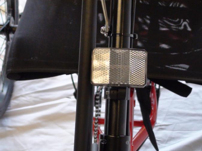
11 1) Attach reflector to bracket, use Phillips head screw. Front Reflector Phillips head screw Bracket Reflector 2) Remove clamp screw, open clamp and place over steering stem tube. Clamp Screw Steering stem tube Reflector bracket n:\amtryke\manuals and instructions\models\hp-1000\hp1000 w-tilt steering assembly.doc 11 of 25
12 Front Brake V-Style Brakes If not already assembled, take the brake noodle from the parts box and slide the cable through the larger opening. The cable housing will then seat into the end of the noodle. Slide the cable through the cable lead on the end of the left brake boot arm; this will cause the noodle to fit into the lead. Slip the brake cable boot over the cable and position it between both brake arms. Next loosen the 5mm anchor bolt at the end of the right brake arm and slide the cable under the retaining washer. Pull the slack out of the cable making sure a distance of 39mm or more remains between the end of the lead and the start of the anchor bolt. Once the cable is secured to the brake arms, engage the brake lever several times, checking the position of the brake shoes at the rim. The brake shoes should be 1mm away from the rim when in a relaxed position. When the brake lever is engaged, the brake shoe should hit the rim flush (never the tire) with the front brake pad touching the rim slightly before the rear. This is called toeing-in your brake shoe. If this position is not achieved, adjustments to the brake shoe are required. Loosen the brake shoe hardware and reposition the brake shoe. It may take several shoe and cable adjustments before the required position is accomplished. V-Brake 1. If fitted with V-Brakes, insert the brake body into the center spring hole in the frame mounting boss, and then secure the brake body to the frame with the link fixing bolt. 2. While holding the shoe against the rim, adjust the amount of shoe protrusion by interchanging the position of the B washers (i.e. 6 mm and 3 mm) so that dimension A is kept at 39 mm or more. n:\amtryke\manuals and instructions\models\hp-1000\hp1000 w-tilt steering assembly.doc 12 of 25
13 3. While holding the shoe against the rim, tighten the shoe fixing nut. 5. Adjust the balance with the spring tension adjustment screws. 4. Pass the inner cable through the inner cable lead. Set the cable with the clearance of 1mm between each brake pad and the rim, tighten the cable fixing bolt. 6. Depress the brake lever about 10 times as far as the grip to check that everything is operating correctly and that the shoe clearance is correct before using the brakes. n:\amtryke\manuals and instructions\models\hp-1000\hp1000 w-tilt steering assembly.doc 13 of 25


14 Cable Retainer 1) Remove the Phillips head screw located on the steering stem tube. Phillips head screw on steering stem tube. 2) Put screw through lower eyelet of cable retainer and thread back into steering stem tube. Phillips head screw through lower eyelet of cable retainer. 3) Attach the cable retainer to upper chain guard bracket using a zip tie. Clip off excess zip tie. Cable retainer attached to upper chain guard bracket with zip tie. n:\amtryke\manuals and instructions\models\hp-1000\hp1000 w-tilt steering assembly.doc 14 of 25
 Use the remaining zip ties and secure the cable to the steering stem tube. Gear shift cable and rear brake cable. Cable retainer secured to steering stem tube with screw.")
15 1) Use a zip tie to attach the three cables to the retainer; this will prevent the cable from wrapping around the hand grips during pedaling. 2) Use the remaining zip ties and secure the cable to the steering stem tube. Gear shift cable and rear brake cable. Cable retainer secured to steering stem tube with screw. Rear brake, Front brake and Gear shift cables attached to the cable retainer with zip tie. Cable retainer attached to upper chain guard bracket with zip tie. n:\amtryke\manuals and instructions\models\hp-1000\hp1000 w-tilt steering assembly.doc 15 of 25.
 Insert the reflector holding pin with the slotted end going over the spoke into the hole in the reflector.")

16 Wheel Reflectors 1) Place the reflector in an area on the rim behind a single spoke with two on the opposite side. Align the front spoke with the slot in the reflector. Reflector Reflector holding pin Single spoke 2) Insert the reflector holding pin with the slotted end going over the spoke into the hole in the reflector. Press firmly until you hear it click into place. Maintenance As is with all other bikes and vehicles that use a chain for the drive line, the chain will eventually come off the sprocket and need to be reinstalled. This next section will serve as a guide on how to reinstall the chain should it come off. 1) Remove the Phillips head screw on the front of the chain guard and the 8mm nut located behind it that secures the two halves of the chain guard together and holds the upper chain guard bracket in place. Remove Phillips head screw and 8mm nut located behind it. (not Shown the 8mm nut) n:\amtryke\manuals and instructions\models\hp-1000\hp1000 w-tilt steering assembly.doc 16 of 25
 Remove the outer chain")
 Use a screwdriver to lift the chain up in the front and turn the hand crank counter")

17 2) The outer chain guard cover will easily remove by lifting up on it, let it wrest on the hand grip. Outer chain guard cover removed chain and sprocket now exposed 3) Remove the outer chain from the lower outer pulley slot located at the base of the steering stem tube. 4) Use a screwdriver to lift the chain up in the front and turn the hand crank counter clockwise while doing so until it grabs the chain and pulls it outwards. Insert screw driver here and lift up on chain. n:\amtryke\manuals and instructions\models\hp-1000\hp1000 w-tilt steering assembly.doc 17 of 25


18 5) Place chain on front side of sprocket and rotate crank arm counter clockwise until chain is on sprocket completely. Front of Sprocket 6) Repeat steps 1, 2 & 3 in reverse to finish reinstalling the chain. Seating Assembly Seat back frame and covering. n:\amtryke\manuals and instructions\models\hp-1000\hp1000 w-tilt steering assembly.doc 18 of 25

19 Front Tire Front tire and quick release axle (Page 5) Quick release axle n:\amtryke\manuals and instructions\models\hp-1000\hp1000 w-tilt steering assembly.doc 19 of 25

20 Rear Deck Assembly Rear deck frame Rear deck frame to main frame mounting hardware Black round nut caps Chain and master link Rear deck and mounting hardware n:\amtryke\manuals and instructions\models\hp-1000\hp1000 w-tilt steering assembly.doc 20 of 25

21 Rear Tires Tire direction must be followed n:\amtryke\manuals and instructions\models\hp-1000\hp1000 w-tilt steering assembly.doc 21 of 25

22 Main Frame Hand cranks Main Steering Tube Front Fork Main hub Leg Supports n:\amtryke\manuals and instructions\models\hp-1000\hp1000 w-tilt steering assembly.doc 22 of 25

23 Hardware Leg support bolt, washers and nut Center steering stem bolt and washer Upper support Allen bolts, washers and nuts Brake noodle and cable cover Cable Retainer n:\amtryke\manuals and instructions\models\hp-1000\hp1000 w-tilt steering assembly.doc 23 of 25

24 Steering Linkage Steering Linkage n:\amtryke\manuals and instructions\models\hp-1000\hp1000 w-tilt steering assembly.doc 24 of 25

25 Reflectors Rear reflector and bracket Front reflector and bracket Wheel reflectors and spoke securing pins Questions or Concerns Regarding your Build? No problem! Please Contact Derek Shaw, AmTryke Technical and Customer Support x114 or dereks@ambucs.org n:\amtryke\manuals and instructions\models\hp-1000\hp1000 w-tilt steering assembly.doc 25 of 25
AmTryke Adult Recumbent Model JT2000 #50-FC-2000
 AmTryke Adult Recumbent Model JT2000 #50-FC-2000 TOOLS Needed for Assembly 5 mm Allen Wrench 8 mm Socket or Wrench 10 mm Socket or Wrench 14 mm Socket or Wrench 15 mm Socket or Wrench 22 mm Socket or Adjustable
Amtryke Model AM-12 & AM-16
 Amtryke Model AM-12 & AM-16 Carton Contents Carefully remove and lay out all parts from the carton so as not to scratch or lose any parts or pieces. The shipping carton should contain the pictured items
CHAINGUARD REGAL ST COLOR
 DESOTO/ REGAL HAULER PARTS LIST Item Part # Description QTY Item Part # Description QTY 1 11871 REFLECTOR KIT TRIKE 1 32 11764 FENDER BRACE 24" MWT 1 2 12199 SCREW #14 x 3/4 4 33 12176 NUT5/16-24 HEX 2
CHAINGUARD REGAL ST COLOR
 DESOTO/ REGAL HAULER PARTS LIST Item Part # Description QTY Item Part # Description QTY 1 11871 REFLECTOR KIT TRIKE 1 32 11762 FENDER BRACE 20" MWT 1 2 12199 SCREW #14 x 3/4 4 11764 FENDER BRACE 24" MWT
CALIFORNIA TRIMMER MOWER MAINTENANCE MANUAL
 CALIFORNIA TRIMMER MOWER MAINTENANCE MANUAL 2 Table of Contents Section 1: General Information Page Handle Assembly Instructions 4 Maintenance All Models 6 Oil Change Procedures All Models 9 Height Adjustment
INSTALLATION INSTRUCTIONS
 INSTALLATION INSTRUCTIONS REAR DRUM TO DISC BRAKE CONVERSION KIT A130 JEEP CJ SERIES W/AMC-20 REAR AXLES AND 5 x 5-1/2" BOLT CIRCLE Thank you for choosing STAINLESS STEEL BRAKES CORPORATION for your braking
Final Assembly Instructions Portside Cruiser
 Final Assembly Instructions Portside Cruiser Thank you for buying your new bicycle from L.L.Bean. Read these instructions carefully before beginning the final assembly. Prior to shipping, our expert cycling
This is the Unpacking Guide for the Optibike Pioneer Allroad electric bicycle. The Guide provides information required to remove the Allroad from the
 This is the Unpacking Guide for the Optibike Pioneer Allroad electric bicycle. The Guide provides information required to remove the Allroad from the box and assemble it. If you have not assembled a bicycle
1989 Jeep Cherokee. STEERING COLUMN' '1989 STEERING Jeep Steering Columns STEERING COLUMN STEERING Jeep Steering Columns
 STEERING COLUMN 1989 STEERING Jeep Steering Columns DESCRIPTION All models use collapsible steering columns. All columns have integral ignition switch and locking device. Optional tilt wheel is available
Final Assembly Instructions: Bikes with Threadless Headsets
 Final Assembly Instructions: Bikes with Threadless Headsets Thank you for buying your new bicycle from L.L.Bean. Read these instructions carefully before beginning the final assembly. Prior to shipping,
Final Assembly Instructions: Runaround Cruiser
 Final Assembly Instructions: Runaround Cruiser Thank you for buying your new bicycle from L.L.Bean. Read these instructions carefully before beginning the final assembly. Prior to shipping, our expert
Comfort Tri-Rider Assembly Guide
 1. Carefully remove all the components and packaged hardware from the shipping boxes. 2. Remove all protective materials from the fork, front frame and rear frame sections. 3. Read this assembly manual
INSTALLATION INSTRUCTIONS
 INSTALLATION INSTRUCTIONS REAR DRUM TO DISC BRAKE CONVERSION KIT A118 pre-1985 Ford F150 (except 1983-1984 w/super H/D axle) Thank you for choosing STAINLESS STEEL BRAKES CORPORATION for your braking needs.
INSTALLATION INSTRUCTIONS 97 FORD EXPEDITION
 INSTALLATION INSTRUCTIONS 97 FORD EXPEDITION 1. Read the instructions completely and carefully before you begin. Check the kit for proper contents (refer to the part s list and the picture diagrams). Before
Assault Air Bike Assembly Instructions
 Assault Air Bike Assembly Instructions Tools Needed: Box Cutter 6mm Hex Wrench Phillips Screw Driver 13mm Wrench 22mm Wrench 15mm Wrench Step 1: Lay the Assault Airbike Bike box on the ground. Step 3:
Self-propelled Chipper Shredder Vacuum
 2.11. Confirm that the drive gears are installed on the correct side. See Figure 2.11. 3. TRANSMISSION REMOVAL 3.1. Disconnect the H.T. lead from the spark plug. 3.2. Remove collection bag or blower chute.
INSTALLATION INSTRUCTIONS
 INSTALLATION INSTRUCTIONS REAR DISC CONVERSION KIT A126-2 1988-98 C1500 2WD 10" REAR DRUM Thank you for choosing STAINLESS STEEL BRAKES CORPORATION for your braking needs. Pleases take the time to read
Final Assembly Instructions Casco Bay Cruiser
 Final Assembly Instructions Casco Bay Cruiser Thank you for buying your new bicycle from L.L.Bean. Read these instructions carefully before beginning the final assembly. Prior to shipping, our expert cycling
Go-ped ESR750 / ESR750EX Rear Brake Installation Instructions
 Go-ped ESR750 / ESR750EX Rear Brake Installation Instructions This kit provides all the parts you need to install a rear brake on your ESR750 or ESR750EX. It will not work on an ESR Sport, or other Go-ped
Installation Instructions COMPETITION/PLUS SHIFTER Ford Mustang MT82 6-Speed Manual Transmission Catalog#
 Installation Instructions COMPETITION/PLUS SHIFTER 2015-2017 Ford Mustang MT82 6-Speed Manual Transmission Catalog# 3916037 Rev. 00 WORK SAFELY! For maximum safety, perform this installation on a clean,
TSS Fit Kit Installation Instructions Timbersled Snow Bike System
 TSS Fit Kit Installation Instructions Timbersled Snow Bike System Information needed before you start: Read the entire installation instructions before starting. The instruction sheet is universal for
Repair Manual 11/99 PS-34. Page 1
 Repair Manual /99 PS-4 Page Table of contents Index Technical Data page Special tools 4 Repair instructions, general 0 Chain brake 6 0 Centrifugal clutch 8 0 Oil pump 9-04 Ignition system - 0 Starting
INSTALLATION INSTRUCTIONS
 INSTALLATION INSTRUCTIONS INSTALLATION INSTRUCTIONS FOR A136 REAR DRUM TO DISC BRAKE CONVERSION KIT for 1970-75 Jeep, CJ SERIES with Dana 44 flanged axle Thank you for choosing STAINLESS STEEL BRAKES CORPORATION
Installation Instructions
 86-89 Suzuki Samurai Pedal Rebuild Kit SKU# SIB-PRB! Instructions also includes clutch adjustment procedures. Installation Instructions W e a l s o s u p p l y replacement peddle pads. Click HERE for more
INSTALLATION INSTRUCTIONS
 INSTALLATION INSTRUCTIONS REAR DISC BRAKE CONVERSION KIT A126-1 1973-87 CHEVROLET 1/2 TON 2WD Thank you for choosing STAINLESS STEEL BRAKES CORPORATION for your braking needs. Pleases take the time to
Type 2 Push-Through 37 Ton Log Splitter. Assembly Manual
 Type 2 Push-Through 37 Ton Log Splitter Assembly Manual Refer to this manual for the following models: RS37PT-LF09PC-16-1 RS37PT-LF09EC-16-1 RS37PT-LF09EC-16-2 RS37PT-LF13EC-22-1 RS37PT-LF13EC-22-2 RS37PT-LF15EC-22-1
Installation Manual TWM Performance Short Shifter Subaru STi 2008+
 - 1 - Installation Manual TWM Performance Short Shifter Subaru STi 2008+ Please Note: It is preferable to park on a flat surface, as you will have to engage and disengage the hand brake and shift from
Push Start Ignition (05-10 All) Installation
 Installation") Tools Required: Phillips head screwdriver Flat head screwdriver Ratchet 7mm Socket Torx T20 bit Wire strippers/cutters Hand file Needle nose pliers Installation Instructions: Push Start Ignition (05-10
Tools Required: Phillips head screwdriver Flat head screwdriver Ratchet 7mm Socket Torx T20 bit Wire strippers/cutters Hand file Needle nose pliers Installation Instructions: Push Start Ignition (05-10
Amtryke Model Snappy #
 Amtryke Model Snappy #50-0150 Carton Contents Carefully remove and lay out all parts from the carton so as not to scratch or lose any parts or pieces. The shipping carton should contain the pictured items
1. Single-speed bicycle (SSB) lower fork legs... Page 3 2. Multi-speed bicycle (MSB) lower fork legs... Page 4
 lower fork legs... Page 3 2. Multi-speed bicycle (MSB) lower fork legs... Page 4") TM owner s instruction manual the ULTIMATE SURFBOARD RACK I. Messages & Warnings...Page 2 II. FORK BASE UNIT COMPONENTS...Page 2 III. SELECTING PROPER LEG TYPE...Page 2 IV. LEG LENGTH ADJUSTMENT & FORK
TM owner s instruction manual the ULTIMATE SURFBOARD RACK I. Messages & Warnings...Page 2 II. FORK BASE UNIT COMPONENTS...Page 2 III. SELECTING PROPER LEG TYPE...Page 2 IV. LEG LENGTH ADJUSTMENT & FORK
RHINO SUSPENSION SYSTEM INSTALLATION INSTRUCTIONS
 PARTS INCLUDED: 2 FRONT UPPER A-ARMS 2 FRONT LOWER A-ARMS 2 UNI-BALL JOINTS 2 UNI-BALL JOINT STUDS 2 UNI-BALL JOINT CAPS 2 RETAINING RINGS 1 FRONT SHOCK ASSEM. 2 DELRON STEERING STOPS 2 SHOCK MOUNT SPACERS
INSTALLATION INSTRUCTIONS
 INSTALLATION INSTRUCTIONS REAR DISC BRAKE CONVERSION KIT A157 1991-2004 Dodge Dakota 2WD 1991-2002 Dodge Dakota 4WD 1998-2002 Dodge Durango Thank you for choosing STAINLESS STEEL BRAKES CORPORATION for
EZ LITE CRUISER. Service & Maintenance Manual
 EZ LITE CRUISER Service & Maintenance Manual Table Of Contents Introduction to the EZ Lite Cruiser 3 Identification of Components 4 Controller System Component Diagram 6 Controller System I/O Ports Detail
Next, chase the threads in the lower A-arm mounts with the 5/8-18 tap and blowout any remaining particles.
 Next, chase the threads in the lower A-arm mounts with the 5/8-18 tap and blowout any remaining particles. Now, apply some anti-seize to the threads of the pivot stud. Also put anti-seize inside the bore
Amtryke Model AM-12 #50-HFC-0210 Amtryke Model AM-16 #50-HFC-0411 Note: Shown with Saddle Seat and Curved Plastic Seat Back
 Amtryke Model AM-12 #50-HFC-0210 Amtryke Model AM-16 #50-HFC-0411 Note: Shown with Saddle Seat and Curved Plastic Seat Back Carton Contents Carefully remove and lay out all parts from the carton so as
J & D Machine / Hyperdrive / MSA 3711 Moon Bend Rd. Chapel Hill, TN 37034
 J & D Machine / Hyperdrive / MSA 3711 Moon Bend Rd. Chapel Hill, TN 37034 www.hyperdriveracing.com 1 You now own a state of the art 1/10 scale oval race car. The Hyperdrive Assault has gone through months
EGR Performance Brakes Assembly Instructions DODGE DANA 70 '87 - '93 (Will not fit stock sized dual rear wheels)
") EGR Performance Brakes Assembly Instructions DODGE DANA 70 '87 - '93 (Will not fit stock sized dual rear wheels) Got Brakes? Parts List (2) Vented Rotors (2) Multi hole Cable Mount & L Brkt (2) Axle Tube
EGR Performance Brakes Assembly Instructions DODGE DANA 70 '87 - '93 (Will not fit stock sized dual rear wheels) Got Brakes? Parts List (2) Vented Rotors (2) Multi hole Cable Mount & L Brkt (2) Axle Tube
InstalL Instructions. trail-creeper 4.70 transfer case gear kit ( KIT and KIT) kit contents
 kit contents") InstalL Instructions trail-creeper 4.70 transfer case gear kit (105000-1-KIT and 105001-1-KIT) kit contents 5356 PINE AVE FRESNO, CA 93727 USA TOLL FREE: 877.4X4.TOYS WORLDWIDE: 559.252.4950 WWW.TRAIL-GEAR.COM
InstalL Instructions trail-creeper 4.70 transfer case gear kit (105000-1-KIT and 105001-1-KIT) kit contents 5356 PINE AVE FRESNO, CA 93727 USA TOLL FREE: 877.4X4.TOYS WORLDWIDE: 559.252.4950 WWW.TRAIL-GEAR.COM
Owner s Manual Read and keep this manual. Patents World Wide
 Owner s Manual Read and keep this manual. Patents World Wide S & S Industries, Inc., Sarasota, FL, USA www.trail-gator.com Copyright 2006 All Rights Reserved The following manual is provided to assist
Online version - not for reprint
 4. CLUTCH, CHAIN DRIVE, CHAIN BRAKE, CHAIN TENSIONER 4. Clutch Drum/Chain Sprocket 43RA007 VA 70RA005 VA - Remove the chain sprocket cover. Disengage the chain brake by pulling the hand guard toward the
INSTALLATION INSTRUCTIONS
 INSTALLATION INSTRUCTIONS INSTRUCTION FOR ASSEMBLY OF JEEP CJ SERIES W/AMC 20 REAR AXLES, 5 x 5-1/2" BOLT CIRCLE WITH A130-1 FULL FLOATING AXLE OR A130-2 (1 PIECE AXLE) Thank you for choosing STAINLESS
SCION FR-S FOG LIGHTS
 Part #: PT413-18130 Conflicts: Lowering Springs PTR07-18130-LL (California only) Kit Contents: For Anniversary Edition, Monogram & RS 2.0 vehicles, additional parts need to be ordered (PT413-18130-LL)
P4 CHAINSTAY INTEGRATED ROCKER BRAKE (CSIRB) INSTALLATION
 INSTALLATION") P4 CHAINSTAY INTEGRATED ROCKER BRAKE (CSIRB) INSTALLATION TOOLS REQUIRED 2, 2.5, 3, 5 mm allen keys 8, 9 mm open faced cone wrench Pliers Cable cutters Torque wrench MATERIALS REQUIRED: 1 x P4 chainstay
P4 CHAINSTAY INTEGRATED ROCKER BRAKE (CSIRB) INSTALLATION TOOLS REQUIRED 2, 2.5, 3, 5 mm allen keys 8, 9 mm open faced cone wrench Pliers Cable cutters Torque wrench MATERIALS REQUIRED: 1 x P4 chainstay
Timing Chain: Service and Repair With 2 Piece Tensioner (TSB A) Precaution. Removal This article has been updated with bulletin No A.
 Precaution. Removal This article has been updated with bulletin No A.") 1997 Chevrolet Cavalier L4-144 2.4L DOHC VIN T SFI Page 1 Timing Chain: Service and Repair With 2 Piece Tensioner (TSB 67-61-22A) Precaution Bulletin No.: 67-61-22A Date: July, 1998 TIMING CHAIN TENSIONER
1997 Chevrolet Cavalier L4-144 2.4L DOHC VIN T SFI Page 1 Timing Chain: Service and Repair With 2 Piece Tensioner (TSB 67-61-22A) Precaution Bulletin No.: 67-61-22A Date: July, 1998 TIMING CHAIN TENSIONER
Procedure Replacing a Cover
 Procedure 7.1 - Replacing a Cover Cover Removal 1. Remove two screws, one each side, from the front of the top cover. Remove the top cover. See Diagram 7.1. Diagram 7.1 - RBK 815 Covers Top Cover Left
Section 5: Parts Replacement
 Section 5: Parts Replacement Should the STAR TRAC 4500 Treadmill experience a problem requiring replacement of a specific part, the following procedures will help and instruct in the replacement of major
CHASSIS CONTENTS FRONT WHEEL 6-1 FRONT BRAKE 6-6 FRONT FORK 6-14 STEERING STEM 6-20 REAR WHEEL AND REAR BRAKE 6-25 SUSPENSION 6-31 REAR SWING ARM 6-36
 CHASSIS CONTENTS FRONT WHEEL 6-1 FRONT BRAKE 6-6 FRONT FORK 6-14 STEERING STEM 6-20 REAR WHEEL AND REAR BRAKE 6-25 SUSPENSION 6-31 REAR SWING ARM 6-36 6 6-1 CHASSIS FRONT WHEEL REMOVAL Support the machine
Maintenance Information
 Form 04584058 Edition 1 November 2004 Air Impactool 2141P and 2141PSP Maintenance Information Save These Instructions Disassembly General Instructions 1. Do not disassemble the tool any further than necessary
2006 MINI Cooper SUSPENSION Wheels & Tires - Repair Instructions - Cooper (1.6L) R50/W10 & Cooper S
 R50/W10 & Cooper S") WHEELS 2002-05 SUSPENSION Wheels & Tires - Repair Instructions - Cooper (1.6L) R50/W10 & Cooper S 36 10 300 REMOVING OR INSTALLING FRONT OR REAR WHEEL NOTE: For Special Tool identification, see WHEEL AND
WHEELS 2002-05 SUSPENSION Wheels & Tires - Repair Instructions - Cooper (1.6L) R50/W10 & Cooper S 36 10 300 REMOVING OR INSTALLING FRONT OR REAR WHEEL NOTE: For Special Tool identification, see WHEEL AND
M-7210-Z3 Focus Short-Throw Shifter (fits 2000-April 2002) INSTALLATION INSTRUCTIONS
 INSTALLATION INSTRUCTIONS") Please visit www.fordracingparts.com for the most current instruction information!!! PLEASE READ ALL OF THE FOLLOWING INSTRUCTIONS CAREFULLY PRIOR TO INSTALLATION. AT ANY TIME YOU DO NOT UNDERSTAND THE
Please visit www.fordracingparts.com for the most current instruction information!!! PLEASE READ ALL OF THE FOLLOWING INSTRUCTIONS CAREFULLY PRIOR TO INSTALLATION. AT ANY TIME YOU DO NOT UNDERSTAND THE
MailStar Maintenance and Adjustment March 2002
 MailStar Maintenance and Adjustment March 2002 The MailStar bicycle incorporates many new features to ease maintenance and improve handling and performance. The majority of components are similar to those
Shown with optional GFR-1017R Body Posts. J & D Machine / Hyperdrive / MSA 3711 Moon Bend Rd. Chapel Hill, TN
 Shown with optional GFR-1017R Body Posts J & D Machine / Hyperdrive / MSA 3711 Moon Bend Rd. Chapel Hill, TN 37034 www.hyperdriveracing.com 1 You now own a state of the art 1/10 scale oval race car. The
TECHNICAL BULLETIN. TP Issued Servicing Rockwell s TB Series Trailer Axles with Unitized Hub Assemblies
 TECHNICAL BULLETIN TP-96175 Issued 12-96 Servicing Rockwell s TB Series Trailer Axles with Unitized Hub Assemblies TB Series Trailer Axles Introduction Rockwell s TB series trailer axle features a permanently
Installation Instructions Table of Contents
 Installation Instructions Table of Contents Pre- Installation of Garage Storage Lift 2 Layout the Garage Storage Lift 3 Installing the strut Channels 3 Install the Drive Assembly 5 Install the Drive Shaft
w w w. h d o n l i n e s h o p. d e CRUISE CONTROL KIT GENERAL INSTALLATION -J04064 REV Kit Number Models Additional Parts Required
 -J006 REV. 006-08- CRUISE CONTROL KIT GENERAL Kit Number 7796-07 Models For the most up-to-date model fitment information, please see the product label or www.harley-davidson.com. Additional Parts Required.
Installation Instructions
 Preparing your vehicle to install your brake system upgrade 1. Rack the vehicle. 2. If you don t have a rack, then you must take extra safety precautions. 3. Choose a firmly packed and level ground to
Sachs shock manual. ( ) 2 & 4 Stroke RR Enduro. ( ) RS Dual Sport
 2 & 4 Stroke RR Enduro. ( ) RS Dual Sport") Sachs shock manual (2013 2015) 2 & 4 Stroke RR Enduro (2014-2015) RS Dual Sport 1 Introduction The procedures in this manual must take place in a clean environment using professional tools and some specific,
Sachs shock manual (2013 2015) 2 & 4 Stroke RR Enduro (2014-2015) RS Dual Sport 1 Introduction The procedures in this manual must take place in a clean environment using professional tools and some specific,
MOUNTAIN HORSE INSTALL KIT
 MOUNTAIN HORSE INSTALL KIT P/N 9928508 APPLICATION Installation Instructions are for all Mountain Horse TSS and TFS Installation Kits and Timbersled Mountain Horse chassis installations. The Timbersled
DL650 Odyssey Luggage Installation Guide
 DL650 Odyssey Luggage Installation Guide Thank you for purchasing Jesse Luggage for your Motorcycle. Our Luggage, handcrafted in the USA, is designed for those with an interest in finding the most durable
Commander SUSPENSION SYSTEM INSTALLATION INSTRUCTIONS
 PARTS INCLUDED: 2 - FRONT UPPER A-ARMS 2 - FRONT LOWER A-ARMS 4 - COTTER PINS 2-12MM JAM NUTS 2 - TIE ROD EXTENDERS 8- FLANGED DELRON BUSHINGS 4- DELRON CASTER SPACERS 6 - GREASE FITTINGS 3 - BEARING REMOVAL
Installation Guide Currie Electro-Drive Conversion Kits 2, 3, & 4
 Installation Guide Currie Electro-Drive Conversion Kits 2, 3, & 4 1 Before you start... Use this information to determine whether one of our kits will fit your bike Drawing Ref. Fork Area Leg clearance
FOR SIT-STAND WORKSTATION
 INSTALLATION MANUAL FOR SIT-STAND WORKSTATION Weight Capacity: 6.5-24.5 lbs. 6017180 Rev. B Contents Tools Required / Supplied Part Kits / Warnings/Disclaimers...2 Base Installation Clamp Mount Base Location...3
INSTALLATION INSTRUCTIONS
 INSTALLATION INSTRUCTIONS REAR DISC BRAKE CONVERSION KIT A158 1994-97 Dodge Ram 1500 (2WD & 4WD) and REAR DISC BRAKE CONVERSION KIT A158-1 1998-01 Dodge Ram 1500 (2WD & 4WD) Thank you for choosing STAINLESS
Part list for Kawasaki H2, 1972
 Part list for Kawasaki H2, 972 . Cylinder head, cylinder. . Cylinder head, cylinder. 9205-049 NUT 0 m/m 2 2 40B400 WASHER-plain 4 m/m 2 3 46E400 WASHER-spring 4 m/m 2 4 92070-036 SPARK PLUG NGK B9 HS 3
A B C D E F. b.tools Required (supplied by others) 3/16" Drill Bit 3/8" Wrench Phillips Head Screwdriver
 3/16 Drill Bit 3/8 Wrench Phillips Head Screwdriver") Page 1 of 13 5E.1 Parts List a. Below Deck Automatic Retractable Security Cover Kit (1) Tube End Bearing Plate (A) (1) Rope Reel with Motor Attached (B) (1) Rope Reel Cover (C) (1) Cover Drum (1) Cover
Page 1 of 13 5E.1 Parts List a. Below Deck Automatic Retractable Security Cover Kit (1) Tube End Bearing Plate (A) (1) Rope Reel with Motor Attached (B) (1) Rope Reel Cover (C) (1) Cover Drum (1) Cover
Sherco Setup and Lubrication Guide
 Sherco Setup and This guide is designed to provide the Sherco owner with instructions on how to: Set up a new bike Clean and re-oil the air filter Change the transmission oil Change the fork oil Repack
Installation Manual TWM Performance Short Shifter Cobalt SS/SC, SS/TC, HHR SS, Ion Redline and Saab 9-3
 Page 1 Installation Manual TWM Performance Short Shifter Cobalt SS/SC, SS/TC, HHR SS, Ion Redline and Saab 9-3 Please Note: It is preferable to park on a flat surface, as you will have to engage and disengage
Part s Catalog. GT2100 Garden Tractor. Model No. 14AP80RP744. Original Instructions (EN) (01/31/06)
 (01/31/06)") Part s Catalog GT0 Garden Tractor Model No. AP0RP Original Instructions (EN) -0 (0//0) Model P0RP -0-00 Turf Tire, x. x -0-00 Rim,.0 x.0-00 Lug Nut, /- -00A-0 Wheel Assembly, x. x -00-00 Rim Assembly,.0
Part s Catalog GT0 Garden Tractor Model No. AP0RP Original Instructions (EN) -0 (0//0) Model P0RP -0-00 Turf Tire, x. x -0-00 Rim,.0 x.0-00 Lug Nut, /- -00A-0 Wheel Assembly, x. x -00-00 Rim Assembly,.0
SOP Instructions & Check Sheet for MATRIX X Bike Installation
 1000390 Rev 2 SOP Instructions & Check Sheet for MATRIX X Bike Installation Tools Needed 1. 13mm, 15mm (for pedals) and 17mm wrenches 2. Metric Hex Keys (long) set including 3mm, 4mm, 5mm, and 6mm. 3.
Brake System H TX, H2.0TXS [B475]; H TX [B466] Safety Precautions Maintenance and Repair
![Brake System H TX, H2.0TXS [B475]; H TX [B466] Safety Precautions Maintenance and Repair](/thumbs/86/93834005.jpg "Brake System H TX, H2.0TXS [B475]; H TX [B466] Safety Precautions Maintenance and Repair") HMM180001 Brake System H1.5-1.8TX, H2.0TXS [B475]; H2.5-3.5TX [B466] Safety Precautions Maintenance and Repair When lifting parts or assemblies, make sure all slings, chains, or cables are correctly fastened,
HMM180001 Brake System H1.5-1.8TX, H2.0TXS [B475]; H2.5-3.5TX [B466] Safety Precautions Maintenance and Repair When lifting parts or assemblies, make sure all slings, chains, or cables are correctly fastened,
BRAKE SYSTEM Toyota Celica DESCRIPTION DRUM BRAKES ADJUSTMENTS BRAKE PEDAL HEIGHT ADJUSTMENTS BRAKE PEDAL FREE PLAY ADJUSTMENTS
 BRAKE SYSTEM 1988 Toyota Celica 1988-89 BRAKES Toyota Celica, Corolla, MR2, Tercel DESCRIPTION The hydraulic brake system uses a tandem master cylinder with a vacuum power assist servo. MR2 and some Celica
Release the electrical wire from the bracket -2- toward the left -A- and remove.
 Page 1 of 8 Front Brake Pads, FBC-60, Removing and Installing Always replace on both axles. Special tools and workshop equipment required t Torque Wrench 5 50 Nm -V.A.G 1331- t Reversible Ratchet -V.A.G.
Torqueflite Manual/Automatic Valve Body
 TCI 122400 Torqueflite Manual/Automatic Valve Body This valve body can be installed in a few hours by carefully following directions. Read all instructions first to familiarize yourself with the parts
Service Manual Air Tech Second Stage
 Service Manual Air Tech Second Stage Copyright 2002, Cressi-sub Revised 3/2002 2 Air Tech Second Stage Service Manual Contents BEFORE STARTING... 3 DISASSEMBLY... 3 PARTS CLEANING AND LUBRICATION... 9
2013 RT / 2014RT / 2015 RT - Shock Spring Adjuster Installation Instructions
 2013 RT / 2014RT / 2015 RT - Shock Spring Adjuster Installation Instructions Billet Aluminum Adjusters (2) Shock Spring Compressors (Optional) Spanner Wrench (1) BajaRon Decals Not Shown (4) Adjuster Scuff
INSTALLATION INSTRUCTIONS
 INSTALLATION INSTRUCTIONS REAR DISC BRAKE CONVERSION KIT A126-3 1988-98 CHEVY K1500 4WD 10" DRUMS Thank you for choosing STAINLESS STEEL BRAKES CORPORATION for your braking needs. Pleases take the time
Installation Manual TWM Performance Full replacement short shifter assembly Civic all trims and models
 Installation Manual TWM Performance Full replacement short shifter assembly 2006+ Civic all trims and models Begin the installation by parking on a flat surface, as you will have to engage and disengage
TRANSMISSION 6.7 GENERAL HOME. See Figure The transmission is a five-speed constantmesh type housed in an extension of the crankcase.
 TRANSMISSION 6.7 GENERAL See Figure 6-45. The transmission is a five-speed constantmesh type housed in an extension of the crankcase. Mainshaft Neutral Mainshaft st Gear b06x6x Countershaft 4 Out 5 Countershaft
FRONT DRIVE SHAFT COMPONENTS DS 1 DRIVE SHAFT FRONT DRIVE SHAFT FRONT DRIVE SHAFT HOLE SNAP RING. w/o ABS: AUTOMATIC TRANSMISSION CASE PROTECTOR
 FRONT DRIVE SHAFT DRIVE LINE SHAFT COMPONENTS 1 FRONT DRIVE SHAFT HOLE SNAP RING 23 (235, 17) FRONT DRIVE SHAFT ASSEMBLY RH w/o ABS: AUTOMATIC TRANSMISSION CASE PROTECTOR FRONT DRIVE SHAFT ASSEMBLY LH
A B C D E F. Tools Required (supplied by others)
") Page 1 of 17 Parts List Below Deck Automatic Retractable Security Cover Kit (1) Tube End Bearing Plate (A) (1) Rope Reel and Cover Drum Motor Assembly (B) (1) Cover Drum (1) Pulley Support Channel (2)
Page 1 of 17 Parts List Below Deck Automatic Retractable Security Cover Kit (1) Tube End Bearing Plate (A) (1) Rope Reel and Cover Drum Motor Assembly (B) (1) Cover Drum (1) Pulley Support Channel (2)
Slave Cylinder Weep Hole Drilling Procedure
 Slave Cylinder Weep Hole Drilling Procedure Tools Required: T20 Torx Driver T25 Torx Driver T25 Torx Bit with ¼ Ratchet Wrench 4mm Hex Key (Allen wrench) 5mm Hex Key 6mm Hex Key 8mm Hex Key 12mm Hex Key
401B/1KDB CoolRite/FreezeRite Installation Manual I003
 401B/1KDB CoolRite/FreezeRite Installation Manual 99-16105-I003 Copyright 2011 by ALL rights reserved. Information in this document is subject to change without notice. Companies, names and data used in
GM Full-Size Trucks Repair Information
 . 1 of 12 12/26/2009 10:47 AM GM Full-Size Trucks 1988-1998 Repair Information Brake Shoes INSPECTION REMOVAL & INSTALLATION ADJUSTMENT INSPECTION 1. 2. 3. 4. 5. Raise and support the rear end on jackstands.
Installation Instructions Z-Gate Shifter
 Installation Instructions Z-Gate Shifter Part Number 80681 1998, 2001 by B&M Racing and Performance Products The B&M Z-Gate shifter can be used in vehicles equipped with most popular three speed automatic
ATV 90 UTILITY GREEN (A2006KUB2BUSG) Page 1 of 60 AIR INTAKE ASSEMBLY
 Page 1 of 60 AIR INTAKE ASSEMBLY") 2006 ATV 90 UTILITY GREEN (A2006KUB2BUSG) Page 1 of 60 AIR INTAKE ASSEMBLY 2006 ATV 90 UTILITY GREEN (A2006KUB2BUSG) Page 2 of 60 AIR INTAKE ASSEMBLY Ref # Part Number Qty S/P/F Description 1 3303-005
2006 ATV 90 UTILITY GREEN (A2006KUB2BUSG) Page 1 of 60 AIR INTAKE ASSEMBLY 2006 ATV 90 UTILITY GREEN (A2006KUB2BUSG) Page 2 of 60 AIR INTAKE ASSEMBLY Ref # Part Number Qty S/P/F Description 1 3303-005
90 Utility Model Number A2013KUB2BUSZ SHARE OUR PASSION.
 2013 90 Utility Model Number A2013KUB2BUSZ TM SHARE OUR PASSION. TABLE OF CONTENTS 2013 ATV 90 (Model No. A2013KUB2BUSZ) BODY PANEL AND HEADLIGHT ASSEMBLY... 1 FRONT AND REAR RACK ASSEMBLY... 2 FRAME AND
LOW, MID, HIGH RISE PRO-TAPER HANDLEBAR WITH HEATED GRIPS KIT
 LOW, MID, HIGH RISE PRO-TAPER HANDLEBAR WITH HEATED GRIPS KIT P/N 2881235; 2881236; 2881237 APPLICATION All AXYS and PRO RIDE chassis with stock Pro-Taper Bar BEFORE YOU BEGIN Read these instructions and
Assembly Manual. 1/10th Formula 1 Car
 Assembly Manual 1/10th Formula 1 Car Center Pivot Bag 1 3374 - Center Pivot Socket 40194 - Hard Anodized Alum Pivot ball 3254-2-56 *Note - Sometimes it is helpful to slightly over-tighten the top clamp
18. REAR WHEEL/SUSPENSION
 18. REAR WHEEL/SUSPENSION SYSTEM COMPONENTS 182 REAR AXLE/BEARING HOLDER 187 SERVICE INFORMATION 183 REAR SHOCK ABSORBER 1816 TROUBLESHOOTING 186 SHOCK LINKAGE 1818 REAR WHEEL 187 SWINGARM 1820 181 SYSTEM
REMOVAL & INSTALLATION
 REMOVAL & INSTALLATION Removal 1. Center steering wheel. Disconnect negative battery cable. Remove steering coupling shield (if equipped). Disconnect steering shaft at flexible coupling or pot joint. Note
M GT 2005 up Mustang ENGINE START Push-Button INSTRUCTION SHEET
 Please contact the Ford Racing Techline for the most current instruction information @ (800) FORD-788!!! PLEASE READ THE FOLLOWING INSTRUCTIONS CAREFULLY PRIOR TO INSTALLATION!!! OVERVIEW: The following
TRANSMISSION 6.7 GENERAL HOME. See Figure The transmission is a five-speed constantmesh type housed in an extension of the crankcase.
 TRANSMISSION 6.7 GENERAL See Figure 6-46. The transmission is a five-speed constantmesh type housed in an extension of the crankcase. b06x6x Neutral st Gear Mainshaft Mainshaft 4 5 4 5 Countershaft Out
OLYMPIAN MODEL 740 Operation and Service Manual
 OLYMPIAN MODEL 740 Operation and Service Manual P/N 133911-102 FCI MANUAL P/N 133865-001 Data herein has been verified and validated and believed adequate for the intended use. If the machine or procedures
INSTALLATION INSTRUCTIONS
 INSTALLATION INSTRUCTIONS REAR DISC BRAKE CONVERSION KITS A112, A112-1 & A112-93 1979-93 FORD MUSTANG with 7.5" & 8.8" AXLES Thank you for choosing STAINLESS STEEL BRAKES CORPORATION for your braking needs.
FRONT RACK, BODY PANEL, AND HEADLIGHT ASSEMBLIES
 FRONT RACK, BODY PANEL, AND HEADLIGHT ASSEMBLIES 0747-506 1 2506-107 1 Rack, Front - Assembly (inc. 2) 2 0411-576 1 Decal, Warning - Load 3 0441-592 4 Bushing 4 8410-835 4 Screw, Cap 5 0423-669 4 Spacer
A/C COMPRESSOR SERVICING Article Text 1991 Saab 9000 For Copyright 1997 Mitchell International Friday, October 15, :22PM
 Article Text ARTICLE BEGINNING 1991 GENERAL SERVICING Compressor Service * PLEASE READ THIS FIRST * CAUTION: When discharging air conditioning system, use only approved refrigerant recovery/recycling equipment.
INSTALLATION INSTRUCTIONS
 INSTALLATION INSTRUCTIONS R1 REAR DRUM TO DISC BRAKE CONVERSION KIT A130-3 JEEP CJ SERIES W/AMC-20 REAR AXLES AND 5 x 5-1/2" BOLT CIRCLE Thank you for choosing STAINLESS STEEL BRAKES CORPORATION for your
F Bracket Top Cushion PCS R 3.67 F02-02 GB/T Bulb 12V 1.7W PCS R 6.12 F02-03 GB/T Bulb 12V 3.4W PCS R 6.12 F
 F01-01 2471033100 Headlightassy PCS R 367.23 F01-02 2471033150 Clip PCS R 91.81 F01-03 2471033130 Headlight Lens PCS R 69.77 F01-04 2471033115 Spring Clip PCS R 3.67 F01-05 2471033181 Clip PCS R 3.67 F01-06
Z-Gate Universal Shifter
 Installation Instructions Z-Gate Universal Shifter Fits: GM, Ford, Lincoln and Chrysler Transmissions See Application Guide for Specific Applications Part #80681 Rev 06/01/2018 WORK SAFELY! For maximum
Installation Manual TWM Performance Kia Forte Short Shifter
 Installation Manual TWM Performance Kia Forte 2009+ Short Shifter Begin the installation by parking on a flat surface, as you will have to engage and disengage the hand brake and shift from gears to neutral.