STIGA PARK 4 WD 107 M 107 M HD 121 M. 125 Combi Pro B INSTRUCTIONS FOR USE. »HC P K»fl œoà «Œ EÀfl
|
|
|
- Solomon Davidson
- 5 years ago
- Views:
Transcription
1 STIGA PARK 4 WD 107 M 107 M HD 121 M 125 Combi Pro B INSTRUCTIONS FOR USE»HC P K»fl œoà «Œ EÀfl


2 1 125 Combi Pro Combi Pro Combi Pro 121 M 107 M HD A B C B Combi Pro 107 M HD 121 M Combi Pro Combi Pro Torx T30 E F Torx T M G H I M 10 mm 10 mm


3 mm 13 mm 10 mm M D B A B M J K L M HD M


4 /3 5 mm Combi Pro 107 M HD 22 M N P 24 Nm 24 Nm Q 9,8 Nm Nm
5 ENGLISH EN 1 GENERAL This symbol indicates WARNING. Serious personal injury and/or damage to property may result if the instructions are not followed carefully. You must read these instructions for use and the machine s safety instructions carefully. 1.1 Symbols The following symbols appear on the machine. They are there to remind you of the care and attention required in use. This is what the symbols mean: Warning! Read the instruction manual and the safety manual before using the machine. Warning! Do not insert your hands or feet under the cover when the machine is in operation. Warning! Watch out for discarded objects. Keep onlookers away. Warning! Before starting repair work, remove the spark plug cable from the spark plug. 1.2 References Figures The figures in these instructions for use are numbered 1, 2, 3, etc. Components shown in the figures are marked A, B, C, etc. A reference to component E in figure 5 is written 5:E Headings The headings in these instructions for use are numbered in accordance with the following example: is a subheading to 2.3 and is included under this heading. When referring to headings, only the number of the heading is normally specified. E.g. See DESCRIPTION 2.1 General The cutting deck is intended for use on Stiga s 4- wheel drive Park machines. The cutting deck is supplied in one of the following versions: With manual adjustment of cutting height. With electrical adjustment of cutting height. 2.2 Controls, 125 Combi Pro Cutting height adjustment The cutting height can be adjusted between 25 and 90 mm. Electrical cutting height adjustment The setting can be adjusted infinitely variably using a switch on the machine. Manual cutting height adjustment The setting can be adjusted to a number of fixed positions using the lever. See fig Incline forwards The rear section of the cutting deck can be raised 12 mm by moving the two pins down one hole from the basic setting. See fig Rear mounting The cutting deck s rear section is secured with the pins in fig Mounting in implement lifter The deck is mounted in the implement lifter with a chain and snap hooks. One snap hook is intended for the working position and can be moved in the chain links to set the lifting force. The other snap hook is intended for the washing position. 2.3 Controls, 107 M HD Cutting height adjustment The cutting height can be adjusted between 30 and 85 mm. Electrical cutting height adjustment The setting can be adjusted infinitely variably using a switch on the machine. Manual cutting height adjustment The setting can be adjusted to a number of fixed positions using the lever. See fig Incline forwards The rear section of the cutting deck can be raised 12 mm by moving the two pins down one hole from the basic setting. See fig. 13.
6 EN ENGLISH Rear mounting The cutting deck s rear section is secured with the pins in fig Mounting in implement lifter The deck is mounted in the implement lifter with a chain and snap hooks. One snap hook is intended for the working position and can be moved in the chain links to set the lifting force. The other snap hook is intended for the washing position. 2.4 Controls, 107 M Cutting height adjustment The cutting height can be adjusted between 30 and 85 mm. The setting can be adjusted to a number of fixed positions using the lever. See fig Incline forwards The cutting deck s rear section can be raised infinitely variably. Each line (12:J) corresponds to a raise of 5 mm. The setting is locked with the screws (12:K) Rear mounting The cutting deck s rear section is secured with the catches (12:L) Mounting in implement lifter The deck is mounted in the implement lifter with a chain and snap hooks. One snap hook is intended for the working position and can be moved in the chain links to set the lifting force. The other snap hook is intended for the washing position. 2.5 Controls, 121 M Cutting height adjustment The cutting height can be adjusted between 30 and 85 mm. Electric cutting height adjustment The setting can be adjusted infinitely variably using a switch on the machine. Manual cutting height adjustment The setting can be adjusted to a number of fixed positions using the lever (7:G) Incline forwards The cutting deck s rear section can be raised infinitely variably. The setting is locked with the screws (7:H) Rear mounting The cutting deck s rear section is secured with the pins (7:I) Mounting in implement lifter The deck is mounted in the implement lifter with a chain and snap hooks. One snap hook is intended for the working position and can be moved in the chain links to set the lifting force. The other snap hook is intended for the washing position. 3 ASSEMBLY 3.1 Installing the 125 Combi Pro 1. Place the cutting deck in position in front of the machine. 2. Install the following components on both wheel axles: Washer (3:B). Deck mount (3:C). Washer (3:B). Circlip (3:A). 3. Remove the pins and the washers on both sides. See fig Screw the arms into each other. See fig Suspend the cutting deck in the implement lifter. See fig If the deck has electrical cutting height adjustment, connect the cable to the machine s front right socket. See fig Belt, 125 Combi Pro The cutting deck s rear section should rest on the floor (it should not be lifted or secured). Install the belt as follows: 1. Set the maximum cutting height. 2. Remove the belt cover (5:E). The number in the figure indicates the key width. 3. Remove the belt guide (5:F). 4. Locate the belt around the machine s belt pulley (16:M). 5. Force the belt onto the cutting deck s belt pulley. 6. Grip the belt tensioner s lever with your left hand. Pull the lever and apply the tensioner to the outside of the belt with your right hand. See fig Install the belt guide and belt cover. See fig Lift up and secure the rear section of the cutting deck. On machines with 17 wheels: Install the washers and the pins in the top hole. See fig. 2. On machines with 16 wheels: Install the washers and the pins in the middle hole. See fig. 2.
7 ENGLISH EN 3.2 Installation of 107 M HD, 121 M 1. Place the cutting deck in position in front of the machine. 2. Install the following components on both wheel axles: Washer (3:B). Deck mount (3:C). Washer (3:B). Circlip (3:A). 3. Remove the pins on both sides. See fig. 7:I and fig Screw the arms into each other. See fig Suspend the cutting deck in the implement lifter. See fig If the deck has electrical cutting height adjustment, connect the cable to the machine s front right socket. See fig Belt, 107 M HD, 121 M The cutting deck s rear section should rest on the floor (it should not be lifted or secured). Install the belt as follows: M HD: Set the maximum cutting height. 121 M: Set the cutting height in the centre position 2. Remove the belt cover. See fig. 8 and 10. The number in the figure indicates the key width. 3. Locate the belt around the machine s belt pulley (16:M). 4. Force the belt onto the cutting deck s belt pulley. 5. Grip the belt tensioner s lever with your left hand. Pull the lever and apply the tensioner to the outside of the belt with your right hand. See fig Fit the belt cover. See fig. 8 and Lift up and secure the rear section of the cutting deck. 107 M HD on machines with 17 wheels: Install the pins in the third hole from the top. See fig M HD on machines with 16 wheels: Install the pins in the fourth hole from the top. See fig M: Lift up and install the pins (7:I). 3.3 Installing 107 M 1. Place the cutting deck in position in front of the machine. 2. Install the following components on both wheel axles: Washer (11:B). Deck arm (11:D). Washer (11:B). Circlip (11:A). 3. Install the deck arms in the cutting deck s front corners. After tightening, it should be possible to move the rear section of the cutting deck freely up and down. 4. Suspend the cutting deck in the implement lifter. See fig Belt, 107 M The cutting deck s rear section should rest on the floor (it should not be lifted or secured). Install the belt as follows: 1. Set the maximum cutting height. 2. Remove the belt cover. See fig. 10. The number in the figure indicates the key width. 3. Locate the belt around the machine s belt pulley (16:M). 4. Force the belt onto the cutting deck s belt pulley. 5. Grip the belt tensioner s lever with your left hand. Pull the lever and apply the tensioner to the outside of the belt with your right hand. See fig Fit the belt cover. See fig Lift up the cutting deck so that it locks in the catches (12:L). 3.4 Tyre pressure Adjust the air pressure in the tyres as follows: Front: 0.6 bar (9 psi). Rear: 0.4 bar (6 psi). 3.5 Basic setting In order for the cutting deck to cut optimally, the correct basic setting is required. The deck is in the basic setting when its rear edge is 5 mm above its front edge. This means that the deck is inclined forwards. Carry out basic setting as described below Basic setting, 125 Combi Pro, 107 M HD The deck is in the basic setting when the actions under and have been carried out Basic setting, 107 M, 121 M See fig. 17 and perform basic setting of 107 M and 121 M as follows: 1. Place the machine on a level floor. Requirements for floor flatness: ±1 mm/m. No slope towards a floor drain or similar may occur in front of or behind the machine. 2. The tyres must have the correct air pressure. See Place the deck in transport position and lay a plane-parallel plank under the deck. 4. Place a 5 mm tall spacer on the plank under the rear edge of the cutting deck, and lower the deck to the working position.
8 EN ENGLISH 5. Undo the screws (7:H and 12:K) so that the deck rests against the plank and the spacer. Check that the deck does not lean sideways in relation to the machine. 6. Tighten the screws (7:H and 12:K) to 22 Nm. 7. Place the deck in transport position and remove the plank. 4 USING THE MACHINE Check that the grass that is to be cut is completely free of foreign objects such as stones etc. 4.1 Cutting height The best cutting results are achieved when the when the top third of the grass is cut off. I.e. 2/3 of the length of the grass remains. See fig. 18. If the grass is long and has to be cut significantly, cut twice using different cutting heights. Do not use the lowest cutting heights if the lawn surface is uneven. This would entail a risk of the blades being damaged against the surface and the lawn s top layer of soil being removed. 4.2 Incline The cutting deck s rear section can be lifted so that the deck has a greater forward incline than that provided by the basic setting. This incline affects the cutting results as follows No incline When the deck is in the basic setting, the best mulching effect and good dispersion of the cut grass are achieved. The basic setting is recommended for normal grass Incline When the cutting deck is inclined forwards, the mulching effect is reduced while the cut grass is dispersed better. Inclining forwards is recommended for thicker grass. 4.3 Mowing advice In order to achieve optimum mowing results, follow the advice below: Cut frequently. Run the engine at full throttle. The grass should be dry. Use sharp blades. Keep the underside of the cutting deck clean Combi Pro 125 Combi Pro can cut the grass in the following two ways: Mulching: composting and spreading. Rear ejection: ejects the grass in a line behind the deck. The deck is set for mulching on delivery. In order to eject the grass in a line behind the deck, the plug in fig. 6 must be removed. Set the deck in service position (see 5.3) in order to remove/install the plug. 5 MAINTENANCE 5.1 Preparation All service and all maintenance must be carried out on a stationary machine with the engine switched off. Prevent the machine from rolling by always applying the parking brake. Stop the engine. Prevent unintentional starting of the engine by disconnecting the spark plug cable from the spark plug and removing the ignition key. 5.2 Washing position 1. Activate the parking brake. 2. Set the implement lifter in transport position. 3. Set the lowest cutting height Combi Pro, 107 M HD, 121 M: Disconnect the rear section of the cutting deck by removing pins and any washers. See fig. 2, 7:I and M: Lift up the rear section of the cutting deck, undo the catches (12:L) and lower. 5. Grip the front edge of the deck and lift up. Hook on the chain so that the deck is pointing diagonally upwards. See fig. 19. It is absolutely forbidden to start the engine when the deck is in the washing position. Reset 125 Combi Pro in accordance with 3.1.1, point 8. Reset 107 M HD in accordance with 3.2.1, point 7. Reset 121 M in accordance with 3.2.1, point 7. Reset 107 M in accordance with 3.3.1, point 7.
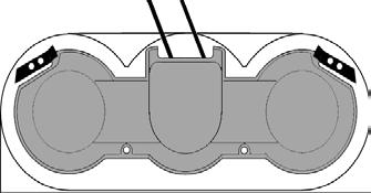
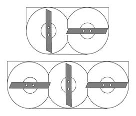
9 ENGLISH EN 5.3 Service position 1. Activate the parking brake. 2. Set the implement lifter in transport position. 3. If the deck has electrical cutting height adjustment, disconnect the cable from the machine. See fig Combi Pro, 107 M HD, 107 M: Set the highest cutting height. 121 M: Set the cutting height in the centre position Combi Pro: Remove pins and washers. See fig M HD: Remove pins and washers. See fig M: Lift up the rear section of the cutting deck, undo the catches (12:L) and lower. 121 M: Disconnect the rear section of the cutting deck by removing the pins (7:I). 6. Remove the belt cover. See fig. 5:E, 8 and 10. The number in the figure indicates the key width. 7. Only 125 Combi Pro: Remove the belt guide (5:F). 8. Grip the belt tensioner s lever with your left hand. Pull the lever and unhook the tensioner from the belt with your right hand. See fig Force the belt off the deck s pulley. 10.Grip the front edge of the deck and lift up. Lift until the deck is completely vertical and rest the rear edge on the floor. See fig. 20. Reset 125 Combi Pro in accordance with 3.1. Reset 107 M HD in accordance with 3.2. Reset 107 M in accordance with 3.3. Reset 121 M in accordance with Cleaning The underside of the deck must be cleaned after each use. Set the deck in washing position. Clean the underside of the deck carefully. Use a high-pressure washer, scraper and/or brush. When the surfaces are completely dry and clean, touch up the paintwork. Use durable yellow paint intended for metal outdoors. 5.5 Wheels 125 Combi Pro is fitted with two lubricating cups (21:M) for the vertical shafts. 107 M HD is fitted with two lubricating cups for the vertical shafts (21:M) and two lubricating cups (21:N) for the wheel axles. The grease nipples must be lubricated with universal grease after 50 hours of operation. 5.6 Replacing blades Wear protective gloves when changing blade(s) to avoid cutting yourself. Check that the blades are always sharp. This produces the best cutting results. Always check the blade(s) after a collision. If the blade system has been damaged, defective parts should be replaced. Always use genuine spare parts. Nongenuine spare parts can entail a risk of injury, even if they fit the machine. The deck is equipped with blades according to the following alternatives: Separate blades, screwed into place on the blade bars. See fig. 22. Full blade. See fig Separate blades The blades are replaceable. When replacing, both blades on the same blade bar must be replaced to avoid imbalance. Tightening torque: Screws (22:P) - 24 Nm Shear bolts (22:Q) Nm In the event of a collision, the shear bolts (22:Q) can break and the blades bend back. If this has happened, install genuine shear bolts and tighten as above Full blade, fig. 23 The full blade is replaced when the edges are worn. Install the new blade with the punched text facing down. Tightening torque: 24 Nm. 5.7 Synchronising, blades The following decks have synchronised blades: 107 M 107 M HD 121 M If one of the blades has struck a solid object (e.g. a stone), the positive drive belt may mesh incorrectly, endangering the synchronisation. This entails a risk of the blades colliding with each other. Correctly synchronised blades must be offset 90 from each other. See fig. 24. Always check synchronisation after a collision. If there is any suspicion of incorrect synchronisation, contact an authorised Stiga workshop for repair work to be carried out. The blades in the 125 Combi Pro are freely rotating.
10 EN ENGLISH 6 SPARE PARTS STIGA genuine spare parts and accessories are designed specifically for STIGA machines. Please note that non-genuine spare parts and accessories have not been checked or approved by STIGA: The use of such parts and accessories can affect the function and safety of the machine. STIGA accepts no responsibility for damage or injuries caused by such products. 7 DESIGN REGISTRATION This product or parts thereof is covered by the following design registration: Sweden: Germany: France: , USA: GGP reserves the right to make alterations to the product without prior notification.
11 GGP Sweden AB Box 1006 SE TRANÅS
D 5b. 1. Park a. 6b. Park Park a. Park Park Park -1993
 STIGA PARK 121 M 1. Park -1993 5a. D 5b. 2. Park -1993 6a. Park -1999 6b. Park 2000- F G H 3. Park -1993 7. I I 4. Park -1993 8. 2 J 9. 13. 10. 14. Z X Y W V 11. 15. Denna produkt, eller delar därav, omfattas
STIGA VILLA VILLA 12 VILLA 14 HST VILLA 16 HST
 STIGA VILLA VILLA 12 VILLA 14 HST VILLA 16 HST BRUKSANVISNING KÄYTTÖOHJEET BRUGSANVISNING BRUKSANVISNING GEBRAUCHSANWEISUNG INSTRUCTIONS FOR USE MODE D EMPLOI GEBRUIKSAANWIJZING SV...5 FI...12 DA..19 NO.27
Mountfield. Princess Lawnmower Owner s Manual
 DEUTSCH D Princess Lawnmower Owner s Manual 8211-0408-01 GB ENGLISH SAFETY INSTRUCTIONS SYMBOLS The following symbols can be found on the machine to remind you of the care and attention that are required
STIGA DINO 45 EURO TORNADO
 STIGA DINO 45 EURO TORNADO 45 8211-3389-08 SVENSKA S 1. 2. 1 2 3 4 3. 4. FULL ADD ADD FULL 5. 6. STOP G G 7. 8. EURO 2 S SVENSKA 3 2 1 3x 9. 10. 0,76 mm 0,75 mm 11. 12. 40 Nm 13. 3 SVENSKA S 4 GB ENGLISH
STIGA TORNADO 51 S 51 SE PRO 51 S
 STIGA TORNADO 51 S 51 SE PRO 51 S 8211-0225-09 SVENSKA S 1 2 3 1. 2. ADD FULL FULL ADD ADD FULL 0,15 l. 3. LS 45 4. XTE 60 3x 5. LS 45 6. XTE 60 STOP I H 7. 8. 2 S SVENSKA 9. 10. 11. 12. LS 45 0,75 mm
Mountfield El 33 Lawnmower Owner s Manual
 DEUTSCH D Mountfield El 33 Lawnmower Owner s Manual 811-0400-01 S SVENSKA 4 1 3 1 = 0 mm = 30 mm 3 = 40 mm 4 = 50 mm 1 130 mm 4 3 3. 160 mm 1 A C B 1. 4. 1 8 4 3 5 9. SVENSKA S 5. 6.. 3 STOP SAFETY INSTRUCTIONS
STIGA PARK 4WD PRO 25 PRO 20 PRO 16. PRO Svan
 STIGA PARK 4WD PRO 25 PRO 20 PRO 16 PRO Svan BRUKSANVISNING KÄYTTÖOHJEET BRUGSANVISNING BRUKSANVISNING GEBRAUCHSANWEISUNG INSTRUCTIONS FOR USE MODE D EMPLOI GEBRUIKSAANWIJZING SV...8 FI...19 DA..30 NO.41
Parts Catalogue EL 340. for model
 Parts Catalogue for model EL 40 The contents described in the parts list may change due to improvement. The drawings of the spare parts are only indicative and might not represent the part in question
Wheel Horse. 42 Mower. for Lawn and Garden Tractors. Model No & Up. Operator s Manual
 FORM NO. 9 559 Rev A Wheel Horse 4 Mower for Lawn and Garden Tractors Model No. 78 890000 & Up Operator s Manual IMPORTANT: Read this manual carefully. It contains information about your safety and the
Spareparts COMBI 53 SQ. Model Year 2012
 COMBI 53 SQ Model Year 202 Use GLOBAL GARDEN PRODUCT Genuine Spare Parts specified in the parts list for repair and/or replacement. The contents described in the parts list may change due to improvement.
Kubota Rear Discharge Mowers 1.3m
 Operating instructions and parts manual for Kubota Rear Discharge Mowers 1.3m (For G2160 Tractors) autoguide equipment Heddington, Nr Calne, Wiltshire, SN11 0PS Telephone: +44 (0) 1380 850885 Fax: +44
48 Side Discharge Mower
 FORM NO. 9 7GB Wheel Horse 48 Side Discharge Mower for Lawn & Garden Tractors Model No. 7868 790000 & Up Operator s Manual IMPORTANT: Read this manual carefully. It contains information about your safety
GROUNDSMASTER. 52 Recycler. for 120 Traction Unit. Model No & UP. Operator s Manual
 FORM NO. 8-980 Rev A GROUNDSMASTER 5 Recycler for 0 Traction Unit Model No. 077 79000 & UP Operator s Manual IMPORTANT: Read this manual carefully. It contains information about your safety and the safety
Wheel Horse. 52 Mowers. Model No & Up Model No & Up. Operator s Manual
 FORM NO. 9-567 Wheel Horse 5 Mowers for Lawn & Garden Tractors Model No. 7880 890000 & Up Model No. 7885 890000 & Up Operator s Manual IMPORTANT: Read this manual carefully. It contains information about
LWA STIGA DINO. Model:... Type:... (Year)... S/N...
... S/N...") STIGA DINO Model:................ Type:........... (Year)....... S/N................ LWA db BRUKSANVISNING KÄYTTÖOHJEET BRUGSANVISNING BRUKSANVISNING GEBRAUCHSANWEISUNG INSTRUCTIONS FOR USE MODE D EMPLOI
STIGA DINO Model:................ Type:........... (Year)....... S/N................ LWA db BRUKSANVISNING KÄYTTÖOHJEET BRUGSANVISNING BRUKSANVISNING GEBRAUCHSANWEISUNG INSTRUCTIONS FOR USE MODE D EMPLOI
Form No Wheel Horse. 52 in. Mower 5xi Tractor Attachment. Model No and Up. Operator s Manual. Domestic English (EN)
") Form No. -50 Wheel Horse 5 in. Mower 5xi Tractor Attachment Model No. 7870 0000000 and Up Operator s Manual Domestic English (EN) Contents Page Introduction................................ Safety and Instruction
Form No. -50 Wheel Horse 5 in. Mower 5xi Tractor Attachment Model No. 7870 0000000 and Up Operator s Manual Domestic English (EN) Contents Page Introduction................................ Safety and Instruction
ProLine. 44 Mower. for 120 Traction Unit. Model No & Up. Operator s Manual
 FORM NO. 9 ProLine Mower for 0 Traction Unit Model No. 05 99000 & Up Operator s Manual IMPORTANT: Read this manual carefully. It contains information about your safety and the safety of others. Also become
Wheel Horse. 48 Mower. for Lawn and Garden Tractors. Model No & Up. Operator s Manual
 FORM NO. 5 Wheel Horse 48 Mower for Lawn and Garden Tractors Model No. 786 990000 & Up Operator s Manual IMPORTANT: Read this manual carefully. It contains information about your safety and the safety
Mountfield M Series Lawnmower Owner s Manual
 DEUTSCH D Mountfield M Series Lawnmower Owner s Manual 8211-0401-03 S SVENSKA B 1. 2. 3. 4. F D E 5. 6. 7. 2 SVENSKA S ADD FULL 0,15 l. 8. Briggs & Stratton 9. Honda FULL/MAX ADD/MIN 10. Briggs & Stratton
36 Rear Discharge Mower
 FORM NO. 8 95 Rev. A Wheel Horse 6 Rear Discharge Mower for Classic Garden Tractor Model No. 7805 790000 & Up Operator s Manual IMPORTANT: Read this manual carefully. It contains information about your
44 and 52 Twin Bagger 100 Series Z Master
 Form No. 7 87 and 5 Twin Bagger 00 Series Z Master Model No. 7855 Serial No. 000000 and Up Operator s Manual English (CE) Contents Page Introduction................................ Safety.....................................
CRC-CSC 534 W - CRC-CSC 534 WQ
 Parts Catalogue for model CRC-CSC 534 W - CRC-CSC 534 WQ Use GLOBAL GARDEN PRODUCT Genuine Spare Parts specified in the parts list for repair and/or replacement. The contents described in the parts list
Edition Manual Chapter Page Workshop Manual, Stiga Park 5 Belts 11
 2008-05-19 Workshop Manual, Stiga Park 5 Belts 11 Pro 20 1. Dismantle the belts A and B as described above. 2. Block up the rear frame and remove the right rear wheel. Clean carefully the insex hole in
Wheel Horse. 48 Mower. for 5xi Tractors. Model No & Up. Operator s Manual
 FORM NO. 9 Wheel Horse 48 Mower for 5xi Tractors Model No. 786 990000 & Up Operator s Manual IMPORTANT: Read this manual, and your tractor manual, carefully. They contain information about your safety
Operating Instructions
 Please Read These Instructions Before Using Your Mower Operating Instructions for model HP470 & SP470 Lawnmowers with Briggs & Stratton engine Product Codes: 99646/BQ 97646/BQ Call our Helpline if you
M. E. Y. EQUIPMENT MOWER MANUAL
 M. E. Y. EQUIPMENT MOWER MANUAL 200 COLLIER ROAD, BAYSWATER. WESTERN AUSTRALIA 6053 TELEPHONE (08) 9370 1110, FACSIMILE (08) 9370 2566 Web Site: www.mey.com.au Email: info@mey.com.au INTRODUCTION The technical
CRL-CSL 484 WS - CRL-CSL 484 WSQ
 Parts Catalogue for model CRL-CSL 484 WS - CRL-CSL 484 WSQ Use GLOBAL GARDEN PRODUCT Genuine Spare Parts specified in the parts list for repair and/or replacement. The contents described in the parts list
TO THE OWNER ASSEMBLY
 TO THE OWNER This is an operational and general maintenance manual only and does not cover repair. All repair work must be performed by an authorized BOLENS DEALER or the factory warranty is void. Bolens
Z Master. 62 Mower. for Z Master Z 255 Traction Unit. Model No & UP. Operator s Manual
 FORM NO. 9 88 Z Master 6 Mower for Z Master Z 55 Traction Unit Model No. 7408 89000 & UP Operator s Manual IMPORTANT: Read this manual carefully. It contains information about your safety and the safety
KING COBRA/CALIBER GRASS COLLECTION SYSTEM PARTS & OPERATORS MANUAL
 KING COBRA/CALIBER GRASS COLLECTION SYSTEM PARTS & OPERATORS MANUAL GRASS CATCHER W/WEIGHTS: TUBE KITS: BLOWER KITS: 52 542128 52 542119 5101002 60 542129 60 542120 5101003 2 WORLDLAWN POWER EQUIPMENT
ProLine. 36 Mower. for Mid-Size Traction Unit. Model No & Up. Operator s Manual
 FORM NO. 8 77 Rev A ProLine 6 Mower for Mid-Size Traction Unit Model No. 05 79000 & Up Operator s Manual IMPORTANT: Read this manual carefully. It contains information about your safety and the safety
Service Manual. Tiltrotator/Rotator EC/ECR The noble art of digging. Version 1.0
 Service Manual Tiltrotator/Rotator EC/ECR10 30 The noble art of digging Version 1.0 Table of contents Safety regulations General information...4 Cautions...4 Technical data General information...6 Tightening...7
Service Manual. Tiltrotator/Rotator EC/ECR05. The noble art of digging. Version 1.0
 Service Manual Tiltrotator/Rotator EC/ECR05 The noble art of digging Version 1.0 Table of contents Safety regulations General information......4 Cautions...4 Technical data General information...6 Tightening...7
ATTACHMENTS COMPONENT LOCATION
 42-Inch Mower Deck ATTACHMENTS COMPONENT LOCATION C D E F G H I H G M A B J O K L N M J A - Gage Wheel (Left Front) B - Belt Cover C - Primary Drive Belt D - Flat Idler (fixed) E - Gage Wheel (Right Front)
STIGA COMPACT LINE SNOW REX SNOW BREEZE
 STIGA COMPACT LINE SNOW REX SNOW BREEZE BRUKSANVISNING KÄYTTÖOHJEET BRUGSANVISNING BRUKSANVISNING GEBRAUCHSANWEISUNG INSTRUCTIONS FOR USE MODE D EMPLOI ISTRUZIONI PER L USO INSTRUKCJA OBS UGI»HC P K»fl
Quiet Collector. Model No & Up
 FORM NO. -0 Quiet Collector Model No. 79-990000 & Up Operator s Manual IMPORTANT: Read this manual, and your tractor manual, carefully. They contain information about your safety and the safety of others.
GRASS CATCHER PART S & OPERATORS MANUAL
 GRASS CATCHER PART S & OPERATORS MANUAL WORLDLAWN POWER EQUIPMENT, INC. WORLDLAWN.COM 2415 ASHLAND AVE BEATRICE, NE 68310 800-267-4255 FAX 402-223-4103 2 3 4 OPERATORS MANUAL This catcher manual is for
Parts Catalogue NT 480 W WQ. for model
 Parts Catalogue for model NT 480 W - 480 WQ Use GLOBAL GARDEN PRODUCT Genuine Spare Parts specified in the parts list for repair and/or replacement. The contents described in the parts list may change
Wheel Horse. 44 Snowthrower. for 5xi Lawn and Garden Tractors. Model No & Up. Operator s Manual
 FORM NO. 8 Rev A Wheel Horse Snowthrower for 5xi Lawn and Garden Tractors Model No. 7966 890050 & Up Operator s Manual IMPORTANT: Read this manual, and your tractor manual, carefully. They contain information
BrentChalmers.com. Owner Operation and Maintenance Manual ROTARY MOWER MODEL WISCONSIN,U.S.A. PORT ATTACHMENT 28 INCH WASHI~GTON,
 ROTARY MOWER Owner Operation and Maintenance Manual ATTACHMENT 28 INCH MODEL 15100-01 (2) Do not allow children to operate powered equipment at any time. The average child is not capable of coping with
Berta Flail Mower Attachment. BCS Power Units
 Manufactured by Berta s.r.l. to fit BCS Power Units Operating Instructions Before commissioning the machine, read operating instructions and observe warning and safety instructions. PLEASE ALSO READ ORIGINAL
48 Side Discharge Mower
 FORM NO. 9 650 Rev A Wheel Horse 8 Side Discharge Mower for Classic Garden Tractor Model No. 786 890000 & Up Operator s Manual IMPORTANT: Read this manual carefully. It contains information about your
OPERATIONAL ADVICE WARNING: TO PREVENT SERIOUS INJURY, PLEASE READ AND UNDERSTAND ALL WARNINGS AND INSTRUCTIONS BEFORE USE.
 OPERATIONAL ADVICE WARNING: TO PREVENT SERIOUS INJURY, PLEASE READ AND UNDERSTAND ALL WARNINGS AND INSTRUCTIONS BEFORE USE. SAVE THIS MANUAL Keep this manual in a safe place for future reference. This
Parts Catalogue CR-CS 480 W - CR-CS 480 WQ. for model
 Parts Catalogue for model CR-CS 480 W - CR-CS 480 WQ Use GLOBAL GARDEN PRODUCT Genuine Spare Parts specified in the parts list for repair and/or replacement. The contents described in the parts list may
Worldlawn Power Equipment, Inc. Industrial Park 2415 Ashland Ave. Beatrice, NE Toll Free Number:
 Operator s Manual R WYZ48/52/60CS BAGGER Worldlawn Power Equipment, Inc. Industrial Park 2415 Ashland Ave. Beatrice, NE 68310 Toll Free Number: 1-800-267-4255 OPERATOR S MANUAL This catcher manual is for
TURBO 55 S COMBI (2006) [ ] TURBO 55 S COMBI - RV Lawn mowers-combi Documents
![TURBO 55 S COMBI (2006) [ ] TURBO 55 S COMBI - RV Lawn mowers-combi Documents](/thumbs/84/89739686.jpg "TURBO 55 S COMBI (2006) [ ] TURBO 55 S COMBI - RV Lawn mowers-combi Documents") TURBO 55 S COMBI - RV 65-12-9230-21-Lawn mowers-combi Documents Deck And Height Adjusting Handle, Lower Part Handle, Upper Part Controls Technical information Article number 12-9230-21 Season 2005-2006
TURBO 55 S COMBI - RV 65-12-9230-21-Lawn mowers-combi Documents Deck And Height Adjusting Handle, Lower Part Handle, Upper Part Controls Technical information Article number 12-9230-21 Season 2005-2006
Side Discharge Chute Oil Filler & Dipstick Silencer/Exhaust
 1 SPECIFICATION Electric Start Engine - Size 6HP Engine speed 2850rpm Metal Deck Cutting width 550mm (22 ) Adjustable cutting height 7 Grass collection capacity 60L Gross weight 41Kg Fuel type Unleaded
Quiet Collector. Model No & Up
 FORM NO. -8GB Rev A Quiet Collector Model No. 795-890000 & Up Operator s Manual IMPORTANT: Read this manual, and your tractor manual, carefully. They contain information about your safety and the safety
36 Tiller Wheel Horse Lawn and Garden Tractor Attachment
 Form No. 9 6 Rev B 6 Tiller Wheel Horse Lawn and Garden Tractor Attachment Model No. 797 890000 and Up Operator s Manual English(En) Contents Page Introduction................................ Safety.....................................
WORKSHOP MANUAL. Garden Tractor: EF 95 - EF EF OM 95 - OM OM 125
 WORKSHOP MANUAL Garden Tractor: EF 95 - EF 105 - EF 125 - OM 95 - OM 105 - OM 125 2 Workshop manual 1 Foreword... 5 2 General... 6 2.1 Safety instructions... 6 3 Maintenance and care... 7 3.1 Maintenance
Operating Instructions
 Please Read These Instructions Before Using Your Mower Operating Instructions for SP470 ES Lawnmower with Briggs & Stratton engine Product Code: 99468/BQ Call our Helpline if you have any problems: Helpline
DIAMONDBACK/EDGE GRASS COLLECTION SYSTEM PARTS & OPERATORS MANUAL
 DIAMONDBACK/EDGE GRASS COLLECTION SYSTEM PARTS & OPERATORS MANUAL GRASS CATCHER W/WEIGHT: TUBE KIT: BLOWER KIT: 48 5101305 632093 632078 52 5101305 542119 632074 60 632086 542120 632081 3 WORLDLAWN POWER
Operator's Manual. VC-60 & VC-60 Plus Harper Industries, Inc. 7/03 Part No
 Operator's Manual VC-60 & VC-60 Plus 2003 Harper Industries, Inc. 7/03 Part No. 970066 Thank you for purchasing a Harper/Goossen Verti-Cutter. As with all Harper/Goossen products, the Harper/Goossen Verti-Cutter
OWNER S MANUAL RIDE-ON LAWNMOWER. SUPPLEMENT FOR M SERIES. Part N o :
 RIDE-ON LAWNMOWER OWNER S MANUAL www.masport.com SUPPLEMENT FOR M SERIES IMPORTANT: Keep these instructions and the engine booklet in a safe place for future reference. They contain important information
STIGA COMBI 53 SEQ (2014) /S14. Spare parts list Reservdelar Repuestos Ersatzteile Pièces détachées Reserve onderdelen Catalogo ricambi
 /S14. Spare parts list Reservdelar Repuestos Ersatzteile Pièces détachées Reserve onderdelen Catalogo ricambi") STIGA 299536548/S14 Spare parts list Reservdelar Repuestos Ersatzteile Pièces détachées Reserve onderdelen Catalogo ricambi Use ST. S.p.A. Genuine Spare Parts specified in the parts list for repair and/or
STIGA 299536548/S14 Spare parts list Reservdelar Repuestos Ersatzteile Pièces détachées Reserve onderdelen Catalogo ricambi Use ST. S.p.A. Genuine Spare Parts specified in the parts list for repair and/or
Directions for use VIBRO FLEX 7400
 Directions for use VIBRO FLEX 7400 Contents Introduction... 3 Identification... 3 Explanation of symbols... 4 Safety... 5 General safety advice... 5 Coupling and uncoupling... 5 Three-point hitch or linkage...
STIGA PARK PRO 18 PRO 16 PRESIDENT CLASSIC
 STIGA PARK PRO 18 PRO 16 PRESIDENT CLASSIC 8211-0211-06 7. Park Classic-President 11. 8. Park Pro16-Pro18 12. Park Classic-President 9. Park President 13. Park Pro16-Pro18 10. Park Pro16-Pro18 14. Park
Removing/installing final drive
 1(16) Removing/installing final drive Special tools: 998 5972, 999 5561, 999 5652, 999 5659, 999 5660 Removing Note! Position the rear lifting arms on the arrows on the sills. This is so the support arm
Your G3 buggy is fitted with three switches on the front part of the body:
 CONTENTS Buggy operation... 3 General Maintenance... 5 Technical Maintenance... 6 Front wheel bearing replacement... 6 Rear wheel bearing replacement... 7 Chain replacement... 8 Chain Adjustment... 9 Brake
42 Mower Wheel Horse Classic Garden Tractor Attachment
 Form No. 6 9 Mower Wheel Horse Classic Garden Tractor Attachment Model No. 78 000000 and Up Operator s Manual Domestic English (EN) Contents Page Introduction................................ Slope Chart..............................
48 Mower Wheel Horse Classic Garden Tractor Attachment
 Form No. 6 96 Rev B 8 Mower Wheel Horse Classic Garden Tractor Attachment Model No. 786 000000 and Up Operator s Manual Domestic English (EN) Contents Page Introduction.................................
Mountfield 480 R R Lawnmower Owner s Manual
 DEUTSCH Mountfield 480 R - 550 R Lawnmower Owner s Manual 8211-0403-01 D SVENSKA S B 1. 2. F D E 3. 4. 5. 6. 7. 8. 3 S SVENSKA ADD FULL 0,15 l. 9. 10. G I STOP 11. 12. 13. Y X 14. 0,75 mm 15. 16. 4 SVENSKA
FIELD KIT FITTING INSTRUCTIONS FOR TR3
 24795G-GB (rev.1) FIELD KIT FOR TR3 Rear Roller Brush Kit LMAC185-TR3-F for "Fairway" style Cutting Units Series: AAG, AAH, AAJ, AAK IMPORTANT NOTE - TR3 ONLY Grassboxes cannot be used with these Cutting
Rider Pro 15. Operator s manual Please read these instructions carefully and make sure you understand them before using the machine.
 Rider Pro 15 Operator s manual Please read these instructions carefully and make sure you understand them before using the machine. 101 91 34-26 CONTENTS Operator s Manual for Rider Pro 15 Introduction...
Mountfield 480 R R Lawnmower Owner s Manual
 DEUTSCH D Mountfield 480 R - 550 R Lawnmower Owner s Manual 8211-0403-03 S SVENSKA 1 2 1 2 3 3 4 A B 5 6 7 8 2 SVENSKA 9 10 S 11 12 13 Briggs & Stratton 14 Honda ADD FULL 0,15 l. FULL/MAX ADD/MIN 15 Briggs
Edition Manual Chapter Page Workshop Manual, Stiga Park 4 Hydraulic system 8
 2008-05-19 Workshop Manual, Stiga Park 4 Hydraulic system 8 The charge pump (1) and the main pump (2) are integrated into one unit, the hydraulic pump (C) which is located separat in front of the engine.
Drive Unit e-drive1. Installation instructions 04/2014. English translation of the original German installation instructions
 Drive Unit e-drive1 Installation instructions 04/2014 English translation of the original German installation instructions Contents Foreword... 3 Availability... 3 Structural features in the text... 3
Safety First. Owning Lawn And Garden Equipment Doesn t Have To Cost An Arm And A Leg.
 Safety First Owning Lawn And Garden Equipment Doesn t Have To Cost An Arm And A Leg. When operating equipment... Children should be seen, not hurt. Kids and power equipment do not mix. Do not allow children
Operator s manual. Rider Battery. Please read the operator s manual carefully and make sure you understand the instructions before using the machine.
 Operator s manual Rider Battery Please read the operator s manual carefully and make sure you understand the instructions before using the machine. English KEY TO SYMBOLS Symbols These symbols are on the
m WARNING: READ ALL m WARNING: This unit can be dangerous! Careless or m DANGER: Risk of cut. Keep hands and feet away IMPORTANT! Safety Instructions
 16-Inch Manual Reel Mower with Catcher Model No. MJ500M Form No. SJ-MJ500M-880E A Division of Snow Joe, LLC IMPORTANT! Safety Instructions m WARNING: READ ALL INSTRUCTIONS BEFORE USE. m WARNING: This unit
42in GT Classic Single Stage Snowthrower Conversion Kit XT Series Garden Tractor
 Form No. 9 66 in GT Classic Single Stage Snowthrower Conversion Kit XT Series Garden Tractor Part No. 06 88 Installation Instructions English (EN) This kit is for installing an existing 00 Series Classic
27 Rotary Cutting Deck Groundsmaster 3500 Traction Unit
 Form No. 336-56 7 Rotary Cutting Deck Groundsmaster 3500 Traction Unit Model No. 308 00000 and Up Operator s Manual English (EN) Contents Page Introduction................................ Safety.....................................
52 inch Twin Bagger and Finishing Kit 200 Series Z Master
 Form No. 9 68 inch Twin Bagger and Finishing Kit 00 Series Z Master Model No. 7898 Serial No. 000000 and Up Model No. 780 Operator s Manual English (EN) Contents Page Introduction................................
WHEEL HORSE LAWN TRACTOR
 FORM NO. 897 WHEEL HORSE LAWN TRACTOR FOR AND 8 MOWERS SET-UP INSTRUCTIONS Loose Parts Note: Use the chart below to verify all parts have been shipped. DESCRIPTION QTY. USE Front Wheel Shim Washer (as
Tyres OVERVIEW TYRE PRESSURES
 Tyres OVERVIEW Tyres of the correct type, manufacturer and dimensions, with correct cold inflation pressures are an integral part of every vehicle s design. Regular maintenance of tyres contributes not
Operator's Manual. Please read these instructions carefully and make sure you understand them before using the machine.
 Operator's Manual Please read these instructions carefully and make sure you understand them before using the machine. TABLE OF CONTENTS Operator s manual for FR 2111, FR 2111 M, FR 2113 A, FR 2113 MA,
Copyright 2014 Global Garden Products 2 STIGA - ESTATE 3084 H
 ESTATE 308 H 35 36 37 3 33 32 38 31 39 0 0 30 28 27 26 25 5 6 11 15 20 22 13 1 1 1 23 12 2 2 3 17 16 18 19 5 2 6 Copyright 201 Global Garden Products 2 STIGA - ESTATE 308 H Chassis POS CODE Q.TY DESCRIPTION
Rider 14 Pro. Operator s manual Please read these instructions carefully and make sure you understand them before using the machine.
 Rider 14 Pro Operator s manual Please read these instructions carefully and make sure you understand them before using the machine. 101 90 55-95 Svenska 31 CONTENTS Operator s Manual for Rider 14 Pro Safety
Operator s manual Rider 155. Please read these instructions carefully and make sure you understand them before using the machine.
 Operator s manual Rider 155 Please read these instructions carefully and make sure you understand them before using the machine. English CONTENTS Operator s Manual for Rider 155 Introduction... 2 Driving
Finishing Mower Estate 72
 Finishing Mower Estate 72 Owners/Operators Manual & Spare Parts List Issue Date: October 2011 1 Introduction Your FIELDMASTER Estate 72 Finishing Mower has been designed to do a range of work to your satisfaction.
Kubota Mulching Mower 1.5m (F60 Series)
") Operating instructions and parts manual for Kubota Mulching Mower 1.5m (F60 Series) autoguide equipment Stockley Road, Heddington, Nr Calne, Wiltshire, SN11 0PS England Telephone: +44 (0) 1380 850885 Fax:
Operating instructions and parts manual for Kubota Mulching Mower 1.5m (F60 Series) autoguide equipment Stockley Road, Heddington, Nr Calne, Wiltshire, SN11 0PS England Telephone: +44 (0) 1380 850885 Fax:
CRC-CSC 534 WS - CRC-CSC 534 WSQ
 Parts Catalogue for model CRC-CSC 534 WS - CRC-CSC 534 WSQ The contents described in the parts list may change due to improvement. The drawings of the spare parts are only indicative and might not represent
CRC-CSC 534 WS - CRC-CSC 534 WSQ
 Parts Catalogue for model CRC-CSC 534 WS - CRC-CSC 534 WSQ The contents described in the parts list may change due to improvement. The drawings of the spare parts are only indicative and might not represent
Kubota Mulching Mowers 1.3m
 Operating instructions and parts manual for Kubota Mulching Mowers 1.3m (For G2160 Tractors) autoguide equipment Heddington, Nr Calne, Wiltshire, SN11 0PS Telephone: +44 (0) 1380 850885 Fax: +44 (0) 1380
DFS Vac Collection System 400 Series Z Master
 Form No. 0 DFS Vac Collection System 00 Series Z Master Model No. 780 Serial No. 000000 and Up Operator s Manual Register your product at www.toro.com Original Instructions (EN/GB) Contents Page Introduction................................
42in GT Classic Single Stage Snowthrower Conversion Kit XT Series Garden Tractor
 Form No. 5 70 in GT Classic Single Stage Snowthrower Conversion Kit XT Series Garden Tractor Part No. 06 858 Installation Instructions Original Instructions (EN) This kit is for installing an existing
Final Drive. Cush Drive SelVice Manual- Thunderbird. Inspection Note: Removal. Installation. 1. Remove the rear wheel (see page 76-8>.
 Inspection Note: If the drive belt is to be renewed, always check and if necessary replace the rear belt pulley drive flange bearings. 1. Inspect the drive belt for wear, cracks in the teeth, frayed edges
48CP 48 CORE PLUG LAWN AERATOR Patent Pending
 48CP 48 CORE PLUG LAWN AERATOR Patent Pending READ AND FOLLOW ALL SAFETY RULES AND OPERATING INSTRUCTIONS BEFORE USING THIS EQUIPMENT Assembled in U.S.A. of domestic and imported components 6000203-REV
R190 Lawn Boss 21 (1989) Page 1 of 8 Body Assembly
 Page 1 of 8 Body Assembly") 129-476R190 Lawn Boss 21 (1989) Page 1 of 8 Body Assembly 129-476R190 Lawn Boss 21 (1989) Page 2 of 8 Body Assembly 1 731-0609 1 Control Handle Ass'y. 3 710-0796 1 /P Truss Mach. B-Tap Scr. #12 x 1.5"
129-476R190 Lawn Boss 21 (1989) Page 1 of 8 Body Assembly 129-476R190 Lawn Boss 21 (1989) Page 2 of 8 Body Assembly 1 731-0609 1 Control Handle Ass'y. 3 710-0796 1 /P Truss Mach. B-Tap Scr. #12 x 1.5"
SPARE PARTS LIST RIDERS R112 C5, , 2014
 SPARE PARTS LIST RIDERS R112 C5, 967178501, 2014 CHASSIS REAR R112 C5, 967178501, 2014 CHASSIS REAR R112 C5, 967178501, 2014 Ref Part No Description Remark QTY KIT 1 581 27 41-01 FRAME 1 2 725 24 59-61
BAD BOY GRASS BAGGING SYSTEM
 BAD BOY GRASS BAGGING SYSTEM TABLE OF CONTENTS WILL FIT ALL 2019 OUTLAW SERIES MOWERS SAFETY RULES AND INFORMATION.. 2 GENERAL OPERATION.... 3 WARRANTY INFORMATION.... 5 INSTALLATION INSTRUCTIONS.. 6 PAGE
Operating instructions Assembly instructions
 MOBILITY MADE SIMPLE! Adapter & Adaptation Operating Instructions Operating instructions Assembly instructions Adapter & adaptation for NJ1 e-assistant, NJ1 adaptive bike, SPIKE adaptive bike and FREEWAY
Wheel Horse 48 Blade for 5xi Garden Tractors
 Form No. -9 Wheel Horse 8 Blade for 5xi Garden Tractors Model 7955 0000000 Operator s Manual Domestic English (EN) Contents Page Introduction................................ Installation.................................
SPARE PARTS LIST RIDERS RIDER 111 B, , , , ,
 SPARE PARTS LIST RIDERS RIDER 111 B, 965996801, 965996885, 966663185, 967186501, 2011-02 CHASSIS & ENCLOSURES RIDER 111 B, 965996801, 965996885, 966663185, 967186501, 2011-02 CHASSIS & ENCLOSURES RIDER
Operator s manual. Please read the operator s manual carefully and make sure you understand the instructions before using the machine.
 R 422Ts Operator s manual R 422Ts AWD Please read the operator s manual carefully and make sure you understand the instructions before using the machine. English CONTENTS Contents CONTENTS Contents...
OPERATING INSTRUCTIONS ELECTRIC LAWNMOWER MODEL : LSM 1200 EL
 OPERATING INSTRUCTIONS ELECTRIC LAWNMOWER MODEL : LSM 1200 EL Thank you for purchasing the Lawn Star Lawnmower which is one of the finest and most advanced lawnmowers today s technology can produce. Before
Operator s manual Rider Pro 15. Please read these instructions carefully and make sure you understand them before using the machine.
 Operator s manual Rider Pro 15 Please read these instructions carefully and make sure you understand them before using the machine. English Svenska 31 CONTENTS Operator s Manual for Rider Pro 15 Introduction...
The information in this operator s manual is limited in application to the Honda mulching kit for Honda H4000 Series lawn tractors with 42 and 46
 The information in this operator s manual is limited in application to the Honda mulching kit for Honda H4000 Series lawn tractors with 42 and 46 mower decks. Before installing or operating this equipment,
HYDRAULICS. TX420 & & lower. Hydraulic Tandem Pump Removal. 4. Remove the LH side panel (Fig. 0388).
.") TX420 & 425 240000299 & lower 4. Remove the LH side panel (Fig. 0388). Hydraulic Tandem Pump Removal Note: Cleanliness is a key factor in a successful repair of any hydraulic system. Thoroughly clean all
TX420 & 425 240000299 & lower 4. Remove the LH side panel (Fig. 0388). Hydraulic Tandem Pump Removal Note: Cleanliness is a key factor in a successful repair of any hydraulic system. Thoroughly clean all
OPERATOR S MANUAL CUSTOMER SERVICE CHECKBOOK
 OPERATOR S MANUAL CUSTOMER SERVICE CHECKBOOK Valid for e-max versions: English Status as of January 2008 1 Dear e-max riders, We are pleased that you have chosen one of our brand name vehicles and we welcome