E L L I O T T 14M, 18M & 24M. Contents OPERATORS INSTRUCTION HANDBOOK FOR THE HIGH SPEED SHAPING MACHINES MODELS. Also COMPONENT PARTS LIST.
|
|
|
- Clemence Warner
- 5 years ago
- Views:
Transcription
1 OPERATORS INSTRUCTION HANDBOOK FOR THE E L L I O T T HIGH SPEED SHAPING MACHINES MODELS 14M, 18M & 24M Also COMPONENT PARTS LIST Contents Page Slinging 2 Examination 2 Cleaning 2 Installation 3 Foundation 4 Lubrication 5 Operating instructions 8 Wiring 10 Maintenance 10 Extra equipment 12 Specification 16

2 Slinging In order not to disturb the alignment of the machine, care is required when lifting, and the method shown in figure 1 should be employed. Examination The machine should be carefully examined on arrival and any damage sustained in transit reported immediately to the responsible authority. Cleaning All bright surfaces are covered with a rust preventative which is soluble in ordinary machine oil. Do not allow the sliding members to be moved until all the protective material has been removed and
3 use only lubricating oil for this purpose. Installation Figure 2 shows the Foundation Plan which gives all the required dimensions for installation. In order to ensure accurate and efficient operation, the machine should be correctly levelled and bolted to a good concrete foundation. Before levelling, a swivel table should be clocked square with the top surface of the cross slide. A precision level should be used for levelling the machine using the top surface of the main slide for transverse levelling, and the table top for fore and aft levelling. During levelling, the table support bolts should be released, and the table cross transversed its own width either side of the ram centre line and also vertically transversed. A clock should be used to check table alignments with the ram. The machine should first be levelled at four positions by packings or wedges local to the rear foundation bolts and the front vertical vee slide. The front of the base should now be supported by feeling in two wedges or packings local to the front foundation bolts, and two beneath the table support. The foundation bolts should now be tightened sown, careful correction being made where necessary to maintain the level. Two packings or wedges should then be carefully inserted, one on each side beneath the centre of the machine body to give support, and the machine grouted in after a final check of all levels has been made. 3
4 4
5 Lubrication Before running, it will be necessary to fill the gear box with a suitable oil to a level half way up the oil level window, the gears and ball bearings on which the gear shafts run are automatically oiled by splash, and it is only necessary to maintain the level as indicated above. The automatic feed gearing, links, etc. should be oiled and the bull wheel bearing oil well refilled each day, and the oil cups and ball oilers that lubricate the slides should be replenished frequently whilst the machine is running. The inspection cover at the side of the main body should be removed once daily in order to lubricate the crank block slides and pivot bearing. Ref. No. Parts Lubricated Lubrication Instructions and Location 1 Gearbox and Intermediate gear Remove plug to maintain oil level oh indicator. The oil should be changed at least twice a year. 2 Gearbox pulley shaft and bearings Tecalemit lubricator provided. 3 Motor Spindle Grease nipple provided 4 Rocking arm die Remove door and (upper) oil through hole in 5 Rocking arm die (lower) rocking arm Fill wickfeed lubricator on rocking arm feed pipe 6 Rocking arm spindle Oil through top of ram to oil hole in bracket 7 Tool head feed screw and slide Oil screw and slide. Lower tool head to ensure complete lubrication 8 Vice slide Oil guideways with vice open an traverse slide to ensure complete lubrication Lubricant Shell Oil Vitrea 69 or equivalent Shell Oil Vitrea 69 or equivalent Shell grease Alvania 2 Shell Oil Vitrea 33 or equivalent Shell Oil Vitrea 33 or equivalent Shell Oil Vitrea 33 or equivalent Shell Oil Vitrea 33 or equivalent Shell Oil Vitrea 33 or equivalent Period Maintain level. Change oil twice yearly. More often if discoloured or dirty. Periodically Periodically
6 9 Main slide and cross slide 10 Table elevating screw Oil slides and traverse. Elevate table to ensure complete lubrication Oil at maximum elevation and lower to ensure complete lubrication 11 Bull gear bearing Remove plug and maintain oil level Shell Oil Vitrea 33 or equivalent Shell Oil Vitrea 33 or equivalent Shell Oil Vitrea 33 or equivalent Ref. No. Parts Lubricated Lubrication Instructions and Location 13 Self act Grease at nipples provided 14 Self act bracket Grease at nipples 15 Self act bracket and ratchet 16 Cross traverse screw provided Bennet flush fitting lubricator provided. Oil ratchet assembly locally Oil through holes in main slide. Oil screw and traverse table to ensure complete lubrication Lubricant Shell oil Vitrea 33 or equivalent Shell oil Vitrea 33 or equivalent Shell oil Vitrea 33 or equivalent Shell oil Vitrea 33 or equivalent 17 Ram guides Main oil level in oil wells Shell oil Vitrea 33 or equivalent 18 Table support slide Clean and oil Shell oil Vitrea 33 or equivalent 19 Vice screw Oil and traverse to Shell oil Vitrea 33 or ensure complete equivalent lubrication 20 Elevating screw bevel gears Move table over to extreme position away from operator. Oil through central holes in main slide and grease bevel gears 21 Bull gear Remove door and grease teeth 22 Stroke adjusting spindle, bevel gears and slide Remove door and oil spindle through oil hole in bull gear. Grease bevel gears and oil slide with oil can Shell oil Vitrea 33 and Shell Grease Alvania 2 or equivalent Shell grease Alvania 2 or equivalent Shell oil Vitrea22 and Shell grease Alvania 2 or equivalent Period Oil daily Grease Periodically Periodically Periodically

7 23 Clutch fork Hinge back clutch cover and oil dies etc. through hole in fork Shell oil Vitrea 33 or equivalent No. Lubricated And Location AUTOMATIC DOWN FEED MACHINES ONLY Shell Oil Vitrea Bevel spindles Oil through oil or equivalent holes in ram 25 Bevel gears Pull ram forward Shell grease and grease from Alvania 2 or underneath equivalent 26 Bevel gears Elevate tool head to maximum and grease from front 27 Ratchet Feed Assembly Oil locally with oil can Shell grease Alvania 2 or equivalent Shell Oil Vitrea 33 or equivalent Periodically Periodically
8 Operating Instructions The power, except for single pulley drive machine, is supplied by a standard electric motor mounted at the back of the main body. The drive is transmitted to the gearbox by vee belts through a Matrix multiple disc friction clutch, operated by lever A. Figure 4. Six speeds are selected by means of the two levers B & C. The length of stroke is adjusted by rotation of the shaft D, after releasing the knurled locknut, and we advise that it should be done with the ram stationary. Setting the stroke length and positioning of stroke should be effected as follows: - Slacken off the clamp E and inch by means of the clutch lever observing the length of stroke as shown by the scale and pointer. Lengthen or shorten to the required stroke in the manner described above and re-check by further inching finally stopping the pointer at its extreme forward position, i.e. with the pointer as near to the tool post as the stroke carries it. Push the ram forward by hand until the tool is as far forward as required and lock in that position with clamp E. Check length and position of stroke by inching. The machine may now be set in motion with the knowledge that the tool will not overrun the travel intended. The vertical feed of the tool post is controlled by handle J, whilst angular fed may be obtained by swivelling the head after unlocking the square headed bolt on models 14M and 18M and the two nuts on Model 24M. The tool angle only may be varied by unlocking the square headed bolt immediately above the tool holder. Manual adjustment of the cross and vertical table movements
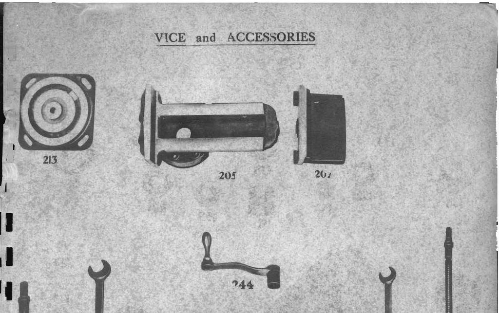
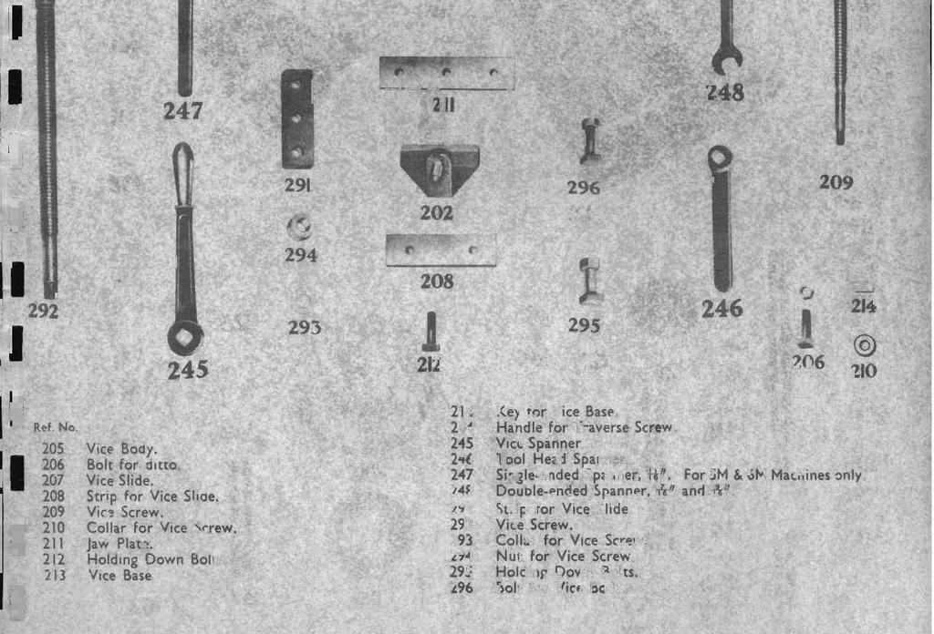
 screw F Slotted feed disc P Tool head gib adjusting nuts G Cross traverse screw R A,D,F engaging handle H Vertical traverse screw J Tool head screw AUTO FEED The")
9 Clutch lever K Auto down feed A plunger B Gear change lever L Auto down feed adjusting screw C Gear change lever M Gib lock bolts D Length of stroke adjustment N Gib adjusting studs E Position of stroke lock O Table gib (tapered) screw F Slotted feed disc P Tool head gib adjusting nuts G Cross traverse screw R A,D,F engaging handle H Vertical traverse screw J Tool head screw AUTO FEED The slotted disc F provides four rates of automatic cross feed. When the feed drive arm is anchored at the outer position on the slotted disc, the largest feed of.0417 per stroke is obtained. Alternatively minimum feed is obtained at the centre of the disc. When the automatic cross feed is not required lift and half turn the plunger in the ratchet mechanism at the end of the cross slide. The auto feed to the apron must be applied at the correct time relative to the ram position, i.e at the back of stroke, and this may be altered to suit the direction of feed by shifting the throw of the feed
 Reversing the ratchet plunger to feed from right to left on this setting will have")
10 actuating link from one side of the slotted disc to the other. The illustraion Fig.5 page 10, shows the feed set correctly for the apron feeding from left to right (looking from front of the machine) Reversing the ratchet plunger to feed from right to left on this setting will have the effect of applying the feed in the middle of the stroke with the subsequent possibility of shearing the safety shear pin. Wiring The wiring diagram fro the machine is shown in Figure 6. The contactor is mounted inside the body of the machine and is accessible through the door on the left side of the machine, the base plate only being visible from the outside. Remote control buttons Start and Stop are Mounted conveniently high up the operating side the machine. Maintenance All slides are fitted with gibs adjustable for wear. Adjustment to the ram and cross slide
11 Gibs is effected by the hexagon headed bolts M holding them in position together with the setting studs N at the side of the gibs. Make sure that the lock nuts on the setting screws are secure after adjustment has been made. The table slide is fitted with a tapered gib which is adjusted by the screw 0 at the operating side of the cross slide. The tool slide gib is adjusted by the screws and lock nuts P. End play in the... To tension the initial drive V belts, unlock the 4 motor flxink bolts and slide motor downwards over motor plate. Reclamp motor in the new position. SAFETY SHEAR PIN. The cross feed mechanism is protected from overload or overrun by means of a shear pin fitted in the feed ratchet arrangement. If the pin shears, replace by proceeding as follows: - Referring to the illustration below: 1 Draw out the sheared portion of the pin from the drive collar. 2 Rotate the cross traverse screw to bring the pin hole in the drive collar in line with the clearance slot on the underside of the ratchet plunger housing. 3 Insert the replacement pin into the drive collar 4 Rotate ratchet, at the same time applying pressure on the pin until the pin hole in the ratchet is located. 5 Push pin into the ratchet, this will drive out the sheared half of the old pin into the clearance slot of the plunger housing.
 fitted at the side of the ram is engaged by giving half a turn to handle B (Fig.7) at the top of the ram.")
12 Extra equipment AUTOMATIC DOWN FEED Automatic down feed to the tool head can be supplied on all machines, but must be specically ordered with the machine. Automatic feed is applied by a plunger and ratchet mechanism A (Fig.7) fitted at the side of the ram is engaged by giving half a turn to handle B (Fig.7) at the top of the ram. The feed increment may be varied by adjusting the height of the trip lever by

13 means of the knurled screw C.

14 Swivelling table incorporating a special support can be supplied on all machines if specially ordered with the machine. The amount of swivel is 45 in either direction and can be locked in position by three clamps at the front of the table. TILTING TABLE TOP This accessory, which can be supplied separately, is quickly mounted on the top surface of the table and is very useful item of additional equipment when used in conjunction with the swivelling table. SLOTTING ATTACHMENT (model 14M 14 stroke machines only ) To fit the attachment, first remove the ram by removing gib and locking nut E (Fig.4) and lifting ram clear. Remove rocking bracket by lifting clear between the ram ways. Remove die block from spigot. Place slotting attachment body in ram ways as shown in Fig. 10 and slip connecting rod end over die block spigot on bull gear. Open inspection cover in attachment body and link connecting rod to
 after releasing the knurled locknut.")

15 slotter ram. The length of stroke may be varied by rotating shaft D (Fig.4) after releasing the knurled locknut. KEYWAY CUTTER HOLDER The keyway cutter holder is clamped in the clapper box in place of the standard tool holder, as illustrated in Fig. 11 and is used for internal shaping, keyway
16 cutting and general work that is difficult to reach with the standard holder. SPECIFICATION 14M 18M 24M Section of tool max 3/8 x 9/16 3/8 x 9/16 ½ x 5/8 Distance, back of tool 5 1/ /16 to clapper box face Diameter of holders ¾ ¾ 1 Component Parts List
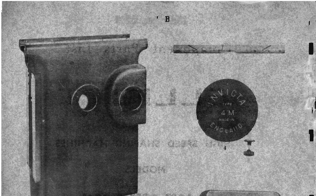
17 E L L I O T T HIGH SPEED SHAPING MACHINES MODELS 14M, 18M & 24M NOTE The parts shown in this book are finished parts and for idenfications purposes only. In some cases it is necessary for the individual part to be correctly fitted to the machine. Please always supply machine serial number when ordering spare parts. E L L I O T M A C H I N E T O O L S L I M I T E D Victoria Road, London, N W 10 Telephone Telegrams: Elliottona London N.W.10 Telex

18

19
20
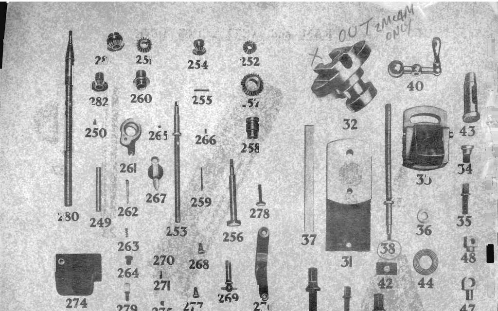
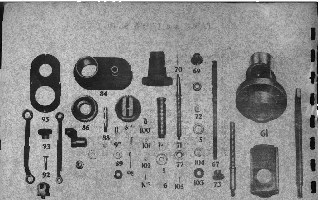
21 Ref. No. 28 Screw for Bracket. 31 Toolbox Slide. 32 Swivel Head. 2M and 4M Machines only. 33 Toolbox Swivel Base with Swing Base and Taper Pin. 34 Pivot Screw. 35 Clamping Screw. 36 Collar 37 Packing Strip for Toolbox Slide. 38 Screw Spindle. 2M and 4M Machines only. 39 Graduated Collar. 2M and 4M Machines only. 40 Ball Crank and Handle. 41 Locking Spindle. 42 Die. 43 Toolholder. 44 Grooved Washer. 45 Screw for Toolholder. 46 Bush for Eye. 47 Eye for Slide. 48 Nut for Swivelling Head. 249 Shaft in Toolhead. 250 Peg for ditto. 251 Bevel Gear on Shaft 252 Ditto. For 2M and 4M Machines only. 253 Screw Spindle. For 2M and 4M Machines only. 254 Bevel Gear on Screw Spindle. For 2M & 4M Machines only. 255 Key for Bevel Gear. 256 Ratchet Shaft. 257 Bevel Gear for ditto. 258 Bevel Gear Sleeve. 259 Key for ditto. 260 Bearing Sleeve in Ram. 261 Ratchet Bracket.
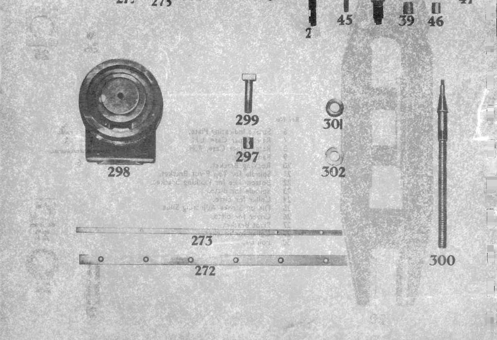
22 262 Pawl for ditto. 263 Spring for Pawl. 264 Knob. 265 Friction Pad. 266 Spring for ditto. 267 Catch for Ratchet Bracket. 268 Screw for ditto. 269 Gear Operating Spindle with Handle. 270 Ball for ditto. 271 Spring for ditto. 272 Strip on Body. 273 Ditto. 274 Bracket on Body. 275 Pad for ditto. 276 Lever for Bracket. 277 Pivot Screw. 278 Adjusting Screw. 279 Pin for Lever. 280 Screw Spindle. For 5M and 6M Machines only. 281 Bevel Gear on Shaft. For 5M and 6M Machines only 282 Bevel Gear on Shaft. For 5M and 6M Machines only 297 Distance Stop Collar. For 5M and 6M Machines only 298 Swivelling Head. For 5M and 6M Machines only 299 Bolt for Swivelling Head. For 5M and 6M Machines only 300 Screw Spindle. For 5M and 6M Machines only. 301 Graduated Collar. For 5M and 6M Machines only. 302 Lock Nut. For 5M and 6M Machines only. Parts Nos inclusive for machines fitted with auto down feed.


23
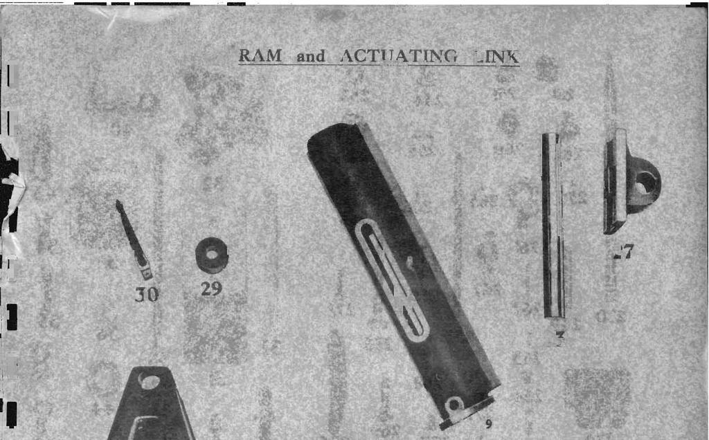
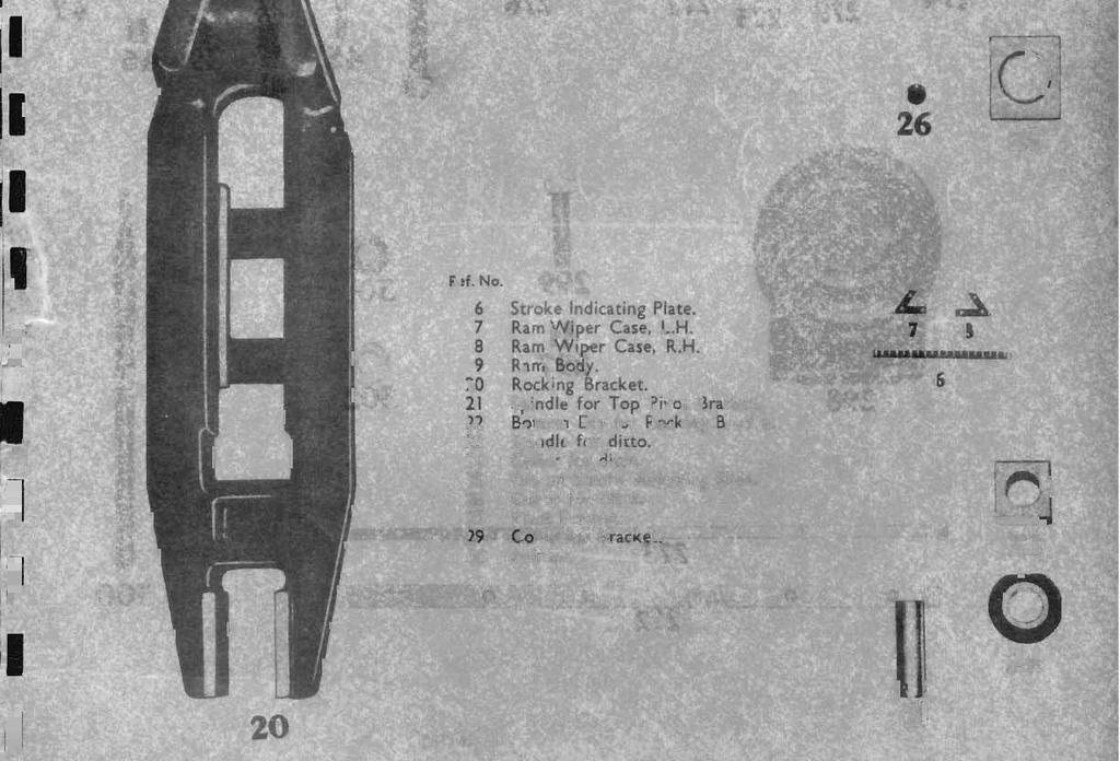
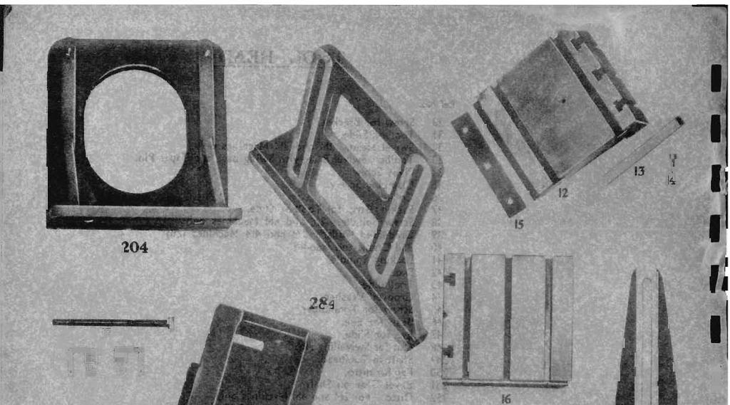
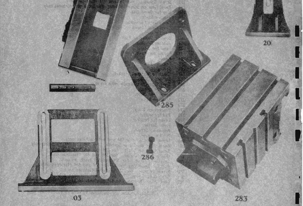
24 TABLE & CROSS SLIDE Ref. No. 10 Main Slide Body. 11 Packing Strip for Main Slide Body. 12 Cross Slide Body. 13 Top Adjusting Taper Strip. 14 Screw for Top Adjusting Taper Strip. 15 Bottom Strip. 16 False Table. 17 Bolts For False Table. 18 Wiper Case, R.H. 19 Wiper Case, L.H. 201 Table Support Bracket. For 2M, 4M and SM Machines only with fixed table. 202 Slide for Support Bracket with bolt. For 2M and 4M Machines only. 203 Table Support Bracket. For 6M Machine only with fixed or swiveltable. 204 Table Support Bracket. For 6M Machine only with fixed table. 283 Cross Slide Body complete with False Table. 284 Table support for 2M, 4M and 5M Machines with swivel table. 285 Table Support Bracket. For all models swivel table. 286 Tee-headed Bold for ditto. 287 Slide Strip for Table Support.
25
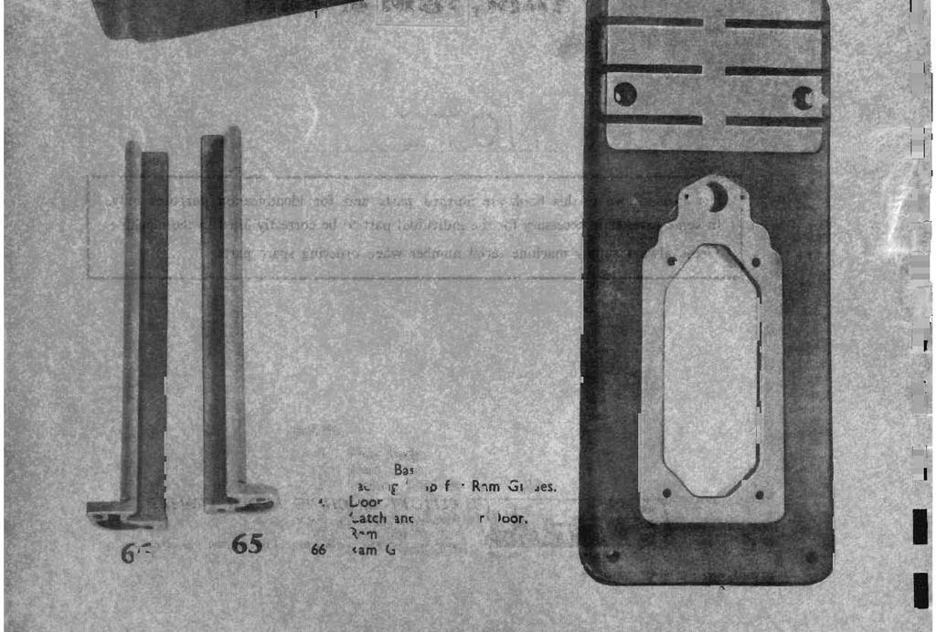
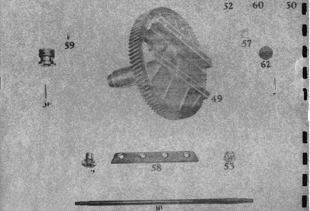
26 BULL WHEEL & SELF ACT Ref. No. 49 Bull Gear. 50 Stroke Adjusting on Spindle 51 Bevel Gear on Stroke Adjusting Spindle 52 Stroke Adjusting Screw. 53 Bevel Gear on Stroke Adjusting Screw. 54 Locking Nut for Adjusting Spindle. 55 Taper Pin for Bevel Gear on Adjusting Spindle. 56 Taper Pin for Stroke Adjusting Screw. 57 Collar for ditto. 58 Strip for Bull Gear. 59 Stop in Boll Gear, for Stroke Adjusting Slide. 60 Stroke Adjusting Slide. 61 Bracket in Bull Gear. 62 Oil Well Cover for Bull Gear Bracket. 67 Operating Shaft (Table Raising). 68 Graduated Collar. 69 Bevel Gear, for Shaft. 70 Taper Pin for ditto. 71 Internal Screw. 72 Nut for Screw. 73 Bevel Gear on Screw. 74 External Screw. 75 Nut for ditto. 76 Bracket for Telescopic Screw. 77 Collar for Internal Screw. 78 Thrust Bearing. 79 Cross Slide Nut.
27 80 Cross Traverse Screw. 81 Collar for ditto. 82 Rubber Washer. 11/64 hole. 83 Ditto. 48/64 hole. 84 Self Act Gear Case. 85 Flush Type Lubricator. ½ hole 86 Self Act Gear on Bull Gear. 87 Self Act Driven Gear. 88 Spindle for ditto. 89 Collar for ditto. 90 Pivot Sleeve. 91 Connecting Link. 92 Tee Bolt. 93 Hand Grip Nut. 94 Self Act Link. 95 Cover for Self Act Gear Case. 96 Self Act Bracket. 97 Pin for Self Act Link in Bracket. 98 Pawl for Self Act Bracket. 99 Spring for Pawl. 100 Knob. 101 Flush Type Lubricator. ¼ dia. 102 Sleeve for Self Act Bracket. 103 Self Act Ratchet on Traverse Screw. 104 Driving Collar. 105 Taper Pin for ditto. 106 Thimble and Driving Collar. 107 Shear Pin.

28 MOTOR DRIVE
29
30
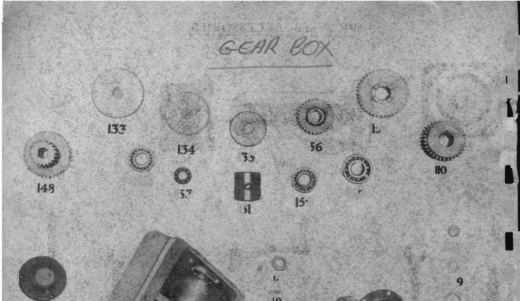
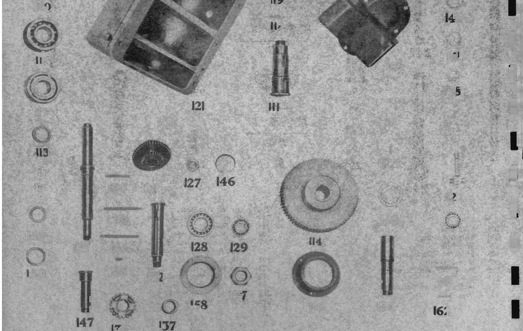
31 GEAR BOX Ref. No. 110 Bull Gear Pinion. 111 Intermediate Shaft. 112 Nut for Intermediate Gear. 113 Distance Piece. 114 Intermediate Gear. 115 Housing for Bearing. 116 Ball Bearing 1-5/8 bore. 117 Ball Bearing 1-3/4 bore. 118 Key for Bull Gear Pinion. 119 Key for Intermediate Gear. 120 Cover for Intermediate Shaft. 121 Gear Box Casing. 122 Oil Level Casing. 123 Dowel Pin. 124 Plug for Filling & Draining. 125 Input Shaft. 126 Sliding Gear 35, 45, & 26 Teeth. 127 Hexagon Nut. 128 Ball Bearing 1-1/4 bore. 129 Ball bearing 7/8 bore. 130 Key for Clutch. 131 Key for Sliding Gear. 132 Intermediate Shaft st Speed Gear 64t nd Speed Gear 55t rd Speed Gear 45t. 136 Constant Speed Mesh Gear 21t.
32 137 Distance Piece for Gears. 138 Dsitance Piece for Shaft. 139 Nut. 140 Distance Sleve for Bearing. 141 Distance Piece for 2 nd Speed gear. 142 Ball Bearing 1-1/8 dia Bore. 143 Ball Bearing 7/8 dia Bore. 144 Key for 1 st 2 nd and 3 rd Speed Gears. 145 Key for Constant Mesh Gear. 146 Seeger Circlip 1-7/8 Bore. 147 Back Gear Shaft. 148 Back Gear 39 and 20t. 149 Distance Piece for Back Gear Shaft. 150 Distance Piece for Bearings. 151 Distance Sleve for Bearings. 152 Ball Bearing 1-1/4 Bore. 153 Ball Bearing 7/8 Bore. 154 Final Grive Shaft. 155 Final Sliding Gear 40t. 156 Gear on Final Drive Shaft 29t. 157 Nut. 158 Housing for Bearing. 159 Ball Bearing 1-1/4 Bore by 11/16 Wide. 160 Ball Bearing 1-1/4 Bore by 7/8 Wide. 161 Key for Sliding Gear. 162 Key for Final Drive gear. 163 Case for Control Gear.
33
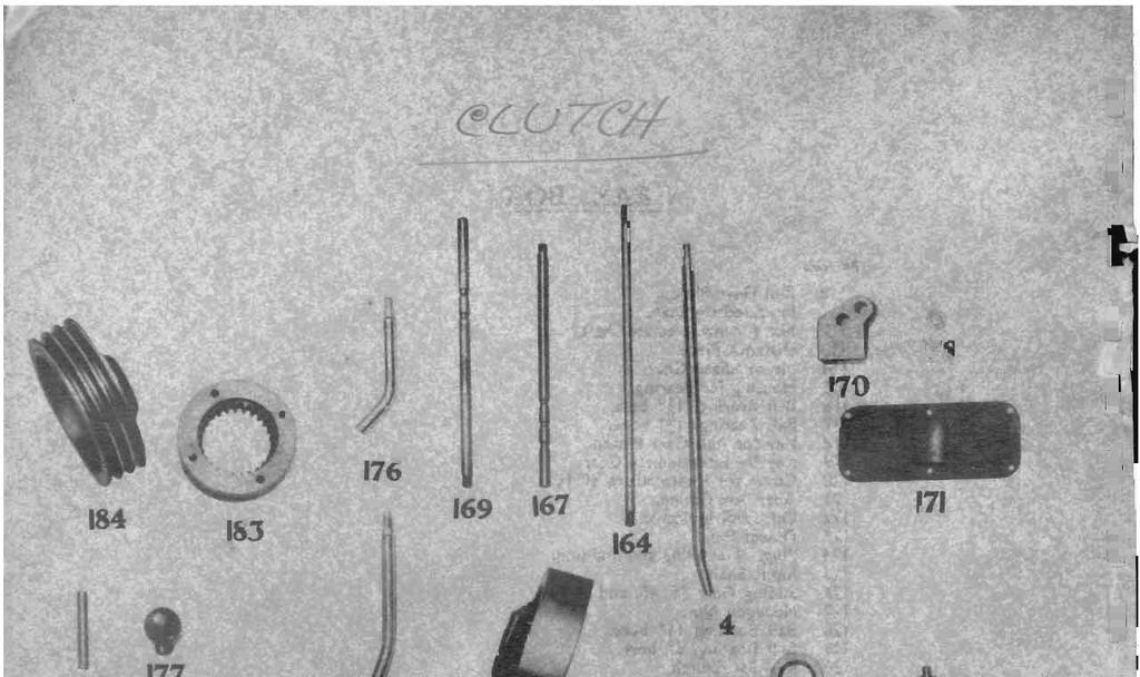
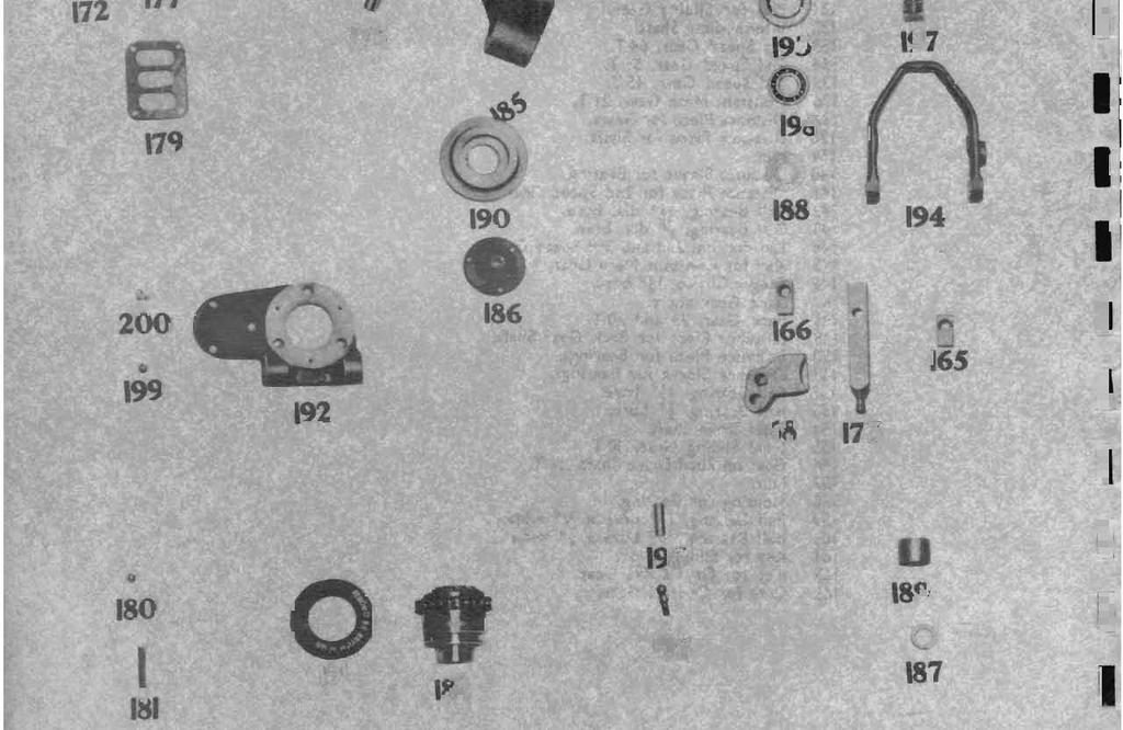
34 GEAR BOX Ref. No. 164 Clutch Rod. 165 End for Control Rod. 166 End for Clutch Rod. 167 Change Speed Rod. 168 Die for ditto. 169 Back Gear Rod. 170 Die for ditto. 171 Rear Cover. 172 Pivot Pin for Levers. 173 End for Levers. 174 Clutch Lever. 175 Change Speed Lever. 176 Back Gear Lever. 177 Knob for Levers. 178 Distance Piece for Levers. 179 Gate Plate. 180 Index Ball. 181 Spring for ditto. 182 Single Multi Disc Clutch. 183 Clutch Adaptor. 184 Driving Pulley for Vee Belts. 185 Driving Pulley for Vee Belts. 186 Cover for ditto. 187 Distance Piece for Pulley Bearings. 188 Grease Retaining Ring. 189 Distance Sleeve for Brake Plate.
35 190 Brake Plate. 191 Ferodo Disc. 192 Cover for Gear Box Clutch End. 193 Gitseal. 194 Clutch Actuating Fork. 195 Pivot Pin for ditto. 196 Ball End for Fork. 197 Die for Clutch Fork. 198 Ball Bearing, 7/8 bore. 199 Tecazerk Lubricator, 1/8 Gas. 200 Key for Brake Plate.
Hopkinsons Fig 9052 VALVE ACTUATOR
 Excellent Power & Industrial Solutions Standard Operating & Maintenance Instructions Hopkinsons Fig 9052 VALVE ACTUATOR CUT-AWAY OF FIG. 9052 GEAR BOX, WITH LIMIT SWITCH & VALVE POSITION INDICATOR HOP
Hopkinsons Fig 9051 VALVE ACTUATOR
 Excellent Power & Industrial Solutions Standard Operating & Maintenance Instructions Hopkinsons Fig 9051 VALVE ACTUATOR TERMINAL BOX TERMINAL BOX COVER SPINDLE COVER SEAL BEARING HOUSING MOTOR TAPERED
Hopkinsons Fig 9151 Issue pre 1980 VALVE ACTUATOR
 Excellent Power & Industrial Solutions Standard Operating & Maintenance Instructions Hopkinsons Fig 9151 Issue pre 1980 VALVE ACTUATOR CUT AWAY OF FIG 9151 VALVE ACTUATOR HOP 9151 / Issue Pre 1980/Jan
 AUTOGARD SERIES 820 TORQUE LIMITER Installation and Maintenance Manual DB0009 Issue 11 21 Feb 2017 British Autogard Ltd 2 Wilkinson Rd., Love Lane Industrial Estate, Cirencester, Glos., GL7 1YT UK Tel.
MAIN PRICE LIST. - B 487 Perforated Strip 2 1/2" B 488 Perforated Strip 3 1/2" B 482 Perforated Strip 4 1/2" 9 1.
 PERFORATED STRIPS LENGTH HOLES GBP 1 Perforated Strip 12 1/2" 25 1.63 1 a Perforated Strip 9 1/2" 19 1.51 1 b Perforated Strip 7 1/2" 15 1.39 2 Perforated Strip 5 1/2" 11 0.90 2 a Perforated Strip 4 1/2"
PARTS. For Machines Mfg. Since 8/09. Headstock 133A 127A 107A 105A 73A 55A 37A -69-
 For Machines Mfg. Since 8/09 Model SB1028-69- Headstock 1 2 3 4 5 6 7 8 9 10 11 12 13 14 15 17 18 19 20 21 22 23 24 25 26 27 28 29 30 31 32 33 34 35 36 37 38 39 40 41 42 43 44 45 46 47 48 49 50 51 52 53
Chain Box and Knife. Item # Description Part Number 180-D & GS
 Chain Box and Knife Item # Description Part Number 180-D & GS 1 Groove pin 2275-03160 2 Hex cap screw 2175-03061 3 Washer 2275-03060 4 Setscrew 2175-07163 5 Chain box 4975-00355 6 Berkel logo 3175-00152
SERIES I MILLING MACHINES
 INSTALLATION, OPERATION, MAINTENANCE, AND PARTS LIST SERIES I MILLING MACHINES TP5260 Revised: August 29, 2005 Manual No. M-450 Litho in U.S.A. Part No. M -0009500-0450 June, 2003 CHAPTER 4 - PARTS LISTINGS
SECTION 9: PARTS. Main -59- Model G0747/G0748 (Mfg. Since 8/12)
") SECTION 9: PARTS Main 8 2 4 6 7 9 10 1 13 23 14 16 15 18 19 17 131 126 125 127 128 129 132 133 119 62 38 39 40 37 32 33 43 41 42 49 46 47 50 51 65 69 44 74 48 61 31 52 60 75 76 77 71 80 53 54 82 104 103
SECTION 9: PARTS Main 8 2 4 6 7 9 10 1 13 23 14 16 15 18 19 17 131 126 125 127 128 129 132 133 119 62 38 39 40 37 32 33 43 41 42 49 46 47 50 51 65 69 44 74 48 61 31 52 60 75 76 77 71 80 53 54 82 104 103
PARTS. Headstock 133A 127A 107A 72 73A A 55A 37A -71-
 -71- Headstock 1 2 3 4 5 6 7 8 9 10 11 12 13 14 15 17 18 19 20 21 22 23 24 25 26 27 28 29 30 31 32 33 34 35 36 37 38 39 40 41 42 43 44 45 46 47 48 49 50 51 52 53 54 55 56 57 58 59 60 61 62 63 64 65 66
CARD RECORDER MECHANISMS
 ITR Engineering Data Sheet 201 September 1927 CARD RECORDER MECHANISMS Card time recorders are used for registering on a card the time that employees enter and leave the factory. The card and the recorder
ON-THE-VEHICLE BRAKE LATHE
 800 ON-THE-VEHICLE BRAKE LATHE Parts Identification READ these instructions before placing unit in service. KEEP these and other materials delivered with the unit in a binder near the machine for ease
Hopkinsons Fig 9050M & 9151M Issue 1982 ELECTRIC ACTUATOR Modulating Duty
 Excellent Engineering Solutions Standard Operating & Maintenance Instructions Hopkinsons Fig 9050M & 9151M Issue 1982 ELECTRIC ACTUATOR Modulating Duty SECTIONAL ARRANGEMENT OF FIG. 9050M & 9151M ACTUATOR
Main Components Early Style
 Pipe & Bolt Threading Machine Main Components Early Style * * 0 0 0 0 0 Service Notes: Ref. No.. Do not substitute bolt longer than / inches. Severe damage to Rear Bearing will result. Ref. No.. To assure
Eye-bolt for front chain adjustment, Pre-49 singles, twins, 1958-on CS singles
 Part No. AJS & MATCHLESS GEARBOX & CLUTCH - NEW PARTS Price (20% VAT) Price (excl VAT) Tool for adjusting clutch spring nuts (heavier duty than 017254 spanner) 5.00 4.17 017254 Spanner, single end, dynamo
Valtek Auxiliary Handwheels and Limit Stops
 Valtek Auxiliary s and Limit Stops Table of Contents Page 1 General information 2 Installation 2 Side-mounted handwheels, size 25 and 50 (linear actuators) 3 Side-mounted handwheels, size 100 and 200 (linear
INDEX. PAGE Adjustment mechanism for radial position of block on rotating
 INDEX Adjustment mechanism for radial position of block on rotating arm 520 Amplifying mechanism for precision measuring instruments--491 Angular movement, crank and link mechanisms for increasing 251,
REAR TRANSMISSION-REAR AXLE
 REAR TRANSMISSION-REAR AXLE The rear axle is of the semi-floating type with a spiral bevel drive pinion and crown wheel as shown in the section view, Fig. 168. 7 The drive is splined into the front transmission
FRICK TIMBER TIGER SAWMILLS SIZES: 0 0C
 FRICK TIMBER TIGER SAWMILLS SIZES: 0 0C SERVICE S LIST PAGE 2 TIMBER TIGER 0 AND 0C SAWMILLS HOW TO USE S LIST This Parts List provides identification of Frick Timber Tiger s 0 and 0C Standard Sawmills
MODEL SB1024F 9" X 42" MILLING MACHINE w/dro. Manual Insert
 MODEL SB1024F 9" X 42" MILLING MACHINE w/dro Manual Insert PHONE: (360) 734-1540 www.southbendlathe.com The Model SB1024F Milling Machine is the same machine as the Model SB1024 except for the following:
SECTION H STEERING. Section Description Page No. H.1 GENERAL DESCRIPTION 3 H.2 STEERING WHEEL 3 H.3 INNER COLUMN 5 H.
 SECTION H STEERING Section Description Page No. H.1 GENERAL DESCRIPTION 3 H.2 STEERING WHEEL 3 H.3 INNER COLUMN 5 H.4 OUTER COLUMN 5 H.5 STEERING UNIT LOCK STOPS 6 H.6 STEERING UNIT 6 H.7 STEERING ARMS
COUNTER SHAFT NUT LOCKING PLATE 1 $ HOIST DRUM CLUTCH EYE BOLTS 1 $ LEFT DRUM CLUTCH THREADED PIN 2 $ 138.
 1 2184 PULLEY FOR RADIATOR FAN 1 $ 326.25 2 2184 PULLEY FOR RADIATOR FAN 1 $ 326.25 3 3331 REAR DRUM BRAKE RETURN SPRING 5 $ 51.31 5 10285 LEFT REAR DRUM BRAKE AIR CAN REACH ROD ( LONG ROD ) 1 $ 85.12
Edition October 2014 Part No
 Edition 1.3 - October 2014 Part No. 8999076 1 Contents Ordering Your Parts... 3 Centre Section - S180025.70... 5 Wing Section - S180025.71/72...7 Centre Axle - S180025.110... 9 Wing Axle - S180025.111...10
Marine Engineering Exam Resource Review of Couplings
 1. What are rigid couplings used for? Used to join drive shafts together. True alignment and rigidity are required. Example Drive shafts and production lines, bridge cranes, solid shaft that needs to be
NOTE: Order parts by Catalog Number Only. DO NOT order by Reference Number.
 K-C/K-R Cage Machine Transportation Cart Assembly 0 NOTE: Order parts by Catalog Number Only. Ref. No. 0 Catalog No. 00 000 0 0 0 0 0 00 0 0 0 0 0 Description Cart Assembly Hex Nut /" () Lock Washer /"
Spearhead Multicut 460 MULTICUT th Edition - July 2015 Part No
 MULTICUT 460 14 th Edition - July 2015 Part No. 8999023 1 Spearhead Multicut 460 Parts Book 14 th Edition July 2015 Spearhead Machinery Ltd Green View Salford Priors Evesham Worcestershire WR11 8SW Tel:
ADJUSTMENT AND TESTING
 1 4.1 Initial adjustments SECTION IV ADJUSTMENT AND TESTING 4.1.1 Initial adjustment of Driving Rod (Ref: SEM Part II Para 19.35) After installation of the point machine as per standard layout: Insert
Spearhead STARCUT 500 STARCUT 500. Edition Jan 2013 Post Serial No. S Part No
 STARCUT 500 Edition 2.0 - Jan 2013 Post Serial No. S136498 Part No. 8999040 1 Contents Ordering Your Parts 3 Centre Section 4 Wing Section 6 Centre Axle 8 Wing Axle 10 Std Drawbar 12 Tie-Bar Assembly 14
MODEL A-I-SPECIFICATIONS
 ARTER Model A Rotary Surface Grinders are built in a light and heavy series. General Construction- The general design of both models is the same but the major units of the A-3 machines are of greater proportions.
MTMANUAL TRANSMISSION GENERAL 1. SPECIFICATIONS. 1) General Specifications. 2) Tightening Torque MANUAL TRANSMISSION
 General Specifications. 2) Tightening Torque MANUAL TRANSMISSION") 03-3 MT GENERAL 1. SPECIFICATIONS 1) General Specifications 2) Tightening Torque 03-4 OVERVIEW AND OPERATION PROCESS 1. OVERVIEW 4WD Features 1. All gears use the helical type and high strength materials.
03-3 MT GENERAL 1. SPECIFICATIONS 1) General Specifications 2) Tightening Torque 03-4 OVERVIEW AND OPERATION PROCESS 1. OVERVIEW 4WD Features 1. All gears use the helical type and high strength materials.
No. CLMP05 January 11, Parts Price List Clausing Lathes & Mills P.O. BOX 877 GOSHEN, IN PHONE (574) FAX (574)
 FAX (574)") No. CLMP05 January 11, 2005 P.O. BOX 877 GOSHEN, IN 46527-0877 PHONE (574) 533-0371 FAX (574) 533-0403 EMAIL info@clausingsc.com Website http://www.clausing-industrial.com Note: Please do not give credit
No. CLMP05 January 11, 2005 P.O. BOX 877 GOSHEN, IN 46527-0877 PHONE (574) 533-0371 FAX (574) 533-0403 EMAIL info@clausingsc.com Website http://www.clausing-industrial.com Note: Please do not give credit
6-speed manual gearbox 0A5
 Service Training Self-study programme 320 6-speed manual gearbox 0A5 Design and function S320_002 In addition to meeting increasing technical demands, modern cars also have to represent effective space
CS Stationary Engines
 CS Stationary Engines Listeroid or Indian Lister or Lister Clones or generally speaking Lister CS (cold start) referred to as stationary engines, are one of the most versatile long running stationary engines
1 HR-301/D Parts Manual. Table Of Contents
 Table Of Contents 301/D Parts Manual 3 Point Hitch...2 Pull-Type Hitch...4 Main Frame...6 Angle Adjuster - Serial Number 44982 & Prior...8 Rotor Assembly - Serial Number 44982 & Prior...10 Rotor Assembly
1822-I/1822-IC. Spindle Assembly. Pipe & Bolt Threading Machine. Ridge Tool Company/Elyria, Ohio, U.S.A. 2* 3 4 5* *
 -I/-IC Spindle Assembly * * * 0 * * * 0 * * 0* * * Rear Cover * Screw () * Washer () Top Cover w/clips (Includes,, ) * J Clip () Front Cover * Screw () Pivot Rod Support () Pivot Rod () 0 Shoulder Screw
SAFETY FIRST! HEALTH AND SAFETY AT WORK WARRANTY
 1. READ THE INSTRUCTION BOOK THOROUGHLY before attempting to operate or carry out any maintenance on the machine. If you do not understand any part of this manual, ask your dealer for assistance. 2. ALWAYS
1 RS-300/D 320/D 340/D 350H Parts Manual
 300/D 320/D 340/D 350H Parts Manual Table Of Contents Three Point Hitch / Hitch Frame Assembly... 3 Tongue Pull Hitch Assembly... 7 Main Gearbox... 11 Crank Handle & Gear... 13 Hydraulic Lift... 15 Rotor
PARTS LIST FOR MECCANO No. 10 vs No. 7 & "L" 10/37? P/N Description 7/25 10/49 10/49 10/55 10/86 L 1 Perforated Strip 25 holes a
 PARTS LIST FOR MECCANO No. 10 vs No. 7 & "L" 10/37? P/N Description 7/25 10/49 10/49 10/55 10/86 L 1 Perforated Strip 25 holes 50 24 24 24 24 38 1a Perforated Strip 19 holes 12 6 6 6 6 16 1b Perforated
SINGLE WIDE MASTER CATALOG GOSS COMMUNITY UNIT GOSS COMMUNITY FOLDER
 SINGLE WIDE MASTER CATALOG GOSS COMMUNITY UNIT GOSS (Click on the name to be taken to that section) Stocking Manufacturer of Quality Replacement Parts (815) 965-0884 Fax (815)965-1049 Welcome to the Quality
SWINGTRIM Swingover Cutterbar Trimmer
 Publication 117(PM) December 2007 Part No. 1090850 Revision: 2 SWINGTRIM Swingover Cutterbar Trimmer Parts Manual For best performance USE ONLY McCONNEL SERVICE PARTS To be assured of the latest design
SALES DIVISION NETWORK TECHNICAL INFORMATION WORKSHOP MANUAL MOTOR ENGINE
 SALES DIVISION NETWORK TECHNICAL INFORMATION WORKSHOP MANUAL MOTOR ENGINE CONTENTS CHARACTERISTICS... 5 Engine markings... 5 TIGHTENING TORQUES... 5 SPECIAL TOOLS... 6 IDENTIFICATION... 7 Differences between
Service Manual. #19 Gearmatic Winch
 Allis Chalmers Service Manual #19 Gearmatic Winch Service Manual THIS IS A MANUAL PRODUCED BY JENSALES INC. WITHOUT THE AUTHORIZATION OF ALLIS CHALMERS OR IT S SUCCESSORS. ALLIS CHALMERS AND IT S SUCCESSORS
SECTION 7B3 - MANUAL TRANSMISSION - GEN III V8 ENGINE
 SECTION 7B3 - MANUAL TRANSMISSION - GEN III V8 ENGINE CAUTION: This vehicle will be equipped with a Supplemental Restraint System (SRS). An SRS will consist of either seat belt pre-tensioners and a driver's
5/29/2014 3MSHY 2000 / CYLINDER CRANKCASE Yamaha Motor Corporation, U.S.A. All rights reserved.
 Page 1 of 22 3MSHY 2000 / CYLINDER CRANKCASE Page 2 of 22 Part List 3MSHY 2000 / CYLINDER CRANKCASE REF - NO PART NUMBER PART NAME QUANTITY REMARKS 1 6L5-W0090-01-1S CRANK CYLINDER ASSY 1 2 6L5-15100-00-1S
Crestline Altra Series TM Dampener. Installation Instructions. Heidelberg GTO. X /98 Rev-A
 Crestline Altra Series TM Dampener Installation Instructions Heidelberg GTO X88-63 7/98 Rev-A GENERAL INFORMATION ATTENTION CRESTLINE ALTRA SERIES TM DAMPENER OWNER! Accel Graphic Systems provides parts
5/29/2014 3MSHU 1996 / CYLINDER CRANKCASE Yamaha Motor Corporation, U.S.A. All rights reserved.
 Page 1 of 22 3MSHU 1996 / CYLINDER CRANKCASE Page 2 of 22 Part List 3MSHU 1996 / CYLINDER CRANKCASE REF - NO PART NUMBER PART NAME QUANTITY REMARKS 1 6L5-W0090-01-4D CRANK CYLINDER ASSEMBLY 1 2 6L5-15100-00-94
REF. NO. DESCRIPTION TOP COWLING 2 MOLDING, AIR DUCT 3 RIVET 4 SEAL 5 HOLDER, CLAMP BAND 6 BOLT, WITH WASHER 7 HOOK
 SUZHOU ALLPASS MACHINERY CO.,LTD Add:No.85,Jishui Road,Jinfeng Industrial Park,Mudu Town,Suzhou 215102,Jiangsu,P.R.China T15 SPARE PARTS EXPLODED DRAWING FIG. 1 1 TOP COWLING TOP COWLING 2 MOLDING, AIR
Group 1: Gearbox housing
 1 Five-Speed gearbox crown wheel 11 Nylon socket for speed- 21 Screw 31 Tube 2 Plug 12 Cup 22 Screw 32 Deflector 3 Gearbox and clutch housing 13 Pinion f. speedometer 23 Screw 33 s 4 Front cover 14 Stop
365L (2001) Page 1 of 36 54" Deck Assembly
 Page 1 of 36 54 Deck Assembly") 365L (2001) Page 1 of 36 54" Deck Assembly 365L (2001) Page 2 of 36 54" Deck Assembly 1 720-0241 1 S Wing Nut Knob 2 703-2817 1 Belt Cover LH 3 703-2816 1 Belt Cover RH 4 747-3306 1 Idler Spring Mounting
365L (2001) Page 1 of 36 54" Deck Assembly 365L (2001) Page 2 of 36 54" Deck Assembly 1 720-0241 1 S Wing Nut Knob 2 703-2817 1 Belt Cover LH 3 703-2816 1 Belt Cover RH 4 747-3306 1 Idler Spring Mounting
BUSH HOG LAND MAINTENANCE REPAIR PARTS MANUAL MODEL: 3414 SECTION: 67
 BUSH HOG LAND MAINTENANCE REPAIR S MANUAL MODEL: SECTION: 0 Griffin Ave. Selma, AL 0 () - () -00 Parts Ordering -00-0- Fax -00-- www.bushhog.com BUSH HOG/ LAND MAINTENANCE REPAIR S MANUAL July, 0 ROTARY
9/8/ MSHZ 2001 / TOP COWLING Yamaha Motor Corporation, U.S.A. All rights reserved.
 9.9MSHZ 00 Page of 47 9/8/04 9.9MSHZ 00 / TOP COWLING 04 Yamaha Motor Corporation, U.S.A. All rights reserved. 9.9MSHZ 00 Page of 47 9/8/04 Part List 9.9MSHZ 00 / TOP COWLING REF - NO PART NUMBER PART
DB4604 GMR-SD and GMR40-SD Disc Brake Caliper - Spring Applied, Air Released
 DB464 GMR-SD and GMR4-SD Disc Brake Caliper - Spring Applied, Air Released Nominal dimensions given. For specific dimensions please contact Twiflex Limited. For GMR Mk 2 caliper details see DB 364 Air
PWC - 33
 PWC - 33 WY33N13BS SPARE PARTS LIST Mower Assembly Caster Kit Ref.# Part# Description Ref.# Part# Description 1 3301010 Linchpin 11 B6182-12 Lock nut M12 2 B97.1-20 Washer 20 12 3301040 Caster Wheel Arm
Compact 6-Speed and Reverse Gearbox
 Compact 6-Speed and Reverse Gearbox By Alan Wenbourne Downloaded from the South East London Meccano Club Website www.selmec.org.uk The Gearbox During the construction of my demonstration Direct Shift Gearbox
Parts List. Models 7100, 7150 Dual Chop. Serial No: from Serial No: from Serial No: Owners Club Registration
 Models 7100, 7150 Dual Chop Parts List 7100 - from Serial No: 30283 - from Serial No: 10075 Serial No: Owners Club Registration Issue 08/16 7100/7150 1. READ THE INSTRUCTION BOOK THOROUGHLY before attempting
INSTRUCTION MANUAL. Series PROCUNIER SAFETY CHUCK CO. (Serial Nos. B4870 and higher. (Serial Nos. B9230 and higher
 PROCUNIER SAFETY CHUCK CO. 304 Winston Creek Parkway Lakeland, Florida 33810-2866 Telephone 863-688-0071 FAX: 863-682-6233 Series 29000 (Serial Nos. B4870 and higher (Serial Nos. B9230 and higher INSTRUCTION
Mulching and Finishing Mowers MP and FP
 Mulching and Finishing Mowers MP and FP Parts Manual Locke Turf 0 Highway E, Opp, Alabama, () -00 Transport Wheel, Tire & Spindle MP and FP ALPHABETICAL INDEX CONTENTS PAGE 00 Hydraulic Cylinder (Rear)
I:. #. AUTOMATIC PICK-UP HITCH MAJOR POWER MAJOR 1 SUPPLEMENT SECTION 10 COMPONENT PARTS. Fig. 2 Hitch Locked in Raised Position
 POWER MAJOR 1 SUPPLEMENT SECTION 10 AUTOMATIC PICK-UP HITCH I:. #. Fig. 1 Hitch in Lowered Position A hydraulically-operated pick-up hitch installation is available as optional equipment on current production
HANDLEBAR AND CONSOLE ASSEMBLY
 Section 6 Parts List HANDLEBAR AND CONSOLE ASSEMBLY 4 33 47 4 49 7 3 78 4 97 46 44 37 38 37 48 39 35 36 34 7 3 4 5 45 4 3 4 0 33 9 96 80 6 300 84 9 5 30 4 9 30 4 3 43 97 0 43 3 68 9 9 Models 753B, F753B
S 1525-G Industrial ADJUSTMENT MANUAL
 Industrial 55 55-S ADJUSTMENT MANUAL 55-G 56 This Manual is valid for machines from the following serial numbers onwards: # 7 68 96--8 597/00 Justieranleitung engl. 09. The reprinting, copying or translation
SECTION 9: PARTS Head Breakdown
 G3102/G3103 Vertical Mill -45-1 1-1 2 2-1 3 3-1 4 5 6 7 8 9 9-1 10 10-1 11 12 13 14 15 16 17 18 19 20 20-1 21 22 22-1 23 24 25 26 27 28 29 30 31 32 33 34 35 36 37 38 39 40 42 43 44 45 46 47 48 49 50 51
The 6-Speed Manual Gearbox 08D
 Service. Self-Study Programme 299 The 6-Speed Manual Gearbox 08D Design and Function The Touareg is an exclusive cross country vehicle with the driving properties and driving comfort of a sporty luxury
CLUTCH CONTENTS SERVICE DIAGNOSIS. (a) Worn or damaged disc assembly. (b) Grease or oil on disc facings. (c) Improperly adjusted cover assembly.
 Worn or damaged disc assembly. (b) Grease or oil on disc facings. (c) Improperly adjusted cover assembly.") CLUTCH CONTENTS -GROUP 6 Page CLUTCH HOUSING ALIGNMENT... 6 CLUTCH PEDAL FREE PLAY 1 CLUTCH RELEASE BEARING 5 CLUTCH RELEASE FORK... 5 CLUTCH SERVICING 2 PILOT BUSHING CRANKSHAFT TO TRANSMISSION DRIVE
CLUTCH CONTENTS -GROUP 6 Page CLUTCH HOUSING ALIGNMENT... 6 CLUTCH PEDAL FREE PLAY 1 CLUTCH RELEASE BEARING 5 CLUTCH RELEASE FORK... 5 CLUTCH SERVICING 2 PILOT BUSHING CRANKSHAFT TO TRANSMISSION DRIVE
BUSH HOG LAND MAINTENANCE REPAIR PARTS MANUAL MODEL: 280 SERIES SECTION: 59
 BUSH HOG LAND MAINTENANCE REPAIR S MANUAL MODEL: 0 SERIES SECTION: P.O. Box 0 Selma, AL 0-0 () - () -00 Parts Ordering -00-0- Fax -00-- www.bushhog.com BUSH HOG/ LAND MAINTENANCE REPAIR S MANUAL JUNE,
2720/12720 PARTS MANUAL 72A SECTION FLEX WING ROTARY MOWER
 0/0 This Manual applies to models 0 and 0 that use a blade pan which measures. blade hole center to blade hole center. Also blades measure 8. from hole center to blade tip. See Section if these dimensions
Parts Manual 125 Series MA
 Parts Manual 125 Series MA - 1 - HEADSTOCK ASSEMBLY - 2 - HEADSTOCK ASSEMBLY ITEM PART N DESCRIPTION QTY 1 1156300 Handle 2 2 900115 Self Locking Nut 3/8 UNF 2 3 1320500 Verticality Screw 2 4 900027 Bolt
Model KD 710 KD 712 KD 714 Spare Parts List
 Model KD 710 KD 712 KD 714 Spare Parts List Part No. KD1570063 From Serial No. CONTENTS Page No.. Contents... 2 Ordering Replacement parts... 3 Axle & Wheel... 4 Auger & Transmission... 6 2 Speed Gearbox...
1989 Jeep Cherokee. STEERING COLUMN' '1989 STEERING Jeep Steering Columns STEERING COLUMN STEERING Jeep Steering Columns
 STEERING COLUMN 1989 STEERING Jeep Steering Columns DESCRIPTION All models use collapsible steering columns. All columns have integral ignition switch and locking device. Optional tilt wheel is available
Crestline Dampening System. Installation Instructions. A.B. Dick 350, 360, 375 Single & Dual Lever Machines. X /01 Rev-A
 Crestline Dampening System Installation Instructions A.B. Dick 350, 360, 375 Single & Dual Lever Machines X88-20 01/01 Rev-A GENERAL INFORMATION ATTENTION CRESTLINE DAMPENER OWNER! Accel Graphic Systems
Spearhead Trident Trident 6000 Flail Mower
 Trident 6000 Flail Mower 8999094 Edition 1.0 May 2015 1 Contents Ordering Your Part s 3 S180015.130 Main Frame Assy - Mounted 4 S180015.131 Rear Linkage Assy 6 S180015.132 Trident 6000 LH Wing Arm Assy
Repair Manual VW 02J gearbox. INA GearBOX
 Repair Manual VW 02J gearbox INA GearBOX Special tools Pipe section, 50 mm: Press fitting of synchronizer body for third/fourth gear. Assembly of support bearing for input and output shaft. Part number:
OPERATING INSTRUCTIONS
 OPERATING INSTRUCTIONS When this Jack leaves the factory, the air release plug is closed to prevent the oil being spilled when the Jack is in transit. To simplify the air-venting of the oil chamber, a
Online version - not for reprint
 4. CLUTCH, CHAIN DRIVE, CHAIN BRAKE, CHAIN TENSIONER 4. Clutch Drum/Chain Sprocket 43RA007 VA 70RA005 VA - Remove the chain sprocket cover. Disengage the chain brake by pulling the hand guard toward the
Printed from CyberCat-STIGA Section: GARDEN ELECTRICAL SYSTEM
 Section: GARDEN ELECTRICAL SYSTEM Section: GARDEN ELECTRICAL SYSTEM 2312 2333 1 1 1134-3625-01 Harness 2 1 1134-3623-02.Interlock module 4 2 9849-8013-16 Screw 5 2 1134-3132-01 Cable holder 6 2 1134-3204-01
Repair Manual and Spare Parts List
 Pneumatic Drive Unit Type Techn. Doc. No. 352 and Accessories for Pipe Cutting Machine Darstellung kann vom Original abweichen Repair Manual and 580027000_Inst_en_Version_02 Repair General In general,
Special 45-rpm Changers
 12 Special 45-rpm Changers and Spindles Introduction. Record changers that play only 45-rpm records use much the same dropping, set-down, and trip mechanisms as other changers. They do have several unique
BUSH HOG LAND MAINTENANCE REPAIR PARTS MANUAL MODEL: 280 SERIES SECTION: 59
 BUSH HOG LAND MAINTENANCE REPAIR S MANUAL MODEL: 0 SERIES SECTION: 0 Griffin Ave. Selma, AL 0 () () 00 Parts Ordering 00 0 Fax 00 www.bushhog.com BUSH HOG/ LAND MAINTENANCE REPAIR S MANUAL October, 0 0
TSM54/52 MANUAL TRANSMISSION
 3B-1 SECTION 00 3B TSM54/52 MANUAL TRANSMISSION Table of Contents GENERAL INFORMATION... 3B-3 Overview... 3B-3 Specifications... 3B-4 System components... 3B-5 Shifting mechanism... 3B-17 Diagnostic information
9/7/2014 F9.9MSHV 1997 / CYLINDER CRANKCASE Yamaha Motor Corporation, U.S.A. All rights reserved.
 F9.9MSHV 997 Page of 45 9/7/04 F9.9MSHV 997 / CYLINDER CRANKCASE 04 Yamaha Motor Corporation, U.S.A. All rights reserved. F9.9MSHV 997 Page of 45 9/7/04 Part List F9.9MSHV 997 / CYLINDER CRANKCASE REF
136R616G190 Lawn Tractor FST-16 (1996) Page 1 of 27 42" Mowing Deck
 Page 1 of 27 42 Mowing Deck") 136R616G190 Lawn Tractor FST-16 (1996) Page 1 of 27 42" Mowing Deck 136R616G190 Lawn Tractor FST-16 (1996) Page 2 of 27 42" Mowing Deck 3 97600A 1 S 42" Deck Ass'y. Code: N notates a new part (not previously
136R616G190 Lawn Tractor FST-16 (1996) Page 1 of 27 42" Mowing Deck 136R616G190 Lawn Tractor FST-16 (1996) Page 2 of 27 42" Mowing Deck 3 97600A 1 S 42" Deck Ass'y. Code: N notates a new part (not previously
H-10 Field Vane Shear Apparatus SL842. Impact Test Equipment Ltd & User Guide.
 H-10 Field Vane Shear Apparatus SL842 Impact Test Equipment Ltd www.impact-test.co.uk & www.impact-test.com User Guide User Guide Impact Test Equipment Ltd. Building 21 Stevenston Ind. Est. Stevenston
Part list for Kawasaki H2, 1972
 Part list for Kawasaki H2, 972 . Cylinder head, cylinder. . Cylinder head, cylinder. 9205-049 NUT 0 m/m 2 2 40B400 WASHER-plain 4 m/m 2 3 46E400 WASHER-spring 4 m/m 2 4 92070-036 SPARK PLUG NGK B9 HS 3
Westingh'ouse Steam Turbines-I. B (Rev. 3) GOVERNOR, GOVERNING VALVE
 GOVERNOR, GOVERNING VALVE") Supersedes l. B. 697 (Rev. 2) Westingh'ouse Steam Turbines-I. B. 697 (Rev. 3) GOVERNOR, GOVERNING VALVE AND OIL PUMP This governor mechanism comprises a vertical shaft centrifugal weight governor a gear
Supersedes l. B. 697 (Rev. 2) Westingh'ouse Steam Turbines-I. B. 697 (Rev. 3) GOVERNOR, GOVERNING VALVE AND OIL PUMP This governor mechanism comprises a vertical shaft centrifugal weight governor a gear
NOTE: Parts are no longer available for this tool. The manual will continue on the next page.
 NOTE: Parts are no longer available for this tool. The manual will continue on the next page. Form A433C Date 1-95 INSTRUCTIONS & PARTS LIST FOR SIOUX VALVE FACE GRINDING MACHINES NO. 956, 957, & 958 (SERIAL
INDEX. 414 Agitator reversing mechanism which varies point of reversal. 250 Alternate and intermittent drive for two shafts
 INDEX Agitating device for pin hopper.----------------------------------------- 414 Agitator reversing mechanism which varies point of reversal. 250 Alternate and intermittent drive for two shafts.-----.----------.--..--
Craftsman Snow Thrower Model PARTS LIST
 Craftsman Snow Thrower Model 24.88955 11 13 3 26 24 9 1 18 54 6 25 15 20 23 16 5 14 1 55 9 4 4 28 8 30 2 5 56 35 36 46 3 39 50 53 43 38 48 52 42 51 41 40 49 4 44 31 45 31 21 29 34 9 19 10 32 22 26 Craftsman
S MULTICUT 430. Edition 1.3 June 2016 Part No
 S147565 MULTICUT 430 Edition 1.3 June 2016 Part No. 8999080 Contents Ordering your Parts...2 S180043.21 Centre Deck...3 S180043.22 LH Wing Deck.4 S180043.23 RH Wing Deck.5 S180043.11 Std Wheel Arm 6 S180043.25
TOLL FREE
 Title: GOSS METRO-LINER UNIT Table of Contents 1-888-434-0888 AIR SYSTEM Main Air Line & Unit Air Line 3 Pneumatic Switches & Indicators 4 Pneumatic Safety System 5 10 & 13 Side Legs - Operator Side 6
Norden. A Lancashire Mill Engine. Scale: 1:12
 Scale: 1:12 Neil M. Wyatt February 2009 Fig. 1: General Arrangement General Arrangement Sheet: 1 An Old Steam Engine DEAR SIR, In the ruins of an old mill at, near Rochdale, there is an old steam engine
Service Tools. Service and Repair Manual Model 900/950/990 ITEM PART NO. DESCRIPTION ITEM PART NO. DESCRIPTION ITEM PART NO.
 12 1 3 2 4 5 8 10 6 7 9 11 14 24 12 13 17 22 29 18 23 25 19 26 15 20 27 21 16 22 33 37 38 32 31 36 30 34 35 40 41 42 43 ITEM PART NO. DESCRIPTION 1 9170 0231 30 LONG ALLEN KEY 2 9170 0737 20 3/32 PIN PUNCH
Repair Manual and Spare Parts List
 Hydraulic Drive Unit Type Techn. Doc. No. 362 and Accessories for Pipe Cutting Machine Darstellung kann vom Original abweichen Repair Manual and 580067000_Inst_en_Version_03 Repair General In general,
SERVICE SHEET No. 515
 SERVICE SHEET No. 515 MODEL D7 DISMANTLING AND REASSEMBLY OF HUBS AND BRAKES Both wheels are fitted with ball journal bearings which do not require adjustment. The bearings are packed with grease during
Supplement to Spare Parts Catalogue. Model : FT Dual Transmission - F
 Supplement to Spare Parts Catalogue Model : FT - 60 Dual Transmission - F10001760 CONTENTS Tab. No. Sheet No. DESCRIPTION Page No. 1 101764-8 HEAD LIGHT, REAR LIGHT AND PLOUGH 1 LAMP 2 101766A-7 SHEET
SERIES GARDEN TRACTORS 1992 PARTS CATALOGUE CONTENTS
 2000 SERIES GARDEN TRACTORS 1992 PARTS CATALOGUE CONTENTS PAGE No. 2000 SERIES GARDEN TRACTOR - CHASSIS, BODY PANELS, WHEELS, SEAT ETC 2 4 2000 SERIES PTO DRIVE, FRONT AXLE, ELECTRICS, MOUNTING FRAME AND
LAND MAINTENANCE REPAIR PARTS MANUAL BUSH HOG MODEL: 307 SECTION: 16
 BUSH HOG LAND MAINTENANCE REPAIR S MANUAL MODEL: 0 SECTION: P.O. Box 0 Selma, AL 0-0 () - () -00 Parts Ordering -00-0- Fax -00-- www.bushhog.com BUSH HOG / LAND MAINTENANCE REPAIR S MANUAL SEPTEMBER, 0
GMR-S and GMR40-S Disc Brake Caliper - Spring Applied, Air Released
 (GMR) 9 (GMR) ø GMR-S and GMR-S Disc Brake Caliper - Spring Applied, Air Released DB Nominal dimensions given. For specific dimensions please contact Twiflex Limited. For GMR Mk caliper details see DB
BUSH HOG LAND MAINTENANCE REPAIR PARTS MANUAL MODEL: 405 / 406 SECTION: 17
 BUSH HOG LAND MAINTENANCE REPAIR S MANUAL MODEL: 0 / 0 SECTION: 0 Griffin Ave. Selma, AL 0 () - () -00 Parts Ordering -00-0- Fax -00-- www.bushhog.com BUSH HOG/ LAND MAINTENANCE REPAIR S MANUAL SEPTEMBER,
13AU609H063 (1999) Page 1 of 25 Axle & Wheels Front And Steering Assembly
 Page 1 of 25 Axle & Wheels Front And Steering Assembly") 13AU609H063 (1999) Page 1 of 25 Axle & Wheels Front And Steering Assembly 13AU609H063 (1999) Page 2 of 25 Axle & Wheels Front And Steering Assembly 1 683-0304 1 S Frame 2 710-0604A 1 /P Self-tapping Screw,
13AU609H063 (1999) Page 1 of 25 Axle & Wheels Front And Steering Assembly 13AU609H063 (1999) Page 2 of 25 Axle & Wheels Front And Steering Assembly 1 683-0304 1 S Frame 2 710-0604A 1 /P Self-tapping Screw,
37A- S/N 350,000 Up. Turbine Drive Water-Reels. Engine Drive Slurry-Reels T37A E37A. Parts Manual. Serial No. 350, ,999
 37A- S/N 350,000 Up Turbine Drive Water-Reels Engine Drive Slurry-Reels T37A E37A Parts Manual Serial No. 350,000-359,999 700 S. Schrader Ave. Havana, Illinois 62644 Phone: 309-543-4425 Fax: 309-543-4945
There are few directions to maintain and operate the valves which are explained below for each valve.
 There are few directions to maintain and operate the valves which are explained below for each valve. MAINTENANCE INSTRUCTION FOR SLUICE GATE AS PER IS:3042/IS:13349 1. Frame (Serial No.- 2 of Drawing)