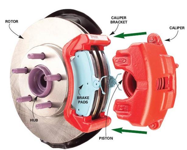
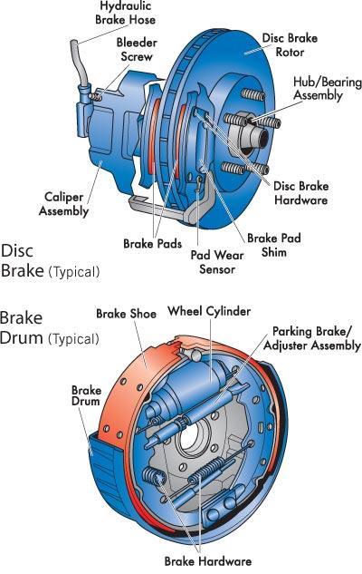
ATASA 5 th. ABS & Traction Control Systems. Please Read The Summary
|
|
|
- Branden Dean
- 5 years ago
- Views:
Transcription
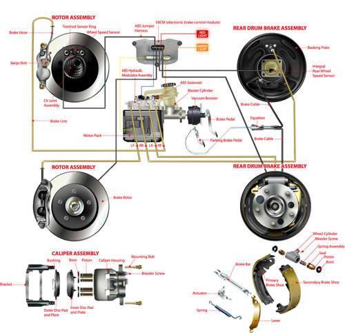
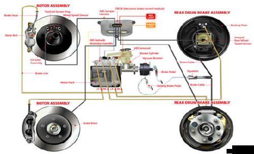
1 ATASA 5 TH Study Guide Chapter 51 Pages: Antilock Brake Systems 59 Points Please Read The Summary

2 Before We Begin Keeping in mind the Career Cluster of Transportation, Distribution & Logistics Ask yourself: What careers might be present in this slide series? What careers might interest me? How do these careers relate to my other high school classes? What career cluster is my 4 year plan preparing me for?
3
4
5
6
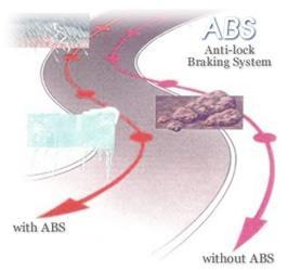
7 1. ABS systems use an / pumping of the brakes to control straight line stopping under panic conditions. (ABS is very fast, up top 15 x/second, & very precise) Electronic/Hydraulic Mechanical/Chemical Electrical/Solar
8

9

10 2. Pressure is the term used to describe the quick apply & release of brake system pressure by the antilock brake system. (preventing lock up leads to better maneuverability & stability) Modulation Cavitation Electrification

11 3. is the difference between the actual speed of the vehicle and the speed of the tire s tread as it rotates on the pavement. With ABS, the target slip rate is 10% to 30% Slip Rate Clip Rate Ship Shape


12 4. It s the traction of the that actually stops the vehicle. ABS adjusts slip rate at each tire. Wheels Tires Pads & Shoes

13 5. If the driver pumps the brakes while stopping, this prevents ABS from activating! True or False

14 6. When ABS is activated, a small followed by rapid pedal will continue until the vehicle either comes to a stop or the ABS turns off. Grind, Vibration Bump, Pulsations Thump, Reverberation

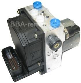
15 7. There are both and / components in each ABS system. These are also used for traction control system operation. Hydraulic, Electrical/Electronic Pneumatic, Electrical/Electronic Polytechnic, Electrical/Electronic

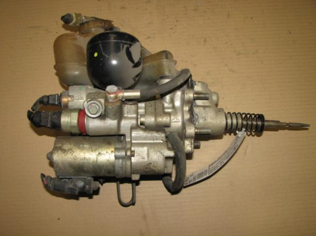
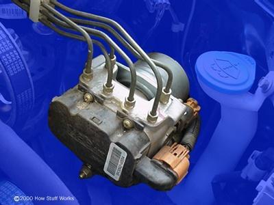
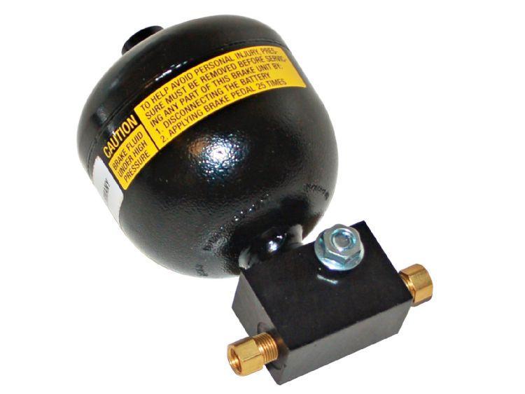
16 8. The nitrogen charged is used to store the hydraulic fluid used to maintain high ABS pressure. It may also be used to store residual pressure for power assisted braking. Accumulator Defibrillator Modulator
.")
17 9. The control valve assembly may be an part of the master cylinder assembly or may be mounted externally away from the master cylinder (non integral). Extrinsic Integral Add on
18


19 10. The pump, an assembly of an electric motor & pump, provides pressurized fluid. Booster Rooster Master Cylinder

20 11. The booster/ master cylinder assembly, sometimes referred to as the hydraulic unit, contains the valves and pistons needed to modulate hydraulic pressure. Control Retro Master

21 12. Fluid are different than pressure accumulators. They are used to temporarily store brake fluid removed from the wheel brake units during an ABS cycle. Accumulators Retractors Integrators
22

23 13.The valve is a two position valve that is only open during the ABS mode. Main Solenoid Actuator


24 14. The unit is made up of solenoid valves used to either, increase, decrease, or maintain hydraulic pressure to the individual wheel units. The valve block may also contain solenoids. Accumulator Defibrillator Modulator
25 15. There are two solenoid valves known as wheel valves used to control each channel. Circuit Circus Sirius

26 16. The ABS control module relies on input from the speed sensors and feedback from the hydraulic unit to determine if ABS is operating properly or which mode of ABS is required. Crankshaft Transmission Wheel
27 ABS is part of the High Speed CAN. There are also Medium Speed and Low Speed Controller Area Networks on the vehicle.


28 17. The brake position sensor (BPP) determines pedal travel & signals the ECU that an ABS event is taking place. This along with wheel speed sensor input causes a system reaction. Bracket Pedal Light


29 18. ABS systems have their own for faults which are accessed through the OBDII DLC. DTCs PIDs KIDs


 is stored.")
30 19. The colored warning lamp illuminates during vehicle startup & ABS system self check as well as when a DTC (Diagnostic Trouble Code) is stored. Red Amber Blue

31 20. A acceleration sensor is used on vehicles with ABS and stability control. Radial Lateral Circular


32 21. A switch automatically controls the ground side of the pump relay energizing and de energizing the pump to maintain proper accumulator pressure. Pressure Solenoid Actuator


33 22. The ABS system has that complete the high current circuits for the pump motor. Relays Solenoids Breakers


34 23. The ring (reluctor or toner ring) of the wheel speed sensing device can be located on an axle shaft, differential gear, or a wheel hub. Gear Toothed Fanged


35 24. The wheel speed sensor (coil & permanent magnet) & toner ring generate an voltage signal. AC DC MC

36 25. The electronic circuit & wiring of ABS is tied into the vehicle s CAN. This is a means of transferring information between computers on a serial data bus. (Multiplexing) Network Channel Circuit

37 26. The ABS control unit operates / valves in the hydraulic control unit that block off or isolate the master cylinder from certain brakes. These are corner specific valves. Isolation/Dump Insulation/Bump Isolation/Pump

38 27. Manufacturers have unique ways of accomplishing ABS operation. systems with conventional power assisted master cylinders & separate ABS hydraulic control units are typical. Integral Non integral

39 28. is the name given to a hydraulic circuit to the brakes. (ABS can be 1,2,3, or 4 channel) Channel Canal Actuator
 Rear Wheel Anti Lock Rear Antilock Brake System Rear Right")
40 29. Light trucks and some SUV s use 1 channel ABS on just the brakes. (RWAL or RABS) Rear Wheel Anti Lock Rear Antilock Brake System Rear Right Left

41 30. A diagonally split system may us a channel system that modulates opposite corners

42 31. A channel system will individually control each front brake but employ an RWAL system
43 32. The most effective and most commonly available ABS is the channel system with a sensor for each wheel. Normal braking is done by a conventional vacuum power assist system
44 33. Based on input from wheel speed sensors, the ABS control module calculates the rate of the wheels and then controls the brake fluid pressure to reach the target slip rate. Slant Slip Tractive


45 34. sensors are variable reluctance sensors or permanent magnet generators. Air Speed Wheel Speed Bad Seed

46 35. As wheel speed changes, sensor AC and change in accordance. Frequency & Amplitude Attitude & Freakiness Altitude & Frequency
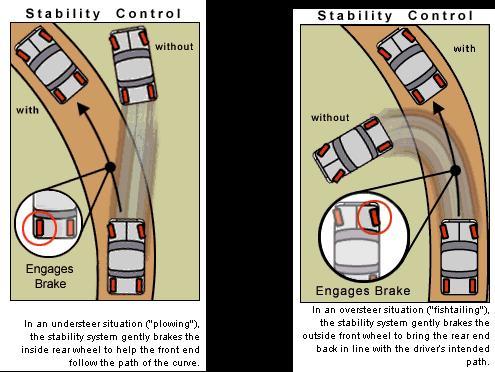
47
")
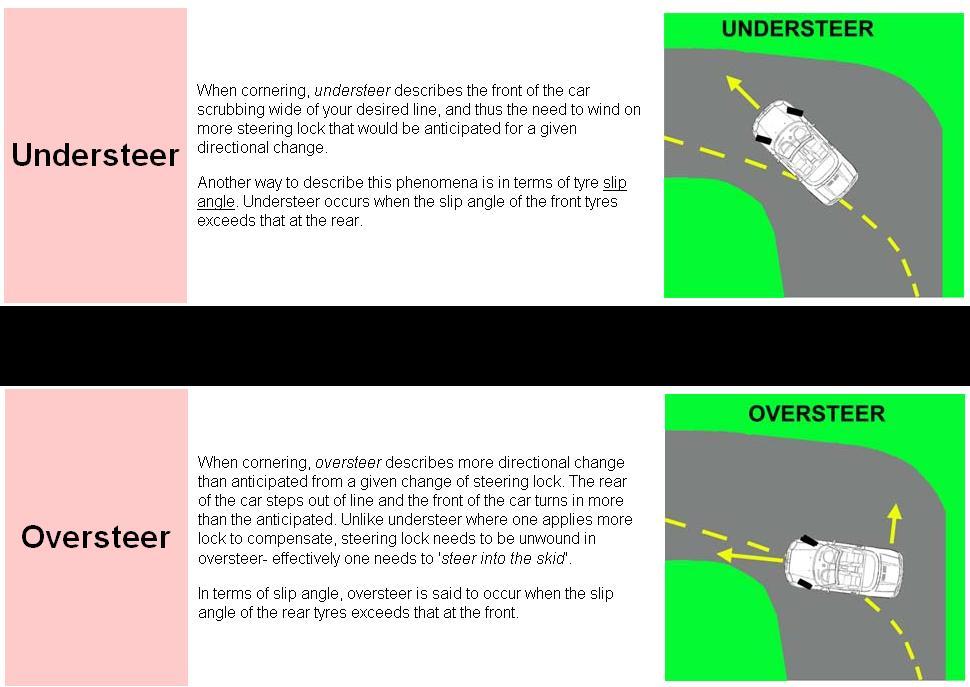
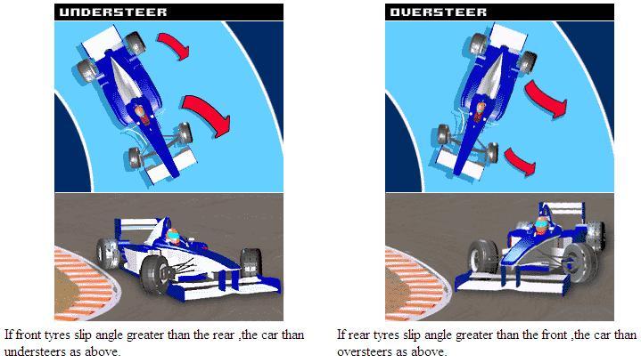
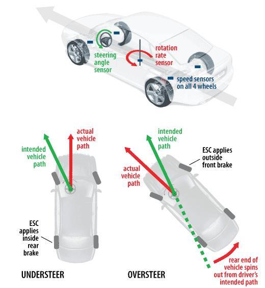
 Pressure INTENISFYING.")
48 36. Hydraulic control in the ABS modulator assembly has 3 modes of operation: 1) Pressure REDUCTION, 2) Pressure RETAINING, 3) Pressure INTENISFYING. (dump, hold, build)

49 The ABS system is self monitoring. Every time the ignition switch is placed in the ON/RUN position, the control module will perform a preliminary self check. The amber ABS light is illuminated during this test and will shut off if no problems are detected and no DTC s are stored. (Lamp Fault Codes)

50 A system malfunction will cause the control module to shut off or inhibit the ABS system however, normal power assisted braking remains.
51

52 37. Automatic control (ATC) systems apply the brakes when a drive wheel attempts to spin and lose traction. The goal is still controlling wheel slip rate. Treason Traction Technical

53 38. controls negative wheel slip and controls positive wheel spin. ABS, ATC

54 39. The EBCM and the PCM will work together to reduce engine during traction control mode. This can be accomplished through retarding spark timing, closing the throttle, limiting injector pulse width, increasing EGR flow, and up shifting the transmission. Torque Compression Horsepower


55 40. When ATC is actively controlling wheel spin, a lamp is illuminated on the cluster. *Green? Red Blue

56 41. Some traction control systems have a manual switch. The amber colored traction control system lamp on the instrument cluster will then be illuminated. Cut off Back off Slack off
 helps prevent")

57 42. Electronic control (ESC) helps prevent skids, swerves, and rollovers. Torque Stability Horsepower
58

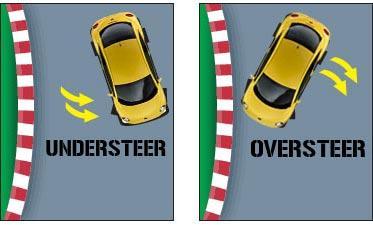
59 43. is a condition where the vehicle is slow to respond to steering changes. (plow)

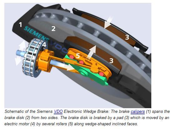
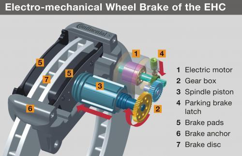
60 44. is a condition when the rear wheels try to swing around or fishtail. (loose)


61 45. is defined as the natural tendency of a vehicle to rotate on its vertical axis.

62 46. is the tendency of a vehicle to rotate on its horizontal axis. Pitch Roll Yaw


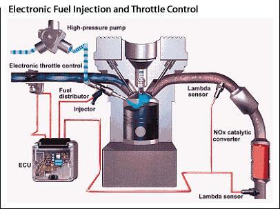
63 47. A vibration type senses understeer & oversteer signaling the need to correct yaw. Vibratory Gyroscope an instrument for determining the angular velocity of an object; contains vibrating parts that react to the object s rotation. There are bar and rotor types of vibratory gyroscope. The sensing element in the bar type is formed by several vibrating objects similar to the bars of a tuning fork. Gyroscope


64 48. ABS, ATC, and ECS Safety Precautions are listed on page

65 49. An important thing to remember about ABS service is to relieve pressure BEFORE performing any hydraulic system service. 28,000 psi of pressure may be present! Accumulator Decumulator Evaporator
66

67 50. A common method of depressurization is to the pedal 25 times with the ignition key off. Pump Stump Clump
.")
68 51. All ABS systems have some sort of,activated each time the ignition switch is turned on (KOEO). Self Test Written Test Blood Test

69 52. A solid (not flashing) ABS lamp indicates a has been detected and ABS is inhibited although normal power assisted braking is still present. A flashing lamp means repair ASAP! Problem Situation Fault

70 53. ABS fault codes cannot be until all faults have been corrected and the vehicle has been driven for a manufacturerspecified rate and distance. Erased Repaired Cleared


71 54. Many of the components in an ABS system are serviced by only. Rebuilding Reflashing Replacement


72 55. Brake is one area of service that will vary by manufacturer and system design. Bleeding Adjusting Replacing

73 56. The auto brake system continues to evolve with things like calipers, brake by wire, electronic wedge brakes, rain sensing brakes that apply to self dry and hill hold features. Electric Hydraulic Pneumatic
74
75

 Throttle Actuator")
76 In a drive by wire throttle control system, inlet air, fuel injection and ignition timing are also backed off during drive wheel slippage when ATC is energized. (manual cut off of ATC is available) Throttle Actuator Motor
77
78
79
80

81 It s wise to disconnect vehicle computers before arc welding on any vehicles.


82 Scanners may also energize systems for bleeding.
83
84
85
86
87
1. INTRODUCTION. Anti-lock Braking System
 1. INTRODUCTION Car manufacturers world wide are vying with each other to invent more reliable gadgets there by coming closer to the dream of the Advanced safety vehicle or Ultimate safety vehicle, on
Module 11: Antilock Brakes Systems
 ÂÂ ABS Brake System Antilock Brake System Operation Principles of ABS Braking ABS Master Cylinder Hydraulic Control Unit Wheel Speed Sensors ABS Electronic Control Unit Terms and Definitions Purposes for
ENRESO.WORLD. Traction Control System. Created by Istas René - enreso.world. Graduated in Autmotomotiv Technolgogys
 ENRESO.WORLD Traction Control System Created by Istas René - enreso.world Graduated in Autmotomotiv Technolgogys Traction Control (TCS) is an option that is often found on vehicles equipped with antilock
DIAGNOSIS AND TESTING
 206-09-1 Vehicle Dynamic Systems 206-09-1 DIAGNOSIS AND TESTING Anti-Lock Control Traction Control and Stability Assist Special Tool(s) Principles of Operation 73III Automotive Meter 105-R0057 or equivalent
DESCRIPTION & OPERATION
 DESCRIPTION & OPERATION ANTI-LOCK BRAKING 1998-99 BRAKES Anti-Lock/TCS - Corvette The Anti-Lock Brake System (ABS) and Traction Control System (TCS) increases vehicle control during severe deceleration
ANTI-LOCK BRAKES. Section 9. Fundamental ABS Systems. ABS System Diagram
 ANTI-LOCK BRAKES Fundamental ABS Systems Toyota Antilock Brake Systems (ABS) are integrated with the conventional braking system. They use a computer controlled actuator unit, between the brake master
Modern Auto Tech Study Guide Chapters 71 & 73 Pages Brake Systems 49 Points. Automotive Service
 Modern Auto Tech Study Guide Chapters 71 & 73 Pages 1369 1444 Brake Systems 49 Points 1. Automotive systems use to stop, slow or to hold the wheels from turning. Brake, Friction Brake, Fraction Brake,
2006 Mercedes-Benz USA, LLC. Chassis and Drivetrain 42
 Page 1 of 5 Chassis and Drivetrain 42 Brakes Anti-lock Brake System (ABS) 4-Wheel Electronic Traction Control System (4-ETS) Electronic Brake Proportioning (EBP) System Description The hydraulic pressure
ABS, 4-ETS and EBP BRAKES ANTI-LOCK BRAKE SYSTEM (ABS) 4-WHEEL ELECTRONIC TRACTION CONTROL SYSTEM (4-ETS) ELECTRONIC BRAKE PROPORTIONING (EBP)
 4-WHEEL ELECTRONIC TRACTION CONTROL SYSTEM (4-ETS) ELECTRONIC BRAKE PROPORTIONING (EBP)") 1 of 9 4/27/2008 7:52 AM Home Account Contact ALLDATA Log Out Help Select Vehicle New TSBs Technician's Reference Component Search: METRO TOYOTA OK 2002 Mercedes Benz Truck ML 320 (163.154) V6-3.2L (112.942)
1 of 9 4/27/2008 7:52 AM Home Account Contact ALLDATA Log Out Help Select Vehicle New TSBs Technician's Reference Component Search: METRO TOYOTA OK 2002 Mercedes Benz Truck ML 320 (163.154) V6-3.2L (112.942)
VEHICLE DYNAMICS CONTROL (VDC)
") VEHICLE DYNAMICS CONTROL (VDC) SYSTEM 1. Vehicle Dynamics Control (VDC) System A: GENERAL The vehicle dynamics control (VDC) system is a driver assist system which enhances vehicle s running stability
VEHICLE DYNAMICS CONTROL (VDC) SYSTEM 1. Vehicle Dynamics Control (VDC) System A: GENERAL The vehicle dynamics control (VDC) system is a driver assist system which enhances vehicle s running stability
ANTI-LOCK BRAKE SYSTEM - REAR WHEEL
 ANTI-LOCK BRAKE SYSTEM - REAR WHEEL 1994 Nissan Pickup 1994 BRAKES Nissan - Rear Anti-Lock Pathfinder, Pickup DESCRIPTION In 2WD mode, Rear Anti-Lock Brake System (RABS) helps the driver to maintain steering
TRACTION CONTROL SYSTEM (TCL)
") 35C-1 GROUP 35C TRACTION CONTROL SYSTEM (TCL) CONTENTS GENERAL DESCRIPTION 35C-2 DIAGNOSIS 35C-4 INTRODUCTION TO TRACTION CONTROL SYSTEM DIAGNOSIS 35C-4 TCL DIAGNOSTIC TROUBLESHOOTING STRATEGY 35C-4 DIAGNOSTIC
35C-1 GROUP 35C TRACTION CONTROL SYSTEM (TCL) CONTENTS GENERAL DESCRIPTION 35C-2 DIAGNOSIS 35C-4 INTRODUCTION TO TRACTION CONTROL SYSTEM DIAGNOSIS 35C-4 TCL DIAGNOSTIC TROUBLESHOOTING STRATEGY 35C-4 DIAGNOSTIC
SUBJECT: Automatic Stability Control with Traction Control System (ASC+T)
") Group 34 34 01 90 (2105) Woodcliff Lake, NJ October 1990 Brakes Service Engineering -------------------------------------------------------------------------------------------------------- SUBJECT: Automatic
Group 34 34 01 90 (2105) Woodcliff Lake, NJ October 1990 Brakes Service Engineering -------------------------------------------------------------------------------------------------------- SUBJECT: Automatic
Dealing with customer concerns related to electronic throttle bodies By: Bernie Thompson
 Dealing with customer concerns related to electronic throttle bodies By: Bernie Thompson In order to regulate the power produced from the gasoline internal combustion engine (ICE), a restriction is used
capacity due to increased traction; particularly advantageous on road surfaces
 42-800 Design and function of acceleration slip control (ASR I) A. General B. Driving with ASR I C. Overall function of ASR I D. Location of components E. Individual functions A. General The acceleration
 TRACTION CONTROL SYSTEM 1996 Toyota Supra 1995-96 BRAKES Traction Control Supra DESCRIPTION Toyota Traction Control (TRAC) system controls engine torque and braking of the driving wheels. TRAC system is
1998 E-Series Workshop Manual
 SECTION 206-09A: Anti-Lock Control Rear DIAGNOSIS AND TESTING Procedure revision date: 02/08/2000 Anti-Lock Control Refer to Wiring Diagrams Cell 42, Speed Control for schematic and connector information.
ANTI-LOCK BRAKING SYSTEM (ABS)
") 35B-1 GROUP 35B ANTI-LOCK BRAKING SYSTEM (ABS) CONTENTS GENERAL DESCRIPTION 35B-2 35B-5 INTRODUCTION TO 35B-5 ABS DIAGNOSTIC TROUBLESHOOTING STRATEGY 35B-5 DIAGNOSTIC FUNCTION 35B-6 DIAGNOSTIC TROUBLE
35B-1 GROUP 35B ANTI-LOCK BRAKING SYSTEM (ABS) CONTENTS GENERAL DESCRIPTION 35B-2 35B-5 INTRODUCTION TO 35B-5 ABS DIAGNOSTIC TROUBLESHOOTING STRATEGY 35B-5 DIAGNOSTIC FUNCTION 35B-6 DIAGNOSTIC TROUBLE
BRAKE CONTROL SYSTEM SECTION BRC CONTENTS BRAKES BRC-1 WITH VDC PRECAUTION... 5 PREPARATION... 9 SYSTEM DESCRIPTION...10
 BRAKES SECTION BRC A BRAKE CONTROL SYSTEM B C D CONTENTS E WITH VDC PRECAUTION... 5 PRECAUTIONS... 5 Precaution for Supplemental Restraint System (SRS) "AIR BAG" and "SEAT BELT PRE-TEN- SIONER"...5 Precaution
Document ID# Chevrolet/Geo Corvette
 Page 1 of 10 Document ID# 426762 1999 Chevrolet/Geo Corvette Print ABS Description Brake Pressure Modulator Valve (BPMV) FIGURE EBTCM/BPMV(c) (1) Electronic Brake and Traction Control
COASTAL BEND COLLEGE AUTOMOTIVE TECHNOLOGY SYLLABUS (rev. Fall 2012)
") COASTAL BEND COLLEGE AUTOMOTIVE TECHNOLOGY SYLLABUS (rev. Fall 2012) AUMT 1310: Automotive Brake Systems SEMESTER HOURS: 3 TEXTBOOK Automotive Technology A systems Approach COURSE DESCRIPTION; Operation
COASTAL BEND COLLEGE AUTOMOTIVE TECHNOLOGY SYLLABUS (rev. Fall 2012) AUMT 1310: Automotive Brake Systems SEMESTER HOURS: 3 TEXTBOOK Automotive Technology A systems Approach COURSE DESCRIPTION; Operation
1. Anti-lock Brake System (ABS)
") W1860BE.book Page 2 Tuesday, January 28, 2003 11:01 PM 1. Anti-lock Brake System () A: FEATURE The 5.3i type used in the Impreza has a hydraulic control unit, an control module, a valve relay and a motor
W1860BE.book Page 2 Tuesday, January 28, 2003 11:01 PM 1. Anti-lock Brake System () A: FEATURE The 5.3i type used in the Impreza has a hydraulic control unit, an control module, a valve relay and a motor
35C-1 GROUP 35C CONTENTS FEATURES... 35C-2 SYSTEM OPERATION... 35C-16 CONSTRUCTION DESCRIPTION... 35C-5
 35C-1 GROUP 35C CONTENTS FEATURES.................... 35C-2 SYSTEM OPERATION............ 35C-16... 35C-5 35C-2 FEATURES Anti-skid Brake System/Active Stability System (ABS/active stability system) is available
TCU 1) CONNECTOR INFORMATION 2) CONNECTOR IDENTIFICATION SYMBOL & PIN NUMBER POSITION CIRCUIT ACTYON
 CONNECTOR INFORMATION 2) CONNECTOR IDENTIFICATION SYMBOL & PIN NUMBER POSITION CIRCUIT ACTYON") 311001 017 311001 TCU 1) CONNECTOR INFORMATION 2) CONNECTOR IDENTIFICATION SYMBOL & PIN NUMBER POSITION 018 311001 (3) DESCRIPTION A. ION (BTRA) M74 4WD AUTOMATIC TRANSMISSION The ION (BTR) Four Speed
311001 017 311001 TCU 1) CONNECTOR INFORMATION 2) CONNECTOR IDENTIFICATION SYMBOL & PIN NUMBER POSITION 018 311001 (3) DESCRIPTION A. ION (BTRA) M74 4WD AUTOMATIC TRANSMISSION The ION (BTR) Four Speed
SECTION Anti-Lock Brake System (ABS) and Stability Control
 and Stability Control") 206-09-i Anti-Lock Brake System (ABS) and Stability Control 206-09-i SECTION 206-09 Anti-Lock Brake System (ABS) and Stability Control CONTENTS PAGE DIAGNOSIS AND TESTING Anti-Lock Control... 206-09-2
206-09-i Anti-Lock Brake System (ABS) and Stability Control 206-09-i SECTION 206-09 Anti-Lock Brake System (ABS) and Stability Control CONTENTS PAGE DIAGNOSIS AND TESTING Anti-Lock Control... 206-09-2
Antilock Brakes, Vehicle Stability Control, and Power Assist
 C H A P T E R 1 6 Antilock Brakes, Vehicle Stability Control, and Power Assist Chapter Objectives At the conclusion of this chapter you should be able to: Explain the purpose and operation of antilock
Diagnostic Trouble Code (DTC) List - Vehicle
 List - Vehicle") Document ID# 850406 2002 Pontiac Firebird Diagnostic Trouble Code (DTC) List - Vehicle DTC DTC 021 and/or 031 DTC 022 and/or 032 DTC 023 or 033 DTC 24/34 DTC 025 and/or 035 DTC 041 DTC 042 DTC 043 DTC
Document ID# 850406 2002 Pontiac Firebird Diagnostic Trouble Code (DTC) List - Vehicle DTC DTC 021 and/or 031 DTC 022 and/or 032 DTC 023 or 033 DTC 24/34 DTC 025 and/or 035 DTC 041 DTC 042 DTC 043 DTC
Chapter 33 Fundamentals of Hydraulic and Air-Over-Hydraulic Braking Systems
 Chapter 33 Fundamentals of Hydraulic and Air-Over-Hydraulic Braking Systems Introduction Vehicle s braking system must meet the following requirements: To adequately and safely reduce a vehicle s speed,
System overview. Introduction. Copyright 2004 Volvo Car Corporation. All rights reserved.
 "VCC141172 EN 20090206" 1(40) System overview Introduction The Mark25 brake control system The Mark 25 brake control system with the brake control module (BCM) is an electronic control system which prevents
ATASA 5 th. ATASA 5 TH Study Guide Chapter 27 Pages Ignition Systems 68 Points. Please Read the Summary
 ATASA 5 TH Study Guide Chapter 27 Pages 810 835 68 Points Please Read the Summary Before We Begin Keeping in mind the Career Cluster of Transportation, Distribution & Logistics Ask yourself: What careers
 Page 1 of 23 593: Brake control system V70 (00-08), 2004, B5244S2, M56, L.H.D, YV1SW65S241436824, 436824 16/7/2018 PRINT 593: Brake control system ABS control ABS function Active yaw control Active yaw
The following rear differential is provided for the off-road package models. BD20B (with Differential Lock Actuator)
") 6 4RUNNER NEW FEATURES NEW FEATURES DIFFERENTIAL (OFF-ROAD PACKAGE MODELS) 1. General The following rear differential is provided for the off-road package models. Rear Differential Lock Actuator 233CH46
6 4RUNNER NEW FEATURES NEW FEATURES DIFFERENTIAL (OFF-ROAD PACKAGE MODELS) 1. General The following rear differential is provided for the off-road package models. Rear Differential Lock Actuator 233CH46
1. BRAKE SYSTEM GENERAL INFORMATION
 4890-01 08-3 1. BRAKE SYSTEM GENERAL INFORMATION Front Disc 1) FRONT BRAKE For the front brake system, the ventilated disc type is applied regardless of the ABS/ system installation. Two 43 mm diameter
ABS Operator s Manual
 ABS Operator s Manual Bendix Antilock Brake Systems With optional advanced antilock braking features: Automatic Traction Control (ATC) and RSP Roll Stability System Read, understand and follow the information
ANTI-LOCK BRAKE SYSTEM. Seminar by K.JAYAKISHORE GRIET HYDERABAD
 ANTI-LOCK BRAKE SYSTEM Seminar by K.JAYAKISHORE GRIET HYDERABAD INTRODUCTION An anti-lock braking system (ABS) is a safety system on motor vehicles which prevents the wheels from locking while braking.
FUEL INJECTION SYSTEM - MULTI-POINT
 FUEL INJECTION SYSTEM - MULTI-POINT 1988 Jeep Cherokee 1988 Electronic Fuel Injection JEEP MULTI-POINT 4.0L Cherokee, Comanche, Wagoneer DESCRIPTION The Multi-Point Electronic Fuel Injection (EFI) system
codigos error OBD2 genericos
 ucables.com Tecnologias de diagnostico y reparacion de automoviles C - Generic OBD-II Chassis Codes C0000 - Vehicle Speed Information Circuit Malfunction C0035 - Left Front Wheel Speed Circuit Malfunction
Charging Systems. ATASA 5 th. ATASA 5 TH Study Guide Chapter 19 Pages Charging Systems 42 Points. Please Read The Summary
 ATASA 5 TH Study Guide Chapter 19 Pages 571 595 42 Points Please Read The Summary 1. The primary purpose of the charging system is to the battery with a constant and relatively low charge after it has
INSTALLATION INSTRUCTIONS
 INSTALLATION INSTRUCTIONS BIG ROTOR / CALIPER RELOCATION FRONT KITS SUM-BK1422, BK1423, BK1424 1999-2006 GM 1/2 Ton Trucks & SUVs Thank you for choosing SUMMIT RACING for your braking needs. Pleases take
TECHNICAL PAPER 1002 FT. WORTH, TEXAS REPORT X ORDER
 I. REFERENCE: 1 30 [1] Snow Engineering Co. Drawing 80504 Sheet 21, Hydraulic Schematic [2] Snow Engineering Co. Drawing 60445, Sheet 21 Control Logic Flow Chart [3] Snow Engineering Co. Drawing 80577,
Anti Locking Brakes. Seminar by JYOTI RANJAN NAYAK. Regd no:
 Anti Locking Brakes Seminar by JYOTI RANJAN NAYAK Regd no: 0501227541 Introduction An anti-lock braking system (ABS) is a safety system on motor vehicles which prevents the wheels from locking while braking.
ANTI-LOCK BRAKING SYSTEM (ABS)
") 35B-1 GROUP 35B ANTI-LOCK BRAKING SYSTEM (ABS) CONTENTS GENERAL DESCRIPTION......... 35B-2................ 35B-4 INTRODUCTION TO ANTI-LOCK BRAKING SYSTEM DIAGNOSIS................ 35B-4 ABS DIAGNOSTIC
35B-1 GROUP 35B ANTI-LOCK BRAKING SYSTEM (ABS) CONTENTS GENERAL DESCRIPTION......... 35B-2................ 35B-4 INTRODUCTION TO ANTI-LOCK BRAKING SYSTEM DIAGNOSIS................ 35B-4 ABS DIAGNOSTIC
35A-1 SERVICE BRAKES CONTENTS BASIC BRAKE SYSTEM ANTI-SKID BRAKING SYSTEM (ABS) <2WD> ACTIVE STABILITY CONTOROL (ASC) SYSTEM
 <2WD> ACTIVE STABILITY CONTOROL (ASC) SYSTEM") 35A-1 SERVICE BRAKES CONTENTS BASIC BRAKE SYSTEM... 35A ANTI-SKID BRAKI SYSTEM (ABS) ... 35B ACTIVE STABILITY CONTOROL (ASC) SYSTEM... 35C 35A-2 BASIC BRAKE SYSTEM General/On-vehicle Service GENERAL
35A-1 SERVICE BRAKES CONTENTS BASIC BRAKE SYSTEM... 35A ANTI-SKID BRAKI SYSTEM (ABS) ... 35B ACTIVE STABILITY CONTOROL (ASC) SYSTEM... 35C 35A-2 BASIC BRAKE SYSTEM General/On-vehicle Service GENERAL
The parking brake is an electrically actuated system that operates drum brakes integrated into the rear brake discs. The
 Page 1 of 15 Published: Oct 22, 2004 Parking Brake COMPONENT LOCATIONS Item Part Number Description 1 Clutch pedal position sensor (manual transmission models only) 2 Parking brake indicators (all except
ASE Practice Test A5 Brakes
 ASE Practice Test A5 Brakes Hydraulic System Diagnosis and Repair 1) A spongy brake pedal may be caused by: a. ABS Diagnostic Trouble Code set b. Frozen caliper piston c. Defective metering valve d. Air
Installation Guide. Installing the FRK Hydraulic Compact Unit (HCU) with Parking Brake Valve on International School Buses
 with Parking Brake Valve on International School Buses") Revised 09-18 Installation Guide Revised 1 Technical 09-18 Bulletin Installing the FRK 08-10086 Hydraulic Compact Unit (HCU) with Parking Brake Valve on International School Buses Hazard Alert Messages
Revised 09-18 Installation Guide Revised 1 Technical 09-18 Bulletin Installing the FRK 08-10086 Hydraulic Compact Unit (HCU) with Parking Brake Valve on International School Buses Hazard Alert Messages
How Regenerative Braking Works
 Feature How Regenerative Braking Works The regenerative braking systems on Nissan hybrid vehicles can be confusing and misunderstood. Let s take a look at how these systems really work. 26 Nissan TechNews
INSTALLATION INSTRUCTIONS
 INSTALLATION INSTRUCTIONS BIG ROTOR / CALIPER RELOCATION REAR KIT SUM-BK1423 1999-2009 GM 1/2 Ton Trucks & SUVs Thank you for choosing SUMMIT RACING for your braking needs. Pleases take the time to read
SD Bendix EC-14 AntiLock Controller Assembly DESCRIPTION GENERAL MOUNTING PHYSICAL
 Bendix EC-14 AntiLock Controller Assembly SD-13-4784 30 PIN WIRE HARNESS CONNECTOR MOUNTING HOLES (4) DIAGSTICS WINDOW DESCRIPTION GENERAL Bendix trailer antilock systems utilizing the EC-14 electronic
BASIC BRAKE SYSTEM GROUP 35A 35A-1 CONTENTS GENERAL DESCRIPTION... 35A-3 BASIC BRAKE SYSTEM DIAGNOSIS 35A-6
 35A-1 GROUP 35A BASIC BRAKE SYSTEM CONTENTS GENERAL DESCRIPTION......... 35A-3 DIAGNOSIS 35A-6 INTRODUCTION..................... 35A-6 DIAGNOSTIC TROUBLESHOOTING STRATEGY......................... 35A-6
GROUP 35A 35A-1 CONTENTS GENERAL DESCRIPTION... 35A-3 BASIC BRAKE SYSTEM DIAGNOSIS 35A-6 HYDRAULIC BRAKE BOOSTER (HBB) DIAGNOSIS...
 DIAGNOSIS...") 35A-1 GROUP 35A CONTENTS GENERAL DESCRIPTION......... 35A-3 DIAGNOSIS 35A-6 INTRODUCTION..................... 35A-6 DIAGNOSTIC TROUBLESHOOTING STRATEGY......................... 35A-6 SYMPTOM CHART...................
35A-1 GROUP 35A CONTENTS GENERAL DESCRIPTION......... 35A-3 DIAGNOSIS 35A-6 INTRODUCTION..................... 35A-6 DIAGNOSTIC TROUBLESHOOTING STRATEGY......................... 35A-6 SYMPTOM CHART...................
ANTI-LOCK BRAKING SYSTEM (ABS)
") 35B-1 GROUP 35B ANTI-LOCK BRAKING SYSTEM (ABS) CONTENTS GENERAL DESCRIPTION......... 35B-2 ANTI-SKID BRAKING SYSTEM (ABS) DIAGNOSIS.................... 35B-3 INTRODUCTION TO ANTI-LOCK BRAKE SYSTEM DIAGNOSIS................
35B-1 GROUP 35B ANTI-LOCK BRAKING SYSTEM (ABS) CONTENTS GENERAL DESCRIPTION......... 35B-2 ANTI-SKID BRAKING SYSTEM (ABS) DIAGNOSIS.................... 35B-3 INTRODUCTION TO ANTI-LOCK BRAKE SYSTEM DIAGNOSIS................
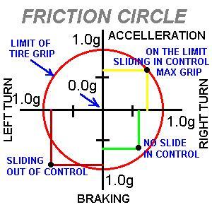
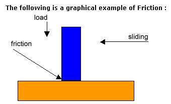
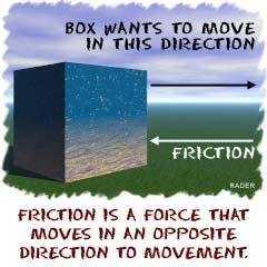
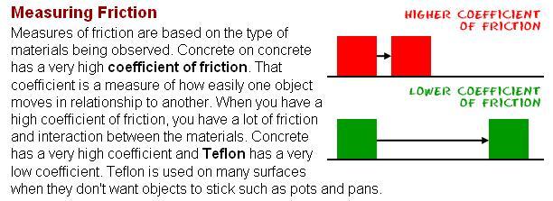
4.4. Forces Applied to Automotive Technology. The Physics of Car Tires
 Forces Applied to Automotive Technology Throughout this unit we have addressed automotive safety features such as seat belts and headrests. In this section, you will learn how forces apply to other safety
ATASA 5 th. Wheel Alignment. Please Read The Summary. ATASA 5 TH Study Guide Chapter 47 Pages: Wheel Alignment 64 Points
 ATASA 5 TH Study Guide Chapter 47 Pages: 1403 1423 64 Points Please Read The Summary Before We Begin Keeping in mind the Career Cluster of Transportation, Distribution & Logistics Ask yourself: What careers
Motronic September 1998
 The Motronic 1.8 engine management system was introduced with the 1992 Volvo 960. The primary difference between this Motronic system and the previous generation of Volvo LH-Jetronic engine management
G - TESTS W/CODES - 2.2L
 G - TESTS W/CODES - 2.2L 1994 Toyota Celica 1994 ENGINE PERFORMANCE Toyota 2.2L Self-Diagnostics Celica INTRODUCTION If no faults were found while performing F - BASIC TESTING, proceed with self-diagnostics.
International Medium Duty Full Power Hydraulic Brakes
 A N AV I S TA R C O M PA N Y International Medium Duty Full Power Hydraulic Brakes Study Guide TMT-040701 Study Guide International Medium Duty Full Power Hydraulic Brakes TMT-040701 2007 International
ON BOARD DIAGNOSTIC SYSTEM DESCRIPTION Self-diagnosis. Self-diagnosis BR-44 FUNCTION SELF-DIAGNOSIS PROCEDURE ABS
 Self-diagnosis ON BOARD DIAGNOSTIC SYSTEM DESCRIPTION Self-diagnosis FUNCTION NABR0095 NABR0095S01 When a problem occurs in the, the warning lamp on the instrument panel comes on. To start the self-diagnostic
Vehicle makes models and variants known or believed to be using this vehicle system, required diagnostic lead and degree of known compatibility.
 WABCO D TYPE (P38 NRR)-System Overview This is a small black ECU which replaced the Wabco C type during the 1999 update to the P38. If the vehicle has White indicators and/ or Air Bags in the seats, it
EMISSION CONTROL SYSTEM
 XJ EMISSION CONTROL SYSTEM 25-1 EMISSION CONTROL SYSTEM CONTENTS EXHAUST EMISSION CONTROLS 2.5L DIESEL ENGINE... 6 ON-BOARD DIAGNOSTICS 2.5L DIESEL ENGINE... 1 ON-BOARD DIAGNOSTICS 2.5L DIESEL ENGINE INDEX
ELECTRONIC CONTROL SYSTEM. 1. General CH-16 CHASSIS - U340E AUTOMATIC TRANSAXLE
 CH-16 ELECTRONIC CONTROL SYSTEM 1. General The electronic control system of the U340E automatic transaxle consists of the controls listed below. System Clutch Pressure Control (See page CH-20) Line Pressure
C6 Corvette DIC Codes
 C6 Corvette DIC Codes B0159 Outside Air Temp Sensor B2910 Steering Column Lock Password Incorrect B0164 Pass Compartment Temp Sensor B2981 Right Front Door Handle Switch B0174 Output Air Temp Sensor 1
FOUR-WHEEL ANTI-LOCK BRAKE SYSTEM (4ABS)
") 35B-1 GROUP 35B FOUR-WHEEL ANTI-LOCK BRAKE SYSTEM (4ABS) CONTENTS GENERAL INFORMATION 35B-2 35B-6 SENSOR 35B-6 ACTUATORS 35B-6 ABS-ECU 35B-7 35B-2 The ABS that ensures directional stability and controllability
35B-1 GROUP 35B FOUR-WHEEL ANTI-LOCK BRAKE SYSTEM (4ABS) CONTENTS GENERAL INFORMATION 35B-2 35B-6 SENSOR 35B-6 ACTUATORS 35B-6 ABS-ECU 35B-7 35B-2 The ABS that ensures directional stability and controllability
Variable Geometry Turbocharger (VGT) Actuator Connector
 Actuator Connector") Page 1 of 5 Year = 2006 Model = F-Super Duty Engine = VIN = IDS Version = 77A.05 (IDS-77A.05) Variable Geometry Turbocharger (VGT) Output Circuit Function The VGT actuator is a variable position valve
Page 1 of 5 Year = 2006 Model = F-Super Duty Engine = VIN = IDS Version = 77A.05 (IDS-77A.05) Variable Geometry Turbocharger (VGT) Output Circuit Function The VGT actuator is a variable position valve
Unit HV04K Knowledge of Heavy Vehicle Chassis Units and Components
 Assessment Requirements Unit HV04K Knowledge of Heavy Vehicle Chassis Units and Components Content: Chassis layouts i. types of chassis ii. axle configurations iii. rear steered axles iv. self-steered
TroubleCodes.net- engine & OBD2 Trouble Codes and Technical info & Tool Store.
 Page 1 sur 8 advertisement Articles / SAFETY / TOOL STORE!! / BAT Support / Search / Help / Guestbook / About Us / Contact Us Forums Navigation Links & Technical Trouble Codes Sunday, January 23, 2005
Hydro-Max Hydraulic Brake Booster and Master Cylinder. Technical Manual
 Hydro-Max Hydraulic Brake Booster and Master Cylinder Technical Manual * 5+0 Important Service Notes The information in this publication was current at the time of printing. The information presented in
ABS keeps the vehicle steerable, even during an emergency braking
 ABS keeps the vehicle steerable, even during an emergency braking under all road conditions 1 Contents! Safety systems in vehicles! Why do you need ABS?! How does ABS work?! What are the benefits of ABS?!
definition Retarders definition driving tip chapter 2 heavy vehicle braking Using retarders
 chapter 2 heavy vehicle braking Brake fade occurs when your brakes stop working properly because they're overheated. Your vehicle takes longer to stop, or may not stop at all if you haven't properly controlled
3. Engine Control System Diagram
 ENGINE - 2UZ-FE ENGINE 59 3. Engine Control System Diagram Ignition Switch Fuel Pump Relay Fuel Pump Resister Circuit Opening Fuel Relay Filter Intake Temp. Mass Air Flow Meter Throttle Position Fuel Pump
2001 Chevrolet Corvette ACCESSORIES & EQUIPMENT Cruise Control Systems - Corvette
 2001 ACCESSORIES & EQUIPMENT Cruise Control Systems - Corvette DESCRIPTION Cruise control is a speed control system that maintains a desired vehicle speed under normal driving conditions. Steep grades
SPEED CONTROL SYSTEM
 DN SPEED CONTROL SYSTEM 8H - 1 SPEED CONTROL SYSTEM TABLE OF CONTENTS page AND SPEED CONTROL SYSTEM...1 SPEED CONTROL SERVO....2 SPEED CONTROL SOLENOID CIRCUITS...2 SPEED CONTROL SWITCHES...2 BRAKE LAMP
Automatic drain valves
 driving commercial vehicles If you notice more than a few drops of water when you drain the supply reservoir, the air dryer or compressor may need servicing. fast fact Even if the air brake system includes
16 Introduction to DSC
 Lateral Acceleration Sensor (Bosch 5.3) This new sensor is a major contributor of the expanded capabilities of DSC III. It is located under the drivers seat but mounted on the vertical surface of the inner
1993 ENGINE PERFORMANCE Volkswagen Self-Diagnostics. EuroVan
 Article Text Saturday, March 18, 2000 10:32PM ARTICLE BEGINNING 1993 ENGINE PERFORMANCE Volkswagen Self-Diagnostics EuroVan INTRODUCTION If no faults were found while performing preliminary inspection
GF42.47-P-0001FLM Adaptive brake (ABR), function
, function") GF42.47-P-0001FLM Adaptive brake (ABR), function 14.1.13 MODEL 212 (except 212.095/098/298) as of model year 2014 Function requirements, general the engine is running or has been switched off by the ECO
GF42.47-P-0001FLM Adaptive brake (ABR), function 14.1.13 MODEL 212 (except 212.095/098/298) as of model year 2014 Function requirements, general the engine is running or has been switched off by the ECO
CONDITIONS FOR RUNNING THE DTC
 SYSTEM DESCRIPTION The powertrain control module (PCM) uses information from the crankshaft position (CKP) sensor and the camshaft position (CMP) sensor in order to determine when an engine misfire is
POWER TRAIN 2-1 CONTENTS AYC SYSTEM... 9 CLUTCH... 2 MANUAL TRANSMISSION... 3 PROPELLER SHAFTS... 4 FRONT AXLE... 5 REAR AXLE... 6
 2-1 POWER TRAIN CONTENTS CLUTCH................................ 2 MANUAL TRANSMISSION............... 3 Transmission Control....................... 3 PROPELLER SHAFTS................... 4 FRONT AXLE...........................
NATEF Task Area A 5 Brake Systems
 NATEF Task Area A 5 Brake Systems A. General Brake System Diagnosis B. Hydraulic System Diagnosis & Repair C. Drum Brake Diagnosis & Repair D. Disc Brake Diagnosis & Repair E. Power Assist Diagnosis &
SERVICE MANUAL. Common Rail System for HINO J08C/J05C Type Engine Operation. For DENSO Authorized ECD Service Dealer Only
 For DENSO Authorized ECD Service Dealer Only Diesel Injection Pump No. E-03-03 SERVICE MANUAL Common Rail System for HINO J08C/J05C Type Engine Operation June, 2003-1 00400024 GENERAL The ECD-U2 was designed
Read on to find out more about each component of the Star Safety System and how it can be of benefit to you.
 All 2011 Toyota models come standard with the Star Safety System. This integration of active safety features is designed to protect occupants by helping drivers avoid accidents in the first place. The
DASH RETRIEVED FAULT CODES C ONVENTIONAL FS65 SAF T LINER C2, C2E H YBRID SAF T LINER HDX, HD, ER SAF T LINER EF, EFX A LL Y EARS
 DASH RETRIEVED FAULT CODES C ONVENTIONAL FS65 SAF T LINER C2, C2E H YBRID SAF T LINER HD, HD, ER SAF T LINER EF, EF A LL Y EARS PAGE INTENTIONALLY LEFT BLANK TABLE OF CONTENTS EARLY PRODUCTS: J1587/J1708
ANTI-LOCK BRAKING SYSTEM (ABS)
") 35B-1 GROUP 35B ANTI-LOCK BRAKING SYSTEM (ABS) CONTENTS GENERAL DESCRIPTION 35B-2 DIAGNOSIS 35B-4 INTRODUCTION TO ANTI-LOCK BRAKING SYSTEM DIAGNOSIS 35B-4 ABS DIAGNOSTIC TROUBLESHOOTING STRATEGY 35B-4
35B-1 GROUP 35B ANTI-LOCK BRAKING SYSTEM (ABS) CONTENTS GENERAL DESCRIPTION 35B-2 DIAGNOSIS 35B-4 INTRODUCTION TO ANTI-LOCK BRAKING SYSTEM DIAGNOSIS 35B-4 ABS DIAGNOSTIC TROUBLESHOOTING STRATEGY 35B-4
Ford 8, 9 Small Bearing Installation Instructions Rear Disc Conversion
 Ford 8, 9 Small Bearing Installation Instructions Rear Disc Conversion This kit is for Ford 9 rear axles with the small (2.835 ) style bearing and Ford 8 rear ends. This kit is designed to work with axles
EMISSION CONTROL SYSTEM
 XJ EMISSION CONTROL SYSTEM 25-1 EMISSION CONTROL SYSTEM TABLE OF CONTENTS ON-BOARD DIAGNOSTICS 2.5L DIESEL ENGINE... 1 EXHAUST EMISSION CONTROLS 2.5L DIESEL ENGINE... 6 ON-BOARD DIAGNOSTICS 2.5L DIESEL
Diagnostic Trouble Code (DTC) memory, checking and erasing
 memory, checking and erasing") Page 1 of 49 01-12 Diagnostic Trouble Code (DTC) memory, checking and erasing Check DTC Memory (function 02) - Connect VAS5051 tester Page 01-7 and select vehicle system "01 - Engine electronics". Engine
Page 1 of 49 01-12 Diagnostic Trouble Code (DTC) memory, checking and erasing Check DTC Memory (function 02) - Connect VAS5051 tester Page 01-7 and select vehicle system "01 - Engine electronics". Engine
ANTI-LOCK BRAKE SYSTEM
 ANTI-LOCK BRAKE SYSTEM 1992 Infiniti G20 1990-92 BRAKES Infiniti Anti-Lock Brake System Infiniti; G20, M30, Q45 DESCRIPTION & OPERATION The Anti-Lock Brake System (ABS) prevents wheel lock-up during abrupt
FOUR-WHEEL ANTI-LOCK BRAKE SYSTEM (4ABS)
") 35B-1 GROUP 35B FOUR-WHEEL ANTI-LOCK BRAKE SYSTEM (4ABS) CONTENTS GENERAL DESCRIPTION......... 35B-2 SENSORS..................... 35B-6 BRAKE MODULATOR (ABS-ECU).. 35B-9 SYSTEM OPERATION............ 35B-10
35B-1 GROUP 35B FOUR-WHEEL ANTI-LOCK BRAKE SYSTEM (4ABS) CONTENTS GENERAL DESCRIPTION......... 35B-2 SENSORS..................... 35B-6 BRAKE MODULATOR (ABS-ECU).. 35B-9 SYSTEM OPERATION............ 35B-10
Introduction and Overview to Friction Brakes. Course 105 PREVIEW ONLY PARTICIPANT GUIDE
 Introduction and Overview to Friction Brakes Course 105 PARTICIPANT GUIDE Table of Contents How to Use the Participant Guide... ii MODULE 1...1 General Principles and Terminology...1 1-1 Safety Review...2
Brake System Fundamentals Chapter 71 Name Date Period
 Brake System Fundamentals Chapter 71 Name Date Period Basic Brake System Matching 1. Metal tubing and rubber hose that transmit pressure to the wheel brake assemblies. 2. Mechanical system for applying
DIAGNOSTIC TROUBLE CODES: TRANSFER CASE MOTOR
 2008 02 Trailblazer/Envoy, 2008 03 Isuzu Ascender DTC-C0306: Motor A or B Circuit Failure Diagnostic Trouble Code C0306 is set once the Transfer Case Control Module detects an open, short-to-ground, or
NATEF Hands-On Competency Checklist A5 Auto Brakes
 NATEF Hands-On Checklist A5 Auto Brakes Student Name: Date: Instructor: Suggested Ratings: 5 Mastered competency. Able to perform all elements of task successfully and independently without supervision.
ABS. Prof. R.G. Longoria Spring v. 1. ME 379M/397 Vehicle System Dynamics and Control
 ABS Prof. R.G. Longoria Spring 2002 v. 1 Anti-lock Braking Systems These systems monitor operating conditions and modify the applied braking torque by modulating the brake pressure. The systems try to
Powertrain DTC Summaries EOBD
 Powertrain DTC Summaries Quick Reference Diagnostic Guide Jaguar S-TYPE V6, V8 N/A and V8 SC 2002.5 Model Year Refer to pages 2 9 for important information regarding the use of Powertrain DTC Summaries.
Code 32. Diagnostic Trouble Code 32
 Code 32 Diagnostic Trouble Code 32 EGR Solenoid Circuit CIRCUIT DESCRIPTION The ECM operates a solenoid to control the Exhaust Gas Recirculation (EGR) valve. This solenoid is normally close EGR valve.
Isuzu. Chapter Testing Engine and Transmission Systems Engine And Transmission Code Reading Connectors and Locations
 Chapter 10 Isuzu This chapter contains information for testing Isuzu vehicles with the Asian Import Vehicle Communication Software (VCS). The following Isuzu systems may be available for testing: Engine
ATASA 5 th. Detailed Diagnosis & Sensors. Please Read The Summary
 ATASA 5 TH Study Guide Chapter 26 Pages 764 809 51 Points Please Read The Summary 1. Many different sensors are involved in the overall driveability of a vehicle. Input Processing Output Electronic Engine
7. ETCS-i (Electronic Throttle Control System-intelligent)
") 5 7. ETCS-i (Electronic System-intelligent) General The ETCS-i is used, providing excellent throttle control in all the operating ranges. In the new 1GR-FE engine, the accelerator cable has been discontinued,
5 7. ETCS-i (Electronic System-intelligent) General The ETCS-i is used, providing excellent throttle control in all the operating ranges. In the new 1GR-FE engine, the accelerator cable has been discontinued,
10.1 Electronic Stability Program (ESP) and Speed-sensitive Power Steering (SPS) Contents
 and Speed-sensitive Power Steering (SPS) Contents") 10.1 lectronic Stability Program (SP) and Speed-sensitive Power Steering (SPS) Contents 10.1 Models 129 (with engine 104, 119) up to M.Y. 1999, Model 129 (with engine 120), 140, 210 as of M.Y. 1996 Page
10.1 lectronic Stability Program (SP) and Speed-sensitive Power Steering (SPS) Contents 10.1 Models 129 (with engine 104, 119) up to M.Y. 1999, Model 129 (with engine 120), 140, 210 as of M.Y. 1996 Page
Safe Braking on the School Bus Advanced BrakingTechniques and Practices. Reference Guide and Test by Video Communications
 Safe Braking on the School Bus Advanced BrakingTechniques and Practices Reference Guide and Test by Video Communications Introduction Brakes are considered one of the most important items for school bus