Chapter 33 Fundamentals of Hydraulic and Air-Over-Hydraulic Braking Systems
|
|
|
- Kelley Shepherd
- 5 years ago
- Views:
Transcription

1 Chapter 33 Fundamentals of Hydraulic and Air-Over-Hydraulic Braking Systems
2 Introduction Vehicle s braking system must meet the following requirements: To adequately and safely reduce a vehicle s speed, when required to do so To maintain vehicle speed on downhill gradients To be able to hold vehicle stationary, even when on gradient and driver is away from the vehicle
3 Fundamental Configurations for Hydraulic Braking Systems Hydraulic brake systems: same basic components augmented by one of two power assist or boost methods. Vacuum booster: medium-duty commercial vehicles; lower cost factor for vehicle range; engine of choice is diesel engine. Hydroboost: Class 4 to Class 6 commercial vehicles; uses pressurized hydraulic fluid to provide brake power assist.
4 Fundamental Configurations for Hydraulic Braking Systems Air-Over-Hydraulic Braking Systems Use air compressor to provide power assistance over hydraulic components to braking system Hydraulically controlled system: compressor, air dryer reservoir tanks, lines Air treadle (foot) valve: sends air pressure directly or indirectly to air boosters that actuate hydraulic master cylinders to apply the brakes
5 Fundamental Configurations for Hydraulic Braking Systems Hydraulic Braking Systems Brake pedal or lever Pushrod (actuating rod) Master cylinder assembly containing piston assembly (one or two pistons, series of seals, O-rings, fluid reservoir) Reinforced hydraulic lines Disc brake assemblies Filled with glycol-ether-based brake fluid
6 Fundamental Configurations for Hydraulic Braking Systems
7 Fundamental Configurations for Hydraulic Braking Systems Hydraulic Braking Systems When brake pedal pressed, pushrod exerts force on piston(s) in master cylinder, causing fluid from brake fluid reservoir to flow into pressure chamber through compensating port. Results in increase in pressure of entire system Forces fluid through hydraulic lines toward disc brake calipers and drum brake wheel cylinders, where fluid force acts upon pistons
8 Fundamental Configurations for Hydraulic Braking Systems Hydraulic Braking Systems Brake caliper pistons apply force to brake pads and brake shoes to push them against spinning rotor or drum. Friction between pads/shoes and rotating surfaces generates braking torque to slow vehicle. Release of brake pedal/lever allows spring(s) to return master piston(s) back into position. Designed as closed system
9 Foundation Components of Hydraulic Braking Systems Drum Brakes Drum arrangements used on rear wheels, with disc brakes on front in disc/drum configuration. Drum brake has two brake shoes with attached lining made of friction material. Main advantage: shoe mountings designed to assist their own operation (self-energizing)
10 Foundation Components of Hydraulic Braking Systems Drum Brakes Main disadvantage: friction area almost entirely covered by lining; heat conducted through drum to reach outside air to cool. Brake fade: gradual loss of brake stopping power during prolonged or strenuous use. Very high temperatures occur at brake drum; causes deterioration in frictional value of lining or pad material.
11 Foundation Components of Hydraulic Braking Systems Brake Shoe Configurations and Actuation Mechanisms Single-leading-shoe drum brake (SLS): leading/trailing shoe drum brake arrangement; basic drum brake design Found on rear wheels of vehicles Term leading/trailing : one shoe leading, that is, moving with direction of drum s rotation and exhibiting self-applying, or selfservo, effect.
12 Foundation Components of Hydraulic Braking Systems Brake Shoe Configurations and Actuation Mechanisms Other shoe is trailing : moving against direction of rotation, and being thrown off drum s friction surface and not retarding drum effectively. Self-servo effect arises in two-leading-shoe arrangement because leading shoes are dragged into brake drum s friction surface and achieve maximum braking force.

13 Foundation Components of Hydraulic Braking Systems
14 Foundation Components of Hydraulic Braking Systems Types of Adjusters Used with Drum Brakes Important to maintain specified drum-to-lining clearance at all times. Star adjusting screw: threaded bolt and two nuts; each end of adjusting in contact with a brake shoe, clearance decreases as screws are turned. Wedge-type adjuster: conical wedge screwed in or out from back of backing plate between tappets that adjust brake lining to brake drum clearance.

15 Foundation Components of Hydraulic Braking Systems Disc Brakes Slows rotation of wheel by friction caused by pushing brake pads against brake disc with set of calipers. Made of cast iron or composites Disc connected to wheel and/or axle.
16 Foundation Components of Hydraulic Braking Systems Disc Brakes To stop wheel, friction material (brake pads mounted on device called brake caliper) forced mechanically, hydraulically, pneumatically, or electromagnetically against both sides of disc. Friction causes disc and attached wheel to slow or stop. Compared with drum brakes, disc brakes offer better stopping performance because disc more readily cooled.
17 Foundation Components of Hydraulic Braking Systems Disc Brakes Less prone to brake fade and recover more quickly from immersion. Has no self-servo effect. Disc brake performance improves as components heat up; drum brake performance deteriorates. Disc brakes can be retrofitted.

18 Emergency/Hand Brakes Mechanical Hand Brake Primary function: hold vehicle in stationary position when parked. Secondary function: act as emergency stopping brake if primary brake malfunctions. Drive shaft brakes not designed to act as emergency brake.
19 Emergency/Hand Brakes Electrically Activated Hand Brake Found in light-duty commercial vehicles. Cable-pulling type: electric motor pulls emergency brake cable rather than mechanical handle in cabin. More complex unit uses two computercontrolled motors attached to rear brake calipers to activate it.
20 Emergency/Hand Brakes
21 Emergency/Hand Brakes Spring Brake Park Brake Air-over-hydraulic systems use vehicle s air system to hold brake off when vehicle moving. When actuation valve moved to apply brakes, air pressure is exhausted from spring brake chamber. Power spring in unit mechanically moves brake components to apply brake.
22 Hydraulic Components of Hydraulic Brake Systems Master Cylinder Primary function is that of a pump. When activated by foot brake pedal, it forces hydraulic brake fluid through brake lines under pressure to activate wheel cylinders. Develops pressure necessary to force wheels to expand and apply brakes Maintains equal pressure on brake shoes/ disc pads
23 Hydraulic Components of Hydraulic Brake Systems Master Cylinder Keeps braking system full of fluid to reduce risk of possible air induction into system as well as keep other contaminants from entering system. Compensates for wear in brake linings/pads as well as maintain a slight residual pressure in braking system Converts non-hydraulic pressure from driver s application of brake pedal into hydraulic pressure.
24 Hydraulic Components of Hydraulic Brake Systems Master Cylinder Primary piston moved directly by pushrod or power booster; generates hydraulic pressure to move secondary piston. Single bore Separated into two chambers by primary and secondary piston. Could contain residual pressure valve for drum-type brakes (not fitted to disc brakes).

25 Hydraulic Components of Hydraulic Brake Systems
26 Hydraulic Components of Hydraulic Brake Systems Master Cylinder Reservoir above each master cylinder supplies master cylinder with enough brake fluid to avoid air from entering. Medium-duty vehicles with hydraulic brakes will have one master cylinder for the brakes. Actuating rod from brake pedal linked directly to primary piston (pushrod).
27 Hydraulic Components of Hydraulic Brake Systems Split Braking Systems Divided system safer in event of partial failure. Longitudinal split: brake system has one piston in master cylinder operating front braking circuit and other piston to operate rear braking circuit. Diagonal split: brake system has each master cylinder piston controlling and operating braking system diagonally.
28 Hydraulic Components of Hydraulic Brake Systems Wheel Cylinders Component in drum brake system Located in each wheel at top, above shoes Responsibility: exert force onto shoes so they can contact drum and stop vehicle with friction. Single piston/single action Dual action/double cylinder with piston at each end

29 Hydraulic Components of Hydraulic Brake Systems
30 Hydraulic Components of Hydraulic Brake Systems Hydraulic Brake Valves Proportioning valves: reduce brake pressure to rear wheels when their load is reduced during moderate to severe braking. Metering valves: hold off application of front brakes on vehicles with disc brakes on front wheels and drum brakes on rear wheels. Pressure differential valve: monitors pressure difference between two separate hydraulic brake circuits.
 in one unit. Not serviceable; if they become faulty, they must be replaced.")
31 Hydraulic Components of Hydraulic Brake Systems Hydraulic Brake Valves Combination valve: can combine pressure differential valve, metering valve, and proportioning valve(s) in one unit. Not serviceable; if they become faulty, they must be replaced.
32 Hydraulic Brake Power- Assist Systems Vacuum Brake Booster or Servo Vacuum power-assist system: uses vacuum booster to provide assistance to driver by increasing braking force created by brake pedal effort. Vacuum boosters or servos use differential in pressure principle to increase braking force applied to brake master cylinder.

33 Hydraulic Brake Power- Assist Systems
34 Hydraulic Brake Power- Assist Systems Vacuum Brake Booster or Servo Booster between brake and master cylinder Stage 1: driver s foot off pedal; vacuum valve open to both sides of diaphragm; equalizes pressure so there is no power assist, and system is released. Stage 2: driver pushes foot on pedal. Atmospheric pressure enters rear side of diaphragm and starts to push towards master cylinder creating power assist.
35 Hydraulic Brake Power- Assist Systems Vacuum Brake Booster or Servo Stage 3: driver holds pedal at a certain point. Allows vacuum valve to move to position that maintains pressure differential between two sides; assist pressure holds at steady level. Boosters designed with reserve capacity to allow two to three full brake applications before entire vacuum is lost.
36 Hydraulic Brake Power- Assist Systems Hydroboost Systems Use pressurized hydraulic fluid to provide brake power assist. Booster unit bolted to flywheel; master cylinder bolted to booster. Hydraulic pressure used for power assist supplied by vehicle s power steering pump. Equipped with electrical back-up motor
37 Hydraulic Brake Power- Assist Systems Hydroboost Systems First mode: engine running and no brake application, hydraulic pressure delivered to inlet of booster and travels through unit unrestricted. Second mode (braking mode): driver pushes brake pedal. Third mode: driver holds brake pedal depressed at any point. Fourth mode: electrical backup motor.

38 Hydraulic Brake Power- Assist Systems

39 Air-Over-Hydraulic Braking Systems Air Booster Units Convert control line air pressure from foot brake valve into hydraulic pressure to operate wheel cylinders or calipers and apply brakes. Indirect-acting type and direct-acting type.
40 Air-Over-Hydraulic Braking Systems Indirect Air Booster Operation Pneumatic [air] section and hydraulic section [master cylinder] separated by seals. Relay valve part of the assembly. Direct Air Booster/Stroke Detector Operation Foot brake valve supplies control line pressure directly to pneumatic piston. Atmospheric pressure on non-pressure side of pneumatic piston exhausts through breathe.
41 Air-Over-Hydraulic Braking Systems Piston Stroke Detector If brakes too far out of adjustment or fault occurs in hydraulic circuit, pneumatic piston will have to stroke excessively to operate wheel cylinders. All types of boosters have a piston stroke detector to warn of this condition.
42 Park Brake and Emergency Circuits All vehicles required to have park brake system that can act as emergency brake should there be failure of service brakes. Tandem arrangements: either one or the other part of tandem system designated as emergency brake, depending on which service system fails. Hydraulic braking systems: park or emergency brake mechanically operated hand brake Air-over-hydraulic systems: spring brakes often used as parking brakes.

43 Park Brake and Emergency Circuits Spring Brake Chamber/Wheel Cylinder In brake-type wheel cylinder, design enables it to actuate brakes when activated by spring brake chamber providing a parking brake.
44 Park Brake and Emergency Circuits Park Brake Off and Applied When park brake and service brake at rest, spring brake chamber charged with air pressure from hand brake valve. When park brake applied, air pressure exhausted from spring brake chamber. When park brake is released while service brake is applied, air pressure from park brake valve holds park brake off.

45 Park Brake and Emergency Circuits
46 Hydraulic Brake Anti-lock Braking System (ABS) Configurations of Hydraulic ABS Single-channel ABS Two-channel ABS Three-channel ABS Four-channel ABS Four-channel ABS most commonly found today.

47 Hydraulic Brake Anti-lock Braking System (ABS) ABS Module ABS electronic control module is brain behind ABS system. Contains powerful computer that controls all functions of ABS system ABS system can be designed to provide stability control for vehicle.
48 Maintenance of Hydraulic Brake Systems Hydraulic brake systems components: brake master cylinder, wheel cylinders, brake shoes, drums/discs. System inspected in two ways: foot-pressure applied and conduct a system test. Whenever hydraulic brake circuits are opened to replace components, air can enter the system. Air must be removed because, unlike hydraulic fluid, air is compressible. If it remains in system, brake operation will be poor or non-existent.
49 Summary Medium- to heavy-duty vehicle hydraulic braking systems need power assist to operate satisfactorily. The power assist can be supplied by vacuum, hydraulic pressure, or air pressure. Hydraulic braking with vacuum assist typical for lighter-duty vehicles. Hydroboost systems and air-over-hydraulic systems used on medium- and heavy-duty vehicles.
50 Summary In all hydraulic braking systems, pushrod exerts force on piston(s) in master cylinder, causing increase in fluid pressure that results in force being applied to brake pads and shoes. Vacuum-assisted braking systems use atmospheric pressure to intensify braking effort. Hydroboost systems use hydraulic pressure supplied by power steering pump or a dedicated pump to intensify braking effort.
51 Summary Air-over-hydraulic brake systems use conventional hydraulic brake system. Drum brakes most common; some vehicles may have disc brakes on the front axle. Air-over-hydraulic systems use compressed air to intensify braking effort. Braking systems complex; components depend on whether system uses drum or disc brakes. Drum brakes use brake shoes in various configurations and adjusters; disc brakes use pads.
52 Summary Today, drum brakes generally found only on vehicle s rear wheels. Drum brake has two brake shoes, with a friction material called a lining attached. These shoes expand against brake drum s inside surface and slow wheel down. Even though drum brakes self-energizing, they commonly overheat and cause brake fade. Disc brakes slow rotation of wheels by friction caused by pushing brake pads against a brake disc with a set of calipers.
53 Summary Disc brakes offer better stopping performance than drum brakes and provide much higher braking force per lb (kg) of brake weight. Disc brake performance improves as components heat up. Drum brake performance deteriorates as components heat up. In addition to foot brakes, vehicles use hand brakes mechanical or electrically activated.
54 Summary Common components in hydraulic braking and air-overhydraulic brake systems: master cylinder, wheel cylinder, and brake booster. Hydraulic brake systems use variety of valves to control system operation. These include proportioning valves, metering valves, pressure differential valves, and/or combination valves. Air-over-hydraulic systems include systems for air supply, foot brake valve, air booster units, and fail safe systems.
55 Summary Air boosters can be indirect or direct. Indirect are found on heavier trucks; direct found on lighter trucks. Boosters positions: released, applied, balanced As a fail safe, air-over-hydraulic braking systems required by regulation to use tandem system design so that one system can compensate if the other fails. All vehicles are required to have park brake system that can act as emergency brake should there be a failure of the service brakes.
56 Summary Spring brake actuators critical components of park and service brake operation. Most hydraulic brake systems equipped with four-channel ABS; each of four wheel brakes controlled individually. Vehicles with ABS system can use ABS system to operate electronic stability system to enhance vehicle safety. ABS components can be used to provide traction control on lighter vehicles.
Brake System Operation
 Brake System Brake System Operation Donald Jones Brookhaven College Master cylinder Brake lines Hydraulic valves Disc brakes Drum brakes Power assist unit Parking brake Antilock system Brake System Functions
Modern Auto Tech Study Guide Chapters 71 & 73 Pages Brake Systems 49 Points. Automotive Service
 Modern Auto Tech Study Guide Chapters 71 & 73 Pages 1369 1444 Brake Systems 49 Points 1. Automotive systems use to stop, slow or to hold the wheels from turning. Brake, Friction Brake, Fraction Brake,
Brake System Fundamentals Chapter 71 Name Date Period
 Brake System Fundamentals Chapter 71 Name Date Period Basic Brake System Matching 1. Metal tubing and rubber hose that transmit pressure to the wheel brake assemblies. 2. Mechanical system for applying
MASTER CYLINDER. Section 2. Lesson Objectives
 MASTER CYLINDER Lesson Objectives 1. Explain the difference between conventional and diagonal split piping system and their application. 2. Describe the function of the compensating port of the master
DESCRIPTION & OPERATION
 DESCRIPTION & OPERATION BRAKE BOOSTER Delco-Moraine Single Diaphragm A combined vacuum-hydraulic unit which uses a combination of intake manifold vacuum and atmospheric pressure to provide power assist.
Brake Systems. Introduction
 Brake Systems Figure 1. A Typical Brake System Introduction The brake system (Figure 1) is designed to slow and halt the motion of a vehicle. To do that, various components within a hydraulic brake system
BRAKE SYSTEM FUNDAMENTALS KARAN BHARDIYA ASSISTANT MANAGER -R&D ENDURANCE TECHNOLOGIES PVT.LTD. DISC BRAKES
 BRAKE SYSTEM FUNDAMENTALS KARAN BHARDIYA ASSISTANT MANAGER -R&D ENDURANCE TECHNOLOGIES PVT.LTD. DISC BRAKES AUTOMOTIVE BRAKING SYSTEMS How brakes manufacturing industry is different then rest of the automotive
AUTOMOTIVE ENGINEERING
 AUTOMOTIVE ENGINEERING UNIT 4 BRAKES & SUSPENSION TYPES OF BRAKES The two main types of friction brake are drum brake and disc brake. In both types a fixed (non-rotating) shoe or pad rubs against a moving
Inspection and Basic Maintenance of Brake Systems
 Inspection and Basic Maintenance of Brake Systems 11-1 Types Air brakes Hydraulic brakes Secondary braking systems 11-2 Air Brake System Most large, modern fire apparatus are equipped with air-operated
Braking System Layout
 The Braking System The energy used to accelerate or move a vehicle from rest to a certain speed is called Kinetic i (moving) energy. To slow the vehicle down, this kinetic energy must be converted or changed,
FUNDAMENTAL PRINCIPLES
 Section 1 FUNDAMENTAL PRINCIPLES Lesson Objectives 1. Describe the cycle of heat as it applies to automotive brakes. 2. Explain the effect of heat transfer as it relates to brake fade. 3. Describe how
MECA0063 : Braking systems
 MECA0063 : Braking systems Pierre Duysinx Research Center in Sustainable Automotive Technologies of University of Liege Academic Year 2018-2019 1 Bibliography T. Gillespie. «Fundamentals of vehicle Dynamics»,
Module 11: Antilock Brakes Systems
 ÂÂ ABS Brake System Antilock Brake System Operation Principles of ABS Braking ABS Master Cylinder Hydraulic Control Unit Wheel Speed Sensors ABS Electronic Control Unit Terms and Definitions Purposes for
1. INTRODUCTION. Anti-lock Braking System
 1. INTRODUCTION Car manufacturers world wide are vying with each other to invent more reliable gadgets there by coming closer to the dream of the Advanced safety vehicle or Ultimate safety vehicle, on
BRAKE BOOSTER. Section 5. Brake Booster. Construction. Single Diaphragm Booster
 BRAKE BOOSTER Brake Booster The brake booster is designed to create a greater braking force from a minimum pedal effort, using a difference in atmospheric pressure and the engine s manifold vacuum. It
Air Brake Manual. Training & Reference Guide. For vehicles with air brake systems.
 Air Brake Manual Training & Reference Guide 2007 For vehicles with air brake systems A supplement to the Basic Licence Driver s Handbook www.dot.gov.nt.ca Table of Contents CHAPTER Brakes and Braking Heat-energy-traction-friction....
To study about various types of braking system.
 To study about various types of braking system INTRODUCTION The system is purely mechanical means & is independent of the hydraulic system which controls the brake normally. A brake commonly referred to
SECTION 4A BRAKE SYSTEM TABLE OF CONTENTS
 SECTION 4A BRAKE SYSTEM TABLE OF CONTENTS Description and Operation... 4A-2 Braking System Testing... 4A-2 Hydraulic Brake System... 4A-2 Brake Pedal... 4A-2 Master Cylinder... 4A-2 Brake Booster... 4A-3
Introduction and Overview to Friction Brakes. Course 105 PREVIEW ONLY PARTICIPANT GUIDE
 Introduction and Overview to Friction Brakes Course 105 PARTICIPANT GUIDE Table of Contents How to Use the Participant Guide... ii MODULE 1...1 General Principles and Terminology...1 1-1 Safety Review...2
SERVICE BRAKES GROUP 35A 35A-1 CONTENTS GENERAL DESCRIPTION... 35A-2 FRONT DISC BRAKE... 35A-5 MASTER CYLINDER... 35A-4 REAR DISC BRAKE...
 35A-1 GROUP 35A CONTENTS GENERAL DESCRIPTION......... 35A-2 MASTER CYLINDER............. 35A-4 FRONT DISC BRAKE............. 35A-5 REAR DISC BRAKE.............. 35A-6 BRAKE BOOSTER ASSEMBLY.... 35A-4 35A-2
ANTI-LOCK BRAKES. Section 9. Fundamental ABS Systems. ABS System Diagram
 ANTI-LOCK BRAKES Fundamental ABS Systems Toyota Antilock Brake Systems (ABS) are integrated with the conventional braking system. They use a computer controlled actuator unit, between the brake master
SECTION 4A HYDRAULIC BRAKES
 SECTION 4A HYDRAULIC BRAKES CAUTION: Disconnect the negative battery cable before removing or installing any electrical unit or when a tool or equipment could easily come in contact with exposed electrical
DEVELOPMENT OF HYDRAULIC BRAKE DESIGN SYSTEM APPLICATION
 DEVELOPMENT OF HYDRAULIC BRAKE DESIGN SYSTEM APPLICATION AMOGH DESHPANDE Department of Mechanical Engineering, VJTI, Matunga, Mumbai, India ABSTRACT The brakes which are actuated by the hydraulic pressure
ASE Practice Test A5 Brakes
 ASE Practice Test A5 Brakes Hydraulic System Diagnosis and Repair 1) A spongy brake pedal may be caused by: a. ABS Diagnostic Trouble Code set b. Frozen caliper piston c. Defective metering valve d. Air
C. Brake pads Replaceable friction surfaces that are forced against the rotor by the caliper piston.
 BRAKES UNIT 1: INTRODUCTION TO BRAKE SYSTEMS LESSON 1: FUNDAMENTAL PRINCIPLES OF BRAKE SYSTEMS I. Terms and definitions A. Brake fading Loss of brakes, usually due to heat. B. Brake lining Material mounted
NATEF Task List - Medium/Heavy Duty Truck Brakes
 The first task in is to listen to and verify the operator s concern, review past maintenance and repair documents, and determine necessary III. BRAKES A. Air 1 2 3 4 5 6 7 8 9 10 11 12 1. Air Supply and
Hydraulic Brake System and Trailer Brake Inspection Procedure
 Summary Created: April 26, 2012 Revised: April 27, 2016 Revised: April 27, 2017 This Inspection Bulletin describes inspection procedures and operating information for commercial motor vehicles and trailers
1994 Mazda MX-5 Miata. BRAKE SYSTEM 1994 BRAKES Mazda - Disc & Drum BRAKES Mazda - Disc & Drum
 BRAKE PEDAL FREE PLAY 1994 Mazda MX-5 Miata DESCRIPTION & OPERATION BRAKE SYSTEM 1994 BRAKES Mazda - Disc & Drum NOTE: For information on anti-lock brake systems, see ANTI-LOCK BRAKE SYSTEM article in
COASTAL BEND COLLEGE AUTOMOTIVE TECHNOLOGY SYLLABUS (rev. Fall 2012)
") COASTAL BEND COLLEGE AUTOMOTIVE TECHNOLOGY SYLLABUS (rev. Fall 2012) AUMT 1310: Automotive Brake Systems SEMESTER HOURS: 3 TEXTBOOK Automotive Technology A systems Approach COURSE DESCRIPTION; Operation
COASTAL BEND COLLEGE AUTOMOTIVE TECHNOLOGY SYLLABUS (rev. Fall 2012) AUMT 1310: Automotive Brake Systems SEMESTER HOURS: 3 TEXTBOOK Automotive Technology A systems Approach COURSE DESCRIPTION; Operation
Hydro-Max Hydraulic Brake Booster and Master Cylinder. Technical Manual
 Hydro-Max Hydraulic Brake Booster and Master Cylinder Technical Manual * 5+0 Important Service Notes The information in this publication was current at the time of printing. The information presented in
BRAKE SYSTEM Article Text 1996 Toyota RAV4 For Copyright 1998 Mitchell Repair Information Company, LLC Wednesday, September 13, :30PM
 Article Text ARTICLE BEGINNING 1996 BRAKES Toyota - Disc & Drum RAV4 * PLEASE READ THIS FIRST * WARNING: For warnings and procedures regarding vehicles equipped with Anti-Lock Brake Systems (ABS), see
Auto Fundamentals: brakes
 1 of 38 29/09/2006 13:27 Auto Fundamentals: brakes After studying this chapter, you will be able to: Identify the basic parts of the brake hydraulic system Describe the principles used for brake hydraulic
Module 6: Air Foundation Brakes
 Air Brakes Terms and Definitions Basic Components That Make Up Air Foundation Brakes Types of Air Foundation Brakes Parts of a Cam Foundation Brake Parts of a Wedge Foundation Brake Parts of a Disc Foundation
Unit HV04K Knowledge of Heavy Vehicle Chassis Units and Components
 Assessment Requirements Unit HV04K Knowledge of Heavy Vehicle Chassis Units and Components Content: Chassis layouts i. types of chassis ii. axle configurations iii. rear steered axles iv. self-steered
Parking brake Mechanical brake acting on rear wheels
 11 Brake System 11.1 General SPECIFICATIONS EJTC0010 Master cylinder Type Tandem type I.D. mm(in.) 20.64 mm (0.813 in.) Fluid level warning sensor Provided Brake booster Type Vacuum Boosting ratio 4.0
Mopar 8 3/4 & 9 3/4 (Dana) Installation Instructions Rear Disc Conversion
 Installation Instructions Rear Disc Conversion") Mopar 8 3/4 & 9 3/4 (Dana) Installation Instructions Rear Disc Conversion This kit is for either Mopar 8 ¾ or Mopar 9 ¾ (Dana). This kit is designed to work with axles with either GM 5 x 4.75 Bolt Pattern
Mopar 8 3/4 & 9 3/4 (Dana) Installation Instructions Rear Disc Conversion This kit is for either Mopar 8 ¾ or Mopar 9 ¾ (Dana). This kit is designed to work with axles with either GM 5 x 4.75 Bolt Pattern
A proportioning valve is used to regulate brake pressure between front and rear brakes. Rear brakes on all models are self-adjusting.
 Page 1 of 21 ARTICLE BEGINNING DESCRIPTION & OPERATION WARNING: For warnings and procedures regarding vehicles equipped with Anti- Lock Brake Systems (ABS), see ANTI-LOCK BRAKE SYSTEM article in the BRAKES
2006 Mercedes-Benz USA, LLC. Chassis and Drivetrain 42
 Page 1 of 5 Chassis and Drivetrain 42 Brakes Anti-lock Brake System (ABS) 4-Wheel Electronic Traction Control System (4-ETS) Electronic Brake Proportioning (EBP) System Description The hydraulic pressure
2000 Saturn LS2. Fig. 2: Identifying Self-Adjuster Components (Drum Brakes) Courtesy of GENERAL MOTORS CORP. WHEEL CYLINDERS
 Courtesy of GENERAL MOTORS CORP. WHEEL CYLINDERS") Fig. 2: Identifying Self-Adjuster Components (Drum Brakes) WHEEL CYLINDERS Raise and support vehicle. Remove brake shoes. See REAR BRAKE SHOES. Disconnect brake pipe from wheel cylinder. See Fig. 3. Remove
Fig. 2: Identifying Self-Adjuster Components (Drum Brakes) WHEEL CYLINDERS Raise and support vehicle. Remove brake shoes. See REAR BRAKE SHOES. Disconnect brake pipe from wheel cylinder. See Fig. 3. Remove
1. SYSTEM OVERVIEW. 1) Terms and Definition. 2) Functions
 Terms and Definition. 2) Functions") 485000 093 1. SYSTEM OVERVIEW 1) Terms and Definition CBS: Conventional Brake System ABS: AntiLock Brake System EBD: Electronic brakeforce Distribution ESP: Electronic Stability Program ABD: Automatic
485000 093 1. SYSTEM OVERVIEW 1) Terms and Definition CBS: Conventional Brake System ABS: AntiLock Brake System EBD: Electronic brakeforce Distribution ESP: Electronic Stability Program ABD: Automatic
Volkswagen New Beetle Brake System ABS, ABS/EDL 45 Anti-lock Brake System (ABS) (Page GR-45)
 (Page GR-45)") 45 Anti-lock Brake System (ABS) (Page GR-45) Anti-lock brake system (ABS) and anti-lock brake system with electronic differential lock (ABS/EDL) ITT Mark 20 IE Differences between ABS ITT Mark 20 IE and
45 Anti-lock Brake System (ABS) (Page GR-45) Anti-lock brake system (ABS) and anti-lock brake system with electronic differential lock (ABS/EDL) ITT Mark 20 IE Differences between ABS ITT Mark 20 IE and
1999 Toyota RAV BRAKES Disc & Drum - Trucks & Vans
 DESCRIPTION & OPERATION 1999-2000 BRAKES Disc & Drum - Trucks & Vans WARNING: For warnings and procedures regarding vehicles equipped with Anti-Lock Brake Systems (ABS), see appropriate ANTI-LOCK article.
SECTION 4A HYDRAULIC BRAKES
 SECTION 4A HYDRAULIC BRAKES Caution: Disconnect the negative battery cable before removing or installing any electrical unit or when a tool or equipment could easily come in contact with exposed electrical
AIR BRAKES THIS SECTION IS FOR DRIVERS WHO DRIVE VEHICLES WITH AIR BRAKES
 Section 5 AIR BRAKES THIS SECTION IS FOR DRIVERS WHO DRIVE VEHICLES WITH AIR BRAKES AIR BRAKES/Section 5 SECTION 5: AIR BRAKES THIS SECTION COVERS Air Brake System Parts Dual Air Brake Systems Inspecting
An Introduction to Brake Systems
 An Introduction to Brake Systems SAE Brake Colloquium October 6th 2002 DaimlerChrysler This presentation was originally created as a one hour lecture class. This is not intended to be a stand alone text
INSTALLATION INSTRUCTIONS
 INSTALLATION INSTRUCTIONS BIG ROTOR / CALIPER RELOCATION REAR KIT SUM-BK1423 1999-2009 GM 1/2 Ton Trucks & SUVs Thank you for choosing SUMMIT RACING for your braking needs. Pleases take the time to read
5-1 Service brake, parking brake and breakaway brake
 Correct as at 26th September 2018. It may be superseded at any time. Extract taken: from NZTA Vehicle Portal > VIRMs > In-service certification (WoF and CoF) > General trailers > Brakes >, parking brake
This file is available for free download at
 This file is available for free download at http://www.iluvmyrx7.com This file is fully text-searchable select Edit and Find and type in what you re looking for. This file is intended more for online viewing
INSTALLATION INSTRUCTIONS
 INSTALLATION INSTRUCTIONS BIG ROTOR / CALIPER RELOCATION FRONT KITS SUM-BK1422, BK1423, BK1424 1999-2006 GM 1/2 Ton Trucks & SUVs Thank you for choosing SUMMIT RACING for your braking needs. Pleases take
55-64 Full Size GM (Impala, Bel Air, etc.) This kit is for axles with a 3 3/8 spread center to center on the top two bolt holes (pictured left).
 This kit is for axles with a 3 3/8 spread center to center on the top two bolt holes (pictured left).") SUM-BK1624A Full Size GM Installation Instructions Rear Disc Conversion 55-64 Full Size GM (Impala, Bel Air, etc.) This kit is for axles with a 3 3/8 spread center to center on the top two bolt holes (pictured
SUM-BK1624A Full Size GM Installation Instructions Rear Disc Conversion 55-64 Full Size GM (Impala, Bel Air, etc.) This kit is for axles with a 3 3/8 spread center to center on the top two bolt holes (pictured
200C II BRAKE SYSTEM
 200C II BRAKE SYSTEM The braking system on the 200C II Kress Coal Hauler uses hydraulic oil pressure from both the System and Steering accumulator circuits. Using oil from both circuits provides braking
ABS, 4-ETS and EBP BRAKES ANTI-LOCK BRAKE SYSTEM (ABS) 4-WHEEL ELECTRONIC TRACTION CONTROL SYSTEM (4-ETS) ELECTRONIC BRAKE PROPORTIONING (EBP)
 4-WHEEL ELECTRONIC TRACTION CONTROL SYSTEM (4-ETS) ELECTRONIC BRAKE PROPORTIONING (EBP)") 1 of 9 4/27/2008 7:52 AM Home Account Contact ALLDATA Log Out Help Select Vehicle New TSBs Technician's Reference Component Search: METRO TOYOTA OK 2002 Mercedes Benz Truck ML 320 (163.154) V6-3.2L (112.942)
1 of 9 4/27/2008 7:52 AM Home Account Contact ALLDATA Log Out Help Select Vehicle New TSBs Technician's Reference Component Search: METRO TOYOTA OK 2002 Mercedes Benz Truck ML 320 (163.154) V6-3.2L (112.942)
A /F/X Body Instruction Packet Rear Disc Conversion
 A /F/X Body Instruction Packet Rear Disc Conversion 64-72 A Body / 67-81 F Body / 62-74 X Body This kit is for axles with a 3 1/8 spread center to center on the top two bolt holes (pictured left). Rotor
BRAKE SYSTEM Article Text 1992 Mitsubishi Mirage For a a a a a Copyright 1998 Mitchell Repair Information Company, LLC Monday, April 01, :05AM
 Article Text ARTICLE BEGINNING 1992 BRAKES Chrysler Motors/Mitsubishi - Disc & Drum Chrysler Motors: Colt, Colt 200, Colt Vista, Ram-50, Stealth, Summit, Summit Wagon; Mitsubishi: Diamante, Eclipse, Expo/Expo
SUBJECT: Automatic Stability Control with Traction Control System (ASC+T)
") Group 34 34 01 90 (2105) Woodcliff Lake, NJ October 1990 Brakes Service Engineering -------------------------------------------------------------------------------------------------------- SUBJECT: Automatic
Group 34 34 01 90 (2105) Woodcliff Lake, NJ October 1990 Brakes Service Engineering -------------------------------------------------------------------------------------------------------- SUBJECT: Automatic
Assignment 3 Hydraulic Brake Systems
 Name(s) Assign_3_Hydraulics Assignment 3 Hydraulic Brake Systems BE SURE TO SAVE THIS FILE before, during and after completing your work. (Hint if you write your name, then save and close this, your name
Brake System Diagnosis and Service
 AUMT 1310 - Brake System Diagnosis and Brake System Inspection Brake System Diagnosis and Donald Jones Brookhaven College Road test Hydraulic system Leaks Fluid condition Disc brakes Rotors and pads Drum
UNIT I CLASSIFICATION AND REQUIREMENTS OF OFF ROAD VEHICLES
 UNIT I CLASSIFICATION AND REQUIREMENTS OF OFF ROAD VEHICLES INTRODUCTION It is a common fact that we find a wide variety of construction machines on every construction sites, which make the construction
YDRAULIC ISC BRAKES VERVIEW
 YDRAULIC ISC BRAKES VERVIEW 02 03 03 04 05 07 11 14 16 Introduction The Lever The Brake Hose The Caliper Closed and Open Systems Braking Power Four-Piston Calipers Heat and Fade Care INTRODUCTION FACTORS
DISC BRAKES. Section 4. Components and Operation of Disc Brakes. Disc Brake Assembly
 DISC BRAKES Components and Operation of Disc Brakes A disc brake assembly consists of a: cast iron disc (disc rotor) that rotates with the wheel. caliper assembly attached to the steering knuckle. friction
Bulletin No.: PRO Effective Date: 10/30/69 Cancels: N/A Page: 1 of 9
 Technical Bulletin Bulletin No.: PRO-03-02 Effective Date: 10/30/69 Cancels: N/A Page: 1 of 9 Subject: 1970 FORD L SERIES MODEL DUAL AIR BRAKE SYSTEM The purpose of this bulletin is to generally familiarize
Section 5 AIR BRAKES. This Section Covers. Air Brake System Parts Dual Air Brake Systems Inspecting Air Brakes Using Air Brakes
 Section 5 AIR BRAKES This Section Covers Air Brake System Parts Dual Air Brake Systems Inspecting Air Brakes Using Air Brakes This section tells you about air brakes. If you want to drive a truck or bus
Braking system. Basic requirement of a braking system
 Braking system The most vital factor in the running and control of the modern vehicle is the braking system. In order to bring the moving vehicle to rest or slow down, the energy of the vehicle processed
Auto Tech 2 SEMESTER Exam Study Sheet
 Auto Tech 2 SEMESTER Exam Study Sheet 1. Safety 2. Are all brakes are self adjusting? 3. The front brakes do What % of the stopping. 4. The part of the disc brakes that turns or rotates with the wheel
The parts of these systems are discussed in greater detail below.
 Section 5 Air Brakes This Section Covers Air Brake System Parts Dual Air Brake Systems Inspecting Air Brakes Using Air Brakes This section tells you about air brakes. If you want to drive a truck or bus
COURSE LEARNING OUTCOMES
 COURSE LEARNING OUTCOMES No. Course Learning Outcome 1. 2. Compare working principle and identify advantages/disadvantages between the disc and drum brake systems used in passenger vehicles Analyze deceleration
BRAKE SYSTEM Return To Main Table of Contents
 BRAKE SYSTEM Return To Main Table of Contents GENERAL... 2 BRAKE PEDAL... 10 MASTER CYLINDER... 13 BRAKE BOOSTER... 16 BRAKE LINE... 18 PROPORTIONING VALVE... 19 FRONT DISC BRAKE... 20 REAR DRUM BRAKE...
ASSEMBLY INSTRUCTIONS
 ASSEMBLY INSTRUCTIONS FOR DYNALITE PRO SERIES REAR PARKING BRAKE KIT WITH.9 DIAMETER VENTED ROTOR (. OFFSET) 005 - PRESENT MUSTANG 8.8 (5 LUG) PART NUMBER GROUP 0-98 INSTALLATION OF THIS KIT SHOULD ONLY
Your Brakes. Fundamentals of Braking
 B U S S E R V I C E, I N C. Your Brakes Fundamentals of Braking There are a variety of mechanical forces and physical components that make up the braking system of your coach. The forces that effect your
BASIC BRAKE SYSTEM GROUP 35A 35A-1 CONTENTS GENERAL DESCRIPTION... 35A-3 BASIC BRAKE SYSTEM DIAGNOSIS 35A-6
 35A-1 GROUP 35A BASIC BRAKE SYSTEM CONTENTS GENERAL DESCRIPTION......... 35A-3 DIAGNOSIS 35A-6 INTRODUCTION..................... 35A-6 DIAGNOSTIC TROUBLESHOOTING STRATEGY......................... 35A-6
2003 Infiniti G35. CAUTION: When brake caliper is removed, DO NOT depress brake pedal, or piston will pop out.
 FRONT & REAR DISC PADS CAUTION: When brake caliper is removed, DO NOT depress brake pedal, or piston will pop out. To determine which brake system vehicle is equipped with, see MODEL IDENTIFICATION. Removal
Air Brakes. What You ll Learn. Why Air Brakes? Air brakes are used on heavy vehicles for a number of reasons:
 7 Air Brakes What You ll Learn After reading this chapter you will be able to: identify the components of an air brake system explain how an S-cam foundation brake works describe what happens when one
Ford 8, 9 Small Bearing Installation Instructions Rear Disc Conversion
 Ford 8, 9 Small Bearing Installation Instructions Rear Disc Conversion This kit is for Ford 9 rear axles with the small (2.835 ) style bearing and Ford 8 rear ends. This kit is designed to work with axles
capacity due to increased traction; particularly advantageous on road surfaces
 42-800 Design and function of acceleration slip control (ASR I) A. General B. Driving with ASR I C. Overall function of ASR I D. Location of components E. Individual functions A. General The acceleration
PUBLIC SAFETY. Ce document existe aussi en français.
 Air Brake Manual PUBLIC SAFETY Ce document existe aussi en français. Table of Contents Foreward Foldout i Air Brake Endorsement Foldout ii Requirements for Air Brake Endorsement Foldout ii Dual Air Brake
Air Brake Manual. safety
 Air Brake Manual safety Table of contents 1. Requirements for A Endorsement...3 2. Brakes and braking...4 Heat energy traction friction... 4 Speed weight distance...5 How power is obtained...6 Stopping
Module 5: Valves. CDX Diesel Hydraulics. Terms and Definitions. Categories of Valves. Types of Pressure Control Valves
 Terms and Definitions Categories of Valves Types of Pressure Control Valves Types and Operation of Pressure Relief Valves Operation of an Unloading Valve Operation of a Sequencing Valve Operation of a
ANTI-LOCK BRAKE SYSTEM - REAR WHEEL
 ANTI-LOCK BRAKE SYSTEM - REAR WHEEL 1994 Nissan Pickup 1994 BRAKES Nissan - Rear Anti-Lock Pathfinder, Pickup DESCRIPTION In 2WD mode, Rear Anti-Lock Brake System (RABS) helps the driver to maintain steering
TRADE OF HEAVY VEHICLE MECHANIC
 TRADE OF HEAVY VEHICLE MECHANIC PHASE 2 Module 5 Braking Systems UNIT: 1 Table of Contents 1. Learning Outcome... 1 1.1 Key Learning Points... 1 2.0 Health and Safety... 3 2.1 Principles of Braking...
CAUTION. Hydraulic Brakes. Braking Systems - Hydraulic
 Hydraulic Brakes The hydraulic brakes on your trailer are much like those on your automobile or light truck. The hydraulic fluid from a master cylinder or actuation system is used to actuate the wheel
ASSEMBLY INSTRUCTIONS
 ASSEMBLY INSTRUCTIONS FOR DYNALITE PRO SERIES REAR PARKING BRAKE KIT WITH.9 DIAMETER VENTED ROTOR (.36 OFFSET) BIG BEARING FORD PART NUMBER GROUP 0-739 INSTALLATION OF THIS KIT SHOULD ONLY BE PERFORMED
Anti-lock Brake System (ABS),
,") Page 1 of 6 45-18 Anti-lock Brake System (ABS), Bosch 5.3 A traction control system (TCS/ASR) is available as optional equipment for front-wheel-drive models. The brake system of the ABS is split diagonally.
Page 1 of 6 45-18 Anti-lock Brake System (ABS), Bosch 5.3 A traction control system (TCS/ASR) is available as optional equipment for front-wheel-drive models. The brake system of the ABS is split diagonally.
ASSEMBLY INSTRUCTIONS
 ASSEMBLY INSTRUCTIONS FOR DYNALITE PRO SERIES REAR PARKING BRAKE KIT VENTED ROTOR TYPE (.8 OFFSET) BOLT CHEVY PART NUMBER GROUP 0-7 INSTALLATION OF THIS KIT SHOULD ONLY BE PERFORMED BY PERSONS EXPERIENCED
 Page 1 of 23 593: Brake control system V70 (00-08), 2004, B5244S2, M56, L.H.D, YV1SW65S241436824, 436824 16/7/2018 PRINT 593: Brake control system ABS control ABS function Active yaw control Active yaw
Vehicle and Engine Technology
 Vehicle and Engine Technology Second Edition List of Chapters: Preface to the first edition Preface to the second edition 1 Vehicle body and chassis layout 1.1 The motor car 1.2 Commercial vehicles 1.3
ASE 5 - Brakes. Module 1 Apply Systems
 ASE 5 - Brakes Module 1 Acknowledgements General Motors, the IAGMASEP Association Board of Directors, and Raytheon Professional Services, GM's training partner for GM's Service Technical College wish to
SERVICE BRAKES GROUP 35A 35A-1 CONTENTS GENERAL DESCRIPTION... 35A-2 BRAKE PEDAL... 35A-22 BASIC BRAKE SYSTEM DIAGNOSIS 35A-3
 35A-1 GROUP 35A CONTENTS GENERAL DESCRIPTION 35A-2 BASIC BRAKE SYSTEM DIAGNOSIS 35A-3 INTRODUCTION TO BASIC BRAKE SYSTEM DIAGNOSIS 35A-3 BASIC BRAKE SYSTEM DIAGNOSTIC TROUBLESHOOTING STRATEGY 35A-3 SYMPTOM
2012 MKT Workshop Manual. REMOVAL AND INSTALLATION Procedure revision date: 06/13/2011
 SECTION 205-05: Rear Drive Halfshafts REMOVAL AND INSTALLATION Procedure revision date: 06/13/2011 Halfshaft Special Tool(s) Axle Seal Protector 205-816 Front Hub Remover 205-D070 (D93P-1175-B) or equivalent
INSTALLATION INSTRUCTIONS
 INSTALLATION INSTRUCTIONS Disc Brake Spindle Kit SUM-BKA2447 1964-72 A-BODY 1967-69 F-BODY 1968-74 X-BODY Thank you for choosing SUMMIT RACING for your braking needs. Please take the time to read and carefully
Brake System GENERAL... BR - 2 ANTI-LOCK BRAKE SYSTEM... BR - 3
 Brake System GENERAL... BR - ANTI-LOCK BRAKE SYSTEM... BR - 3 BR - GENERAL BRAKE SYSTEM SPECIFICATIS EJTD000 Master cylinder Tandem type I.D. mm(in.) 0.64 mm (0.83 in.) Fluid level warning sensor Provided
GROUP 35A 35A-1 CONTENTS GENERAL DESCRIPTION... 35A-3 BASIC BRAKE SYSTEM DIAGNOSIS 35A-4 SPECIAL TOOLS... 35A-16 BRAKE PEDAL...
 35A-1 GROUP 35A CONTENTS GENERAL DESCRIPTION......... 35A-3 DIAGNOSIS 35A-4 INTRODUCTION TO DIAGNOSIS........................ 35A-4 DIAGNOSTIC TROUBLESHOOTING STRATEGY...... 35A-4 SYMPTOM CHART...................
Class 5 to 7 Truck and Bus Hydraulic Brake System
 Class 5 to 7 Truck and Bus Hydraulic Brake System Diagnostic Guide 2nd Edition www.bosch.us Important Service tes The information in this publication was current at the time of printing. The information
REMOVAL & INSTALLATION
 REMOVAL & INSTALLATION FRONT DISC BRAKE PADS 1. Raise and support front of vehicle. Remove wheels. Remove caliper bolt and brakeline bracket bolts. Pivot caliper aside. Remove pads and pad shim. Remove
35-1 GROUP 35 SERVICE BRAKES CONTENTS BASIC BRAKE SYSTEM... 35A ANTI-LOCK BRAKING SYSTEM (ABS)... 35B TRACTION CONTROL SYSTEM (TCL)...
... 35B TRACTION CONTROL SYSTEM (TCL)...") 35-1 GROUP 35 SERVICE BRAKES CONTENTS.............................. 35A ANTI-LOCK BRAKING SYSTEM (ABS)................... 35B TRACTION CONTROL SYSTEM (TCL)................... 35C 35A-2 GROUP 35A BASIC
35-1 GROUP 35 SERVICE BRAKES CONTENTS.............................. 35A ANTI-LOCK BRAKING SYSTEM (ABS)................... 35B TRACTION CONTROL SYSTEM (TCL)................... 35C 35A-2 GROUP 35A BASIC
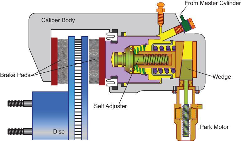
Hydraulic Brakes and Air-Over-Hydraulic Brake Systems
 Hydraulic Brakes and Air-Over-Hydraulic Brake Systems Objectives Describe the principles of operation of a hydraulic brake system. Identify the major components in a truck hydraulic brake system. Describe
FRONT GENERAL A X L E
 GENERAL General diagram of braking circuits 30 FRONT AXLE GENERAL Tightening torques (in dan.m) 30 FRONT AXLE GENERAL Tightening torques (in dan.m) 30 REAR AXLE GENERAL Tightening torques (in dan.m) 30
AUTOMOTIVE SPECIALIZATION (Brakes) STUDENT GRADE RECORD Career & Technical Education
 STUDENT GRADE RECORD Career & Technical Education") STUDENT GRADE RECORD Career & Technical Education Course Outline Modules Windham Module Test Module Competency Rating WINDHAM SCHOOL DISTRICT 1. CTE Orientation 2. Introduction to Brake Systems 3. Shop
STUDENT GRADE RECORD Career & Technical Education Course Outline Modules Windham Module Test Module Competency Rating WINDHAM SCHOOL DISTRICT 1. CTE Orientation 2. Introduction to Brake Systems 3. Shop
Air Brake Manual. Working with drivers to make our roads safer.
 Air Brake Manual Working with drivers to make our roads safer. Foreword The Air Brake Manual has been prepared by Manitoba Public Insurance, to assist drivers in understanding the basic operation and function
GROUP 35A 35A-1 CONTENTS GENERAL DESCRIPTION... 35A-3 BASIC BRAKE SYSTEM DIAGNOSIS 35A-6 HYDRAULIC BRAKE BOOSTER (HBB) DIAGNOSIS...
 DIAGNOSIS...") 35A-1 GROUP 35A CONTENTS GENERAL DESCRIPTION......... 35A-3 DIAGNOSIS 35A-6 INTRODUCTION..................... 35A-6 DIAGNOSTIC TROUBLESHOOTING STRATEGY......................... 35A-6 SYMPTOM CHART...................
35A-1 GROUP 35A CONTENTS GENERAL DESCRIPTION......... 35A-3 DIAGNOSIS 35A-6 INTRODUCTION..................... 35A-6 DIAGNOSTIC TROUBLESHOOTING STRATEGY......................... 35A-6 SYMPTOM CHART...................
BRAKE VALVES. ZRL3513ZA 1/4 NPT Cable operated Manual Drain Release Valve. Cable Length 1600mm
 R6 Relay Valve RE6 Relay Emergency Valve R8 Relay Valve R12 Relay Valve Z279180 SUP: 3/8 NPT.. CONT: 1/4 NPT. R-6 style relay valve is primarily used on vehicles to apply and release rear Z101197 SUP: