Introduction and Overview to Friction Brakes. Course 105 PREVIEW ONLY PARTICIPANT GUIDE
|
|
|
- Claud Luke Briggs
- 5 years ago
- Views:
Transcription


1 Introduction and Overview to Friction Brakes Course 105 PARTICIPANT GUIDE
2 Table of Contents How to Use the Participant Guide... ii MODULE General Principles and Terminology Safety Review Overview to Friction Brakes Train Brakes Classification Summary...8 MODULE Pneumatic Braking Systems Overview and Principle of Operation Electronic Control Brake Control Air Supply Braking Devices Summary...25 MODULE Hydraulic Braking Systems Overiew and Principle of Operation Electronic Control Brake Control Braking Devices Summary...39 MODULE Electromechanical Brakes Overiew and Principle of Operation Types of Electromechanical Brakes Summary...44 MODULE Foundation Brake Equipment Overiew Major Components Summary...51 MODULE Tools and Materials Overiew General Tools Specialized Tools Summary...57 Table of FiguresPREVIEW ONLY DRAFT Intended For Use by Rail Car Training Consortium Members Only 2017Transportation Learning Center Page iii
3 MODULE 1 Outline COURSE 105: INTRODUCTION AND OVERVIEW TO FRICTION BRAKES MODULE 1: GENERAL PRINCIPLES AND TERMINOLOGY 1-1 Safety Review 1-2 Overview to Friction Brakes 1-3 Train Brakes Classification 1-4 Summary Outcome and Objectives GENERAL PRINCIPLES AND TERMINOLOGY Participants will be able to explain the principles of a rail vehicle s friction brakes. Following the completion of this module, the participant should be able to complete the objectives with an accuracy of 75% or greater: List safety considerations specific to working with friction brakes. Describe a rail vehicle s braking control system Explain the purpose of friction braking Categorize common classifications of friction braking systems Key Terms Blended Service Braking Brake Control System Dynamic Braking Friction Braking Standard Operating Procedure (SOP) Abbreviations ANSI: American National Standards Institute BCU: Brake Control Unit ECU: Electronic Control Unit HCU: Hydraulic Control Unit (sometimes HPCU for Hydraulic Pressure Control Unit LOTO: Lockout/Tagout OEM: Original Equipment Manufacturer OSHA Occupational Safety and Health Administration PPE: Personal Protective Equipment PSI: Pounds per Square Inch Transportation Learning Center Page 1

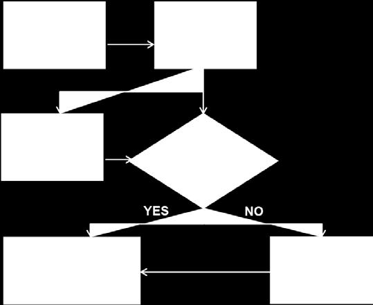
4 COURSE 105: INTRODUCTION AND OVERVIEW TO FRICTION BRAKES MODULE 1: GENERAL PRINCIPLES AND TERMINOLOGY demand for braking occurs than can be supplied by dynamic braking then then friction braking is applied. Figure 1.4 presents an overview to the sequencing of dynamic and friction braking. Figure 1.5 Train Braking Sequence Chart The friction brake system on a rail vehicle is a complex system actuated by a pressure system (pneumatic or hydraulic) along with electromechanical and spring-applied systems. Many rail cars use three types of braking: dynamic, friction, and electromechanical. Dynamic braking is the use of the electric traction motors, which act as generators when decelerating or slowing down the train. The motion of the wheels causes the motors to rotate, which generates electrical energy. It is the traction motors that convert the energy into an electrical current. In the final phase of deceleration, dynamic braking fades out and friction braking begins to take over progressively and proportionally to decelerate the rail car. The combination of dynamic and friction braking is known as blended service braking and its purpose is to ensure a smooth and even deceleration rate. Friction braking is a common braking system used by trains and it acts by dissipating the kinetic energy of the moving train and converting the energy to heat. The heat is generated from the friction between the brake pad and the brake disc or between block and wheel tire during braking. Friction braking is the most common type of brake used by trains, it acts by dissipating the kinetic energy of the moving train by converting the energy into heat. There is an entire course in this series devoted to friction brakes. Transportation Learning Center Page 6
5 MODULE 2 Outline COURSE 105: INTRODUCTION AND OVERVIEW TO FRICTION BRAKES MODULE 2: PNEUMATIC BRAKING SYSTEMS 2-1 Overview and Principle of Operation 2-2 Electronic Control 2-3 Brake Control 2-4 Air Supply 2-5 Braking Devices 2-6 Summary Outcome and Objectives Pneumatic Braking Systems Participants will be able to explain the principles of pneumatic brakes and their components on rail cars used in major U.S. transportation agencies. Following the completion of this module, the participant should be able to complete the objectives with an accuracy of 75% or greater: Explain the principles of operation of a pneumatic brake system Identify the major components of the foundation subsystems of a pneumatic brake system: Electronic control, brake control, air supply, and braking devices. Following the completion of this module, the participant should be able to complete the objectives with an accuracy of 75% or greater: Key Terms Added weight (AW) Fail safe Air supply unit Flat spots (wheel flats) Brake control unit J-1 valve Braking devices Load weigh valve Check valves P-signal Control valves Relay valve Control volume Slip/slide/creep control Dump valve Test ports (test fittings) Electronic control module Variable load valve Electronic control unit Wheel creep Emergency brake (EB) valve Wheel slide Emergency magnet valve Wheel slip Transportation Learning Center Page 9
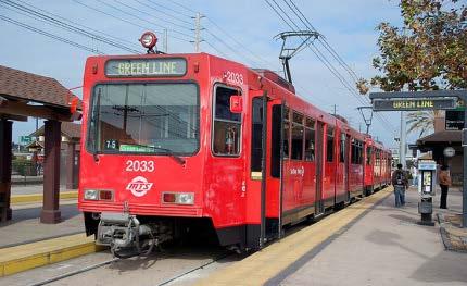
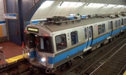
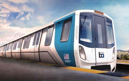
6 COURSE 105: INTRODUCTION AND OVERVIEW TO FRICTION BRAKES MODULE 2: PNEUMATIC BRAKING SYSTEMS 2-1 OVERVIEW AND PRINCIPLE OF OPERATION Pneumatic describes any equipment that is operated by or with air pressure. This is why pneumatic brakes are sometimes referred to as air brakes. A pneumatic brake system is a power braking system with compressed air as the operating medium. In the pneumatic friction braking system, high pressure air is used to create the friction forces necessary to slow or stop the rail vehicle. In a broad sense, a rail vehicle s pneumatic brake system operates in a similar fashion like the brakes on your car. When you press the brake foot pedal in your car, pressure is transferred through brake fluid to a set of pistons which, in turn, clamps a pair of brake pads over the brake discs in the car s wheel. Instead of brake fluid, a rail vehicle uses pressurized air stored in a reservoir. The pneumatic braking system begins with an air compressor which supplies the reservoir which holds the compressed air ready for use. The reservoir supplies the train operator s controls and the train operator controls when to apply or release the brakes. In this module the description of the operating principle of a rail pneumatic braking system is deliberately broad in its scope. The goal here is to introduce the participant to general principles which will open discussion during class and for the instructor and participants to compare and contrast these broad principles with the specific operation of the rail vehicles on which they will work. Additionally the illustrations of components are gathered from various types of rail vehicles courtesy of the Rail Car Training Consortium member agencies and so do not represent one specific vehicle. Figure 2.1 represents the relationship among the four functional areas of the pneumatic brake which are: Electronic Control Brake Control Air Supply Braking Devices The train operator uses the master controller to request braking effort. The request is processed by the electronic control unit (ECU) which interprets the requested braking effort and signals the brake control unit (BCU) to respond accordingly by activating various braking devices. Within the BCU are control valves that are supplied with compressed air stored by the air supply unit and provided by an air compressor. Transportation Learning Center Page 10


7 COURSE 105: INTRODUCTION AND OVERVIEW TO FRICTION BRAKES MODULE 2: PNEUMATIC BRAKING SYSTEMS Figure 2.1 Pneumatic Braking System Functional Areas For the rest of this module, we will build on these four foundation systems examining their components and the roles they play in the overall friction braking system. 2-2 ELECTRONIC CONTROL The control center for the rail vehicle s braking system is governed by the electronic control unit 1 (ECU). This is a logic controller that monitors many functions of the rail vehicle including those which provide friction brake service and wheel-slide control. On newer rail cars, the ECU is a microprocessor-based device with extensive fault detection and annunciation capabilities to which portable test equipment (PTE) can be connected to report specific faults. For this course we will focus on the basic monitoring functions of the ECU some of which are represented in Figure 2.2. The location of the ECU varies by rail vehicle type and design. The ECU takes in external signals from the vehicle, buffers these signals, and then uses them to provide a calculation of the required braking effort, which is output as a controlled volume pressure to control the brake cylinder pressure. 1 On some rail car configurations the ECU is referred to as an electronic control module (ECM) and on others this is referred to as the electronic controlled pneumatic (ECP) equipment. Transportation Learning Center Page 11

8 COURSE 105: INTRODUCTION AND OVERVIEW TO FRICTION BRAKES MODULE 2: PNEUMATIC BRAKING SYSTEMS Learning Application 2.3 Variable Load Valve Your instructor will hand you a two-page printout from PATCO s Running Maintenance and Service Manual describing a variable load valve and how it works in the brake control system on their rail cars. 1. Working with a partner, highlight the flow of air into port 8A and out to cavity 4A on the diagram on the handout. 2. Complete this sentence from the manual: The VLV provides a proportional in braking effort as pressure increases. The amount of braking effort, relative to air spring pressure increase, is a function of the of the lower spring plus the ratio of the areas of the and step piston surfaces. 3. Through what does air under pressure flow into chamber A from chamber C? 4. Though what does supply pressure flow into chamber D? 5. What happens when the force of air in chamber A exceeds the force of the air spring pressure in chamber B? 6. Under what conditions does zero air spring pressure occur? 7. What is the only force operating against the force of the pressurized air in chamber A? What is the result of this situation? 8. Which component cuts off further flow of SR air into chambers A and 4A? What happens then? Transportation Learning Center Page 21

9 COURSE 105: INTRODUCTION AND OVERVIEW TO FRICTION BRAKES MODULE 2: PNEUMATIC BRAKING SYSTEMS Figure 2.11 Air Compressor Unit on HRV courtesy Maryland MTA Figure 2.12 Air Compressor Unit with Air Dryer Unit courtesy PATCO Overpressure safety valves are used between certain stages and will vent the air to atmosphere if the system s normal operating parameters are exceeded. They are installed for safety purposes. A pressure switch which monitors the reservoir s air pressure is used to turn the compressor on when the air tank s lower pressure set point is reached, and off when the air tank s upper pressure set point is achieved. By doing this, adequate air pressure can be maintained for the braking system s use. Transportation Learning Center Page 24
10 MODULE 3 Outline COURSE 105: INTRODUCTION AND OVERVIEW TO FRICTION BRAKES MODULE 3: HYDARULIC BRAKING SYSTEMS 3-1 Overview and Principle of Operation 3-2 Electronic Control 3-3 Brake Control 3-4 Braking Devices 3-5 Summary Outcome and Objectives Hydraulic Braking Systems Participants will be able to explain the principles of hydraulic braking and their components on rail cars used in major U.S. transportation agencies. Following the completion of this module, the participant should be able to complete the objectives with an accuracy of 75% or greater: Explain the principles of operation of a hydraulic brake system. Identify the major components of the foundation subsystems of a hydraulic brake system: Electronic control, brake control, and braking devices. Following the completion of this module, the participant should be able to complete the objectives with an accuracy of 75% or greater: Key Terms Accumulator Load weigh valve Actuator P-signal Brake control unit Slip/slide/creep control Braking devices Suspension legs (struts) Electro Hydraulic Unit (EHU) Variable load valve Electronic control unit Wheel creep Fail safe Wheel slide Flat spots (wheel flats) Wheel slip Transportation Learning Center Page 26
. This is a logic controller that monitors many functions of the rail vehicle including those which provide friction brake service and wheel-slide control.")

11 COURSE 105: INTRODUCTION AND OVERVIEW TO FRICTION BRAKES MODULE 3: HYDARULIC BRAKING SYSTEMS 3-2 ELECTRONIC CONTROL The control center for the rail vehicle s braking system is governed by the electronic control unit 2 (ECU). This is a logic controller that monitors many functions of the rail vehicle including those which provide friction brake service and wheel-slide control. On newer rail cars, the ECU is a microprocessor-based device with extensive fault detection and annunciation capabilities to which portable test equipment (PTE) can be connected to report specific faults. For this course we will focus on the basic monitoring functions of the ECU some of which are represented in Figure 3.2. The location of the ECU varies by rail vehicle type and design. The ECU takes in external signals from the vehicle, buffers these signals, and then uses them to provide a calculation of the required braking effort, which is output as a controlled volume pressure to control the brake cylinder pressure. It is easy to see why the ECU is typically described as the brains of the hydraulic braking system. Along with the request from the Master Controller, the ECU processes other inputs including load weigh pressure, emergency brake request, dynamic brake feedback, automatic train protection, and other inputs. While in-depth examination of the ECU is outside the scope of this course, the participant should be able to describe those functions of the ECU which directly relate to friction brakes. These are also shown in Figure 3.2. Figure 3.2 ECU Functionality 2 On some rail car configurations the ECU is referred to as an electronic control module (ECM). Transportation Learning Center Page 29


12 COURSE 105: INTRODUCTION AND OVERVIEW TO FRICTION BRAKES MODULE 3: HYDARULIC BRAKING SYSTEMS Accumulator Pressurized hydraulic fluid is stored in accumulators. Liquids for the purpose of hydraulic actuation are incompressible and they need to be pressurized through some external source. This external source can be a spring, a raised weight, or more commonly, compressed gas. Gasses are highly compressible. In many rail vehicle hydraulic braking systems, the accumulators use a flexible diaphragm with fluid on one side and pressurized gas on the other side. Nitrogen is commonly used as the pressurized gas. The function of the accumulator is to provide high capacity flow rate as for braking. It also provides reserve pressure source in the event of a hydraulic pump failure. Figure 3.8 Brake Accumulator courtesy CATS Transportation Learning Center Page 38
13 MODULE 4 Outline COURSE 105: INTRODUCTION AND OVERVIEW TO FRICTION BRAKES MODULE 3: ELECTROMECHANICAL BRAKES 4-1 Overview and Principle of Operation 4-2 Types of Electromechanical Brakes 4-3 Summary Outcome and Objectives Electromechanical Brakes Participants will be able to explain of the principles of electromechanical brakes and their major components on rail cars used in major U.S. transportation agencies. Following the completion of this module, the participant should be able to complete the objectives with an accuracy of 75% or greater: Explain the principles of operation of an electromechanical brake system Identify the types of electromechanical brakes and their major components. Following the completion of this module, the participant should be able to complete the objectives with an accuracy of 75% or greater: Key Terms Eddy Currents Electromagnetic Brakes (EM) Electromechanical Transportation Learning Center Page 40


14 COURSE 105: INTRODUCTION AND OVERVIEW TO FRICTION BRAKES MODULE 3: ELECTROMECHANICAL BRAKES The EM brake on the rail vehicle is connected to batteries that create alternating north and south poles which form magnetic fields between the poles. The magnetic fields generate eddy currents in the top surface of the rails, creating a force acting in an opposite direction to the movement of the train, in other words, a braking force. This principle of operation of electromagnetic brakes on a rail car is illustrated in Figure 4.1. Figure 4.1 Electromagnetic Rail Braking Force and Eddy Currents Source One type of electromagnetic brake which is common on light rail vehicles is the track brake (see Figure 4.2). Figure 4.2 Track Brake on LRV courtesy DenverRTD Transportation Learning Center Page 43
15 MODULE 5 Outline 5-1 Overview COURSE 105: INTRODUCTION AND OVERVIEW TO FRICTION BRAKES MODULE 3: HYDARULIC BRAKING SYSTEMS 5-2 Major Components 5-3 Summary Outcome and Objectives Foundation Brake Equipment Participants will be able to explain the foundation brake equipment common to various types of braking systems on passenger rail vehicles in the U.S. Following the completion of this module, the participant should be able to complete the objectives with an accuracy of 75% or greater: Identify major components that comprise the foundation brake equipment of friction braking systems. Describe the functions of the foundation brake equipment Key Terms Brake Calipers Brake Head Disc Brake Rotor (Friction Ring, Brake Disc) Shoes Tread Brake Unit Transportation Learning Center Page 45

16 COURSE 105: INTRODUCTION AND OVERVIEW TO FRICTION BRAKES MODULE 3: HYDARULIC BRAKING SYSTEMS 5-2 MAJOR COMPONENTS The major foundation braking equipment located around the train wheel includes the calipers, brake pads or shoes, the brake disc or rotor, and shunt. Figure 5.1 Brake Components Located Near the Wheel Brake Pads / Shoes The brake pad or shoe is a replaceable friction element that is secured to a brake head for the purpose of producing a retarding friction force on to the face of a brake disc. Transportation Learning Center Page 47
17 MODULE 6 Outline 6-1 Overview 6-2 General Tools COURSE 105: INTRODUCTION AND OVERVIEW TO FRICTION BRAKES MODULE 6: TOOLS 6-3 Specialized Tools 6-4 Summary Outcome and Objectives Tools and Materials Participants will be able to explain the tools and materials the technician may use while working on the rail vehicle s friction brake systems. Following the completion of this module, the participant should be able to complete the objectives with an accuracy of 75% or greater: Identify tools and supplies specific to working on a rail vehicle s friction brake system. Transportation Learning Center Page 52

18 6-1 OVERIEW COURSE 105: INTRODUCTION AND OVERVIEW TO FRICTION BRAKES MODULE 6: TOOLS It is almost impossible to list all the tools a rail car technician must use while performing work on the friction brakes system on the rail car! This module presents some of the common tools, equipment, and materials used across the Consortium s rail transit agencies. Of course these tools and equipment vary by agency with respect to their configuration, layout, availability, and design. Generally the OEM manuals list required tools and materials need for inspection, maintenance, and repair of friction brakes systems. A good example is shown in Figure 6.1. Figure 6.1 Required tools and materials from heavy repair manual courtesy of NFTA Where applicable, illustrations in this module are specific to the equipment used by the rail transportation agency cited below each illustration. Transportation Learning Center Page 53
Inspection and Maintenance of Friction Brakes. Course 205 PREVIEW ONLY PARTICIPANT GUIDE
 Inspection and Maintenance of Friction Brakes Course 205 PARTICIPANT GUIDE Friction Brakes Inspection and Maintenance Course 205 Participant Guide November 2017 DRAFT Rail Car Training Consortium Table
Introduction and Overview to Propulsion and Dynamic Braking Systems PREVIEW ONLY. Course 103 PARTICIPANT GUIDE
 Introduction and Overview to Propulsion and Dynamic Braking Systems Course 103 PARTICIPANT GUIDE Table of Contents How to Use the Participant Guide... ii MODULE 1 General Principles and Terminology...1
Chapter 33 Fundamentals of Hydraulic and Air-Over-Hydraulic Braking Systems
 Chapter 33 Fundamentals of Hydraulic and Air-Over-Hydraulic Braking Systems Introduction Vehicle s braking system must meet the following requirements: To adequately and safely reduce a vehicle s speed,
Module 11: Antilock Brakes Systems
 ÂÂ ABS Brake System Antilock Brake System Operation Principles of ABS Braking ABS Master Cylinder Hydraulic Control Unit Wheel Speed Sensors ABS Electronic Control Unit Terms and Definitions Purposes for
PREVIEW ONLY - FULL COPY AVAILABLE TO CONSORTIUM MEMBERS. Escalator Specific Electrical Systems. Course 209 PARTICIPANT GUIDE
 Escalator Specific Electrical Systems Course 209 PARTICIPANT GUIDE Transit Elevator/Escalator Training Consortium Escalator: Electrical Systems Participant Guide Transit Elevator/Escalator Maintenance
For Signals Training Consortium Use Only
 Introduction and Overview to Switches and Derails Course 102 PARTICIPANT GUIDE Page Intentionally Left Blank Cover Photo Courtesy NFTA Introduction and Overview to Switches and Derails Participant Guide
PREVOST AIR SYSTEMS WHAT THEY DO AND HOW THEY DO IT
 PREVOST AIR SYSTEMS WHAT THEY DO AND HOW THEY DO IT Air. In our buses we use air for many purposes. We warm ourselves and cool ourselves with it. We supply it to our engines so they will run. Air is what
Inspection and Basic Maintenance of Brake Systems
 Inspection and Basic Maintenance of Brake Systems 11-1 Types Air brakes Hydraulic brakes Secondary braking systems 11-2 Air Brake System Most large, modern fire apparatus are equipped with air-operated
FLUID POWER FLUID POWER EQUIPMENT TUTORIAL PNEUMATIC CIRCUTS. This work covers part of outcome 3 of the Edexcel standard module:
 FLUID POWER FLUID POWER EQUIPMENT TUTORIAL PNEUMATIC CIRCUTS This work covers part of outcome 3 of the Edexcel standard module: UNIT 21746P APPLIED PNEUMATICS AND HYDRAULICS The material needed for outcome
COASTAL BEND COLLEGE AUTOMOTIVE TECHNOLOGY SYLLABUS (rev. Fall 2012)
") COASTAL BEND COLLEGE AUTOMOTIVE TECHNOLOGY SYLLABUS (rev. Fall 2012) AUMT 1310: Automotive Brake Systems SEMESTER HOURS: 3 TEXTBOOK Automotive Technology A systems Approach COURSE DESCRIPTION; Operation
COASTAL BEND COLLEGE AUTOMOTIVE TECHNOLOGY SYLLABUS (rev. Fall 2012) AUMT 1310: Automotive Brake Systems SEMESTER HOURS: 3 TEXTBOOK Automotive Technology A systems Approach COURSE DESCRIPTION; Operation
BRAKE SYSTEM DESIGN AND THEORY
 RAKE SYSTEM DESIGN AND THEORY Aircraft brake systems perform multiple functions. They must be able to hold the aircraft back at full static engine run-up, provide adequate control during ground taxi operations,
TECHNICAL PAPER 1002 FT. WORTH, TEXAS REPORT X ORDER
 I. REFERENCE: 1 30 [1] Snow Engineering Co. Drawing 80504 Sheet 21, Hydraulic Schematic [2] Snow Engineering Co. Drawing 60445, Sheet 21 Control Logic Flow Chart [3] Snow Engineering Co. Drawing 80577,
Modern Auto Tech Study Guide Chapters 71 & 73 Pages Brake Systems 49 Points. Automotive Service
 Modern Auto Tech Study Guide Chapters 71 & 73 Pages 1369 1444 Brake Systems 49 Points 1. Automotive systems use to stop, slow or to hold the wheels from turning. Brake, Friction Brake, Fraction Brake,
PREVIEW ONLY. Course 106 INSTRUCTOR GUIDE. HVAC Systems Introduction and Overview. Module 1: Overview of Rail Car HVAC and General Safety Procedures
 Course 106 HVAC Systems Introduction and Overview Module 1: Overview of Rail Car HVAC and General Safety Procedures INSTRUCTOR GUIDE Table of Contents CHECKLIST FOR INSTRUCTION... 3 SUPPLIES, AUDIO-VISUAL
4.4. Forces Applied to Automotive Technology. The Physics of Car Tires
 Forces Applied to Automotive Technology Throughout this unit we have addressed automotive safety features such as seat belts and headrests. In this section, you will learn how forces apply to other safety
FUNDAMENTAL PRINCIPLES
 FUNDAMENTAL PRINCIPLES Fundamental Principles The most important safety feature of an automobile is its brake system. The ability of a braking system to provide safe, repeatable stopping is the key to
C. Brake pads Replaceable friction surfaces that are forced against the rotor by the caliper piston.
 BRAKES UNIT 1: INTRODUCTION TO BRAKE SYSTEMS LESSON 1: FUNDAMENTAL PRINCIPLES OF BRAKE SYSTEMS I. Terms and definitions A. Brake fading Loss of brakes, usually due to heat. B. Brake lining Material mounted
How Regenerative Braking Works
 Feature How Regenerative Braking Works The regenerative braking systems on Nissan hybrid vehicles can be confusing and misunderstood. Let s take a look at how these systems really work. 26 Nissan TechNews
ANTI-LOCK BRAKES. Section 9. Fundamental ABS Systems. ABS System Diagram
 ANTI-LOCK BRAKES Fundamental ABS Systems Toyota Antilock Brake Systems (ABS) are integrated with the conventional braking system. They use a computer controlled actuator unit, between the brake master
1. INTRODUCTION. Anti-lock Braking System
 1. INTRODUCTION Car manufacturers world wide are vying with each other to invent more reliable gadgets there by coming closer to the dream of the Advanced safety vehicle or Ultimate safety vehicle, on
Brake Systems. Introduction
 Brake Systems Figure 1. A Typical Brake System Introduction The brake system (Figure 1) is designed to slow and halt the motion of a vehicle. To do that, various components within a hydraulic brake system
DISCUSSION OF FUNDAMENTALS. A hydraulic system can be controlled either manually or automatically:
 Unit 1 Introduction to Electrical Control of Hydraulic Systems UNIT OBJECTIVE When you have completed this unit, you will be able to identify the components used for electrical control of the Hydraulics
Module 6: Air Foundation Brakes
 Air Brakes Terms and Definitions Basic Components That Make Up Air Foundation Brakes Types of Air Foundation Brakes Parts of a Cam Foundation Brake Parts of a Wedge Foundation Brake Parts of a Disc Foundation
MECA0063 : Braking systems
 MECA0063 : Braking systems Pierre Duysinx Research Center in Sustainable Automotive Technologies of University of Liege Academic Year 2018-2019 1 Bibliography T. Gillespie. «Fundamentals of vehicle Dynamics»,
ABS keeps the vehicle steerable, even during an emergency braking
 ABS keeps the vehicle steerable, even during an emergency braking under all road conditions 1 Contents! Safety systems in vehicles! Why do you need ABS?! How does ABS work?! What are the benefits of ABS?!
Assignment 3 Hydraulic Brake Systems
 Name(s) Assign_3_Hydraulics Assignment 3 Hydraulic Brake Systems BE SURE TO SAVE THIS FILE before, during and after completing your work. (Hint if you write your name, then save and close this, your name
Focus Area Level Report Including Knowledge and Skills, and Performance Indicators
 Including Knowledge and Skills, and PST 01. Use physical science principles and engineering applications with power, structural and technical systems to solve problems and improve performance. PST 01.01.
Unit HV04K Knowledge of Heavy Vehicle Chassis Units and Components
 Assessment Requirements Unit HV04K Knowledge of Heavy Vehicle Chassis Units and Components Content: Chassis layouts i. types of chassis ii. axle configurations iii. rear steered axles iv. self-steered
Marine and Outdoor Power Equipment Technician Level 2
 Level 2 Unit: B2 Trade Mathematics II Level: Two Duration: 16 hours Theory: Practical: 16 hours 0 hours Overview: This unit is designed to provide the apprentice with the knowledge and ability to apply
UNIT I CLASSIFICATION AND REQUIREMENTS OF OFF ROAD VEHICLES
 UNIT I CLASSIFICATION AND REQUIREMENTS OF OFF ROAD VEHICLES INTRODUCTION It is a common fact that we find a wide variety of construction machines on every construction sites, which make the construction
UNDERGROUND MINING. Mine hoist disc brake systems Improved safety, availability and productivity
 UNDERGROUND MINING Mine hoist disc brake systems Improved safety, availability and productivity 2 MINE HOIST DISC BRAKE SYSTEMS IMPROVED SAFETY, AVAILABILITY AND PRODUCTIVITY Mine hoist disc brake systems
SAULT COLLEGE OF APPLIED ARTS AND TECHNOLOGY SAULT STE. MARIE, ONTARIO COURSE OUTLINE CODE NO. : MPT 230 SEMESTER: 4
 SAULT COLLEGE OF APPLIED ARTS AND TECHNOLOGY SAULT STE. MARIE, ONTARIO COURSE OUTLINE COURSE TITLE: Air Brakes CODE NO. : MPT 230 SEMESTER: 4 PROGRAM: AUTHOR: Motive Power Technician Advanced Repair George
White Paper: The Physics of Braking Systems
 White Paper: The Physics of Braking Systems The Conservation of Energy The braking system exists to convert the energy of a vehicle in motion into thermal energy, more commonly referred to as heat. From
Applications of Pneumatics and Hydraulics
 Unit 24: Applications of Pneumatics and Hydraulics Unit code: J/601/1496 QCF level: 4 Credit value: 15 Aim This unit aims to extend learners understanding of pneumatic and hydraulic fluid power systems
Day 5 Practical and Written Final SAE Exams for SAE Int l Advanced HEV Diagnostics CoC
 One of the fastest growing automotive sectors is the field of vehicles using electric propulsion systems. These technologies are providing significant opportunities and challenges to automotive instructors
BRAKE SYSTEM FUNDAMENTALS KARAN BHARDIYA ASSISTANT MANAGER -R&D ENDURANCE TECHNOLOGIES PVT.LTD. DISC BRAKES
 BRAKE SYSTEM FUNDAMENTALS KARAN BHARDIYA ASSISTANT MANAGER -R&D ENDURANCE TECHNOLOGIES PVT.LTD. DISC BRAKES AUTOMOTIVE BRAKING SYSTEMS How brakes manufacturing industry is different then rest of the automotive
Engineering Diploma Resource Guide ST280 ETP Hydraulics (Engineering)
") Engineering Diploma Resource Guide ST80 ETP Hydraulics (Engineering) Introduction Hydraulic systems are a fundamental aspect of engineering. Utilised across a variety of sectors including aviation, construction,
Engineering Diploma Resource Guide ST80 ETP Hydraulics (Engineering) Introduction Hydraulic systems are a fundamental aspect of engineering. Utilised across a variety of sectors including aviation, construction,
MASTER CYLINDER. Section 2. Lesson Objectives
 MASTER CYLINDER Lesson Objectives 1. Explain the difference between conventional and diagonal split piping system and their application. 2. Describe the function of the compensating port of the master
MOTOR TERMINAL CONNECTIONS
 MOTOR TERMINAL CONNECTIONS Motor Classification Most of the industrial machines in use today are driven by electric motors Motors are classified according to the type of power used (AC or DC) and the motors
Jogging and Plugging of AC and DC Motors. Prepared by Engr. John Paul Timola, LPT
 Jogging and Plugging of AC and DC Motors Prepared by Engr. John Paul Timola, LPT Jogging sometimes called inching momentary operation of a motor for the purpose of accomplishing small movements of the
REV F2.0. User's Manual. Hydraulic ABS (HABS) Hydraulic Power Brake (HPB) Page 1 of 28
 Hydraulic Power Brake (HPB) Page 1 of 28") REV F2.0 User's Manual Hydraulic ABS (HABS) Hydraulic Power Brake (HPB) Page 1 of 28 Table of Contents INTRODUCTION...4 Starting TOOLBOX Software... 5 MAIN MENU...6 System Setup... 6 Language... 7 Select
REV F2.0 User's Manual Hydraulic ABS (HABS) Hydraulic Power Brake (HPB) Page 1 of 28 Table of Contents INTRODUCTION...4 Starting TOOLBOX Software... 5 MAIN MENU...6 System Setup... 6 Language... 7 Select
1 of 9 7/19/2016 5:35 PM
 1 of 9 7/19/2016 5:35 PM PADS - FRONT/REAR BRAKE - SRT8 STANDARD PROCEDURE BRAKE PAD BURNISHING CAUTION: After installing NEW brake pads, keep in mind that braking effectiveness might be somewhat reduced
2017 National HDT Rally
 2017 National HDT Rally Importance of Trailer Brakes When te DOT certifies a GCWR, the assumption is that the towed vehicle is supplying it own stopping power. A Class 8 truck is generally considered a
IAE-101: Electrical Fundamentals for Non-Electrical Personnel
 IAE-101: Electrical Fundamentals for Non-Electrical Personnel Abstract Today s world of rapidly evolving technology poses a wealth of challenges just to remain competitive in the marketplace. Everyone
LEVEL 1/2 CAMBRIDGE NATIONAL AWARD/CERTIFICATE IN PRINCIPLES IN ENGINEERING AND ENGINEERING BUSINESS. Candidate Surname
 SPECIMEN LEVEL 1/2 CAMBRIDGE NATIONAL AWARD/CERTIFICATE IN PRINCIPLES IN ENGINEERING AND ENGINEERING BUSINESS R101: Engineering Principles Candidates answer on the Question Paper OCR Supplied Materials:
DESCRIPTION & OPERATION
 DESCRIPTION & OPERATION BRAKE BOOSTER Delco-Moraine Single Diaphragm A combined vacuum-hydraulic unit which uses a combination of intake manifold vacuum and atmospheric pressure to provide power assist.
EB : e-stroke GEN 3 USERS GUIDE for Bus Applications
 EB 09-005: e-stroke GEN 3 USERS GUIDE for Bus Applications SECTION 1: INTRODUCTION The purpose of the e-stroke Brake Monitoring System is to enhance the operational safety of commercial vehicles. The e-stroke
Instructor Training Manual. Chapter 6 HYDRAULICS & PNEUMATICS
 Instructor Training Manual Chapter 6 HYDRAULICS & PNEUMATICS Learning Objectives 1. The purpose of this chapter is to provide a basic introduction to the principles of hydraulics & pneumatics and their
Braking System Layout
 The Braking System The energy used to accelerate or move a vehicle from rest to a certain speed is called Kinetic i (moving) energy. To slow the vehicle down, this kinetic energy must be converted or changed,
I) Clamping the work piece II) Drilling the work piece. III) Unclamping the work piece. 10
 Clamping the work piece II) Drilling the work piece. III) Unclamping the work piece. 10") Seventh Semester B.E. III IA Test, 2014 USN 1 P E M E PES INSTITUTE OF TECHNOLOGY (Bangalore South Campus) (Hosur Road, 1KM before Electronic City, Bangalore-560 100) Department of Mechanical Engineering
Seventh Semester B.E. III IA Test, 2014 USN 1 P E M E PES INSTITUTE OF TECHNOLOGY (Bangalore South Campus) (Hosur Road, 1KM before Electronic City, Bangalore-560 100) Department of Mechanical Engineering
Brake System Fundamentals Chapter 71 Name Date Period
 Brake System Fundamentals Chapter 71 Name Date Period Basic Brake System Matching 1. Metal tubing and rubber hose that transmit pressure to the wheel brake assemblies. 2. Mechanical system for applying
8. Other system and brake theories
 8. Other system and brake theories Objective To understand the limiting valve, proportioning valve, load sensing proportioning valve and brake theories, which were used immediately before the development
EE6351 ELECTRIC DRIVES AND CONTROL UNIT-1 INTRODUTION
 EE6351 ELECTRIC DRIVES AND CONTROL UNIT-1 INTRODUTION 1. What is meant by drive and electric drive? Machines employed for motion control are called drives and may employ any one of the prime movers for
C ap a ter 4 Fluid i d P o P w o e w r St S an a d n a d rd a d n d Sy S m m ol o s L n a gua u g a e e o f o t he h e I ndus u t s ry
 Chapter 4 Fluid Power Standards and Symbols Language of the Industry 1 Objectives Describe the meaning of a standard and the importance of standardization in an industry. Identify the primary groups that
To study about various types of braking system.
 To study about various types of braking system INTRODUCTION The system is purely mechanical means & is independent of the hydraulic system which controls the brake normally. A brake commonly referred to
DESIGN, ANALYSIS AND FABRICATION OF BRAKING SYSTEM WITH REAR INBOARD BRAKES IN BAJA ATV
 DESIGN, ANALYSIS AND FABRICATION OF BRAKING SYSTEM WITH REAR INBOARD BRAKES IN BAJA ATV Aman Sharma 1, Prakhar Amrute 2, Suryakant Singh Thakur 3, Jatin Shrivastav 4 1,2,3,4Department of Mechanical Engineering,
Variable Valve Timing
 Service. Self-study programme 246 Variable Valve Timing with fluted variator Design and Function The demands on combustion engines continue to grow. On one hand, customers want more power and torque, while
Brake System Operation
 Brake System Brake System Operation Donald Jones Brookhaven College Master cylinder Brake lines Hydraulic valves Disc brakes Drum brakes Power assist unit Parking brake Antilock system Brake System Functions
Design and Modeling of Fluid Power Systems ME 597/ABE 591
 Systems ME 597/ABE 591 Dr. Monika Ivantysynova MAHA Professor Flud Power Systems MAHA Fluid Power Research Center Purdue University Systems Dr. Monika Ivantysynova, Maha Professor Fluid Power Systems Mivantys@purdue.edu
Overview. KNOTT brakes overview The basics for around 2000 solutions BRAKES. We make your brake
 Overview BRAKES KNOTT brakes overview The basics for around 2000 solutions www.knott.de We make your brake KNOTT develops and produces individual brake solutions for all branches: from agriculture and
CDI Revision Notes Term 1 ( ) Grade 12 Advanced Unit 2 Mechanical Systems
 Grade 12 Advanced Unit 2 Mechanical Systems") CDI Revision Notes Term 1 (2017 2018) Grade 12 Advanced Unit 2 Mechanical Systems STUDENT INSTRUCTIONS Student must attempt all questions. For this examination, you must have: (a) An ink pen blue. (b)
CDI Revision Notes Term 1 (2017 2018) Grade 12 Advanced Unit 2 Mechanical Systems STUDENT INSTRUCTIONS Student must attempt all questions. For this examination, you must have: (a) An ink pen blue. (b)
ABS, 4-ETS and EBP BRAKES ANTI-LOCK BRAKE SYSTEM (ABS) 4-WHEEL ELECTRONIC TRACTION CONTROL SYSTEM (4-ETS) ELECTRONIC BRAKE PROPORTIONING (EBP)
 4-WHEEL ELECTRONIC TRACTION CONTROL SYSTEM (4-ETS) ELECTRONIC BRAKE PROPORTIONING (EBP)") 1 of 9 4/27/2008 7:52 AM Home Account Contact ALLDATA Log Out Help Select Vehicle New TSBs Technician's Reference Component Search: METRO TOYOTA OK 2002 Mercedes Benz Truck ML 320 (163.154) V6-3.2L (112.942)
1 of 9 4/27/2008 7:52 AM Home Account Contact ALLDATA Log Out Help Select Vehicle New TSBs Technician's Reference Component Search: METRO TOYOTA OK 2002 Mercedes Benz Truck ML 320 (163.154) V6-3.2L (112.942)
ATASA 5 th. ABS & Traction Control Systems. Please Read The Summary
 ATASA 5 TH Study Guide Chapter 51 Pages: 1506 1534 Antilock Brake Systems 59 Points Please Read The Summary Before We Begin Keeping in mind the Career Cluster of Transportation, Distribution & Logistics
Test Which component has the highest Energy Density? A. Accumulator. B. Battery. C. Capacitor. D. Spring.
 Test 1 1. Which statement is True? A. Pneumatic systems are more suitable than hydraulic systems to drive powerful machines. B. Mechanical systems transfer energy for longer distances than hydraulic systems.
Instructor Guide. 215: Elevator: Mechanical Drive Systems Module 3: Gearless Drive Systems
 PR EV IE W O N LY Instructor Guide 215: Elevator: Mechanical Drive Systems Module 3: Gearless Drive Systems Table of Contents Overview.......4 Gearless Drive Operation...8 Geared Vs. Gearless. 22 Summary..29
BASIC BRAKE SYSTEM GROUP 35A 35A-1 CONTENTS GENERAL DESCRIPTION... 35A-3 BASIC BRAKE SYSTEM DIAGNOSIS 35A-6
 35A-1 GROUP 35A BASIC BRAKE SYSTEM CONTENTS GENERAL DESCRIPTION......... 35A-3 DIAGNOSIS 35A-6 INTRODUCTION..................... 35A-6 DIAGNOSTIC TROUBLESHOOTING STRATEGY......................... 35A-6
NEW YORK AIR BRAKE CORPORATION
 NEW YORK AIR BRAKE CORPORATION A KNORR BRAKE COMPANY 748 Starbuck Avenue, Watertown, New York 13601 C.W. 307 COMPONENT WRITE-UP OF CCB-26 LOCOMOTIVE BRAKE SYSTEM ISSUE NO. 1 C.W. 307 GENERAL The CCB-26
Automotive Technology II
 Course Title: Course Description: Consists of two primary elements; Starting and Charging Systems covers the operation, testing and servicing of vehicle battery, starting and charging systems. Hybrid/
EFFICIENCY AND POWER 3,000 4,000 LB. CAPACITY ELECTRIC PNEUMATIC TIRE LIFT TRUCKS
 EFFICIENCY AND POWER 3,000 4,000 LB. CAPACITY ELECTRIC PNEUMATIC TIRE LIFT TRUCKS 2 A POWERFUL SOLUTION 3 Maximum Performance: Shift After Shift The Cat EPC3000 EP4000 series is designed for efficiency
A Study of the Two Wheeler Retarder Type Dynamometer System
 A Study of the Two Wheeler Retarder Type Dynamometer System Nilesh R. Mate 1, Prof. D. Y. Dhande 2 P.G. Student, Department of Mechanical Engineering, A.I.S.S.M.S. College of Engineering, Pune, India 1
BRAKE BOOSTER. Section 5. Brake Booster. Construction. Single Diaphragm Booster
 BRAKE BOOSTER Brake Booster The brake booster is designed to create a greater braking force from a minimum pedal effort, using a difference in atmospheric pressure and the engine s manifold vacuum. It
PRESENTATION ON HYDRAULIC BASED COMPONENT
 PRESENTATION ON HYDRAULIC BASED COMPONENT 1.HYDRAULIC CRANE 2.HYDRAULIC LIFT 3.HYDRAULIC ACCUMULATOR 4.HYDRAULIC INTENSIFIER 5.JET PUMP PRESENTED BY: GAURAV SHARMA HYDRAULIC CRANE The hydraulic crane is
Fluid Power Systems: Hydraulics and Pneumatics
 Fluid Power Systems: Hydraulics and Pneumatics Why Attend Fluid power systems (hydraulics and pneumatics) offer an alternate means of controlling industrial systems without a large number of electrical
Ch 4 Motor Control Devices
 Ch 4 Motor Control Devices Part 1 Manually Operated Switches 1. List three examples of primary motor control devices. (P 66) Answer: Motor contactor, starter, and controller or anything that control the
CHAPTER THREE DC MOTOR OVERVIEW AND MATHEMATICAL MODEL
 CHAPTER THREE DC MOTOR OVERVIEW AND MATHEMATICAL MODEL 3.1 Introduction Almost every mechanical movement that we see around us is accomplished by an electric motor. Electric machines are a means of converting
2005 Dodge Grand Caravan
 REMOVAL REMOVAL - REAR DISC BRAKE SHOES 1. Raise vehicle. (Refer to LUBRICATION & MAINTENANCE/HOISTING - STANDARD PROCEDURE). 2. Remove rear wheel and tire assemblies from vehicle. 3. Remove the caliper
Airframes Instructor Training Manual. Chapter 6 UNDERCARRIAGE
 Learning Objectives Airframes Instructor Training Manual Chapter 6 UNDERCARRIAGE 1. The purpose of this chapter is to discuss in more detail the last of the Four Major Components the Undercarriage (or
1. Anti-lock Brake System (ABS)
") W1860BE.book Page 2 Tuesday, January 28, 2003 11:01 PM 1. Anti-lock Brake System () A: FEATURE The 5.3i type used in the Impreza has a hydraulic control unit, an control module, a valve relay and a motor
W1860BE.book Page 2 Tuesday, January 28, 2003 11:01 PM 1. Anti-lock Brake System () A: FEATURE The 5.3i type used in the Impreza has a hydraulic control unit, an control module, a valve relay and a motor
ABS. Prof. R.G. Longoria Spring v. 1. ME 379M/397 Vehicle System Dynamics and Control
 ABS Prof. R.G. Longoria Spring 2002 v. 1 Anti-lock Braking Systems These systems monitor operating conditions and modify the applied braking torque by modulating the brake pressure. The systems try to
LECTURE-23: Basic concept of Hydro-Static Transmission (HST) Systems
 Systems") MODULE-6 : HYDROSTATIC TRANSMISSION SYSTEMS LECTURE-23: Basic concept of Hydro-Static Transmission (HST) Systems 1. INTRODUCTION The need for large power transmissions in tight space and their control
MODULE-6 : HYDROSTATIC TRANSMISSION SYSTEMS LECTURE-23: Basic concept of Hydro-Static Transmission (HST) Systems 1. INTRODUCTION The need for large power transmissions in tight space and their control
2. Draw the speed-torque characteristics of dc shunt motor and series motor. (May2013) (May 2014)
 (May 2014)") UNIT 2 - DRIVE MOTOR CHARACTERISTICS PART A 1. What is meant by mechanical characteristics? A curve is drawn between speed-torque. This characteristic is called mechanical characteristics. 2. Draw the
UNIT 2 - DRIVE MOTOR CHARACTERISTICS PART A 1. What is meant by mechanical characteristics? A curve is drawn between speed-torque. This characteristic is called mechanical characteristics. 2. Draw the
Design Analysis and Optimization of Disc Brake
 Design Analysis and Optimization of Disc Brake Assembly of A 4- Wheeler Race C ar Avijit Singh Gangwar B.E. Automobile Engineer Manipal Institute Of Technology Abstract-A disc brake is a wheel brake which
White paper: Pneumatics or electrics important criteria when choosing technology
 White paper: Pneumatics or electrics important criteria when choosing technology The requirements for modern production plants are becoming increasingly complex. It is therefore essential that the drive
Installing FRK and FRK Hydraulic Compact Unit (HCU) on Navistar Straight Trucks
 on Navistar Straight Trucks") Revised 09-18 Technical Bulletin Installing FRK 09-10091 and FRK 09-10092 Hydraulic Compact Unit (HCU) on Navistar Straight Trucks Revised 1 Technical 09-18 Bulletin Hazard Alert Messages Read and observe
Revised 09-18 Technical Bulletin Installing FRK 09-10091 and FRK 09-10092 Hydraulic Compact Unit (HCU) on Navistar Straight Trucks Revised 1 Technical 09-18 Bulletin Hazard Alert Messages Read and observe
COURSE LEARNING OUTCOMES
 COURSE LEARNING OUTCOMES No. Course Learning Outcome 1. 2. Compare working principle and identify advantages/disadvantages between the disc and drum brake systems used in passenger vehicles Analyze deceleration
Application Note : Comparative Motor Technologies
 Application Note : Comparative Motor Technologies Air Motor and Cylinders Air Actuators use compressed air to move a piston for linear motion or turn a turbine for rotary motion. Responsiveness, speed
 Page 1 of 23 593: Brake control system V70 (00-08), 2004, B5244S2, M56, L.H.D, YV1SW65S241436824, 436824 16/7/2018 PRINT 593: Brake control system ABS control ABS function Active yaw control Active yaw
E-training. Operating characteristics and sizing of pneumatic actuators. The main types of pneumatic actuator
 Welcome to the K Controls e-training course designed to deliver useful Pneumatic Valve Actuation application information in small instalments. To unsubscribe or to register a colleague to receive these
FLUID POWER P&IDs. IDENTIFY the symbols used on engineering fluid power drawings for the following components:
 FLUID POWER P&IDs Fluid power diagrams and schematics require an independent review because they use a unique set of symbols and conventions. EO 1.11 IDENTIFY the symbols used on engineering fluid power
Air Brake Inspection Presented By: G.L. May
 Air Brake Inspection 2012 Presented By: G.L. May Outline of this course Objective of this course: The technician will have a better understanding of requirements for air drum brakes and air disc brakes
Automatic Transmission Basics
 Section 1 Automatic Transmission Basics Lesson Objectives 1. Describe the function of the torque converter. 2. Identify the three major components of the torque converter that contribute to the multiplication
ENRESO.WORLD. Traction Control System. Created by Istas René - enreso.world. Graduated in Autmotomotiv Technolgogys
 ENRESO.WORLD Traction Control System Created by Istas René - enreso.world Graduated in Autmotomotiv Technolgogys Traction Control (TCS) is an option that is often found on vehicles equipped with antilock
Fisher 3660 and 3661 Positioners
 3660 and 3661 Positioners Product Bulletin Fisher 3660 and 3661 Positioners Fisher 3660 pneumatic and 3661 electro pneumatic single acting positioners are used with various actuators on sliding stem valves
BRAKE SYSTEM, HYDRAULICALLY ACTUATED - 631G TRACTOR Cat Tractors with standard shoe/drum brakes
 BRAKE SYSTEM, HYDRAULICALLY ACTUATED - 631G TRACTOR 194139 631 Cat Tractors with standard shoe/drum brakes Kress Corporation modifies the Caterpillar tractor air actuated shoe brake system to a hydraulically
IMILV08 Diagnose and rectify light vehicle chassis system faults
 Overview This NOS is about diagnosing and rectifying faults occurring within vehicle steering, suspension and braking systems. IMILV08 1 Performance criteria You must be able to: P1 wear suitable personal
Job Ready Assessment Blueprint
 Blueprint Test Code: 4209/ Version: 01 Automotive Technician Core Specific Competencies and Skills Tested in this Assessment: Brakes (NATEF A-5) Diagnose and repair hydraulic systems Diagnose and repair
Installation Guide. Installing the FRK Hydraulic Compact Unit (HCU) with Parking Brake Valve on International School Buses
 with Parking Brake Valve on International School Buses") Revised 09-18 Installation Guide Revised 1 Technical 09-18 Bulletin Installing the FRK 08-10086 Hydraulic Compact Unit (HCU) with Parking Brake Valve on International School Buses Hazard Alert Messages
Revised 09-18 Installation Guide Revised 1 Technical 09-18 Bulletin Installing the FRK 08-10086 Hydraulic Compact Unit (HCU) with Parking Brake Valve on International School Buses Hazard Alert Messages
GROUP 35A 35A-1 CONTENTS GENERAL DESCRIPTION... 35A-3 BASIC BRAKE SYSTEM DIAGNOSIS 35A-6 HYDRAULIC BRAKE BOOSTER (HBB) DIAGNOSIS...
 DIAGNOSIS...") 35A-1 GROUP 35A CONTENTS GENERAL DESCRIPTION......... 35A-3 DIAGNOSIS 35A-6 INTRODUCTION..................... 35A-6 DIAGNOSTIC TROUBLESHOOTING STRATEGY......................... 35A-6 SYMPTOM CHART...................
35A-1 GROUP 35A CONTENTS GENERAL DESCRIPTION......... 35A-3 DIAGNOSIS 35A-6 INTRODUCTION..................... 35A-6 DIAGNOSTIC TROUBLESHOOTING STRATEGY......................... 35A-6 SYMPTOM CHART...................
Variable Valve Drive From the Concept to Series Approval
 Variable Valve Drive From the Concept to Series Approval New vehicles are subject to ever more stringent limits in consumption cycles and emissions. At the same time, requirements in terms of engine performance,
ELECTRICAL TECHNOLOGY 3 March 2008
 I. Course Description ELECTRICAL TECHNOLOGY 3 March 2008 The purpose for this course is to instruct potential electricians in the skills necessary for entry into the job market. During this course, the