Service Updates. DMP & Twin Master Combines Section 10. Transmission with Offset Pull Tongue (405036) 2001 to
|
|
|
- Neil Townsend
- 5 years ago
- Views:
Transcription
1 Service Updates DMP & Twin Master Combines Section 10 Transmission with Offset Pull Tongue (405036) 2001 to Transmission with Mounting Kit (405037) 2001 to Transmission Mounting Instructions (510242) 2001 to Transmission with Offset Pull Tongue (405038) 2000 only Transmission with Mounting Kit (405039) 2000 only Transmission Mounting Instructions (510260) 2000 only Shift Lever Kit (405040) Jack Update Kit (405062) Rear Ladder Kit (511212) Elevator Hinged Door Kit (511215) DMP Shaker Arm Update Kit (405059) Return to this page by clicking the upper right corner of any page in this section. Revised January,
2
3 2001 to Present Double Master Plus SERVICE UPDATE KITS 2 Speed Transmission with Offset Pull Tongue Hitch Kit # Parts List Item No. Part No. Qty Description Pull Tongue Hitch (2001 to Present) Pull Tongue Speed Transmission (complete) Transmission Mounting Jig (1-3/4 female receiver) Transmission Mounting Plate Pull Tongue Swivel Pin Hydraulic Hose Carrier Driveline, Primary (1-3/4 20 Spline to 1-3/8 21 Spline) Driveline, Front Secondary (1-3/8 21 Spline to 1-3/4 Overrunning Clutch) Driveline, Rear Secondary (1-3/4 20 Spline to 1-3/4 20 Spline) Splined Shaft Carrier Splined Shaft (1-3/4 20 Spline to 1-3/4 20 Spline) Bearing, 45mm Insert Flange, 45mm (4 hole Round) PTO Swivel Gear Box Front Mounting Plate (Swivel Gear Box) Draw Bar Extension (for use with 1-3/ PTO Tractors) Draw Bar Extension (for use with 1-3/ PTO Tractors) Dura-Ball Hitch Dura-Ball Top Plate Dura-Ball Spacer Stabilizer Mount (2 Speed Transmission) Jack, Sidewinder Dickey-john Cable Extension (not shown) Quick Couplers (not shown) Adapter, Hydraulic ( ) (not shown) Hose, Hydraulic (8M2T-8MP8FP-07200) (not shown) Hose, Hydraulic (6M2T-8MP8MP-24500) (not shown) Cylinder, Hydraulic 3 x 8 (ASAE) Shift Lever Kit (2 Speed Transmission) Sprocket, 60B20 x 1-3/4 (not shown) Sprocket, 60B20 x 2-1/8 (not shown) Chain, 60B20 Coupler (not shown) Shaft, Coupler (1-3/4 O.D. Shaft 2-3/4 Long) (not shown) Stabilizer Mount (PTO Swivel Gear Box) Top Support Plate (2 Speed Transmission) Bottom Support Plate (2 Speed Transmission) Mounting Instructions (2 Speed Transmission / 2001-Present) Hardware List Item No. Part No. Qty Description A /2 x 6-1/2 NC Hex Bolt (with Lockwasher & Nut) B x 9 NC Hex Bolt (with Lockwasher & Nut) C /4 x 9 NC Hex Bolt (with Lockwashers & Nuts) D /4 x 5-1/2 NC Hex Bolt (with Lockwashers & Nuts) E Connection Link 60-2 F. 1 3/8 Keystock (2-3/4 Long) G. 1 3/8 Keystock (3-7/8 Long) H. 1 1/2 Keystock (2-1/2 Long) Revised January,
4
5 2001 to Present Double Master Plus 2 Speed Transmission with Mounting Kit # SERVICE UPDATE KITS Parts List Item No. Part No. Qty Description Speed Transmission (complete) Transmission Mounting Jig (1-3/4 female receiver) Transmission Mounting Plate Driveline, Primary Driveline, Secondary Stabilizer Mount (2 Speed Transmission) Shift Lever Kit (2 Speed Transmission) Top Support Plate (2 Speed Transmission) Bottom Support Plate (2 Speed Transmission) Sprocket, 60B20 x 1-3/4 (not shown) Sprocket, 60B20 x 2-1/8 (not shown) Chain, 60B20 Coupler (not shown) Shaft, Coupler (1-3/4 O.D. Shaft 2-3/4 Long) (not shown) Mounting Instructions (2 Speed Transmission / 2001-Present) Hardware List Item No. Part No. Qty Description A. 4 5/8 x 2 NC Hex Bolt B. 4 5/8 Lockwasher C Connection Link 60-2 D. 1 3/8 Keystock (2-3/4 Long) E. 1 3/8 Keystock (3-7/8 Long) F. 1 1/2 Keystock (2-1/2 Long) Revised January,
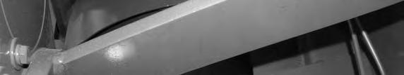
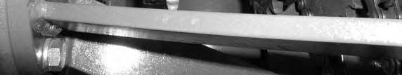
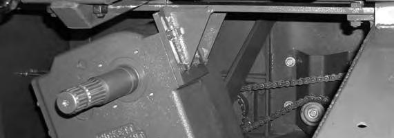
6 # Instructions for mounting transmission on a 2001 to Present DMP (use with Kit # s and ) 1. Remove driveline from end of threshing cylinder. Alignment jig (part # ) will need to fit on shaft a minimum of 2 in most cases. The sprocket will also need to be removed from the cylinder shaft to allow the proper fit of the alignment jig. (Figure 1) 2. Unbolt flow divider and synchronizing valve. (Figure 2) 3. An access through the walkway will make installation and maintenance easier this should be approximately 18 x 36. Use extreme care not to cut any wires or hydraulic hoses. Weld strips under the walkway as shown, then place piece removed back in place and mark holes from bottom side, drill holes and set aside. (Figure 3) 4. The 3-1/8 x 4-3/4 tube (Cut flow divider mount off and save till later) and sheet metal angle under the walkway can now be removed. (Figure 2) A. * 5. Bolt transmission mounting plate (part # ) to transmission mounting jig assembly (part # ) Slide jig and mount assembly onto the end of the threshing cylinder shaft until jig stops at shoulder on the inside of the jig this will make the front of the transmission mounting plate 8-1/2 from the end of the threshing cylinder shaft. Start with the mounting jigs four bolt holes at 12, 3, 6, and 9 o clock positions. Now rotate the assembly counterclockwise 20. (As viewed from the front of the combine looking back). (Figure 4) 6. You can now place the flat bar supports in place (Top Support Plates # ), (Bottom Support Plates #510262). Use care to leave room for the drive chain for the feeder auger and the coupling sprockets. (Figures 5 & 6) 7. Weld supports to combine and transmission mount only, jig # will be removed after all welding is done and cooled. (Figure 7) 8. Drive sprocket and chain for the feeder auger can now be installed and tightened. (Figure 7) 9. Next install one of the 60B20 x 1-3/4 sprockets (Part # ) flush with the end of the cylinder shaft, but do not tighten at this time. (Do not force sprocket onto the shaft as it may need to be aligned later. (Figure 8) 10. Before installing the transmission (Part # ), fit the 60B20 x 2-1/8 sprocket (Part # ) and 1/2 keystock to the transmission shaft, and set sprocket aside. Transmission can now be installed on the combine. After transmission is securely mounted sprocket can be placed on transmission shaft but do not tighten. (Figure 8) 11. The remaining two 60B20 x 1-3/4 (Part # ) sprockets can now be placed on the 2-3/4 long coupling shaft (Part # ), align sprocket faces with the ends of the shaft. Install coupling shaft assembly between the transmission shaft and cylinder shaft using coupling chains (Part # ). Align sprockets to remove any side load on the coupling chains. Set screws in the sprockets can now be tightened. B. * (Figure 9) 12. Transmission stabilizer (Part # ) can now be installed. (Figure 10 & 11) 13. Weld flow divider mount that was removed in Step 4 on to the transmission stabilizer (Part # ). 6
7 14. Reinstall flow divider, synchronizing valve, hose holder (Part # ) and hoses. C. * 15. Install drivelines (Part # , & ), check oil level in transmission, check for loose or missing bolts and bolt center part of walkway into place. D.* 16. You are now ready to hook combine to a tractor and test run. *If changing tongue to DMP SP read the following special instructions. Before removing hitch, be sure to securely block all four corners of the combine. It will become extremely back heavy without the tongue. Removing the original tongue before proceeding with transmission installation will allow easer access. A. * The 3-1/8 x 4-3/4 tube will not need to be removed in this application, but you will need to cut the flow divider mount off and save till later and remove the sheet metal angle under the walkway. B. * Pull Tongue Hitch assembly # and Pull Tongue # will need to be installed before proceeding. C. * Hoses and Dickey-john monitor cable will need to be lengthened. D. *Install drivelines (Part # , & ). 7


8 Figure 1 Figure 2 Save this mount Remove this tubing Figure 3 Figure 4 Figure 5 8


9 Figure 6 Figure 7 Figure 8 Figure 9 Figure 10 Figure 11 9
10
11 SERVICE UPDATE KITS Model 2000 Double Master Plus 2 Speed Transmission with Offset Pull Tongue Hitch Kit # Parts List Item No. Part No. Qty Description Pull Tongue Hitch (2000 Model Only) Pull Tongue Speed Transmission (complete) Transmission Mounting Jig (40mm female receiver) Transmission Mounting Plate Pull Tongue Swivel Pin Hydraulic Hose Carrier Driveline, Primary (1-3/4 20 Spline to 1-3/8 21 Spline) Driveline, Front Secondary (1-3/8 21 Spline to 1-3/4 Overrunning Clutch) Driveline, Rear Secondary (1-3/4 20 Spline to 1-3/4 20 Spline) Splined Shaft Carrier Splined Shaft (1-3/4 20 Spline to 1-3/4 20 Spline) Bearing, 45mm Insert Flange, 45mm (4 hole Round) PTO Swivel Gear Box Front Mounting Plate (Swivel Gear Box) Draw Bar Extension (for use with 1-3/ PTO Tractors) Draw Bar Extension (for use with 1-3/ PTO Tractors) Dura-Ball Hitch Dura-Ball Top Plate Dura-Ball Spacer Pickup Head Ram Mount Jack, Sidewinder Dickey-john Cable Extension (not shown) Quick Couplers (not shown) Adapter, Hydraulic ( ) (not shown) Hose, Hydraulic (8M2T-10FJ10FJ-16400) (not shown) Hose, Hydraulic (6M2T-8MP8MP-24500) (not shown) Cylinder, Hydraulic 3 x 8 (ASAE) Shift Lever Kit (2 Speed Transmission) Sprocket, 60B20 x 1-3/4 (not shown) Sprocket, 60B20 x 2-1/8 (not shown) Chain, 60B20 Coupler (not shown) Shaft, Coupler (1-3/4 O.D. Shaft 2-3/4 Long) (not shown) Stabilizer Mount (PTO Swivel Gear Box) Sprocket, 60B20 x 40mm (not shown) Ram Mount Plate (use with item # 22) Lift Arm Mount Plate (use with item # 22) Lift Arm Mount Gusset (use with item # 22) Top Support Plate (2 Speed Transmission) Bottom Support Plate (2 Speed Transmission) Mounting Instructions (2 Speed Transmission / Model 2000 only) Hardware List Item No. Part No. Qty Description A /2 x 6-1/2 NC Hex Bolt (with Lockwasher & Nut) B x 9 NC Hex Bolt (with Lockwasher & Nut) C /4 x 9 NC Hex Bolt (with Lockwashers & Nuts) D /4 x 5-1/2 NC Hex Bolt (with Lockwashers & Nuts) E Connection Link 60-2 F. 1 3/8 Keystock (2-3/4 Long) G. 1 5/16 Keystock (3-7/8 Long) H. 1 1/2 Keystock (2-1/2 Long) Revised January,
12
13 Model 2000 Double Master Plus 2 Speed Transmission with Mounting Kit # SERVICE UPDATE KITS Parts List Item No. Part No. Qty Description Speed Transmission (complete) Transmission Mounting Jig (40mm female receiver) Transmission Mounting Plate Driveline, Primary Driveline, Secondary Pickup Head Ram Mount Shift Lever Kit (2 Speed Transmission) Pickup Head Ram Mounting Plate Top Support Plate (2 Speed Transmission) Bottom Support Plate (2 Speed Transmission) Sprocket, 60B20 x 1-3/4 (not shown) Sprocket, 60B20 x 2-1/8 (not shown) Chain, 60B20 Coupler (not shown) Shaft, Coupler (1-3/4 O.D. Shaft 2-3/4 Long) (not shown) Sprocket, 60B20 x 40mm (not shown) Mounting Instructions (2 Speed Transmission / Model 2000 only) Hardware List Item No. Part No. Qty Description A. 4 5/8 x 2 NC Hex Bolt B. 4 5/8 Lockwasher C Connection Link 60-2 D. 1 3/8 Keystock (2-3/4 Long) E. 1 5/16 Keystock (3-7/8 Long) F. 1 1/2 Keystock (2-1/2 Long) Revised January,
14 # Instructions for mounting transmission on a 2000 DMP combine (use with Kit # s and ) 1. Remove driveline from end of threshing cylinder. Alignment jig (Part # ) will need to fit on shaft a minimum of 2 in most cases the sprocket will also need to be removed from the cylinder shaft to allow the proper fit of the alignment jig. (Figure 1) 2. Unbolt walkway and set aside remove pickup head lift ram and set aside. 3. The 3-1/8 x 4 3/4 tube with the stationary ram mount for the pickup head can now be removed. (Figure 2) A. * 4. Bolt transmission mounting plate part # to transmission mounting jig assembly part # Slide jig and mount assembly onto the end of the threshing cylinder shaft until jig stops at shoulder on the inside of the jig this will make the front of the transmission mounting plate 8-1/2 from the end of the threshing cylinder shaft. Start with the mounting jigs four bolt holes at 12, 3, 6, and 9 o clock positions. Now rotate the assembly counterclockwise 20. (As viewed from the front of the combine looking back). (Figure 3) 5. You can now place the flat bar supports in place (Top Support Plates # ) (Bottom Support Plates # ). Use care to leave room for the drive chain for the feeder auger and the coupling sprockets. (Figures 4 & 5) 6. Weld supports to combine and transmission mount only, jig # will be removed after all welding is done and cooled. (Figure 6) 7. Drive sprocket and chain for the feeder auger can now be installed and tightened. (Figure 6) 8. Next install the 60B20 x 40 mm sprocket (Part # ) flush with the end of the cylinder shaft, but do not tighten at this time. (Do not force sprocket onto the shaft as it may need to be aligned later. (Figure 7) 9. Before installing the transmission (Part # ) fit the 60B20 x 2-1/8 sprocket (Part # ) and 1/2 keystock to the transmission shaft, and set sprocket aside. Transmission can now be installed on the combine. After transmission is securely mounted sprocket can be placed on transmission shaft but do not tighten. (Figure 7) 10. The two 60B20 x 1-3/4 sprockets (Part # ) can now be placed on the 2-3/4 long coupling shaft (Part # ), align sprocket faces with the ends of the shaft. Install coupling shaft assembly between the transmission shaft and cylinder shaft using coupling chains (Part # ). Align sprockets to remove any side load on the coupling chains. Set screws in the sprockets can now be tightened. (Figure 8) B.* 11. Combination transmission stabilizer/pickup head ram mount (Part # ) can now be installed. Position mount were ram is fully extended when chain hooks are down. (Figure 9) C. * 12. Install drivelines (Part # s & ), check oil level in transmission, check for loose or missing bolts and bolt the walkway into place. D. * 13. You are now ready to hook combine to a tractor and test run. 14
15 *If changing tongue to DMP SP read the following special instructions. Before removing hitch, be sure to securely block all four corners of the combine. It will become extremely back heavy without the tongue. Removing the original tongue before proceeding with transmission installation will allow easer access. A. * The 3-1/8 x 4-3/4 tube will not need to be removed in this application because the entire tongue is removed. Unbolt Pickup head lift assembly and set aside. B. * Pull Tongue Hitch assembly # and pull tongue # will need to be installed before proceeding. Pickup head lift assembly can now be bolted into place. (If mounts for lift assembly are not on hitch assembly refer to Diagram A.) Position mount were ram is fully extended when chain hooks are down. C. * Dickey-john monitor cable will need to be lengthened. Remove steel hydraulic lines that were on the pull tongue sides and replace with extended hydraulic hoses. D. * Install drivelines (Part # s , & ). 15


16 Figure 1 Figure2 Remove tubing with ram ear Figure 3 Figure 4 Figure 5 Figure 6 16
17 Figure 7 Figure 8 Figure 9 17
18
19 This page was left blank intentionally 19
20
21 2 Speed Transmission Shift Lever Kit # Twin Master Combine Parts List Item No. Part No. Qty Description Shift Lever Shift Lever Mount Shift Lever Swivel Adapter Hardware List Item No. Part No. Qty Description A /16 Bridge Pin B. 1 3/8 x 2 NC Hex Bolt C. 1 3/8 NC Hex Nut D. 1 7/16 x 3 NC Hex Bolt E. 1 7/16 NC Nyloc Hex Nut (not shown) F. 1 1/2 x 3 NC Hex Bolt G. 1 1/2 NC Stover Hex Nut (not shown) Revised January,
22 Swing Tonuge Jack Update Kit 6 5/32" 67" A 11/32" A /16" 11/32" A
23 Jack Update Kit # Service Update Kits DMP- SP2 and Twin Master Parts List Item No. Part No. Qty. Description Combine Jack A 2 Jack Mounting Plate Jack Mount Spacer Tube PTO Mount Spacer /2 Flat Washer /2 x 1 1/2 Hex Bolt /2 Whiz Nut x 6 1/2 Top Hitch Pin Revised June,
24 Rear Ladder Kit /4" 2 3/4" Measure From Bend 13/32" 6 Places 6 1/2" 17/32" 2 Places 3/4" 3" 1/2" 9 3/4" 10 1/4" 9 3/4" 20"
25 Rear Ladder Kit # Service Update Kits Parts List Item No. Part No. Qty. Description Twin Master A 1 Rear Ladder Assembly Rear Ladder Mounting Assembly A 1 Rear Ladder Latch Base A 1 Rear Ladder Catch Revised November,
26 Clamps 2-1/4" x 1 1/2" x 1 1/2" Spacer Elevator Door Hinge Pipe 2-1/2" x 2 1/2" Keystock Elevator Door Hinge Pin 4-3/16" x 1" Cotter Key Elevator Leg Hinge Pipe Elevator Hinged Door Kit
27 Tack weld hinge and latch into place before removing the bolts holding the door closed Front of Combine --> right elevator leg shown Center hinge on elevator leg Weld short hinge pieces to elevator leg Weld long hinge piece to door Weld short hinge pieces to elevator leg Center hinge pieces on elevator leg and weld to the elevator door and the elevator leg (see rear view) Sheet 2
28 /16" 4 15/16" Center latch in the center of the elevator leg This end of the latch should be even with top of the flat bar Place 1/2" keystock under this end of the latch 5 3/8" 5 3/8" 1/4" x 1 1/2" x 1 1/2" spacer centered under catch 2 3/8" 2 3/8" This end of the catch should be against the flat bar After all pieces are tacked into place remove the original bolts and finish welding all parts Sheet 3
29 ITEM NO. PART NUMBER DESCRIPTION QTY Shaker Mount Support Plate Shaker Mount Assembly RFC 35mm Flange UC mm Bearing Shaker A Arm Assembly 1 Kit to Update DMP Shaker Tables to 2009 Bearing Style Hardware Required: 8-1/2" x 1-1/2" Hex Bolts 8-1/2" Wiz Nuts 8-3/8" x 1" Hex Bolts 8-3/8" Wiz Nuts 8-3/8" Flat Washers Kit #
Twin Master Combine. Threshing Cylinder Section 1. Threshing Cylinder ( ) Threshing Cylinder (2009 Present)...
 Threshing Cylinder (2009 Present)...") Threshing Cylinder Section 1 Threshing Cylinder (2006 2008)... 2-8 Threshing Cylinder (2009 Present)... 9-15 Return to this page by clicking the upper right corner of any page in this section. Revised
Threshing Cylinder Section 1 Threshing Cylinder (2006 2008)... 2-8 Threshing Cylinder (2009 Present)... 9-15 Return to this page by clicking the upper right corner of any page in this section. Revised
Universal Platform. 246 Model Section 4. Platform Parts Breakdown (1997 Present) Retractable Finger Auger Parts Breakdown...
 Retractable Finger Auger Parts Breakdown...") Universal Platform 246 Model Section 4 Platform Parts Breakdown (1997 Present)... 2-4 Retractable Finger Auger Parts Breakdown... 5-6 Combine Pickup Head Parts Breakdown (1997 Present)... 7-10 4 Tube Pickup
Universal Platform 246 Model Section 4 Platform Parts Breakdown (1997 Present)... 2-4 Retractable Finger Auger Parts Breakdown... 5-6 Combine Pickup Head Parts Breakdown (1997 Present)... 7-10 4 Tube Pickup
Universal Platform. 222 Model Section 3. Platform Parts Breakdown (1997 Present) Retractable Finger Auger Parts Breakdown...
 Retractable Finger Auger Parts Breakdown...") Universal Platform 222 Model Section 3 Platform Parts Breakdown (1997 Present)... 2-4 Retractable Finger Auger Parts Breakdown... 5-6 Combine Pickup Head Parts Breakdown (1997 Present)... 7-10 4 Tube Pickup
Universal Platform 222 Model Section 3 Platform Parts Breakdown (1997 Present)... 2-4 Retractable Finger Auger Parts Breakdown... 5-6 Combine Pickup Head Parts Breakdown (1997 Present)... 7-10 4 Tube Pickup
Universal Platform. 282 Model Section 5. Platform Parts Breakdown Retractable Finger Auger Parts Breakdown
 Universal Platform 282 Model Section 5 Platform Parts Breakdown... 2-3 Retractable Finger Auger Parts Breakdown... 4-5 Combine Pickup Head Parts Breakdown... 6- Return to this page by clicking the upper
Double Master Plus Combine
 Pickup Head Section 3 Pickup Head Straight Pull (2001 20)... 2-7 Pickup Head DMP SP2 (2006 2008)... 8-10 Pickup Head DMP SP2 (20 2014)... 11-13 Pickup Head DMP & DMP SP (2010 2014)... 14-16 Pickup Head
One Step Ahead Rod Cutter (Front Mount Unit)
") One Step Ahead Rod Cutter (Front Mount Unit) Pickup Head Layouts Section 7 Model Years 1992 1993... 2-3 Model Years 1994 1996... 4-5 Model Years 1997 Present (4 Tube)... 6-7 Model Years 1997 2013 (8 Tube)...
One Step Ahead Rod Cutter (Front Mount Unit) Pickup Head Layouts Section 7 Model Years 1992 1993... 2-3 Model Years 1994 1996... 4-5 Model Years 1997 Present (4 Tube)... 6-7 Model Years 1997 2013 (8 Tube)...
One Step Rod Cutter Rear Pull
 One Step Rod Cutter Rear Pull Drivelines Section 13 Model Years 1988 1991 (Secondary Driveline) 1 Solid Shaft... 2-5 Model Years 1988 1992 (Primary Driveline) G & G... 6-11 Model Year 1992 (Secondary Driveline)
Twin Master Combine. Hydraulic Systems Section 11. Hydraulic Systems ( ) Hydraulic Systems (2008 Present)
 Hydraulic Systems (2008 Present)") Twin Master Combine Hydraulic Systems Section 11 Hydraulic Systems (2006 2007)... 2-5 Hydraulic Systems (2008 Present)... 6-9 Return to this page by clicking the upper right corner of any page in this
Twin Master Combine Hydraulic Systems Section 11 Hydraulic Systems (2006 2007)... 2-5 Hydraulic Systems (2008 Present)... 6-9 Return to this page by clicking the upper right corner of any page in this
MODELS 470, 570, 670, 770 Corner Auger GRAIN CART (For Model 970 Information, Refer to Manual #250541)
") OPERATOR S MANUAL PARTS CATALOG MODELS 470, 570, 670, 770 Corner Auger GRAIN CART (For Model 970 Information, Refer to Manual #250541) PART NO. 250611 200026 Late Model 70 Series 290374 Early Model 70
OPERATOR S MANUAL PARTS CATALOG MODELS 470, 570, 670, 770 Corner Auger GRAIN CART (For Model 970 Information, Refer to Manual #250541) PART NO. 250611 200026 Late Model 70 Series 290374 Early Model 70
Twin Master Combine. Transmission & Gear Boxes Section 8. 2 Speed Transmission Transmission Gear Shift
 Twin Master Combine Transmission & Gear Boxes Section 2 Speed Transmission... 2-4 Transmission Gear Shift... 5-6 PTO Swivel Gear Box 107021... 7- Transition Auger Gear Box 107026... 9-10 Straw Chopper
Combine Pickup Heads
 Combine Pickup Heads Torsion Combine Pickup Heads Section 6 30 ft. Torsion Combine Pickup Head... 2-5 24 ft. Torsion Combine Pickup Head... 6-9 Return to this page by clicking the upper right corner of
One Step Ahead Rod Cutter (Front Mount Unit)
") One Step Ahead Rod Cutter (Front Mount Unit) Front Gauge Wheels Section 4 Model Years 1992 1994... 2-5 Model Years 1995 1996... 6-9 Model Years 1997 Present... 10-11 Front Gauge Wheel Divider 1992 Present...
One Step Ahead Rod Cutter (Front Mount Unit) Front Gauge Wheels Section 4 Model Years 1992 1994... 2-5 Model Years 1995 1996... 6-9 Model Years 1997 Present... 10-11 Front Gauge Wheel Divider 1992 Present...
Combine Pickup Heads
 Combine Pickup Heads 164 Model Section 3 Model Years 1991 1996... 2-5 Pickup Head Layout 1994 1996... 6-7 Model Years 1997 1999 (1 PUH Bearings)... 8-10 4 Tube Pickup Head Layout 1997 1999... 11-12 Model
Combine Pickup Heads
 Combine Pickup Heads 124 Model Section 1 Model Years 1991 1996... 2-5 Pickup Head Layout 1994 1996... 6-7 Model Years 1997 1999 (1 PUH Bearings)... 8-10 4 Tube Pickup Head Layout 1997 1999... 11-12 Model
62 Deck Idler Kit High Speed
 Part No. 00 FORM NO. -899 6 Deck Idler Kit High Speed For Model 70 Serial No. 99000 to 99000 For Model 7 Serial No. 9900 to 99000 INSTALLATION INSTRUCTIONS Loose Parts Note: Use the chart below to identify
1 HR-301/D Parts Manual. Table Of Contents
 Table Of Contents 301/D Parts Manual 3 Point Hitch...2 Pull-Type Hitch...4 Main Frame...6 Angle Adjuster - Serial Number 44982 & Prior...8 Rotor Assembly - Serial Number 44982 & Prior...10 Rotor Assembly
ALL PLANT & MIN TILL DRILL
 4000 SERIES ALL PLANT & MIN TILL DRILL OWNER S MANUAL ADDENDUM OPERATION MAINTENANCE REPAIR PARTS #608869 (03-08) 2 Table of Contents Precision Planting Metering System 5-9 Precision Planting Introduction
One Step Ahead Rod Cutter (Front Mount Unit)
") One Step Ahead Rod Cutter (Front Mount Unit) Pickup Head Gear System (LH End View) Section 6 Model Years 1992 1998... 2-3 Model Years 1998 1999 (1 PUH Bearing)... 4-6 Model Years 1998 2012 (1 1/4 PUH Bearing)...
One Step Ahead Rod Cutter (Front Mount Unit) Pickup Head Gear System (LH End View) Section 6 Model Years 1992 1998... 2-3 Model Years 1998 1999 (1 PUH Bearing)... 4-6 Model Years 1998 2012 (1 1/4 PUH Bearing)...
SECTION V ASSEMBLY CAUTION THE FOLLOWING SAFETY PRECAUTIONS SHOULD BE THOROUGHLY UNDERSTOOD BEFORE ATTEMPTING MACHINE ASSEMBLY.
 SECTION V ASSEMBLY CAUTION THE FOLLOWING SAFETY PRECAUTIONS SHOULD BE THOROUGHLY UNDERSTOOD BEFORE ATTEMPTING MACHINE ASSEMBLY. 1. Wear personal protective equipment such as, but not limited to protection
This page was. left blank. intentionally
 This page was left blank intentionally 2 Revised June, 2017 ONE STEP ROD CUTTER (Rear Pull Unit) CONTENTS Chain Case Section 1 Model Years 1988 1990 (PTO Drive Chain Case)... 2 Model Year 1991 (PTO Drive
PARTS MANUAL THIS PAGE INTENTIONALLY LEFT BLANK. Ag-Bag International, Ltd. G7000 June Appendix A
 The parts manual is organized into groups, it is designed to make the locating of parts easier. The exploded drawings also show assembly paths. All parts listed are available from your authorized Ag-Bag
Installation Guide CLAAS Lexion Combines with 9 inch Elevators
 Installation Guide CLAAS Lexion Combines with 9 inch Elevators 955614_01 4/17 1 Table of Contents System Overview 3 Quick Start Guide 4 Flow Sensor Installation 5 Hydraulic Elevator Adjustment Kit Installation
Retriever 360G/P. 5/92 revised 2/01 FORM NUMBER
 Retriever 360G/P PARTS LIST Advance MODELS 56468470, 56468480 This parts list is for machines after serial number 505073 All models covered in this manual are OBSOLETE 5/92 revised 2/01 FORM NUMBER 56042267
General Information. Veris Drive Option
 No-Till and No-Till Precision Seeding System Used with: 3N-3010P and 3N-3020P 3N-3010 and 3N-3020! When you see this symbol, the subsequent instructions and warnings are serious - follow without exception.
Lime Spreader. Model SL6. Illustrated Parts Breakdown. Front Hydraulics Rear Hydraulics Manifold Components. Spinner Assembly
 Lime Spreader Model SL Illustrated Parts Breakdown Page Page Page Page Page Page Page Page Page Page 0 Front End Front Hydraulics Rear Hydraulics Manifold Components Floor & Apron Axle Assembly Apron Drive
Model 10 Actuator with Leveler Channel. Model 10 Actuator with Leveler Channel and Mounting Channel For 3 Width Tongue
 Basic capacity 0,000 lbs. G.V.W.R., 800 lbs. tongue load The Model 0 is demountable when installed with mounting channel for width tongue or may be welded for permanent installation. This actuator is available
250P Manure Spreader
 0P Manure Spreader Illustrated Parts Breakdown Page - Page Page Page Page Page Page Page Page Page Page Page Page Page Page - Page Page Page 0 Complete Front End PTO/Jack/Hitch Assembly Front Pulley Assembly
Section K WC1335 AND WC15 SERIES CONVEYORS TUBE / UNDERCARRIAGE / DRIVE INDEX
 INDEX Section K WC33 AND WC SERIES CONVEYORS TUBE / UNDERCARRIAGE / DRIVE Description Page WC33 basic conveyor... K2-3 WC basic transfer... K4- WC70 basic tube... K-7 WC80 basic tube... K8-9 WC90 basic
DAVIMAC CHASER BIN PARTS LIST
 DAVIMAC CHASER BIN PARTS LIST FROM: 0 CB TO 9 DAVIMAC PTY LTD WELINGTON STREET MOLONG NSW STANDARD CHASER BIN - RIGHT 0 8 9 000 CHASSIS -8 008 BIN 9-0 0000 AUGER -8 000 STEP BOLTED - 000-0 BIN TO CHASSIS
Drive End Bracket & Bearing. Drive End Bracket. Tandem Axle # #865733
 Drive End Bracket & Bearing #865089 1 06409700 1" Lock Collar 2 865733 Drive Bracket w/ Bearing 3 310037 End Drive Shaft Drive End Bracket #865733 1 03003100 Bearing 1" w/snap Ring 2 957795 Drive End Bracket
1 RS-300/D 320/D 340/D 350H Parts Manual
 300/D 320/D 340/D 350H Parts Manual Table Of Contents Three Point Hitch / Hitch Frame Assembly... 3 Tongue Pull Hitch Assembly... 7 Main Gearbox... 11 Crank Handle & Gear... 13 Hydraulic Lift... 15 Rotor
Receiver Hitch & Towing System Quic n Easy Receiver Hitch & Quic-Cush n II Towing System
 Receiver Hitch & Towing System Quic n Easy Receiver Hitch & Quic-Cush n II Towing System Does your Hitch need an upgrade? Quic n Easy Call with your Extends to 7. Swings to 12. Year, Make & Model Fits
Safety Assembly Operation Service and Adjustment Repair Parts 1602 CORPORATE DRIVE, WARRENSBURG, MISSOURI PHONE FAX
 swisherinc.com OWNER S MANUAL MODEL NO. LS622 LS826 LS934 LS10534D LOG SPLITTER IMPORTANT Read and follow all Safety Precautions and Instructions before operating this equipment. Rev.07.04.2001 Safety
Safety First. Please remember to always use SAFE shop practices when performing all service procedures.
 Safety First Please remember to always use SAFE shop practices when performing all service procedures. 2006 Update Manual January 2006 Country Clipper 2006 Update Manual Index Joystick Kill Switch Oil
INSTALLATION INSTRUCTIONS
 INSTALLATION INSTRUCTIONS 6525 REAR AXLE FLIP & HANGER KIT 5 OR 6 INCH LOWERING 14&UP CHEVROLET SILVERADO / GMC SIERRA 1500 Thank you for being selective enough to choose our high quality BELLTECH PRODUCT.
GSN-8 Spreader. Illustrated Parts Breakdown. Page 1 Front End Assembly Page 2 Axle Assembly Page 3 Floor & Apron Page 4 Pump Assembly
 GSN- Spreader Illustrated Parts Breakdown Page Front End Assembly Page Axle Assembly Page Floor & Apron Page Pump Assembly Page Hydraulics Page Manifold Components Page Manifold Cover Page Gearbox Components
DODGE SuperRail Mounting Kit #0848
 DODGE SuperRail Mounting Kit #0848 #1200 Super 5 th (16K) #0800 Super 5 th (20.5K) Gross Trailer Weight (Maximum) Vertical Load Weight (Max. Pin Weight) 16,000 lbs. 4,000 lbs. Gross Trailer Weight (Maximum)
Litter Spreader. Models SP400, SP450, SP500, SP550. Illustrated Parts Breakdown
 Litter Spreader Models SP00, SP0, SP00, SP0 Illustrated Parts Breakdown Page Front End Page Hydraulic System (w/ Side Mounted Reservoir) Page Hydraulic System (w/ Front Mounted Reservoir) Page Hydraulic
Mulching and Finishing Mowers MP and FP
 Mulching and Finishing Mowers MP and FP Parts Manual Locke Turf 0 Highway E, Opp, Alabama, () -00 Transport Wheel, Tire & Spindle MP and FP ALPHABETICAL INDEX CONTENTS PAGE 00 Hydraulic Cylinder (Rear)
Electronic Service Manuals
 Electronic Service Manuals This electronic document is provided as a service to our customers. We do not create the contents of the information contained in this document. Should you have detailed questions
Model 802 Center Mount Adapter For New Holland 9030 & TV140 Bi-Directional Tractors PARTS CATALOG
 Model 802 Center Mount Adapter For New Holland 9030 & TV140 Bi-Directional Tractors 1 PARTS CATALOG TABLE OF CONTENTS Frame & Tractor Linkage...2,3 Header Linkage & Float Group...4,5 Header Drive Hydraulics
NEVER STOP CORRUGATE OPENER
 NEVER STOP CORRUGATE OPENER CORRUGATE OPENER PRE.-DELI VERY SET UP The Never Stop has been fully assembled and tested prior to delivery. Upon receipt of this machine it is necessary to check and tighten
Electronic Service Manuals
 Electronic Service Manuals This electronic document is provided as a service to our customers. We do not create the contents of the information contained in this document. Should you have detailed questions
Illustrated Parts & Packing List 528 Gandrud Road, Owatonna, MN For a complete distributor & dealer list go to
 Illustrated Parts & Packing List 528 Gandrud Road, Owatonna, MN 55060 For a complete distributor & dealer list go to www.gandy.net 66GW27F Orbit-Air Applicator 120 Cu. Ft. Hopper w/ 27 (2 ) Openings, Fertilizer
ROW CROP MANAGER CONTENTS
 ROW CROP MANAGER CONTENTS Complete Parts Breakdown Section 1 Row Crop Manager (Exploded View)...4 Folding Wing (Exploded View)...8 Adjustable Row Module Section 2 Row Module (Exploded View)...12 V-Guide
521613x89A Garden Tractor (2001) Page 1 of 24 Blade Drive
 Page 1 of 24 Blade Drive") 521613x89A Garden Tractor (2001) Page 1 of 24 Blade Drive 521613x89A Garden Tractor (2001) Page 2 of 24 Blade Drive Ref # Part Number Qty Description 1 094607E701 Cover, Right Pulley 2 26X250 Screw 3 015X84
521613x89A Garden Tractor (2001) Page 1 of 24 Blade Drive 521613x89A Garden Tractor (2001) Page 2 of 24 Blade Drive Ref # Part Number Qty Description 1 094607E701 Cover, Right Pulley 2 26X250 Screw 3 015X84
EVO-1162 EVO Tailgate Tire Carrier
 EVO-1162 EVO Tailgate Tire Carrier Bill of Materials EVO-1162 Tailgate Tire Carrier Part number Description Quantity EVO-12161 EVO Tailgate Tire Carrier 1 EVO-12162 Bolt Plate 1 EVO-12163 Wheel Mount 1
320 Series Models 325, 326, 327
 0 Series Models,, ROTARY MOWER Published 0/ PARTS MANUAL SECTION An Operator s Manual was shipped with the equipment. The Operator s Manual is an integral part of the safe operation of this machine and
INFEED HOPPER COMPONENTS. Parts may not be exactly as shown. Bandit. Copyright 1/12
 INFEED HOPPER COMPONENTS 80 INFEED HOPPER COMPONENTS 1. 626-200019 Folding Pan for Infeed Hopper 2 a. 900-4901-83 Folding Pan Spring Lock & Trap Door Lock b. 900-7900-93 Black Rubber Cap (Not Shown) 3
ARCHIVE BOOK - II AG20-IV / AG14-IV ROTARY FLEX WING MOWER
 AG0-IV / AG-IV ROTARY FLEX WING MOWER ARCHIVE BOOK - II By Serial Number / Production Book = Apr. 99 s/n AG0-0300 Jun. 00 AG0-IV Model - 0' Flex Wing Rotary AG-IV Model - ' Flex Wing Rotary COMPLETE PARTS
FX90 Skidding Winch Parts Manual S/N and After
 Z9056 FX90 Skidding Winch Parts Manual S/N 5906 and After Foreword EMB Mfg. has prepared this parts manual to assist customers in ordering quality OEM replacement parts. Proper and regular service and
HR24TS Rotary Rake. Serial Numbers and higher. Illustrated Parts Breakdown. Guards and Guard Arm, Front Hay Curtain Mount.
 HRTS Rotary Rake Serial Numbers 00 and higher Illustrated Parts Breakdown Page Page Page Page Page Page Page Page Page Page 0 Page Page Page Page Page Page Page Page Page Page 0 Tongue Front Frame Guards
FORAGE WAGONS STRENGTH / QUALITY / PERFORMANCE
 FORAGE WAGONS STRENGTH / QUALITY / PERFORMANCE FORAGE WAGONS 7.8 25m 3 MULTICROP 7.8-20m 3 You expect your farm machinery to go the distance, and McIntosh delivers with Forage Wagons built to the highest
Universal Mounting Kit #0820
 Universal Mounting Kit #0820 #1200 Super 5 th (16K) #0800 Super 5 th (20.5K) Gross Trailer Weight (Maximum) Vertical Load Weight (Max. Pin Weight) 16,000 lbs. 4,000 lbs. Gross Trailer Weight (Maximum)
Main Frame (1,676 MM (5-1/2 FT.) Hay Pickup)
 Hay Pickup)") Main Frame (,676 MM (5-/2 FT.) Hay Pickup) 2 E34250 STRIPPER 2-3000 AUGER E66297 ANGLE 2 300- AUGER, (SUB FOR E34496) (SUB E9572) E9572 ANGLE 2 AUGER E6905 TUBE 59400-86 Pickup Heads Strippers (,676 MM
Main Frame (,676 MM (5-/2 FT.) Hay Pickup) 2 E34250 STRIPPER 2-3000 AUGER E66297 ANGLE 2 300- AUGER, (SUB FOR E34496) (SUB E9572) E9572 ANGLE 2 AUGER E6905 TUBE 59400-86 Pickup Heads Strippers (,676 MM
FX65 Skidding Winch Parts Manual. Prior to S/N
 FX65 Skidding Winch Parts Manual Prior to S/N 5654 Foreword EMB Mfg. has prepared this parts manual to assist customers in ordering quality OEM replacement parts. Proper and regular service and replacing
<THESE INSTRUCTIONS MUST BE GIVEN TO THE END USER> B&W
 B&W Trailer Hitches 1216 Hawaii Rd / PO Box 186 Humboldt, KS 66748 Turnoverball Gooseneck Hitch Installation Instructions MODEL 1314 2013 2014 RAM 3500
Lime Spreader. Model SL6. Illustrated Parts Breakdown. Front Hydraulics Rear Hydraulics Manifold Components. Spinner Assembly
 Lime Spreader Model SL Illustrated Parts Breakdown Page Page Page Page Page Page Page Page Page Page 0 Front End Front Hydraulics Rear Hydraulics Manifold Components Floor & Apron Axle Assembly Apron Drive
Model 873 COMBINE ADAPTER
 Model 873 COMBINE ADAPTER For 963, 972, 973 & 974 Headers on: Case Combines New Holland Combines John Deere Combines Lexion Combines Agco Combines PARTS CATALOG Form 147071 Issue 09/06 Sugg. Retail: $10.00
2720/12720 PARTS MANUAL 72A SECTION FLEX WING ROTARY MOWER
 0/0 This Manual applies to models 0 and 0 that use a blade pan which measures. blade hole center to blade hole center. Also blades measure 8. from hole center to blade tip. See Section if these dimensions
PARTS BOOK John Deere Twin Fan 640/645FD
 Parts Order Information PARTS BOOK John Deere Twin Fan 640/645FD Contact Info: TEMP Farm Equipment Ltd. 3890 Wellington St. Box 269 Mitchell, Ontario, Canada N0K-N0 Phone: -877-348-0066 or 59-348-0066
BUSH HOG LAND MAINTENANCE REPAIR PARTS MANUAL MODEL: 3414 SECTION: 67
 BUSH HOG LAND MAINTENANCE REPAIR S MANUAL MODEL: SECTION: 0 Griffin Ave. Selma, AL 0 () - () -00 Parts Ordering -00-0- Fax -00-- www.bushhog.com BUSH HOG/ LAND MAINTENANCE REPAIR S MANUAL July, 0 ROTARY
DAVIMAC CHASER BIN PARTS LIST
 DAVIMAC CHASER BIN PARTS LIST FROM : CB7 TO CB667 DAVIMAC PTY LTD WELINGTON STREET MOLONG NSW CHASER BIN - RIGHT 9 9 6 0 7 8 9 8 0 000-06 REAR CHAIN BRACKET 00700 AUGER ASSEMBLY 0700 STANDARD AUGER SUPPORT
Model 960 Double Delivery and Triple Delivery HARVEST HEADERS PARTS CATALOG
 Model 960 Double Delivery and Triple Delivery HARVEST HEADERS PARTS CATALOG with Adapters for: Model 7000 Self-Propelled Windrower Model 9000 Self-Propelled Windrower John Deere 7720, 8820, 9500, 9600
Illustrated Parts & Packing List 815 Rice Lake Street, Owatonna, MN For a complete distributor & dealer list go to
 Illustrated Parts & Packing List 815 Rice Lake Street, Owatonna, MN 55060 For a complete distributor & dealer list go to www.gandy.net 6250BN36C Orbit-Air Applicator 50 Cu. Ft. Hopper w/ 26 (1-1/4 ) Openings,
Alignment Spec. Power Rack & Pinion: 5 degrees positive Camber 0 degrees Toe-In 1/32
 333-TCIE237 1967-1969 Chevy Camaro Front Suspension 1968-1972 Chevy Nova Front Suspension 1967-1969 Pontiac Firebird Front Suspension 1-800-984-6259 www.totalcostinvolved.com 1967-1969 Chevy Camaro Front
M K Martin Enterprise Inc. Price Lists Snowblower Parts for Farmco Distributors. Item No. Description List Price Inner Tube Roll PIn
 M K Martin Enterprise Inc. Price Lists Snowblower Parts for Farmco Distributors Item No. Description List Price 519-000-011 Inner Tube Roll Pin $1.03 519-000-012 Outer Tube Roll Pin $1.03 519-000-014 Inner
MODEL: 14T Automatic Baler
 John Deere MODEL: 14T Automatic Baler THIS IS A MANUAL PRODUCED BY JENSALES INC. WITHOUT THE AUTHORIZATION OF JOHN DEERE OR IT'S SUCCESSORS. JOHN DEERE AND IT'S SUCCESSORS ARE NOT RESPONSIBLE FOR THE QUALITY
BUSH HOG LAND MAINTENANCE REPAIR PARTS MANUAL MODEL: 405 / 406 SECTION: 17
 BUSH HOG LAND MAINTENANCE REPAIR S MANUAL MODEL: 0 / 0 SECTION: 0 Griffin Ave. Selma, AL 0 () - () -00 Parts Ordering -00-0- Fax -00-- www.bushhog.com BUSH HOG/ LAND MAINTENANCE REPAIR S MANUAL SEPTEMBER,
LAND MAINTENANCE REPAIR PARTS MANUAL BUSH HOG MODEL: 307 SECTION: 16
 BUSH HOG LAND MAINTENANCE REPAIR S MANUAL MODEL: 0 SECTION: P.O. Box 0 Selma, AL 0-0 () - () -00 Parts Ordering -00-0- Fax -00-- www.bushhog.com BUSH HOG / LAND MAINTENANCE REPAIR S MANUAL SEPTEMBER, 0
YARD TRACTOR ELECTRIC CLUTCH HYDRO DRIVE REAR DISCHARGE SERIES 0
 Parts Manual for YARD TRACTOR ELECTRIC CLUTCH HYDRO DRIVE REAR DISCHARGE SERIES 0 MODEL RD1740 (2690155) RD1840 (1694384) RD2040 (2690114) McDonough, GA, 30253 U.S.A. COPYRIGHT 2005 SNAPPER PRODUCTS, INC.
33 COMPACT DISC Ref. No. Part Name Part Number
 CONTENTS CONTENTS 33 COMPACT DISC Ref. Part Name Part Number 1 Tire & Rim 168025 2 Disc Axle 401036 3 Plastic End Cap (Pkg. 2) 504090 4 Sealed Bearings & Flanges 504125 5 Bearing Stand Bolt Pkg. (2-U-Bolts)
INSTALLATION INSTRUCTIONS
 INSTALLATION INSTRUCTIONS --1075 North Ave. Sanger, CA 93657-3539 local: 559-875-0222 fax: 559-876-2259 toll free: 800-445-3767-- 6522 REAR AXLE FLIP & SHACKLE KIT 07-UP CHEVROLET 1500 REGULAR CAB ONLY
<THESE INSTRUCTIONS MUST BE GIVEN TO THE END USER> B&W
 B&W Trailer Hitches 6 Hawaii Rd / PO Box 86 Humboldt, KS 66748 P:60.473664 F:60.869.903 Turnoverball Gooseneck Hitch Installation Instructions MODEL 08
MOUNTING INSTRUCTIONS JOHN DEERE GATOR NON-ROPS CAB
 MOUNTING INSTRUCTIONS JOHN DEERE GATOR NON-ROPS CAB FITS 4X2 & 6X4 GATORS A-11112, A-11224, A-11225, A-11226 MANUFACTURED BY: BOX 70 LITCHFIELD, MINNESOTA 55355-0070 (320) 693-3221 Fax: (320) 693-7252
PARTS LIST ROOFERS CONVEYOR
 PARTS LIST ROOFERS CONVEYOR TABLE OF CONTENTS ROOFERS CONVEYOR PAGE 2 & 3 ARTICULATING JOINT PAGE 11 HYDRAULIC CIRCUIT P..".8-9.55Y. PAGE 4 & 5 CONE ROLLER ARTICULATING JOINT PAGE 12 H-FRAME PAGE 6 ARTICULATING
PM25 & PM35 GRINDER MIXER ILLUSTRATED PARTS LIST
 PM25 & PM35 GRINDER MIXER ILLUSTRATED PARTS LIST Art s-way Manufacturing Co., Inc. 485140 1100 TO THE OWNER Congratulations on the purchase of your new Art s-way grinder mixer. You have selected a top
INSTRUCTIONS, (FORD) SUPER DUTY INSTALLATION KIT (C2 PICKUP LIFTGATES)
 SUPER DUTY INSTALLATION KIT (C2 PICKUP LIFTGATES)") LIFT CORPORATION Sht. 1 of 22 DSG# M-16-32 Rev. - Date: 12/13/16 INSTRUCTIONS, (FORD) SUPER DUTY INSTALLATION KIT (C2 PICKUP LIFTGATES) FORD SUPER DUTY F-250, F-350 & F-450 PICKUP TRUCKS, 2017 MODEL KIT
LIFT CORPORATION Sht. 1 of 22 DSG# M-16-32 Rev. - Date: 12/13/16 INSTRUCTIONS, (FORD) SUPER DUTY INSTALLATION KIT (C2 PICKUP LIFTGATES) FORD SUPER DUTY F-250, F-350 & F-450 PICKUP TRUCKS, 2017 MODEL KIT
GS12 Grape Spreader. Illustrated Parts Breakdown
 GS Grape Spreader Illustrated Parts Breakdown Page Front End Assembly Page Axle Assembly Page Floor & Apron Page Pump Assembly Page Page Hydraulics Manifold Components Page Gearbox Components S/N - Page
C-10 INSTALLATION INSTRUCTIONS
 GROSS LOAD CAPACITY WHEN USED AS A WEIGHT CARRYING HITCH: 30,000 LBS. TRAILER WEIGHT & 6,000 LBS. TONGUE WEIGHT. ***DO NOT EXCEED VEHICLE MANUFACTURER'S RECOMMENDED TOWING CAPACITY.*** Parts List ITEM
<THESE INSTRUCTIONS MUST BE GIVEN TO THE END USER> B&W Trailer Hitches 1216 Hawaii Rd / PO Box 186 Humboldt, KS P: F:
 B&W Trailer Hitches 26 Hawaii Rd / PO Box 86 Humboldt, KS 66748 P:620.473664 F:620.869.903 Turnoverball Gooseneck Hitch Installation Instructions Mounting
BEFCO. Parts Manual GREEN-RITE. One Pass Overseeder-Aerator and/or Seeder-Cultivator with Corrugated Roller for Lawn and Turf Operations
 BEFCO Parts Manual GREENRITE One Pass OverseederAerator and/or SeederCultivator with Corrugated Roller for Lawn and Turf Operations GRT50 50, GRT5, GRT & GRT The operator's manual is a technical service
<THESE INSTRUCTIONS MUST BE GIVEN TO THE END USER> B&W Trailer Hitches 1216 Hawaii Rd / PO Box 186 Humboldt, KS P: F:
 B&W Trailer Hitches 26 Hawaii Rd / PO Box 86 Humboldt, KS 66748 P:620.473664 F:620.473766 Turnoverball Gooseneck Hitch Installation Instructions Mounting
John Deere. MODEL: 510 Round Baler JD-O-OME59945
 John Deere MODEL: 510 Round Baler THIS IS A MANUAL PRODUCED BY JENSALES INC. WITHOUT THE AUTHORIZATION OF JOHN DEERE OR IT'S SUCCESSORS. JOHN DEERE AND IT'S SUCCESSORS ARE NOT RESPONSIBLE FOR THE QUALITY
TOWING ACCESSORIES. New to CURT towing accessories! 168 TOWING ACCESSORIES CURTMFG.COM CURTMFG TOWING ACCESSORIES
 ACCESSORIES ACCESSORIES Scan for live digital version Towing accessories are a great way to increase your sales by encouraging the consumer to buy products along with his or her hitch purchase. Our full
3 X2 4 X2 9 X1 6 DETAIL A H1064XT
 HXT AUGER, BASE MODEL, HXT 11 A 9 1 DETAIL A ITEM NO. PART NO. DESCRIPTION QTY 1 0 CLAMP, /" CABLE, ZINC 9 CLAMP, 1/" CABLE 1 CABLE, TRUSS, /" X 1FT, HXT 1 CABLE, WING, 1/" X 0FT, HXT PBH01 HOPPER ASM,
<THESE INSTRUCTIONS MUST BE GIVEN TO THE END USER> B&W Trailer Hitches 1216 Hawaii Rd / PO Box 186 Humboldt, KS P: F:
 B&W Trailer Hitches 6 Hawaii Rd / PO Box 86 Humboldt, KS 6678 P:60.7366 F:60.73766 Turnoverball Gooseneck Hitch Installation Instructions MODEL 38 0 06
Base Kit Chain Drivetrain Build Guide
 222fg Base Kit Chain Drivetrain Build Guide August 11, 2017 Chain Drivetrain Build Guide Copyright 2017 REV Robotics, LLC 1 1.1 Description This document outlines the steps required to four wheel, chain
Lime Spreader. Model SL10. Illustrated Parts Breakdown. Hydraulic System Hydraulic Manifold. Twin Speed Reducer
 Lime Spreader Model SL0 Illustrated Parts Breakdown Page Page Page Page Page Page Page Page Page Page 0 Front End Hydraulic System Hydraulic Manifold Switch Box Floor & Apron Axle Assembly Apron Drive
Assembly Instructions. General Information. Installation Instructions. 12, 15 and 20 Series Drill Small Seeds Option. Used with:
 Installation Instructions! Used with: 1200, 1210 and 1220 Drills 1500, 1510 and 1520 Drills 2000, 2010 and 2020 Drills 12, 15 and 20 Series Drill Small Seeds Option When you see this symbol, the subsequent
Retriever PARTS LIST Advance MODEL 5200G(OBSOLETE)
") Retriever PARTS LIST Advance MODEL 5200G(OBSOLETE) 5/85 revised 2/01 FORM NO. 56042131 TABLE OF CONTENTS DESCRIPTION PAGE OUTER BODY...1-2 HYDRAULIC PUMP, ENGINE & FUEL TANK...3-4 HYDRAULIC OIL FILTER,
Retriever PARTS LIST Advance MODEL 5200G(OBSOLETE) 5/85 revised 2/01 FORM NO. 56042131 TABLE OF CONTENTS DESCRIPTION PAGE OUTER BODY...1-2 HYDRAULIC PUMP, ENGINE & FUEL TANK...3-4 HYDRAULIC OIL FILTER,
Illustrated Parts and Packing List & Instructions 815 Rice Lake Street, Owatonna, MN 55060
 Illustrated Parts and Packing List & Instructions 815 Rice Lake Street, Owatonna, MN 55060 Page 1 of 30 Phone: 800-443-2476 / 507-451-5430 www.gandy.net / Email: sales@gandy.net 6231DS16F Orbit-Air Applicator
baseplate Chevrolet Equinox
 , Rev 3 06/16 baseplate 9518316 Chevrolet Equinox Pin height - 14-3/4 Centers - 24-1/4 25. ITEM PART # QTY DESCRIPTION 1 00057 2.25 LOCKWASHER 2 00059 8.375 FLATWASHER 3 00060 24.375 LOCKWASHER 4 00061
BUSH HOG LAND MAINTENANCE REPAIR PARTS MANUAL MODEL: TD-1100 SECTION: 66
 BUSH HOG LAND MAINTENANCE REPAIR S MANUAL MODEL: TD-00 SECTION: 0 Griffin Ave. Selma, AL 0 () - () -00 Parts Ordering -00-0- Fax -00-- www.bushhog.com BUSH HOG/ LAND MAINTENANCE REPAIR S MANUAL JUNE, 00
<THESE INSTRUCTIONS MUST BE GIVEN TO THE END USER> B&W
 B&W Trailer Hitches 1216 Hawaii Rd / PO Box 186 Humboldt, KS 66748 P:620.473664 F:620.869.9031 Turnoverball Gooseneck Hitch Installation Instructions
Reproduction. Not for HYDRO DRIVE ELECTRIC CLUTCH LAWN TRACTOR LT-100 SERIES. Parts Manual for
 Parts Manual for HYDRO DRIVE ELECTRIC CLUTCH LAWN TRACTOR LT-100 SERIES Model No. Description 7800207 LT23460 7800212 LT24520 7800315 LT23460 7800317 LT24520 7800342 SLT23460 7800342E ESLT23460 7800343
John Deere. MODEL: 224 Series Baler JD-O-OME42677
 John Deere MODEL: 224 Series Baler THIS IS A MANUAL PRODUCED BY JENSALES INC. WITHOUT THE AUTHORIZATION OF JOHN DEERE OR IT'S SUCCESSORS. JOHN DEERE AND IT'S SUCCESSORS ARE NOT RESPONSIBLE FOR THE QUALITY
General Information. Assembly Instructions. Small Seeds Box and Rear Drive Assembly
 Great Plains Mfg., Inc. Installation Instructions! 15P and 20P Series Drill Small Seeds Option and Walkboard Update Used with: 1510P and 1520P Drills 2010P and 2020P Drills When you see this symbol, the
Illustrated Parts & Packing List & Instructions 815 Rice Lake Street, Owatonna, MN 55060
 Illustrated Parts & Packing List & Instructions 815 Rice Lake Street, Owatonna, MN 55060 Great Plains Part #891-622C (Gandy Part #6245DS-TT) Great Plains Turbo-Till & Turbo-Chopper 2400/3000 Models 45
<THESE INSTRUCTIONS MUST BE GIVEN TO THE END USER> B&W
 B&W Trailer Hitches 6 Hawaii Rd / PO Box 86 Humboldt, KS 6678 P:60.7366 F:60.86.03 Turnoverball Gooseneck Hitch Installation Instructions MODEL 38 0 08