VALX Airsuspension systems
|
|
|
- Bryan James
- 6 years ago
- Views:
Transcription
1 VALX Airsuspension systems Workshop manual fdfmb MBS-V1 Document code Date WSM_ March 2017
2 For additional information on assembly, disassembly, adjustments, maintenance and repair, contact VALX B.V.: De Amert 102, 5462 GH Veghel The Netherlands Tel: +31 (0) (general) Tel: +31 (0) (breakdown number) Fax: +31 (0) (general) (technicalsupport) Document code: WSM Copyright 2017 Revision summary Date Revision number Comment March Initial version 2 WSM_
3 This document and all information herein is and remains at all times the exclusive property of VALX B.V. and shall not - in whole nor in part - without the prior written permission of VALX B.V. be disclosed to any other person, published in any form of publicity or news story, copied, photographed, reproduced or stored in any retrieval system of any nature. The information in this document has been prepared solely for the purpose of providing information about assembly, disassembly, repair and maintenance on the trailer axle and the suspension system (hereafter: trailer axle). It has been compiled in good faith by VALX B.V. and is provided without any express or implied warranty as to its completeness or accuracy. We reserve the right to make amendments to this document to reflect further developments. The original English text in this document will be legally binding and shall prevail in case of any variance between the English text and a translation. As any translation may be imprecise and inaccurate in whole or in part, VALX B.V. does not accept any risk, liability and responsibility for any translation. Any quotations, offers and agreements relating to goods to be delivered and/or services to be provided by VALX B.V. shall always be subjected to VALX B.V. s Terms of Sale and Delivery. All other terms and conditions are expressly rejected VALX B.V. All rights reserved. WSM_
4 Preface Use of this manual This Workshop Manual is intended for trained and qualified service technicians to enable them to perform all required maintenance and repair tasks on VALX products in an efficient, safe and environmentally sound way. TAKE THE TIME TO READ THIS MANUAL THROUGHLY BEFORE PERFORMING ANY MAINTENANCE OR REPAIR TASK. KEEP THIS MANUAL IN A SAFE PLACE, IN THE WORKSHOP. THIS MANUAL REPLACES ALL PREVIOUS VERSIONS, IF ANY. 4 WSM_
5 Conventions In this manual: - The steps required to perform a certain task are always numbered. The procedures must imperatively be carried out in the order given. - Enumerations (without a prescribed order) are always preceded by a dash (-). - The words left and right are used to indicate a certain part or assembly as viewed from the perspective of the service technician who is doing the job. - VALX is used as a substitute for VALX B.V. Document code The document code of this manual can be found in the footer of each page. The document code consists of two fields: - Document type (WSM = Workshop Manual, TBM = Trailer Builder Manual, DM = Driver Manual) - Document number The third field contains the document revision number. Related documents The following related documents are available: - Trailer Builder Manual (TBM_20XX) - Driver Manual (DM_20XX) Conversion SI-units imperial units SI-units -> non-metric units non-metric units -> SI-units 1 kg lb 1 lb kg 1 mm = in 1 in = 25.4 mm 1 m = 3.28 ft 1 ft = m 1 km = 0.62 mile 1 mile = km 1 Nm ft-lb 1 ft-lb Nm 1 mpa (10 Bar) = 145 psi 1 psi = mpa ( bar) Service and technical support For information about specific maintenance or repair tasks, adjustments or test procedures that are beyond the scope of this document, please contact VALX at support@valx.eu. Make sure that you have the axle type code at hand. The axle type code is printed on the axle label. WSM_
6 TABLE OF CONTENTS 1 General safety instructions and regulations General This manual Decals and instructions on the product Warranty and original VALX parts Maintenance and repair A contribution to the protection of our environment 8 2 Air suspension system MBS-V Safety instructions Overview Periodic maintenance and inspection Disassembly, assembly and adjustments 15 3 Air suspension system MBS-V Safety instructions Overview Code explanation Offset overview Periodic maintenance and inspection Disassembly, assembly and adjustments 31 UNDER CONSTRUCTION 6 WSM_
7 1 General safety instructions and regulations 1.1 General - VALX accepts no liability for any damage or physical injury caused by non-compliance with the safety instructions and regulations in this manual, or by carelessness during any maintenance or repair task on the VALX trailer axle. - Depending on the trailer type, the specific repair or maintenance task(s) that have to be carried out, the workshop conditions, the environmental circumstances and the cargo that may be loaded, additional safety instructions may be applicable. As VALX has no direct control over these specific working conditions or trailer configurations, it is the workshop s sole responsibility to ensure that the national accident prevention guidelines and the local Health and Safety regulations are adhered to. Please inform VALX immediately if you have dealt with unsafe situations that have not been described. 1.2 This manual - Read this manual throughly before performing any maintenance or repair task on the trailer axle. - Keep this manual for future reference. Retain the manual in a safe place in the workshop. - Carry out the procedures in the order given. Do not change the order of the steps. 1.3 Decals and instructions on the product - Decals or instructions fitted on the product are part of the safety features provided. They must not be covered or removed, but must be present and legible throughout the entire life of the product. Damaged or illegible decals and instructions must be replaced or repaired immediately. 1.4 Warranty and original VALX parts - All products of VALX are covered by warranty as stipulated in the VALX Warranty Conditions supplied with the product. The VALX Warranty Conditions can also be downloaded from our website eu. - Modification and / or conversion of the product without the written consent of VALX is not allowed at the risk of forfeiting all warranty rights. - When replacing parts, ONLY use original VALX spare parts. Parts approved by VALX for use in the product periodically undergo severe tests. As a result, VALX is able to warranty the quality of these parts. - VALX can not assess for every single third-party product whether it can be used for the VALX product without any safety risk. This applies even if such products have already been tested by an accredited test authority. Therefore, the VALX warranty becomes null and void if spare parts other than original VALX parts are used. 1.5 Maintenance and repair - In order to maintain the safe operation and the roadworthiness of the trailer, all maintenance tasks must be carried out according to the prescribed VALX service intervals (see the maintenance chart in chapter 3), and in accordance with the operation and service instructions of the trailer builder. - Maintenance and repair is strictly reserved to trained and qualified service technicians Before starting work - Make sure that the trailer is properly secured against rolling. - Make sure that unauthorised persons have no access to the working area. - Make sure that the working area is sufficiently lit and ventilated. - Dress properly. Do not wear torn or loose fitting clothes, but wear protective clothing. Remove jewelery, watches, etc. to prevent them from being caught in moving parts. - Wear protective shoes and keep long hair out of the way. WSM_
8 1.5.2 During work - Stay alert and watch what you are doing. Use common sense. Do not work on the product when you are tired or have been taking alcohol, medicine or drugs. Do not smoke. - Use a hoist when lifting 25 kg or more. Only use suitable and technically perfect lifting devices with adequate lifting capacity built in compliance with all safety measures. Fastening of loads and instructions to the operator of the lifting device are restricted to experienced personnel who are within sight or sound of the operator of the lifting device. - Only use tools, parts, materials, lubricants and service techniques that were approved by VALX. Do not use contaminated or used lubricants. Used lubricants, cleansing agents and expended parts must be disposed of in an environmentally safe way. - Avoid bodily contact with lubricants. - Never use worn tools and do not leave tools behind on the trailer axle or on the trailer. - Never weld on any part of the trailer axle or suspension without the prior written permission of VALX. - Never re-use self-locking fixing materials. Always replace them When work is finished - Inspect the product. Check for damage, leakage or defects. Any part removed for maintenance or repair purposes must be refitted and checked immediately upon completion of the work. - Do not clear a product for operation unless it was established that it is absolutely safe and in perfect working order. 1.6 A contribution to the protection of our environment Please obtain information about recycling or environmentally friendly processing of parts and materials that have been replaced during maintenance or repair tasks. Almost all used lubricants are considered to be chemical waste. For the disposal of these a specialized company must be contacted. 8 WSM_
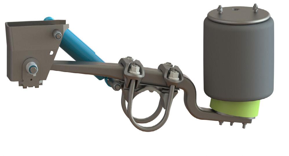
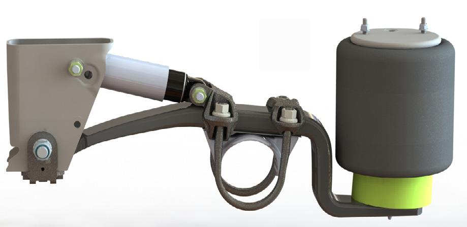
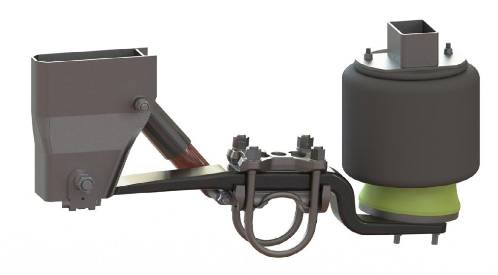
9 2 Air suspension system MBS-V1 2.1 Safety instructions - Always observe the general safety instructions and regulations (see chapter 1). 2.2 Overview (exploded view also available on the VALX website: 011/012 Hanger bracket L / Hanger bracket R 020 Wear plate 050 Axle seat 060 Tail end MBS-100 / MBS Trailing arm 081 Silent bush 090 Stud M Bolt M Shock absorber fixation M Nut M Nut M Washer spherical M Washer spherical M Shockabsorber 130/131 Airspring Ø300 / Ø Bolt M Nut M Nut M Bolt M Washer M Pivot bolt M Nut M Spacer M Stud 230/231/232 Bolt (suitable with plastic bump) 233/234/235 Bolt (suitable with pedestal) 240 Washer M Nut M Zincplate 401/402/403 Plastic bump 404 KTL Bump plate 410 Pedestal WSM_
10 2.3 Periodic maintenance and inspection NOTE As road conditions may vary from one country to another, and specific use of the trailer axle may differ per haulier, the maintenance intervals given below are only indicative. The maintenance tables differentiate between on-road use (X) and off-road use (0). inspection item maintenance task see section maintenance interval every 3 months every 6 months every year every 3 years every 5 years all parts of the air suspension system air springs all bolted connections are - 0 X maintenance free in on-road conditions, but should be checked for rust-traces and movement regularly. cracks in the paint of bolt connections are a sign of movement. Service technicians must check these bolt connections and, if necessary, retighten using the stated torques. - 0 X check for damage, wear or incorrect X seating check correct fastening X shock absorbers check for leakage (light oil sweating X is allowed) air valves check general condition + leakage - 0 X axle clamping nuts check correct fastening pivot bolt check correct fastening bump stops check correct fastening X 10 WSM_
 Air spring (top)")
 M12 19 66 Nm (+0/-16) Check 40 Nm")
11 2.3.1 Check the air springs Torques item size width across flats torque (Nm) Air spring (top) M (+10/-0) Check 30 Nm Air spring (bottom) M Nm (+0/-16) Check 40 Nm WSM_

 M16 24 170 Nm (+17/-0) + 270 (+17/-13)")

12 2.3.2 Check the shock absorbers and mounting Light oil sweating is allowed. Oil leakage is not allowed. Ensure the nuts are facing outwards Make sure the text bottom or road on the shockabsorbers is facing down Torque at ride height Torques item size width across flats torque (Nm) shock absorber (top) M20 24 & Nm (+ 50 Nm - 0 Nm) Check 450 Nm shock absorber (bottom) M Nm (+17/-0) (+17/-13) Check 300 Nm Check the axle clamping nuts Torques item size width across flats torque (Nm) axle clamping (front) M Nm (+50/0) 1,2 Check 650 Nm axle clamping (rear) M Nm (+50/-0) 1,2 Check 750 Nm 1 When loosening the axle clamping, all fasteners need to be replaced! 2 First tighten the M24 connection of the axle claming, then tighten the M27 connection 12 WSM_
 2.3.")
13 2.3.4 Check the pivot bolt Torques item size width across flats torque (Nm) pivot bolt M Nm (+50/0) + apply grease on min. 90 of the thread surface + ring 1 Check 750 Nm 1 Grease specification: Lithium complex grease (class 2) Check the bump stop Torques item size width across flats torque (Nm) Plastic bump fastening (MBS-100) M (+10/-0) Check 30 Nm Steel bump fastening (MBS-200) M (+0/-16) Check 40 Nm MBS100 MBS200 MBS100 MBS200 WSM_
 M27 41 750 Nm 950 Nm (+50/-0) 3 3 shockabsorber (top) M20 24 & 30 450 Nm 550 Nm (+50/0) 1 4 axle clamp (front) M24 36 650 Nm 800 Nm (+50/0) 3 5 pivot bolt M27 41 750 Nm 950 Nm (+50/0) + apply")
 66 (+0/-16) 9 bolted bracket M16 24 300 Nm 170 Nm (+17/-0) + 270 (+17/-13) 1 Torque at ride height 2 Grease specification: Lithium complex grease (class 2) 3 First tighten")
14 2.3.6 Air suspension system torques overview Torques item size width across flats inspection when replacing 1 shockabsorber (bottom ) M Nm 170 Nm (+17/-0) (+17/-13) 1 2 axle clamp (rear) M Nm 950 Nm (+50/-0) 3 3 shockabsorber (top) M20 24 & Nm 550 Nm (+50/0) 1 4 axle clamp (front) M Nm 800 Nm (+50/0) 3 5 pivot bolt M Nm 950 Nm (+50/0) + apply grease min 90 of the thread surface + ring 1,2 6 air spring (bottom) M Nm 66 Nm (+0/-16) 7 air spring (top) M Nm 30 (+10/-0) 8 plastic bump fastening steel bump fastening M12 M Nm 40 Nm 30 (+10/-0) 66 (+0/-16) 9 bolted bracket M Nm 170 Nm (+17/-0) (+17/-13) 1 Torque at ride height 2 Grease specification: Lithium complex grease (class 2) 3 First tighten the M24 connection of the axle clamping, then tighten the M27 connection 14 WSM_


15 2.4 Disassembly, assembly and adjustments Replace the shock absorber Work safely. Make sure that the axle is adequately supported. Make sure the text bottom or road and yellow sticker on the shockabsorbers are facing down WSM_

 M20 24 & 30 550 Nm (+ 50 Nm - 0 Nm) Check 450 Nm shockabsorber (bottom) M16 24 170 Nm (+17/-0) +")
16 2.4.1 Replace the shock absorber (continued) Bolt shock absorber from inside to outside. Check for correct torque, and use the correct hole for MBS-100 or MBS-200. Torque bolt connections at ride height Torques item size width across flats torque (Nm) shockabsorber (top) M20 24 & Nm (+ 50 Nm - 0 Nm) Check 450 Nm shockabsorber (bottom) M Nm (+17/-0) (+17/-13) Check 300 Nm 16 WSM_


17 2.4.2 Replace the air springs Disconnect the air line before replacement. Work safely. Make sure that the axle is adequately supported. Make sure the treaded end is completely inserted into the air spring bottom piece. WSM_
 air spring (bottom) M12 19 66 Nm (+0/-16) Check 40 Nm air spring (top) M12 (2x) 19 30 Nm (+ 10/-0) Check 30 Nm 18")
18 2.4.2 Replace the air springs (continued) Make sure that the shape of the airspring is placed correctly on the tail end (step 5) After replacement reconnect the air line. Torques item size width across flats torque (Nm) air spring (bottom) M Nm (+0/-16) Check 40 Nm air spring (top) M12 (2x) Nm (+ 10/-0) Check 30 Nm 18 WSM_
 shockabsorber (bottom) M16 24 170 Nm (+17/-0)")
19 2.4.3 Replace complete air suspension Work safely. Make sure that the axle is adequately supported. Bolt shock absorber from inside to outside. Make sure the text bottom or road and yellow sticker on the shockabsorbers are facing down Torques item size width across flats torque (Nm) shockabsorber (bottom) M Nm (+17/-0) (+17/-13) Check 300 Nm WSM_

 in the")
 axle clamp (rear) M27 41 950 Nm (+50/-0) Check 750 Nm 20")
20 2.4.3 Replace complete air suspension (continued) Make sure that the axle seat is well placed in the axle groove Make sure the zinc plate is well placed between the trailing arm and axle beam Always tighten the M24 nuts before tightening nut M27 Recheck the spring track Torques item size width across flats torque (Nm) axle clamp (front) M Nm (+50/-0) Check 650 Nm Check the correct tail end off set Place the M27 bolt in the trailing arm with the flat faces (see bolt head) in the length of the trailing arm Make sure the M24 connections are fully tightened before tightening the M27 connection Recheck the tail end offset Torques item size width across flats torque (Nm) axle clamp (rear) M Nm (+50/-0) Check 750 Nm 20 WSM_
 Pivot bolt M27 41 950 Nm (+50/-0)")
21 2.4.4 Assemble the pivot bolt Apply grease on min. 90 of the thread surface + ring Grease specification: Lithium complex grease (class 2). Before tightening to end torque, make sure the trailer is at correct driving height Torques item size width across flats torque (Nm) Pivot bolt M Nm (+50/-0) Check 750 Nm WSM_
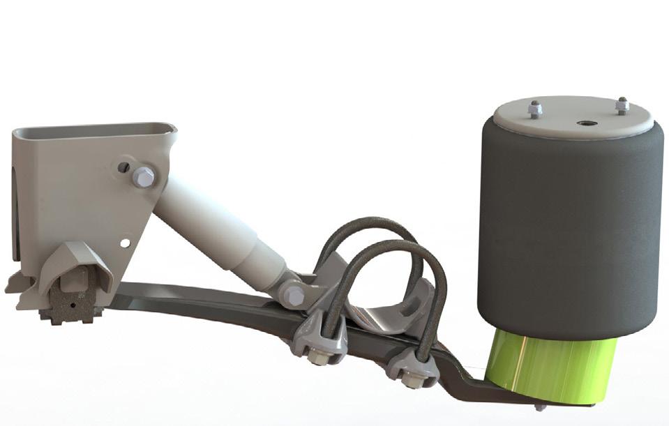
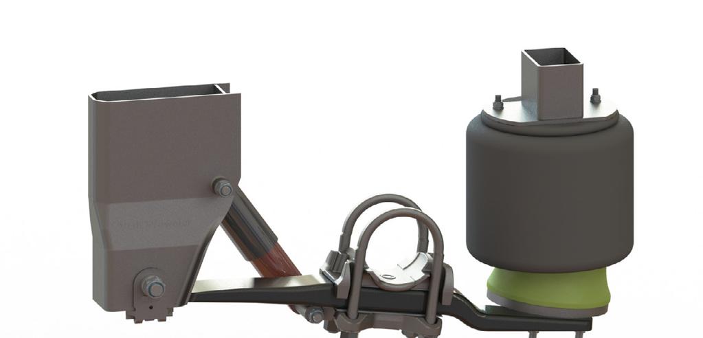
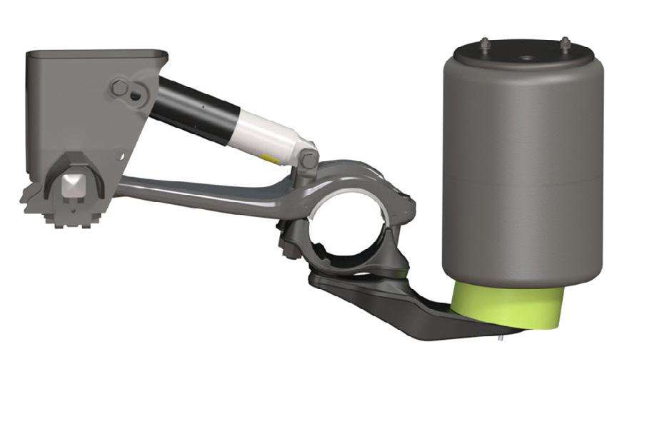
22 3 Air suspension system MBS-V2 3.1 Safety instructions - Always observe the general safety instructions and regulations (see chapter 1). 3.2 Overview - Exploded view also available on the VALX website: Hanger bracket 020 Wear plate 023 Brace weld (optional) 040 Dowel 051/052 Axle seat L / Axle seat R 060 U-bolt plate front / U-bolt plate back 080 Trailing arm 081 Silent bush 092 U-bolt 120 Shockabsorber 130/131 Airspring Ø300 / Ø Bolt M Nyloc nut M Bolt M Washer M Pivot bolt M Nyloc nut M Spacer M Stud M12 / Bolt M Bolt M Washer M Wheel nut / Axle clamping nut 250 Nyloc nut M Zincplate 300 Air spring offset plate V=20 / V= Air spring pedestal weld 22 WSM_
23 3.3 MBS-V2 code explanation - Code example and options: MBS-V (B) MBS-V2 Air suspension system 110 Defined specification / riding height range according VALX MBS-V2 Green book. Main series: (see overview on page 22) MBS-V2-100 MBS-V2-200 MBS-V Trailing arms 75 wide trailing arm 95 wide trailing arm 300 Air spring diameter Ø300 DJ6 air spring Ø335 DJ6 air spring Ø300 DJ8 air spring Ø335 DJ8 air spring 20 Air spring offset 20 offset in combination with Ø300 air spring 45 offset in combination with Ø335 air spring (-B) Optional casted bracing - Prescribed for trailers with rigid body (such as reefers, tankers, moving floor) 75 wide trailing arm - standard without casted bracing 95 wide trailing arm - standard with casted bracing WSM_
24 3.4 MBS-V2 air spring offset overview NOTE Depending on the trailing arm and air spring combination, defined offset plate is needed (V=20 or V=45). The overiew defines the top and bottom air spring offset dimensions, and air connection offset. 24 WSM_
25 3.5 Periodic maintenance and inspection NOTE As road conditions may vary from one country to another, and specific use of the trailer axle may differ per haulier, the maintenance intervals given below are only indicative. The maintenance tables differentiate between on-road use (X) and off-road use (0). inspection item maintenance task see section maintenance interval every 3 months every 6 months every year every 3 years every 5 years all parts of the air suspension system air springs and offset plates all bolted connections are - 0 X maintenance free in on-road conditions, but should be checked for rust-traces and movement regularly. cracks in the paint of bolt connections are a sign of movement. Service technicians must check these bolt connections and, if necessary, retighten using the stated torques. - 0 X check for damage, wear or incorrect X seating check correct fastening X shock absorbers check for leakage (light oil sweating X is allowed) air valves check general condition + leakage - 0 X axle clamping nuts check correct fastening pivot bolt check correct fastening WSM_
 M12 (2x) 19 30 (+10/-0) Check 30 Nm Air spring (bottom) M12 (1x) 19 66 Nm (+0/-16) Check 40 Nm Air spring support plate M12 (2x) 19 66 Nm")
 19 30 (+10/-0) Check 30 Nm Air spring (bottom) M12 (1x) Hex socket wrench 8 Air spring support plate M12 (2x) 19 66 Nm (+0/-16) Check 40 Nm 26")
26 3.5.1 Check the air springs and offset plate - Ø300 air spring, 20mm offset on 75 wide trailing arm Torques item size width across flats torque (Nm) Air spring (top) M12 (2x) (+10/-0) Check 30 Nm Air spring (bottom) M12 (1x) Nm (+0/-16) Check 40 Nm Air spring support plate M12 (2x) Nm (+0/-16) Check 40 Nm - Ø335 air spring, 45mm offset on 75 and 95 wide trailing arm Torques item size width across flats torque (Nm) Air spring (top) M12 (2x) (+10/-0) Check 30 Nm Air spring (bottom) M12 (1x) Hex socket wrench 8 Air spring support plate M12 (2x) Nm (+0/-16) Check 40 Nm 26 WSM_

 M12 (1x) 19 66 Nm (+0/-16) Check 40 Nm WSM_2052-01")
27 3.5.1 Check the air springs and offset plate (continued) - Ø300 and Ø335 air springs, 20mm offset on 95 wide trailing arm Torques item size width across flats torque (Nm) Air spring (top) M12 (2x) (+10/-0) Check 30 Nm Air spring (bottom) M12 (1x) Nm (+0/-16) Check 40 Nm WSM_

 M20 24 & 30 200 Nm (+ 20 Nm - 0 Nm) + 180 (+18 /-9 ) Check 55")
 axle clamping nuts M22 32 600 Nm")
28 3.5.2 Check the shock absorbers and mounting Light oil sweating is allowed. Oil leakage is not allowed. Ensure the nuts are facing outwards Make sure the text bottom or road on the shockabsorbers are facing down (noted on the sticker) Torque at ride height Torques item size width across flats torque (Nm) shock absorber (top + bottom) M20 24 & Nm (+ 20 Nm - 0 Nm) (+18 /-9 ) Check 550 Nm Check the axle clamping nuts Torques item size width across flats torque (Nm) axle clamping nuts M Nm (+25/0) 1,2 Check 600 Nm 1 When loosening the axle clamping, all fasteners need to be replaced! 2 Tighten the axle clamping nuts evenly and crosswise 28 WSM_
 WSM_2052-01 29")
29 3.5.4 Check the pivot bolt Torques item size width across flats torque (Nm) pivot bolt M Nm (+25/0) (+27 /-13 ) +apply grease on min. 90 of the thread surface + ring 1 Check 750 Nm 1 Grease specification: Lithium complex grease (class 2) WSM_
 3 pivot bolt M27 41 750 Nm 250 Nm (+25/0) + 250 (+27 /-13 ) + apply grease on min.")
30 3.5.5 Air suspension system torques overview Torques item size width across flats inspection when replacing 1 shockabsorber (top + bottom ) M20 24 & Nm 200 Nm (+20/-0) (+18/-9) 1 2 axle clamp M Nm 600 Nm (+25/-0) 3 pivot bolt M Nm 250 Nm (+25/0) (+27 /-13 ) + apply grease on min. 90 of the thread surface + ring 1,2 4 air spring (bottom) M Nm 66 Nm (+0/-16) 5 air spring (top) M Nm 30 (+10/-0) 6 air spring support plate M Nm 66 (+0/-16) 7 axle lift M Nm 200 Nm (+/-20) 1 Torque at ride height 2 Grease specification: Lithium complex grease (class 2) 30 WSM_


31 3.6 Disassembly, assembly and adjustments Replace the shock absorber Work safely. Make sure that the axle is adequately supported. Make sure the text bottom or road on the shockabsorbers are facing down (noted on the sticker) WSM_
 shockabsorber (top + bottom) M20 24 & 30 200 Nm (+ 20/-0) + 180 (+18")
32 3.6.1 Replace the shock absorber (continued) Bolt shock absorber from inside to outside. Check for correct torque table below. Torque bolt connections at ride height Torques item size width across flats torque (Nm) shockabsorber (top + bottom) M20 24 & Nm (+ 20/-0) (+18 /-9 ) Check 550 Nm 32 WSM_
 Disconnect the air")
33 Replace the air springs - Ø300, 20mm offset on 75 wide trailing arm (disassembly) Disconnect the air line before replacement. Work safely. Make sure that the axle is adequately supported. WSM_


34 Replace the air springs - Ø300, 20mm offset on 75 wide trailing arm (assembly) Make sure the threaded end is completely inserted into the air spring bottom piece (step 1) 34 WSM_
 Disconnect the")
35 Replace the air springs - Ø335, 45mm offset on 75 and 95 wide trailing arm (disassembly) Disconnect the air line before replacement. Work safely. Make sure that the axle is adequately supported. WSM_


36 Replace the air springs - Ø335, 45mm offset on 75 and 95 wide trailing arm (assembly) Make sure the hexagon bolt is tightened before placing the air spring and offset plate on the trailing arm 36 WSM_
 Disconnect the")
37 Replace the air springs - Ø300 / Ø335, 20mm offset on 95 wide trailing arm (disassembly) Disconnect the air line before replacement. Work safely. Make sure that the axle is adequately supported. WSM_

 Tighten the connections with")
38 Replace the air springs - Ø300 / Ø335, 20mm offset on 95 wide trailing arm (assembly) Tighten the connections with the correct torque setting 38 WSM_


39 3.6.3 Replace complete air suspension Make sure that the axle seat is well placed in the axle groove at the correct spring track The shock absorber tube must be positioned on the vehicle inside Make sure the zinc plate is well placed between the trailing arm and axle seat Place the dowel through the zinc plate and in the hole at the rear of the axle seat Place the trailing arm on the zinc plate, make sure the dowel falls in the hole in the trailing arm Pull the trailing arm to the front Place the U-bolt plates over the trailing arm Place the U-bolt plate with the long legs at the front and with the arrow pointing in the travel direction SPRING TRACK Place the U-bolts around the axle and through the U-bolt plates Tighten the wheelnuts slightly (hand tighten) until the u-bolts are positioned against the axle tube Check the sping track again by measuring the distance through the spring eyes Adjust the spring track to the correct track with a rubber hammer if necessary Tolerance spring track: +/- 2mm WSM_

40 3.6.3 Replace complete air suspension (continued) LEFT SIDE = RIGHT SIDE Check the distance between the trailing arm eye and the hubface on both sides of the axle The distance should be the same on both sides Adjust the alignment with a rubber hammer if necessary Tolerance alignment: LEFT = RIGHT +/- 2mm Tighten the U-bolts crossewise and evenly on both sides Check, after tightening, if the spring track and air spring alignment are within tolerance The thread lengths from the U-bolts must be evenly above the nuts Torque item size width across flats inspection when replacing 1 axle clamp M Nm 600 Nm (+25/-0) 40 WSM_
VALX Trailer axles. Trailer builder manual. MBS-V2 Range Air Suspension for grooved VALX axles. Document: TBM_ Date: Revision: 01
 VALX Trailer axles Trailer builder manual MBS-V2 Range Air Suspension for grooved VALX axles Document: Date: 03-2018 Revision: 01 Contact Details For additional information contact VALX Valx B.V. De Amert
W BW GW. Workshop manual. Mechanical suspensions BPW, series ECO Cargo W / BW / GW. BPW-WH-W-BW-GW e
 W BW GW Workshop manual Mechanical suspensions BPW, series ECO Cargo W / BW / GW BPW-WH-W-BW-GW 35251401e Page 2 BPW-WH-W-BW-GW 35251401e BPW-WH-W-BW-GW 35251401e Page 3 Contents 1. Product identification...
- December V1.4
 User guide TD steering system (00, 00 and 005) - December 05 - V.4 www.tridec.com Table of Contents Contents Preface... 3 Chapter : Safety & environmental consideration... 4 Symbols... 4 Safety regarding
4 TIER STOCKER SERVICE CART
 4 TIER STOCKER SERVICE CART 90160 ASSEMBLY AND OPERATING INSTRUCTIONS 3491 Mission Oaks Blvd., Camarillo, CA 93011 Visit our Web site at http://www.harborfreight.com Copyright 2003 by Harbor Freight Tools.
- September V1.1
 User guide TD-X steering system (0301) - September 2014 - V1.1 www.tridec.com Table of Contents Contents Preface... 3 Chapter 1: Safety & environmental consideration... 4 Symbols... 4 Safety regarding
EAC. Workshop manual. BPW air suspensions, series ECO Air COMPACT. BPW-WH-EAC e
 EAC Workshop manual BPW air suspensions, series ECO Air COMPACT BPW-WH-EAC 35161701e Page 2 BPW-WH-EAC 35161701e Valid: 01.01.2017 Subject to change without notice. Current versions and additional information
TMC LMV & LMXp series
 TMC LMV & LMXp series AIR SUSPENSION SERVICE MANUAL TMC Australia Pty Ltd Telephone: + 61 3 8786 3688 78 Star Crescent Facsimile: + 61 3 8786 3699 Hallam E-Mail: info@tmcaus.com.au Victoria 3803 Australia
BEARING ADAPTERS FWD/FRONT WHEEL. Model 45210
 BEARING ADAPTERS FWD/FRONT WHEEL Model 45210 Set up And Operating Instructions Diagrams within this manual may not be drawn proportionally. Due to continuing improvements, actual product may differ slightly
Assembly instructions PRORUNNER mk1 2
 Assembly instructions PRORUNNER mk1 Version 0.1 / 01-JUN-2013 Copyright Qimarox B.V. All rights reserved. No part of this document may be copied, stored in a database and/or published by means of printing,
WHEEL KIT FOR 13 HP GENERATOR
 WHEEL KIT FOR 13 HP GENERATOR 94192 ASSEMBLY AND OPERATING INSTRUCTIONS Due to continuing improvements, actual product may differ slightly from the product described herein. 3491 Mission Oaks Blvd., Camarillo,
Swing Back Trailer Jack
 Swing Back Trailer Jack Model: 91474 ASSEMBLY AND OPERATING INSTRUCTIONS Diagrams within this manual may not be drawn proportionally. Due to continuing improvements, actual product may differ slightly
RO Automatic trailer coupling. Repair instructions. 5KPVM02000 Towing Hitch Automatic Rockinger RO244A
 utomatic trailer coupling Repair instructions 5KPVM02000 Towing Hitch utomatic Rockinger RO244 5KPVM02010 Towing Hitch utomatic Rockinger foot operated RO244L Contents 1 General Validity and application
TMC 11T Air Suspension Service Manual
 TMC 11T Air Suspension Service Manual The Group Disclaimer Versioning The author and publisher have made their best efforts to prepare this manual, and the information contained in this manual is current
DISC BRAKE CALIPER TOOL SET
 DISC BRAKE CALIPER TOOL SET 40732 ASSEMBLY AND OPERATING INSTRUCTIONS Diagrams within this manual may not be drawn proportionally. Due to continuing improvements, actual product may differ slightly from
Version VDL Weweler b.v. Maintenance & Installation Manual
 Version 1.3 18-8-2014 VDL Weweler b.v. Maintenance & Installation Manual CONTENTS 1. Introduction 2 2. Maintenance work 3 - Overview - Air springs - Shock absorbers - U-Bolts - Pivot Bolts - Air spring
STEEL SIDE PANEL KIT. Model (FOR USE WITH MODEL FOLDABLE UTILITY TRAILER)
") STEEL SIDE PANEL KIT Model 47423 (FOR USE WITH MODEL 42709 FOLDABLE UTILITY TRAILER) Set up and Operating Instructions (MODEL 42709 TRAILER and TARP NOT INCLUDED. TARP SOLD SEPARATELY. Shown for illustration
STEEL SIDE PANEL KIT Model 47423 (FOR USE WITH MODEL 42709 FOLDABLE UTILITY TRAILER) Set up and Operating Instructions (MODEL 42709 TRAILER and TARP NOT INCLUDED. TARP SOLD SEPARATELY. Shown for illustration
OWNER S GUIDE 8A DURALIFT II 13,200 LB. CAPACITY. Link Mfg. Ltd th St. N.E. Sioux Center, IA USA
 OWNER S GUIDE 8A000715 DURALIFT II 13,200 LB. CAPACITY Link Mfg. Ltd. 223 15th St. N.E. Sioux Center, IA USA 51250-2120 www.linkmfg.com QUESTIONS? CALL CUSTOMER SERVICE 1-800-222-6283 DEALER / INSTALLER:
CAMBELT TENSION GAUGE
 CAMBELT TENSION GAUGE Model 96557 Operating Instructions Diagrams within this manual may not be drawn proportionally. Due to continuing improvements, actual product may differ slightly from the product
Bucket Grease Pump ASSEMBLY AND OPERATING INSTRUCTIONS
 Bucket Grease Pump 9793 ASSEMBLY AND OPERATING INSTRUCTIONS 349 Mission Oaks Blvd., Camarillo, CA 930 Visit our Web site at http://www.harborfreight.com Copyright 2004 by Harbor Freight Tools. All rights
MAINTENANCE INSTRUCTIONS VDL WEWELER HD & MBS-L/V/W/F AIR SUSPENSION SYSTEMS
 MAINTENANCE INSTRUCTIONS VDL WEWELER HD & MBS-L/V/W/F AIR SUSPENSION SYSTEMS DOCUMENT: DATE: 05-2017 REVISION: - Contact Details For additional information contact VDL Weweler b.v. P.O. Box 142, 7300 AC
INSTALLATION AND MAINTENANCE MANUAL
 IMPORTANT This manual must accompany the trailer when delivered to the end user. INSTALLATION AND MAINTENANCE MANUAL ISS Series Suspensions 347 King Street West, Ingersoll, Ontario, Canada, N5C 3K6 Ph:
MS2200, MS2500, and MS3000 Suspension Installation Manual ON/OFF HIGHWAY SUSPENSION SYSTEM
 MS22, MS25, and MS3 Suspension Installation Manual ON/OFF HIGHWAY SUSPENSION SYSTEM 972.547.62 8.445.736 FAX: 972.542.97 725 E. UNIVERSITY ST. McKINNEY, TEXAS 7569 www.watsonsuspensions.com Watson & Chalin
2 TONNE TROLLEY JACK
 2 TONNE TROLLEY JACK 61829 IMPORTANT: Please read these instructions carefully to ensure the safe and effective use of this product and save these instructions for future reference. This manual has been
JSK 34. Installation and operating instructions
 JSK 34 EN Installation and operating instructions Table of contents 1 Explanation of symbols... 3 2 Safety information... 4 2.1 Safety information for operation... 4 2.2 Safety information for installation...
2-1/4 Gallon Sprayer
 2-/4 Gallon Sprayer 94008 ASSEMBLY AND OPERATING INSTRUCTIONS 349 Mission Oaks Blvd., Camarillo, CA 930 Visit our Web site at http://www.harborfreight.com Copyright 2005 by Harbor Freight Tools. All rights
INSTALLATION INSTRUCTIONS
 INSTLLTION INSTRUCTIONS Before you begin installation, please read the following carefully: - The suspension components must match the suspensions application specifications (springs and shock/struts identification
2 GALLON COOLANT PUMP
 2 GALLON COOLANT PUMP Model 45333 ASSEMBLY AND OPERATING INSTRUCTIONS 3491 Mission Oaks Blvd., Camarillo, CA 93011 Visit our Web site at http://www.harborfreight.com Copyright 2001 by Harbor Freight Tools.
MINIATURE ALUMINUM JACK STANDS (1 PAIR) Model 90892
 Model 90892") MINIATURE ALUMINUM JACK STANDS (1 PAIR) Model 90892 ASSEMBLY and OPERATING INSTRUCTIONS 3491 Mission Oaks Blvd., Camarillo, CA 93011 Visit our Web site at http://www.harborfreight.com Copyright 2003 by
MINIATURE ALUMINUM JACK STANDS (1 PAIR) Model 90892 ASSEMBLY and OPERATING INSTRUCTIONS 3491 Mission Oaks Blvd., Camarillo, CA 93011 Visit our Web site at http://www.harborfreight.com Copyright 2003 by
WINDSHIELD REMOVAL KIT
 WINDSHIELD REMOVAL KIT 94180 ASSEMBLY AND OPERATING INSTRUCTIONS Due to continuing improvements, actual product may differ slightly from the product described herein. 3491 Mission Oaks Blvd., Camarillo,
APPLICATION GUIDE FOR: CAMSHAFT DRIVE CHAIN WEAR INDICATOR
 BRITISH MADE APPLICATION GUIDE FOR: CAMSHAFT DRIVE CHAIN WEAR INDICATOR 16239 This document is part of the product, keep it for the life of the product passing it on to any subsequent holder of the product.
TMC ARS AIR SUSPENSION
 TMC ARS AIR SUSPENSION SERVICE MANUAL TMC Axle Manufacturing Sdn. Bhd. Telephone: + (60) 3 6187 7788 79 & 81, Jalan 5/10B, Spring Crest Industrial Park, Facsimile: + (60) 3 6187 6722 68100 Batu Caves,
PROPANE TORCH WITH TURBO BURNER
 PROPANE TORCH WITH TURBO BURNER MODEL 91894 ASSEMBLY AND OPERATING INSTRUCTIONS 3491 Mission Oaks Blvd., Camarillo, CA 93011 Visit our Web site at http://www.harborfreight.com TO PREVENT SERIOUS INJURY,
4-VOLT LITHIUM-ION AUTO-LOAD SCREWDRIVER w/led WORKLIGHT
 SKU 241-1394 4-VOLT LITHIUM-ION AUTO-LOAD SCREWDRIVER w/led WORKLIGHT Operation Manual WARNING! Please read this manual before using this product. Failure to do so can result in serious injury. SAVE THIS
MOUNTABLE WALL SINK ASSEMBLY AND OPERATING INSTRUCTIONS
 MOUNTABLE WALL SINK 90326 ASSEMBLY AND OPERATING INSTRUCTIONS 3491 Mission Oaks Blvd., Camarillo, CA 93011 Visit our Web site at http://www.harborfreight.com Copyright 2003 by Harbor Freight Tools. All
Installation Instructions
 Instructions Created by an: Revised 7-11-17 LRT 2005-2017 3/1 Leveling/ Lift Kit for Toyota Tacoma by Low Range Off-Road (SKU# LR-LRTACO) Installation Instructions Suggested Tools: CAUTION: Safety glasses
INSTALLATION AND MAINTENANCE MANUAL. ROADTRACKtm RTD SUSPENSION
 INSTALLATION AND MAINTENANCE MANUAL ROADTRACKtm RTD SUSPENSION Roadtrack RTD Series Suspension The ROADTRACK series suspension system is a three point system available in undermount or underslung set-ups.
INSTALLATION INSTRUCTIONS
 INSTLLTION INSTRUCTIONS INSTLLTION INSTRUCTIONS Before you begin installation, please read the following carefully: - Ensure that the certificate matches the vehicle specifications (front vehicle identification
BELT GRINDER INSTRUCTION MANUAL READ CAREFULLY AND UNDERSTAND THESE INSTRUCTIONS BEFORE USE.
 www.industrialtool.com.au BELT GRINDER INSTRUCTION MANUAL READ CAREFULLY AND UNDERSTAND THESE INSTRUCTIONS BEFORE USE. LIMITED WARRANTY Industrial Tool & Machinery Sales (hereinafter refered to as ITMS)
UTILITY WAGON WITH 1000 LB. CAPACITY
 UTILITY WAGON WITH 1000 LB. CAPACITY 94908 ASSEMBLY & OPERATING INSTRUCTIONS Due to continuing improvement, actual product may differ slightly from the product described herein. 3491 Mission Oaks Blvd.,
INSTRUCTION MANUAL. Pacific Self-locking Beam Trolleys Pacific Adjustable Angle Clamps Pacific Top Girder Clamps
 INSTRUCTION MANUAL Pacific Self-locking Beam Trolleys Pacific Adjustable Angle Clamps Pacific Top Girder Clamps IMPORTANT Please read this instruction manual before using these products. This manual contains
The information in this instruction manual is subject to modifications without prior notice and is the exclusive property of Zorzini.
 Dear Customer, Thank you for choosing a Zorzini S.p.A. product. Zorzini manway doors and manhole covers 1 are designed and manufactured according to the highest standards in regards safety, functionality
Installation Instructions
 2003-Present Toyota 4Runner 2007-2014 FJ Cruiser LRT 3" Lift Kit by Low Range Off-Road (SKU# LR-LRFJ4RU) Installation Instructions Suggested Tools: CAUTION: Safety glasses should be worn at all times when
580RK SERVICE GUIDELINES For coupling models: 580 & 580J
 580 Coupling THE FIRST NAME IN QUALITY COUPLINGS 580RK SERVICE GUIDELINES For coupling models: 580 & 580J BEFORE GETTING STARTED: This procedure should only be performed by a qualified mechanic. Measure
INSTALLATION INSTRUCTIONS
 INSTALLATION INSTRUCTIONS FTL5207 1.5 FORD F-150 4WD 2 FT30612 SHOCK SPACER 1 FT30597 HARDWARE KIT 1 FT5207i INSTRUCTIONS 1 FTAS12 STICKER BLUE 10X4 DIE CUT 1 FTAS16 DRIVER WARNING DECAL 1 FTREGCARD REGISTRATION
User Manual Hoof trimmingcrush:sa0010. Version: User manual. Hoof trimming crush SA0010
 User Manual Hoof trimming crush SA0010 Manufacturer: Wopa Constructiebedrijf BV Rector Hulshofstraat 10 7135 JV Harreveld The Netherlands : +31-(0)544 372415 : +31-(0)544 372445 Email: info@wopa.com Website:
INSTALLATION INSTRUCTION 88581
 INSTALLATION INSTRUCTION 88581 FOR RANCHO SUSPENSION SYSTEM RS6581B: DODGE RAM READ ALL INSTRUCTIONS THOROUGHLY FROM START TO FINISH BEFORE BEGINNING INSTALLATION Rev C IMPORTANT NOTES! WARNING: This suspension
Bearing Race Service Kit
 0907 Safety Warning Read all instructions and safety warnings prior to operation. Failure to do so could result in equipment damage, personal injury or even death. CAUTION: USE REPLACEMENT PARTS AND ACCESSORIES
ZE ZE ZE. Simplex expanding wedge brake Assembly and Maintenance Instructions
 Simplex expanding wedge brake Assembly and Maintenance Instructions Simplex expanding wedge brake Assembly and Maintenance Instructions Edition 1 This publication is not subject to any update service.
3 TONNE TROLLEY JACK
 3 TONNE TROLLEY JACK 16407 These instructions accompanying the product are the original instructions. This document is part of the product, keep it for the life of the product passing it on to any subsequent
CONTACTS EGR VALVE TESTER 66248
 EGR VALVE TESTER 66248 These instructions accompanying the product are the original instructions. This document is part of the product, keep it for the life of the product passing it on to any subsequent
CONTACTS RELAY TESTER 66249
 RELAY TESTER 66249 These instructions accompanying the product are the original instructions. This document is part of the product, keep it for the life of the product passing it on to any subsequent holder
User manual Pipe notcher Type: AL 1-2E
 User manual Pipe notcher Type: AL 1-2E Page 1 of 27 Table of contents 1. Foreword... 4 1.1. Name of machine... 4 1.2. Warning... 4 1.3. Target group for each chapter... 4 1.4. Symbols... 4 1.5. Re-ordering
INSTALLATION INSTRUCTIONS
 INSTLLTION INSTRUCTIONS Before you begin installation, please read the following carefully: - The suspension components must match the suspensions application specifications (springs and shock/struts identification
HYDRAULIC SPRING COMPRESSOR SET
 HYDRAULIC SPRING COMPRESSOR SET Model 47890 ASSEMBLY and OPERATING INSTRUCTIONS 3491 Mission Oaks Blvd., Camarillo, CA 93011 Visit our Web site at http://www.harborfreight.com Copyright 2002 by Harbor
GM P/U, Blazer, Suburban, 1 Ton 4WD 4-6 Kits
 92114500 1973-87 GM P/U, 1973-91 Blazer, Suburban, 1 Ton 4WD 4-6 Kits Thank you for choosing Rough Country for all of your suspension needs. Rough Country recommends a certified technician installs this
Printed: Doc-Nr: PUB / / 000 / 00
 ORIGINAL OPERATING INSTRUCTIONS Hilti HTE-P 33 dispenser It is essential that the operating instructions are read before the tool is operated for the first time. Always keep these operating instructions
6 OFF ROAD LIGHT BAR
 6 OFF ROAD LIGHT BAR LOUD speaker Model 95953 Set up And Operating Instructions Diagrams within this manual may not be drawn proportionally. Due to continuing improvements, actual product may differ slightly
User Manual of Bagibike Electric Bicycles
 User Manual of Bagibike Electric Bicycles Model: Bagibike B16. http://www.bagibike.com Page 1 FOREWORD The following operation manual is a guide to assist you. This manual is not a complete document on
Heavy Duty U-Joint Service Kit
 Heavy Duty U-Joint Service Kit 00 Safety Warning Read all instructions and safety warnings prior to operation. Failure to do so could result in equipment damage, personal injury or even death. CAUTION
Trailer Jack. Model Assembly and Operating Instructions
 Trailer Jack Model 37792 Assembly and Operating Instructions 3491 Mission Oaks Blvd., Camarillo, CA 93011 Copyright 1998 by Harbor Freight Tools. All rights reserved. No portion of this manual or any artwork
Propane torch. Model Assembly And Operation Instructions
 Propane torch Model 39953 Assembly And Operation Instructions Due to continuing improvements, actual product may differ slightly from the product described herein. 3491 Mission Oaks Blvd., Camarillo, CA
»Product» Safety Warning
 J1320 Installation Instructions 2018 Jeep Wrangler JL 3" Suspension Lift Read and understand all instructions and warnings prior to installation of product and operation of vehicle. Zone Offroad Products
INSTALLATION INSTRUCTION 88051
 INSTALLATION INSTRUCTION 88051 For Rancho Suspension System RS6551: Chevrolet 2500 Suburban & 2500 Avalanche READ ALL INSTRUCTIONS THOROUGHLY FROM START TO FINISH BEFORE BEGINNING INSTALLATION Rev C IMPORTANT
ASSEMBLY and OPERATING INSTRUCTIONS Mission Oaks Blvd. / Camarillo, CA 93011
 SPARK PLUG CLEANER ASSEMBLY and OPERATING INSTRUCTIONS 3491 Mission Oaks Blvd. / Camarillo, CA 93011 Copyright 1997 by Harbor Freight Tools. All rights reserved. No portion of this manual or any artwork
DWHOIST. Drywall Hoist Assembly & Operating Instructions
 DWHOIST Drywall Hoist Assembly & Operating Instructions READ ALL INSTRUCTIONS AND WARNINGS BEFORE USING THIS PRODUCT. SAVE THESE INSTRUCTIONS FOR FUTURE REFERENCE. This manual provides important information
1250 LB. CAPACITY MECHANICAL WHEEL DOLLY
 1250 LB. CAPACITY MECHANICAL WHEEL DOLLY 67287 SET-UP AND OPERATING INSTRUCTIONS Visit our website at: http://www.harborfreight.com Read this material before using this product. Failure to do so can result
INSTALLATION INSTRUCTIONS Mopar Performance 2 Lift System 2009 and Newer Dodge Ram 1500 (DS) 4WD PART NUMBER P
 4WD PART NUMBER P") INTRODUCTION Installation requires a professional mechanic. Prior to beginning, inspect the vehicle s steering, driveline, and brake systems, paying close attention to the suspension link arms and bushings,
INTRODUCTION Installation requires a professional mechanic. Prior to beginning, inspect the vehicle s steering, driveline, and brake systems, paying close attention to the suspension link arms and bushings,
Tensioning Winder 30. CS9160 Eco Solvent Printers
 Tensioning Winder 30 User s Guide For Océ CS9050, CS9060 & CS9160 Eco Solvent Printers This page is left blank intentionally 2 AP-40104 - Revision 1.2 20/06/2008 COPYRIGHT NOTICE COPYRIGHT 2008 Océ-Technologies
Cyclone High Speed Centering Shaft
 TIDLAND WINDING SOLUTIONS Cyclone High Speed Centering Shaft User Manual EN MI 270013883 1 CONTENTS INTRODUCTION 1-1 About these operating instructions... 1-1 SAFETY INFORMATION 2-1 Proper use... 2-2
AIRTEK for Volvo Vehicles Single to Dual Height Control Valve Conversion Kit
 Single to Dual Height Control Valve Conversion Kit SUBJECT: 60961-101 and 60961-102 LIT NO: 59310-026 DATE: January 2006 REVISION: A INTRODUCTION Prior to March 2005, some Volvo vehicle configurations
INSTALLATION INSTRUCTION 88146
 INSTALLATION INSTRUCTION 88146 Rev H FOR RANCHO SUSPENSION SYSTEM RS6547: 4WD SUBURBAN/YUKON XL, 4WD TAHOE/YUKON, & 4WD AVALANCHE READ ALL INSTRUCTIONS THOROUGHLY FROM START TO FINISH BEFORE BEGINNING
Technical Support Line: (952) Hanover Ave. Lakeville, MN
 Hanover Ave. Lakeville, MN") Technical Support Line: (952) 985-5675 Email: Sales@QA1.net 21730 Hanover Ave. Lakeville, MN 55044 www.qa1.net INSTALLATION INSTRUCTIONS QA1 1967-1979 Mopar A-Body Rear 6 link Conversion System QA1 p/n
Technical Support Line: (952) 985-5675 Email: Sales@QA1.net 21730 Hanover Ave. Lakeville, MN 55044 www.qa1.net INSTALLATION INSTRUCTIONS QA1 1967-1979 Mopar A-Body Rear 6 link Conversion System QA1 p/n
TOYOTA PRADO 150 Series Suspension Installation Instructions. NOTE: Occupational Health & Safety procedures must be observed at all times.
 INSTALLATION GUIDE TOYOTA PRADO 150 Series 2009+ Suspension Installation Instructions NOTE: Occupational Health & Safety procedures must be observed at all times. IMPORTANT: Installations should only be
Assembly and Maintenance Manual Type ASNU
 Assembly and Maintenance Manual Type ASNU Hatschekstr.36 69126 Heidelberg Germany Tel +49(0)6221 30470 Fax +49(0)6221 304731 info@stieber.de www.stieber.de Date of issue: 30.05.2018 GB Revision: 0 U:\EngUsers\!ProduktDoku\1AAA_Einbauerklaerung_Wartungsanleitung_Konformitaetserklaerung\1AAA_Wartungsanleitungen\Orginal_Worddatei\_ASNU.docx
Installation Guide 2016 Kawasaki ZX10-R Exhaust Kit
 Installation Guide 2016 Kawasaki ZX10-R Exhaust Kit!! THIS PRODUCT IS DESIGNED FOR USE IN CLOSED COURSE RACING AND IS NOT INTENDED FOR HIGHWAY USE!! Congratulations on the purchase of your new TaylorMade
Installation and Operating Manual for Tank and Equipment Cleaning Nozzles Series 5TM
 Installation and Operating Manual for Tank and Equipment Cleaning Nozzles Series 5TM 150 150 150 This instruction manual contains proprietary information which is protected by copyright laws. No part of
Wallace Tri-Adjustable Gantry Cranes Square Tube Assembly Instructions
 Wallace Tri-Adjustable Gantry Cranes Square Tube Assembly Instructions For any additional information, Please call 1- S 1. Read and understand instructions before using this gantry. 2. Inspect gantry thoroughly
TIMING KIT APPLICATION GUIDE FOR: ENGINE
 BRITISH MADE APPLICATION GUIDE FOR: ENGINE TIMING KIT 27021 This document is part of the product, keep it for the life of the product passing it on to any subsequent holder of the product. Read all information
INSTALLATION INSTRUCTIONS
 INSTALLATION INSTRUCTIONS 2017-2018 FORD F-250/F-350 SUPERDUTY TRACTION BAR KIT 12 BOLT REAR END VEHICLES ONLY FTS62008 Fabtech Motorsports 4331 Eucalyptus Ave. Chino, CA 91710 Tech Line: 909-597-7800
Installation Instructions
 Instructions Created by an: 2007-Present Toyota Tundra LRT Leveling Lift Kit - 4WD by Low Range Off-Road (SKU# LR-LRTundra) Instructions also apply to 2WD Kits. Installation Instructions Revised 7-11-17
INSTRUCTION MANUAL ANGLE GRINDER PT W
 INSTRUCTION MANUAL ANGLE GRINDER PT50360 4½ INCHES 120V 60Hz 600W 5A 12,000 rpm C US Note : Before operating this tool, read this manual and follow all safety rules and operating instructions. This electric
SEALER-15-1/2 ELECTRICAL IMPULSE
 SEALER-5-/ ELECTRICAL IMPULSE OPERATING INSTRUCTIONS 39 Mission Oaks Blvd., Camarillo, CA 930 Visit our Web site at http://www.harborfreight.com Copyright 000 by Harbor Freight Tools. All rights reserved.
KI AIR SUSPENSION (wide Pivot Bush)
") KI AIR SUSPENSION (wide Pivot Bush) Contents 1. Pre-assembly Considerations 2. Welding Instructions Chassis Connection 3. Tightening Instruction 4. Axle Alignment 5. Maintenance www.khitch.com.au Uncontrolled
KI AIR SUSPENSION (wide Pivot Bush) Contents 1. Pre-assembly Considerations 2. Welding Instructions Chassis Connection 3. Tightening Instruction 4. Axle Alignment 5. Maintenance www.khitch.com.au Uncontrolled
Assembly and Maintenance Manual Type AS
 Assembly and Maintenance Manual Type AS Hatschekstr.36 69126 Heidelberg Germany Tel +49(0)6221 30470 Fax +49(0)6221 304731 info@stieber.de www.stieber.de Date of issue: 30.05.2018 GB Revision: 0 U:\EngUsers\!ProduktDoku\1AAA_Einbauerklaerung_Wartungsanleitung_Konformitaetserklaerung\1AAA_Wartungsanleitungen\Orginal_Worddatei\_AS.docx
INSTALLATION AND MAINTENANCE MANUAL E6100 SERIES SPRING SUSPENSION
 INSTALLATION AND MAINTENANCE MANUAL E6100 SERIES SPRING SUSPENSION E6100 Series Spring Suspension The E6100 series suspension system is a three point system available in undermount or underslung set-ups.
Saf-Tite Coupling
 MANUFACTURING CO. THE FIRST NAME IN QUALITY COUPLINGS Installation, Inspection, Operation & Maintenance Guide Raising the Bar SAF TITE Strength & Value Saf-Tite 100-3 Coupling IMPORTANT Read these instructions
CHEVY / GMC 1500HD / 2500HD 2WD 8 LUG 7 BASIC KIT
 85101 2000-2010 CHEVY / GMC 1500HD / 2500HD 2WD 8 LUG 7 BASIC KIT C8510-4 MAIN BOX KIT W/ HARDWARE 1) FRONT X MEMBER 1) REAR X MEMBER 2) TORSION BAR DROPS 1) LEFT BUMP STOP 1) RIGHT BUMP STOP 2) SWAY BAR
25 GALLON PORTABLE OIL LIFT
 25 GALLON PORTABLE OIL LIFT Model 92859 SET UP AND OPERATING INSTRUCTIONS Diagrams within this manual may not be drawn proportionally. Due to continuing improvements, actual product may differ slightly
WR 22SE WR 25SE WR25SE. Handling instructions
 WR 22SE WR 25SE WR25SE Handling instructions GENERAL POWER TOOL SAFETY WARNINGS WARNING Read all safety warnings and all instructions. Failure to follow the warnings and instructions may result in electric
Installation Instructions READ THOROUGHLY BEFORE BEGINNING Signature Series Rail Kit Dodge Ram Trucks-all, including Mega-cabs
 INDEX Failure to follow all of these instructions may result in death or serious injury!. GUIDELINES FOR MATCHING TOW VEHICLE AND TRAILER. Pages -. DRILLED AND BOLTED INSTALLATION FIGURE. Page 4. NO-DRILL,
97-06 JEEP TJ/LJ LONG ARM UPGRADE KIT
 921663U00 97-06 JEEP TJ/LJ LONG ARM UPGRADE KIT Thank you for choosing Rough Country for your suspension needs. This kit is an upgrade kit only. This kit includes frame mounting points and adjustable long
(800) MON-FRI 7AM-5PM PST OR WEBSITE: ReadyLIFT.COM **Please retain this document in your vehicle at all times**
 MON-FRI 7AM-5PM PST OR WEBSITE: ReadyLIFT.COM **Please retain this document in your vehicle at all times**") IF YOUR ReadyLIFT PRODUCT IS MISSING A OR HAS A DAM- AGED PART, PLEASE CONTACT CUSTOMER SERVICE DIRECTLY. For warranty issues please return to the place of installation and contact ReadyLIFT. A NEW REPLACEMENT
IF YOUR ReadyLIFT PRODUCT IS MISSING A OR HAS A DAM- AGED PART, PLEASE CONTACT CUSTOMER SERVICE DIRECTLY. For warranty issues please return to the place of installation and contact ReadyLIFT. A NEW REPLACEMENT
AIRTEK for Mack Vehicles Single to Dual Height Control Valve Conversion Kit
 Single to Dual Height Control Valve Conversion Kit SUBJECT: Kit Nos.60961-128 and 60961-129 LIT NO: 59310-030 DATE: April 2006 REVISION: A INTRODUCTION As of March 2006 all of Mack vehicles will be equipped
Predelivery Instructions
 PINK Predelivery Instructions SR5030 Split-Row Planter Manufacturing, Inc. P.O. Box 5060 Salina, Kansas 67402-5060! Read this manual entirely. When you see this symbol, the subsequent instructions and
INSTALLATION INSTRUCTIONS
 INSTALLATION INSTRUCTIONS FTS24183 3 TRAIL BOX KIT 1 FT50294 JK PITMAN ARM 2 FT50261BK FRONT SWAY BAR END LINK 1 FT50533 HARDWARE SUBASSEMBLY 2 FT50492 FRONT BUMP STOP SPACER 2 FT50401BK REAR BUMP STOP
»Product» Safety Warning
 J1457, J1458 Installation Instructions 1984-2001 Jeep Cherokee XJ 4.5 Suspension Lift Read and understand all instructions and warnings prior to installation of product and operation of vehicle. Zone Offroad
AERO AIR TIRE PEDAL CAR. Assembly Instructions Model # USA. Tools Required: Recommended for children up to 200 lbs, ages 5-9
 AERO AIR TIRE PEDAL CAR Assembly Instructions Model # 998-700 USA Printed on 00% recycled paper! Recommended for children up to 200 lbs, ages 5-9 Tools Required: (pliers) (phillips head screwdriver) AERO
800 LB ATV DOLLY OWNER S MANUAL
 800 LB ATV DOLLY OWNER S MANUAL WARNING: Carefully read and understand all ASSEMBLY AND OPERATION INSTRUCTIONS before operating. Failure to follow the safety rules and other basic safety precautions may
INSTALLATION INSTRUCTIONS
 INSTALLATION INSTRUCTIONS FTL5108 2 2015 CHEVY COLORADO 4WD 2 FT20696 COLORADO SHOCK SPACER 1 FT30597 HARDWARE KIT 1 FT5108i INSTRUCTIONS 1 FTAS12 STICKER BLUE 10X4 DIE CUT 1 FTAS16 DRIVER WARNING DECAL
»Product» Safety Warning
 D2201 Installation Instructions 2012-2014 Dodge Ram 1500 4WD 2" Adventure Series Suspension System Read and understand all instructions and warnings prior to installation of product and operation of vehicle.