INSTALLATION AND MAINTENANCE MANUAL E6100 SERIES SPRING SUSPENSION
|
|
|
- Amie Parrish
- 5 years ago
- Views:
Transcription

1 INSTALLATION AND MAINTENANCE MANUAL E6100 SERIES SPRING SUSPENSION
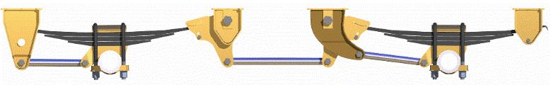
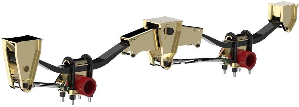
2 E6100 Series Spring Suspension The E6100 series suspension system is a three point system available in undermount or underslung set-ups. Single piece equalizers combined with axle seats of various heights lets you custom build your system to match your mounting height requirements. Axle spreads from 44 [1118mm] to 72 [1829mm] are available. All components are formed and fabricated from high quality steel and robotically welded for guaranteed precision and quality. Standard features include the Eveley "Long-Life" metalastic bushings at all pivot connections and large hanger footprint bases. This light-weight heavy duty suspension system is an excellent choice for continuously loaded equipment and offers high stability, low cost, long life and easy installation. An O.E.M. standard for all applications, available as single, tandem, tri-axle or multi-axle units. Superior Performance for the Industry Safety and durability go a long way with this Industry Standard design to give you the kind of superior performance that you've come to expect. Progressive Manufacturing Procedures Using today's "state of the art" manufacturing technologies in Robotics, Micro-electronics and Computers (CAD/CAM), an Eveley suspension has the quality and accuracy from start to finish. The direction here at Eveley is towards better design and manufacturing methods to ensure increased product life, safety and performance. Variable Axle Spacing Axle spacing of 44 [1118], 49" [1245mm], 54" [1372mm], 60" [1524mm] and 72"[1829mm] are available in single, tandem, or multi-axle configurations. Available in undermount and underslung configurations. Axle seat heights of 1 [25mm], 2" [51mm], 3" [76mm] allow a more customized ride height using the same springs. Components that "Go the Distance" High Strength steel used in all hangers and axle connections contribute to the unmatched durability. All pivot points feature high-tech "Long-Life" bushings. All U-bolts are Grade 8 material, and are reverse mounted and roll threaded to allow easy torquing to 700 ft lbs [949J]. 4/15/ pg. 2
3 UNDERMOUNT SUSPENSION Undermount spring suspensions (axle below spring configuration) use 7/8 U-bolts to connect the axle to the suspension for a positive fit. All U-bolts are grade eight material with rolled threads. With the use of the right U-bolt on your underslung suspension, you will experience less maintenance and a safer axle connection. STANDARD AXLE SPACINGS AVAILABLE 44 (1118mm) 49 (1245mm) 54 (1372mm) 60 (524mm) 72 (1829mm) UNDERSLUNG SUSPENSION Underslung spring suspension (axle on top of spring configuration) use 1 forged top U-bolts to connect the axle to the suspension for a positive fit. All U-bolts are grade eight material with rolled threads. With the use of the right U-bolt on your underslung suspension, you will experience less maintenance and a safer axle connection. STANDARD AXLE SPACINGS AVAILABLE 49 (1245mm) 54 (1372mm) 60 (524mm) 72 (1829mm) 4/15/ pg. 3
4 4 3/8" [111mm] E612A49UM UNDERMOUNT 94.5"[2400mm] 44" [1118mm] 42 3/4" [1086mm] 19 1/4" [489mm] 49 1/2" [1257mm] 18" [457mm] 8 3/4" [222mm] 24 3/4" [629mm] 24 3/4" [629mm] 3.38[86mm] 4/15/ pg. 4
5 Eveley International Corp. E612A54UM UNDERMOUNT 4/15/ pg. 5
6 Eveley International Corp. E612A60UM UNDERMOUNT 4/15/ pg. 6

7 E612A72UM UNDERMOUNT 4/15/ pg. 7
8 E6100 SERIES ORDERING INFORMATION In order to avoid confusion, our suspension kit numbering system is simple and easy to use. It contains all necessary information to identify all aspects of the kit requirements. Example: Therefore: A model designated as E613A60UM 15-1/2 TRA1150, is described as a Triaxle suspension from our 6100 Series of suspensions, that spaces the axles at 60"[1524mm] apart and mounts under the main frame rails (UMundermount) at a ride height of 15 1/2 [394mm], using TRA1150 springs. To determine the capacity and ride height you wish your trailer to operate at, we suggest that you refer to the spring selection charts on page 90. Please note that all of our models of suspensions can use any of the three (3) axle seats, 1"[25mm] to 3" [76mm] high, that we manufacture, thereby ensuring that a full range of ride heights that are common to the industry as well as many special ride heights may be achieved using the same spring. IMPORTANT!!! We do not recommend the use of High Arch springs with our E4400 Series tandem and tri-axle models. If added mounting height is required, we suggest the use of one of three axle seats plus the use of our extended hangers. Before specifying the springs to be used, we suggest that you consult the spring selection chart on page 5 of this publication. This gives you the mounting heights available with each type of spring. 4/15/ pg. 8

9 SPRING AND RIDE HEIGHT CHART SYMETRICAL SPRINGS 4/15/ pg. 9
10 E612A49US UNDERSLUNG 4/15/ pg. 10
11 E612A54US UNDERSLUNG 4/15/ pg. 11
12 E612A60US UNDERSLUNG 4/15/ pg. 12
13 E612A72US UNDERSLUNG 4/15/ pg. 13

14 UNDERSLUNG SPRING AND RIDE HEIGHT CHART INSTALLATION PROCEDURES E6100 INSTALLATION INSTRUCTIONS Major components of the suspensions are factory assembled by Eveley to help reduce your assembly time and also to ensure the correct fitting of all parts. FRAME ASSEMBLY 1. Take your measurements from the center of the King Pin position to the rear hanger and tack weld to the trailer frame. 2. Position the remaining hangers using the dimensions shown in the assembly drawings. 3. When all hangers are tacked to the frame, check for correct measurements and squareness to the frame. 4. For final welding instructions refer to Welding Specifications. AXLE ASSEMBLY 1. Position axle so that the brake cam rotation is the same as wheel rotation. Place axle seats on axle so they are horizontal to the axle and parallel to each other. Center to center width measurements of axle seats and hangers must be identical. 2. Tack weld into position, check for squareness and weld as per Welding Specifications. See Axle seat figure 3 -Page 17 4/15/ pg. 14
15 SUB ASSEMBLY 1. Next attach adjustable torque rods to curbside and rigid torque rods to roadside. Insert torque rod bolts so that washers and lock nuts are to the outside. At this stage do not tighten nuts. 2. Install springs, top plates and U-bolts. Line up springs so that distances between the diagonals and the ends are the same. Tighten U-bolt nuts to 700 Ft.lb [949.1 N/m] of torque and torque rod clamp bolts to 90 Ft.lb. [122.0 N/m] of torque. FINAL ASSEMBLY 1. Fit two sub-assemblies together, making sure the lipped end of each spring is located in the equalizer. (With the exception of wide spread where the rear spring assembly can be reversed if required.) 2. Insert spring rebound bolts in equalizer so that 1/2" nuts are to the outside of the trailer. These bolts should only be tightened enough to keep the bolt snug, but loose enough for the bolt to roll if engaged by the spring lip. On the E44 application, no bolt is fitted into the rear equalizer assembly. However, a spring rebound rod should be welded into the position where the bolt would normally be fitted. 3. Connect torque rods to front and center hangers. Tighten all torque rod bolts to 320 Ft.lb. [433.9 N/m]. 4/15/ pg. 15
16 ALIGNMENT AND ADJUSTMENT 1. Make sure the suspension is not binding at any point and that the trailer is resting level. 2. Commence suspension alignment by measuring from center of King Pin to the end centers of the front axle, when completed, measure from front axle centers to second axle centers and so on, depending on the axle configuration. Make sure suspension is in its neutral position. 3. Tighten torque rod clamp nuts to 90 Ft.lb. [122.0 N/m] of torque. 4. Align rear axle to front axle by measuring from the axle centers on each side and shorten or lengthen the adjustable torque arm screw on the rear axle until the measurements are the same. 5. IMPORTANT - Do not lubricate any parts of the suspension or apply grease to the ends of the springs. TRI-AXLE SPREADS Because of the extended length of these suspensions, the relationship between the fifth wheel coupler height and the mounting height of the suspension is very important. When units are designed around a wide-spread triaxle suspension, the designer, should ensure that when coupled to the tractor, the trailer suspension rides in the neutral position. If the unit rides in a semi-equalized state, overloading of the axles will result. This can be corrected by the addition of a riser block to the appropriate axles. This problem could also be experienced on Wide-Spread tandem suspensions with a spread of more than 72" [1829mm] between axle centers. This can be corrected by the addition of a riser block to the first axle. In some cases, two different spring seat heights can be supplied to counteract this situation. Any questions or problems regarding the performance of these suspensions should be directed to this company. 4/15/ pg. 16
17 AXLE SEAT Remember to maintain a tight fit between the axle seat and the axle tube prior to welding. SUSPENSION INSPECTION It is recommended, that after the first 1,000 miles (1,609 km), operators should check all nuts for tightness and re-torque. Re-torquing is essential to the guarantee and ensures proper operation. All torquing should be periodically checked; at 10,000 miles [16,090 km], 30,000 miles [48,270 km], 50,000 miles [80450 km] etc. THIS INSPECTION IS ESSENTIAL Failure to maintain the specified torque on all nuts and bolts could result in excessive hanger wear, bolt wear, bushing failure, broken springs, tire wear, and the stripping of bolt threads. A periodic check by the operator will eliminate these problems. 4/15/ pg. 17
18 WELDING SPECIFICATIONS Any approved welding rod such as 7018 or the equivalent, can be used. A minimum 5/16 (8mm) fillet weld should be used for attachment of hangers to the frame and braces to the hangers Figure 1: Hangers on I-beam sub-frame (standard). Centers of I-beam and hangers are the same. Figure 2: Hangers on I-beam sub-frame (standard). Centers of I-beam and hangers are offset to each other Reinforcing and bracing are req d 4/15/ pg. 18
19 Eveley International Corp. On standard suspension designs for trailers and semi-trailers, all axle and brake moments as well as the biggest portion of the torsional stabilizing forces and a portion of the spring weight vertical forces pass through the front mounting brackets into the vehicle frame. Therefore, the trailer frame must be strengthend as well as the hangers braced. A vertical reinforcement must be placed between the upper and lower flanges and welded to the web of the trailer frame. An angled brace should be placed between the suspension hanger face and a cross member. As shown below. Placing a brace between left and right hanger faces is not recommended 4/15/ pg. 19
20 AXLE SEAT Brackets which wrap around the axle should touch the axle as shown in view A in figure 3. With this type of fit, loads on the bracket are transferred directly to the axle. If a gap exists between the axle and the bracket as shown in view B in Fig.3, these loads are transferred to the weld. This may overstress and crack the weld. The weld arc should not be started at the end of the bead. Instead, the electrode should be started away from the end of the bead and moved as shown in figure 5. Any craters which remain should be filled during this movement. In both cases, the intention of this guidance is to insure that the stress risers which occur when either start or stopping a weld are located away from the ends of the weld. Figure 4: Axle seat on 5 [127mm] diameter axle. When welding axle seat in position mig welding is preferred. Welding wire should be 7018 or equivalent and should be performed so that welding is done in a flat position. If this is not possible welding should be performed using the stick method 4/15/ pg. 20
21 BUMP OUT BLOCKS It is the practice of some manufacturers to install bump out blocks or dumping blocks above the rear axle or axles of a spring suspension. This is supposed to help the stability of the unit during a dumping operation. In most cases the bump out blocks are installed incorrectly, and actually restricts the movement of the suspension and spring under normal operation. This situation causes accelerated wear of the spring and spring hangers, and ultimately creates an early failure of these parts. If the correct spring assembly is chosen for this combination, together with the recommended suspension assembly, the bump out blocks are not required. The stability of the suspension assembly will withstand the dumping operation. Before installing a suspension for this type of application, the manufacturer should check with the suspension supplier (Eveley International Corp.) to ensure that the correct suspension and spring combination has been chosen. Eveley International will not guarantee the performance of its suspensions, or the serviceability of the parts of the suspension, if bump out blocks are installed as part of the suspension assembly. All statements and compliance with our standard warranty policies will be NULL AND VOID under such conditions. This statement applies to all Eveley International spring suspensions assemblies with the following series numbers. E6400 E6000 E4400 E6100 E6200 This includes undermount, underslung, straddle mount, and flange mount models 4/15/ pg. 21
22 EQUALIZATION OF SPREAD AXLE CONFIGURATION When using multi-axle suspensions with extended axle spacing s, the relationship between the fifth wheel coupler height and the mounting height of the suspension is very important. When designing around spread axle suspensions, the manufacturer should ensure that when coupled to the prime mover, and in a loaded condition, the suspension rides in a neutral position. If the suspension rides in a semi-equalized condition it could produce: a.) Overloading of axles. b.) Increased tire and brake wear. c.) Spring breakage. d.) Suspension damage. If the suspension is running in the semi-equalized condition, or if the trailer is designed to have a natural draft to the rear, i.e. Tankers, a Container Chassis, the suspension can be ordered with different axle seat heights for each axle. This will allow the suspension to run in the neutral condition even if the trailer slopes or drafts to the rear. On existing suspensions, this same condition can be attained with the use of riser blocks. The designer should make every attempt to taper the frame and leave the suspension with identical axle seats. Eveley International cannot be held responsible for a suspension not equalizing properly if different axle seats or riser blocks are used. This same condition can also apply to Air-Ride suspensions as well as spring suspensions. For example, on a 48ft [14.63m] trailer with a tri-axle spread suspension on the rear, if the trailer is built for a 49-1/2" [1257mm] coupler height, but is actually running at 52" [1321mm] coupler height, the suspension will have used all of its articulation travel, in the empty condition. In the loaded condition, it will be locked out under normal travel, and will produce excess loadings on the spring ends and spring pads of the suspension. In the case of an Air-Ride suspension, the air bags would be extended outside of their normal working range, which could lead to differential axle loadings and increased component wear. Also to be considered when setting the coupler height of the trailer, should be the compatibility of the truck and trailer suspensions. If the truck suspension is Air-Ride and the trailer is spring, the trailer suspension will automatically use some of its articulation when loaded; the truck however, would always be at its original height. If compatibility is required for various coupler heights, i.e. 50" [1270mm] - 52" [1321mm], then a mean dimension should be chosen for the trailer coupler height, i.e., 51" [1295mm]. This will allow for equalization on the trailer suspension, without constantly running with negative movement. If you require assistance to calculate suspension heights, or more information on suspension equalization, please contact our Customer Service Department. 4/15/ pg. 22
23 EVELEY INTERNATIONAL CORP. PRODUCT WARRANTY This warranty shall be limited to the original purchaser from the date of sale and covers all new components manufactured by Eveley International Corp. to be free of defects in material and workmanship, for one year (parts and labour) and up to five years (parts only) when installed, assembled, and maintained in accordance with Eveley International Corp. installation and maintenance procedures, under normal use and service. The product installer is responsible for providing correct vehicle components and attachments, and providing the clearance for suspension components, axles, wheels and tires. The installer is also responsible to ensure that products supplied by Eveley International Corp. are operating within their engineering designed capabilities and capacities. The product owner is responsible for pre-operation inspection, periodic inspections, maintenance, and use of the product as specified by Eveley International Corp. This warranty is null and void if the products are subject to improper installation, modification, adjustment, unauthorized repair, damage as a result of abuse, accident, and /or negligence, and incorrect or insufficient maintenance or applications, including but not limited to, overloading product ratings or maximum vehicle weight specifications. This warranty is null and void if parts failure or system problems occur as a result of incorrect trailer or frame design. This is the responsibility of the trailer or equipment manufacturer. The responsibility under this warranty is limited to the replacement or repair of defective parts at no charge and is at the discretion of Eveley International Corp. Products to be considered for warranty are to be returned pre-paid to Eveley International Corp.and will be subject to our inspection, or the field inspection by an authorized representative of Eveley International Corp. before warranty is approved. In no event shall Eveley International Corp. be liable for any expense, loss or damage (direct, Incidental, consequential, or exemplary) including, but not limited to, towing expenses, equipment rental, downtime expenses, cargo damage, incidental expenses, or any other losses arising in connection with the sale, use or inability to use the product resulting from a warranty covered part found to be defective. Any allowance for labour costs associated with the repair or replacement of the subject component must be pre-approved in writing by Eveley International Corp. Component parts included in the Eveley International Corp. product but purchased from outside vendors are guaranteed by Eveley International Corp. to the same extent as the guarantee offered by the outside vendor to Eveley International Corp. Any Warranty implied by law, including any warranty of merchantability or fitness for a particular purpose, is limited to the expressed warranty terms provided in this warranty coverage. All wearable items are not included in this warranty. This warranty is limited to normal on highway use or written approval applications. This warranty does not cover, off road, mining, or raw wood applications. This warranty coverage is for Canada and the United States only. The use of none-genuine Eveley International Corp. replacement parts will void this warranty coverage. No other warranty is expressed or implied by Eveley International Corp. 4/15/ pg. 23
INSTALLATION AND MAINTENANCE MANUAL. ROADTRACKtm RTD SUSPENSION
 INSTALLATION AND MAINTENANCE MANUAL ROADTRACKtm RTD SUSPENSION Roadtrack RTD Series Suspension The ROADTRACK series suspension system is a three point system available in undermount or underslung set-ups.
INSTALLATION AND MAINTENANCE MANUAL STEER AXLES
 INSTALLATION AND MAINTENANCE MANUAL STEER AXLES INTRODUCTION The purpose of this manual is to familiarize yourself with an Eveley steer axle. Topics included will cover: Installation Adjustments Maintenance
Model 86/88. Suspension System. Installation and. Maintenance Instructions
 Model 86/88 Suspension System Installation and Maintenance Instructions Drawing - 213N Installation Instructions Models 86/88 m.3 Suspension System ReycoGranning Models 86 & 88 Parts List Drawing No. 2I3N
TMC 90 SPRING SUSPENSION
 TMC 90 SPRING SUSPENSION INSTALLATION and SERVICE MANUAL TMC AUSTRALIA PTY LTD Telephone: + (61) 3 8786 3688 78 Star Crescent, P.O. Box 5028 Facsimile: + (61) 3 8786 3699 Hallam, Victoria, 3083 E-mail:
MS2200, MS2500, and MS3000 Suspension Installation Manual ON/OFF HIGHWAY SUSPENSION SYSTEM
 MS22, MS25, and MS3 Suspension Installation Manual ON/OFF HIGHWAY SUSPENSION SYSTEM 972.547.62 8.445.736 FAX: 972.542.97 725 E. UNIVERSITY ST. McKINNEY, TEXAS 7569 www.watsonsuspensions.com Watson & Chalin
Trailer Suspensions & Components
 Warranty Statement Trailer Suspensions & Components This warranty applies to suspensions manufactured by CUSH Corp that have been properly assembled and installed by the OEM. It applies to product that
Right Weigh. Load Scales. Right Weigh Digital Load Scale. Model 201-EDG-01(B) Installation and Operation Manual
 Installation and Operation Manual") Right Weigh Load Scales Right Weigh Digital Load Scale Model 201-EDG-01(B) Installation and Operation Manual Please read carefully before installation Right Weigh Load Scales Table of Contents Model 201-EDG-01
Right Weigh Load Scales Right Weigh Digital Load Scale Model 201-EDG-01(B) Installation and Operation Manual Please read carefully before installation Right Weigh Load Scales Table of Contents Model 201-EDG-01
Exterior Digital Load Scale 201-EDG-01(B) Installation and Operation Manual Please read carefully before installation
 Installation and Operation Manual Please read carefully before installation") Exterior Digital Load Scale 201-EDG-01(B) Installation and Operation Manual Please read carefully before installation 2 Exterior Digital Load Scale 201-EDG-01(B) Table of Contents Specifications & Overview
Exterior Digital Load Scale 201-EDG-01(B) Installation and Operation Manual Please read carefully before installation 2 Exterior Digital Load Scale 201-EDG-01(B) Table of Contents Specifications & Overview
PVI 1800/PVI Residential/Commercial Grid-Tied Photovoltaic Inverter WARRANTY MANUAL. Subject to Change REV , Solectria Renewables
 PVI 1800/PVI 2500 WARRANTY MANUAL Residential/Commercial Grid-Tied Photovoltaic Inverter 2009, Solectria Renewables Subject to Change REV 10.09 1 Product Warranty & RMA Policy 1.1 Warranty Policy The Solectria
Deere G & GP Series Snow Wing Installation
 Deere G & GP Series Snow Wing Installation Model: Serial Number: Rev. 10/13 Rylind Manufacturing, Inc. 2801 Youngfield St Suite 250 Golden, CO 80401 Offices: 303-979-3548 Fax: 303-979-4730 www.rylind.com
KT AIR SUSPENSION (Engineering Lit. No. KL006)
") KT AIR SUSPENSION (Engineering Lit. No. KL006) KT250 T KT300T KT250U KT300U Contents 1. Preassembly Considerations 2. KT Welding Instruction Axle Connection o Engineering LIT No: KL004 3. KT Welding Instruction
KT AIR SUSPENSION (Engineering Lit. No. KL006) KT250 T KT300T KT250U KT300U Contents 1. Preassembly Considerations 2. KT Welding Instruction Axle Connection o Engineering LIT No: KL004 3. KT Welding Instruction
RAR Lightweight Trailer Suspension Owner s Manual. P.O. Box 4586 Springfield, MO
 RAR-243 Lightweight Trailer Suspension Owner s Manual www.ridewellcorp.com P.O. Box 4586 Springfield, MO 65808 417.833.4565 417.833.4560 (fax) 0711 Suspension Identification: Ridewell Suspensions are identified
INSTALLATION AND MAINTENANCE MANUAL
 IMPORTANT This manual must accompany the trailer when delivered to the end user. INSTALLATION AND MAINTENANCE MANUAL ISS Series Suspensions 347 King Street West, Ingersoll, Ontario, Canada, N5C 3K6 Ph:
IS INDEPENDENT SUSPENSION SYSTEM OWNERS MANUAL
 IS INDEPENDENT SUSPENSION SYSTEM OWNERS MANUAL * Made in U.S.A. Patent number 5899470 IS153-002 REV. 1 Description Congratulations on your purchase of the MOR/ryde IS suspension system*. The MOR/ryde IS
Independent Suspension System Owner s Manual
 Independent Suspension System Owner s Manual Independent Suspension System CONTENTS Introduction...2 Parts Listing & Rubber Shear Spring Defelction...3 Maintenance Checks & Trouble Shooting...4 & 5 Warranty...6
Fifth Wheel Power Hitch Operations Manual
 Fifth Wheel Power Hitch Operations Manual ITD1253 Fifth Wheel Power Hitch 208 587 7960 www.intheditch.com This page is intentionally left blank. Operations Manual 1 TABLE OF CONTENTS TABLE OF CONTENTS...
Installation Manual ZJ Long Arm Upgrade kit Jeep Grand Cherokee Last Revision No.: 1/30/12 PN
 Thank you for purchasing a Clayton Off Road suspension. Please check to make sure you have all necessary parts before you start your install. 4804010 ZJ 93-95 Long Arm Upgrade Kit 1200010 4 Link Axle Truss
Power Float Manifold. Installation and Operations Manual Module 11A
 Power Float Manifold Installation and Operations Manual Module 11A 2/14 Table of Contents 1 Features 3 2 Functional Purpose 3 3 4 Specifications System Installation 3 4 4.1 Hydraulic Connection 4 4.2 Electric
Installation Instructions
 85-3180 rev. 07 03-14 Installation Instructions Thank you for purchasing this antisway bar kit. Please read through these instructions before installation. Front Anti-Sway Bar Kit for the Ford E350/450
Feb 22, 2018 '67-69 Camaro & '68-74 Nova Bumpsteer Adjustment Kit
 Feb 22, 2018 '67-69 Camaro & '68-74 Nova Bumpsteer Adjustment Kit 10552 The following instructions are intended for professional installers. Speedtech Performance assumes NO responsibility for the installation
Binkley Series by Cush RFQ Guide Rev 0, Jan 2017 Fixed Frame Mechanical Suspension
 Binkley Series by Cush RFQ Guide Rev 0, Jan 2017 Fixed Frame Mechanical Suspension Numerous configurations and mounting styles require us to offer this order guide for our Cush Binkley Series fixed frame
JEEP CHEROKEE (XJ) 3 SPRING KIT TM w/ Rear Add-A-Leaf & TM w/ Rear Leaf Spring
 3 SPRING KIT TM w/ Rear Add-A-Leaf & TM w/ Rear Leaf Spring") 400 W. Artesia Blvd. Fax: (310) 747-3912 Compton, CA 90220 Ph: (877) 695-7812 www.trailmastersuspension.com JEEP CHEROKEE (XJ) 3 SPRING KIT 84-01 TM3730-40013 w/ Rear Add-A-Leaf & TM3730-40023 w/ Rear
400 W. Artesia Blvd. Fax: (310) 747-3912 Compton, CA 90220 Ph: (877) 695-7812 www.trailmastersuspension.com JEEP CHEROKEE (XJ) 3 SPRING KIT 84-01 TM3730-40013 w/ Rear Add-A-Leaf & TM3730-40023 w/ Rear
JEEP WRANGLER 2 & 4 DOOR (JK) 2.5 SPACER KIT KIT# TM /TM
 2.5 SPACER KIT KIT# TM /TM") 400 W. Artesia Blvd. Fax: (310) 747-3912 Compton, CA 90220 Ph: (877) 695-7812 www.trailmastersuspension.com JEEP WRANGLER 2 & 4 DOOR (JK) 2.5 SPACER KIT 07-13 KIT# TM3325-40010/TM3325-40013 Installation
400 W. Artesia Blvd. Fax: (310) 747-3912 Compton, CA 90220 Ph: (877) 695-7812 www.trailmastersuspension.com JEEP WRANGLER 2 & 4 DOOR (JK) 2.5 SPACER KIT 07-13 KIT# TM3325-40010/TM3325-40013 Installation
MDP Multi-Directional Folding-V Snow Plow
 MDP Multi-Directional Folding-V Snow Plow Model Number: Serial Number: Rev. 10/13 Rylind Manufacturing, Inc. 2801 Youngfield St Suite 250 Golden, CO 80401-2263 Business/Sales Offices: 303-979-3548 Manufacturing
Dayton Parts, LLC P. O. Box 5795 Harrisburg, PA Support rear axle with jack stands or other suitable device, remove rear tires and wheels.
 TM Dayton Parts, LLC P. O. Box 5795 Harrisburg, PA 17110-0795 Helper Springs Installation Instructions INS-138 1. 2. 3. 4. 5. Read instructions carefully and completely before installation of kit. Chock
Operator s Manual. Twin Rear Bagger For FastAttach Compatible Lawn Tractors
 Operator s Manual Twin Rear Bagger For FastAttach Compatible Lawn Tractors Models OEM-190-601 (for 38-inch & 42-inch decks) OEM-190-602 (for 46-inch decks) MTD PRODUCTS INC. P.O. BOX 368022 CLEVELAND,
Warnings and Precautions FAILURE TO READ, UNDERSTAND AND FOLLOW THESE INSTRUCTIONS MAY LEAD TO SERIOUS INJURY OR DEATH!
 Instruction Booklet 2006 Summit ATV Pak-Mule Single Axle 84000 Summit ATV Pak-Mule Tandem Axle 84002!! READ ME FIRST!!! Please read carefully BEFORE using you new Summit ATV Product. Congratulations! You
JEEP WRANGLER (YJ) 4 LEAF SPRING KIT TM w/ Power Steering & TM w/ Manual Steering
 4 LEAF SPRING KIT TM w/ Power Steering & TM w/ Manual Steering") 400 W. Artesia Blvd. Fax: (310) 747-3912 Compton, CA 90220 Ph: (877) 695-7812 www.trailmastersuspension.com JEEP WRANGLER (YJ) 4 LEAF SPRING KIT 87-96 TM3540-20013 w/ Power Steering & TM3540-20023 w/ Manual
400 W. Artesia Blvd. Fax: (310) 747-3912 Compton, CA 90220 Ph: (877) 695-7812 www.trailmastersuspension.com JEEP WRANGLER (YJ) 4 LEAF SPRING KIT 87-96 TM3540-20013 w/ Power Steering & TM3540-20023 w/ Manual
LEWIS WINDROWER OWNER / OPERATOR MANUAL
 LEWIS WINDROWER OWNER / OPERATOR MANUAL MODEL # WR-1 WINDROWER Manufactured by: LEWIS BROTHERS MANUFACTURING, INC. Post Office Box 146 Baxley, GA 31513 Tel: (912) 367-4651 Fax: (912) 367-3958 2-21-14 1
Installation Instructions
 85-4341 rev. 04 10-15 Installation Instructions Thank you for purchasing this antisway bar kit. Please read through these instructions before installation. Rear Anti-Sway Bar Kit for Chevy 2500/3500/4500
TECHNICAL BULLETIN
 Stock No. H26 - MODULAR CENTER HANGER MOUNTING KIT, SPLIT BUSHING Stock No. H32 - MODULAR CENTER HANGER MOUNTING KIT Page 1 of 10 CONCEPT: This mounting kit, when used with our standard L02 load cells,
1250 LB. CAPACITY MECHANICAL WHEEL DOLLY
 1250 LB. CAPACITY MECHANICAL WHEEL DOLLY 67287 SET-UP AND OPERATING INSTRUCTIONS Visit our website at: http://www.harborfreight.com Read this material before using this product. Failure to do so can result
NOTE: LIFETIME PRODUCT WARRANTY
 Carli Suspension: 422 Jenks Circle, Corona, CA 92880 Tech Support: (714) 532-2798 CS-DD30-6-03-D CS-DD30-6-10-D CS-DD30-6-10-D-12MM CS-DD30-6-12-D CS-DD30-6-12-D-12MM NOTE: Please review the product instructions
Configurations & Parts Identification
 900 TWS Trailer Suspension Series Configurations & Parts Identification Hutchens Industries Advancing the Practical Application of Suspension Technology Springfield, MO n (00) 654-24 n (41) 62-5012 Fax
Operating & Maintenance
 TL & C SERIES Operating & Maintenance A B C D E F TO RAISE HOIST 1. Start Engine in neutral 2. Depress the clutch and engage the P.T.O. 3. Release the clutch and open the hydraulic valve. If the pump squeals,
Towing units. General information on towing units PGRT
 General information on towing units General information on towing units is a collective term for one or more components with which the vehicle must be equipped in order to tow a trailer. The purpose of
Owner s Manual SB5010 Broadcast Spreader. Caution: Read all Safety Instructions and Operating Instructions Carefully.
 Manufacture s Limited Warranty for Broadcast Spreader Owner s Manual SB00 Broadcast Spreader The limited warranty set forth below is given by Precision Products Incorporated with respect to new merchandise
JEEP CHEROKEE (XJ) 3 SPRING KIT w/ Control Arms TM w/ Rear Add-A-Leaf & TM w/ Rear Leaf Spring
 3 SPRING KIT w/ Control Arms TM w/ Rear Add-A-Leaf & TM w/ Rear Leaf Spring") 400 W. Artesia Blvd. Fax: (310) 747-3912 Compton, CA 90220 Ph: (877) 695-7812 www.trailmastersuspension.com JEEP CHEROKEE (XJ) 3 SPRING KIT w/ Control Arms 84-01 TM3730-40033 w/ Rear Add-A-Leaf & TM3730-40043
400 W. Artesia Blvd. Fax: (310) 747-3912 Compton, CA 90220 Ph: (877) 695-7812 www.trailmastersuspension.com JEEP CHEROKEE (XJ) 3 SPRING KIT w/ Control Arms 84-01 TM3730-40033 w/ Rear Add-A-Leaf & TM3730-40043
4745 Drill OWNER'S MANUAL (06-08) #
 #") 4745 Drill OWNER'S MANUAL (06-08) # 605865 Identification Your CrustBuster drill is identified by a Serial Number and Model Number. Record these numbers in the spaces provided in this manual and refer
4745 Drill OWNER'S MANUAL (06-08) # 605865 Identification Your CrustBuster drill is identified by a Serial Number and Model Number. Record these numbers in the spaces provided in this manual and refer
PVI 60KW, PVI 82KW, PVI 95KW
 PVI 60KW PVI 82KW PVI 95KW WARRANTY MANUAL Commercial, Grid-Tied Photovoltaic Inverters 2008, Solectria Renewables LLC Subject to Change DOC-020099 rev 024 1 1 Product Warranty & RMA Policy Warranty Policy
Installation Instructions
 85-3910 rev. 03 01-18 Installation Instructions Thank you for purchasing the antisway bar kit. Please read through these instructions before installation. Rear Anti-Sway Bar Kit for Ford F-250/F-350 part
1401 / 1402 / 1403 ADJUSTABLE TRAILING ARM MOUNT BRACES INSTALLATION OF HOTCHKIS PERFORMANCE ADJUSTABLE TRAILING ARM MOUNT BRACES
 1401 / 1402 / 1403 ADJUSTABLE TRAILING ARM MOUNT BRACES 1401 78-88 GM A/G-BODY / 1402 68-72 GM A-BODY / 1403 64-67 GM A-BODY Thank you for your purchase. Please call us at (562) 907-7757 if you have any
51201 INSTALLATION INSTRUCTIONS
 7929 Lincoln Ave. Riverside, CA 92504 Phone: 951.689.ICON Fax: 951.689.1016 PART # 51201 51201 INSTALLATION INSTRUCTIONS DESCRIPTION 07-UP TUNDRA MULTI-RATE RXT LEAF SPRING KIT 1-22-2019 REV.B COMPONENTS
1100 Series Trailer Tri-Axle Suspension Service Manual
 P.i 1100 Series Trailer Tri-Axle Suspension Service Manual P.ii Contents Page No. 1.0 GENERAL INFORMATION 1 2.0 INTRODUCTION TO THE SUSPENSION 2 2.1 SUSPENSION PART NAMES 3 3.0 SERVICE INSPECTION REQUIREMENTS
Part # Jeep Grand Cherokee/Wagoneer 4WD 3 Lift Now Manufactured with Chromolly Arms PRO COMP SUSPENSION. Suspension Systems that Work!
 PRO COMP SUSPENSION Suspension Systems that Work! Important: Vehicles equipped with light duty, double offset joint (rubber boot) front driveshafts must be replaced with splicer constant velocity (CV)
PRO COMP SUSPENSION PART# F-150 ADD-A-LEAF KIT. Suspension Systems that Work!
 2360 Boswell Road Chula Vista, CA 91914 Phone 619.216.1444 Fax 619.216.1474 E-Mail tech@explorerprocomp.com PRO COMP SUSPENSION Suspension Systems that Work! PART# 13134 2004 F-150 ADD-A-LEAF KIT This
2014+ Mazda 3/6 & CX-5 Front Sway Bar Installation Instructions
 Page1 James Barone Racing 2014+ Mazda 3/6 & CX-5 Front Sway Bar Installation Instructions Tools Required: Jack & jack stands or a lift Socket wrench 3 and 12 socket extensions 10mm, 14mm, 17mm, 19mm socket
MAINTENANCE & SERVICE BULLETIN KT AIR SUSPENSION. Note: For parts identification go to the FKH Parts View Bulletin KPS on
 KT AIR SUSPENSION KT 250 T KT 300 T KT 250 U KT 300 U Note: For parts identification go to the FKH Parts View Bulletin KPS-001-1112 on www.khitch.com.au Contents 1. Tightening Instruction 2. Pivot bolt
01 09 Installation guidelines Air suspension units GL70 GL70HD GL70L GN Air suspension units GL70 GL70HD GL70L
 01 09 Installation guidelines Air suspension units GL70 GL70HD GL70L GN0031-1 Air suspension units GL70 GL70HD GL70L can be identified by the hanger brackets with a welded-on support for the eccentric
2017-Present Can-Am Maverick X3 XRS Front Upper A-Arm Kit *Installation Instructions*
 2017-Present Can-Am Maverick X3 XRS Front Upper A-Arm Kit *Installation Instructions* PART# 370-90350 Introduction - Installation requires a qualified mechanic. - Read instructions carefully and study
Richmond Conveyor. Hydraulic Ultimate Manual. January 2013
 Richmond Conveyor Hydraulic Ultimate Manual January 2013 Table of Contents Operators Manual Removing conveyor from truck Maintenance checklist Maintenance kit material list Safety information Index Installation
TMC 75 SPRING SUSPENSION
 TMC 75 SPRING SUSPENSION SERVICE MANUAL TMC Australia Pty Ltd Telephone: + 61 3 8786 3688 78 Star Crescent Facsimile: + 61 3 8786 3699 Hallam E-Mail: info@tmcaus.com.au Victoria 3803 Australia www.tmcaustralia.com.au
GM 2500,3500 Nerf Bar Installation Instructions
 GM 2500,3500 Nerf Bar Installation Instructions Part # 100-7023-00 Fitment: 07-17 GM 2500/3500 Crew Cab 1) Remove Battle Armor nerf bar and hardware from box. Hardware supplied is shown below. Contains
KI AIR SUSPENSION (wide Pivot Bush)
") KI AIR SUSPENSION (wide Pivot Bush) Contents 1. Pre-assembly Considerations 2. Welding Instructions Chassis Connection 3. Tightening Instruction 4. Axle Alignment 5. Maintenance www.khitch.com.au Uncontrolled
KI AIR SUSPENSION (wide Pivot Bush) Contents 1. Pre-assembly Considerations 2. Welding Instructions Chassis Connection 3. Tightening Instruction 4. Axle Alignment 5. Maintenance www.khitch.com.au Uncontrolled
CHEVY / GMC 1500HD / 2500HD 2WD 8 LUG 7 BASIC KIT
 85101 2000-2010 CHEVY / GMC 1500HD / 2500HD 2WD 8 LUG 7 BASIC KIT C8510-4 MAIN BOX KIT W/ HARDWARE 1) FRONT X MEMBER 1) REAR X MEMBER 2) TORSION BAR DROPS 1) LEFT BUMP STOP 1) RIGHT BUMP STOP 2) SWAY BAR
Grapple Kit Install & Grapple Bucket Manual
 Grapple Kit Install & Grapple Bucket Manual Model # Serial # Rev. 10/13 Rylind Manufacturing, Inc. 2801 Youngfield St Suite 250 Golden, CO 80401 Business/Sales Offices: 303-979-3548 Manufacturing Plant:
General Medium Duty KLM C&C 2-Stage Rear Air Suspension Installation Instructions
 2686 Highway 92 - Oskaloosa, IA 52577 Phone: 641.673.0468 - Fax: 641.673.4168 www.kelderman.com General Medium Duty KLM 10745 C&C 2-Stage Rear Air Suspension Installation Instructions Class 6 & 7 Trucks
Technical Support Line: (952) Hanover Ave. Lakeville, MN
 Hanover Ave. Lakeville, MN") Technical Support Line: (952) 985-5675 Email: Sales@QA1.net 21730 Hanover Ave. Lakeville, MN 55044 www.qa1.net INSTALLATION INSTRUCTIONS QA1 1967-1979 Mopar A-Body Rear 6 link Conversion System QA1 p/n
Technical Support Line: (952) 985-5675 Email: Sales@QA1.net 21730 Hanover Ave. Lakeville, MN 55044 www.qa1.net INSTALLATION INSTRUCTIONS QA1 1967-1979 Mopar A-Body Rear 6 link Conversion System QA1 p/n
PN# Dodge RAM Cummins 2500/3500 4WD (Except PowerWagon) Steering Box Brace Kit PRO COMP SUSPENSION. Suspension Systems that Work!
 Steering Box Brace Kit PRO COMP SUSPENSION. Suspension Systems that Work!") 2360 Boswell Road Chula Vista, CA 91914 Phone 619.216.1444 Fax 619.216.1474 E-Mail tech@explorerprocomp.com PRO COMP SUSPENSION Suspension Systems that Work! PN# 61239 2003-2008 Dodge RAM Cummins 2500/3500
2360 Boswell Road Chula Vista, CA 91914 Phone 619.216.1444 Fax 619.216.1474 E-Mail tech@explorerprocomp.com PRO COMP SUSPENSION Suspension Systems that Work! PN# 61239 2003-2008 Dodge RAM Cummins 2500/3500
HT SERIES Trailer Air Suspensions. Proven performance Proven productivity for every application
 HT SERIES Trailer Air Suspensions Proven performance Proven productivity for every application From the modern suspensi a design for every t HT Series Reliable, affordable, quality suspensions for years
Super Duty Front Air Bag Installation Instructions
 2005-2010 Super Duty Front Air Bag Installation Instructions Congratulations! You have just purchased the best engineered, highest quality front air suspension kit available on the market for your 2005-2010
What about cold weather?... Sec E: 2. How do I find my serial number?... Sec E: 2
 Contents How do I measure a fifth wheel?... Sec E: 2 What about cold weather?... Sec E: 2 How do I find my serial number?... Sec E: 2 Which fifth wheel is best for my application?... Sec E: 2 Can worn
T6 Owners Manual. Basic Function
 T6 Owners Manual Basic Function The T6 is a frameless aluminum end dump trailer. It is used mainly for hauling sand, gravel and dirt. The material is discharged by extending the hoist which raises the
Installation Instructions
 Installation Instructions For 3500HD & IMPORTANT NOTE The Axle Less suspension provides many advantages and permits many innovative designs for trailers. There is no thru axle and therefore the two sides
GM WD P/U 6-LUG, AND ½ TON SUV S (CLASSIC BODY) W/ TORSION BARS SUSPENSION LIFT KIT KIT# TM106
 W/ TORSION BARS SUSPENSION LIFT KIT KIT# TM106") GM 1500 4WD P/U 6-LUG, AND ½ TON SUV S (CLASSIC BODY) W/ TORSION BARS SUSPENSION LIFT KIT 1988 2011 KIT# TM106 Installation of a Trail Master suspension lift kit will change the vehicle s center of gravity
GM 1500 4WD P/U 6-LUG, AND ½ TON SUV S (CLASSIC BODY) W/ TORSION BARS SUSPENSION LIFT KIT 1988 2011 KIT# TM106 Installation of a Trail Master suspension lift kit will change the vehicle s center of gravity
HA/HAS Series. NO: SUBJECT: Driveline Angularity Procedures DATE: March, 1999 REVISION: C CONTENTS ITEM SUBJECT PAGE
 HA/HAS Series NO: SUBJECT: Driveline Angularity Procedures DATE: March, 1999 REVISION: C CONTENTS ITEM SUBJECT PAGE 1 Introduction EDGE... 2 2 Important Safety Notice... 3 3 Frame Slope... 4 4 Axle/Suspension
Owner's Manual LAWN AERATOR MODELS: PA-40 BH PA-48 BH. Assembly Installation Operation Repair Parts
 Owner's Manual LAWN AERATOR MODELS: PA-40 BH PA-48 BH Assembly Installation Operation Repair Parts For use with Riders and Lawn/Garden Tractors IMPORTANT This manual contains information for the safety
OWNER S MANUAL 40 LAWN AERATOR SAT-40 BH. Assembly Installation Operation Repair Parts. Visit us on the web! MODEL:
 OWNER S MANUAL 40 LAWN AERATOR MODEL: SAT-40 BH Assembly Installation Operation Repair Parts For the latest product updates & setup tips: Visit us on the web! www.brinly.com Important: This manual contains
Interior Digital Load Scale 202-DDG-01. Installation and Operation Manual Please read carefully before installation
 Interior Digital Load Scale 202-DDG-01 Installation and Operation Manual Please read carefully before installation Specifications: Operating Temperature: -20 C to +85 C (-4 F to +185 F) Storage Temperature:
BOTTOM PLOW OWNERS MANUAL MOLDBOARD PLOWS
 1 BOTTOM PLOW OWNERS MANUAL MOLDBOARD PLOWS To The Owner: Read this manual before using your moldboard plow. The information presented will prepare you to do a safer, better job. Study this manual and
Center Point Tandem Axle Equalizer
 Center Point Tandem Axle Equalizer by Trailair Installation and Owner s Manual (For Aftermarket Applications) Table of Contents Introduction... 2 Quick Facts... 2 Parts List... 2 Preparation... 3 Installation...
JEEP CHEROKEE (ZJ) 2 POLY SPACER KIT KIT# TM & TM
 2 POLY SPACER KIT KIT# TM & TM") 400 W. Artesia Blvd. Fax: (310) 747-3912 Compton, CA 90220 Ph: (877) 695-7812 www.trailmastersuspension.com JEEP CHEROKEE (ZJ) 2 POLY SPACER KIT 93-98 KIT# TM3820-40010 & TM3820-40013 Installation of a
400 W. Artesia Blvd. Fax: (310) 747-3912 Compton, CA 90220 Ph: (877) 695-7812 www.trailmastersuspension.com JEEP CHEROKEE (ZJ) 2 POLY SPACER KIT 93-98 KIT# TM3820-40010 & TM3820-40013 Installation of a
Part # Toyota 4WD IFS Stage II PRO COMP SUSPENSION. Suspension Systems that Work!
 PRO COMP SUSPENSION Suspension Systems that Work! Part # 57289 Toyota 4WD IFS Stage II 86-95 This document contains very important information that includes warranty information and instructions for resolving
SPECIFICATIONS GENERAL SAFETY RULES PERSONAL SAFETY. Save This Manual TOOL USE AND CARE WORK AREA
 SPECIFICATIONS 2 Forged Safety Latch Hooks Cable extends to: 44 Drop forged steel hanging bracket Heavy duty 3/16 Steel Cable Pulling Capacity: 1200 LB. One piece double ratchet gear Save This Manual You
78-88 G Body Rear Trailing Arm Kit
 May 14, 2014 78-88 G Body Rear Trailing Arm Kit Parts in this kit may vary slightly from photo. The following instructions are intended for professional installers and are guidelines only. Speedtech Performance
Model 123 Weld-On Adjustable Drawbar Eye
 MANUFACTURING CO. THE FIRST NAME IN QUALITY COUPLINGS Installation, Inspection, Operation & Maintenance Guide Model 123 Weld-On Adjustable Drawbar Eye IMPORTANT Read these instructions completely before
Instruction set # 7068 Cognito Motorsports, Inc. Upper Control Arm Leveling Kit for GM 8-Lug #UCAK (Boxed Style)
") Cognito Motorsports, Inc. Upper Control Arm Leveling Kit for 2001-2010 GM 8-Lug #UCAK100010 (Boxed Style) Introduction - These control arms will not affect the height of the truck, the height is determined
Cognito Motorsports, Inc. Upper Control Arm Leveling Kit for 2001-2010 GM 8-Lug #UCAK100010 (Boxed Style) Introduction - These control arms will not affect the height of the truck, the height is determined
INSTALLATION MANUAL 4.5 I.F.S. SUSPENSION CURR. FORD F150 W/4.2 OR 4.6 LITER PART # 24940
 INSTALLATION MANUAL 4.5 I.F.S. SUSPENSION 1997- CURR. FORD F150 W/4.2 OR 4.6 LITER PART # 24940 SJ101402 PART NUMBER : 24940 1997 CURR. FORD F150 W/4.2 OR 4.6 LITER 4.5 SUSPENSION SYSTEM WITH FRONT SPINDLES
5) The trailing arm should then pivot smoothly on the chassis. 6) Install the rear bolt. 7) Place one drop of blue Loctite
 The trailing arm should then pivot smoothly on the chassis. 6) Install the rear bolt. 7) Place one drop of blue Loctite") INSTALLATION INSTRUCTIONS 1301 / 1302 / 1305 / 1306 THANK YOU FOR CHOOSING HOTCHKIS PERFORMANCE PRODUCTS Removal of Stock Lower Trailing Arms 1) Place car on level surface. 2) Support rear of the car on
INSTALLATION INSTRUCTIONS 1301 / 1302 / 1305 / 1306 THANK YOU FOR CHOOSING HOTCHKIS PERFORMANCE PRODUCTS Removal of Stock Lower Trailing Arms 1) Place car on level surface. 2) Support rear of the car on
Installation Instructions
 85-5029 rev. 03 06-17 Installation Instructions Thank you for purchasing our anti-sway bar kit. Please read through these instructions before installation. Rear Anti-Sway Bar Kit for Workhorse W22, Holiday
PART NO. DESCRIPTION NEW ATTACHING HARDWARE (Qty.- if more than one) link arm, front / lower...(2) bushing half
 link arm, front / lower...(2) bushing half") INTRODUCTION Installation requires a professional mechanic. Prior to beginning, inspect the vehicle s steering, driveline, and brake systems, paying close attention to the suspension link arms and bushings,
INTRODUCTION Installation requires a professional mechanic. Prior to beginning, inspect the vehicle s steering, driveline, and brake systems, paying close attention to the suspension link arms and bushings,
Dodge Ram 2500/3500 Tow Kit Installation Instructions
 2003-2010 Dodge Ram 2500/3500 Tow Kit Installation Instructions Congratulations! You have just purchased the best engineered, highest quality air suspension kit available on the market for your 2003-2010
HIGH DUMP ROLL-OUT BUCKET
 HIGH DUMP ROLL-OUT BUCKET Model # Serial # Rev. 01/14 Rylind Manufacturing, Inc. 2801 Youngfield St Suite 250 Golden, CO 80401 Business/Sales Offices: 303-979-3548 Manufacturing Plant: 970-522-2859 www.rylind.com
Please visit for the latest version of these installation instructions.
 Please visit www.blueox.com for the latest version of these installation instructions. 2014-2017 Ram 2500 (All beds) Please read these in their entirety prior to installing or operating this equipment.
Suspension. Table of Contents
 Suspension Table of Contents Sub-Headings Safety Notice 2 Explanation of Signal Words 2 Danger 2 2 Caution 2 Description 3 Preventive Maintenance 4 Shock Absorber 7 Visual Inspection 7 Heat Test 8 Steering
Model 6 Weld-On Drawbar Eye
 MANUFACTURING CO. THE FIRST NAME IN QUALITY COUPLINGS Installation, Inspection, Operation & Maintenance Guide Model 6 Weld-On Drawbar Eye IMPORTANT Read these instructions completely before installing,
Once properly aligned weld axle saddles to axle using welding practice as below.
 INSTALLATION & MAINTENANCE GUIDE 50 Series Suspensions Shackle bolts and rocker pivot bolts fitted with Nyloc type nuts must be tightened firmly allowing for rotational movement of bushed components. All
Installation Instructions
 Installation Instructions 4 Basic Suspension System 1997-2006 JEEP TJ 4WD Fabtech Motorsports 4331 Eucalyptus Ave. Chino, CA 91710 Tech Line 909-597-7800 Fax 909-597-7185 Web www.fabtechmotorsports.com
INSTALLATION INSTRUCTIONS MOUNTING KIT FOR ELITE SERIES
 INSTALLATION INSTRUCTIONS MOUNTING KIT FOR ELITE SERIES DO NOT EXCEED VEHICLE MANUFACTURER S RATING FOR 5th WHEEL TOWING OR MAXIMUM GROSS TRAILER WEIGHT OF 18,000lb. / 8160kg. DEALER/INSTALLER: (1) Provide
INSTALLATION INSTRUCTIONS MOUNTING KIT COMMERCIAL TRUCK FOR 34 OUTSIDE FRAME WIDTH ONLY. Front of vehicle
 INSTALLATION INSTRUCTIONS MOUNTING KIT COMMERCIAL TRUCK FOR 34 OUTSIDE FRAME WIDTH ONLY DEALER/INSTALLER: (1) Provide this Manual to end user. END USER: (1) Save this Manual for future reference. (2) Pass
NOTE: LIFETIME PRODUCT WARRANTY
 Carli Suspension: 422 Jenks Circle, Corona, CA 92880 Tech Support: (714) 532-2798 CS-DPT25-6-03-D CS-DPT25-10-D CS-DPT25-6-10-D-12MM CS-DPT25-6-12-D CS-DPT25-6-12-D-12MM NOTE: Please review the product
Part # JEEP JK Dual Steering Stabilizer Kit PRO COMP SUSPENSION. Suspension Systems that Work!
 2360 Boswell Road Chula Vista, CA 91914 Phone 619.216.1444 Fax 619.216.1474 E-Mail tech@explorerprocomp.com 222586 PRO COMP SUSPENSION Suspension Systems that Work! Part # 222586 2007-2012 JEEP JK Dual
Rear Weight Kit 19A , OEM-19A-218 & M060
 Operator s Manual Rear Weight Kit 19A-218-000, OEM-19A-218 & 490-900M060 WARNING READ AND FOLLOW ALL SAFETY RULES AND INSTRUCTIONS IN THIS MANUAL BEFORE ATTEMPTING TO OPERATE THIS MACHINE. FAILURE TO COMPLY
INSTALLATION INSTRUCTIONS MOUNTING KIT FOR ELITE SERIES
 INSTALLATION INSTRUCTIONS MOUNTING KIT FOR ELITE SERIES DEALER/INSTALLER: (1) Provide this Manual to end user. END USER: (1) Save this Manual for future reference. (2) Pass on copies of Manual to any other
TECHNICAL PROCEDURE NON-STEERABLE SUSPENSION SYSTEMS
 TECHNICAL PROCEDURE NON-STEERABLE SUSPENSION SYSTEMS SUBJECT: Installation Instructions LIT NO: DATE: December 2003 TABLE OF CONTENTS Introduction... 2 Required Supplies... 2 Pre-Installation Checklist...
Installation Instructions
 85-4592 rev. 08 02-18 Installation Instructions Thank you for purchasing our sway bar kit. Please read through these instructions before installation. Auxiliary Rear Anti-Sway Bar Kit for Ford F53 part
RVT SERIES HEAVY DUTY TRIPPING SNOW PLOW
 RVT SERIES HEAVY DUTY TRIPPING SNOW PLOW Model: Serial Number: Rev. 10/13 Rylind Manufacturing, Inc. 2801 Youngfield St Suite 250 Golden, CO 80401 Main Offices: 303-979-3548 Manufacturing Plant: 970-522-2859
GM HD Heavy Duty 4 Link Tow Kit Installation Instructions
 2001-2010 GM HD Heavy Duty 4 Link Tow Kit Installation Instructions Congratulations! You have just purchased the best engineered, highest quality air suspension kit available on the market for your 2001-2010
Installation Instructions
 Part Numbers: ALL 5AB-XXXX DEALER/INSTALLER: (1) Provide this Manual to end user END USER: (1) Read and follow this Manual every time you use this product. PIN BOX SHOWN ASSEMBLED Equipment Required: Wrenches:
Part # CHEVY 2500 HD 4WD STEERING STABILIZER KIT PRO COMP SUSPENSION. Suspension Systems that Work!
 2360 Boswell Road Chula Vista, CA 91914 Phone 619.216.1444 Fax 619.216.1474 E-Mail tech@explorerprocomp.com PRO COMP SUSPENSION Suspension Systems that Work! Part #226010 2011-2012 CHEVY 2500 HD 4WD STEERING