INSTALLATION AND MAINTENANCE MANUAL STEER AXLES
|
|
|
- Priscilla Miles
- 6 years ago
- Views:
Transcription

1 INSTALLATION AND MAINTENANCE MANUAL STEER AXLES
2 INTRODUCTION The purpose of this manual is to familiarize yourself with an Eveley steer axle. Topics included will cover: Installation Adjustments Maintenance Inspections This manual also contains information in chronological order to get your axle working as soon as possible. Tables, diagrams, and charts for a common sense approach are included to make this package as complete as possible. Your serial # will help identify Your invoice number will also help to identify your axle. This manual is intended to retain the safety, dependability, and performance engineered into every EVELEY axle. Study this manual carefully before you perform any installation or maintenance procedures. Before any repair or maintenance work that requires raising a vehicle is attempted, secure it with lift stands that are properly rated. Also make sure wheel chocks are accurately inserted. DO NOT DEPEND ON WHEEL JACKS Without proper training, safety equipment, and tools, serious if not fatal accidents can occur. Read and understand procedures in this manual before attempting any work. DO NOT sand, chisel, hammer, or alter linings in any way. DO NOT blow brake assemblies with high pressure air lines. Dust from linings should not be inhaled. DO NOT weld on wheel or heat wheel nuts with tire on. DO NOT use a chisel to remove/install spindle nuts. ALWAYS use the right socket size and torque wrench, following torque procedures. 4/15/ pg. 2
3 Eveley Self Steer Axle Design and Purchasing Criteria The Eveley International Corp. self-steering axle has been designed to be installed on many industry standard suspension models from several suspension manufacturers. The wide variety of designs allow the Eveley Steering axle to adapt to many applications It is manufactured in different capacities to accommodate specific load ranges, and designs that offer straight, drop center, or camel back beams, and a variety of track widths for standard and nonstandard tracks. This design also offers a full choice of wheel ends, brake sizes, drum and disc brake application, choice of spindle ends, and steering angles up to 30 degrees. The unique design of these axles allows for a front or rear mounted tie rod assembly in various positions to accommodate the customer s suspension design. The design also uses many industry standard parts which are readily available in the aftermarket. When installed to Eveley installation and maintenance procedures, the Eveley self-steering axle offers the user greater safety, less tire wear, better gas mileage and improved maneuverability. All these design features make Eveley self-steering axle trailers a strong investment in the future. Important note When ordering and Eveley self-steering axle the customer will be requested to complete our engineering information request sheet (EIS). Copies of which are available upon request from the Eveley engineering Department. This form and its information will allow us to ensure that the suspension and axle are compatible to each other, before an order is accepted. The information you supply will be checked and accepted or changed by our engineering department. The EIS will then be returned to the customer for final review, changes if required, and an acceptance by the customer. Once this process is completed an assembly number will be assigned to your order, this number can be used for future purchases with the same specifications. NO SELF-STEERING AXLE ORDERS WILL BE ACCEPTED OR PROCESSED WITHOUT AN EIS SIGNED BY BOTH CUSTOMER AND EVELEY ENGINEERING. 4/15/ pg. 3
4 CUSTOMER CONTACT INFORMATION Eveley International Corp. SELF STEER APPLICATION GUIDE COMPANY NAME: PHONE: CONTACT NAME: FAX: DATE: BRAKE SIZE WHEEL SIZE 16 ½ X 7 DRUM PART NO. 12 ¼ X 7 ½ DRUM INSET OUTSET ADB 22 DISC HUB & DRUM / ROTOR TYPE PART NO SUSPENSION MAKE & MODEL: AIR RIDE PLEASE PROVIDE A SKETCH OF TRAILER CONFIGURATION SPRING IN THE SPACE BELOW TRACK FRAME WIDTH RIDE HT WIDTH OUT/OUT TIRES SPINDLE TYPE CAPACITY 4/15/ pg. 4

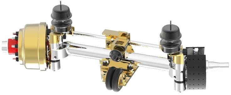
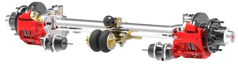
5 STANDARD STEER AXLE S Eveley International Corp. 4/15/ pg. 5

6 STANDARD STEER AXLE S Eveley International Corp. 4/15/ pg. 6

7 STANDARD STEER AXLE S3533 4/15/ pg. 7
8 SETTING CASTOR Bottom of king pin must point toward the front of the trailer Castor must be set when axle is set at ride height Factory setting is 1.5. Castor can be from /15/ pg. 8
9 AIRRIDE UNDERSLUNG AXLE SEAT WELDING SPECIFICATIONS Brackets which wrap around the axle should touch the axle as shown in view A in figure 3. With this type of fit, loads on the bracket are transferred directly to the axle. If a gap exists between the axle and the bracket as shown in view B in Fig.3, these loads are transferred to the weld. This may overstress and crack the weld. When welding axle seat in position mig welding is preferred. Welding wire should be 7018 or equivalent and should be performed so that welding is done in a flat position. If this is not possible welding should be performed using the stick method When an axle seat is attached to an axle with U-bolts and a weld, tighten the U-bolts to the specified torque 1000 ft/lbs (1356 N/m) before welding. This ensures that the load on the seat is not transferred into the weld. Before welding, remove all oil-paint and dirt from the surface to be welded. Check that the beam centres are correct, and that the axle fits tight into the axle seat, and that the U-bolts are torqued to the required specification. Never weld when the axle is cold. The axle and brackets to be welded should be stored overnight in a heated room and be at a temperature of at least 60ºF prior to welding. This will reduce the chance of forming an area of brittle material adjacent to the weld. If temperature requirements are not met, moderately pre-heat the weld area to a maximum temperature of 200ºF using a Rosebud. Do not concentrate heat in one area. Rather, slowly heat a wide area around the joint to be welded. Verify axle temperature using a temperature sensitive crayon or other appropriate means. The weld arc should not be started at the end of the bead. Instead, the electrode should be started away 4/15/ pg. 9
10 from the end of the bead and moved as shown in figure 5. The weld arc should not be finished at the end of the bead. Instead, the electrode should be finished away from the end of the bead as shown. Any craters which remain should be filled during this movement. Figure 5 After welding, the U-bolts should be checked to ensure that the torque specification has not changed. Do not weld on the bottom of the axle 4/15/ pg. 10
11 AIRRIDE TOPMOUNT AXLE SEAT WELDING SPECIFICATIONS Any approved 7018 Welding Rod or the equivalent, can be used. When welding the axle to the trailing beam saddle there must be three passes on each side, alternating, side to side and front to back. The finished weld size must be a minimum 1/2"(13mm) fillet weld. Ensure that each pass is done in different directions and starting points. Before welding, remove all oil-paint and dirt from the surface to be welded. Check that the beam centres are correct, and that the axle fits tight into the axle seat, and that the U-bolts are torqued to the required specification Never weld when the axle is cold. The axle and brackets to be welded should be stored overnight in a heated room and be at a temperature of at least 60ºF prior to welding. This will reduce the chance of forming an area of brittle material adjacent to the weld. If temperature requirements are not met, moderately pre-heat the weld area to a maximum temperature of 200ºF using a Rosebud. Do not concentrate heat in one area. Rather, slowly heat a wide area around the joint to be welded. Verify axle temperature using a temperature sensitive crayon or other appropriate means. The axle must be clamped to the axle saddle to ensure axle is seated securely in saddle. Axle must sit in saddle as shown in Figure 3. Page 9 Tack weld the axle saddle to the axle. A 1 long tack in the middle of the saddle front and back is sufficient The weld arc should not be started at the end of the bead. Instead, the electrode should be started away from the end of the bead and moved as shown in figure 6. The weld arc should not be finished at the end of the bead. Instead, the electrode should be finished away from the end of the bead as shown. Any craters which remain should be filled during this movement. Figure 6 4/15/ pg. 11
12 When welding the axle to the trailing beam saddle there must be three passes on each side, alternating, side to side and front to back. The finished weld size must be a minimum 1/2"(13mm) fillet weld. Ensure that each pass is done in different directions and starting points. See figure 3. Figure 3 4/15/ pg. 12
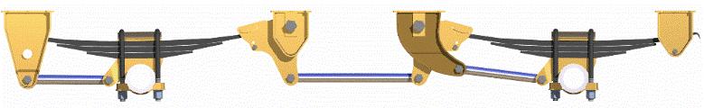
13 STEER AXLE INSTALLATION AND ALIGNMENT The Eveley steering axle assembly is manufactured and assembled with a TOE Value of zero (0) degrees Shipping braces are welded to axle to guarantee this setting does not change in the shipping process. These braces should not be removed until the assembly is securely attached to the trailer frame and aligned to the closest fixed axle assembly. Place the fixed axle in the position firs, ensure that the axle assembly is centered on the frame, and the dimensions are equal. Check dimension c king pin to center of spindle ends. This should be equal on both sides. Secure assembly to the frame. Place the steering axle assembly onto the frame at the required axle spacing. Ensure the steering axle assembly is centered on the frame and dimensions A are equal. Check the distance from the C/L on the spindle on the fixed axle to the C/L of the spindle on the steering axle dimension E. this dimension should be the same on both sides. For reference only check dimensions D trailer king pin to C/L steering axle king pins, both sides should be the same. Secure steering axle assembly to the frame 4/15/ pg. 13

14 TOE IN ALIGNMENT PROCEDURE Toe in alignment must be done with the trailer empty. Install tires, chalk a line around both tires for a reference to measure to. Set suspension to designed ride height. Operate the lock assembly, ensure that it has a clean entry into the sliding lock plate. Lock the axle in the fixed position and remove the shipping braces Release the tension on the tie rod clamps and the locking plate Check the tie rod chart below to determine the correct toe in dimension for your axle assembly. Check the dimensions across the chalk lines. Rotate the tie rod assembly to move the lines in at the front and out at the rear. The difference between the measurements at the front of the tires to the rear of the tires should be equal to the dimensions shown in the chart below. When completed, re-torque the tie rod end clamps and also the slider plate clamps to 150 ft lbs. Final check. Release the lock assembly. Steer the axle assembly in both directions to ensure that the tires do not interfere with the frame rail or air-spring. If adjustment is required it can be made by adjusting the steering bolt located on the back of the beam end. If adjustment is required, remember to lock the jam nut in place when you have completed the adjustment. FORWARD 4/15/ pg. 14
15 AIR CHAMBER ROD CUT LENGTHS When installing a new air chamber the actucting rod must be cut to a specific length in order for the brake system to function properly. Measure from the bottom of the chamber housing to the specified point on the rod. Cut rod at this dimension. 4/15/ pg. 15
16 SETTING THE AIRSPRING STABILZER Due to tire width, different load weights, trailer design, pressure settings will vary. This document is intended to assist the operator to maximize the use of the double convoluted air bag (dcab). Set the pressure in the control box at 30 psi with the trailer loaded. With the tires straight verify that there are 4 points of contact between stabilizer assembly and tie rod lock plate assembly Taking the trailer for a test drive increase the pressure to the airs bag until the tires start to resist turning while driving through a turn. Once the tires start to resist turning, back off the air bag pressure until the tires turn freely. If the axle shakes, shimmies or hops at highway speeds the centering air-spring requires adjustment, which should be done by a qualified steering axle technician. The geometry of the air suspension being used could affect the pressure settings required in the centering airspring. If the suspension air bag is above or ahead of the axle, more pressure may be required. If the air bag is behind the axle, less pressure may be required. 4/15/ pg. 16

17 4/15/ pg. 17

18 4/15/ pg. 18
19 STEER AXLE GREASE POINTS All cam tubes and grease points use DELO NLGI EP2 BLUE GREASE. It is recommended that a comparable grease be used when this is unavailable. 4/15/ pg. 19
20 EVERY 1,000 MILES Eveley International Corp. CHECK OIL LEVEL IN WHEEL HUB AND INSPECT FOR LEAKS 15,000 MILES OR TWICE A YEAR MINIMUM CHECK BRAKE ADJUSTMENT REPACK WHEEL BEARINGS (GREASE APPLICATION) 25,000-30,000 MILES CHECK BRAKE LINING AND REPLACE IF REQ D. INSPECT ALL CAMSHAFT BEARINGS AND SEALS FOR WEAR LUBRICATE CAMSHAFT BUSHING AND SLACK ADJUSTERS INSPECT BRAKE DRUMS FOR GLAZING GROOVES HOT SPOTS HEAT CRACKS OUT OF ROUND 100,000 MILES, ONCE A YEAR OR AT BRAKE RELINE REPLACE SPINDLE BEARING LUBRICATION INSPECT BRAKE CHAMBER AND SLACK ADJUSTERS INSPECT ALL BRAKE COMPONENTS AND REPLACE IF NECASSARY LUBRICATE CAMSHAFT BUSHINGS AND BRAKE ADJUSTERS 4/15/ pg. 20
21 NUT AND BOLT TORQUE SPECS It is very important to follow the manufacturers procedures and recommendations when dismantling and servicing some components on trailer axles and steer axles. For the proper procedures please refer to the manufacturers web sites listed below for more detailed information. Torque Specifications Hub Cap Bolts 5/16-18unc ft/lbs (22N/m) Air Chamber Mounting Bolts 5/8-11unc ft/lbs(156n/m) Dust Shield mounting Bolts 5/16-18unc ft/lbs(22n/m) Cam Bracket Mounting Bushing 5/16-18unc ft/lbs(22n/m) King pin cap 7/16-20 unf 50 ft lbs (68N/m) Draw Key 7/16-20 unf 50 ft lbs (68N/m) Steering Arms 7/8-14 unf 150 ft lbs (204N/m) Tie Rod Clamp Bolts 3/4-10 unc 150 ft lbs (204N/m) Lock Lever Housing Bolt 5/8-11 unc Lock must pivot freely Bellows Plate Bolt 3/8-16 unc 30 ft lbs (41N/m) Lever Arm Plate Bolt 5/8-11 unc Plate must pivot Lever Arm Pivot Bolt 1-8 unc Arm must pivot freely Lever Arm Adjusting Bolt 5/8-11 unc Adjust to position Lever Arm Adjusting Jam Nut 5/8-11 unc Tighten firmly Adjustable Stop Bolt 3/4-16 unf Adjust to position Adjustable Stop Jam Nut 3/4-16 unf Tighten firmly Any bolt or nut not listed please refer to industry standards 4/15/ pg. 21
22 KING PIN OVERHAUL AND REPLACEMENT PROCEDURE (NEEDLE BEARING) Remove the tie rod from the axle. Remove king pin caps and draw keys from axle. Discard the draw keys and O-rings. Support the knuckle while driving the king pin from the assembly. When the king pin is removed rotate the knuckle back and forth to free the thrust bearing and shims from the assembly. Save the shims for reassembly. Remove the seals from the top and bottom of the knuckle and discard. Drive the bearings from the knuckle bore. To do this, make a 2 sided mandrel. The first side have the diameter small enough to fit into the knuckle bore of the bearing. It will have to be long enough to push both bearings completely thru the knuckle bore. The other side of the mandrel should have a diameter so the bearing slips on and have a step which will bottom out when the bearing is flush with the top face of the knuckle. Discard the needle bearings. Inspect and clean all re-useable parts for reassembly. Replace worn parts. Using the mandrel, gently drive the first bearing into the bore followed by the second. 4/15/ pg. 22
23 Slide the king pin thru the installed bearings and make sure it rotates freely. If not remove the bearings and hone the knuckle bore. To install the seal, place the closed end facing into the bore of the knuckle. Place a round disc / plate on top of the seal. Using the king pin gently tap the disc / plate until the seal is seated. To reassemble the knuckle to the beam end, align the bore holes so that the king pin can be inserted. Partially insert the king pin so that the shim / shims can be inserted where shown. Insert as many or different thickness of shims so that the thrust bearing has to be gently tapped in by a rubber mallet. Align the king-pins so the draw key slots match up with the holes in the beam ends. The king-pins are marked LH and RH. The markings are on the top sides of the king pins. The beam ends are also marked LT and RT to designate top left or right hand side. Drive the king pin in using a rubber mallet or a hammer with some king of protection for the king pin (hard wood Lumber / brass rod). Center the king pin so equal spacing can be felt by hand on the outside knuckle faces. Drive the draw keys in alternately with the flats facing towards the king pin. Torque the flange nuts to 50 ft-lbs. After 1,000mi (1,600km) re-torque. Bolt the king pin caps on with new O-rings installed. Grease until you can see it escaping from the beam ends. 4/15/ pg. 23
24 KING PIN OVERHAUL AND REPLACEMENT PROCEDURE ( EVELEY BUSHING ) Remove the tie rod from the axle. Remove king pin caps and draw keys from axle. Discard the draw keys and 0-rings. Support the knuckle while driving the king pin from the assembly. When the king pin is removed rotate the knuckle back and forth to free the thrust bearing and shims from the assembly. Save the shims for reassembly. Remove the seals from the top and bottom of the knuckle and discard. With a screw driver or needle nose pliers, lift the end of the Eveley bushing out of the knuckle bore. Grab the removed part of the Eveley bushing with a pair of pliers and rotate the bushing out from the bore. Inspect and clean all re-useable parts for reassembly. Replace worn parts. By hand rotate and push the Eveley bushing into the knuckle bore. When the bushing is partially started, use pliers to completely install it. When finished the bushing should be just below the knuckle / king pin cap face. Slide the king pin thru the installed Eveley bushings and make sure the king pin rotates by hand. If not remove the bushings and hone the knuckle bore. To install the seal, place the closed end facing into the bore of the knuckle. Place a round disc / plate on top of the seal. Using the king pin gently tap the disc / plate until the seal is seated. 4/15/ pg. 24
25 To reassemble the knuckle to the beam end, align the bore holes so that the king pin can be inserted. Partially insert the king pin so that the shim / shims can be inserted where shown. Insert as many or different thickness of shims so the thrust bearing has to be gently tapped in by a rubber mallet. Align the king pins so that the draw key slots match up with the holes in the beam ends. The king pins are marked LH and RH. The markings are on the top sides of the king pins. The beam ends are also marked LT and RT to designate the top left or right hand side. Drive the king pin in using a rubber mallet or a hammer with some kind of protection for the king pin (hard wood lumber / brass rod). Center the king pin so equal spacing can be felt by hand on the outside knuckle faces. Drive the draw keys in alternately with the flats facing toward the king pin. Torque the flange nuts to 50ft.lbs. After 1,000mi (1,600km) re-torque. Bolt the king pin caps on with new O-rings installed. Grease until you can see it escaping from the beam end 4/15/ pg. 25
26 GENERAL INFORMATION This Eveley International Axle Installation and Maintenance Manual includes information to assist you in identifying correct part numbers and ordering appropriate parts. When ordering genuine Eveley International replacement parts, please be sure you have the correct part number and description. If the part number is not available the axle part number will be required. Descriptions and specifications contained in this manual were in effect at the time of publication, and are subject to change without notice or liability. All shipments are F.O.B. shipping point Stoney Creek, Ontario. Exploded Parts Views contained in this manual are not to scale and may not show all parts included on the axle. These views are for reference only. Note: Many of our parts are now available packaged for re-sale or stocking. These parts come individually packed with part number identification on each package. CUSTOMER SERVICE DEPARTMENT Telephone: (905) North.America: Fax (905) Mailing: 665 ARVIN AVE Stoney Creek, Ontario L8E-5R2 PARTS DEPARTMENT Telephone: (905) North.America: Fax (905) Mailing: 2814 BARTON ST E Stoney Creek, Ontario L8E-1V6 4/15/ pg. 26
27 EVELEY INTERNATIONAL CORP. PRODUCT WARRANTY This warranty shall be limited to the original purchaser from the date of sale and covers all new components manufactured by Eveley International Corp. to be free of defects in material and workmanship, for one year (parts and labour) and up to five years (parts only) when installed, assembled, and maintained in accordance with Eveley International Corp. installation and maintenance procedures, under normal use and service. The product installer is responsible for providing correct vehicle components and attachments, and providing the clearance for suspension components, axles, wheels and tires. The installer is also responsible to ensure that products supplied by Eveley International Corp. are operating within their engineering designed capabilities and capacities. The product owner is responsible for pre-operation inspection, periodic inspections, maintenance, and use of the product as specified by Eveley International Corp. This warranty is null and void if the products are subject to improper installation, modification, adjustment, unauthorized repair, damage as a result of abuse, accident, and /or negligence, and incorrect or insufficient maintenance or applications, including but not limited to, overloading product ratings or maximum vehicle weight specifications. This warranty is null and void if parts failure or system problems occur as a result of incorrect trailer or frame design. This is the responsibility of the trailer or equipment manufacturer. The responsibility under this warranty is limited to the replacement or repair of defective parts at no charge and is at the discretion of Eveley International Corp. Products to be considered for warranty are to be returned pre-paid to Eveley International Corp.and will be subject to our inspection, or the field inspection by an authorized representative of Eveley International Corp. before warranty is approved. In no event shall Eveley International Corp. be liable for any expense, loss or damage (direct, Incidental, consequential, or exemplary) including, but not limited to, towing expenses, equipment rental, downtime expenses, cargo damage, incidental expenses, or any other losses arising in connection with the sale, use or inability to use the product resulting from a warranty covered part found to be defective. Any allowance for labour costs associated with the repair or replacement of the subject component must be pre-approved in writing by Eveley International Corp. Component parts included in the Eveley International Corp. product but purchased from outside vendors are guaranteed by Eveley International Corp. to the same extent as the guarantee offered by the outside vendor to Eveley International Corp. Any Warranty implied by law, including any warranty of merchantability or fitness for a particular purpose, is limited to the expressed warranty terms provided in this warranty coverage. All wearable items are not included in this warranty. This warranty is limited to normal on highway use or written approval applications. This warranty does not cover, off road, mining, or raw wood applications. This warranty coverage is for Canada and the United States only. The use of none-genuine Eveley International Corp. replacement parts will void this warranty coverage. No other warranty is expressed or implied by Eveley International Corp. 4/15/ pg. 27
INSTALLATION AND MAINTENANCE MANUAL. ROADTRACKtm RTD SUSPENSION
 INSTALLATION AND MAINTENANCE MANUAL ROADTRACKtm RTD SUSPENSION Roadtrack RTD Series Suspension The ROADTRACK series suspension system is a three point system available in undermount or underslung set-ups.
INSTALLATION AND MAINTENANCE MANUAL E6100 SERIES SPRING SUSPENSION
 INSTALLATION AND MAINTENANCE MANUAL E6100 SERIES SPRING SUSPENSION E6100 Series Spring Suspension The E6100 series suspension system is a three point system available in undermount or underslung set-ups.
SuperTrac. Axle. Service & Maintenance. Manual
 SuperTrac Axle Service & Maintenance Manual Table of Contents Page Exploded Views Section 1: General Information General Warnings Description of Axle Models Identifications Section 2: Installation Axle
OWNER S GUIDE 8A DURALIFT II 13,200 LB. CAPACITY. Link Mfg. Ltd th St. N.E. Sioux Center, IA USA
 OWNER S GUIDE 8A000715 DURALIFT II 13,200 LB. CAPACITY Link Mfg. Ltd. 223 15th St. N.E. Sioux Center, IA USA 51250-2120 www.linkmfg.com QUESTIONS? CALL CUSTOMER SERVICE 1-800-222-6283 DEALER / INSTALLER:
MS2200, MS2500, and MS3000 Suspension Installation Manual ON/OFF HIGHWAY SUSPENSION SYSTEM
 MS22, MS25, and MS3 Suspension Installation Manual ON/OFF HIGHWAY SUSPENSION SYSTEM 972.547.62 8.445.736 FAX: 972.542.97 725 E. UNIVERSITY ST. McKINNEY, TEXAS 7569 www.watsonsuspensions.com Watson & Chalin
RSS K Truck Self-Steering Air-Ride Suspension
 RSS-233-20K Truck Self-Steering Air-Ride Suspension Installation and Service Manual Suspension Identification... 2 Suspension System Serial Tag Installation... 3 Prior to Installation Suspension Mounting
SPECIFICATIONS CONTENTS: Specifications Warning Information. Operating Instructions Preventative Maintenance and Troubleshooting
 Model 3322 22 Ton Air/Hydraulic Truck Axle Jack OWNER'S MANUAL CONTENTS: Page 1 Page 2 Page 3-4 Page 4-5 Page 5 Page 6 Page 7 Page 8 Specifications Warning Information Assembly Operating Instructions Preventative
1988 Chevrolet Pickup V SUSPENSION - FRONT (4WD)' 'Front Suspension - "V" Series 1988 SUSPENSION - FRONT (4WD) Front Suspension - "V" Series
' 'Front Suspension - V Series 1988 SUSPENSION - FRONT (4WD) Front Suspension - V Series") 1988 SUSPENSION - FRONT (4WD) Front Suspension - "V" Series DESCRIPTION NOTE: Vehicle serial numbers used in this article has been abbreviated for common reference to Chevrolet and GMC models. Chevrolet
1988 SUSPENSION - FRONT (4WD) Front Suspension - "V" Series DESCRIPTION NOTE: Vehicle serial numbers used in this article has been abbreviated for common reference to Chevrolet and GMC models. Chevrolet
RAR Stub Axle Suspension Trailer Air-Ride Suspension
 RAR-251 - Stub Axle Suspension Trailer Air-Ride Suspension Installation and Service Manual Suspension Identification... 2 Suspension System/Axle Serial Tag Installation... 3 Prior to Installation Axle
RSS-233T - 13K Trailer Self-Steering Air-Ride Suspension
 RSS-233T - 13K Trailer Self-Steering Air-Ride Suspension Installation and Service Manual Suspension Identification... 2 Suspension System Serial Tag Installation... 3 Torque Specifications Prior to Installation
Refer to separate Installation Instructions for installation details.
 OWNER S GUIDE 8A000729 DuraLift 13.5 13,500 CAPACITY Link Mfg. Ltd. 223 15th St. N.E. Sioux Center, IA USA 51250-2120 www.linkmfg.com QUESTIONS? CALL CUSTOMER SERVICE 1-800-222-6283 DEALER / INSTALLER:
Please visit for the latest version of these installation instructions.
 Please visit www.blueox.com for the latest version of these installation instructions. 2014-2017 Ram 2500 (All beds) Please read these in their entirety prior to installing or operating this equipment.
TC Series Front Axle. TC Series Front Axle 010-1
 TC Series Front Axle Blue Bird Corporation assumes sole responsibility for ensuring that the information provided herein is accurate to the best of its knowledge at the time of printing. In keeping with
Heavy Duty Front-Drive Steer Axles MX-140 and MX-160 Series
 Revised 11/2009 Heavy Duty Front-Drive Steer Axles MX-140 and MX-160 Series Catalog PB-0349 Strength Power Speed Agility MERITOR PARTS. RIGHT FROM THE START. TABLE OF CONTENTS MX-17/19/21-140 and MX-21/23-160
RSS Truck Suspension Self-Steer Air-Ride Suspension System for Customer-Supplied I-Beam Axle
 RSS-2361000-Truck Suspension Self-Steer Air-Ride Suspension System for Customer-Supplied I-Beam Axle Installation and Service Manual Suspension Identification... 2 Suspension System Serial Tag Prior to
RSS K Truck Self-Steering Auxiliary Axle Suspension
 RSS-233-13K Truck Self-Steering Auxiliary Axle Suspension Installation and Service Manual Suspension Identification... 2 Suspension System Serial Tag Installation... 3 Torque Specifications Prior to Installation
Installing RideSentry Suspension Axle Seats onto RideStar RHP Series Single-Axle and Sliding Tandem Trailer Air Suspension Systems
 Issued 10-07 Technical Bulletin Installing RideSentry Suspension Axle Seats onto RideStar RHP Series Single-Axle and Sliding Tandem Trailer Air Suspension Systems Issued 1 Technical 10-07 Bulletin Hazard
CHEVY / GMC 1500HD / 2500HD 2WD 8 LUG 7 BASIC KIT
 85101 2000-2010 CHEVY / GMC 1500HD / 2500HD 2WD 8 LUG 7 BASIC KIT C8510-4 MAIN BOX KIT W/ HARDWARE 1) FRONT X MEMBER 1) REAR X MEMBER 2) TORSION BAR DROPS 1) LEFT BUMP STOP 1) RIGHT BUMP STOP 2) SWAY BAR
RSS K Truck Self-Steering Auxiliary Axle Suspension
 RSS-233-10K Truck Self-Steering Auxiliary Axle Suspension Installation and Service Manual Suspension Identification... 2 Suspension System Serial Tag Installation... 3 Torque Specifications Prior to Installation
RSS-233T - 13K Trailer Self-Steering Air-Ride Suspension
 RSS-233T - 13K Trailer Self-Steering Air-Ride Suspension Installation and Service Manual Suspension Identification... 2 Suspension System Serial Tag Installation... 3 Torque Specifications Prior to Installation
RSS-233T - 20K Trailer Self-Steering Air-Ride Suspension
 RSS-233T - 20K Trailer Self-Steering Air-Ride Suspension Installation and Service Manual Suspension Identification... 2 Suspension System Serial Tag Installation... 3 Prior to Installation Suspension Mounting
BRAKE SYSTEM Toyota Celica DESCRIPTION DRUM BRAKES ADJUSTMENTS BRAKE PEDAL HEIGHT ADJUSTMENTS BRAKE PEDAL FREE PLAY ADJUSTMENTS
 BRAKE SYSTEM 1988 Toyota Celica 1988-89 BRAKES Toyota Celica, Corolla, MR2, Tercel DESCRIPTION The hydraulic brake system uses a tandem master cylinder with a vacuum power assist servo. MR2 and some Celica
Deere G & GP Series Snow Wing Installation
 Deere G & GP Series Snow Wing Installation Model: Serial Number: Rev. 10/13 Rylind Manufacturing, Inc. 2801 Youngfield St Suite 250 Golden, CO 80401 Offices: 303-979-3548 Fax: 303-979-4730 www.rylind.com
Installation Instructions
 85-3180 rev. 07 03-14 Installation Instructions Thank you for purchasing this antisway bar kit. Please read through these instructions before installation. Front Anti-Sway Bar Kit for the Ford E350/450
RSS-232/232T 20K Truck and Trailer Self-Steering Auxiliary Axle Suspension
 RSS-232/232T 20K Truck and Trailer Self-Steering Auxiliary Axle Suspension RSS-232 - Truck suspension shown Installation and Service Manual Suspension Identification... 2 Suspension System Serial Tag Installation...
FRONT & 4 REAR GM WD LOWERING KIT
 92725200 88-98 2 FRONT & 4 REAR GM 1500 2WD LOWERING KIT Thank you for choosing Rough Country for all your suspension needs. Rough Country recommends a certified technician install this system. In addition
INSTALLATION INSTRUCTIONS FOR M.O.R.E. SHACKLE REVERSAL SYSTEM (S.R.S. ) PART # THIS SYSTEM FITS Jeep CJ-5, CJ-7, CJ-8 VEHICLES.
 PART # THIS SYSTEM FITS Jeep CJ-5, CJ-7, CJ-8 VEHICLES.") INSTALLATION INSTRUCTIONS FOR M.O.R.E. SHACKLE REVERSAL SYSTEM (S.R.S. ) PART # 7686-6 THIS SYSTEM FITS 1976-1986 Jeep CJ-5, CJ-7, CJ-8 VEHICLES. Please read all instructions carefully (including terms-policies)
INSTALLATION INSTRUCTIONS FOR M.O.R.E. SHACKLE REVERSAL SYSTEM (S.R.S. ) PART # 7686-6 THIS SYSTEM FITS 1976-1986 Jeep CJ-5, CJ-7, CJ-8 VEHICLES. Please read all instructions carefully (including terms-policies)
Technical Support Line: (952) Hanover Ave. Lakeville, MN
 Hanover Ave. Lakeville, MN") Technical Support Line: (952) 985-5675 Email: Sales@QA1.net 21730 Hanover Ave. Lakeville, MN 55044 www.qa1.net INSTALLATION INSTRUCTIONS QA1 1967-1979 Mopar A-Body Rear 6 link Conversion System QA1 p/n
Technical Support Line: (952) 985-5675 Email: Sales@QA1.net 21730 Hanover Ave. Lakeville, MN 55044 www.qa1.net INSTALLATION INSTRUCTIONS QA1 1967-1979 Mopar A-Body Rear 6 link Conversion System QA1 p/n
RSS-232/232T - 8K-10K-13K Self-Steering Auxiliary Axle Suspension
 RSS-232/232T - 8K-10K-13K Self-Steering Auxiliary Axle Suspension Installation and Service Manual Suspension Identification... 2 Suspension System Serial Tag Installation... 3 Prior to Installation Suspension
Trailer Suspensions & Components
 Warranty Statement Trailer Suspensions & Components This warranty applies to suspensions manufactured by CUSH Corp that have been properly assembled and installed by the OEM. It applies to product that
Rhino Long Travel Spindle Kit Yamaha Rhino FTR10072
 4331 EUCALYPTUS AVE. ~~ CHINO, CA 91710 909-597-7800 Fax 909-597-7185 Rhino Long Travel Spindle Kit 2005-08 Yamaha Rhino FTR10072 PARTS LIST: QTY. Part # Description 1 FTS95061D Rhino Spindle Driver 1
Feb 22, 2018 '67-69 Camaro & '68-74 Nova Bumpsteer Adjustment Kit
 Feb 22, 2018 '67-69 Camaro & '68-74 Nova Bumpsteer Adjustment Kit 10552 The following instructions are intended for professional installers. Speedtech Performance assumes NO responsibility for the installation
TOOL LIST: (NOT INCLUDED) FLOOR JACK JACK STANDS ASSORTED METRIC AND S.A.E SOCKETS, & ALLEN WRENCHES DIE GRINDER WITH CUTOFF WHEEL
 FLOOR JACK JACK STANDS ASSORTED METRIC AND S.A.E SOCKETS, & ALLEN WRENCHES DIE GRINDER WITH CUTOFF WHEEL") www.fabtechmotorsports.com 4331 EUCALYPTUS AVE. ~~ CHINO, CA 91710 909-597-7800 FAX 909-597-7185 2000-08 FORD RANGER 2WD FTS98200-7 3.5 LIFT SPINDLES PARTS LIST: 1 EA. PASS. SPINDLE FTS98200-7P 1 EA. DRIV.
www.fabtechmotorsports.com 4331 EUCALYPTUS AVE. ~~ CHINO, CA 91710 909-597-7800 FAX 909-597-7185 2000-08 FORD RANGER 2WD FTS98200-7 3.5 LIFT SPINDLES PARTS LIST: 1 EA. PASS. SPINDLE FTS98200-7P 1 EA. DRIV.
INSTALLATION OF RAILGEAR KIT R-290HD REAR
 INSTALLATION OF RAILGEAR KIT R-290HD REAR Page 1 of 29 SAFETY PRECAUTIONS If any installation problems are encountered, please call G&B Specialties, Inc. for technical assistance before continuing with
TOOL LIST: (NOT INCLUDED) FLOOR JACK JACK STANDS ASSORTED METRIC AND S.A.E SOCKETS, & ALLEN WRENCHES DIE GRINDER WITH CUTOFF WHEEL
 FLOOR JACK JACK STANDS ASSORTED METRIC AND S.A.E SOCKETS, & ALLEN WRENCHES DIE GRINDER WITH CUTOFF WHEEL") www.fabtechmotorsports.com 4331 EUCALYPTUS AVE. ~~ CHINO, CA 91710 909-597-7800 FAX 909-597-7185 2000-08 FORD RANGER 2WD FTS98200-73 3.5 LIFT SPINDLES PARTS LIST: 1 EA. PASS. SPINDLE FTS98200-73P 1 EA.
www.fabtechmotorsports.com 4331 EUCALYPTUS AVE. ~~ CHINO, CA 91710 909-597-7800 FAX 909-597-7185 2000-08 FORD RANGER 2WD FTS98200-73 3.5 LIFT SPINDLES PARTS LIST: 1 EA. PASS. SPINDLE FTS98200-73P 1 EA.
12-1/4 x 3-1/2 Electric Wheel Brake
 12-1/4 x 3-1/2 Electric Wheel Brake A-216 819-0244 Installation Instructions An Altra Industrial Motion Company Contents Dimensions.... 2 Technical Specifications.... 3 Installation Instructions General....
Installation Instructions
 Preparing your vehicle to install your brake system upgrade 1. Rack the vehicle. 2. If you don t have a rack, then you must take extra safety precautions. 3. Choose a firmly packed and level ground to
SECTION ZF FRONT AXLE
 04-101.01/ 1 2011JA14 SECTION 04-101.01 6 3 5 1 2 9 1. Upper radius rod 2. Lower radius rod 3. Caliper 4. BRAKE Disk 5. Pneumatic connector 6. Hub 7. steering knuckle 8. Grease Fitting 9. Pneumatic connector
WARNING: Only perform this installation if you are experienced, fully equipped mechanic.
 DYNATRAC V3.2 2005-Present Ford Super Duty 250/350-4x4, Front Axle, Free Spin Conversion Kit Some of the less common tools, which will be required: 6 point Spanner socket (OTC #7090-A or equivalent). These
INSTALLATION AND MAINTENANCE MANUAL
 IMPORTANT This manual must accompany the trailer when delivered to the end user. INSTALLATION AND MAINTENANCE MANUAL ISS Series Suspensions 347 King Street West, Ingersoll, Ontario, Canada, N5C 3K6 Ph:
Installation Guide. Spring Steer Suspensions. Air-Weigh Customer Support: Welded Steer Brackets PN R0
 Installation Guide Spring Steer Suspensions Welded Steer Brackets Air-Weigh Customer Support: 888-459-3247 PN 901-0146-003 R0 1 Table of Contents Overview...1 Tools Required...1 Installing the Sensor Bracket...2
1984 Dodge W250 PICKUP
 1984 Dodge W250 PICKUP Submodel: Engine Type: V8 Liters: 5.2 Fuel Delivery: CARB Fuel: GAS Dana 44 MODELS THROUGH 1984 2. Raise and safely support the vehicle, then remove the wheel hub and bearings as
INSTALLATION INSTRUCTIONS FOR PLEASE READ AND UNDERSTAND TERMS/POLICIES BEFORE YOU INSTALL THIS SYSTEM
 MOUNTAIN OFF ROAD ENTERPRISES. LLC. P.O. BOX 690 DELTA, COLORADO 81416 970-625-0500 E-mail: info@mountainoffroad.com www.mountainoffroad.com INSTALLATION INSTRUCTIONS FOR 8795-2 PLEASE READ AND UNDERSTAND
DYNATRAC PRODUCTS V5.3
 DYNATRAC PRODUCTS V5.3 2000-2008 Dodge Hub Kit Stage 1 4x4, Front Axle Free Spin Conversion Kit Note: This Kit is not Approved for 2007 & up 3500 Cab and Chassis Trucks Due to a Larger U-Joint (If U-Joint
ASSORTED METRIC WRENCHES AND SOCKETS RED LOCTITE (PERMATEX 271) HAMMERS, CUTTERS, DRILL MOTOR W/ 3/8 BIT MIG WELDER
 HAMMERS, CUTTERS, DRILL MOTOR W/ 3/8 BIT MIG WELDER") 4331 EUCALYPTUS AVE. ** CHINO, CA. 91710 909-597-7800 Fax 909-597-7185 1984-95 TOYOTA 2 WHEEL DRIVE FTS4130-ID LONG TRAVEL KIT PARTS LIST: 1 EA. RIGHT UPPER CONTROL ARM (UCA) 1 EA. LEFT UPPER CONTROL ARM
4331 EUCALYPTUS AVE. ** CHINO, CA. 91710 909-597-7800 Fax 909-597-7185 1984-95 TOYOTA 2 WHEEL DRIVE FTS4130-ID LONG TRAVEL KIT PARTS LIST: 1 EA. RIGHT UPPER CONTROL ARM (UCA) 1 EA. LEFT UPPER CONTROL ARM
INSTALLATION GUIDE DIRECT-REPLACEMENT
 DIRECT-REPLACEMENT INSTALLATION GUIDE FJ CRUISER (10+) 4RUNNER (10+) 883-06-111-2.5 Factory Series Coil-Over Reservoir - Adjustable 883-02-111-2.5 Factory Series Coil-Over Reservoir 880-02-361-2.5 Factory
1 Part Number: M-2300-Y Part Description: S550 Mustang-Shelby Brake Upgrade Kit Installation Instructions
 Please visit www.performanceparts.ford.com for the most current instruction and warranty information. PLEASE READ ALL OF THE FOLLOWING INSTRUCTIONS CAREFULLY PRIOR TO INSTALLATION. AT ANY TIME YOU DO NOT
Please visit for the latest version of these installation instructions.
 Please visit www.blueox.com for the latest version of these installation instructions. DH2400 (Long & Standard Box) Please read these in their entirety prior to installing or operating this equipment.
TMC 90 SPRING SUSPENSION
 TMC 90 SPRING SUSPENSION INSTALLATION and SERVICE MANUAL TMC AUSTRALIA PTY LTD Telephone: + (61) 3 8786 3688 78 Star Crescent, P.O. Box 5028 Facsimile: + (61) 3 8786 3699 Hallam, Victoria, 3083 E-mail:
INSTALLATION GUIDE DIRECT-REPLACEMENT
 DIRECT-REPLACEMENT INSTALLATION GUIDE TACOMA (05+) 880-06-376-2.5 Factory Series Coil-Over Reservoir - Adjustable 880-06-418-2.5 Factory Series Coil-Over Reservoir - Adjustable 880-02-376-2.5 Factory Series
DIAGNOSIS AND TESTING
 DIAGNOSIS AND TESTING SUSPENSION AND STEERING SYSTEM 2007 SUSPENSION Suspension - Nitro CONDITION POSSIBLE CAUSES CORRECTION FRONT END NOISE 1. Loose or worn wheel bearings. 1. Replace wheel bearings.
Replacement Steering Stabilizer Kit
 Replacement Steering Stabilizer Kit Installation Manual: for 87-95 (YJ) and 97-06 (TJ) Wrangler # 16116.0200 PARTS LIST: Steering Damper Black Boot & Boot Tie Decal Hourglass Bushing - Qty 2 Sleeve - Qty
MERITOR MEDIUM DUTY FRONT-DRIVE STEER AXLES MX-120, MX-120 HR AND MX-120-EVO SERIES PB-02167
 MERITOR MEDIUM DUTY FRONT-DRIVE STEER AXLES MX-120, MX-120 HR AND MX-120-EVO SERIES PB-02167 Meritor.com/lod With a user-friendly approach and visually appealing format for easier, quicker surfing, Literature
Installation Instructions
 Nov 25, 2013 Upper Control Arms Installation Instructions The following instructions are intended for professional installers and are guidelines only. Speedtech Performance assumes NO responsibility for
CHEVY C WHEEL DRIVE FTS " LIFT SPINDLES
 www.fabtechmotorsports.com 4331 EUCALYPTUS AVE. CHINO, CA. 91710 PHONE 909-597-7800 FAX 909-597-7185 1988-1998 CHEVY C1500 2 WHEEL DRIVE FTS1588-7 4" LIFT SPINDLES PARTS LIST: FTS1588-7 Chevy 4"Lift Spindle
Installation Notes: #86000-R Race Series +3.5 L/T Kit
 159 North Maple St. Unit J, CORONA CA 92880 P. 951-737-9682 F. 951-737-9006 WWW.CHAOSFAB.COM Installation Notes: #86000-R Race Series +3.5 L/T Kit Factory manual is recommended for removal and re-installation
INSTALLATION INSTRUCTIONS QA1 P/N x400, x500, x600, x400, x500, x F100 Front Coil-over Suspension System
 INSTALLATION INSTRUCTIONS QA1 P/N 52620-x400, 52620-x500, 52620-x600, 52621-x400, 52621-x500, 52621-x600 65-72 F100 Front Coil-over Suspension System TOOLS AND SUPPLIES REQUIRED Floor Jack Two (2) Jack
INSTALLATION INSTRUCTIONS MOUNTING KIT FOR ELITE SERIES
 INSTALLATION INSTRUCTIONS MOUNTING KIT FOR ELITE SERIES DO NOT EXCEED VEHICLE MANUFACTURER S RATING FOR 5th WHEEL TOWING OR MAXIMUM GROSS TRAILER WEIGHT OF 18,000lb. / 8160kg. DEALER/INSTALLER: (1) Provide
DRIVE AXLE Volvo 960 DESCRIPTION & OPERATION AXLE IDENTIFICATION DRIVE AXLES Volvo Differentials & Axle Shafts
 DRIVE AXLE 1994 Volvo 960 1994 DRIVE AXLES Volvo Differentials & Axle Shafts 960 DESCRIPTION & OPERATION All 960 station wagon models use type 1041 rear axle assembly. All 960 4-door models use type 1045
INTRODUCTION. Safety Warnings
 INTRODUCTION The purpose of this manual is to familiarize yourself with an IMT axle. Topics included will cover: Installation Adjustments Maintenance Inspections This manual also contains information in
INSTALLATION INSTRUCTIONS
 INSTALLATION INSTRUCTIONS INSTRUCTION FOR ASSEMBLY OF JEEP CJ SERIES W/AMC 20 REAR AXLES, 5 x 5-1/2" BOLT CIRCLE WITH A130-1 FULL FLOATING AXLE OR A130-2 (1 PIECE AXLE) Thank you for choosing STAINLESS
SUSPENSION 2-1 SUSPENSION TABLE OF CONTENTS
 XJ SUSPENSION 2-1 SUSPENSION TABLE OF CONTENTS page ALIGNMENT... 1 FRONT SUSPENSION... 7 page REAR SUSPENSION... 16 ALIGNMENT TABLE OF CONTENTS page AND WHEEL ALIGNMENT...1 DIAGNOSIS AND TESTING SUSPENSION
INSTALLATION GUIDE DIRECT-REPLACEMENT
 DIRECT-REPLACEMENT INSTALLATION GUIDE TITAN (04+) 883-06-120-2.5 Factory Series Coil-Over Reservoir - Adjustable 883-02-120-2.5 Factory Series Coil-Over Reservoir 983-02-053-2.0 Performance Series Coil-Over
51201 INSTALLATION INSTRUCTIONS
 7929 Lincoln Ave. Riverside, CA 92504 Phone: 951.689.ICON Fax: 951.689.1016 PART # 51201 51201 INSTALLATION INSTRUCTIONS DESCRIPTION 07-UP TUNDRA MULTI-RATE RXT LEAF SPRING KIT 1-22-2019 REV.B COMPONENTS
RAR Lightweight Trailer Suspension Owner s Manual. P.O. Box 4586 Springfield, MO
 RAR-243 Lightweight Trailer Suspension Owner s Manual www.ridewellcorp.com P.O. Box 4586 Springfield, MO 65808 417.833.4565 417.833.4560 (fax) 0711 Suspension Identification: Ridewell Suspensions are identified
2017-Present Can-Am Maverick X3 XRS Front Upper A-Arm Kit *Installation Instructions*
 2017-Present Can-Am Maverick X3 XRS Front Upper A-Arm Kit *Installation Instructions* PART# 370-90350 Introduction - Installation requires a qualified mechanic. - Read instructions carefully and study
Installation Instructions
 Installation Instructions Rear Disc Brake Conversion Kit Item # RC2001, RC2001X Applications: Mopar 8-3/4 & 9-3/4 Rear Axles Thank you for choosing Leed Brakes for your automotive product needs. Before
6-TON DOUBLE LOCKING JACK STANDS OWNER S MANUAL
 6-TON DOUBLE LOCKING JACK STANDS OWNER S MANUAL WARNING: Read carefully and understand all ASSEMBLY AND OPERATION INSTRUCTIONS before operating. Failure to follow the safety rules and other basic safety
Quadratec 3 Add-A-Leaf Suspension Lift Kit
 Quadratec 3 Add-A-Leaf Suspension Lift Kit Installation Manual: for 1984-2001 Cherokee (XJ) # 16400.005X PARTS LIST: Front Coil Springs - QTY 2 Add-A-Leafs - QTY 2 5/16 x 3 Tie Bolts - QTY 2 5/16 Tie Bolt
SPL HICAS ELIMINATOR KIT
 SPL HICAS ELIMINATOR KIT Steps to installing the Hicas eliminator kit: 1. Unbolt and remove Hicas actuator. 2. Remove Hicas ball joint and install toe bushing 3. Install Hicas eliminator bracket and toe
TRAILER INSTALLATION INSTRUCTIONS
 TRAILER INSTALLATION INSTRUCTIONS 8A000450 DuraMax 20,000 LB. CAPACITY Link Mfg. Ltd. 223 15th St. N.E. Sioux Center, IA USA 51250-2120 www.linkmfg.com QUESTIONS? CALL CUSTOMER SERVICE 1-800-222-6283 Refer
TMC 75 SPRING SUSPENSION
 TMC 75 SPRING SUSPENSION SERVICE MANUAL TMC Australia Pty Ltd Telephone: + 61 3 8786 3688 78 Star Crescent Facsimile: + 61 3 8786 3699 Hallam E-Mail: info@tmcaus.com.au Victoria 3803 Australia www.tmcaustralia.com.au
CONTENTS. VIKING PUMP, INC. A Unit of IDEX Corporation Cedar Falls, IA USA SECTION TSM 710.1
 TECHNICAL SERVICE MANUAL industrial heavy duty motor speed pumps SERIES 4076 AND 4176 SIZES hle, ate and ale SECTION TSM 710.1 PAGE 1 of 8 ISSUE B CONTENTS Introduction....................... 1 Safety
INSTALLATION GUIDE DIRECT-REPLACEMENT
 DIRECT-REPLACEMENT INSTALLATION GUIDE TUNDRA (07+) 985-02-004: 2.0 Performacne Series Coil-over IFP 883-02-021: 2.5 Factory Series Coil-over IFP 880-02-367: 2.5 Factory Series Coil-over Reservoir 880-06-367:
Once properly aligned weld axle saddles to axle using welding practice as below.
 INSTALLATION & MAINTENANCE GUIDE 50 Series Suspensions Shackle bolts and rocker pivot bolts fitted with Nyloc type nuts must be tightened firmly allowing for rotational movement of bushed components. All
Rhino Long Travel Spindle Kit Loaded Yamaha Rhino FTR10074
 4331 EUCALYPTUS AVE. ~~ CHINO, CA 91710 909-597-7800 Fax 909-597-7185 Rhino Long Travel Spindle Kit Loaded 2005-08 Yamaha Rhino FTR10074 PARTS LIST: FTR10074 Rhino Spindles FT95232 Hdwr Sub-Assembly Kit
Hydraulic Wheel Dolly
 Hydraulic Wheel Dolly Operating Instructions & Parts Manual Model Number HW93765 Capacity 3/4 Ton Made in the U.S.A. This is the safety alert symbol. It is used to alert you to potential personal injury
Installation Instructions FRONT SUSPENSION INSTRUCTIONS: 1) Disconnect the negative terminal on the battery.
 Disconnect the negative terminal on the battery.") 75004 75001-5 COPONENT BOX 1 1) Rear Cross Member 1) Front Cross Member 1) Left Strut Spacer 1) Right Strut Spacer 2) Sway Bar Drops 1) Left Compression Strut 1) Right Compression Strut 2) Tie rods T538
75004 75001-5 COPONENT BOX 1 1) Rear Cross Member 1) Front Cross Member 1) Left Strut Spacer 1) Right Strut Spacer 2) Sway Bar Drops 1) Left Compression Strut 1) Right Compression Strut 2) Tie rods T538
Installation Instructions
 85-4341 rev. 04 10-15 Installation Instructions Thank you for purchasing this antisway bar kit. Please read through these instructions before installation. Rear Anti-Sway Bar Kit for Chevy 2500/3500/4500
2 Strut Spacer / Preload Lift. Ford Ranger 4wd Part#:
 Part#: 013203 2 Strut Spacer / Preload Lift Ford Ranger 4wd 2019 Rev. 022119 491 W. Garfield Ave., Coldwater, MI 49036. Phone: 517-279-2135 Web: www.bds-suspension.com. E-mail: tech-bds@ridefox.com Read
Model FM2642 Wall Mount. Full Motion Television Wall Mount
 Model FM2642 Wall Mount Full Motion Television Wall Mount Getting Started Introduction Congratulations on the purchase of your new Audio Solutions FM2642 Television Wall Mount. For maximum benefit, please
INSTALLATION INSTRUCTIONS
 INSTALLATION INSTRUCTIONS INSTALLATION INSTRUCTIONS FOR A136 REAR DRUM TO DISC BRAKE CONVERSION KIT for 1970-75 Jeep, CJ SERIES with Dana 44 flanged axle Thank you for choosing STAINLESS STEEL BRAKES CORPORATION
R20 - Fifth Wheel Hitch
 You can take it with you. INSTRUCTION MANUAL R20 - Fifth Wheel Hitch Plymouth MI Product No. 30867 DEALER/INSTALLER: END USER: (1) Provide this Manual to end user. (2) Physically demonstrate hitching and
Installation Instructions 7 Lift Kit 2015 F150 4WD ONLY( )
") IF YOUR ReadyLIFT OFF ROAD SUSPENSION PRODUCT IS MISSING A PART OR HAS A DAMAGED PART, PLEASE CONTACT CUSTOMER SERVICE DIRECTLY. A NEW REPLACEMENT PART WILL BE SENT TO YOU IMMEDIATELY Please read Instructions
IF YOUR ReadyLIFT OFF ROAD SUSPENSION PRODUCT IS MISSING A PART OR HAS A DAMAGED PART, PLEASE CONTACT CUSTOMER SERVICE DIRECTLY. A NEW REPLACEMENT PART WILL BE SENT TO YOU IMMEDIATELY Please read Instructions
LoadMaxx. Installation Guide. For Trailers with Mechanical Suspensions. Air-Weigh Customer Support: PN R0
 LoadMaxx Installation Guide For Trailers with Mechanical Suspensions Air-Weigh Customer Support: 888-459-3247 PN 901-0161-000 R0 1 Table of Contents About LoadMaxx for Mechanical Suspensions...1 Installation
INSTALLATION INSTRUCTIONS
 INSTALLATION INSTRUCTIONS REAR DRUM TO DISC BRAKE CONVERSION KIT A130 JEEP CJ SERIES W/AMC-20 REAR AXLES AND 5 x 5-1/2" BOLT CIRCLE Thank you for choosing STAINLESS STEEL BRAKES CORPORATION for your braking
Read this entire manual before operation begins.
 Read this entire manual before operation begins. Record below the following information which is located on the serial number data plate. Serial No. Model No. Date of Installation Contents Specifications.............
INSTRUCTION MANUAL 22K - Fifth Wheel Hitch
 You can take it with you. INSTRUCTION MANUAL 22K - Fifth Wheel Hitch Product No. 30033 DEALER/INSTALLER: (1) Provide this Manual to end user. (2) Physically demonstrate hitching and unhitching procedures
2011+ Adjustable Tie-rod Ends (Mm5TR-2)
") 3430 Sacramento Dr., Unit D San Luis Obispo, CA 93401 Telephone: 805/544-8748 Fax: 805/544-8645 www.maximummotorsports.com 2011+ Adjustable Tie-rod Ends (Mm5TR-2) Instructions 1. Set the parking brake
3430 Sacramento Dr., Unit D San Luis Obispo, CA 93401 Telephone: 805/544-8748 Fax: 805/544-8645 www.maximummotorsports.com 2011+ Adjustable Tie-rod Ends (Mm5TR-2) Instructions 1. Set the parking brake
580RK SERVICE GUIDELINES For coupling models: 580 & 580J
 580 Coupling THE FIRST NAME IN QUALITY COUPLINGS 580RK SERVICE GUIDELINES For coupling models: 580 & 580J BEFORE GETTING STARTED: This procedure should only be performed by a qualified mechanic. Measure
Straight-Bore Clutch LSCC-32, 44, 54
 Straight-Bore Clutch LSCC-32, 44, 54 1 In accordance with Nexen s established policy of constant product improvement, the specifications contained in this manual are subject to change without notice. Technical
ENGLISH FRANÇAIS ITALIANO DEUTSCH ESPAÑOL OWNER S MANUAL & SET UP GUIDE 日本語
 DEUTSCH ITALIANO FRANÇAIS ESPAÑOL 日本語 ENGLISH OWNER S MANUAL & SET UP GUIDE 中文 CONGRATULATIONS! Thank you for purchasing a DVO Suspension product for your mountain bike. DVO Suspension products are designed
JK 8-Lug Front Full Float Kit
 1 Kit #3034411 w/ Performance Rotors Kit #3034410 w/ Performance Slotted Rotors Kit #3034412 w/ Big Brake Kit Kit #3034413 w/ Big Brake Kit and Slotted Rotors JK 8-Lug Front Full Float Kit www.teraflex.com
INSTALLATION INSTRUCTIONS
 INSTALLATION INSTRUCTIONS REAR DISC CONVERSION KIT A136-1 1976-86 AMC 20 AXLES WITH WARN FULL FLOATING AXLE CONVERSION Thank you for choosing STAINLESS STEEL BRAKES CORPORATION for your braking needs.
Installation Instructions
 85-3195 rev. 12 04-18 Installation Instructions Thank you for purchasing this antisway bar kit. Please read through these instructions before installation. Part #1139-117 Rear Anti-Sway Bar Kit 1½ diameter
Model T2642 Wall Mount. Television Wall Mount with Tilt Option
 Model T2642 Wall Mount Television Wall Mount with Tilt Option Getting Started Introduction Congratulations on the purchase of your new Audio Solutions T2642 Television Wall Mount. For maximum benefit,
Installation Instructions
 Installation Instructions Rear Disc Brake Conversion Kit Item # RC1001, RC1001X Applications: 64-72 A-body, 67 F-Body, 63-67 X-body with Non Staggered Shocks Thank you for choosing GPS Auto for your automotive
Instruction Manual 30K - Fifth Wheel Hitch Part Number 30054
 You can take it with you. ELKHART, IN., OAKVILLE, ONT. Instruction Manual 30K - Fifth Wheel Hitch Part Number 30054 DEALER/INSTALLER: (1) Provide this Manual to end user. (2) Physically demonstrate hitching
Compressor Clutch Replacement Procedure
 Clutch Replacement Procedure P-1401-WE 819-0316 Installation Instructions An Altra Industrial Motion Company Warner Replacement Clutches for the following compressors: Denso 6E171 10P15 6P148 6C17 Ford
Cognito Motorsports, Inc., GM 2011-present 8-Lug truck Pitman/Idler Arm Support Kit SKU# PISK3008 **UTILITY PATENT US 7,475,891 B2**
 Cognito Motorsports, Inc., GM 2011-present 8-Lug truck Pitman/Idler Arm Support Kit SKU# PISK3008 **UTILITY PATENT US 7,475,891 B2** Introduction - This application is for stock and lifted applications