580RK SERVICE GUIDELINES For coupling models: 580 & 580J
|
|
|
- Eugene Marshall
- 5 years ago
- Views:
Transcription


 with photos and/or drawings to identify various parts. See Image #1 for labeled part numbers.")
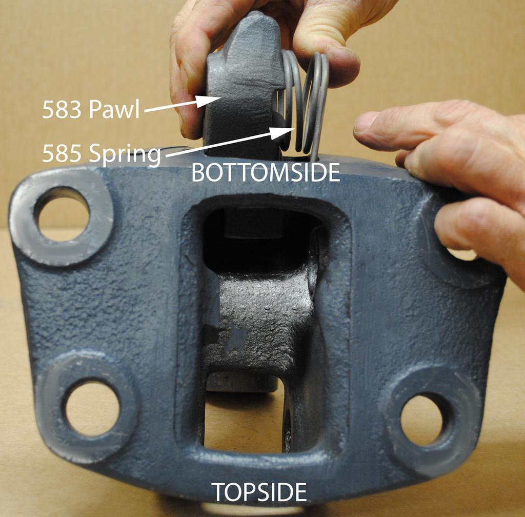
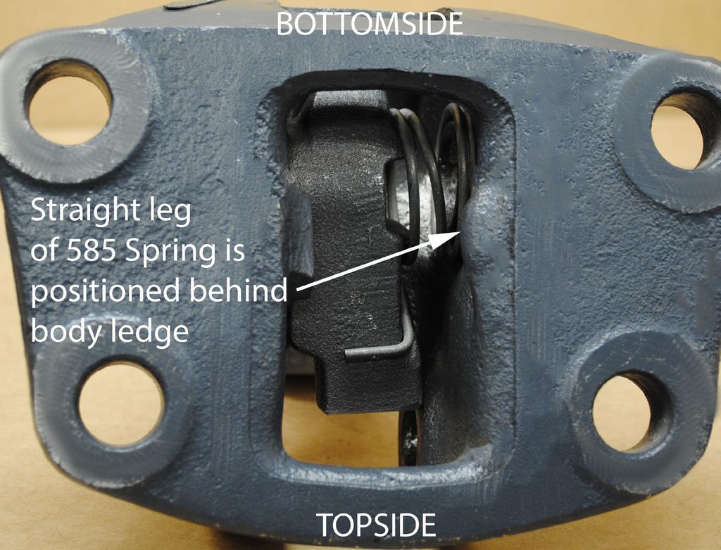
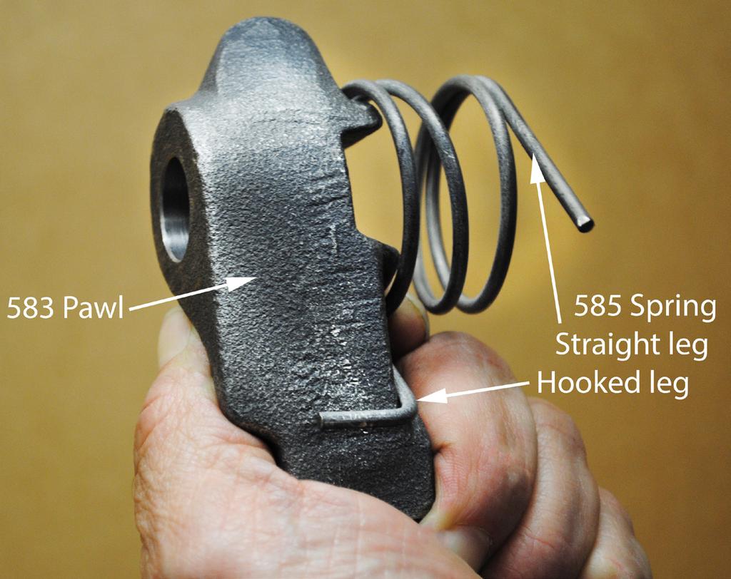
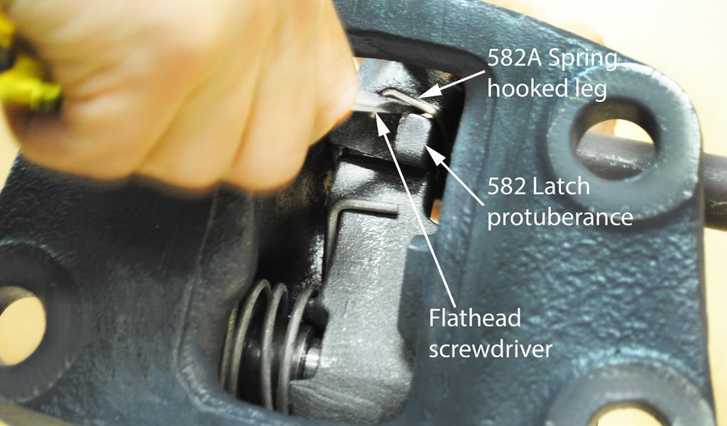
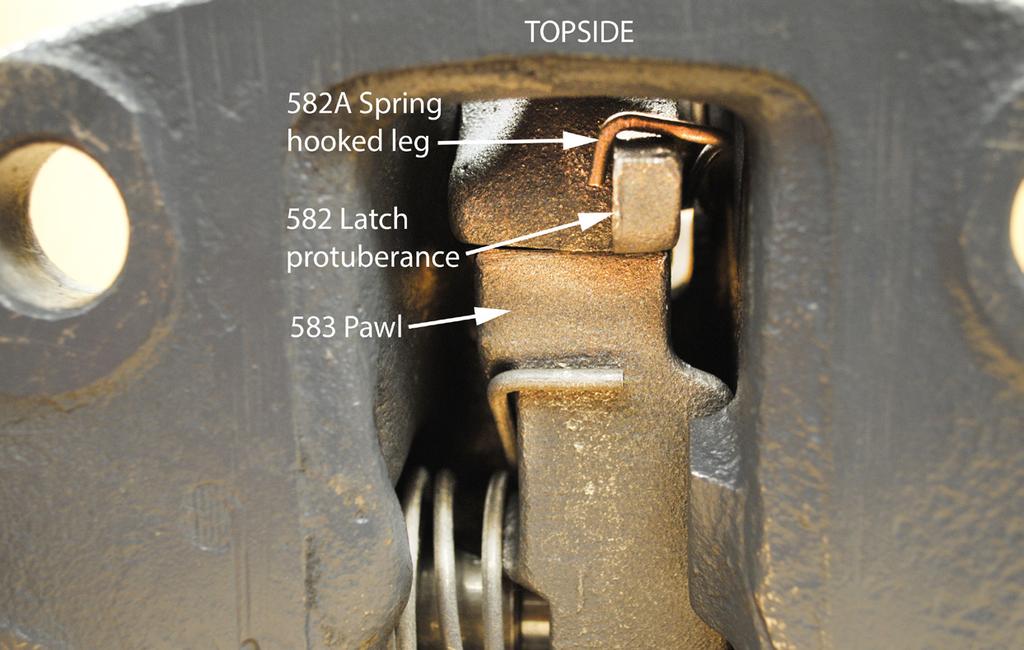
1 580 Coupling THE FIRST NAME IN QUALITY COUPLINGS 580RK SERVICE GUIDELINES For coupling models: 580 & 580J BEFORE GETTING STARTED: This procedure should only be performed by a qualified mechanic. Measure the wear on the coupling s pintle hook. If the wear is at or exceeds 20% of the cross section, the coupling is considered Out of Service. DO NOT continue. Premier has Wear Gages to determine wear on our Couplings and Drawbar Eyes. Examine the entire coupling body for excessive wear or any damage. If any exists, DO NOT continue, coupling needs to be replaced. Tools required: 1 1/4 & 15/16 sockets, flathead screwdriver, adjustable wrench, & soft-faced hammer. Safety glasses are required for all of the following procedures. Note: Use caution when removing and replacing springs. They can eject from the coupling with force. See attached Image Reference Section(s) with photos and/or drawings to identify various parts. See Image #1 for labeled part numbers. Prior to disassembly, familiarize yourself with the location of all the various parts in the coupling. This will assist in the assembly process. DISASSEMBLY 1) The 580 Coupling should be positioned upright with the latch in the closed position (see Image #2 in the Image Reference Section.) 2) Locate the 584 Bolt and remove the 387 Locknut from the right side. Slide the 584 Bolt out from the left side. 3) Remove the 582 Latch and the 582A Spring. 4) Locate the 581A Handle and remove the 375A Locknut and 581BB Clip & Cable, from the left side. 5) Using a soft-faced hammer, tap the 581A Handle squarely on the end to dislodge it from the 583 Pawl and remove it. Note: The 581A Handle can become lodged onto the 583 Pawl and may require penetrating lubricant to be applied, before it will loosen (see Image #3). 6) Position the coupling upside-down so you can reach into the bottom body hole of the coupling and remove the 266 Spring (see Image #4). 7) With the coupling upside-down, position it so that the backside/mounting base is facing you. 8) Using a flathead screwdriver, release the straight leg of the 585 Spring from the internal body ledge (see Image #5). This will reduce the spring tension. 9) Now refer to Image #6 to grab the 583 Pawl and pull it out of the bottom body hole. 10) With all parts removed from the coupling body, clean and inspect the body for wear and/or damage. If wear exists or damage is noted, do not attempt to repair. DO NOT ATTEMPT WELD REPAIR OF ANY DAMAGED AND/OR WORN PART. DISASSEMBLY IS COMPLETE IMPORTANT NOTES TO CLEAN, INSPECT & LUBRICATE: Use only genuine PREMIER replacement parts on any repairs. Use of other parts, which can have different specifications or tolerances, may fail to alert you to non-obvious damage to the hitch which can lead to hitch failure. Clean, inspect and lubricate latch components every 90 days, or sooner if required by the operating environment. Clean and inspect the coupling for damage and excessive wear prior to each and every use. Do not over-tighten fasteners as this may cause damage. PREMIER MANUFACTURING COMPANY Page 1
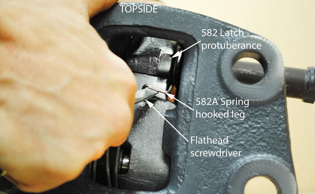
2 ASSEMBLY 1) All body holes, part holes and pins need to be thoroughly cleaned and lubricated with a heavy grease before the parts are reassembled. DO NOT LUBRICATE PINTLE HOOK WEAR SURFACE. 2) Place the 580 Coupling Body upside-down, with the backside/mounting base facing you. 3) Hold the 583 Pawl vertical, with the nipple at the top, and place the 585 Spring onto the 583 Pawl as shown in Image #7. 4) Holding these in position, with the nipple facing away from you, insert and slide the 583 Pawl and 585 Spring in through the bottom of the coupling body (see Image #8). Push in until the holes align. 5) The straight leg of the 585 Spring should slide into position behind the internal body ledge. If not, use a flathead screwdriver to position the straight leg (see Image #9). 6) Slide the 581A Handle into the coupling from the right side, making certain the two tapered handle flats are engaged fully with the 583 Pawl. 7) Rotate the coupling body onto its mounting base and verify that the handle is in the position shown in Image #10. 8) Insert the 581C Bushing onto the left side of the 581A Handle and into the coupling body hole (see Image #10). Note: Make certain the groove in the bushing is towards the outside of the coupling. 9) Place the washer portion of the 581BB Clip & Cable onto the 581A Handle and then secure the handle with the 375A Locknut (see Image #11). Torque to 30 ft-lbs. 10) Take the 266 Spring and insert it through the bottom body hole. Place one end of the spring into the concave portion of the pintle horn base, then slightly compress the spring, placing the other end over the nipple of the 583 Pawl. 11) Reposition the coupling body to the upright sitting position, with the backside/mounting base facing you. 12) Hold the 582A Spring by the hooked leg, in the vertical position, with the straight leg pointing toward you. Insert it through the backside of the coupling, on the right side of the 583 Pawl. Position 582A Spring with hole in body wall (see Image #12). 13) Slide the 584 Bolt partially through the bolt hole, from right side Just far enough to hold the 585 Spring in place (see Image #13). 14) Slide the 582 Latch into the front of the coupling body while looking through the backside, and use a flathead screwdriver to lift the hooked leg of the 582A Spring over the protuberance/knob of the 582 Latch (see Images #14, #15 & #16). 15) Now, simultaneously, use your right hand to push the 584 Bolt to the left and at the same time push down on the top of the coupling with left hand, so that the 581A Handle engages with the counter, causing it to rotate some. 16) This will allow the 582 Latch to fully engage, allowing the 584 Bolt to pass through the latch. 17) Secure the 584 Bolt with the 387 Locknut. Torque to 60 ft-lbs. 18) Once the coupling is assembled it should be opened and closed several times, testing for smooth and correct operation. 19) Place the 581BB Clip onto the groove of the 581C Bushing. Now attempt to open the coupling. If the coupling is assembled properly, the clip will stop against the body sidewall and thus not allow the 581 Handle to rotate into the open position. 20) DO NOT use the coupling if it does not operate properly. Call for assistance. ASSEMBLY IS COMPLETE NOTE: Use only new Grade-8 fasteners torqued to SAE specifications when mounting the assembled coupling to its mounting structure. WARNING: Do NOT bind-up (jackknife) any application, as stresses can cause damage to the hitch, drawbar eye, other components or any combination of them. Jackknifing may result in failure of products or components, resulting in detachment of the trailer while in use. IMPORTANT GUIDELINES that apply to all Premier Non-Air Couplings - Do not weld on any coupling assembly - Always use Grade-8 fasteners properly torqued - Do not apply lubricants to the coupling hook - Clean & inspect coupling for damage & excessive wear prior to each and every use - Lubricate all coupling components at a minimum of 90 day intervals - Do not bind-up (Jackknife) any application as stresses can cause damage to products or components, resulting in failure and detachment of the trailer while in use PREMIER MANUFACTURING COMPANY Page 2


3 IMAGE REFERENCE SECTION IMAGE #1 266: 375A: 387: 581A: 581BB: 581C: 582: 582A: 580RK Parts Kit Includes: 582 Spring Locknut Locknut Handle Clip & Cable Bushing Latch Spring 583: Pawl 584: Bolt 585: Spring *581: Handle Assembly *Available individually *581: Handle Assembly 375A 581C 581A 582A 581BB IMAGE #2 TOPSIDE FRONTSIDE BACKSIDE MOUNTING BASE BOTTOMSIDE IMAGE #3 IMAGE #4 PREMIER MANUFACTURING COMPANY Page 3


4 IMAGE REFERENCE SECTION IMAGE #5 IMAGE IMAGE #8 IMAGE #6 IMAGE #9 IMAGE #7 PREMIER MANUFACTURING COMPANY Page 4


5 IMAGE REFERENCE SECTION IMAGE #10 IMAGE #13 IMAGE #14 IMAGE #11 IMAGE #15 IMAGE #12 IMAGE #16 PREMIER MANUFACTURING COMPANY Page 5
6 CONTINUE TO NEXT PAGE FOR IMPORTANT INFORMATION. PREMIER MANUFACTURING COMPANY Page 6
7 ATTENTION! End Users must read and follow this information. DISTRIBUTORS & OEM S: Please ensure that your customers are made aware of the following information on this page. (1) VERIFY THAT BOTH COUPLING S AND DRAWBAR EYE S RATED CAPACITIES MEET YOUR APPLICATION(S) REQUIREMENTS. (2) DO NOT OVERLOAD COUPLING OR DRAWBAR EYE. (3) INSPECT COUPLING, LATCH AND DRAWBAR EYE FOR CRACKS, BENDING DAMAGE OR EXCESSIVE WEAR. DO NOT USE IF ANY OF THESE CONDITIONS EXIST! (4) CHECK FOR GAP BETWEEN CLOSED LATCH AND TOP OF HORN OR COUPLING BALL. DO NOT USE IF GAP IS 3/8 IN. OR MORE. (5) MAKE SURE COUPLING IS LATCHED AND THAT LATCH WILL NOT OPEN. (6) PRIOR TO USE, ALWAYS CONNECT SAFETY CHAINS OF ADEQUATE STRENGTH FOR LOAD(S) BEING TOWED. (7) DO NOT BIND-UP (JACKKNIFE) ANY APPLICATION AS STRESSES CAN CAUSE DAMAGE TO THE COUPLING, DRAWBAR EYE, OTHER COMPONENTS OR ANY COMBINATION OF THEM. JACKKNIFING MAY RESULT IN FAILURE OF PRODUCTS OR COMPONENTS, RESULTING IN DETACHMENT OF THE TRAILER WHILE IN USE. (8) DO NOT APPLY LUBRICANTS TO THE COUPLING HOOK OR DRAWBAR EYE LOOP, AS THEY CAN COVER UP POSSIBLE DAMAGE AND ACCELERATE WEAR. (9) ALWAYS ABIDE BY ALL APPLICABLE STATE AND FEDERAL REGULATIONS GOVERNING SAFE AND PROPER TRANSPORTATION. (10) NEVER STRIKE ANY OF THESE COMPONENTS WITH A HAMMER OR ANY OTHER DEVICE. (11) ALWAYS VERIFY PROPER OPERATION OF LATCHING SYSTEM AND COUPLING COMPONENTS PRIOR TO DRIVE OFF. (12) NEVER USE A COUPLING THAT YOU DO NOT FULLY UNDERSTAND HOW TO PROPERLY OPERATE AND VERIFY SECURE LATCHING OF. (13) NEVER REPLACE ANY PART IN ANY OF PREMIER S ASSEMBLIES WITH NON-PREMIER COMPONENTS. DOING SO WILL VOID ALL WARRANTY AND POTENTIALLY COMPROMISE THE UNIT S INTEGRITY, WHICH COULD RESULT IN PROPERTY DAMAGE, SERIOUS INJURY, OR DEATH. PREMIER MANUFACTURING COMPANY Page 7
8 WARNING! Important Installation Instructions: Do NOT attempt install without first reading all attached instructions. Installation must be performed by a qualified mechanic only. PREMIER MANUFACTURING COMPANY THE FIRST NAME IN QUALITY COUPLINGS (503) RK Service Guidelines 01/2013 WARRANTY: We warrant all Premier products to be free from defects in material or workmanship for one year. We will repair or replace, at our option, any Premier product which our examination reveals to be defective, provided that the product is returned to our factory, at Tualatin, Oregon transportation prepaid, within one year of purchase by the first retail purchaser. Our warranty does not extend to products which have been subject to misuse, neglect, improper installation, maintenance or application, nor does our warranty extend to products which have been repaired or altered outside of Premier s facility unless the repair or alteration has been expressly authorized in writing by Premier. This warranty is in lieu of all other warranties, express or implied, and excludes warranties of merchantability, fitness for a particular purpose and otherwise, and in no event will Premier be liable for incidental, special, contingent or consequential damages. DISCLAIMER: Although great care has been taken to ensure accurate information throughout this document, Premier Manufacturing Company must reserve the right to alter any information contained within. These changes include but are not limited to: Dimensional changes, load capacity and availability of any part or assembly Premier Manufacturing Company All rights reserved. Any reproduction of the photographic images or any other portion of this document, including but not limited to the photocopying, or retention and/or storage in a retrieval system of any kind, is strictly prohibited without prior express written permission from Premier Manufacturing Company. PREMIER MANUFACTURING COMPANY Page 8
270PK SERVICE GUIDELINES
 270 Coupling THE FIRST NAME IN QUALITY COUPLINGS 270PK SERVICE GUIDELINES BEFORE GETTING STARTED: This procedure should only be performed by a qualified mechanic. Measure the wear on the coupling s pintle
Model 580 / 580J Coupling
 MANUFACTURING CO. THE FIRST NAME IN QUALITY COUPLINGS Installation, Inspection, Operation & Maintenance Guide Model 580 / 580J Coupling IMPORTANT Read these instructions completely before installing, using
Model 240K / 240KL Coupling
 MANUFACTURING CO. THE FIRST NAME IN QUALITY COUPLINGS Installation, Inspection, Operation & Maintenance Guide Model 240K / 240KL Coupling IMPORTANT Read these instructions completely before installing,
Model 407SE Swivel Drawbar Eye
 MANUFACTURING CO. THE FIRST NAME IN QUALITY COUPLINGS Installation, Inspection, Operation & Maintenance Guide Model 407SE Swivel Drawbar Eye IMPORTANT Read these instructions completely before installing,
Saf-Tite Coupling
 MANUFACTURING CO. THE FIRST NAME IN QUALITY COUPLINGS Installation, Inspection, Operation & Maintenance Guide Raising the Bar SAF TITE Strength & Value Saf-Tite 100-3 Coupling IMPORTANT Read these instructions
Model 6 Weld-On Drawbar Eye
 MANUFACTURING CO. THE FIRST NAME IN QUALITY COUPLINGS Installation, Inspection, Operation & Maintenance Guide Model 6 Weld-On Drawbar Eye IMPORTANT Read these instructions completely before installing,
Saf-Tite / 100-4H Coupling
 MANUFACTURING CO. THE FIRST NAME IN QUALITY COUPLINGS Installation, Inspection, Operation & Maintenance Guide Raising the Bar SAF TITE Strength & Value Saf-Tite 100-4 / 100-4H Coupling IMPORTANT Read these
MANUFACTURING CO. THE FIRST NAME IN QUALITY COUPLINGS. Installation, Inspection, Operation & Maintenance Guide. Model 150 Coupling IMPORTANT
 MANUFACTURING CO. THE FIRST NAME IN QUALITY COUPLINGS Installation, Inspection, Operation & Maintenance Guide Model 150 Coupling IMPORTANT Read these instructions completely before installing, using or
Model 2200ELL Coupling
 MANUFACTURING CO. THE FIRST NAME IN QUALITY COUPLINGS Installation, Inspection, Operation & Maintenance Guide Model 2200ELL Coupling IMPORTANT Read these instructions completely before installing, using
Model 123 Weld-On Adjustable Drawbar Eye
 MANUFACTURING CO. THE FIRST NAME IN QUALITY COUPLINGS Installation, Inspection, Operation & Maintenance Guide Model 123 Weld-On Adjustable Drawbar Eye IMPORTANT Read these instructions completely before
Model 330 / 330A Hinge Assembly
 MANUFACTURING CO. THE FIRST NAME IN QUALITY COUPLINGS Installation, Inspection, Operation & Maintenance Guide Model 330 / 330A Hinge Assembly IMPORTANT Read these instructions completely before installing,
MANUFACTURING CO. THE FIRST NAME IN QUALITY COUPLINGS. Installation, Inspection, Operation & Maintenance Guide. Model 880 Coupling IMPORTANT
 MANUFACTURING CO. THE FIRST NAME IN QUALITY COUPLINGS Installation, Inspection, Operation & Maintenance Guide Model 880 Coupling IMPORTANT Read these instructions completely before installing, using or
Model 690L / 690R / 690T Coupling
 MANUFACTURING CO. THE FIRST NAME IN QUALITY COUPLINGS Installation, Inspection, Operation & Maintenance Guide Model 690L / 690R / 690T Coupling IMPORTANT Read these instructions completely before installing,
Model 580 / 580J Coupling
 MANUFACTURING CO. THE FIRST NAME IN QUALITY COUPLINGS Installation, Inspection, Operation & Maintenance Guide Model 580 / 580J Coupling IMPORTANT Read these instructions completely before installing, using
Model 470 / 470H Coupling
 MANUFACTURING CO. THE FIRST NAME IN QUALITY COUPLINGS Installation, Inspection, Operation & Maintenance Guide 470 470H Model 470 / 470H Coupling IMPORTANT Read these instructions completely before installing,
Model 240K / 240KL Coupling
 MANUFACTURING CO. THE FIRST NAME IN QUALITY COUPLINGS Installation, Inspection, Operation & Maintenance Guide Model 240K / 240KL Coupling IMPORTANT Read these instructions completely before installing,
Installation, Inspection, Operation & Maintenance Guide
 MANUFACTURING CO. THE FIRST NAME IN QUALITY COUPLINGS Installation, Inspection, Operation & Maintenance Guide 238DB, 245DB & 245DB-3 Bolt-On Drawbar Eyes IMPORTANT Read these instructions completely before
Model 320 / 320A Hinge Assembly
 MANUFACTURING CO. THE FIRST NAME IN QUALITY COUPLINGS Installation, Inspection, Operation & Maintenance Guide Model 320 / 320A Hinge Assembly IMPORTANT Read these instructions completely before installing,
Low Profile Service Jack Jack Stand Combo
 Low Profile Service Jack Jack Stand Combo Jack Stands Low Profile Service Jack U.S. Patent No. 6,199,379! This is the safety alert symbol. It is used to alert you to potential personal injury hazards.
Auto-Locking Pintle Hook
 Auto-Locking Pintle Hook 7-Ton Capacity Owner s Manual WARNING: Read carefully and understand all ASSEMBLY AND OPERATION INSTRUCTIONS before operating. Failure to follow the safety rules and other basic
16K and 19K Sidewinder TM Service Kit Instructions 86005
 86005 Equipment Required: Wrenches: 15/16, 1 1/8, Torque Wrench, Rubber Mallet Included Service Kit Items: 1 Qty. (1) Wear Plate 2 Qty. (6) 5/8 Conical Washer 3 Qty. (2) Wedge Bolt, 5/8-11 X 1 3/4 GRD
MODEL 7400 STRUT SPRING COMPRESSOR
 MODEL 7400 STRUT SPRING COMPRESSOR Installation, Operation & Repair Parts Information Branick Industries, Inc. 4245 Main Avenue P.O. Box 1937 Fargo, North Dakota 58103 REV112712 P/N: 81-0103A TABLE OF
16K Revolution Service Kit Instructions 86016
 86016 Equipment Required: Wrenches: 15/16, 1 1/8, Torque Wrench, Rubber Mallet Included Service Kit Items: 1 Qty. (1) Wear Plate 2 Qty. (1) Pivot Bushing 3 Qty. (1) Bearing Cup 4 Qty. (1) Bearing 1 5 Qty.
6-TON DOUBLE LOCKING JACK STANDS OWNER S MANUAL
 6-TON DOUBLE LOCKING JACK STANDS OWNER S MANUAL WARNING: Read carefully and understand all ASSEMBLY AND OPERATION INSTRUCTIONS before operating. Failure to follow the safety rules and other basic safety
Please visit for the latest version of these installation instructions.
 Please visit www.blueox.com for the latest version of these installation instructions. Attachment Tab Height: 19-1/2 Serial Number Attachment Tab Width: 19 Please read BOTH these and the General Information
INSTALLATION INSTRUCTIONS
 08 YEARS: 07-CURRENT Safety glasses should be worn at all times while installing this product. INSTALLATION INSTRUCTIONS MODEL: RIDGELINE MAKE: HONDA STYLE: TRUCK WARNING: NEVER EXCEED YOUR VEHICLE MANUFACTURER'S
BX7322 Adventurer Tow Bar Operator Manual & Installation Instructions
 Please visit www.blueox.com for the latest version of these installation instructions. BX7322 Operator Manual & Installation Instructions Serial Number (5,000 lb) 2 Inch Coupler 292-1263 Rev J Page 1 of
Please visit for the latest version of these installation instructions.
 Please visit www.blueox.com for the latest version of these installation instructions. 2014-2017 Ram 2500 (All beds) Please read these in their entirety prior to installing or operating this equipment.
Please visit for the latest version of these installation instructions.
 Please visit www.blueox.com for the latest version of these installation instructions. 2011-16 Mini Cooper Countryman (Includes S) Attachment Tab Height: 14 Serial Number Attachment Tab Width: 20 Please
BX7322 Adventurer Tow Bar Operator Manual & Installation Instructions
 Please visit www.blueox.com for the latest version of these installation instructions. BX7322 Operator Manual & Installation Instructions Serial Number (5,000 lb) 2 Inch Coupler 292-1263 Rev J Page 1 of
BX4330 Acclaim Tow Bar Operator Manual & Installation Instructions
 Please visit www.blueox.com for the latest version of these installation instructions. BX4330 Operator Manual & Installation Instructions Serial Number (5,000 lb) 2 Inch Coupler 292-2205 Rev L Page 1 of
MODEL 7600 STRUT SPRING COMPRESSOR
 MODEL 7600 STRUT SPRING COMPRESSOR Installation, Operation & Repair Parts Information Branick Industries, Inc. 4245 Main Avenue P.O. Box 1937 Fargo, North Dakota 58103 REV6162014 P/N: 81-0246 TABLE OF
3-TON DOUBLE LOCKING JACK STANDS OWNER S MANUAL
 3-TON DOUBLE LOCKING JACK STANDS OWNER S MANUAL WARNING: Read carefully and understand all ASSEMBLY AND OPERATION INSTRUCTIONS before operating. Failure to follow the safety rules and other basic safety
WARNING: NEVER EXCEED YOUR VEHICLE MANUFACTURER'S RECOMMENDED TOWING CAPACITY LBS. LBS.
 05 INSTALLATION INSTRUCTIONS Safety glasses should be worn at all times while installing this product. YEARS: 009-0 MAKE: CHEVROLET, BUICK & GMC MODEL: TRAVERSE, ENCLAVE & ACADIA STYLE: CROSSOVER WARNING:
5 th Airborne Sidewinder Service Kit Instructions 94316
 94316 Equipment Required: Wrenches: 15/16, Torque Wrench, Rubber Mallet 3 4 5 2 Included Service Kit Items: 1 Qty. (1) Wear Plate 2 Qty. (1) Wear Bushing 3 Qty. (1) Wear Disc 4 Qty. (4) 5/8-11x2 GRD8 Bolt
Operating Instructions & Parts Manual
 Aluminum / Steel Hybrid Service Jack Operating Instructions & Parts Manual Model 26017 26028 26033 Capacity 1.5 Ton 2.5 Ton 3 Ton! This is the safety alert symbol. It is used to alert you to potential
BX7445 Aventa LX Tow Bar Operator Manual & Installation Instructions
 Please visit www.blueox.com for the latest version of these installation instructions. BX7445 Operator Manual & Installation Instructions Serial Number (10,000 lb) 2 Inch Receiver 292-2938 Rev D Page 1
Please visit for the latest version of these installation instructions.
 Please visit www.blueox.com for the latest version of these installation instructions. Attachment Tab Height: 24-1/2 BX2675 (Incudes Super Duty & ACC) Serial Number Attachment Tab Width: 34-1/2 Please
Please visit for the latest version of these installation instructions.
 Please visit www.blueox.com for the latest version of these installation instructions. BX2643 Please read BOTH these and the General Instructions prior to installing or operating this equipment. 1. Blue
BX Jeep Liberty Renegade 2012 Jeep Liberty Sport Installation Instructions
 Attachment Tab Height: 17.5 Attachment Tab Width: 24 Serial Number Please read BOTH these and the General Instructions prior to installing or operating this equipment. 1. Blue Ox towing products and accessories
Please visit for the latest version of these installation instructions.
 Please visit www.blueox.com for the latest version of these installation instructions. 2013-18 Ford C-Max (Includes Hybrid & Energi) Attachment Tab Height: 12 Serial Number Attachment Tab Width: 20 Please
Low Profile Service Jack
 Low Profile Service Jack Model GMG29031 Capacity 3 Ton U.S. Patent No. 6,199,379! This is the safety alert symbol. It is used to alert you to potential personal injury hazards. Obey all safety messages
KENCOVE PD100 MANUAL TILT POST DRIVER
 OPERATOR S MANUAL KENCOVE PD100 MANUAL TILT POST DRIVER WWW.KENCOVE.COM 800-536-2683 344 KENDALL RD, BLAIRSVILLE, PA 15717 Table of Contents Specifications/Requirements 1 Introduction 2 Equipment Inspection
Operator s Manual. Nitro 1000 Nitro 1000X. Nitro 750 Nitro 750X. September REV0
 Operator s Manual Nitro 750 Nitro 750X Nitro 1000 Nitro 1000X September.27.2018REV0 Table of Contents Introduction...3 Safety.....4 Equipment Requirements......5 What You Have Received. 5 Serial Number...6
Please visit for the latest version of these installation instructions.
 Please visit www.blueox.com for the latest version of these installation instructions. DH2400 (Long & Standard Box) Please read these in their entirety prior to installing or operating this equipment.
Please visit for the latest version of these installation instructions.
 Please visit www.blueox.com for the latest version of these installation instructions. Attachment Tab Height: 18 Serial Number Attachment Tab Width: 18 Please read BOTH these and the General Information
12158 INSTALLATION INSTRUCTIONS
 5 INSTALLATION INSTRUCTIONS Safety glasses should be worn at all times while installing this product. YEARS: 07-CURRENT MAKE: KIA MODEL: SPORTAGE STYLE: SUV WARNING: NEVER EXCEED YOUR VEHICLE MANUFACTURER'S
31034 INSTALLATION INSTRUCTIONS
 0 INSTALLATION INSTRUCTIONS Safety glasses should be worn at all times while installing this product. YEARS: 00-PRESENT MAKE: HYUNDAI MODEL: SANTA FE STYLE: SUV WARNING: NEVER EXCEED YOUR VEHICLE MANUFACTURER'S
Please visit for the latest version of these installation instructions.
 Please visit www.blueox.com for the latest version of these installation instructions. BX1726 (All Models) (No Active Shutters or E-Assist) Attachment Tab Height: 12 Serial Number Attachment Tab Width:
Please visit for the latest version of these installation instructions.
 Please visit www.blueox.com for the latest version of these installation instructions. BX2409 2009-18 Dodge Ram 1500 Sport/ST/Laramie Limited Please read BOTH these and the General Information sheet prior
MLS KICK-OFF TABLETOP SOCCER TABLE ASSEMBLY INSTRUCTIONS
 MLS KICK-OFF TABLETOP SOCCER TABLE ASSEMBLY INSTRUCTIONS NGD1028 1 THANK YOU! Thank you for your purchase of this Harvil product. We work around the clock and around the globe to ensure that Harvil products
Please visit for the latest version of these installation instructions.
 Please visit www.blueox.com for the latest version of these installation instructions. Attachment Tab Height: 16.5 Serial Number Attachment Tab Width: 30.5 Please read BOTH these and the General Information
Please visit for the latest version of these installation instructions.
 Please visit www.blueox.com for the latest version of these installation instructions. 2015-18 Ford Edge (Includes ACC) (No 2.0L EcoBoost or Sport) Attachment Tab Height: 15 Serial Number Attachment Tab
Operating Instructions & Parts Manual. Fuel Tank Adapter
 Operating Instructions & Parts Manual Fuel Tank Adapter Model Number 40080 Capacity 80 lb.! This is the safety alert symbol. It is used to alert you to potential personal injury hazards. Obey all safety
Please visit for the latest version of these installation instructions.
 Please visit www.blueox.com for the latest version of these installation instructions. BX3796 Attachment Tab Height: 13-1/2 Serial Number Attachment Tab Width: 24 Please read BOTH these and the General
31075 INSTALLATION INSTRUCTIONS
 075 INSTALLATION INSTRUCTIONS Safety glasses should be worn at all times while installing this product. YEARS: 06-PRESENT MAKE: TOYOTA MODEL: TACOMA STYLE: PICKUP WARNING: NEVER EXCEED YOUR VEHICLE MANUFACTURER'S
31015 INSTALLATION INSTRUCTIONS
 0 INSTALLATION INSTRUCTIONS Safety glasses should be worn at all times while installing this product. YEARS: 00-CURRENT MAKE: DODGE RAM MODEL: 00 STYLE: TRUCK WARNING: NEVER EXCEED YOUR VEHICLE MANUFACTURER'S
Please visit for the latest version of these installation instructions.
 Please visit www.blueox.com for the latest version of these installation instructions. BX2414 2019 Ram 1500 (Includes Rebel) (No Classic) Attachment Tab Height: 17 Serial Number Attachment Tab Width: 38.5
Please read BOTH these Installation Instructions and the General Information sheet prior to installing or operating this equipment.
 Attachment Tab Height: 24-1/4 Serial Number Attachment Tab Width: 24 Please read BOTH these and the General Information sheet prior to installing or operating this equipment. 1. Blue Ox towing products
Please visit for the latest version of these installation instructions.
 Please visit www.blueox.com for the latest version of these installation instructions. BX1126 Attachment Tab Height: 14-1/2 Serial Number Attachment Tab Width: 24 Please read BOTH these and the General
INSTALLATION INSTRUCTIONS
 INSTALLATION INSTRUCTIONS Thank you for purchasing a LOMAX TM Hard Tri-Fold or Professional Series Cover. Agri-Cover, Inc. proudly manufactured this cover using superior quality materials and workmanship.
Please visit for the latest version of these installation instructions.
 Please visit www.blueox.com for the latest version of these installation instructions. Attachment Tab Height: 16 Serial Number Attachment Tab Width: 35 Please read BOTH these and the General Information
3 TON JACK STANDS. Operator s Instruction Manual. Rated Capacity 6,000-lb MODEL# T43002T
 Operator s Instruction Manual 3 TON JACK STANDS Rated Capacity 6,000-lb MODEL# T43002T This is the Safety Alert Symbol. It is used to alert you to potential personal injury hazards. Obey all safety messages
Please visit for the latest version of these installation instructions.
 Please visit www.blueox.com for the latest version of these installation instructions. BX3623 2017-19 Subaru Impreza (Manual) (No Fog Lights) Attachment Tab Height: 13 Serial Number Attachment Tab Width:
Please visit for the latest version of these installation instructions.
 Please visit www.blueox.com for the latest version of these installation instructions. Attachment Tab Height: 21 Serial Number Attachment Tab Width: 31.25 Please read BOTH these and the General Information
Installation Manual. Uniball Upper Control Arm Kit Toyota Tacoma 4x Toyota 4Runner 4x Toyota Tundra 4x4 Part # 50965
 Part # 50965 Uniball upper control arm kit Part # Description Qty. 50965-01 Driver side upper control arm 1 50965-02 Passenger side upper control arm 1 50965-03 Driver side knuckle support bracket 1 50965-04
31087 INSTALLATION INSTRUCTIONS
 31087 INSTALLATION INSTRUCTIONS Safety glasses should be worn at all times while installing this product. YEARS: 019-PRESENT MAKE: RAM MODEL: 1500 STYLE: TRUCK WARNING: NEVER EXCEED YOUR VEHICLE MANUFACTURER'S
Please visit for the latest version of these installation instructions.
 Please visit www.blueox.com for the latest version of these installation instructions. 2012-17 Chevy Sonic (LS/LT/LTZ/RS) Attachment Tab Height: 13-1/2 Serial Number Attachment Tab Width: 18 Please read
SIDE-WIND, A-FRAME TRAILER JACK. Model Due to continuing improvements, actual product may differ slightly from the product described herein.
 SIDE-WIND, A-FRAME TRAILER JACK Model 95157 Assembly And Operation Instructions Due to continuing improvements, actual product may differ slightly from the product described herein. 3491 Mission Oaks Blvd.,
Please visit for the latest version of these installation instructions.
 Please visit www.blueox.com for the latest version of these installation instructions. Attachment Tab Height: 15-1/2 Serial Number Attachment Tab Width: 24 Please read BOTH these and the General Information
3-Pt. Quick Hitch. Owner s Manual
 3-Pt. Quick Hitch Owner s Manual WARNING: Read carefully and understand all ASSEMBLY AND OPERATION INSTRUCTIONS before operating. Failure to follow the safety rules and other basic safety precautions may
Hydraulic Wheel Dolly
 Hydraulic Wheel Dolly Operating Instructions & Parts Manual Model Number HW93765 Capacity 3/4 Ton Made in the U.S.A. This is the safety alert symbol. It is used to alert you to potential personal injury
Fast Lift Service Jack, Low Profile
 Blackhawk Automotive is a Licensed Trade Mark Made by SFA Companies, Kansas City, MO Fast Lift Service Jack, Low Profile Operating Instructions & Parts Manual Model BH6023B Capacity 2 Ton! U.S. Patent
BX1681. Please read BOTH these Installation Instructions and the General Towing Instructions before attempting to install or operate this equipment.
 Serial Number BX1681 2007-13 Chevy Pickup 1500, 2500 & 3500 New Style Heavy Duty (2WD/4WD), 2007-11 GMC Pickup 2500 & 3500 New Style, 2008-10 GMC Yukon 2500 Please read BOTH these and the General Towing
Auto-Locking Trailer Coupler
 Auto-Locking Trailer Coupler 7-Ton Capacity Owner s Manual WARNING: Read carefully and understand all ASSEMBLY AND OPERATION INSTRUCTIONS before operating. Failure to follow the safety rules and other
Please visit for the latest version of these installation instructions.
 Please visit www.blueox.com for the latest version of these installation instructions. BX2625 2011-15 Lincoln MKX (includes Adaptive Cruise Control) Attachment Tab Height: 18-1/4 Attachment Tab Width:
Please visit for the latest version of these installation instructions.
 Please visit www.blueox.com for the latest version of these installation instructions. BX1730 Attachment Tab Height: 16 Serial Number Attachment Tab Width: 23 Please read BOTH these and the General Information
Please visit for the latest version of these installation instructions.
 Please visit www.blueox.com for the latest version of these installation instructions. BX2412 2016-18 Ram 1500 Rebel 2016-18 Ram 1500 Bighorn/Laramie/Laramie Longhorn (Chrome Bumpers) 2018 Ram 1500 (Metal
31025 INSTALLATION INSTRUCTIONS
 105 INSTALLATION INSTRUCTIONS Safety glasses should be worn at all times while installing this product. YEARS: 011 MAKE: FORD, MERCURY MODEL: ESCAPE, MARINER STYLE: SUV WARNING: NEVER EXCEED YOUR VEHICLE
TECHNICAL SERVICE MANUAL
 Electronic copies of the most current TSM issue can be found on the Viking Pump website at www.vikingcom TECHNICAL SERVICE MANUAL abrasive liquid pumps SERIES 4625 SIZES f - fh SECTION TSM 410.1 PAGE 1
PRODUCT OBSOLETED 4Q16
 Electronic copies of the most current TSM issue can be found on the Viking Pump website at www.vikingcom TECHNICAL SERVICE MANUAL abrasive liquid pumps SERIES 4625 SIZES f - fh SECTION TSM 410.1 PAGE 1
Operating Instructions & Parts Manual
 Swift Lift Hydraulic Service Jack Operating Instructions & Parts Manual Model Number ATD7341 Capacity 3-1/2 Ton U.S. Patent No's. 5,946,912 6,199,379! This is the safety alert symbol. It is used to alert
Please visit for the latest version of these installation instructions.
 Please visit www.blueox.com for the latest version of these installation instructions. BX1139 2018 Jeep Wrangler / Wrangler Unlimited (JL) (All Models w/standard Bumper) Attachment Tab Height: 18 Serial
31065 INSTALLATION INSTRUCTIONS
 106 INSTALLATION INSTRUCTIONS Safety glasses should be worn at all times while installing this product. YEARS: 010-PRESENT MAKE: DODGE MODEL: RAM 00 STYLE: PICKUP WARNING: NEVER EXCEED YOUR VEHICLE MANUFACTURER'S
1000-LB. MOTORCYCLE LIFT TABLE OWNER S MANUAL
 1000-LB. MOTORCYCLE LIFT TABLE OWNER S MANUAL WARNING: Read carefully and understand all ASSEMBLY AND OPERATION INSTRUCTIONS before operating. Failure to follow the safety rules and other basic safety
WARNING. BX Buick Lacrosse Installation Instructions. Bolt Torque Specifications. Bolt Torque Specifications
 Please read BOTH these and the General Instructions before attempting to install or operate this equipment. 1. Blue Ox towing products and accessories are intended to be installed by Blue Ox Dealers who
31056 INSTALLATION INSTRUCTIONS
 305 INSTALLATION INSTRUCTIONS Safety glasses should be worn at all times while installing this product. YEARS: 00-00 MAKE: JEEP MODEL: COMMANDER STYLE: SUV WARNING: NEVER EXCEED YOUR VEHICLE MANUFACTURER'S
Please visit for the latest version of these installation instructions.
 Please visit www.blueox.com for the latest version of these installation instructions. BX1715 2014-15 Chevy Malibu (All Models) 2016 Chevy Malibu Limited (No Active Shutter or E-Assist) Attachment Tab
Please visit for the latest version of these installation instructions.
 Please visit www.blueox.com for the latest version of these installation instructions. BX1138 2014-18 Jeep Cherokee (No Trailhawk) (Includes Adaptive Cruise) Attachment Tab Height: 19-1/2 Serial Number
Please visit for the latest version of these installation instructions.
 Please visit www.blueox.com for the latest version of these installation instructions. BX1718 2015-18 Chevy Suburban/Tahoe 2015-18 GMC Yukon/Yukon XL (Includes Denali) Please read BOTH these and the General
1000-LB. ENGINE STAND
 1000-LB. ENGINE STAND WARNING: Read carefully and understand all ASSEMBLY AND OPERATION INSTRUCTIONS before operating. Failure to follow the safety rules and other basic safety precautions may result in
Please visit for the latest version of these installation instructions.
 Please visit www.blueox.com for the latest version of these installation instructions. BX1690 Attachment Tab Height: 16-1/2 Serial Number Attachment Tab Width: 18 Please read BOTH these and the General
Installation Instructions GOOSENECK MOUNTING KIT Toyota Tundra
 GOOSENECK MOUNTING KIT Toyota Tundra 446 Equipment Required: Fastener Kit: 446F Wrenches: 10mm, 1mm, /4, 7/8, 15/16 Drill Bits: 1/4 Other Tools: Drill WARNING: Do not store hitch ball upside down in head.
Electromagnetic Particle Brakes Model: PRB-H
 P-223-3 819-0370 Electromagnetic Particle Brakes Model: PRB-H Installation Instructions Table of Contents Introduction............................2 Installation Instructions....................3 Start
SPECIFICATIONS GENERAL SAFETY RULES PERSONAL SAFETY. Save This Manual TOOL USE AND CARE WORK AREA
 SPECIFICATIONS 2 Forged Safety Latch Hooks Cable extends to: 44 Drop forged steel hanging bracket Heavy duty 3/16 Steel Cable Pulling Capacity: 1200 LB. One piece double ratchet gear Save This Manual You
ULTRA WEIGHT DISTRIBUTING HITCH SYSTEM INSTALLATION/OPERATION INSTRUCTIONS
 ULTRA-FAB PRODUCTS, INC. 57985 St. Rd. 19 South, Elkhart, Indiana 46517 ULTRA WEIGHT DISTRIBUTING HITCH SYSTEM ULTRA WEIGHT DISTRIBUTING HITCH SYSTEM INSTALLATION/OPERATION INSTRUCTIONS ITEM # 1 EXPLODED
INSTALLATION INSTRUCTIONS AND OWNER S MANUAL
 INSTALLATION INSTRUCTIONS AND OWNER S MANUAL Thank you for purchasing the AlloyCover from WeatherTech. Manufactured with pride using superior quality materials and workmanship. With proper care, your cover
11424 INSTALLATION INSTRUCTIONS
 INSTALLATION INSTRUCTIONS Safety glasses should be worn at all times while installing this product. YEARS: 0-CURRENT MAKE: HYUNDAI MODEL: ELANTRA STYLE: SEDAN WARNING: NEVER EXCEED YOUR VEHICLE MANUFACTURER'S
31068 INSTALLATION INSTRUCTIONS
 0 INSTALLATION INSTRUCTIONS Safety glasses should be worn at all times while installing this product. YEARS: 009-CURRENT MAKE: FORD MODEL: F-0 STYLE: ALL WARNING: NEVER EXCEED YOUR VEHICLE MANUFACTURER'S
HEAVY-DUTY STEEL WAGON
 HEAVY-DUTY STEEL WAGON Owner s Manual WARNING: Read carefully and understand all ASSEMBLY AND OPERATION INSTRUCTIONS before operating. Failure to follow the safety rules and other basic safety precautions