MANUFACTURING CO. THE FIRST NAME IN QUALITY COUPLINGS. Installation, Inspection, Operation & Maintenance Guide. Model 880 Coupling IMPORTANT
|
|
|
- Leslie George
- 5 years ago
- Views:
Transcription


1 MANUFACTURING CO. THE FIRST NAME IN QUALITY COUPLINGS Installation, Inspection, Operation & Maintenance Guide Model 880 Coupling IMPORTANT Read these instructions completely before installing, using or attempting to repair this product.
2 Selecting The Right Equipment Whatever your application, selecting the proper equipment for the job is very important. Proper selection along with regular inspection and maintenance will help keep operating costs minimal while providing long life to each component. Below are general guidelines for selecting Premier Couplings and Drawbar Eyes. Follow these four steps to ensure proper selection of Premier Couplings and Drawbar Eyes. Step 1: Determine Gross Trailer(s) Weight (GVWR(s) of towed trailers) Step 2: Determine Tongue Weight Capacity (Maximum occurring tongue weight) Step 3: Add Margin of Safety (Dependent upon your equipment and operating environment) Step 4: Browse Premier Product Catalog (Based on Steps 1-3) Step 1: Determine Gross Trailer(s) Weight Gross Trailer(s) Weight is usually determined by the Gross Vehicle Weight Rating (GVWR). This information is attached to the trailer by the trailer manufacturer. Double Trailer Configuration 40,000 LBS Example only, each application may vary and should be considered unique. Triple Trailer Configuration 40,000 LBS 40,000 LBS Example only, each application may vary and should be considered unique. Step 2: Determine Tongue Weight Capacity For Double Trailer configurations, only the rear trailer is considered when selecting your Premier Coupling or Drawbar Eye. In this example, a Coupling and Drawbar Eye with a Gross Trailer Weight rating of 40,000 lbs. (18,143 kg) would be the minimum rating acceptable for normal, over-theroad applications (see Tongue Weight section below). For Triple Trailers, only the two most rearward trailers are considered in selecting your Premier Coupling or Drawbar Eye. In this example, a Coupling and Drawbar Eye with a Gross Trailer Weight rating of 80,000 lbs. (36,287 kg) would be the minimum acceptable for normal, over-the-road applications (see Tongue Weight section below). Tongue Weight Capacity is the maximum expected weight at the drawbar eye. If a hinged drawbar is used, the maximum weight will be approximately 1/2 the overall drawbar weight. If a non-hinged drawbar is used and the actual tongue weight is not known, you can approximate the weight by multiplying the GVWR of the towed trailer by 15%. However, each application is unique and the best practice is to weigh the tongue when the trailer is loaded to its GVWR. Step 3: Considering Operating Conditions and Environments Environments such as rough uneven roads or off-road use can dramatically increase shock loads to both drawbar eyes and couplings. In general, increasing the Gross Trailer Weight (Step 1:) and Tongue Weight Capacity (Step 2:) by a minimum of 25% will be sufficient for many applications. Even if an application is used off-road occasionally, the minimum increase necessary for Gross Trailer and Tongue Weight is 25%. Certain types of equipment and/or operating practices can also dramatically increase loads through equipment binding and/or improper loading practices. Of special concern is high tongue weight. However, each application is unique and every environment different, therefore your application may require more than 25%. Once both Gross Trailers(s) Weight (Step 1:) and Tongue Weight Capacity (Step 2:) have been determined, evaluate your operating conditions and apply an appropriate margin of safety. Step 4: Browse Premier Product Catalog Browse the Premier Product Catalog and refer to the Specifications section of each product. Be sure to review the Understanding Premier Load Specifications section and Coupling to Drawbar Eye Cross-Reference sheet on the next couple pages.
3 Selecting The Right Equipment Understanding Premier Load Specifications Each Premier product undergoes extensive design and testing prior to being introduced. We use the latest in Computer Aided Design and Analysis Software as well as physical destructive tests. Premier s published load specifications are the maximum load a given product or part will withstand without failure. Premier s testing procedures closely follow the Society of Automotive Engineers (SAE) guidelines of Recommended Practice for testing Couplings and Drawbar Eyes (SAE J847 & J849). Maximum occurring tongue weight. Static as well as dynamic loads. Maximum load on latch or upper coupling surface containing drawbar eye. Latches and upper coupling surfaces are not designed for sustained load at this stated capacity. Weight of Trailer(s) being towed (see Steps 1-4). Maximum Gross Trailer Weight: Maximum Tongue Weight: Ultimate Latch/Upward Vertical Capacity: Maximum Eye X-Section: Minimum Eye Opening: Unit Weight: 30,000 lbs. (13,607 kg) 4,500 lbs. (2,041 kg) 5,000 lbs. (2,267 kg) 1 13/16 in. (46 mm) 2 in. (51 mm) 12.6 lbs. (5.7 kg) SAMPLE ONLY The largest x-section in eyelet portion of eye. Used to determine compatibility with coupling. Minimum inside diameter of eyelet portion of eye. Used to determine compatibility with coupling. Weight of unit or pair of units without accessories. Importance of Inspection and Maintenance Safety is our #1 Priority: Through high quality designs and unsurpassed quality control procedures, Premier assures our customers that our focus on safety continues to be our #1 priority. Scheduled Inspection & Maintenance: Regularly scheduled inspection and maintenance are essential for maintaining safe and efficient operations whether you are using Couplings, Drawbar Eyes, Jacks, Hinge Assemblies, or any other Premier product. Inspection and maintenance are necessary for proper function and will also keep repair costs to a minimum. Wear Gages: In accordance with the Federal Motor Carrier Safety Regulations, we created Wear Gages to assist you in determining the wear limits of Premier couplings and drawbar eyes.
4 Selecting The Right Equipment Coupling - to - Drawbar Eye, Cross Reference Chart Drawbar Eyes Couplings 2* /6A L DB 245DB 245DB SE H NT NT K B H J /690T /890C B H 2880 Saf-Tite Product * Industrial Application CAUTION: Verify that both the coupling s and drawbar eye s rated capacities meet your application(s) requirements.

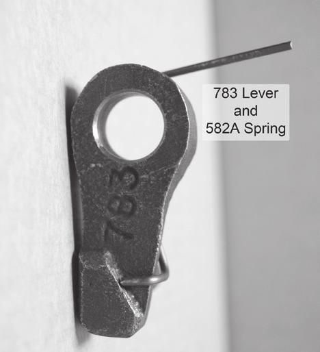
5 Model 880 Coupling SPECIFICATIONS AND LOAD CAPACITIES SAFETY WARNING This product is designed for towing under normal conditions within the stated gross trailer weight. Do not overload or abuse this product. Overloading or abuse may lead to property damage, severe injury, or death. Gross Trailer Weight: Maximum Tongue Weight: Ultimate Latch Capacity: Maximum Eye X-Section: Minimum Eye Opening: Unit Weight: 150,000 lbs. (68,038 kg) 30,000 lbs. (13,607 kg) 30,000 lbs. (13,607 kg) 1 13/16 in. (46 mm) 3 in. (76 mm) 47.5 lbs. (21.6 kg) STANDARD INSTALLATION DRAWING Pushrod length is 5 3/8 in. (137 mm) plus thickness of mounting structure for standard installations as illustrated. REPLACEMENT PART INFORMATION 785Z 384Z Z A A * RK Parts Kit Includes: 266: *271: 274A: 279: 374: 382A: 384Z: 387: Spring Thimble Locknut Shoe Bolt Spring Bolt Locknut 582A: 781: 782: 783: 785Z: 785Z-1: Spring Handle Latch Lever Pin Snap Ring 582A * Not included in parts kit, available individually PARTS Parts Included with 880A: Coupling Bolt Kit Premier Air Chamber Air Chamber Bracket Thimble
6 Optional Accessories: Model 880 Coupling ACCESSORIES - 767H Air Chamber Bracket (3/4 in. / 19 mm) - Thimbles: 271B (4 3/8 in. / 111 mm), 271C (5 1/2 in. / 140 mm) Wear Gage (2 5/8 in.): To determine hook wear limits Latch Gage: To determine latch gap limit. INSTALLATION The 880 Coupling is only to be used and maintained with Premier parts listed in the Replacement Part Information section. Any substitution or use of non-premier parts in a 880 Coupling will VOID ALL PRODUCT WARRANTY. This coupling must be used with an air chamber. Installation Procedure: 1. The 880 Coupling must be installed to comply with the Federal Motor Carrier Safety Regulations. Specifically, Section , Paragraph C: Towing of Full Trailers. Prior to install or operation, consult with local, State and Federal agencies, as there may be additional applicable laws governing installation and use of this product. 2. Make certain that the cross member the 880 Coupling is to be mounted on is of sufficient strength to withstand the load rating of the coupling. 3. Measure the mounting structure thickness and cut the pushrod on the air chamber to a length of 5 3/8 plus the mounting structure thickness (i.e. 1/2 thick mounting structure would equate to: 5 3/8 + 1/2 = 5 7/8 pushrod). 4. Using the Standard Installation Drawing, measure and layout the cross member and then drill the holes for the mounting bolts and pushrod. 5. Mount the 880 Coupling, 282 Air Chamber, 767 Air Chamber Bracket and 271 Thimble as shown in the Standard Installation Drawing using only Premier s 511 Bolt Kit and provided torque value. WARNING: Never use an air chamber on a Premier coupling without a 271 Series Thimble. 6. Once mounted, check the latch components for proper operation and clearances (see the Inspection/Operation/Maintenance section for opening and closing the latch). If the operation of the latch components is sticky, lubricate all rotation points (see the Inspection/Operation/Maintenance section for the lubrication instructions). Work the latch assembly several times to distribute the lubricant evenly and remove any excess with a rag. Do not apply lubricant to the pintle/hook or saddle area of the 880 Coupling. 7. Plumb the air line to the 282 Air Chamber from the vehicle s emergency side air supply. NEVER use the service side air supply. 8. WARNING! Keep hands clear of the 880 Coupling during this test. Activate the emergency side air supply by releasing the emergency brake and visually verify that the 279 Shoe fully rotates toward the pintle. 9. If the 279 Shoe does not move, verify that the air chamber has been connected to the emergency side air supply and that the pushrod length is correct. 10. When the emergency side air supply is removed, the shoe should completely retract. Please note: The 279 Shoe acts as a shock absorbing device to help smooth the ride between vehicles. It is not considered part of the latching mechanism. 11. An IMPORTANT WARNINGS! sticker was enclosed. This must be attached to the coupling or cross member and be visible for the end user to read.
7 Inspection and Maintenance: 1. Visually inspect the coupling body and latch components for cracks, impact damage and/ or deformation before each and every use. Do NOT use if any of these conditions exist. 2. Check the gap between the 782 Latch and the top of the pintle/hook before each and every use. Lift up on the latch to remove any free play and measure the gap. A gap of 3/8 or more means the coupling must be taken out of service and repaired or replaced. 3. If the wear area on the pintle/hook has worn 20% or more from its original cross-section, the coupling is considered out-of-service and must NOT be used. 4. Lubrication of the latch components must be performed at 90-day intervals or sooner depending on the operating environment. Model 880 Coupling INSPECTION / OPERATION / MAINTENANCE Lubricate the latch components with a spraytype lubricant to evenly coat all rotation points. Also lubricate the 384Z Bolt and 785Z Pin at their grease zerks using a mechanical grease gun. Rotate each latch component several times to evenly distribute the lubricant. 5. Remove any excess lubricant with a rag. Do not apply lubricant to the pintle/hook or saddle area of the coupling. 6. Never weld on any Premier part in order to repair damaged or worn areas. Field and/or shop welds are inadequate and may further weaken the coupling. 7. WARNING: Other inspection and maintenance procedures are also required prior to the operation of combination vehicles. Consult and follow all Federal Motor Carrier Safety Regulations as well as local, state and federal guidelines. Operation: OPENING Coupling Latch: 1. While facing the mounted 880 Coupling, lift the 783 Lever, sticking out the left side of the coupling body, upward to the top of the slot and hold it there. 2. Grasp the 781 Handle, projecting out the bottom of the 880 Coupling, and pull outward, away from the back of the vehicle until it runs out of travel. The 782 Latch will open by rotating upward. 3. Release the 783 Lever and 781 Handle. 4. The 880 Coupling is now open and ready to be coupled or uncoupled with a drawbar eye. CLOSING Coupling Latch: 5. With an open palm, push downward on the top of the 782 Latch until it rotates all the way down and is stopped by contacting the top of the pintle on the 880 Coupling body. 6. Visually verify that the latch components have reset to their locked closed position. The 783 Lever should be at the bottom most position of the slot in the side of the coupling body. The 781 Handle must also be back in the closed position nearest the coupling s mounting base as shown in the Standard Installation Drawing. 7. Verify that the 782 Latch is securely closed by grasping the latch and attempting to lift it upward. THE LATCH SHOULD NOT OPEN! If the latch does not stay closed, do not use it until it has been repaired or replaced. 8. This product is designed to be operated within its free rotation limits. It is the responsibility of the vehicle designer/end user to ensure that these limits are not exceeded (do not bind-up/ jackknife). 9. WARNING: Prior to towing, make certain that adequately rated safety chains have been properly connected. IMPORTANT GUIDELINES that apply to all Premier Air Adjusted Couplings - Do not weld on any coupling assembly - Do not apply lubricants to the coupling hook - Air service chamber must be Premier Type-281 or Premier Type-28 with PSI air supply - Clean & inspect coupling for damage & excessive wear prior to each and every use - Lubricate all coupling components at a minimum of 90 day intervals - Do not bind-up (Jackknife) any application as stresses can cause damage to products or components, resulting in failure and detachment of the trailer while in use
8 ATTENTION! End Users must read and follow this information. DISTRIBUTORS & OEM S: Please ensure that your customers are made aware of the following information on this page. (1) VERIFY THAT BOTH COUPLING S AND DRAWBAR EYE S RATED CAPACITIES MEET YOUR APPLICATION(S) REQUIREMENTS. (2) DO NOT OVERLOAD COUPLING OR DRAWBAR EYE. (3) INSPECT COUPLING, LATCH AND DRAWBAR EYE FOR CRACKS, BENDING DAMAGE OR EXCESSIVE WEAR. DO NOT USE IF ANY OF THESE CONDITIONS EXIST! (4) CHECK FOR GAP BETWEEN CLOSED LATCH AND TOP OF HORN OR COUPLING BALL. DO NOT USE IF GAP IS 3/8 IN. OR MORE. (5) MAKE SURE COUPLING IS LATCHED AND THAT LATCH WILL NOT OPEN. (6) PRIOR TO USE, ALWAYS CONNECT SAFETY CHAINS OF ADEQUATE STRENGTH FOR LOAD(S) BEING TOWED. (7) DO NOT BIND-UP (JACKKNIFE) ANY APPLICATION AS STRESSES CAN CAUSE DAMAGE TO THE COUPLING, DRAWBAR EYE, OTHER COMPONENTS OR ANY COMBINATION OF THEM. JACKKNIFING MAY RESULT IN FAILURE OF PRODUCTS OR COMPONENTS, RESULTING IN DETACHMENT OF THE TRAILER WHILE IN USE. (8) DO NOT APPLY LUBRICANTS TO THE COUPLING HOOK OR DRAWBAR EYE LOOP, AS THEY CAN COVER UP POSSIBLE DAMAGE AND ACCELERATE WEAR. (9) ALWAYS ABIDE BY ALL APPLICABLE STATE AND FEDERAL REGULATIONS GOVERNING SAFE AND PROPER TRANSPORTATION. (10) NEVER STRIKE ANY OF THESE COMPONENTS WITH A HAMMER OR ANY OTHER DEVICE. (11) ALWAYS VERIFY PROPER OPERATION OF LATCHING SYSTEM AND COUPLING COMPONENTS PRIOR TO DRIVE OFF. (12) NEVER USE A COUPLING THAT YOU DO NOT FULLY UNDERSTAND HOW TO PROPERLY OPERATE AND VERIFY SECURE LATCHING OF. (13) NEVER REPLACE ANY PART IN ANY OF PREMIER S ASSEMBLIES WITH NON-PREMIER COMPONENTS. DOING SO WILL VOID ALL WARRANTY AND POTENTIALLY COMPROMISE THE UNIT S INTEGRITY, WHICH COULD RESULT IN PROPERTY DAMAGE, SERIOUS INJURY, OR DEATH.

9 THE FIRST NAME IN QUALITY COUPL NGS 880RK SERVICE GUIDELINES 880 Coupling BEFORE GETTING STARTED: This procedure should only be performed by a qualified mechanic. Measure the wear on the coupling s pintle hook. If the wear is at or exceeds 20% of the cross section, the coupling is considered Out of Service. Do Not continue. Tools required: snap ring pliers; grease gun; 1 1/4 & 1 1/16 sockets; long flat-bladed screw driver. CAUTION: When removing and replacing snap rings the appropriate snap ring plier tools are necessary. Do not attempt removal or replacement without the correct snap ring plier tools. In addition, use caution when removing and replacing snap rings Do not over expand them as damage could result. Also, when assembling a snap ring into position - Make certain that the snap ring is fully seated into the groove. Safety glasses are required for all of the following procedures. Prior to disassembly, familiarize yourself with the location of all the various parts in the coupling. This will assist in the assembly process. See attached Image Reference Section(s) with photos and/or drawings to identify various product parts. 3) Looking at the front of the closed 782 Latch, grasp it at the front and pull it toward you, out of the coupling body. There will be tension from the attached spring as you do this. As you pull the 782 Latch out, you should see the 382A Spring attached on the right side. Turn the 782 Latch clockwise, toward the spring, so that it pops off of the mounting peg, or it can be removed with needle nose pliers. 4) Locate the 785Z Pin that resides in the middle body hole. Remove the 785Z-1 Snap Ring from the left side of the 785Z Pin and slide the Pin out of the right side of the body. 5) Locate the bottom body hole and remove the 274A Locknut from the left side of the 374 Bolt and slide the bolt out of the right side of the body. You will need this 374 Bolt later, for reassembly purposes. 6) Remove the remaining parts from the body: 266 Spring; 582A Spring; 279 Shoe; 783 Lever; and 781 Handle. 7) Discard or remove all old parts, except for the 374 Bolt. 8) With all parts removed from the coupling body, clean and inspect the body for wear and/or damage. If wear exists or damage is noted, do not attempt to repair. DO NOT ATTEMPT WELD REPAIR OF ANY DAMAGED AND/OR WORN PART. DISASSEMBLY IS COMPLETE DISASSEMBLY 1) The 880 Coupling body should be positioned with the flat side down (on its mounting base), with the latch in the closed position. See Image #2 on Image Reference Section; the 782 Latch is located at the top of the coupling and the 781 Handle should be sticking out the bottom of the coupling body, with the handle lever pointed to the left. 2) Locate the 384Z Bolt, which resides within the 782 Latch, in the top body hole. Remove the 387 Locknut from the left side of the 384Z Bolt and slide the 384Z Bolt out of the right side of the body. IMPORTANT NOTES TO CLEAN, INSPECT & LUBRICATE: Use only genuine PREMIER replacement parts on any repairs. Use of other parts, which can have different specifications or tolerances, may fail to alert you to non-obvious damage to the hitch which can lead to hitch failure. All body holes, part holes and pins need to be thoroughly cleaned and lubricated with a heavy grease before the parts are reassembled. If a
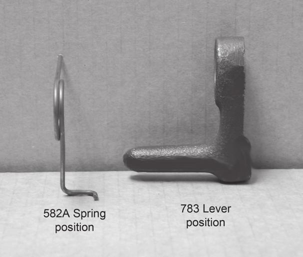
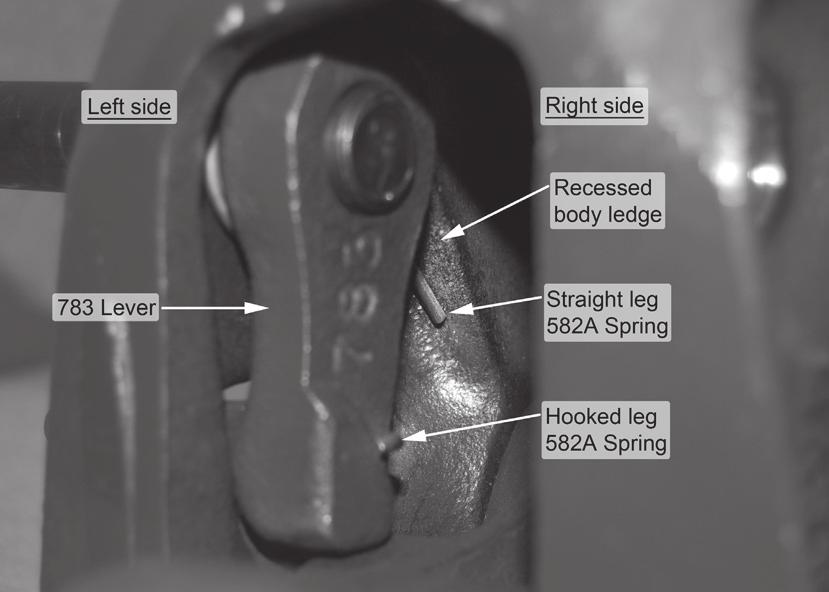
10 bushing resides in a part, lubricate the hole prior to installing the bushing. (DO NOT LUBRICATE PINTLE HOOK WEAR SURFACE). Clean, inspect and lubricate latch components every 90 days or sooner if required by the operating environment. Clean and inspect the coupling for damage and excessive wear prior to each and every use. Do not over-tighten fasteners as this may cause damage. ASSEMBLY 1) From the top, look inside the coupling body and locate two protrusions pointing inward toward each other, but not touching. 2) Grasp the 781 Handle at the handle end so that the lever pointing left, and the spring mounting peg is on the right. In this position, push the 781 Handle up thru the coupling from the bottom, so that it rests on top side of the two protrusions. 3) Locate the spring mounting peg on the top right side of the 781 Handle and place one end of the 382A Spring onto it. Make sure it is fully seated in the groove on the peg. Grasp the 782 Latch with one hand and position it so that the spring mounting peg is on the right side. Place the other end of the 382A Spring onto the 782 Latch mounting peg. Again, make sure it is fully seated in the groove. Keeping tension on the spring, rotate the 782 Latch so that it rests in the open position (see Image #3). 4) The 382A Spring should be connecting the 782 Latch and 781 Handle with tension. 5) While keeping tension in the 382A Spring, grasp the 782 Latch in one hand and the 781 Handle in the other. Start pulling the 781 Handle out of the bottom of the coupling and downward toward the mounting base, so that the top of the handle clears the two protrusions and then slide it back up behind them and up into the body. 6) With this relocation of the 781 Handle, the 782 Latch should be positioned back on top of the coupling body to rest in the open position (see Image #4). 7) From the right side of the coupling, look into the top body hole and align the 782 Latch hole. Place the 384Z Bolt into this hole from the right side and push it through the 782 Latch hole and out the left side of the coupling body. Make certain that one of the flats of the 384Z Bolt head is flush with the flat on the body sidewall. 8) Thread 387 Locknut by hand onto the threaded end of the 384Z Bolt. Do Not tighten. 9) From the right side of the coupling, look into the middle body hole and align the 781 Handle hole. Place the 785Z Pin into this hole from the right side and push it through the 781 Handle hole and out the left side of the coupling body. Make certain that the flat of the 785Z Pin head is flush with the flat on the body sidewall. 10) Use snap ring pliers to place the 785Z-1 Snap Ring into the groove on the left end of the 785Z Pin. Verify that the snap ring is fully seated into the groove. 11) Place your open palm on the back, top side of the 782 Latch. Caution: Keep all body parts clear of the underside of 782 Latch and the top of the pintle hook. With your open palm, rotate the 782 Latch toward you, in the direction of the pintle hook, until it locks closed. 12) Find the old/used 374 Bolt and have it handy. 13) Take the 582A Spring in your left hand. Hold it with the straight leg pointing directly away from you and the long portion of the hooked leg pointing down and hooking out toward the right. In your right hand hold the 783 Lever with the bolt hole on top and the handle of the lever pointing to the left (see Image #5). 14) Take the 582A Spring behind the 783 Lever and then align the right side hole in the spring with the left side hole in the 783 Lever. The hooked leg of the spring should wrap around the bottom back side of the lever (see Image #6). 15) While holding these in position, insert them into the bottom of the coupling body and align the holes on the left bottom bolt hole. The handle of the 783 Lever should protrude out of the lever opening. 16) Keeping the hooked spring leg in position around the lever, push the old/used 374 Bolt into the left side of the body bolt hole and through the 582A Spring and 783 Lever, with approximately 3/4 of the threaded end sticking out the right side of the 783 Lever hole. 17) Look into the bottom opening of the body and, from the right side, insert a long flat-bladed screwdriver into the right side of the bottom body bolt hole until it reaches across to the straight leg of the 582A Spring on the left. Use the screwdriver to rotate the straight leg of the spring down, clockwise, and into the recessed ledge on of the interior body sidewall (see Image #7). Test to make sure that the spring is set, by pushing forward on the 783 Lever. There should be an increase in spring force as you push on it. 18) While making sure that the 582A Spring and 783 Lever stay flush to the left inside body wall, push the 783 Lever forward and lift the 781 Handle upward, in order to open the 782 Latch.
11 19) Push the 783 Lever all the way against the left interior sidewall and slightly pull the 374 Bolt out from the left, until the threaded end is just flush within the right side hole of the 783 Lever. 20) Grasp the 279 Shoe with the bolt hole on the bottom and the nipple pointing toward you. Insert the 279 Shoe down into the body from the top of the coupling, until it rests inside. 21) Again use caution as you place your open palm on the back, top side of the 782 Latch and rotate it toward you, in the direction of the pintle hook, until it locks closed. 22) Make sure the backside of the 279 Shoe bolt hole sits all the way down against the 781 Handle (see Image #8). 23) Palm side up, place one or two fingers into the bottom opening of the coupling body and feel the upper inside body cavity up under the pintle hook. You should feel a deep indented area. This is where one end of the 266 Spring is going to reside. 24) From the bottom opening, place the 266 Spring into the body and put one end of it over the nipple on the 279 Shoe. Now slightly compress the spring while sliding the other end up into the recessed body cavity. 25) Align the 279 Shoe hole with the bottom body bolt hole, from the right side of the body. Place the new 374 Bolt into this hole from the right side and push it into the 279 Shoe. As you continue to push it thru to the left, it should push out the old 374 Bolt from the left side. 26) Thread the 274A Locknut onto the threaded end of the 374 Bolt and tighten until snug. 27) Go back up to the 387 Locknut and tighten it until snug. 28) Coupling is now assembled and should be opened and closed several times, testing for smooth and correct operation. DO NOT use the coupling if it does not operate properly. 29) If operation is smooth, use a grease gun to lubricate the 384Z Bolt and 785Z Pin through the zerk fitting, with 2-3 pumps of grease. NOTE: Use only Premier s 511 Bolt Kit and provided torque value when mounting the assembled coupling to its mounting structure. WARNING: Do NOT bind-up (jackknife) any application, as stresses can cause damage to the hitch, drawbar eye, other components or any combination of them. Jackknifing may result in failure of products or components, resulting in detachment of the trailer while in use. IMPORTANT GUIDELINES that apply to all Premier Air Adjusted Couplings - Do not weld on any coupling assembly - Do not apply lubricants to the coupling hook - Air service chamber must be Premier Type-281 or Premier Type-282 with PSI air supply - Clean & inspect coupling for damage & excessive wear prior to each and every use - Lubricate all coupling components at a minimum of 90 day intervals - Do not bind-up (Jackknife) any application as stresses can cause damage to products or components, resulting in failure and detachment of the trailer while in use

12 IMAGE REFERENCE SECTION IMAGE #1 785Z 384Z Z A A A * : *271: 274A: 279: 374: 382A: 384Z: 387: 582A: 880RK Parts Kit Includes: Spring Thimble Locknut Shoe Bolt Spring Bolt Locknut Spring *Not included in parts kit, available individually. 781: 782: 783: 785Z: 785Z-1: Handle Latch Lever Pin Snap Ring IMAGE #2 Top body hole 384Z Bolt Middle body hole 785Z Pin Bottom body hole 374 Bolt Direction of view for assembly Top of coupling Bottom of coupling Mounting base lying flat on surface


13 IMAGE REFERENCE SECTION IMAGE #3 IMAGE #4 IMAGE #5 IMAGE #6

14 IMAGE #7 IMAGE #8
15 ATTENTION! End Users must read and follow this information. DISTRIBUTORS & OEM S: Please ensure that your customers are made aware of the following information on this page. (1) VERIFY THAT BOTH COUPLING S AND DRAWBAR EYE S RATED CAPACITIES MEET YOUR APPLICATION(S) REQUIREMENTS. (2) DO NOT OVERLOAD COUPLING OR DRAWBAR EYE. (3) INSPECT COUPLING, LATCH AND DRAWBAR EYE FOR CRACKS, BENDING DAMAGE OR EXCESSIVE WEAR. DO NOT USE IF ANY OF THESE CONDITIONS EXIST! (4) CHECK FOR GAP BETWEEN CLOSED LATCH AND TOP OF HORN OR COUPLING BALL. DO NOT USE IF GAP IS 3/8 IN. OR MORE. (5) MAKE SURE COUPLING IS LATCHED AND THAT LATCH WILL NOT OPEN. (6) PRIOR TO USE, ALWAYS CONNECT SAFETY CHAINS OF ADEQUATE STRENGTH FOR LOAD(S) BEING TOWED. (7) DO NOT BIND-UP (JACKKNIFE) ANY APPLICATION AS STRESSES CAN CAUSE DAMAGE TO THE COUPLING, DRAWBAR EYE, OTHER COMPONENTS OR ANY COMBINATION OF THEM. JACKKNIFING MAY RESULT IN FAILURE OF PRODUCTS OR COMPONENTS, RESULTING IN DETACHMENT OF THE TRAILER WHILE IN USE. (8) DO NOT APPLY LUBRICANTS TO THE COUPLING HOOK OR DRAWBAR EYE LOOP, AS THEY CAN COVER UP POSSIBLE DAMAGE AND ACCELERATE WEAR. (9) ALWAYS ABIDE BY ALL APPLICABLE STATE AND FEDERAL REGULATIONS GOVERNING SAFE AND PROPER TRANSPORTATION. (10) NEVER STRIKE ANY OF THESE COMPONENTS WITH A HAMMER OR ANY OTHER DEVICE. (11) ALWAYS VERIFY PROPER OPERATION OF LATCHING SYSTEM AND COUPLING COMPONENTS PRIOR TO DRIVE OFF. (12) NEVER USE A COUPLING THAT YOU DO NOT FULLY UNDERSTAND HOW TO PROPERLY OPERATE AND VERIFY SECURE LATCHING OF. (13) NEVER REPLACE ANY PART IN ANY OF PREMIER S ASSEMBLIES WITH NON-PREMIER COMPONENTS. DOING SO WILL VOID ALL WARRANTY AND POTENTIALLY COMPROMISE THE UNIT S INTEGRITY, WHICH COULD RESULT IN PROPERTY DAMAGE, SERIOUS INJURY, OR DEATH.
Model 470 / 470H Coupling
 MANUFACTURING CO. THE FIRST NAME IN QUALITY COUPLINGS Installation, Inspection, Operation & Maintenance Guide 470 470H Model 470 / 470H Coupling IMPORTANT Read these instructions completely before installing,
Model 580 / 580J Coupling
 MANUFACTURING CO. THE FIRST NAME IN QUALITY COUPLINGS Installation, Inspection, Operation & Maintenance Guide Model 580 / 580J Coupling IMPORTANT Read these instructions completely before installing, using
Model 240K / 240KL Coupling
 MANUFACTURING CO. THE FIRST NAME IN QUALITY COUPLINGS Installation, Inspection, Operation & Maintenance Guide Model 240K / 240KL Coupling IMPORTANT Read these instructions completely before installing,
Installation, Inspection, Operation & Maintenance Guide
 MANUFACTURING CO. THE FIRST NAME IN QUALITY COUPLINGS Installation, Inspection, Operation & Maintenance Guide 238DB, 245DB & 245DB-3 Bolt-On Drawbar Eyes IMPORTANT Read these instructions completely before
Saf-Tite Coupling
 MANUFACTURING CO. THE FIRST NAME IN QUALITY COUPLINGS Installation, Inspection, Operation & Maintenance Guide Raising the Bar SAF TITE Strength & Value Saf-Tite 100-3 Coupling IMPORTANT Read these instructions
Saf-Tite / 100-4H Coupling
 MANUFACTURING CO. THE FIRST NAME IN QUALITY COUPLINGS Installation, Inspection, Operation & Maintenance Guide Raising the Bar SAF TITE Strength & Value Saf-Tite 100-4 / 100-4H Coupling IMPORTANT Read these
Model 240K / 240KL Coupling
 MANUFACTURING CO. THE FIRST NAME IN QUALITY COUPLINGS Installation, Inspection, Operation & Maintenance Guide Model 240K / 240KL Coupling IMPORTANT Read these instructions completely before installing,
Model 580 / 580J Coupling
 MANUFACTURING CO. THE FIRST NAME IN QUALITY COUPLINGS Installation, Inspection, Operation & Maintenance Guide Model 580 / 580J Coupling IMPORTANT Read these instructions completely before installing, using
Model 2200ELL Coupling
 MANUFACTURING CO. THE FIRST NAME IN QUALITY COUPLINGS Installation, Inspection, Operation & Maintenance Guide Model 2200ELL Coupling IMPORTANT Read these instructions completely before installing, using
Model 320 / 320A Hinge Assembly
 MANUFACTURING CO. THE FIRST NAME IN QUALITY COUPLINGS Installation, Inspection, Operation & Maintenance Guide Model 320 / 320A Hinge Assembly IMPORTANT Read these instructions completely before installing,
270PK SERVICE GUIDELINES
 270 Coupling THE FIRST NAME IN QUALITY COUPLINGS 270PK SERVICE GUIDELINES BEFORE GETTING STARTED: This procedure should only be performed by a qualified mechanic. Measure the wear on the coupling s pintle
Model 690L / 690R / 690T Coupling
 MANUFACTURING CO. THE FIRST NAME IN QUALITY COUPLINGS Installation, Inspection, Operation & Maintenance Guide Model 690L / 690R / 690T Coupling IMPORTANT Read these instructions completely before installing,
MANUFACTURING CO. THE FIRST NAME IN QUALITY COUPLINGS. Installation, Inspection, Operation & Maintenance Guide. Model 150 Coupling IMPORTANT
 MANUFACTURING CO. THE FIRST NAME IN QUALITY COUPLINGS Installation, Inspection, Operation & Maintenance Guide Model 150 Coupling IMPORTANT Read these instructions completely before installing, using or
Model 407SE Swivel Drawbar Eye
 MANUFACTURING CO. THE FIRST NAME IN QUALITY COUPLINGS Installation, Inspection, Operation & Maintenance Guide Model 407SE Swivel Drawbar Eye IMPORTANT Read these instructions completely before installing,
Model 6 Weld-On Drawbar Eye
 MANUFACTURING CO. THE FIRST NAME IN QUALITY COUPLINGS Installation, Inspection, Operation & Maintenance Guide Model 6 Weld-On Drawbar Eye IMPORTANT Read these instructions completely before installing,
Model 123 Weld-On Adjustable Drawbar Eye
 MANUFACTURING CO. THE FIRST NAME IN QUALITY COUPLINGS Installation, Inspection, Operation & Maintenance Guide Model 123 Weld-On Adjustable Drawbar Eye IMPORTANT Read these instructions completely before
Model 330 / 330A Hinge Assembly
 MANUFACTURING CO. THE FIRST NAME IN QUALITY COUPLINGS Installation, Inspection, Operation & Maintenance Guide Model 330 / 330A Hinge Assembly IMPORTANT Read these instructions completely before installing,
580RK SERVICE GUIDELINES For coupling models: 580 & 580J
 580 Coupling THE FIRST NAME IN QUALITY COUPLINGS 580RK SERVICE GUIDELINES For coupling models: 580 & 580J BEFORE GETTING STARTED: This procedure should only be performed by a qualified mechanic. Measure
MANUFACTURING CO. THE FIRST NAME IN QUALITY COUPLINGS
 MNUFCTURING CO. THE FIRST NME IN QULITY COUPLINGS 2016 TTENTION! End Users must read and follow this information. DISTRIBUTORS & OEM S: Please ensure that your customers are made aware of the following
MANUFACTURING CO. (503) (800) THE FIRST NAME IN QUALITY COUPLINGS
 (800) THE FIRST NAME IN QUALITY COUPLINGS") MNUFCTURING CO. THE FIRST NME IN QULITY COUPLINGS 2016 www.premier-mfg.com (503) 234-9202 (800) 255-5387 TTENTION! End Users must read and follow this information. DISTRIBUTORS & OEM S: Please ensure that
MNUFCTURING CO. THE FIRST NME IN QULITY COUPLINGS 2016 www.premier-mfg.com (503) 234-9202 (800) 255-5387 TTENTION! End Users must read and follow this information. DISTRIBUTORS & OEM S: Please ensure that
BX4330 Acclaim Tow Bar Operator Manual & Installation Instructions
 Operator Manual & Installation Instructions (5,000 lb) 2 Inch Coupler General Information DO NOT INSTALL, OPERATE OR USE THIS EQUIPMENT UNTIL THE FOLLOWING OPERATING AND SAFETY INSTRUCTIONS HAVE BEEN READ
BX7322 Adventurer Tow Bar Operator Manual & Installation Instructions. (5,000 lb) 2 Inch Coupler
 2 Inch Coupler") Operator Manual & Installation Instructions (5,000 lb) 2 Inch Coupler General Information DO NOT INSTALL, OPERATE OR USE THIS EQUIPMENT UNTIL THE FOLLOWING OPERATING AND SAFETY INSTRUCTIONS HAVE BEEN READ
Operator Manual & Installation Instructions (5,000 lb) 2 Inch Coupler General Information DO NOT INSTALL, OPERATE OR USE THIS EQUIPMENT UNTIL THE FOLLOWING OPERATING AND SAFETY INSTRUCTIONS HAVE BEEN READ
<THESE INSTRUCTIONS MUST BE GIVEN TO THE END USER> B&W
 B&W Trailer Hitches 6 Hawaii Rd / PO Box 86 Humboldt, KS 66748 P:60.473664 F:60.869.903 Turnoverball Gooseneck Hitch Installation Instructions MODEL 08
B&W Trailer Hitches 1216 Hawaii Road / PO Box 186 Humboldt, KS P: F:
 B&W Trailer Hitches 1216 Hawaii Road / PO Box 186 Humboldt, KS 66748 P:620.473.3664 F:620.473.3766 NOTE: We recommend reading instructions before beginning the installation. GM OEM Mount System Slider
MAINTENANCE WEIGHT RATINGS WARNINGS. warning: never exceed your vehicle manufacturer's recommended towing capacity
 Installation instructions warning: never exceed your vehicle manufacturer's recommended towing capacity Round Bar WEIGHT DISTRIBUTION MAINTENANCE Keep the socket-mounted ends of the spring bars and the
BX4330 Acclaim Tow Bar Operator Manual & Installation Instructions
 Operator Manual & Installation Instructions Serial Number (5,000 lb) 2 Inch Coupler 292-2205 Rev J Page 1 of 7 4/23/13 DO NOT INSTALL, OPERATE OR USE THIS EQUIPMENT UNTIL THE FOLLOWING OPERATING AND SAFETY
Model 3770 WARNING. Failure to comply with the safety information in these instructions could result in serious injury or death.
 B&W Trailer Hitches 1216 Hawaii Road / PO Box 186 Humboldt, KS 66748 P:620.473.3664 See Limited Lifetime Warranty at F:620.869.9031 bwtrailerhitches.com/warranty NOTE: We recommend reading instructions
<THESE INSTRUCTIONS MUST BE GIVEN TO THE END USER> B&W
 B&W Trailer Hitches 1216 Hawaii Rd / PO Box 186 Humboldt, KS 66748 P:620.473.3664 F:620.869.9031 Turnoverball Gooseneck Hitch Installation Instructions
<THESE INSTRUCTIONS MUST BE GIVEN TO THE END USER> B&W Trailer Hitches 1216 Hawaii Road / PO Box 186 Humboldt, KS P: F:
 B&W Trailer Hitches 26 Hawaii Road / PO Box 86 Humboldt, KS 66748 P:620.473.3664 F:620.869.903 Ford OEM Mount System Installation Instructions 20,000
MAINTENANCE WEIGHT RATINGS WARNINGS. warning: never exceed your vehicle manufacturer's recommended towing capacity
 Installation instructions warning: never exceed your vehicle manufacturer's recommended towing capacity Round Bar WEIGHT DISTRIBUTION kit MAINTENANCE Keep the socket-mounted ends of the spring bars and
Bumper Bumper Removal and Installation. 1. Bumper 2. Front Mounting Brackets 3. End Mounting Brackets
 Bumper.0 Bumper Removal and Installation 0/9/00. Bumper. Front Mounting Brackets. End Mounting Brackets f88088 Fig., Bumper, -Inch Steel Logger, Severe Service, Set-Back Axle Coronado Workshop Manual,
B&W Trailer Hitches 1216 Hawaii Road / PO Box 186 Humboldt, KS P: F:
 B&W Trailer Hitches 1216 Hawaii Road / PO Box 186 Humboldt, KS 66748 P:620.473.3664 F:620.869.9031 NOTE: We recommend reading instructions before beginning the installation. Ford OEM Mount System Slider
Owner s Manual. Rigid Mount Weld-on Drawbars. XL-DB20016UM-en-US Rev
 Owner s Manual Rigid Mount Weld-on Drawbars Installation, Operation and Maintenance Procedures For on/off-road applications Weight: DB-1400 (approx.) 14 lbs. (6.35 kg) DB-1422 (approx.) 11 lbs. (4.98 kg)
<THESE INSTRUCTIONS MUST BE GIVEN TO THE END USER> B&W Trailer Hitches 1216 Hawaii Road / PO Box 186 Humboldt, KS P: F:
 B&W Trailer Hitches 26 Hawaii Road / PO Box 86 Humboldt, KS 6678 P:620.73.366 F:620.869.903 Ford OEM Mount System Installation Instructions 20,000 LBS.
SwayPro. NOTE: A minimum tongue weight of 200 lbs. is required THANK YOU
 SwayPro Owner s Manual & Installation Instructions Serial Number Standard Hitch Head w/ Clamp-On Rotating Latches BXW0350 350 lbs. maximum tongue weight capacity BXW0550 550 lbs. maximum tongue weight
INSTALLATION INSTRUCTIONS
 INSTALLATION INSTRUCTIONS WARNING: NEVER EXCEED YOUR VEHICLE MANUFACTURER'S RECOMMENDED TOWING CAPACITY TRUTRACK TRUNNION BAR WEIGHT DISTRIBUTION SYSTEM MAINTENANCE Keep the socket-mounted ends of the
<THESE INSTRUCTIONS MUST BE GIVEN TO THE END USER> B&W Trailer Hitches 1216 Hawaii Road / PO Box 186 Humboldt, KS P: F:
 B&W Trailer Hitches 26 Hawaii Road / PO Box 86 Humboldt, KS 6678 P:620.73.366 F:620.869.903 RAM OEM Mount System Installation Instructions 25,000 LBS.
INSTALLATION INSTRUCTIONS
 INSTALLATION INSTRUCTIONS WARNING: NEVER EXCEED YOUR VEHICLE MANUFACTURER'S RECOMMENDED TOWING CAPACITY PIN-STYLE TRUNNION BAR WEIGHT DISTRIBUTION KIT MAINTENANCE Keep the socket-mounted ends of the spring
Owner s Manual. DB Bolt-On Drawbar. XL-DB20014UM-en-US Rev
 Owner s Manual DB-1249-49 Bolt-On Drawbar Installation, Operation and Maintenance Procedures For on/off-road applications Weight: (approx.) 24 lbs. (10.8 kg) For Load Ratings, Refer to Section 3 XL-DB20014UM-en-US
Installation instructions
 Installation instructions warning: never exceed your vehicle manufacturer's recommended towing capacity BOLT-TOGETHER WEIGHT DISTRIBUTION MAINTENANCE Keep the socket-mounted ends of the spring bars and
SPRING MAX. TONGUE MAX. GROSS TRAILER BAR WEIGHT(LB) WEIGHT (LB)
 WEIGHT (LB)") INSTALLATION / OPERATION INSTRUCTIONS WEIGHT DISTRIBUTING HITCH SYSTEMS 7901, 7902, 7903, 7979 (DUAL SWAY CONTROL ATTACHMENT) 7901=600LB WDH KIT, 7902=800LB WDH KIT, 7903=1200LB WDH KIT, 7979=HEAD KIT
INSTALLATION / OPERATION INSTRUCTIONS WEIGHT DISTRIBUTING HITCH SYSTEMS 7901, 7902, 7903, 7979 (DUAL SWAY CONTROL ATTACHMENT) 7901=600LB WDH KIT, 7902=800LB WDH KIT, 7903=1200LB WDH KIT, 7979=HEAD KIT
HR-520 HOIST. Installation & Operation Manual. To Be Filled In By Installer. Pump Installation And Operation Manual#: In Service Date: Dealer:
 Website: www.tbei.com E-mail: sales@tbei.com Phone: 1-800-869-9162 Rugby 1-800-255-4345 DuraClass 1-800-533-0494 Crysteel HR-520 HOIST Installation & Operation Manual To Be Filled In By Installer Hoist
ALPHA Tow Bar (6,500 lb) 2 Inch Receiver
 2 Inch Receiver") Operator Manual & Serial Number ALPHA Tow Bar (6,500 lb) 2 Inch Receiver 405-0154 Rev C Page 1 of 7 7/29/13 DO NOT INSTALL, OPERATE OR USE THIS EQUIPMENT UNTIL THE FOLLOWING OPERATING AND SAFETY INSTRUCTIONS
Operator Manual & Serial Number ALPHA Tow Bar (6,500 lb) 2 Inch Receiver 405-0154 Rev C Page 1 of 7 7/29/13 DO NOT INSTALL, OPERATE OR USE THIS EQUIPMENT UNTIL THE FOLLOWING OPERATING AND SAFETY INSTRUCTIONS
<THESE INSTRUCTIONS MUST BE GIVEN TO THE END USER> B&W
 B&W Trailer Hitches 26 Hawaii Road / PO Box 86 Humboldt, KS 6678 P:620.73.366 F:620.869.903 GM Puck Mount System Installation Instructions 20,000 LBS.
<THESE INSTRUCTIONS MUST BE GIVEN TO THE END USER> B&W
 B&W Trailer Hitches 1216 Hawaii Rd / PO Box 186 Humboldt, KS 66748 Turnoverball Gooseneck Hitch Installation Instructions MODEL 1314 2013 2014 RAM 3500
HR-540/HR-550 HOIST Installation & Operation Manual
 Website: www.tbei.com E-mail: sales@tbei.com Phone: 1-800-869-9162 Rugby 1-800-255-4345 DuraClass 1-800-533-0494 Crysteel HR-540/HR-550 HOIST Installation & Operation Manual To Be Filled In By Installer
Owner s Manual. PH-T-60-AOS-L-8 Swivel Mount Pintle Hook. XL-PH20032UM-en-US Rev A
 Owner s Manual PH-T-60-AOS-L-8 Swivel Mount Pintle Hook Installation, Operation and Maintenance Procedures For On and Off-Road Applications Maximum GTW: 18,000 lb. (8,165 kg) Maximum Vertical Load:,600
Rating when used as a weight distributing hitch with spring bars:
 May 2004 APPLICATION: INSTALLATION INSTRUCTIONS MODEL NO. 70201 Bolt Together Weight Distributing Hitch System Without Shank Rating when used as a weight distributing hitch with spring bars: Part Number
INSTALLATION INSTRUCTIONS READ THOROUGHLY BEFORE BEGINNING
 Catalog No. 6320 INSTALLATION INSTRUCTIONS READ THOROUGHLY BEFORE BEGINNING 6320 RAIL KIT - 1988 through 2000 Chevrolet/GMC Pickup w/6 ft. bed, 1999 Chevrolet C/K LS and GMC Sierra Classic w/6 ft. bed
WARNING. BX Nissan Sentra S/SV/SR/SL Installation Instructions
 Attachment Tab Height: 14 Attachment Tab Width: 22 Please read BOTH these and the General Information sheet prior to installing or operating this equipment. 1. Blue Ox towing products and accessories are
Rating when used as a weight distributing hitch with spring bars:
 January 2007 INSTALLATION INSTRUCTIONS 70210 70220 70230 Bolt Together Weight Distributing Hitch System Rating when used as a weight distributing hitch with spring bars: Part Number Max. Tongue Wt. Max
FIFTH WHEELS TROUBLESHOOTING AND REBUILD PROCEDURES. XA-71 Series Fifth Wheel Top Plates. XA-71-DA 2 SAE Kingpin (Rebuild Kit RK-65014)
") GO THE DISTANCE. FIFTH WHEELS TROUBLESHOOTING AND REBUILD PROCEDURES XA-71 Series Fifth Wheel Top Plates XA-71-DA 2 SAE Kingpin (Rebuild Kit RK-65014) XA-71-DA-03705 2 SAE Kingpin for FW2570-7103 SERIES
GO THE DISTANCE. FIFTH WHEELS TROUBLESHOOTING AND REBUILD PROCEDURES XA-71 Series Fifth Wheel Top Plates XA-71-DA 2 SAE Kingpin (Rebuild Kit RK-65014) XA-71-DA-03705 2 SAE Kingpin for FW2570-7103 SERIES
Please read BOTH these Installation Instructions and the General Information sheet prior to installing or operating this equipment.
 2015-18 Chevy Suburban/Tahoe 2015-18 GMC Yukon/Yukon XL (Includes Denali) Please read BOTH these and the General Information sheet prior to installing or operating this equipment. 1. Blue Ox towing products
ASSEMBLY INSTRUCTIONS Signature Series Gooseneck
 ASSEMBLY INSTRUCTIONS Signature Series Gooseneck DEALER/INSTALLER: (1) Provide this Manual to end user. (2) Physically demonstrate procedures in this Manual to end user. (3) Have end user demonstrate that
<THESE INSTRUCTIONS MUST BE GIVEN TO THE END USER> B&W
 B&W Trailer Hitches 1216 Hawaii Rd / PO Box 186 Humboldt, KS 66748 P:620.473664 F:620.869.9031 Turnoverball Gooseneck Hitch Installation Instructions
WARNING. BX Fiat 500L Trekking/Easy/Pop/Lounge Installation Instructions
 2014-16 Fiat 500L Trekking/Easy/Pop/Lounge Attachment Tab Height: 15 Attachment Tab Width: 23 Please read BOTH these and the General Information sheet prior to installing or operating this equipment. 1.
Installation Instructions for the EVO3 Height-Adjustable Ultimate Short Shifter. for F80 M3 and F82 M4
 Installation Instructions for the EVO3 Height-Adjustable Ultimate Short Shifter for 2013+ F80 M3 and F82 M4 part number USSF80 Thank you for purchasing the Ultimate Shift Kit. Please read these directions
Please read BOTH these Installation Instructions and the General Information sheet prior to installing or operating this equipment.
 2011-13 Mini Cooper Hardtop (Includes S) 2012-15 Mini Cooper Coupe (Includes S) 2009-15 Mini Cooper Convertible (Includes S) 2012-15 Mini Cooper Roadster (Includes S) 2008-14 Mini Cooper Clubman (Includes
MAINTENANCE WEIGHT RATINGS WARNINGS. warning: never exceed your vehicle manufacturer's recommended towing capacity
 Installation instructions warning: never exceed your vehicle manufacturer's recommended towing capacity Pin-style trunnion Bar WEIGHT DISTRIBUTION MAINTENANCE Keep the socket-mounted ends of the spring
CHEVROLET TAHOE/DENALI/AVALANCHE/YUKON/ SILVERADO/SIERRA 2007+
 CHEVROLET TAHOE/DENALI/AVALANCHE/YUKON/ SILVERADO/SIERRA 2007+ INSTALLATION INTRODUCTION 1. REMOVING THE FENDER AND DOORS FROM THE A-PILLAR AND DISCONNECTING THE WIRE HARNESS @ THE DOOR JAM 2. REMOVING
Owner s Instructions and Safety Manual. Switcharoo series. Performance Bicycle Trailers
 Owner s Instructions and Safety Manual Switcharoo series TM Performance Bicycle Trailers Contents 1. Trailer Components 2. Tow Bar and Hitch Components 3. Assembling Your Trailer 4. Attaching the Wheels
SUPPORT USA JOBS. Made in USA INSTALLATION MANUAL. 24,000 lbs GTWR, 6,000 lbs tongue
 SUPPORT USA JOBS Made in USA INSTALLATION MANUAL # 3100 Straight Adapter # 3139 8" Offset Adapter 24,000 lbs GTWR, 6,000 lbs tongue ! IMPORTANT SAFETY INFORMATION! Regularly check all hardware, bolts and
Maintenance Information
 80234313 Edition 2 May 2014 Air Grinder, Die Grinder, Sander and Belt Sander Series G1 (Angle) Maintenance Information Save These Instructions Product Safety Information WARNING Failure to observe the
Wheel Horse. 44 Snowthrower. for 5xi Lawn and Garden Tractors. Model No & Up. Operator s Manual
 FORM NO. 8 Rev A Wheel Horse Snowthrower for 5xi Lawn and Garden Tractors Model No. 7966 890050 & Up Operator s Manual IMPORTANT: Read this manual, and your tractor manual, carefully. They contain information
<THESE INSTRUCTIONS MUST BE GIVEN TO THE END USER> B&W Trailer Hitches 1216 Hawaii Rd / PO Box 186 Humboldt, KS P: F:
 B&W Trailer Hitches 6 Hawaii Rd / PO Box 86 Humboldt, KS 6678 P:60.7366 F:60.73766 Turnoverball Gooseneck Hitch Installation Instructions MODEL 38 0 06
Hydraulic Hand Pallet Trucks
 Operating Instructions & Parts Manual 12U124 Please read and save these instructions. Read carefully before attempting to assemble, install, operate, or maintain the product described. Protect yourself
Maintenance Information
 16572679 Edition 2 May 2014 Air Drill QP Series Maintenance Information Save These Instructions Product Safety Information WARNING Failure to observe the following warnings, and to avoid these potentially
WARNING. BX Dodge Dart SE/SXT/GT/Limited Installation Instructions
 BX2410 Attachment Tab Height: 14 Attachment Tab Width: 22 Please read BOTH these and the General Information sheet prior to installing or operating this equipment. 1. Blue Ox towing products and accessories
BX4325 Aladdin Tow Bar Operator Manual & Installation Instructions. ALADDIN Tow Bar (7,500 lb) 2 Inch Receiver
 2 Inch Receiver") Operator Manual & Installation Instructions ALADDIN Tow Bar (7,500 lb) 2 Inch Receiver General Information 1. Ensure that your product(s) are registered online. It is crucial to register your product(s)
Operator Manual & Installation Instructions ALADDIN Tow Bar (7,500 lb) 2 Inch Receiver General Information 1. Ensure that your product(s) are registered online. It is crucial to register your product(s)
<THESE INSTRUCTIONS MUST BE GIVEN TO THE END USER> B&W
 B&W Trailer Hitches 6 Hawaii Rd / PO Box 86 Humboldt, KS 6678 P:60.7366 F:60.86.03 Turnoverball Gooseneck Hitch Installation Instructions MODEL 38 0 08
Installation Instructions
 Equipment Required: Wrenches: 9/16, 3/4, 1-1/8 Drill Bits: 11/32 Torque Wrench capable of reading 260 ft-lbs. Installation Instructions IN DEALERS: Please give these instructions to your customer. Do Not
COMPANION OEM HITCH YOUR TOWING ADVENTURE BEGINS
 COMPANION OEM HITCH YOUR TOWING ADVENTURE BEGINS DON'T WORRY YOUR HITCH WAS MADE RIGHT HERE. You ve got a lot riding on your hitch and the only thing keeping your truck and your trailer connected are
B&W Trailer Hitches 1216 Hawaii Road / PO Box 186 Humboldt, KS P: F: " Split Lock Washers 8
 B&W Trailer Hitches 1216 Hawaii Road / PO Box 186 Humboldt, KS 66748 P:620.473.3664 F:620.869.9031 NOTE: We recommend reading instructions before beginning the installation. Companion Slider Hitch Installation
TOPAZ Service Guide. Full Service
 TOPAZ Service Guide Full Service SERVICE OVERVIEW This manual will guide you step by step performing an air service to your Topaz. Please follow each instruction carefully to achieve the best and safest
HYDRAULICS. TX420 & & lower. Hydraulic Tandem Pump Removal. 4. Remove the LH side panel (Fig. 0388).
.") TX420 & 425 240000299 & lower 4. Remove the LH side panel (Fig. 0388). Hydraulic Tandem Pump Removal Note: Cleanliness is a key factor in a successful repair of any hydraulic system. Thoroughly clean all
TX420 & 425 240000299 & lower 4. Remove the LH side panel (Fig. 0388). Hydraulic Tandem Pump Removal Note: Cleanliness is a key factor in a successful repair of any hydraulic system. Thoroughly clean all
5 th Wheel Air Ride Connect and Uncoupling Procedure
 5 th Wheel Air Ride Connect and Uncoupling Procedure East Coast Partners Grp 1041 Old Blush Road., Suite 200 Celebration, FL 34747 Phone 321-939-2132 / Fax 866-201-3391 sales@airsafehitches.com www.airsafehitches.com
Owner s Manual Hybrid/Crossover
 Owner s Manual Hybrid/Crossover This manual contains safety information and instructions for your trailer. You must read this manual before loading or towing your trailer. You must follow all safety precautions
<THESE INSTRUCTIONS MUST BE GIVEN TO THE END USER> B&W Trailer Hitches 1216 Hawaii Rd / PO Box 186 Humboldt, KS P: F:
 B&W Trailer Hitches 26 Hawaii Rd / PO Box 86 Humboldt, KS 66748 P:620.473664 F:620.869.903 Turnoverball Gooseneck Hitch Installation Instructions Mounting
Auto-Locking Pintle Hook
 Auto-Locking Pintle Hook 7-Ton Capacity Owner s Manual WARNING: Read carefully and understand all ASSEMBLY AND OPERATION INSTRUCTIONS before operating. Failure to follow the safety rules and other basic
BX Chevy Equinox Installation Instructions
 Attachment Tab Height: 16 Attachment Tab Width: 23 Please read BOTH these and the General Information sheet prior to installing or operating this equipment. 1. Blue Ox towing products and accessories are
Installation Instructions for the EVO3 Height-Adjustable Ultimate Short Shifter
 Installation Instructions for the EVO3 Height-Adjustable Ultimate Short Shifter for 1992-2005 325, 323, 318 and 1986-1994 525, 528, 535, 540 5-speed models only. (part number USSE3 and USSE5) Thank you
<THESE INSTRUCTIONS MUST BE GIVEN TO THE END USER> B&W Trailer Hitches 1216 Hawaii Rd / PO Box 186 Humboldt, KS P: F:
 B&W Trailer Hitches 26 Hawaii Rd / PO Box 86 Humboldt, KS 66748 P:620.473664 F:620.473766 Turnoverball Gooseneck Hitch Installation Instructions Mounting
Maintenance Information
 80234313 Edition 1 June 2006 Air Grinder, Die Grinder, Sander and Belt Sander Series G1 (Angle) Maintenance Information Save These Instructions WARNING Always wear eye protection when operating or performing
BX7322 Adventurer Tow Bar Operator Manual & Installation Instructions
 Please visit www.blueox.com for the latest version of these installation instructions. BX7322 Operator Manual & Installation Instructions Serial Number (5,000 lb) 2 Inch Coupler 292-1263 Rev J Page 1 of
Owner s Manual Enclosed Cargo
 Owner s Manual Enclosed Cargo 1 This manual contains safety information and instructions for your trailer. You must read this manual before loading or towing your trailer. You must follow all safety precautions
INSTALLATION INSTRUCTIONS
 INSTALLATION INSTRUCTIONS 6525 REAR AXLE FLIP & HANGER KIT 5 OR 6 INCH LOWERING 14&UP CHEVROLET SILVERADO / GMC SIERRA 1500 Thank you for being selective enough to choose our high quality BELLTECH PRODUCT.
WARNING. BX Honda Civic (Includes Turbo) Installation Instructions
 Installation Instructions") Attachment Tab Height: 12.5 Attachment Tab Width: 23 Please read BOTH these and the General Information sheet prior to installing or operating this equipment. 1. Blue Ox towing products and accessories
Attachment Tab Height: 12.5 Attachment Tab Width: 23 Please read BOTH these and the General Information sheet prior to installing or operating this equipment. 1. Blue Ox towing products and accessories
BX7322 Adventurer Tow Bar Operator Manual & Installation Instructions
 Please visit www.blueox.com for the latest version of these installation instructions. BX7322 Operator Manual & Installation Instructions Serial Number (5,000 lb) 2 Inch Coupler 292-1263 Rev J Page 1 of
Model 3400 ATTENTION: WARNING
 B&W Trailer Hitches 1216 Hawaii Road / PO Box 186 Humboldt, KS 66748 P:620.473.3664 F:620.473.3766 NOTE: We recommend reading instructions before beginning the installation. Companion Slider Hitch Installation
CDL Series Pre-Trip Inspection AT-TC3TS T1-JA01. Pre-Trip Inspection Checklist
 Pre-Trip Inspection Checklist This checklist covers different parts of the vehicle you would check before a trip. Note that some specifications described in the following content may not be the same as
'99-03 CHEVROLET/GMC IFS 4WD 6" SUSPENSION SYSTEM P/N INSTALLATION INSTRUCTIONS
 1/16/04 '99-03 CHEVROLET/GMC IFS 4WD 6" SUSPENSION SYSTEM P/N. 10-41099 INSTALLATION INSTRUCTIONS NOTE: Each Lift Kit and options to Lift Kits are packaged separately. Therefore, installation procedures
MODEL 2604 WARNING <THESE INSTRUCTIONS MUST BE GIVEN TO THE END USER> Custom 5th Wheel Hitch Mounting Rail Installation Instructions
 B&W Trailer Hitches 1216 Hawaii Rd / PO Box 186 Humboldt, KS 66748 P:620.473.3664 F:620.869.9031 Custom 5th Wheel Hitch Mounting Rail Installation Instructions
Swing Back Trailer Jack
 Swing Back Trailer Jack Model: 91474 ASSEMBLY AND OPERATING INSTRUCTIONS Diagrams within this manual may not be drawn proportionally. Due to continuing improvements, actual product may differ slightly
Maintenance Information
 04581245 Edition 2 May 2014 Air Grinder, Die Grinder and Sander Series G2 (Angle) Maintenance Information Save These Instructions Product Safety Information WARNING Failure to observe the following warnings,
LIGHT DUTY ROLL UP DOOR
 1-800-225-6729 LIGHT DUTY ROLL UP DOOR CAUTION Use proper lifting equipment and correct lifting procedures to avoid damage or injury. MODEL 150C installation guide A rolling door is a large heavy object
Please visit for the latest version of these installation instructions.
 Please visit www.blueox.com for the latest version of these installation instructions. BX2338 2012-17 Hyundai Accent GLS/SE (Includes Foglights) Attachment Tab Height: 14 Serial Number Attachment Tab Width:
Installation Manual TWM Performance Short Shifter Subaru Forester up to 2005
 - 1 - Installation Manual TWM Performance Short Shifter Subaru Forester up to 2005 Please Note: It is preferable to park on a flat surface, as you will have to engage and disengage the hand brake and shift
Please visit for the latest version of these installation instructions.
 Please visit www.blueox.com for the latest version of these installation instructions. Attachment Tab Height: 13-1/2 Serial Number Attachment Tab Width: 24 Please read BOTH these and the General Instructions
INSTALLATION INSTRUCTIONS
 INSTALLATION INSTRUCTIONS --1075 North Ave. Sanger, CA 93657-3539 local: 559-875-0222 fax: 559-876-2259 toll free: 800-445-3767-- 2505 Lowering Spindle Assembly Installation Instructions ½ TON SILVERADO
Discount-Equipment.com
 REQUIRED TOOLS LS Series Remix Shaft Installation Instructions /8", /6", /2" Allen Wrenches Snap Ring Pliers (Light Duty) /" Combination Wrench Loctite #22 Blue /" Socket w/ /8" Ratchet Electric Drill