OPTIMIZER TM OPERATOR MANUAL. Author: Labrie. Release Date: 1/31/07. Part #: 90320
|
|
|
- Edgar Melton
- 6 years ago
- Views:
Transcription

1
2

3 OPTIMIZER TM OPERATOR MANUAL Author: Labrie Release Date: 1/31/07 Part #: 90320
4
5 Table of Contents Introduction Introducing the Optimizer TM... 1 Product Overview... 1 Contacting Labrie Environmental Group... 3 Plant information... 3 Labrie Customer Support Center... 3 Chapter 1 Safety Safety Conventions... 5 Responsibilities of the Employer... 5 Responsibilities of the Employee... 6 Lockout/Tagout... 6 Protection Against Fire... 7 Location of Safety Labels... 8 Chapter 2 Controls on the Optimizer TM Parking Brake... 9 Pump Switch... 9 Joystick Packer Controls Red Button Green Button Yellow Button Hopper Roof Gate Switch Part #: iii
6 Tailgate Switch Chapter 3 Operating the Optimizer TM Approaching the Vehicle Starting the Vehicle Inspecting the Body Collecting Refuse with the Optimizer TM Packing Refuse in the Body Unloading the Optimizer TM Cleaning the Hopper of the Optimizer TM iv Part #: 90320
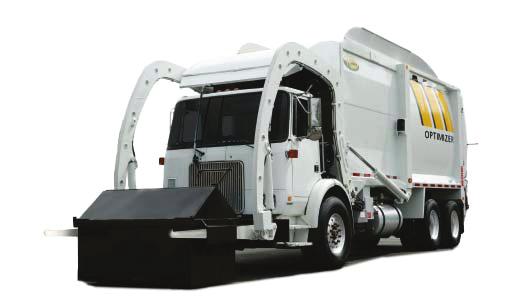
7 INTRODUCTION INTRODUCING THE OPTIMIZER TM The Optimizer TM is a front load refuse collection vehicle. It picks up dumpsters from two to ten cubic yard volume and dumps their content into its body. Once the body is full, all its content is unloaded on a waste management landfil. This vehicle is conceived to be operated by only one person at a time and uses a series of hydraulic, pneumatic, mechanic, and electrical systems to perform its work routine. Figure 1. Optimizer TM Product Overview The Optimizer TM is made up of a 36 to 40 c.y. body, depending on the model, mounted on a chassis and a set of automated arms and forks to perform the collection of industrial and commercial waste. The body s main components are the hopper, the packer and the tailgate. The hopper being the area of the body receiving the waste, the packer being the element that compresses the waste in the body and the tailgate being the component allowing waste to either stay in the body or to come out when unloading. Part #:
8 HOPPER PACKER TAILGATE Figure 2. Body s main components On the other hand, there is the chassis with its cab being the controls room. In the cab you find the controls console housing most of the switches, light indicators and levers that control most of the functions of the Optimizer TM. Also in the cab, you find one or two joysticks to control the funtions of the arms and forks (See "Joystick" on page 10). Then, there are the automated arms and forks which help you pick up solid refuse containers and dump their contents in the hopper of the Optimizer TM. Figure 3. Arms and forks 2 Part #: 90320
9 CONTACTING LABRIE ENVIRONMENTAL GROUP Plant information Address 175 du Pont St-Nicolas (Quebec) CANADA G7A 2T3 Phone: (418) Fax: Sales Dept.: (418) Service & Warranty: (418) Parts: (418) Labrie Customer Support Center Address 3596 Stearns Drive Oshkosh, WI Hot Line Technical Support, Service & Warranty: 24-Hour Service Parts: 8am through 7pm ET Web Site: IMPORTANT FOR TECHNICAL SUPPORT AND PARTS ORDERING, THE SERIAL NUMBER OF YOUR VEHICLE IS REQUIRED, THEREFORE, LABRIE ENVIRONMENTAL GROUP RECOMMENDS TO KEEP RECORD OF THE INFORMATION FOUND ON THE VIN PLATE WHICH IS LOCATED IN THE CAB. Part #:
10
11 SAFETY Being a heavy duty vehicle, the use of the Optimizer TM entitles a number of safety issues. Such issues, along with all necessary safety instructions and conventions, are presented in this section of the Operator Manual. SAFETY CONVENTIONS DANGER INDICATES AN IMMINENTLY HAZARDOUS SITUATION WHICH, IF NOT AVOIDED, WILL RESULT IN DEATH OR SERIOUS INJURY. WARNING INDICATES A POTENTIALLY HAZARDOUS SITUATION WHICH, IF NOT AVOIDED, COULD RESULT ON DEATH OR SERIOUS INJURY. CAUTION INDICATES A POTENTIALLY HAZARDOUS SITUATION WHICH, IF NOT AVOIDED, MAY RESULT IN MINOR OR MODERATE INJURY. Responsibilities of the Employer It is the responsibility of the employer: To ensure the operation of the Optimizer TM is in accordance with all safety requirements and codes, including all applicable regulations, the Occupational Safety and Health Act (OSHA) and the American National Standards Institute (ANSI). To ensure the employees are qualified for the operation of the equipment and take all safety measures before working with this equipment. To properly maintain all mobile equipment to meet all provincial/state and federal safety standards. To supply adequate instructions and training for the safe use of the vehicle before assigning the employee to such equipment. Part #:
12 To keep the vehicle maintained and properly adjusted to meet the manufacturer s standards and recommendations. For help or more information, contact the manufacturer or any authorized representative. To keep record of any breakdowns or malfunctions of the vehicle as well as any inspection and maintenance. To ensure the repair of any failures or malfunctions that may affect the safe use of the vehicle, always before it is used again. To meet the appropriate lighting requirements for night shift work (if permitted). To regularly accompany the operator of the vehicle and take measures to ensure the smooth and safe operation of the vehicle. To make sure that the backup alarm works properly while the vehicle is in reverse. To take the necessary measures that follow a damage or malfunction report from any employee. To establish and ensure the application of a Lockout/Tagout Procedure at the time of any inspection, repair or maintenance to the vehicle, whether it takes place on the road or in the garage. Responsibilities of the Employee It is the responsibility of the employee: To enforce all safety measures to meet the requirements established by the employer. To operate the Optimizer TM only after having received instructions and training. To immediately report to the employer or supervisor about any damage or malfunction of the vehicle. To make sure that there is nobody near the vehicle before activating any of the controls and be prepared to stop everything upon the existence of possible danger. LOCKOUT/TAGOUT The Lockout/Tagout procedure must be applied to render the vehicle out of service and thus ensure its safety and that of those who will be around it. To lock out and tag out the Optimizer TM : 1. Apply the parking brake. 2. Turn off the hydraulic system and the engine. 6 Part #: 90320
13 Figure 4. Parking brake 3. Remove the key from the ignition switch. 4. Place the key in a safe and controlled area. 5. Cover the ignition switch with tape. Note:If the Optimizer TM is equipped with a master switch on the battery set, you must turn it off. 6. Put an OFF SERVICE tag on the driver s wheel. 7. Put an OFF SERVICE sign on the front windshield. 8. Use a safety prop to block any system that could move by gravity. (Open tailgate, etc.) 9. Drain all air tanks. 10. Move all control levers to release any residual pressure in the system. PROTECTION AGAINST FIRE It is mandatory to have an ABC-type fire extinguisher easily accessible from both, outside and inside the cab. Figure 5. Fire extinguisher Part #:


14 LOCATION OF SAFETY LABELS In the event safety labels need to be ordered and installed on the vehicle, the following guide will help you with their corresponding part numbers and location Figure 6. Labels on the right-hand side Figure 7. Labels on the left-hand side 8 Part #: 90320
15 CONTROLS ON THE OPTIMIZER TM The Optimizer TM has a series of controls that allow the user to more easily operate the different functions installed on the vehicle. Such controls are mainly located in the cab and the following is a description of each one of them. PARKING BRAKE The parking brake located in the cab, usually on the dashboard center, must be used every time the Optimizer TM is stopped on idle position other than the regular traffic stops. Figure 8. Parking brake PUMP SWITCH The pump switch turns on and off the hydraulic system of the Optimizer TM. It is located on the console and is accompanied by a red light to indicate when the hydraulic system is on. Such red light denotes a condition where the user must be aware that the hydraulic functions on the Optimizer TM are available. DANGER ALWAYS BE AWARE OF THE SURROUNDINGS AND SURE OF THE TASKS TO ACCOMPLISH WHILE THE RED LIGHT INDICATING PUMP ENGAGED IS ON. ANY ACCIDENTAL PUTTING INTO MOTION OF THE HYDRAULIC COMPONENTS WILL CAUSE SERIOUS INJURY OR DEATH IF YOU DO NOT COMPLY WITH THIS SAFETY NOTION. Part #:

16 Pump switch Figure 9. Pump switch on the console JOYSTICK The joystick is used to control the arms and forks of the Optimizer TM. It is located to the right-hand side of the driver. It is also possible to have two joysticks inside the cab. One is used to control the forks and the other one is used to control the arms. Figure 10. Joysticks 10 Part #: 90320

17 Figure 11. Single Joystick PACKER CONTROLS Three buttons located on the console control the different packer functions. Red Button The red button is an emergency feature. When pressed, it instantly cuts off all hydraulic functions. Therefore, none of the systems such as the packer, tailgate or arms, just to mentioned a few, moves at all avoiding thus injuries and damages. Red emergency button Figure 12. Red emergency button on the console Part #:

18 Green Button The green button has two functions depending on the circumstances the packer is used. To start the packer for a full extend/retract cycle to pack refuse on the body. For such use, you press it once and the cycle is automatically completed. To start the packer for a complete extension stroke to eject the refuse from the body. For such use, you press and hold it until you feel the packer has reached the end of its stroke. Green button Figure 13. Green button on the console 12 Part #: 90320
19 Yellow Button The yellow button has two functions. To start the packer for a complete retraction stroke after refuse has been ejected from the body. For such use, you press and hold it until you feel the packer has reached the end of its stroke. To retract the packer during the packing cycle when it doesn t reach the end of its normal stroke. Yellow button Figure 14. Yellow button on the console Hopper Roof Gate Switch The Hopper roof gate switch controls the opening and closing of the hopper roof gate. It is located on the console and accompanied by a green light to indicate when the hopper roof gate is fully open. Such a green light indicates a condition that has to be met to be able to use the arms. In other words, if the roof gate is not fully open, the arms and forks will be inoperable. Part #:
20 Roof gate switch Roof gate open light Figure 15. Roof gate switch on the console Tailgate Switch The tailgate switch controls the opening and closing of the tailgate. It is located on the console and accompanied by a red light to indicate when the tailgate is fully open and a red light to indicate when the taigate is unlocked. The red light indicating the tailgate is fully open denotes a condition that has to be met when unloading the body of the Optimizer TM. That is, the packer will not extend to eject the refuse unless the tailgate has been fully open. Tailgate switch Tailgate fully open light Tailgate unlocked light Figure 16. Tailgate switch on the console The red light indicating the tailgate is NOT locked denotes a condition that has NOT been met and therefore, an alarm is sent out. Other hydraulic functions on the
21 Optimizer TM, such as the paker, will be disabled while the tailgate has not been fully closed and locked. WARNING DO NOT DRIVE THE VEHICLE IF THE TAILGATE IS NOT FULLY CLOSED. Part #:
22 16 Part #: 90320
23 OPERATING THE OPTIMIZER TM The different methods, procedures and necessary actions to operate the Optimizer TM are presented in this section of the Operator Manual. WARNING ALWAYS READ AND UNDERSTAND THE USER S GUIDE BEFORE OPERATING THE EQUIPEMENT. APPROACHING THE VEHICLE As you approach the vehicle, look for any foreign object around or under it. Check the surroundings for people, other vehicles, and overhead obstructions. Ensure that the Optimizer TM is in an safe area where you will have all the clearance required to perform the complete start-of-the-day inspection. STARTING THE VEHICLE Before starting the vehicle, the operator MUST perform a visual inspection of the truck. Visual inspection 1. Look around the vehicle for accessible lights, safety labels, camera lenses, etc. and clean them with a dry cloth. 2. Look for any structural damage. 3. Check for mechanical problems, rollers, hinges, door locks, wear items, etc. Report any defective system to maintenance personnel. 4. Make sure that the tailgate safety pins are in place. Part #:
24 Locking mechanism Safety pin position to open tailgate Safety pin position to lock tailgate Figure 17. Tailgate safety pins 5. Check the frame area, fuel tank, hydraulic tank, air tanks (air tanks must be drained every day), cleaning trap and wheels for leaks, cracks or other types of problems. 6. Once the visual inspection is over, you must start the engine to check if the systems are working properly. To start the Optimizer TM : 1. Before starting the truck, check the following items: Transmission shifter is on neutral. Parking brake is on. See Parking Brake on page 9. Hydraulic system is off. See Pump Switch on page Open the chassis manufacturer manual and start the vehicle as stated therein. 3. Turn ON the Pump switch on the control console to engage the hydraulic system (the air pressure has to be at a minimum of 70 PSI). See Pump Switch on page Turn on all light switches, (position, strobe, driving and work lights). 5. Report any defective system to the maintenance personnel. 18 Part #: 90320
25 INSPECTING THE BODY After the vehicle visual inspection, there comes the inspection of the Optimizer TM s body. To inspect the Optimizer TM s body: 1. Check the side hopper door for proper latching. Note: If the side door (or hopper door) is open, the hydraulic pump won t work. The side door MUST be closed in order to start the hydraulic pump. DANGER NEVER ATTEMPT TO REACH INSIDE THE HOPPER AREA WHEN THE PACKER IS IN MOTION. SEVERE INJURY OR DEATH WILL OCCUR. 2. Go in the truck, open the roof and press on the green button (console) to activate the packer one full cycle. See Green Button on page 12. Figure 18. Hopper door 3. Activate the arms and forks to see if they are working properly. 4. Go around the back, check lights, camera, safety labels, etc. Report any defective systems to maintenance personnel. Note:Some of the items mentioned herein may not be part of your Optimizer TM. They are optional and may or may not be included in the original Purchase Order. Part #:
26 COLLECTING REFUSE WITH THE OPTIMIZER TM You should carefully follow the following instructions to ensure a safe and efficient collection. All the safety notions mentioned herein are of outmost importance and you should obey them at all times. WARNING INSURE TOTAL CLEARANCE OF PEDESTRIANS AND BYSTANDERS AT ALL TIMES. To start collecting refuse with the Optimizer TM : 1. Turn on the hydraulic system and open the hopper roof gate. Hopper roof gate closed Hopper roof gate open Figure 19. Hopper roof gate 2. Align the arms and forks with the container side pockets. 3. Cautiously drive forward to insert the forks in the container side pockets. Step 3. Step 2. Figure 20. Arms and forks aligned with container 20 Part #: 90320
27 4. Put the transmission to neutral and apply the parking brake. See Parking Brake on page 9. DANGER BEFORE MOVING THE ARMS, LOOK AGAIN ALL AROUND AND ON TOP OF THE VEHICLE TO MAKE SURE THERE IS NO OBSTRUCTIONS WHATSOEVER. SPECIAL ATTENTION TO ELECTRICAL WIRES AND TREE BRANCHES. 5. Retract the packer completely to avoid debris falling on or behind it. If the packer is not completely retracted, it is impossible to raise the arms. Note: If the unit is equipped with the ARM PARTLY RAISED proximity switch, the operator will be able to raise the arms while the packer is retracting. But if the packer is not completely retracted when the ARM PARTLY RAISED proximity switch detects the arms, the arms will stop automatically. 6. Move the arms joystick towards you to raise the arms. See Joystick on page 10. Tip: While raising the arms and consequently the container, you should adjust the forks to make sure the container does not prematurely spill or dump refuse over the cab. At this height, you must adjust the forks Figure 21. Container being lifted and forks adjusted 7. With the arms already on the top, pivot the forks to let all refuse come out of the container and into the hopper. CAUTION DO NOT PIVOT THE FORKS ALL THE WAY TO UNLOAD THE CONTAINER, IT MAY CAUSE THE CONTAINER TO SLIDE OFF THE FORKS AND FALL IN THE HOPPER. Part #:

28 DANGER LOOK ALL AROUND AGAIN TO INSURE TOTAL CLEARANCE. MAKE SURE NO ONE IS NEAR THE VEHICLE. AVOID THIS SITUATION! Figure 22. Dumping container 8. Lower the arms to put the container back on the ground. Note:At this point you can press the green button on the console to start a packer cycle and pack the refuse in the body. It possible to pack when travelling from one point to another. PACKER EXTENDED (PACKING POSITION) PACKER COMPLETELY RETRACTED (HOME POSITION) Figure 23. Packing cycle 9. Release the parking brake, put the transmission on reverse and look around again. 10. Drive on reverse 5 to 10 feet to free the container from the forks. 11. Pivot the forks (fully retracted) and completely raise the arms. 22 Part #: 90320
29 ARMS AND FORKS IN SAFE DRIVING POSITION Figure 24. Safe driving position 12. Before going to the landfill or driving on a long distance, close the hopper roof gate and turn off the hydraulic system. See Hopper Roof Gate Switch on page 13 and Pump Switch on page 9. Packing Refuse in the Body When some containers have already been unloaded in the hopper, the packer of the Optimizer TM will help you clear the hooper area by packing the refuse in the body. Note: Labrie Environmental Group recommends to perform this task while you move from one collection point to another. To pack refuse in the body: 1. Turn on the hydraulic system. See Pump Switch on page 9. Note: If the side door (or hopper door) is open, the hydraulic pump won t work. The side door MUST be closed in order to start the hydraulic pump. 2. Open the Hopper Roof. 3. Press the green button to start the packer cycle. See Green Button on page 12. Unloading the Optimizer TM Once the body of the Optimizer TM is full, it is time to unload it at the corresponding landfill. To unload the Optimizer TM : 1. Drive it to the landfill. 2. Once you have chosen the area where to dump the refuse, park the vehicle on safe, level ground. 3. Get off the cab and check for overhead clearance or any kind of obstruction. 4. Remove the tailgate safety pins. Part #:
30 5. Back in the cab, push and hold the tailgate switch to OPEN position. Wait until the green light next to the switch turns on to indicate the tailgate is fully open. Also, a TAILGATE UNLOCKED red light and a buzzer turn on as soon as you start opening the tailgate. Green button Tailgate switch PACKER EXTENDED (UNLOADING POSITION) Tailgate open light Figure 25. Control console and packer on Eject position 6. Press the green button to extend the packer all along the body and eject the refuse. See Green Button on page 12. PACKER COMPLETELY RETRACTED (HOME POSITION) Yellow button Figure 26. Packer completely retracted 7. Press the yellow button to retract the packer and bring it back to its home position. See Yellow Button on page Push and hold the tailgate switch to the CLOSE position. Wait for the TAILGATE UNLOCKED red light to turn off indicating the tailgate is fully closed and locked. 24 Part #: 90320

31 CLEANING THE HOPPER OF THE OPTIMIZER TM For an efficient and safe performance of the different functions of the Optimizer TM, it is necessary to daily clean the hopper area. To clean the hopper area of the Optimizer TM : WARNING MAKE SURE THE OPTIMIZER TM IS IN AN AREA WITH TOTAL CLEARANCE TO PERFORM CLEANING AND MAINTENANCE. 1. Turn on the engine and the hydraulic system. 2. Open the hopper roof gate. Hopper roof gate closed Hopper roof gate open 3. Remove the tailgate safety pins. Figure 27. Hopper roof gate 4. Fully open the tailgate. A green light on the console turns on to prompt you about it. 5. Press and hold the green button on the console to move the packer all the way to the end of its stroke. Green button Tailgate switch PACKER EXTENDED (UNLOADING POSITION) Tailgate open light Figure 28. Control console and packer on Eject position Part #:
32 6. Apply the Lockout/Tagout procedure. See Lockout/Tagout on page Open the hopper door on the right side of the body. DANGER NEVER CLOSE THE HOPPER DOOR BEHIND YOU WHILE YOU ARE INSIDE THE HOPPER AREA. 8. Get in the hopper area and remove any residual material. Use a high pressure water jet to complete the cleaning. 9. Get off the vehicle and close the hopper door. Figure 29. Hopper door closed 10. Back in the cab, turn on the engine and the hydraulic system. 11. Press and hold the yellow button on the console to retract the packer to its home position. See Yellow Button on page 13. PACKER COMPLETELY RETRACTED (HOME POSITION) Yellow button 12. Close the hopper roof gate. Figure 30. Packer completely retracted. 13. Close the tailgate, turn off the engine, and put the safety pins back into place. 26 Part #: 90320
33 Part #:
34
35

36
6 OPERATION GENERAL PRECAUTIONS... 19
 ROTOPAC TABLE OF CONTENTS TABLE OF CONTENTS 1 INTRODUCTION... 1 2 USEFUL ADDRESS AND PHONE NUMBERS... 2 3 RECEIVING INSTRUCTIONS... 3 4 ORDERING REPLACEMENT PARTS... 3 5 GENERAL SAFETY INSTRUCTIONS AND
Durapack Python Automated Side Loader (Heil Garbage Truck 2006 Units)
") Durapack Python Automated Side Loader (Heil Garbage Truck 2006 Units) Maintenance and Adjustment Safety Messages During repairs to the tailgate, packing mechanism, or hydraulic drive system, a lockout
Durapack Python Automated Side Loader (Heil Garbage Truck 2006 Units) Maintenance and Adjustment Safety Messages During repairs to the tailgate, packing mechanism, or hydraulic drive system, a lockout
MAINTENANCE MANUAL RELEASE:
 MAINTENANCE MANUAL RELEASE: February 2007 Part Number: 90313 FOREWORD Here is the new Labrie parts and maintenance manual for the OPTIMIZER TM front loading unit. We sincerely hope that you will find
1500 Series Roll Off Hoist. Owner s Manual (5-06)
") 1500 Series Roll Off Hoist Owner s Manual (5-06) Section 1: General Information Introduction Safety Information Warranty Information Table of Contents Section 2: Operation Operating the P.T.O. Operating
1500 Series Roll Off Hoist Owner s Manual (5-06) Section 1: General Information Introduction Safety Information Warranty Information Table of Contents Section 2: Operation Operating the P.T.O. Operating
DuraPack Python AUTOMATED SIDE LOADER. Operator s Manual. 2005, The Heil Co. #MR
 DuraPack Python AUTOMATED SIDE LOADER Operator s Manual 2005, The Heil Co. #MR-74958-105 SECTION 1 - GENERAL Introduction... 1.2 Warranty Claims/Inquiries... 1.2 Service/Parts Assistance... 1.3 Directional
HELPING HAND EXPERT 2000
 HELPING HAND Release date: January 2005 Part #47916 rev. 0 2-2 2-3 HELPING HAND AUTOMATED ARM Table of contents 2.0 HELPING HAND MAINTENANCE... 2-5 2.1 HYDRAULIC SYSTEM MAINTENANCE... 2-5 2.1.1 HYDRAULIC
John Yvars, Sanitation Superintendent Town of Mooresville
 John Yvars, Sanitation Superintendent Town of Mooresville 1 http://www.kmbc.com/news/trash-truckworker-killed-in-accident/14265936 2 Indiana OSHA Cites City in Worker s Death 2013 The City of Indianapolis
Operator Manual. This operator manual has. information for all models. of series M plus some. options and accessories. Some of the illustrations
 M S E R I E Operator Manual S This operator manual has information for all models of series M plus some options and accessories. Some of the illustrations and information may not The most apply to your
Commander 15i Container and Pallet Loader. Property of American Airlines
 Commander 15i Container and Pallet Loader Section 2. Operation BEFORE ATTEMPTING TO OPERATE OR MAINTAIN THE VEHICLE, COMPLETELY READ AND UNDERSTAND THE OPERATION AND MAINTENANCE MANUAL, INCLUDING ALL DANGER,,
Begin Program: Welcome everyone and introduce yourself, speaker(s) and/or interpreter if one is present/necessary. Feel free to include your name/prog
 and/or interpreter if one is present/necessary. Feel free to include your name/prog") Begin Program: Welcome everyone and introduce yourself, speaker(s) and/or interpreter if one is present/necessary. Feel free to include your name/program name on the title slide for purposes of personalization.
Begin Program: Welcome everyone and introduce yourself, speaker(s) and/or interpreter if one is present/necessary. Feel free to include your name/program name on the title slide for purposes of personalization.
Operator Manual. The most important component is you. This operator manual. has information for. all models of series. B plus some options and
 Operator Manual This operator manual has information for all models of series B plus some options and accessories. Some of the illustrations and information may not apply to your truck. The most important
JARVIS. BRE -1 and BRE -2 BUNG RING EXPANDER EQUIPMENT... TABLE OF
 BRE -1 and BRE -2 BUNG RING EXPANDER EQUIPMENT SELECTION... Ordering No. TABLE OF CONTENTS... Page BRE--1... 4021002 BRE--2... 4021008 Air Hose, 16 feet long... 1059002 Balancer... 4042043 Notice to Employer
T6 Owners Manual. Basic Function
 T6 Owners Manual Basic Function The T6 is a frameless aluminum end dump trailer. It is used mainly for hauling sand, gravel and dirt. The material is discharged by extending the hoist which raises the
Table of Contents General Information Safety Message Classifi cation...2 Safety Notes...3 Terminology...4 Coupler Lifting Lug...
 Table of Contents General Information Safety Message Classifi cation...2 Safety Notes...3 Terminology...4 Coupler Lifting Lug...6 Assembly and Installation General Information...7 How it works...7 Component
Wind and Temperature Tip Over Hazard Do not add notice boards or similar
 Lift & Work Platform Safety Information Safety Information: Boom Lifts Safety Information: Scissor Lifts Safety Information: Boom Lifts Power Lines Electrocution Hazard Maintain safe clearance from Electrical
Powered Industrial Truck Safety Program
 Powered Industrial Truck Safety Program 0 TABLE OF CONTENTS Forklift Safety Program 1.0 Overview.. 2 2.0 Purpose....2 3.0 Procedures..2 4.0 Responsibilities. 4 5.0 Training Requirements......5 Appendix
PNEUMATIC SLIDING VALVE
 INSTALLATION, OPERATION, & #: MM-SV001 6-23-09 Rev. A Page 1 of 8 PNEUMATIC SLIDING VALVE PART NUMBERS (Including, but not inclusive) SV704MSTS, SV714MSTS, SV754MSTS, SV764MSTS, SV774MSTS, SV706MSTS, SV716MSTS,
Maintenance and Operating Instructions PG Style Pipe Grapple
 Maintenance and Operating Instructions PG Style Pipe Grapple Read this manual before installing, operating or servicing this product. This manual contains important information. Make this manual available
610 BUSHEL MANURE SPREADER
 610 BUSHEL MANURE SPREADER RODA MANUFACTURING 1008 LOCUST ST. HULL, IA. 51239 Art s-way Manufacturing 712-439-2366 Co., Inc. Hwy 9 West - PO Box 288 WWW.RODAMFG.COM Armstrong, IA. 50514 U.S.A 2 INTRODUCTION
PW Operator Manual PW This operator manual. has information for all. models of series PW plus some options. and accessories.
 Operator Manual PW 3000 S E R I E S This operator manual has information for all models of series PW 3000 plus some options and accessories. Some The most of the illustrations and important component information
Trench Filler for Compact Utility Loaders
 Form No. 3353-608 Rev A Trench Filler for Compact Utility Loaders Model No. 22472 260000001 and Up Operator s Manual Register your product at www.toro.com Original Instructions (EN) Contents Page Introduction................................
3-Stage Under Axle Jack Weight: 69.5 kg (153 lbs.)
") 655 Eisenhower Drive Owatonna, MN 55060-0995 USA Phone: (507) 455-7000 Tech. Serv.: (00) 533-627 Fax: (00) 955-329 Order Entry: (00) 533-627 Fax: (00) 23-665 International Sales: (507) 455-7223 Fax: (507)
655 Eisenhower Drive Owatonna, MN 55060-0995 USA Phone: (507) 455-7000 Tech. Serv.: (00) 533-627 Fax: (00) 955-329 Order Entry: (00) 533-627 Fax: (00) 23-665 International Sales: (507) 455-7223 Fax: (507)
UTS 696 Under Tailgate Spreader Owner s Manual
 July 15, 2004 Lit. No. 94838 UTS 696 Under Tailgate Spreader Owner s Manual Read this manual before installing or operating the spreader. This manual is for UTS 696 Under Tailgate Spreaders with serial
This lift will not operate with the generator engaged.
 WARNING 40' GENIE S40 PERSONNEL BOOM LIFT Any piece of equipment can be dangerous if not operated properly. YOU are responsible for the safe operation of this equipment. The operator must carefully read
Hazards in Sanitation. Presented by: Josh Kemp, CSEA OSH Specialist
 Hazards in Sanitation Presented by: Josh Kemp, CSEA OSH Specialist Agenda Introduction Sanitation Fatalities Regulatory Requirements Other Sanitation Hazards Discussion What do you think are some of the
LKS300/LKS450 OPERATOR S MANUAL
 LKS300/LKS450 OPERATOR S MANUAL SAFETY RULES SHIFTA 300/450 Conveyor DANGER Failure to obey the instructions and safety rules in this manual will result in death or serious injury. Do Not Operate Unless:
Request for Proposal. Rear Load Refuse Truck
 Request for Proposal Rear Load Refuse Truck December 29, 2015 RFP Bidding Specifications 1.0 INTENT It is the intent of this specification to provide for the purchase of two (2) new and unused Rear Load
Work Platforms. Operators Manual Warning Stickers ANSI Standards. ( Model # MWP 4x4 ) ( Model # MWP 4x6 ) ( Model # MWP 4X8 ) ( Model # MWP 4x116 )
 ( Model # MWP 4x6 ) ( Model # MWP 4X8 ) ( Model # MWP 4x116 )") Work Platforms ( Model # MWP 4x4 ) ( Model # MWP 4x6 ) ( Model # MWP 4X8 ) ( Model # MWP 4x116 ) Operators Manual Warning Stickers ANSI Standards Marv Haugen Enterprises 1851 Heartland Ave. 1851 Heartland
Work Platforms ( Model # MWP 4x4 ) ( Model # MWP 4x6 ) ( Model # MWP 4X8 ) ( Model # MWP 4x116 ) Operators Manual Warning Stickers ANSI Standards Marv Haugen Enterprises 1851 Heartland Ave. 1851 Heartland
NORTH CAROLINA SHERIFFS ASSOCIATION
 NORTH CAROLI SHERIFFS ASSOCIATION Name of Dealership Type of Vehicle Zone LABRIE STARLITE FRONT LOADER - 40 CUBIC YARDS (Specification #69) Base Unit Price Appalachia $93,313.00 Dogwood $93,313.00 Cardinal
Tree Forks Sitework Systems Attachment
 Form No. 3323-274 Tree Forks Sitework Systems Attachment Model No. 22438 890001 & Up Operator s Manual English (CE) Contents Page Introduction................................. 2 Safety......................................
Provided by: Operating, Maintenance & Parts Manual
 Provided by: www.hoistsdirect.com TB681.qxd 11/29/2004 3:04 PM Page 1 Operating, Maintenance & Parts Manual TB603 Manually Lever Operated Chain Hoist 1100 POUNDS MAXIMUM CAPACITY (500 kg) Follow all instructions
PLATFORM WHEEL WELL ACCESS STAND
 PLATFORM WHEEL WELL ACCESS STAND Page 1 Standards WARNING Safety First Tested in general accordance with the applicable requirements of DIN EN 131 2 : 2012 BS EN 131 7 : 2013 ANSI ASC A14.7 20 2011 The
New Bremen, Ohio USA 2004 PF14387-WEB Rev. 6/06 Printed in U.S.A.
 New Bremen, Ohio 45869 USA 2004 PF14387-WEB Rev. 6/06 Printed in U.S.A. You Must be Trained It s the law, you must be trained and certified to operate this truck. (OSHA 1910.178, Rev. 1999) You or others
CAUTION. Start & Stop Procedures. Section 1-2. Engine Oil Level
 Section 1-2 Start & Stop Procedures Before operating this machine, the operator must have: received operator training, a familiarity with this manual, and a complete understanding of all the procedures
CAUTION. Start & Stop Procedures. Section 4-2. Engine Oil Level
 Section 4-2 Start & Stop Procedures Before operating this machine, the operator must have: received operator training, a familiarity with this manual, and a complete understanding of all the procedures
Important. Contents. Contact us:
 Operator's Manual First Edition Ninth Printing Important Read, understand and obey these safety rules and operating instructions before operating this machine. Only trained and authorized personnel shall
TEXAS A&M INTERNATIONAL UNIVERSITY
 TEXAS A&M INTERNATIONAL UNIVERSITY ENVIRONMENTAL HEALTH & SAFETY GOLF CART/UTILITY VEHICLE TRAINING GUIDE Date of Preparation: 06/01/2011 Last Update: 08/03/2017 I. PURPOSE The purpose of this training
Risk Management Department. Forklift Safety
 Risk Management Department Forklift 1 Introduction to Forklift Operating a forklift is an important job. So important that the federal government requires that all lift truck operators be trained and authorized
Technical Publications AWP. Operator's Manual. Fourth Edition, First Printing Part No
 Technical Publications AWP Operator's Manual Fourth Edition, First Printing Part No. 424 Operator s Manual Fourth Edition Important Read, understand and obey these safety rules and operating instructions
While handling materials, employees must abide by the following requirements:
 Material Handling and Equipment 12.1 Material Handling by Individuals While handling materials, employees must abide by the following requirements: a) Know the safe way to lift: i. A secure footing, feet
Maintenance and Operation Manual for Landing Gear Access Stand
 Maintenance and Operation Manual for Landing Gear Access Stand DF071592 03 Liftsafe Fall Protection Inc. Landing Gear Access Stand Manual Page 1 Table of Contents Section Page Number 1.0 Standards 3 2.0
Rugby Manufacturing SR-Series Hoist Manual. Preface INSTALLATION & OPERATION MANUAL
 Preface INSTALLATION & OPERATION MANUAL INTRODUCTION IMPORTANT!! Read this manual thoroughly prior to installation and operation. This manual outlines the installation and operation of an SR-series hoist
OPERATOR S MANUAL 7(5 & ( 8&. $5.00 P/N REV.B
 OPERATOR S MANUAL &281 2817( 7(5 %$/$1&( /,)7 7758& 8&. $5.00 P/N 901345 REV.B As a lift truck operator, you are responsible for a machine that is useful, powerful, and can be hazardous if not operated
HORTICULTURE EQUIPMENT & SERVICES
 HORTICULTURE EQUIPMENT & SERVICES OPERATOR S MANUAL PEAT BALE PROCESSOR Model Number: LH00 Serial Number: 30000 & UP Contents Introduction Page Safety Safety 2 Safety Decal Instructions 2 Specifications
6602LP CAPACITY: 2 TON LOW RIDER SERVICE JACK
 CONTENTS: Page 1 Specifications 2 Warning Information 3 Setup Instructions 4 Operating Instructions, Preventative Maintenance, Inspection and Proper Storage 5 Hydraulic Jack Maintenance Guide and Regular
Property of American Airlines
 - GASOLINE MANUAL NUMBER 092602 EFFECTIVITY: 09/26/02 GASOLINE POWERED Scissor Lift Vehicle -1036S thru -1037S REV 00 CORPORATION 9501 SOUTH CENTER ROAD MUNCIE, IN 47302-9443 P.O. BOX 2645 MUNCIE, IN 47307-0645
Important. Contents. Contact us:
 Operator's Manual Third Edition Third Printing Important Read, understand and obey these safety rules and operating instructions before operating this machine. Only trained and authorized personnel shall
FPU SYSTEMS OPERATION MANUAL (INCLUDING REPAIR PARTS & SPECIAL TOOL LIST) BOH CONTAINERIZED MISSION SYSTEMS CCC and EWCC BOH FPU Field Pack-up Units
 BOH CONTAINERIZED MISSION SYSTEMS CCC and EWCC BOH FPU Field Pack-up Units") FPU SYSTEMS OPERATION MANUAL (INCLUDING REPAIR PARTS & SPECIAL TOOL LIST) BOH CONTAINERIZED MISSION SYSTEMS CCC and EWCC BOH FPU Field Pack-up Units CHAPTER 2 OPERATOR INSTRUCTIONS 2016 BOH Environmental
FPU SYSTEMS OPERATION MANUAL (INCLUDING REPAIR PARTS & SPECIAL TOOL LIST) BOH CONTAINERIZED MISSION SYSTEMS CCC and EWCC BOH FPU Field Pack-up Units CHAPTER 2 OPERATOR INSTRUCTIONS 2016 BOH Environmental
BEFCO. Operator s Manual BABY HOP & HOP FERTILIZER SPREADERS ACCESSORIES SIDE ROW DISCHARGE. AA4-120 (fits models Hop 209 & 212) DEFLECTOR
 DEFLECTOR") BEFCO Operator s Manual BABY HOP & HOP FERTILIZER SPREADERS ACCESSORIES SIDE ROW DISCHARGE AA-0 (fits models Hop 09 & ) DEFLECTOR AA-0 (fits models Baby Hop 0 & 06) 009-95 (fits models Hop 0 & 06) 009-968
BEFCO Operator s Manual BABY HOP & HOP FERTILIZER SPREADERS ACCESSORIES SIDE ROW DISCHARGE AA-0 (fits models Hop 09 & ) DEFLECTOR AA-0 (fits models Baby Hop 0 & 06) 009-95 (fits models Hop 0 & 06) 009-968
Installation, operation and maintenance manual
 Installation, operation and maintenance manual HCT1LX30 FULL RISE SCISSOR LIFT READ THIS ENTIRE MANUAL BEFORE INSTALLATION TO ENSURE CORRECT OPERATION AND A LONG SERVICE LIFE 2 Tiraines str. Riga, LV 1058
Boring Unit Sitework Systems Attachment
 FORM NO. 6 Boring Unit Sitework Systems Attachment Model No. 0 89000 & Up Operator s Manual English (CE) Contents Page Introduction................................. Safety......................................
HOP-LP Portable Steel Dumping Hoppers Instruction Manual
 VESTIL MANUFACTURING CORP. 2999 North Wayne Street, P.O. Box 507, Angola, IN 46703 Telephone: (260) 665-7586 -or- Toll Free (800) 348-0868 Fax: (260) 665-1339 www.vestilmfg.com e-mail: sales@vestil.com
ESCONDIDO FIRE DEPT TRAINING MANUAL Section DRIVER OPERATOR Page 1 of Sutphen Aerial Operations Revised
 DRIVER OPERATOR Page 1 of 12 2014 Sutphen Aerial Operations Revised 12-11-17 PROCEDURES FOR ELEVATING THE PLATFORM Placing the aerial platform into service requires qualified personnel trained in the proper
Operator s Manual and Assembly
 Operator s Manual and Assembly Published: Mar 24, 2017 Manual Part No. AH02-00-MAN Gatco Manufacturing Inc. www.gatcomfg.com Location: 2524 South Service Road West, Swift Current, SK, Canada Mail: Box
Important. Contents. Contact us:
 Operator's Manual Second Edition First Printing Important Read, understand and obey these safety rules and operating instructions before operating this machine. Only trained and authorized personnel shall
UNPACKING SAFETY GUIDELINES GENERAL SAFETY INFORMATION. Operating Instructions & Maintenance Manual
 Please read and save this Repair Parts Manual. Read this manual and the General Operating Instructions carefully before attempting to assemble, install, operate or maintain the product described. Protect
THIS SERVICE PROGRAM SHOULD BE PERFORMED ON ANY DEALER STOCK UNITS ON HAND PRIOR TO SALE.
 ATTENTION DEALERS AND CUSTOMERS: THIS SERVICE PROGRAM SHOULD ONLY BE PERFORMED AFTER CONSULTATION WITH THE OWNER. THE OWNER SHOULD DECIDE WHETHER TO HAVE THE SERVICE COMPLETED BASED UPON VEHICLE PERFORMANCE.
General Guidelines. Instructions for Part # SDSH Safety. It is the user s responsibility to read and follow all instructions.
 General Guidelines It is the user s responsibility to read and follow all instructions. Instructions for Part # SDSH-4000-1 Keep these instructions with the product at all times and review before each
Planned Maintenance & Adjustment Procedures
 Planned Maintenance & Adjustment Procedures PMA 273 10th Rev. c500 355 Intended for CLARK dealers only MARKETING TRAINING DEPT. CLARK OWNER SAFE MAINTENANCE PRACTICES Powered industrial trucks may become
Before equipment use, please read this operation manual carefully. Serial Number: Date Purchased:
 Pushed & Geared Trolleys OPERATION MANUAL This operation manual is intended as an instruction manual for trained personnel who are in charge of installation, maintenance, repair etc. Before equipment use,
TC Series Cooling Systems
 TC Series Cooling Systems Table of Contents Table of Contents...1 List of Figures...1 Safety...2 Introduction...2 General Specifications...2 Types of Coolant...2 Routine Maintenance...2 Surge Tank Coolant
Powered Industrial Vehicle Policy
 Powered Industrial Vehicle Policy Policy The Flight Department is committed to protecting employees from the hazards involved in the operation of powered industrial vehicles. This Policy is established
Rugby Manufacturing TB-8/10/12/14 Hoist Manual. Preface INSTALLATION & OPERATION MANUAL
 Preface INSTALLATION & OPERATION MANUAL INTRODUCTION IMPORTANT!! Read this manual thoroughly prior to installation and operation. This manual outlines the installation and operation of a TB-Series hoist
EASY DUMP RD3100 / RD3106 (Standard)-(60/40 Split)-(60/40 Divider)- (70/30 Split with Bayne) USER S MANUAL
-(60/40 Split)-(60/40 Divider)- (70/30 Split with Bayne) USER S MANUAL") EASY DUMP RD3100 / RD3106 (Standard)-(60/40 Split)-(60/40 Divider)- (70/30 Split with Bayne) USER S MANUAL *** Important *** Read User s Manual Completely Prior to Operating Par-Kan Company Phone: 1-800-291-5487
EASY DUMP RD3100 / RD3106 (Standard)-(60/40 Split)-(60/40 Divider)- (70/30 Split with Bayne) USER S MANUAL *** Important *** Read User s Manual Completely Prior to Operating Par-Kan Company Phone: 1-800-291-5487
CHESTER HOIST AIR LOW HEADROOM CHAIN HOISTS AL-680 SECTION A
 CHESTER HOIST AIR LOW HEADROOM CHAIN HOISTS AL-680 SECTION A OPERATING and MAINTENANCE INSTRUCTIONS FOR AL SERIES HOISTS Users should refer to the ANSI B30.16 American National Standard and ASME HST-5M
TP300 INDUSTRIAL TRASH PUMP OPERATOR S MANUAL
 TP300 INDUSTRIAL TRASH PUMP OPERATOR S MANUAL IT IS EXTREMELY IMPORTANT TO READ AND UNDERSTAND THE ENTIRE CONTENTS OF THIS OPERATOR S MANUAL BEFORE ATTEMPTING TO OPERATE THE PRODUCT. THIS EQUIPMENT IS
P-HOP-Series Portable Steel Hoppers Instruction Manual
 VESTIL MANUFACTURING CORP. 2999 North Wayne Street, P.O. Box 507, Angola, IN 46703 Telephone: (260) 665-7586 -or- Toll Free (800) 348-0868 Fax: (260) 665-1339 www.vestilmfg.com e-mail: sales@vestil.com
AUTOMIZER FULL EJECT
 AUTOMIZER FULL EJECT WHEN A TIP-TO-DUMP TRUCK IS NOT AN OPTION... The Automizer Full Eject is the perfect solution for customers who want a strong, lightweight ASL that has the ability to dump without
H-SERIES HOPPERS Instruction Manual
 Rev. 7/20/208 H-hoppers MANUAL Vestil Manufacturing Corp. 2 North Wayne Street, P.O. Box 507, Angola, IN 46703 Telephone: (260) 665-7586 -or- Toll Free (800) 348-0868 Fax: (260) 665-33 Web: www.vestilmfg.com
INSTALLATION and OPERATION BALL DISPENSER MODEL NOS: BD-001AN, -002, -003AN, -004, -010AN, -011
 Easy Picker Golf Products, Inc. 415 Leonard Blvd. N., Lehigh Acres, FL 33971 PH: 239-368-6600 FAX: 239-369-1579 Service: 800-982-4653 SALES: 800-641-4653 www.easypicker.com salesdept@easypicker.com INSTALLATION
Drop Tail Motorcycle Lift 1,000 lbs. capacity Installation, Safety, Operation, Maintenance
 Drop Tail Motorcycle Lift 1,000 lbs. capacity Installation, Safety, Operation, Maintenance Entire contents 2009 by Direct Lift. All rights reserved. IN50012 CO7338.1 Rev. B 03/30/2009 Inspection upon receipt
1- Body capacity The minimum capacity of the body, excluding hopper area is:
 1- Body capacity The minimum capacity of the body, excluding hopper area is: 10.5 cu.yd. 2- Body dimensions The body is rounded to permit maximum capacity. Inside body width is: Outside body width is:
Installation and Operating Manual for Tank and Equipment Cleaning Nozzles Series 5TM
 Installation and Operating Manual for Tank and Equipment Cleaning Nozzles Series 5TM 150 150 150 This instruction manual contains proprietary information which is protected by copyright laws. No part of
ESCONDIDO FIRE DEPT TRAINING MANUAL Section DRIVER OPERATOR Page 1 of Sutphen Aerial Operations Revised
 DRIVER OPERATOR Page 1 of 10 1997 Sutphen Aerial Operations Revised 12-11-17 PROCEDURES FOR ELEVATING THE PLATFORM Placing the aerial platform into service requires qualified personnel trained in the proper
WARNING. 4. The wearing of safety glasses, footwear and personal safety clothing is compulsory.
 SECTION 18-500.00 18-500.00/ 1 WARNING 1. All Federal, State, Provincial, Municipal and company, (including Transit Authority), laws and regulations regarding vehicles must be complied with. Also, any
Choctaw Nation of Oklahoma Fleet Safety Program
 Choctaw Nation of Oklahoma Fleet Safety Program Fleet Safety Program Table of Contents I. Objective II. Scope III. Responsibilities IV. Training V. Implementation VI. Vehicle Inspection VII. Driving Safely
Hydraulic Immediate Need Power Pack
 Safety, Operation, and Maintenance Manual WARNING Improper use of this tool can result in serious bodily injury This manual contains important information about product function and safety. Please read
SAFETY GUIDANCE MATERIAL
 SAFETY GUIDANCE MATERIAL SAFETY OPERATIONS GUIDANCE MONDAY MARCH 23, 2015 This safety resource was written for the scrap industry by the scrap industry and was developed to assist you in making your scrap
MODEL TB-8, TB-10, TB-12, & TB-14 TRAILER HOIST INSTALLATION AND OPERATION MANUAL
 TRUCK BODIES & EQUIPMENT INTERNATIONAL, Inc. Website: www.tbei.com E-mail: sales@tbei.com Phone: 1-800-869-9162 1-800-533-0494 090001 MODEL TB-8, TB-10, TB-12, & TB-14 TRAILER HOIST INSTALLATION AND OPERATION
UNPACKING SAFETY GUIDELINES GENERAL SAFETY INFORMATION. Operating Instructions & Maintenance Manual
 Please read and save this Repair Parts Manual. Read this manual and the General Operating Instructions carefully before attempting to assemble, install, operate or maintain the product described. Protect
MODEL LR-2066 & LR-2866A HOIST INSTALLATION AND OPERATION MANUAL
 TRUCK BODIES & EQUIPMENT INTERNATIONAL, Inc. Website: www.rugbymfg.com E-mail: sales@rugbymfg.com Phone: 1-800-869-9162 03 5839 MODEL LR-2066 & LR-2866A HOIST INSTALLATION AND OPERATION MANUAL Hoist Serial
HR-520 HOIST. Installation & Operation Manual. To Be Filled In By Installer. Pump Installation And Operation Manual#: In Service Date: Dealer:
 Website: www.tbei.com E-mail: sales@tbei.com Phone: 1-800-869-9162 Rugby 1-800-255-4345 DuraClass 1-800-533-0494 Crysteel HR-520 HOIST Installation & Operation Manual To Be Filled In By Installer Hoist
Cougar DC Truck Vibrators
 Cougar DC Truck Vibrators Go to Cougar DC Truck Vibrators web page Operator s Manual M3952 Important MARTIN ENGINEERING HEREBY DISCLAIMS ANY LIABILITY FOR: DAMAGE DUE TO CONTAMINATION OF THE MATERIAL;
SUNY GENESEO ENVIRONMENTAL HEALTH & SAFETY
 Prepared by: Darlene Necaster Page 1 I. OVERVIEW Material handling is a significant safety concern. During the movement of products and materials, there are a number of opportunities for injuries and property
Operators manual Bumpa 8 metre 110v Bumpa 10 metre 110v
 Operators manual Bumpa 8 metre 110v Bumpa 10 metre 110v SAFETY RULES Mk3 Bumpa Conveyor Danger Failure to obey the instructions and safety rules in this manual will result in death or serious injury. Do
D-SERIES HOPPERS Instruction Manual
 Vestil Manufacturing Corp. 2999 North Wayne Street, P.O. Box 507, Angola, IN 46703 Telephone: (260) 665-7586 -or- Toll Free (800) 348-0868 Fax: (260) 665-339 Website: www.vestilmfg.com e-mail: info@vestil.com
INSTALLATION and OPERATION BALL DISPENSER MODEL NOS: BD-001 THRU BD-004, BD-010, BD-011
 Easy Picker Golf Products, Inc. 415 Leonard Blvd. N., Lehigh Acres, FL 33971 PH: 239-368-6600 FAX: 239-369-1579 Service: 800-982-4653 SALES: 800-641-4653 www.easypicker.com salesdept@easypicker.com INSTALLATION
Operator Manual. This operator manual. has information for all. models of SC 4500 series. plus some options and. accessories.
 SC 4500 SERiES Operator Manual This operator manual has information for all models of SC 4500 series plus some options and accessories. Some of the illustrations and information may not apply to your truck.
ANSI/CSA North America South America Asia. AUS Australia. with Maintenance Information. Second Edition Second Printing Part No.
 ANSI/CSA North America South America Asia AUS Australia with Maintenance Information Second Edition Second Printing Part No. 133291 Operator's Manual Second Edition Second Printing Important Read, understand
Boom Lift Platform Capacity Reduction Manual. For Set Lighting Technicians and Studio Grips
 Boom Lift Platform Capacity Reduction Manual For Set Lighting Technicians and Studio Grips Part Number 0075625 August, 2008 The aerial platform is not electrically insulated. Death or serious injury will
OPERATOR S MANUAL FOR NEW WAY SIDEWINDER AUTOMATED LOADERS
 OPERATOR S MANUAL FOR NEW WAY SIDEWINDER AUTOMATED LOADERS SCRANTON MANUFACTURING CO,INC. 101 STATE ST, POBOX 336 SCRANTON, IOWA 51462 (712) 652-3396 OR (800) 831-1858 FAX (712) 652-3399 www.drivingthedifference.com
Operators manual Hoddi 6 metre 110v Bumpa 8 metre 110v Bumpa 10 metre 110v
 Operators manual Hoddi 6 metre 110v Bumpa 8 metre 110v Bumpa 10 metre 110v SAFETY RULES Mk3 Bumpa Conveyor Danger Failure to obey the instructions and safety rules in this manual will result in death or
Operator Manual. TR 3600 SERiES. The most important component is you. This operator manual. has information for all. models of TR 3600 series
 TR 3600 SERiES Operator Manual This operator manual has information for all models of TR 3600 series plus some options and accessories. Some of the illustrations and information may not apply to your truck.
Operation Guide. Operation Guide. Winnebago Hydraulic Leveling Systems by Kwikee. Introduction. Table of Content WARNINGS
 Operation Guide 05/07 Kwikee #1422192 Rev. 0F Table of Content Page Introduction 1 Safety Information 1 Operation 2 Control Panel 3 Manual Leveling 3 Automatic Leveling 3 Remote Operation 4 Stabilizing
You Must be Trained. 1 Warning. You Must be Trained 2
 Operator Manual You Must be Trained It s the law, you must be trained and certified to operate this truck. (OSHA 1910.178, Rev. 1999) You or others around you can be seriously injured or even killed if
Air Brake Adjustment. What You ll Learn After reading this chapter you will be able to:
 8 Air Brake Adjustment Fast Fact Your company may have a maintenance crew to keep vehicles safely running. But one person alone is ultimately responsible to ensure that the brakes are operating properly
Monicon Instruments Co., Ltd. CHR-1285/2485 CHR-1285/2485 BATTERY CHARGER
 CHR-1285/2485 BATTERY CHARGER TEL:886-4-2238-0698 FAX:886-4-2238-0891 Web Site:http://www.monicon.com.tw E-mail:sales@monicon.com.tw Copyright 2007 Monicon Instruments Co., Ltd. All right reserved. Contents
HR-540/HR-550 HOIST Installation & Operation Manual
 Website: www.tbei.com E-mail: sales@tbei.com Phone: 1-800-869-9162 Rugby 1-800-255-4345 DuraClass 1-800-533-0494 Crysteel HR-540/HR-550 HOIST Installation & Operation Manual To Be Filled In By Installer
SC 4000 SC Operator Manual. This operator manual. all models of SC4000 series. plus some options and. accessories. Some of the.
 SC 4000 S E R I E Operator Manual S This operator manual has information The most important component is you. for all models of SC4000 series plus some options and accessories. Some of the illustrations
G-BA10 HYDRAULIC PRESSURE SETTINGS
 G-BA10 HYDRAULIC PRESSURE SETTINGS ARM VALVE MAIN RELIEF ADJUSTMENT PROCEDURE 1. Park the vehicle and apply the parking brake; 2. Apply the LOCKOUT/TAG-OUT procedure; 3. Verify the clearance on the side