MAINTENANCE MANUAL RELEASE:
|
|
|
- Teresa Hunt
- 5 years ago
- Views:
Transcription


1 MAINTENANCE MANUAL RELEASE: February 2007 Part Number: 90313
2
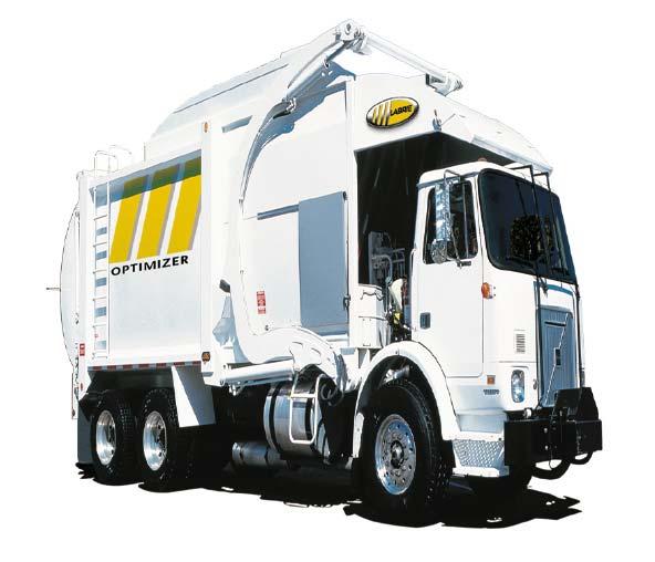
3 FOREWORD Here is the new Labrie parts and maintenance manual for the OPTIMIZER TM front loading unit. We sincerely hope that you will find it easy to use. We have designed it in a way that will allow you to easily make it available to drivers, mechanics, and to parts department personnel. Any time that you have a problem with a Labrie unit, you should contact your vendor first. He should be able to provide you with the proper help required (parts or technical advice). FIRST THINGS FIRST: DO NOT FORGET TO COMPLETE THE OWNER REGISTRATION FORM AND TO SEND IT TO LABRIE EQUIPMENT, MAKING SURE TO INDICATE IN SERVICE DATE. THIS DATE WILL BE USED TO START THE WARRANTY PERIOD. OTHERWISE, THE DATE OF DELIVERY FROM THE FACTORY WILL BE USED.
4 4 OPTIMIZER TM
5 5 OPTIMIZER TM MAINTENANCE MANUAL Table of contents 1.0 MAINTENANCE MANUAL LUBRICATION TROUBLESHOOTING SECTION OPTIMIZER BODY PARTS HYDRAULIC SYSTEMS, PARTS AND DIAGRAMS BODY AIR SYSTEMS, PARTS AND DIAGRAMS ELECTRICAL SYSTEMS DIAGRAMS AND PARTS MAINTENANCE
6 6 OPTIMIZER TM CHAPTER 1.0 Table of contents 1.0 MAINTENANCE MANUAL GENERAL SAFETY PRECAUTIONS GENERAL PRECAUTION SURFACE FINISHING AND PAINT FIRE PROTECTION LOCKOUT / TAGOUT PROCEDURE SHUTDOWN PROCEDURE PRIOR TO START UP HYDRAULIC FILTER FIRST REPLACEMENT GENERAL CLEANLINESS CLEANING THE HOPPER AREA A BODY HOISTING PROPPING PROCEDURES PACKING SYSTEM MAINTENANCE PACKING SYSTEM GENERAL MAINTENANCE PROXIMITY SWITCHES ADJUSTMENT PACKER BLADE WEAR PLATES REPLACEMENT BODY GUIDE WEAR PLATES REPLACEMENT PACKER BLADE REMOVAL PROCEDURE PACKER CYLINDERS REPLACEMENT LUBRICATION OF PACKING SYSTEM TAILGATE SYSTEM AND BODY HINGES MAINTENANCE TAILGATE LOCKING MECHANISM TAILGATE SEAL AND HINGES INSPECTION REAR BODY HINGE INSPECTION PROXIMITY SWITCHES ON TAILGATE HOPPER DOOR SENSOR ROOF PROXIMITY SWITCH FORKS AND ARMS PROXIMITY SWITCHES ARMS PARTLY RAISED PROXIMITY SWITCH PROXIMITY SWITCH ADJUSTMENT OPTIMIZER TM
7 7 OPTIMIZER TM CHAPTER 1.0 Table of contents 1.4 HYDRAULIC SYSTEM MAINTENANCE HYDRAULIC SYSTEM GENERAL INSPECTION MAIN RELIEF VALVE PRESSURE ADJUSTMENT HYDRAULIC DIRECTIONAL CONTROL VALVE PRESSURE ADJUSTMENT PROCEDURE PUMP MAINTENANCE HYDRAULIC CYLINDERS INSPECTION PROCEDURES HYDRAULIC RESERVOIR INSPECTION PROCEDURE HYDRAULIC FLUID REPLACEMENT PROCEDURE HYDRAULIC FILTER REPLACEMENT PROCEDURE HYDRAULIC STRAINER CLEANING PROCEDURE TAILGATE HYDRAULIC SYSTEM MAINTENANCE CYCLE TIME TABLE FOR ALL HYDRAULIC FUNCTIONS BODY HOISTING SYSTEM MAINTENANCE ARMS UP DECELERATION VALVE ARMS DOWN DECELERATION VALVE AIR SYSTEM MAINTENANCE AIR SYSTEM MAINTENANCE PROCEDURE MAINTENANCE
8
9 9 1.0 MAINTENANCE MANUAL 1.1 GENERAL SAFETY PRECAUTIONS GENERAL PRECAUTION CAUTION PERSONNEL IN CHARGE OF MAINTENANCE SHALL NOT PERFORM ANY MAINTENANCE ON THE EQUIPMENT WITHOUT KNOWING THE PROPER OPERATIONS OF THE EQUIPMENT AS WELL AS ALL SAFETY PRECAUTIONS OF SUCH OPERATIONS. REFER TO THE OPERATION MANUAL PRIOR TO PERFORM ANY TYPE OF WORK ON THE UNIT. CAUTION MAINTENANCE AND REPAIRS CARRIED OUT ON THIS VEHICLE, MUST BE ONLY DONE BY QUALIFIED PERSONNEL WHO ARE FAMILIAR WITH THIS EQUIPMENT. LABRIE ENVIRONMENTAL GROUP IS NOT RESPONSIBLE FOR ANY FAILURES RESULING OF REPAIRS PERFORM BY THE USER. WARNING BEFORE DOING ANY MAINTENANCE WORK ON THE VEHICLE, ALL SAFETY REGULATIONS MENTIONED IN THE OPERATOR MANUAL, MUST BE RESPECTED, ESPECIALLY THE LOCKOUT/TAGOUT PROCEDURE (ANSI Z ). For maintenance of the truck itself, please refer to the chassis maintenance manual. Only the body section and its components will be addressed in this manual. Establish and apply a periodic inspection program to keep the moving parts in good working order, properly adjusted and safe. It is recommended that a brief inspection is done by the operator EVERY DAY and that any problems or detected malfunctions is reported for correction before reusing the equipment. Once a month, inspect the chassis and the body for any breaks, cracks or possible malfunctions. Any defects found must be repaired without delay. To assure good working order of the equipment, particular attention should be paid to the deterioration of structural components due to corrosion. Touch-ups or complete paint jobs should be done when necessary. MAINTENANCE
10 SURFACE FINISHING AND PAINT Type of surface finishing recommended: PAINTING PROCEDURE Surface preparation: Grit blasting. Primary coat : Anticorrosive epoxy primer. Finishing coat:two (2) coats industrial type Imeron paint (or equivalent) FIRE PROTECTION If for any reason the maintenance personnel has to work on an equipment that has not been unloaded, for any type of work, a fire extinguisher should be made readily available close to this vehicle. Anytime a loaded vehicle is inside a garage there should be a fire extinguisher very close nearby. Inform your personnel of measures to be taken in case of a truck fire and/or a loaded body fire. In the case of a load catching on fire, inform them of an appropriate place to drop the load in the vicinity of your maintenance facility(preferably away from traffic, surface drains and ditches) LOCKOUT / TAGOUT PROCEDURE It is the employer s responsibility to follow and apply the lockout / tagout procedure for any inspection, repairs or maintenance being done on the vehicle, whether it is on the road or in the employer s garage. LOCKOUT / TAGOUT PROCEDURE Apply the parking brake. Turn the engine off. Remove the key from the ignition switch. Put the key in a safe controlled area. Tape ignition switch key hole. Turn off the master switch (If installed). Put an OFF SERVICE tag on the driver s wheel. Put an OFF SERVICE sign in the front windows. Block any system that could move by gravity with a proper easy to see safety prop (opened tailgate, etc.). Move back and forth all control handles to release any residual pressure in the system. Install blocks on both sides of wheels to prevent movement of the vehicle. Disconnect the following items if any type of welding is required: -Electronic transmission (ECU) -Electronic ABS module -Electronic engine (2 plugs on engine) -Wiper module -Battery OPTIMIZER TM
11 SHUTDOWN PROCEDURE When you park the vehicle for an extended period of time, follow the truck manufacturer requirements as well as your maintenance requirements and ensure of the following: Filler Cap HYDRAULIC TANK Safety Valve Oil Gage (Temp/Level) SHUT DOWN PROCEDURE Park on a hard level surface. Apply parking brake. Make sure that all moving parts are in the storage position (tailgate, arms and forks, packer, etc). Turn hydraulics, electricals and engine off. Turn the master switch off (if equipped). Empty air tanks. Access Panel FRONT VIEW Filter/ Breather Cap PRIOR TO START UP Before starting the vehicle ensure that no system will engage and start to operate as you are starting the engine. Every switch shall be off and the hydraulic pump disengaged. The suction valve on the hydraulic reservoir should be open (Figure #1.1). Oil Filter REAR VIEW Once the engine is started, wait for the air pressure to raise. Once the air is above 70 psi, you can then operate the equipment. FIGURE #1.1 WARNING MAKE SURE THAT THE MAIN VALVE ON THE HYDRAULIC TANK IS FULLY OPENED BEFORE STARTING THE ENGINE. IF FORGOTTEN, IMMEDIATE DAMAGE WILL BE DONE TO THE PUMP EVEN IF THE P.T.O. SWITCH IS TURNED OFF. MAINTENANCE
12 12 WARNING BEFORE STARTING THE ENGINE, MAKE SURE THAT THE SUCTION VALVE ON THE RESERVOIR IS COMPLETELY OPEN (FIGURE #1.1). IF THE VALVE IS CLOSED, IMMEDIATE DAMAGE WILL OCCUR TO THE PUMP EVEN IF THE P.T.O. SWITCH IS TURNED OFF HYDRAULIC FILTER FIRST REPLACEMENT CAUTION TO PROTECT THE NEW COMPONENTS, THE RETURN FILTER MUST BE CHANGED AFTER THE FIRST 50 HOURS OF USE. SEE HYDRAULIC FILTER REPLACEMENT PROCEDURE IN SECTION GENERAL CLEANLINESS Cleanliness is part of safety. Make sure that the equipment is kept in proper working order by removing any stacked garbage in the packer area. Keep clean all the truck lights, warning lights and safety stickers so the driver, the surrounding pedestrians and vehicles will be safe around the truck at all times CLEANING THE HOPPER AREA The area behind the packer should be cleaned every day. The packer will not work properly if the waste accumulates in this area, it could even cause severe damage to the packer and other adjacent systems. DANGER PROPERLY APPLY THE LOCKOUT/TAGOUT PROCEDURE TO PREVENT ANY ACCIDENTAL RESTARTING OF THE ENGINE. (REFER TO THE LOCKOUT / TAGOUT PROCEDURE SECTION 1.1.4) HOPPER CLEANING PROCEDURE Turn on the engine and the hydraulic system. Open the hopper roof gate. Remove the tailgate safety pins. Fully open the tailgate. A green light on the console turns on to prompt you about it. Press and hold the green button on the console to move the packer all the way to the end of its stroke. Apply the Lockout/Tagout procedure (see section 1.1.4). Open the hopper door on the right side of the body. Get in the hopper area and remove any residual material. Use a high pressure water jet to complete the cleaning. Never close the hopper door behind you while you are inside the hopper area. Get off the vehicle and close the hopper door. Back in the cab, turn on the engine and the hydraulic system. OPTIMIZER TM


13 13 HOPPER CLEANING PROCEDURE (cont d) Press and hold the yellow button on the console to retract the packer to its home position. Close the tailgate, turn off the engine, and put the safety pins back into place. DANGER ALWAYS USE THE SAFETY PROPS WHEN RAISING THE BODY. FAILURE TO DO SO WILL RESULT IN SERIOUS INJURIES OR EVEN DEATH. Close the hopper roof gate. DANGER A BOLTS THAT RETAIN THE BODY NEVER CLOSE THE HOPPER DOOR BEHIND YOU WHILE YOU ARE INSIDE THE HOPPER AREA A BODY HOISTING Some units are equippes with a body hoisting system to facilitate the maintenance under the body. If your unit is equipped with this system, perform the following steps to lift the body: BODY HOISTING PROCEDURE A. Unscrew the nuts of the 4 bolts (2 on each side) that retain the body in place. B. Make sure to remove all hoses from their supports and clamps before lifting the body in order to avoid any damages to the hoses. The clamps and supports are located under the body, near the center. C. Use the pump lever to lift the body. D. Unlock the body safety props by pulling the props locking pin. E. Put body safety props in place. B HOSE CLAMPS MAINTENANCE

14 14 CLAMPS LOCATED UNDER THE BODY, NEAR THE CENTER DANGER NEVER GO UNDER THE BODY WHEN THE SAFETY PROPS ARE NOT INSTALLED. FAILURE TO DO SO WILL RESULT IN SERIOUS INJURIES OR EVEN DEATH. USE THE PUMP LEVER TO LIFT THE BODY PUT THE BODY SAFETY PROPS IN PLACE C E SAFETY PROPS LOCKING PIN D OPTIMIZER TM
15 15 CLEANING BEHIND THE PACKER BLADE PROPPING PROCEDURES DANGER NEVER WORK UNDER, OR CLOSE TO EQUIPMENT OR ANY PART THAT IS NOT SAFELY PROPPED OR SECURED. FIGURE #1.2 HOPPER DOOR ALWAYS USETHE PROVIDED STEP LADDERS (OR ANY OTHER SAFE LADDER TO WORK TOWARDS THE FRONT) TO GET ON THE ROOF OR TO WORK ON HIGHER PARTS OF THE EQUIPMENT. REMEMBER THAT THE ROOF IS NOT MEANT TO BE WALKED UPON. BE VERY CAUTIOUS IF YOU HAVE TO WORK ON THE ROOF AREA. ALWAYS FOLLOW PROPER LOCKOUT/TAGOUT PROCEDURE (SECTION 1.1.4). The tailgate has its own safety prop system. The prop is installed when the tailgate is slightly open. The tailgate, when open, should always rest against the safety prop. DANGER ALWAYS USE THE TAILGATE SAFETY PROP WHEN WORKING UNDER A RAISED TAILGATE. PROP CAN BE INSTALLED EVEN IF THE TAILGATE HAS TO BE IN IT S FULLY RAISED POSITION. FIGURE #1.3 MAINTENANCE
16 16 TAILGATE SAFETY PROP INSTALLATION PROCEDURE Start engine. Remove tailgate safety pins. Ensure nobody is behind the vehicle. Make sure there is no garbage in body. Turn the PTO switch ON and open the tailgate about 3 feet. Remove prop lock and position the prop to it s horizontal position and align locking holes to insert locking pin and lock the prop in place (Figure #1.4). Lower tailgate so it rests on the locked safety prop. TAILGATE SAFETY PROP 1.2 PACKING SYSTEM MAINTENANCE PACKING SYSTEM GENERAL MAINTENANCE The OPTIMIZER TM packing system has an heavy duty guiding system using special hardened steel wear plates. However, because of the frequent use of the ram, we recommend that daily visual inspections be performed by the operator and weekly inspections by the maintenance personnel. Greasing all moving parts on a daily basis is very important. The proper adjustment of the proximity switches is also very important. Any problem must be corrected immediately. The factory service departement is available for any support you may require PROXIMITY SWITCHES ADJUSTMENT The proximit switches were properly adjusted at the factory. However, if the cleaning behind the packer is not performed daily, it is possible that the proximity switches will no longer stop the packer automatically. An accumulation of dirt behind the packer prevent it to retract far enough to activate the proximity switch. Also, after a certain period of time, it might be necessary to adjust the proximity switches, to prevent the cylinders from completely retracting (or extending) to the end of their stroke. TAILGATE SAFETY PROP PIN FIGURE #1.4 CAUTION YOU MUST CHECK AND CLEAN THE AREA BEHIND THE PACKER EVERY DAY! OPTIMIZER TM
17 PROXIMITY LIMIT SWITCHES ADJUSTMENT (continued) DANGER USE THE APPROPRIATE LOCKOUT/TAGOUT PROCEDURE AT ALL TIMES (SECTION 1.1.4). ADJUSTING THE PROXIMITY SWITCHES Move the packer blade about 1 inch back from the fully extended position. Adjust the proximity switch #1 so it is active (the amber light on the proximity switch should be ON) when the packer blade reaches this position. Apply the same procedure for the retracted position (proximity switch #2). Test the packer for a full cycle. Ensure that there is no knocking noise at the end of the packer cylinder strokes. PROXIMITY SWITCHES LOCATION Proximity switches FIGURE #1.5 MAINTENANCE
18 PACKER BLADE WEAR PLATES REPLACEMENT PACKER BLADE WEAR PLATES If the packer blade has a vertical movement greater than 3/16 or a side movement greater than 1/8; verify the wear plates and the body guide. We use two different types of steel for wear plates: The AR 425 and the AR 500. DANGER USE THE APPROPRIATE LOCKOUT/TAGOUT PROCEDURE AT ALL TIMES (SECTION 1.1.4). REPLACING PACKER BLADE WEAR PLATES Packer blade wear plates Remove packer blade (refer to packer blade removal procedure, Sec ) Remove the packer blade wear plates from packer blade (Figure #1.6). Verify corresponding wear plates under guiding tracks (Figure #1.7). Install new packer blade wear plates on packer blade Reinstall packer blade on unit (refer to packer blade removal procedure, Sec ). FIGURE #1.6 OPTIMIZER TM
19 BODY GUIDE WEAR PLATES REPLACEMENT BODY GUIDE WEAR PLATES DANGER USE THE APPROPRIATE LOCKOUT/TAGOUT PROCEDURE AT ALL TIMES (SECTION 1.1.4). BODY GUIDE WEAR PLATES REPLACEMENT PROCEDURE Remove the packer blade (refer to packer blade removal procedure, Sec ). Retract the packing cylinders and move them out of the way. Remove body wear plates by grinding or cutting the stitch welds attaching plates to guide. Clean surfaces and position new plates by tacking them in place. Once in proper position stitch weld plates in place. Body guide wear plates FIGURE #1.7 Reinstall packer blade. MAINTENANCE
20 PACKER BLADE REMOVAL PROCEDURE PACKER BLADE CYLINDERS REAR PINS PACKER BLADE REMOVAL PROCEDURE Start engine and hydraulic system. bring the packer to the rear end of the body to easily access the pins (Figure #1.8). Remove rear cylinder pins (Figure #1.8). Retract cylinders. Pull packer out of the body with lifting device (Figure #1.9). REAR PINS DANGER FIGURE #1.8 USE THE APPROPRIATE LOCKOUT/TAGOUT PROCEDURE AT ALL TIMES (SECTION 1.1.4). PACKER AT THE REAR END OF THE BODY FIGURE #1.9 OPTIMIZER TM
21 PACKER CYLINDERS REPLACEMENT LUBRICATION OF PACKING SYSTEM CAUTION SUPPORT THE CYLINDER TO BE REMOVED WITH PROPER LIFTING DEVICE. PACKER CYLINDER REPLACEMENT PROCEDURE Extend the packer blade completely. Remove cylinder rear pins (Figure #1.8). Retract the cylinders. Remove hoses from cylinders and front pins. Reverse procedure for installation. CAUTION BECAUSE OF IT S FREQUENT USE, THE PACKER AND IT'S ACCESSORIES MUST BE LUBRICATED EVERY WORKING DAY. Refer to the chapter 5 on lubrication for: Cylinder pins (Figure #1.10) Door hinges. DANGER USE THE APPROPRIATE LOCKOUT/TAGOUT PROCEDURE AT ALL TIMES (SECTION 1.1.4). GREASE FITTINGS Grease fittings FIGURE #1.10 MAINTENANCE
22 TAILGATE SYSTEM AND BODY HINGES MAINTENANCE It is important to lubricate the hinges and the slides for the rear door locks with multi-purpose grease. Also, inspect the welds and the proper working order of the following components (Figure #1.11 to #1.14). Tailgate hydraulic cylinders; Cylinder pins and circlips; Tailgate hinges and pins; Wear on the bearing surface of the locking machanisms Wear on the tailgate lock pins. CAUTION EXCESSIVE WEAR MIGHT BE DANGEROUS AND HARMFUL TO THE PROPER WORKING ORDER OF THE TAILGATE. TAILGATE LOCKING MECHANISM Tailgate hinges Cylinder pin TAILGATE LOCKING MECHANISM DANGER FREQUENTLY VERIFY THAT THE RETAINING RINGS (FIGURE #1.12) ARE IN PLACE TO AVOID ACCIDENTAL DROPPING OF THE TAILGATE. Tailgate locking mechanism Tailgate lock pins Locking mechanism Retaining ring Safety lock pin FIGURE #1.11 FIGURE #1.12 OPTIMIZER TM
23 TAILGATE SEAL AND HINGES INSPECTION The hinge pins must not have any signs of excessive wear or metal fatigue. The retaining bolts must be kept tight (Figure #1.15). Perform a visual inspection of the rubber seal along the rim of the tailgate. Replace any broken components necessary REAR BODY HINGE INSPECTION Monthly lubrication of the body and chassis hinges should be done (Figure #1.13). Also, inspect for cracks or corrosion. Any eventual cracks must be reported, recorded and repaired by qualified personnel PROXIMITY SWITCHES ON TAILGATE The unit has a proximity switch that activates the back-up alarm and a warning buzzer (inside the cab) to tell the operator that the tailgate is unlocked (Figure #1.15). A proximity switch (Figure #1.14), mounted on top of the body will engage a light on the console to warn the operator that the tailgate is fully opened. Verify the proper working order and adjustment of those two limit switches. PROXIMITY SWITCH FOR UNLOCKED TAILGATE CHASSIS HINGE FIGURE #1.13 PROXIMITY SWITCH FOR FULLY RAISED TAILGATE Limit switch Tailgate Proximity switch FIGURE #1.14 FIGURE #1.15 MAINTENANCE


24 HOPPER DOOR SENSOR The hopper door is equipped with a limit switch that detects if the side door is open. On some units, this task is performed by a proximity switch instead (optional). When the hopper door is open, the pump can not be engaged. That way, it is impossible to use the packer or any hydraulic system. The forks MUST be completely fold to avoid any collision and to respect the size limitations applicable in your area. PROXIMITY SWITCH THAT DETECTS IF THE ARMS ARE PARKED Verify the proper working order and adjustment of this limit /proximity switch. DANGER NEVER ENTER THE HOPPER AREA WHEN THE ENGINE IS RUNNING AND THE HYDRAULIC PUMP IS ENGAGED ROOF PROXIMITY SWITCH There s aproximity switch that detects if the roof is open or closed. If the roof is closed, it is impossible to start the packer. That way, you will avoid damages to the body. Also, the roof MUST be open to raise the arms. If the roof is closed, it won t be possible to raise the arms in order to avoid debris falling on the roof. FORKS FULLY TILTED PROXIMITY SWITCH FORKS OVERHEAD WARNING LIGHT FORKS AND ARMS PROXIMITY SWITCHES Some units are equipped with proximity switches that indicate if the arms and forks are fully parked and fold. One is located on the arms axle and the other one is located on the forks axle (on right-hand side). If the forks are not fold when the arms are raising and reaching a certain point, the Forks Overhead warning light comes ON on the dashboard. OPTIMIZER TM

25 ARMS PARTLY RAISED PROXIMITY SWITCH Some units are equipped with a proximity switch that allows the operator to raised the arms when the packer is retracting. If the packer is not completely retracted when the arms pass in front of the proximity switch, the arms stop to avoid debris falling on the packer or behind it. The operator will have to wait until the packer is completely retracted before raising the arms further. If the truck is equipped with this proximity switch, it is located on the left-hand side of the arm torque tube. ARMS PARTLY RAISED PROXIMITY SWITCH LOCATION (IF EQUIPPED) CAUTION MAKE SURE THAT ALL THE PROXIMITY SWITCHES ARE WELL ADJUSTED AND THAT THEY ARE WORKING PROPERLY PROXIMITY SWITCH ADJUSTMENT Here is a general procedure to adjust the proximity switches: GENERAL PROXIMITY SWITCH ADJUSTMENT PROCEDURE Park the truck on a safe and level ground. Apply the parking brake and make sure that the truck is tagged out for maintenance (see Lockout/Tagout section of the Operator Manual). Start the engine and engage the hydraulic pump. Shut off the engine and turn off the hydraulic pump. Unscrew the nuts located on each side of the proximity switch. Move the proximity switch laterally until there s a gap of 1/8 inch between the proximity switch and its target. Screw the nuts of the proximity switch. Start the engine and engage the hydraulic pump. Perform tests to make sure that the proximity switch works properly. MAINTENANCE
26 HYDRAULIC SYSTEM MAINTENANCE HYDRAULIC SYSTEM GENERAL INSPECTION Filler cap HYDRAULIC TANK PARTS Filter/ breather HYDRAULIC SYSTEM GENERAL INSPECTION PROCEDURE For new equipment, change the return element filter after 50 hours of use, and every 500 hours thereafter. See hydraulic filter replacement procedure section 1.4.9; Clean the strainer inside the reservoir after the first 50 hours of use and yearly thereafter (Figure #1.16). See hydraulic strainer cleaning procedure, sec ; When maintenance is carried out, protect the hoses from any dirt that would eventually get into the oil; Periodically inspect and adjust the oil pressure in the hydraulic system as follows: 2500 PSI +/- 25 RPM RPM; idle speed); Frequently inspect the hydraulic lines and connections for leaks, correct if necessary; The suction valve on the reservoir must be fully open (Figure #1.1) before starting the engine; Filter FIGURE # MAIN RELIEF VALVE PRESSURE ADJUSTMENT A hydraulic oil pressure verification must be performed every month. The relief valve is preset to 2500 PSI +/- 50 PSI at 1500 RPM by the manufacturer. If the pressure is not within this preset adjustment, the pressure relief valve must be readjusted. CAUTION ADJUSTING THE MAIN RELIEF VALVE AT HIGHER PRESSURE THAN 2500 PSI WILL CREATE EXTENSIVE DAMAGE AND VOID THE MANUFACTURER S WARRANTY. OPTIMIZER TM
27 HYDRAULIC DIRECTIONAL CONTROL VALVE The OPTIMIZER is equipped with a Parker directional control valve, model VG-35. The hydraulic valve controlling all the functions of the front loader refuse body is assembled as follows: (from bottom to top as positioned on the truck). Sliding roof: 4 ways, 3 positions, operated with an air actuator. Forks: 4 ways, 3 positions, operated with an air actuator. Arm: 4 ways, 3 positions, operated with an air actuator. Packer: 4 ways, 3 positions, operated with an air actuator. Tailgate: 4 ways, 3 positions, operated with an air actuator. For further details, refer to the hydraulic system parts and diagram, or see the simplified diagram for the packing system in the troubleshooting section. MAIN HYDRAULIC VALVE Quick-coupling Tailgate Arms Forks Packer Sliding roof FIGURE #1.17 MAINTENANCE

28 PRESSURE ADJUSTMENT PROCEDURE PRESSURE ADJUSTMENT PROCEDURE Install a 3000PSI pressure gauge on the quick coupling found on the main valve (Figure #1.17). Start the engine and engage the hydraulic system. Maintain the engine speed at 1500 RPM PUMP MAINTENANCE The hydraulic pump on the OPTIMIZER TM is a gear pump type equipped with a Muncie live pack pump (Figure #1.18). If the pump is properly maintained, it will provide a satisfactory output. If the pump is noisy, carry out the following inspections: Open the tailgate until the mechanism reaches the end of its stroke. Check the pressure while the tailgate is held fully open. The pressure reading shall be within 2450 and 2550 PSI. Adjust the main relief if necessary (Figure #1.17). Loosen the lock-nut and turn the adjustment knob clockwise to increase the pressure and counterclockwise to reduce the pressure. FIGURE #1.18 DANGER USE THE APPROPRIATE LOCKOUT/TAGOUT PROCEDURE AT ALL TIMES (SECTION 1.1.4). OPTIMIZER TM
29 HYDRAULIC CYLINDERS INSPECTION PROCEDURES To maintain proper working order and prolonged cylinder performance, it is essential to inspect them at least once a week as recommended. Verify that all the connections of the flexible hoses and pipes are tight, and that there are no external leaks. Check that all the cylinder head cap screws are firmly tightened and that there are no leaks. All leaks must be corrected immediately by replacing damaged or worn seals with new ones. Lubricate and inspect all the cylinder mounting points (pins, retaining bolts, etc.) HYDRAULIC RESERVOIR INSPECTION PROCEDURE Verify that the oil in the reservoir is clean and always at the proper level. HYDRAULIC RESERVOIR MAINTENANCE PROCEDURE For increased longevity, clean the strainer inside the reservoir after the first 50 hours of service and annually thereafter (Figure #1.16). Verify the cleanliness of the filler cap (NOT BLOCKED, Figure #1.16). Verify the cleanliness, the color and the level of the hydraulic oil. (level at 3/4 of the oil level gauge, with all cylinders retracted). CAUTION MAXIMUM TEMPERATURE FOR HYDRAULIC FLUID IS 180 F, +/- 10 F The maximum temperature for the system should not exceed 180 F +/- 10 F. Refer to the hydraulic parts section (Chapter 8) for parts numbers. MAINTENANCE

30 HYDRAULIC FLUID REPLACEMENT PROCEDURE CAUTION HIGHLY CONTAMINATED HYDRAULIC FLUID MUST BE CHANGED TO AVOID ANY DAMAGE ON THE SYSTEM. CAUTION IT IS NOT RECOMMENDED TO MIX DIFFERENT TYPES OF OIL IN THE SAME RESERVOIR. CAUTION VERIFY THAT THE BALL VALVE ON THE SUCTION IS COMPLETELY OPEN BEFORE ENGAGING THE HYDRAULIC SYSTEM (FIGURE #1.1). 3. Retract all cylinders (Packer, crusher panel, tailgate etc.). 4. Disengage the hydraulic pump and stop the engine. 5. Use a clean container of at least 60 gallons to drop the old oil into. 6. To drop the oil, close the ball valve and remove the drain plug under the tank. Use a container with a minimum capacity of 60 US gallons to collect the oil. 7. Completely drain the tank. 8. Once emptied, reinstall the drain plug. 9. Remove the strainer (Figure #1.19) by removing the bolts and clean it (once a year). CAUTION AFTER THE FIRST 50 HOURS, CHANGE THE RETURN FILTER ONCE AGAIN. STRAINER HYDRAULIC OIL REPLACEMENT PROCEDURE 1. Ensure that the parking brake is applied and the vehicle is tagged out for maintenance purposes (refer to the section Lockout/Tagout procedure ). FIGURE # Start the engine, engage the hydraulic pump and disable the speed-up system. OPTIMIZER TM
, insert the hand in the hole where the strainer was fixed. This allows to clean one half of the tank.")
31 31 HYDRAULIC OIL REPLACEMENT PROCEDURE (Cont d) 10. Clean inside the hydraulic tank with a clean and dry cloth in order to remove any metal particles or debris accumulated at the bottom. To clean the interior of the an aluminum tank (cylindrical), insert the hand in the hole where the strainer was fixed. This allows to clean one half of the tank. To clean the other half, remove the entire filter at the rear side of the tank, insert the hand inside, and clean with the cloth. To clean the steel tank (Figure # 1.16), remove the access panel by removing the retaining screw. Insert the hand inside and clean the interior with the dry and clean cloth. 13. The oil must be clean and free of any dirt, metallic particles or sand etc.) The use of a filtering screen is strongly recommended while filling the tank with new oil. 14. If the suction line has been replaced, fill the line until the oil reaches the pump to avoid cavitation (see section 3.1 of Troubleshooting). 15. Start the engine and check again. 3/4 OF OIL LEVEL GAUGE OIL GAUGE AND TEMPERATURE 11. Change the return filter element (twice a year). 12. Refill the tank until oil reaches the 3/4 of the oil gauge (Figure #1.20). Use a high quality oil, that has good performance in cold weather(if applicable), such as SHELL TELLUS T32 or equivalent (See Lubrication section for specifications). The whole system will require between 50 and 60 gallons. FIGURE #1.20 MAINTENANCE
32 HYDRAULIC FILTER REPLACEMENT PROCEDURE To protect the components, the return filter must be changed after the first 50 hours of use. Then the return filter must be changed once a year. For part numbers refer to the hydraulic parts table. For replacement proceed as follow: HYDRAULIC FILTER REPLACEMENT PROCEDURE Shut off the hydraulic system and truck engine; Shut off the ball valve on the suction line (Figure #1.1). Remove the filter head s four retaining bolts (Shroeder type) or front cap (Pall type) (Figure #1.16). Replace the filter element with a new one, compatible with the manufacturer's recommendations. Refer to hydraulic parts section. When replacing an in-tank filter be ready to recuperate 2 gallons of oil approximately. An in-tank return filter system has a self-closing valve preventing the whole tank to empty itself through the return filter core HYDRAULIC STRAINER CLEANING PROCEDURE HYDRAULIC STRAINER REPLACEMENT PROCEDURE Shut the engine off and let the hydraulic oil to cool down. Clean around the filler cap and remove it. Use a clean container of at least 60 gallons to drop the old oil into. Once the tank is empty, replug the drain valve. Shut the drain valve off and remove suction hose from ball valve. Remove the strainer from tank port. Clean the strainer and perform a visual inspection for any damage. Replace at once if necessary. A DAMMAGED STRAINER COULD RESULT OF EXTENSIVE DAMAGE TO THE PUMP. Refer to hydraulic fluid replacement procedure for filling the tank back up. OPTIMIZER TM
33 TAILGATE HYDRAULIC SYSTEM MAINTENANCE The OPTIMIZER TM units are equipped with a special hydraulic system that controls the locking mechanism of the tailgate. If the continuous re-locking system is not working properly: tailgate unlocks by itself or if the tailgate is dropping from the fully open position by itself refer to section 6.4 for troubleshooting CYCLE TIME TABLE FOR ALL HYDRAULIC FUNCTIONS FUNCTIONS Packer blade: Tailgate: Sliding roof: Lifting arm: Forks: ENGINE RPM : 1500 CYCLE TIME 22 sec 45 sec 15 sec 15 sec 5 sec BODY HOISTING SYSTEM MAINTENANCE The OPTIMIZER TM is equipped with a hoisting system used to raised the body. This system is fed by its own hydraulic pump (see Figure #1.21. Since this pump is energized by electrical cables, it is protected by a cover. CAUTION ALWAYS BE EXTREMELY CAREFUL WHEN WORKING NEAR THE PUMP ELECTRICAL TERMINALS. FAILURE TO DO SO MAY RESULT IN SERIOUS INJURIES, ELECTROCUTION OR EVEN DEATH. The pump of the body hoisting system must be adjusted to 2000 PSI. To do so, proceed with the following steps: Packer ejection mode: Extend Retract 24 sec 10 sec BODY HOISTING SYSTEM PUMP ADJUSTMENT Install a 3000PSI pressure gauge on the quick coupling found on the pump (see Figure #1.21). By using the pump manual lever (see Figure #1.22), raise the body until the mechanism reaches the end of its stroke. Check the pressure while the body is held fully raised. MAINTENANCE
.")
34 BODY HOISTINGSYSTEM MAINTENANCE(cont d) BODY HOISTING SYSTEM PUMP ADJUSTMENT (CONT D) The pressure reading shall be at 2000 PSI. Adjust the relief if necessary. Turn the adjustment clockwise to increase the pressure and counterclockwise to reduce the pressure (see Figure #1.21). QUICK COUPLING The hoisting system is also equipped two body safety props, which MUST be used each time the body is raised. These safety props MUST be lubricated properly to ensure their efficiency. To used the safety props, do the following steps: HOW TO USE BODY SAFETY PROPS Raise the body by using the manual lever on the body lifting system pump (see Figure #1.22). Unlock the safety props by pulling on the safety props locking pin (located on the right-hand side; see Figure #1.23). Pull down the safety prop (the other one will lower automatically) and place it on its support (see Figure #1.24). ADJUSTMENT SCREW LOCKING PIN FIGURE #1.21 PUMP MANUAL LEVER FIGURE #1.23 DANGER FIGURE #1.22 ALWAYS USE THE SAFETY PROPS WHEN WORKING UNDER THE BODY. FAILURE TO DO SO MAY CAUSE SERIOUS INJURIES OR EVEN DEATH. OPTIMIZER TM
 BOTTOM GREASING POINT SAFETY")

.")


35 BODY HOISTING SYSTEM MAINTENANCE(cont d) BOTTOM GREASING POINT SAFETY PROPS SAFETY PROP SUPPORT FIGURE #1.24 FIGURE #1.24 To lubricate the body safety props, apply the recommended grease through the greasing points, which are located near the safety props shaft, inside the rails (see Figure #1.25). There are a greasing point on each side. TOP GREASING POINT FIGURE #1.25 SAFETY PROP GREASING POINT TOP OF CYLINDER FIGURE #1.25 The hoisting system also needs to be lubricated properly. The greasing points are located on each hoisting system cylinder. One is located at the bottom of the cylinders and the other one is located at the top of the cylinders (see Figures #1.26 and 1.27). BOTTOM OF CYLINDER FIGURE #1.26 MAINTENANCE


36 ARMS UP DECELERATION VALVE The arms up deceleration valve automatically decelerates the arms as they are raised to the dump position. A cam bolted to the arm pivot tube rotates as the arms are raised and gradually depresses the valve spool, reducing the flow of oil exiting the tube end of the arm cylinders. NOTE: The deceleration valve greatly reduces impact on the arm assembly, body structure, and hydraulic components. Location: Fitted to the underside of the body, behind the arm pivot tube on the curbside. Adjustment procedure 1. Remove the cap on the cushioning adjustment screw located on the armscylinder and unscrew completely (see Figures 1.27 and 1.28). 2. Raise the arms up until they rest on the arm stops. 3. Position the cam so there is 4 inches between its boss and the body (see Figure #1.29). 4. Tighten the retaining bolts of the cam. 5. Lower and raise the arms while running the engine at idle speed and again while running the engine at 1500 RPM. NOTE: The arms should slow when they are approximately 18 in. (45.72 cm) away from the arm stops and gently come to rest against the arm stops. 6. If the arms reach the stops with jarring impact or the arms stop before reaching the arm stops: a. Loosen one retaining bolt and tap the cam in the required direction. b. Tighten the retaining bolt of the cam and repeat step Attach a container to the forks and repeat steps 5 and Remove the container from the forks and repeat steps 6 and 7 until the arms decelerate with an without a container on the forks. 9. Tighten the locking setscrew. CUSHIONING ADJUSTMENT SCREW FIGURE #1.27 ADJUSTMENT SCREW WITHOUT CAP FIGURE #1.28 OPTIMIZER TM


37 37 4 BETWEEN CAM BOSS AND BODY BODY CAM BOSS DECELERATION VALVE PLUNGER FIGURE #1.29 DECELERATION VALVE CAM BOSS FIGURE #1.30 FIGURE #1.31 MAINTENANCE


38 ARMS DOWN DECELERATION VALVE Some units are equipped with an arms down deceleration valve. This deceleration valve automatically decelerates the arms as they are lowered. A cam bolted to the arm pivot tube rotates as the arms are lowered and gradually depresses the valve spool, reducing the flow of oil exiting the shaft end of the arm cylinders. NOTE: The deceleration valve greatly reduces impact on the arm assembly, body structure, and hydraulic components. Location: Fitted to the underside of the body, behind the arm pivot tube on the streetside. 6. Attach a container or carry can to the forks and repeat steps 4 and 5 without a container on the forks. 7. Remove the container from the forks and repeat steps 5 and 6 until the arms decelerate with and without a container on the forks. 8. Tighten the locking setscrew. 8 BETWEEN CAM BOSS AND BODY Adjustment Procedure 1. Lower the arms down as far as possible. 2. Position the cam so there is 8 inches between its boss and the body (see Figure #1.32). 3. Tighten the retaining bolts of the cam (see Figure #1.33). 4. Raise and lower the arms while running the engine at idle speed and again while running the engine at 1500 RPM. NOTE: The arms should slow when they are at approximately 18 in. (45.72 cm) away from being fully lowered and gently come to rest at the bottom of their travel. 5. If the arms reach the bottom of their travel with jarring impact of the arms stop before being fully lowered: a. Loosen the retainig bolt. b. Tap the cam in the required direction. c. Tighten the retaining bolt of the cam and repeat step 4. CAM BOSS FIGURE #1.32 CAM RETAINING BOLTS OPTIMIZER TM
39 AIR SYSTEM MAINTENANCE AIR SYSTEM MAINTENANCE PROCEDURE Air system is crucial for the brakes to operate with maximum efficiency. All air tanks on the chassis must be drained after each working day. Some units are equipped with an air dryer and/or alcohol evaporator. These devices are used to reduce water in the air system, preventing air components to corrode or to freeze in cold weather. To perform maintenance on the air dryer and alcohol evaporator, refer to the chassis manufacturer maintenance manual. To avoid loss of air control on packer blade (especially under cold/wet weather conditions), we strongly recommend to check the following items: AIR SYSTEM MAINTENANCE PROCEDURE Ensure that the parking brake is applied and the vehicle is tagged out for maintenance purposes (refer to the section Lockout/Tagout procedure ). Drain all the air tanks daily. Change absorbant material in the air dryer twice a year: On this type of equipment the compressor works all the time (Frequent use of break system). As a consequence, a lot of moisture is injected into the air system. See chassis manufacturer recommandations. Twice a year, lubricate the air actuator and solenoid valve found on the main valve with light (low temperature) oil. MAINTENANCE
40 40 OPTIMIZER PREVENTIVE MAINTENANCE CHART COMPONENT/SYSTEM SERVICE/CHECK 1.0 Hydraulic system 2.0 Cleaning of hopper area 3.0 Perform a visual inspection of the following components: 4.0 Body and chassis X Check for corrosion * Replace return filter after the first 50 hours of operation MAINTENANCE MANUAL SECTION WEEKLY YEARLY X Check oil level in tank and refill if necessary Check if ball valve is open on tank Check on ground for overnight leaks Check cylinders, pump control valve and system for leaks. Repair/replace if required. Replace hydraulic filter * Drain oil, clean strainer and refill Check pressure Open hopper trap on right hand side Hydraulic cylinders and cylinder pins, hoses, pipes and hydraulic connections, wear of floor and side of hopper DAILY EVERY 2 MONTHS X X X X X X X X Clean under and behind the packer blade X OPTIMIZER TM
41 41 MAINTENANCE
42 COMPONENT/SYSTEM Proximity switches Greasing and lubrication Light and wiring Controls inside the cab/ on the side of the unit Air tanks Pneumatic system Safety systems OPTIMIZER PREVENTIVE MAINTENANCE CHART SERVICE/CHECK Proper adjustment of proximity switches Check and clean area around proximity switches Packer and its accessories (See lubrication chart on side of the truck Apply light grease if required Check for proper operation Check for proper operation Drain Check for leaks Check for proper operation (tailgate alarm,safety prop warning light ect...) MAINTENANCE MANUAL SECTION WEEKLY EVERY 2 MONTHS YEARLY X DAILY Grease fittings X X X X X X X X OPTIMIZER TM
43 43 LUBRICATION
44 44 LABRIE OPTIMIZER CHAPTER 2.0 Table of contents 2.0 LUBRICATION RECOMMENDED LUBRICANT HYDRAULIC FLUIDS MOTOR OIL FOR VEHICLE GREASE OPTIMIZER TM
45 45 LUBRICATION
46 LUBRICATION 2.1 RECOMMENDED LUBRICANT HYDRAULIC FLUIDS Minimum requirement for hydraulic oil: Viscosity of 320 cst at 104 o F (40 o C) and 6.4 cst at 212 o F (100 o C). Must contain anti-wear, and anti-foam additives, rust and oxidation neutralizers and self protecting agents MOTOR OIL FOR VEHICLE Refer to chassis manufaturer s maintenance manual GREASE Any lithium-base commercial multi-purpose grease may be used. *For Nordic regions Shell Tellus T32 is strongly recommended. Must meet MIL-H-5606 or SAE IOW MS standards. The following oils may be used in the Optimizer. Shell Tellus 32 or T-32 CAUTION DO NOT MIX DIFFERENT BRAND OF OILS IN DOUBT DRAIN AND REFILL WITH NEW OIL. The hydraulic tank has a maximum capacity of 81 US gallons or 300 litres. FILL THE HYDRAULIC TANK TO 80% OF ITS FULL CAPACITY(Around 65 US Gallons or 240 liters) IN ORDER TO PREVENT OIL SPILL. Refer to section 4. OPTIMIZER TM
47 47 LUBRICATION

48 48 LUBRICATION CHART ON SIDE OF THE TRUCK OPTIMIZER TM
49 49 TROUBLESHOOTING
50 50 LABRIE OPTIMIZER CHAPTER 3.0 Table of contents 3.0 TROUBLESHOOTING SECTION TROUBLESHOOTING TABLE INTERNAL LEAK DETECTION FOR CYLINDERS TAILGATE LOCKING MECHANISM TROUBLESHOOTING MAIN HYDRAULIC SCHEMATIC OPTIMIZER TM
51 51 TROUBLESHOOTING
52 TROUBLESHOOTING SECTION 3.1 TROUBLESHOOTING TABLE Important: at all times when troubleshooting refer to the corresponding sections. PROBLEMS POSSIBLE CAUSES REMEDY Insufficient packing ratio 1. Low oil pressure 1. Check if oil pressure at relief valve is 2500 PSI or Faulty hydraulic pump (cavitation or wear). 2. The packer hydraulic cylinders are internally by-passing 2. See section Wrong method of loading waste or type of waste 3. See Operator Manual) Hydraulic oil is over heating(more than 77 C, + or - 4 C,180 For more,+ or - 10 F.) 1. Faulty pump or faultyrelief valve 2. NOT THE PROPER GRADE OF OIL. ie. :Too thin in hot temperatures or too thick in cold temperatures. 3. Hydraulic pressure is too high 4. Oil level in reservoir too low 5. Contaminated oil 1. When the hydraulic oil is cooled off, turn on hydraulic system and work the packer for 2 or 3 minutes.then touch the pump and relief valve. If they are faulty, they will be much hotter than the other components on the hydraulic system. 2. See section 2.0 for proper oil to use. 3. Set the pressure at the relief valve to 2500 PSI 4. Add oil to required level 5. Clean the suction strainer, replace the return filter and change oil. Oil foaming 1. Air getting into the system 2. Not the proper grade of oil hydraulic oil 1. Tighten the connections through the hose between the pump and the reservoir 2. Empty oil and refill with antifoam 3. Low oil level 3. Refill the reservoir OPTIMIZER TM
53 TROUBLESHOOTING TABLE (continued) PROBLEMS POSSIBLE CAUSES REMEDY Cavitation, excessive noise from the pump 1. Low oil level 1. Refill the reservoir 2. Oil too thick 3. Dirty strainer 2. Change oil for an appropriate grade of oil according to the ambiant temperature. 3. Clean and/or change the strainer. 4. Suction hose blocked 4. Unblock the hose. 5. Ball valve partly closed 5. Open the valve completely The diaphragm (wear end plate) and/or pump casing and/or gear teeth have grooves on them (Do not take apart a pump that is still covered by warranty). 1. Abrasive wear caused by small particles. 2. Invisible miniature particles. 1. Have the strainer, return filter canister been changed as required? 2. Is the hydraulic oil clean? 3. After any repairs was the hydraulics properly cleaned? Blue or black valve diaphragm. Pump casing is cracked. 1. Oil overheating more than 77 C (180 o F). 2. Over pressure. 1. Check to see if the suction on the reservoir is opened. 2. Check if the relief valve is working properly. TROUBLESHOOTING
54 TROUBLESHOOTING TABLE (continued) PROBLEMS POSSIBLE CAUSES REMEDY Excessive vertical or as sideway of the packer blade. 1. The packer wear plates have too much wear. 1. Inspect the wear plates as movement (sec 1.0) and replaced if necessary. Pump will not engage, the packer will not work. Packer blade will not push the load out. 1. The red (stop) push button wasvolontary or accidentaly depressed. 2. Hopper door open 1. The tailgate is not fully opened. 2. Tailgate fully opened limit switch faulty or out of adjustment. 1. Fix problem if any prior to lift the red(stop) push button. 1. Open the tailgate completly. 2. Adjust or replace the limit switch. Packer blade is not working when pressing the green button 1. No electrical power reaches the solenoid valve 1. Check for power source on the solenoid valve (located in the console). 2. Check for melted fuses. 2. Solenoid valve is faulty. 2. The faulty selenoid must be replaced. OPTIMIZER TM
55 INTERNAL LEAK DETECTION FOR CYLINDERS An internal leak is caused by a damaged seal inside the hydraulic cylinder. Because the cylinder is leaking oil inside (bypassing), a certain amount of pressure is lost reducing the cylinder efficiency and its capacity to push or pull. If the packer cylinders are bypassing, the seal inside the cylinder may require to be replaced. If an internal leak is suspected, apply the following procedure to verify it: INTERNAL LEAK DETECTION FOR CYLINDERS INTERNAL LEAK DETECTION FOR CYLINDERS A 1. Apply all safety measures to ensure safety around the vehicle at all times. 2. Ensure that the parking brake is applied. 3. Pull out the Emergency Stop Button (red). 4. Start the engine and engage the hydraulic pump. 5. Fully extend the packer cylinders. 6. Disengage the hydraulic pump. 7. Disconnect the hose at end A. 8. Plug the end of the disconnected hose. 9. Put pressure on the piston end. 10. If oil leaks out of end A, there is an internal leak. Replace damaged parts FIGURE #3.1 A TROUBLESHOOTING
56 TAILGATE LOCKING MECHANISM TROUBLESHOOTING The tailgate locking mechanism is equipped with hydraulic safety systems that prevent accidental unlocking of the tailgate during operation. One of the systems is the velocity fuse with the power bleed and the other is the holding valve. The spool inside the tailgate section of the valve is designed in such a way, that it will allow pressure to pass through it each time the pressure is building up in the hydraulic system (i.e.: when the packer is working). The pressure burst goes to the holding valve into port D1 and then out to the cylinder by port U1. This will keep the tailgate cylinders pressurized and the tailgate closed when packing material. The velocity fuse, located on the valve (Figure #3.3), will make sure to drain any slow moving oil coming from the piston side of the tailgate cylinders. Since the rod side is being pressurized with the Power bleed system, the other side has to drain to avoid any pressure build-up. The velocity fuse makes the piston side open to tank when the oil is moving under 3 gallons per minute and will shut when a flow signal is sent. NOTE: Refer to the main hydraulic schematic. Holding valve Tailgate Port D2 Port U2 Port D1 Port U1 FIGURE #3.2 OPTIMIZER TM
57 57 Gauge port Gauge 2 Main relief Velocity fuse Gauge 1 FIGURE #3.3 TROUBLESHOOTING


58 TAILGATE LOCKING MECHANISM TROUBLESHOOTING (cont d) Problem #1: Tailgate is UNLOCKING by itself If the tailgate seems to unlock by itself when using the packer, the power bleed inside the valve might not work on the right side of the hydraulic cylinder. Apply the following procedure: 8. If gauge #1 indicates pressure, this may be caused by a faulty holding valve, faulty velocity fuse or hydraulic hoses not properly connected. Refer to the main hydraulic schematic for proper connection. TAILGATE HYDRAULIC TROUBLESHOOTING Gauge 1 1. Apply all safety measures to ensure safety around the vehicle at all times. 2. Ensure that the parking brake is applied. 3. Pull out the Emergency Stop Button. 4. Install a pressure gauge on each port of the tailgate section on the valve, as shown on figures # 3.3, 3.4 and 3.5. FIGURE # Start the engine and engage the hydraulic pump. 6. Lift the forks completely to pressurize the system. 7. Gauge #1 should always indicate 0PSI and gauge #2 should indicate a sudden pressure burst between 0 PSI to 3000 PSI each time the packer reaches the end of a stroke. Gauge 2 FIGURE #3.5 NOTE: The figures above show only the places where to install the gauges. To install these gauges, use appropriate fittings. OPTIMIZER TM
59 59 Problem #2: Tailgate is LOWERING by itself REAR TAILGATE One other problem that may be found on the tailgate hydraulic system is that it would lower by itself. A faulty velocity fuse might be involved. Apply the procedure below in order to verify and /or replace the velocity fuse. TAILGATE HYDRAULIC TROUBLESHOOTING 1. Apply all safety measures to ensure safety around the vehicle at all times; 2. Ensure that the parking brake is applied; 3. Remove the velocity fuse (Figure #3.3) and verify that it is clean and that the plunger is moving freely. A new velocity fuse may be necessary. REAR TAILGATE SAFETY PIN TROUBLESHOOTING
60 MAIN HYDRAULIC SCHEMATIC OPTIMIZER TM
61 61 Intentionally left blank TROUBLESHOOTING
62 62 LABRIE OPTIMIZER CHAPTER 4.0 Table of contents 4.0 HYDRAULIC SYSTEMS PARTS AND DIAGRAMS HYDRAULIC HOSES AND PIPES ON CHASSIS HOW TO ORDER HYDRAULIC PIPING TANK TO PUMP (PETERBILT A320 4*2) PUMPS, VALVES AND HYDRAULIC TANK HYDRAULIC TANK MUNCIE HYDRAULIC PUMP MAIN VALVE...71 OPTIMIZER TM
63 63 HYDRAULIC
64 HYDRAULIC SYSTEMS PARTS AND DIAGRAMS 4.1 HYDRAULIC HOSES AND PIPES ON CHASSIS HOW TO ORDER When ordering hydraulic components, always specify the following: a) Body serial number: eg. FL98HHA b) Type of body 40 cubic yards This capacity determines the length of the body therefore the type of hydraulic pipes, hoses, hoists and pumps. c) Type of pump Muncie Live Pack Denison Vane Pump d) Type of chassis with wheel configuration, eg. Peterbilt A320 6x4 e) Type of transmission, eg. Allison MD3560 OPTIMIZER TM
65 HYDRAULIC PIPING TANK TO PUMP (PETERBILT A320 4*2) HYDRAULIC
66 HYDRAULIC PIPING TANK TO PUMP (PETERBILT A320 4*2) NO. PART NO. DESCRIPTION QTY RAIL, TUBE HOLDER TANK RETURN HOSE PUMP RETURN HOSE DRAIN VALVE HOSE PUMP SUCTION HOSE SUCTION TUBING SUPPORT, HYDRAULIC TUBING ASSY BODY RETURN HOSE SUPPORT, HYDRAULIC TUBING ASSY TANK SUCTION HOSE PACKER RETURN HOSE SUPPORT HYDRAULIC HOSE HYDRAULIC HOSE HYDRAULIC HOSE, PUMP PRESSURE HYDRAULIC HOSE, BODY PRESSURE SUPPORT SUPPORT HYC CLAMP HYF06280 T FITTING HYS CLAMP HYS HOSE SUPPORT HYS HOSE SUPPORT HYS HOSE SUPPORT... 3 OPTIMIZER TM
67 PUMPS, VALVES AND HYDRAULIC TANK HYDRAULIC TANK HYDRAULIC
68 HYDRAULIC TANK NO. PART NO. DESCRIPTION QTY ADAPTOR SUCTION VALVE ASSY HYDRAULIC TANK CIB00061 TANK CAP HYF02157 ADAPTOR REDUCED HYF DEGREE FITTING HYF06275 T FITTING HYF DEGREE FITTING HYF08810 ADAPTOR REDUCED HYF20015 SCHROEDER RETURN FILTER HYF20025 FILTER SEAL HYF20162 BREATHER-FILTER HYJ00150 OIL GAUGE PNF07605 CAP... 3 OPTIMIZER TM
69 MUNCIE HYDRAULIC PUMP NOTE: FITTINGS VARY ACCORDING TO TRUCK CONFIGURATION. HYDRAULIC
70 MUNCIE HYDRAULIC PUMP NO. PART NO. DESCRIPTION QTY SPECIAL FITTING HYF00095 SPLIT FLANGE HARDWARE) HYF07870 HYDRAULIC FITTING HYF DEGREE FITTING HYF13800 FITTING HYF25015 ADAPTOR HYP01175 MUNCIE LIVE PACK PUMP HYS02500 TYRONE ADAPTOR QUB00700 BOLT QUY00200 YOKE WITH FLANGE QUY00400 YOKE FOR PUMP SUD00412 DRIVING SHAFT... 1 OPTIMIZER TM
71 MAIN VALVE HYDRAULIC
72 MAIN VALVE NO. PART NO. DESCRIPTION QTY ADAPTOR HYF ADAPTOR HYF04686 ADAPTOR HYF05000 ADAPTOR HYF05075 ADAPTOR HYF05118 ADAPTOR HYF ADAPTOR HYF ADAPTOR HYF05185 ADAPTOR HYF ADAPTOR HYF ADAPTOR HYF ADAPTOR HYF ADAPTOR HYF10050 SAFETY CAP HYF10200 QUICK CONNECT HYF11150 FITTING HYV05110 VG-35 5-SECTION PNEUMATIC VALVE PNF02850 PNEUMATIC FITTING PNF ADAPTOR... 5 OPTIMIZER TM
73 73 Intentionally Left Blank HYDRAULIC
74 74 LABRIE OPTIMIZER CHAPTER 5.0 Table of contents 5.0 BODY AIR SYSTEMS, PARTS AND DIAGRAMS INTRODUCTION GENEREAL PNEUMATIC DIAGRAM BODY AIR SYSTEMS
75 BODY AIR SYSTEMS, PARTS AND DIAGRAMS 5.1 INTRODUCTION This section contains a diagram presenting the pneumatic system of an Optimizer TM body. BODY AIR SYSTEMS
76 76 BODY AIR SYSTEMS
77 GENERAL PNEUMATIC DIAGRAM BODY AIR SYSTEMS
78 78 Intentionally Left Blank OPTIMIZER TM
79 LABRIE OPTIMIZER CHAPTER 6.0 Table of contents 6.0 ELECTRICAL SYSTEMS ELECTRICAL SCHEMATICS DELASTEK MODULE ELECTRICAL

80 ELECTRICAL SYSTEMS 6.1 ELECTRICAL SCHEMATICS All the electrical schematics needed to troubleshoot and repair your Optimizer TM unit are provided with the truck. They are located inside the cab. For further assistance, call Labrie Environmental Group Customer Support Center at DELASTEK MODULE All the electrical systems are controlled by a module located inside the cab console (Figure #6.1). FIGURE #6.1 This module is also used to send troubleshooting data to Labrie Environmental Group in case of problem. For further assistance, call Labrie Environmental Group Customer Support Center at
OPTIMIZER TM OPERATOR MANUAL. Author: Labrie. Release Date: 1/31/07. Part #: 90320
 OPTIMIZER TM OPERATOR MANUAL Author: Labrie Release Date: 1/31/07 Part #: 90320 Table of Contents Introduction Introducing the Optimizer TM... 1 Product Overview... 1 Contacting Labrie Environmental Group...
HELPING HAND EXPERT 2000
 HELPING HAND Release date: January 2005 Part #47916 rev. 0 2-2 2-3 HELPING HAND AUTOMATED ARM Table of contents 2.0 HELPING HAND MAINTENANCE... 2-5 2.1 HYDRAULIC SYSTEM MAINTENANCE... 2-5 2.1.1 HYDRAULIC
Troubleshooting the Transmission Hydraulic System
 Testing and Adjusting IT28F INTEGRATED TOOLCARRIER POWER TRAIN Testing And Adjusting Introduction Reference: For Specifications with illustrations, refer to SENR5974, IT28F Integrated Toolcarrier Power
CAB TILT HYDRAULIC SYSTEM
 OPERATION, MAINTENANCE and SERVICE INSTRUCTIONS CAB TILT HYDRAULIC SYSTEM WITH POWER-PACKER PUMP, CYLINDERS and LATCHES A division of Actuant Corporation 1-800-745-4142 1 www.powerpackerus.com Notice The
PowerLevel s e r i e s
 Owner s Manual Hydraulic Leveling CONTENTS Introduction Operation Control Panel Automatic Leveling Manual Leveling Retracting Jacks Remote Operation Care & Maintenance Troubleshooting Error Codes 1 2 2
DuraPack Python AUTOMATED SIDE LOADER. Operator s Manual. 2005, The Heil Co. #MR
 DuraPack Python AUTOMATED SIDE LOADER Operator s Manual 2005, The Heil Co. #MR-74958-105 SECTION 1 - GENERAL Introduction... 1.2 Warranty Claims/Inquiries... 1.2 Service/Parts Assistance... 1.3 Directional
Durapack Python Automated Side Loader (Heil Garbage Truck 2006 Units)
") Durapack Python Automated Side Loader (Heil Garbage Truck 2006 Units) Maintenance and Adjustment Safety Messages During repairs to the tailgate, packing mechanism, or hydraulic drive system, a lockout
Durapack Python Automated Side Loader (Heil Garbage Truck 2006 Units) Maintenance and Adjustment Safety Messages During repairs to the tailgate, packing mechanism, or hydraulic drive system, a lockout
Air-Assist Service Jack Max. Capacity: 10 Tons
 Form No. 565786 Parts List & Operating Instructions for: 1511B Air-Assist Service Jack Max. Capacity: 10 Tons 109 67 66 68 77 69 70 78 95 94 107 106 108 26 71 72 72 93 X L 65 75 92 91 90 89 88 87 86 85
Operating instructions Form no safety definitions
 Operating instructions Form no. 1000437 safety definitions safety symbols are used to identify any action or lack of action that can cause personal injury. Your reading and understanding of these safety
HOT WASHER MODEL NO: KING 125 OPERATION & MAINTENANCE INSTRUCTIONS PART NO: LS1009
 HOT WASHER MODEL NO: KING 125 PART NO: 7320170 OPERATION & MAINTENANCE INSTRUCTIONS LS1009 INTRODUCTION Thank you for purchasing this Hot Washer. This machine is a portable, high pressure power washer,
AIR BRAKES THIS SECTION IS FOR DRIVERS WHO DRIVE VEHICLES WITH AIR BRAKES
 Section 5 AIR BRAKES THIS SECTION IS FOR DRIVERS WHO DRIVE VEHICLES WITH AIR BRAKES AIR BRAKES/Section 5 SECTION 5: AIR BRAKES THIS SECTION COVERS Air Brake System Parts Dual Air Brake Systems Inspecting
Installation and Service Manual Hydraulic Cab Tilt System
 An Actuant Company Installation and Service Manual Hydraulic Cab Tilt System CONTENTS 1.0 Receiving Instructions 2 2.0 Safety Issues 2 3.0 Hydraulic Fluid and Grease 3 4.0 Description 4 5.0 Operation 6
Service Jack. Form No Parts List & Operating Instructions 1510B. Max. Capacity: 5 and 10 Tons. 1 of 3. Sheet No. Issue Date: Rev.
 SPX Corporation 655 Eisenhower Drive Owatonna, MN 55060-0995 USA Phone: (507) 455-7000 Tech. Serv.: (800) 533-6127 Fax: (800) 955-8329 Order Entry: (800) 533-6127 Fax: (800) 283-8665 International Sales:
HYDRAULIC TABLE OF CONTENTS. CX Hammer with PLC EMERGENCY PUMP OPERATION
 TABLE OF CONTENTS EMERGENCY PUMP OPERATION 24 Volt Electric Hydraulic Pump 24 Volt Electric Hydraulic Pump Work Head Components... H-4 24 Volt Electric Hydraulic Pump Brake Lock Off... H-6 24 Volt Electric
TABLE OF CONTENTS SECTION I - INTRODUCTION 1. Introduction... 1 Hoist Description... 1 SECTION II - OPERATING PROCEDURES 3
 TABLE OF CONTENTS Page SAFETY NOTICE WARRANTY SECTION I - INTRODUCTION 1 Introduction............................ 1 Hoist Description........................ 1 SECTION II - OPERATING PROCEDURES 3 Safety
1500 Series Roll Off Hoist. Owner s Manual (5-06)
") 1500 Series Roll Off Hoist Owner s Manual (5-06) Section 1: General Information Introduction Safety Information Warranty Information Table of Contents Section 2: Operation Operating the P.T.O. Operating
1500 Series Roll Off Hoist Owner s Manual (5-06) Section 1: General Information Introduction Safety Information Warranty Information Table of Contents Section 2: Operation Operating the P.T.O. Operating
Hydraulic Hand Pallet Trucks
 Operating Instructions & Parts Manual 12U124 Please read and save these instructions. Read carefully before attempting to assemble, install, operate, or maintain the product described. Protect yourself
TABLE OF CONTENTS. Tow Behind Bulk Bin Brake Release Procedure... H-3. General Hydraulic Repair Procedure... H-4
 TABLE OF CONTENTS Tow Behind Bulk Bin Brake Release Procedure... H-3 General Hydraulic Repair Procedure... H-4 Hydraulic Component Maintenance Schedule... H-5 Pressure Settings... H-6 Hydraulic Power Pack
OPERATION AND MAINTENANCE MANUAL
 WREN IBT SERIES HYDRAULIC TORQUE WRENCHES IBT SQUARE DRIVE SERIES OPERATION AND MAINTENANCE MANUAL FOR WREN Products: POINT 75, 1IBT, 3IBT, 5IBT, 8IBT, 10IBT, 20IBT, 25IBT, 35IBT, 50IBT SQUARE DRIVE HYDRAULIC
Rancher Hydraulic Chute Owner s Manual.
 Rancher Hydraulic Chute Owner s Manual www.powderriver.com Since 1938, we at Powder River have dedicated ourselves to making America s best livestock handling equipment. You have purchased just one of
Hydraulic Wheel Dolly
 Hydraulic Wheel Dolly Operating Instructions & Parts Manual Model Number HW93766 Capacity 3/4 Ton Made in the U.S.A. This is the safety alert symbol. It is used to alert you to potential personal injury
Portable Two-Stage Under Axle Jack Max. Capacity: First Stage: 27.5 Tons Second Stage: 11 Tons. Safety Precautions
 SPX Corporation Eisenhower Drive Owatonna, MN 00-0 USA Phone: (07) -7000 Tech. Serv.: (00) -7 Fax: (00) - Order Entry: (00) -7 Fax: (00) - International Sales: (07) -7 Fax: (07) -70 Form No. Parts List
Heavy Duty Engine Cranes
 Heavy Duty Engine Cranes Operating Instructions & Parts Manual Model Number Atd-7484 Atd-7485 (Foldable Legs) Capacity 2 Ton 2 Ton Model Atd-7484 Model Atd-7485 Atd Tools Inc. 160 Enterprise Drive, Wentzville,
Hydraulic Long Jacks
 Operating Instructions & Parts Manual Hydraulic Long Jacks Model 44915 44930 44940 44980 44981C (Air option) Capacity 1-1/2 Ton 3 Ton 4 Ton 8 Ton 8 Ton Models 44915, 44930, 44940 & 44980 Model 44981C U.S.
Troubleshooting The Transmission Hydraulic System
 416B, 426B, 428B, 436B, & 438B BACKHOE LOADERS TRANSMISSION Testing And Adjusting Troubleshooting The Transmission Hydraulic System Make reference to the following warning and pressure tap locations for
TT-12 OWNERS MANUAL/PARTS LIST
 TOPLIFTER Tailgates By THIEMAN TT-12 OWNERS MANUAL/PARTS LIST SHOWN WITH OPTIONAL 2 PC. ALUMINUM PLATFORM! IMPORTANT! KEEP IN VEHICLE! PLEASE READ AND UNDERSTAND THE CONTENTS OF THIS MANUAL BEFORE OPERATING
IMPORTANT INFORMATION
 Table of Contents IMPORTANT INFORMATION Section 1B - Maintenance MAINTENANCE 1 B Specifications................................ 1B-1 Special Tools................................ 1B-2 Quicksilver Lubricant/Sealant..................
Air Actuated Hydraulic Bottle Jacks
 Air Actuated Hydraulic Bottle Jacks Operating Instructions & Parts Manual Model Number Atd-7412 Atd-7420 Capacity 12 Ton 20 Ton Atd Tools Inc. 160 Enterprise Drive, Wentzville MO 63385 Printed in China
Operating Instructions 20 Ton Air/Hydraulic Service Jack
 MODEL: 3225 Operating Instructions 20 Ton Air/Hydraulic Service Jack WARNING: Important: Read these instructions and all warnings prior to using this equipment. Understand all operating procedures, safety
Table of Contents General Information Safety Message Classifi cation...2 Safety Notes...3 Terminology...4 Coupler Lifting Lug...
 Table of Contents General Information Safety Message Classifi cation...2 Safety Notes...3 Terminology...4 Coupler Lifting Lug...6 Assembly and Installation General Information...7 How it works...7 Component
Commander 15i Container and Pallet Loader. Property of American Airlines
 Commander 15i Container and Pallet Loader Section 2. Operation BEFORE ATTEMPTING TO OPERATE OR MAINTAIN THE VEHICLE, COMPLETELY READ AND UNDERSTAND THE OPERATION AND MAINTENANCE MANUAL, INCLUDING ALL DANGER,,
PNEUMATICS CONTENTS HST-TAMPER
 CONTENTS Tamper Pneumatic Component Locations...2 Manually Releasing Air Brakes... 3 Releasing Air Pressure... 4 Removing Water from Air Tanks... 4 Adjusting Air Compressor Governor... 4 Check/Replace
Hydraulic Transmission Jacks
 Hydraulic Transmission Jacks Operating Instructions & Parts Manual Model Number Atd-7435 Atd-7436 Atd-7437 Capacity 1100 Lb. 2000 Lb. 3000 Lb. Model Atd-7435 Model Atd-7436 Model Atd-7437 Atd Tools Inc.
TWO-STAGE HYDRAULIC PUMP. RWP55-IBT-Air
 ORIGINAL INSTRUCTIONS Form No.1000458 5 SPX Corporation 5885 11th Street Rockford, IL 61109-3699 USA Tech. Services: (800) 477-8326 Fax: (800) 765-8326 Order Entry: (800) 541-1418 Fax: (800) 288-7031 Internet
1- Body capacity The minimum capacity of the body, excluding hopper area is:
 1- Body capacity The minimum capacity of the body, excluding hopper area is: 10.5 cu.yd. 2- Body dimensions The body is rounded to permit maximum capacity. Inside body width is: Outside body width is:
CONTENTS. EMERGENCY PUMP USE Electric Pump...H-3 Manual Pump...H-5
 Anchor Applicator Model BAAM HYDRAULIC CONTENTS EMERGENCY PUMP USE Electric Pump...H-3 Manual Pump...H-5 PRESSURE SETTINGS General Settings and Locations of Manifolds...H-5 Main System Pressure and Relief...H-6
CAUTION. Start & Stop Procedures. Section 4-2. Engine Oil Level
 Section 4-2 Start & Stop Procedures Before operating this machine, the operator must have: received operator training, a familiarity with this manual, and a complete understanding of all the procedures
Under Axle Jack Max. Capacity: 25 Tons
 SPX Corporation 655 Eisenhower Drive Owatonna, MN 55060-0995 USA Phone: (507) 455-7000 Tech. Serv.: (800) 533-6127 Fax: (800) 955-8329 Order Entry: (800) 533-6127 Fax: (800) 283-8665 International Sales:
Installation, operation and maintenance manual
 Installation, operation and maintenance manual HCT1LX30 FULL RISE SCISSOR LIFT READ THIS ENTIRE MANUAL BEFORE INSTALLATION TO ENSURE CORRECT OPERATION AND A LONG SERVICE LIFE 2 Tiraines str. Riga, LV 1058
jegs.com. Installation Instructions for Ton Aluminum Floor Jack
 Installation Instructions for 80077 3-Ton Aluminum Floor Jack Contents: Specifications Warning Information Setup and Operating Instructions Preventive Maintenance and Troubleshooting Hydraulic Maintenance
GARAGE JACK MODEL NO: CTJ3000QLB PART NO: OPERATION & MAINTENANCE INSTRUCTIONS ORIGINAL INSTRUCTIONS
 GARAGE JACK MODEL NO: CTJ3000QLB PART NO: 7623205 OPERATION & MAINTENANCE INSTRUCTIONS ORIGINAL INSTRUCTIONS GC1216 2 INTRODUCTION Thank you for purchasing this CLARKE Garage Jack. Before attempting to
Instruction Manual. Maximum Operating Pressure 510 bar
 Single Speed Diesel Power Unit Model HPD11 Maximum Operating Pressure 510 bar ABSOLUTE EQUIPMENT PTY LTD 2/186 Granite Street, GEEBUNG QLD 4034 Australia sales@absoluteequipment.com.au Phone: +61 7 3865
C21 Series Transmission Operation and Maintenance Instructions
 C21 Series Transmission Operation and Maintenance Instructions Read through the the operation instructions instructions carefully carefully before using before your using Waterous your Waterous Transmission.
RELEASING PRESSURE IN THE HYDRAULIC SYSTEM,
 Testing And Adjusting Introduction NOTE: For Specifications with illustrations, make reference to SPECIFICATIONS for 225 EXCAVATOR HYDRAULIC SYSTEM, Form No. SENR7734. If the Specifications are not the
CHAPTER 7 VAGABOND S HANDBOOK
 CHAPTER 7 AIR PRESSURE/ HYDRAULICS SYSTEMS This chapter provides information on AIR pressure System, Brakes, Suspension, and Hydraulic Leveling Systems. More Details are found in the Maintenance Manual.
Bray/ VAAS Slurry Series Knife Gate Valve 760/762/765/766/767/768 Series Operation and Maintenance Manual
 Bray/ VAAS Knife Gate Valve 760/762/765/766/767/768 Series Table of Contents Definition of Terms 1 Safety Instructions 1 Introduction 2 Unpacking 2 Storage 2 Installation 3 Commissioning 3 Cylinder-Operated
Long Chassis Hydraulic Service Jacks
 Model BH6011 Long Chassis Hydraulic Service Jacks Operating Instructions and Parts Manual Capacity 10 Ton Model BH6011 U.S. Patent No's. 5,946,912 5,341,723! This is the safety alert symbol. It is used
Heavy Duty Engine Cranes
 Heavy Duty Engine Cranes Operating Instructions & Parts Manual Model Number ATD-7484 ATD-7485 (Foldable Legs) Capacity 2 Ton 2 Ton Model ATD-7484 Model ATD-7485 WARNING: This product may contain chemicals,
3-TONNE GARAGE JACK OPERATION & MAINTENANCE INSTRUCTIONS MODEL NO: CTJ3000GB PART NO: ORIGINAL INSTRUCTIONS
 3-TONNE GARAGE JACK MODEL NO: CTJ3000GB PART NO: 7623032 OPERATION & MAINTENANCE INSTRUCTIONS ORIGINAL INSTRUCTIONS GC1216 2 INTRODUCTION Thank you for purchasing this CLARKE Garage Jack. Before attempting
Hydraulic Transmission Jack, Telescopic
 Operating Instructions & Parts Manual Hydraulic Transmission Jack, Telescopic Model 4000 400 (Air Operated) Capacity 000 lbs. 000 lbs. Model 4000 Model 400 U.S. Patent No. 6,02,377! This is the safety
32 quarts Transmission Allison HT 740 Automatic Fluid
 BOOK: Blue Book I SECTION: E-One Engine (SGT) Page 1 of 6 E-ONE CYCLONE TABLE OF CONTENTS SPECIFICATIONS... 2 DAILY CHECKS... 2 SAFETY CHECKS... 3 START ENGINE... 3 STOP ENGINE... 3 EMERGENCY SHUTDOWN
Service Jacks. Operating Instructions & Parts Manual. Model Number. Capacity 4 Ton 4 Ton Air/ Manual 10 Ton 10 Ton Air/ Manual HW93657/ HW93660
 Service Jacks Operating Instructions & Parts Manual Model Number HW93657 HW93667 HW93660 HW93662 Capacity 4 Ton 4 Ton Air/ Manual 10 Ton 10 Ton Air/ Manual Made in North America HW93657/ HW93660 HW93667/
HYDRAULIC LEVELING SYSTEMS OPERATIONS MANUAL (For systems with touch pad part number , , , , or no number at all)
") HYDRAULIC LEVELING SYSTEMS OPERATIONS MANUAL (For systems with touch pad part number 500089, 500105, 500210, 500456, 500535 or no number at all) Visit us on the web at www.lci1.com 82-L0040-01 Rev. 1 WARNING
HYDRAULIC LEVELING SYSTEMS OPERATIONS MANUAL (For systems with touch pad part number 500089, 500105, 500210, 500456, 500535 or no number at all) Visit us on the web at www.lci1.com 82-L0040-01 Rev. 1 WARNING
Operating Instructions - Electric Pow'r-Riser Models
 ADivisionOf Templeton, Kenly& Co., Inc. Operating Instructions - Electric Pow'r-Riser Models Table of Contents 1.0 Recieving Instructions 2.0 Safety 3.0 Specifications 4.0 Initial Installation Before Operating
Torque Converter, Transmission Pump, Screen And Filter
 Page 13 of 27 Transmission Hydraulic System In Forward (Engine Running - Type 2 & 3 Control Valve Shown) (4) Transmission control valve. (5) Neutralizer valve. (6) Neutralizer solenoid. (7) Flow control
6602LP CAPACITY: 2 TON LOW RIDER SERVICE JACK
 CONTENTS: Page 1 Specifications 2 Warning Information 3 Setup Instructions 4 Operating Instructions, Preventative Maintenance, Inspection and Proper Storage 5 Hydraulic Jack Maintenance Guide and Regular
Driver Instructions. Hydraulic Launch Assist (HLA ) TRDR1200
 TRDR1200") Driver Instructions Hydraulic Launch Assist (HLA ) TRDR1200 September 2011 Table of Contents Warnings and Cautions Definitions... 1 Driver Display Module... 7 Operation... 9 Service and Maintenance...
Driver Instructions Hydraulic Launch Assist (HLA ) TRDR1200 September 2011 Table of Contents Warnings and Cautions Definitions... 1 Driver Display Module... 7 Operation... 9 Service and Maintenance...
2 TON CAPACITY PROFESSIONAL SERIES ALUMINUM JACK OWNER'S MANUAL SPECIFICATIONS
 80006 OWNER'S MANUAL CONTENTS: Page 1 Specifications 2 Warning Information 3 Setup, Operating and Preventative Maintenance 4 Troubleshooting 5 Maintenance 6 Exploded View Drawing and Replacement Parts
H2000 Hydraulic Chute
 00-55000 H000 Hydraulic Chute Owner s Manual Powder River Inc. PROVO, UTAH www.powderriver.com 800-45-58 400-05 0/04 Safety Symbols POWDER RIVER DANGER WARNING DANGER indicates a hazardous situation which,
Long Chassis Hydraulic Service Jacks
 Long Chassis Hydraulic Service Jacks Operating Instructions & Parts Manual Model Number Atd-7390 Atd-7391 Capacity 5 Ton 10 Ton Atd Tools Inc. 160 Enterprise Drive, Wentzville MO 63385 Printed in China
HexPro Series Low Profile Wrenches
 HexPro Series Low Profile Wrenches Operation and Maintenance Manual Model 2HP 4HP 8HP 14HP 30HP www.torquetoolsinc.com Use the HEXPRO Series Low Profile Wrenches Model 2HP 4HP 8HP 14HP 30HP to install
ABSOLUTE EQUIPMENT PTY LTD
 Manual Hydraulic Toe Jack Model DTJ Series ABSOLUTE EQUIPMENT PTY LTD 2/186 Granite Street, GEEBUNG QLD 4034 Australia sales@absoluteequipment.com.au Phone: +61 7 3865 4006 Fax: +61 7 3102 6288 This is
RUFNEX Series Low Profile Wrenches Operation and Maintenance Manual
 RUFNEX Series Low Profile Wrenches Operation and Maintenance Manual http://www.torsionx.com Use the RUFNEX Series Ultra-Low Profile Wrenches to install and remove large bolts that have minimal wrench clearance.
LC I LIPPERT COMPONENTS HYDRAULIC FULL WALL SLIDEOUT SYSTEM OPERATION AND SERVICE MANUAL
 LC I LIPPERT COMPONENTS HYDRAULIC FULL WALL SLIDEOUT SYSTEM OPERATION AND SERVICE MANUAL TABLE OF CONTENTS SYSTEM...... 3 Warning...... 3 Description..... 3 Prior to Operation... 4 4 OPERATION... Main
AIR COMPRESSOR OPERATING INSTRUCTION AND PARTS LIST
 AIR COMPRESSOR OPERATING INSTRUCTION AND PARTS LIST BELT TYPE IMPORTANT PLEASE MAKE CERTAIN THAT THE PERSON WHO IS TO USE THIS EQUIPMENT CAREFULLY READS AND UNDERSTANDS THESE INSTRUCTIONS BEFORE STARTING
ABSOLUTE EQUIPMENT PTY LTD
 Manual Hydraulic Toe Jack Model DTJ Series ABSOLUTE EQUIPMENT PTY LTD 2/186 Granite Street, GEEBUNG QLD 4034 Australia sales@absoluteequipment.com.au Phone: +61 7 3865 4006 Fax: +61 7 3102 6288 This is
 Operation and Maintenance Manual http://www.torsionx.eu Use the MaxDrv Series Square Drive Torque Wrench Model.75, 1, 3, 5, 8, 10, 20, 25, 35, 50 to install and remove threaded fasteners requiring precise
FTM-L SERIES SINGLE OR TWIN DIRECT STEAM MIXER KETTLE COMPLETE WITH HYDRAULIC POWER TILT BRIDGE PARTS AND SERVICE MANUAL
 FTM-L SERIES SINGLE OR TWIN DIRECT STEAM MIXER KETTLE COMPLETE WITH HYDRAULIC POWER TILT BRIDGE PARTS AND SERVICE MANUAL EFFECTIVE SEPTEMBER 19, 2014 Superseding All Previous Parts Lists. The Company reserves
CAUTION. Start & Stop Procedures. Section 1-2. Engine Oil Level
 Section 1-2 Start & Stop Procedures Before operating this machine, the operator must have: received operator training, a familiarity with this manual, and a complete understanding of all the procedures
Low Profile Wrenches Operation and Maintenance Manual
 Low Profile Wrenches Operation and Maintenance Manual http://www.torquetoolsinc.com Use the HEXPRO Series Low Profile Wrenches Model 2HP 4HP 8HP 14HP 30HP to install and remove large bolts that have minimal
Tailgates By THIEMAN FOR MODELS LST20, 25, 30 OWNERS MANUAL/PARTS LIST
 STOWAWAY Tailgates By THIEMAN FOR MODELS LST20, 25, 30 OWNERS MANUAL/PARTS LIST! IMPORTANT! KEEP IN VEHICLE! READ AND UNDERSTAND THE CONTENTS OF THIS MANUAL BEFORE OPERATING THE EQUIPMENT. NATIONAL TRUCK
Air Assist Bottle Jack Max. Capacity: 12 Tons (4313C) & 20 Tons (4321C) Operating Range: psi
 & 20 Tons (4321C) Operating Range: psi") Form No. 545742 Parts List and Operating Instructions for: 4313C 4321C Air Assist Bottle Jack Max. Capacity: 12 Tons (4313C) & 20 Tons (4321C) Operating Range: 40 150 psi 45 44 43 42 41 40 39 22 1 37 28
Form No. 545742 Parts List and Operating Instructions for: 4313C 4321C Air Assist Bottle Jack Max. Capacity: 12 Tons (4313C) & 20 Tons (4321C) Operating Range: 40 150 psi 45 44 43 42 41 40 39 22 1 37 28
JARVIS. Model HTC -80 Hog Toe Cutter
 Model HTC -80 Hog Toe Cutter HTC -80 Standard HTC -80 Pistol Grip EQUIPMENT SELECTION... Ordering No. HTC--80 Standard... 4025061 HTC--80 Pistol Grip... 4025100 HTC--80 Pistol Grip Long... 4025114 without
Operating Instructions for: PE10 Series. Electric-Powered 10 Series Hydraulic Pump SPX
 Operating Instructions for: PE10 Series Electric-Powered 10 Series Hydraulic Pump Table of Contents Description............................................................2 PE10-Series Electric / Hydraulic
Racing Jack Max. Capacity: 3,000 lbs. (1,361 kg)
") R SPX Corporation 655 Eisenhower Drive Owatonna, MN 55060-0995 USA Phone: (507) 455-7000 Tech. Serv.: (800) 533-6127 Fax: (800) 955-8329 Order Entry: (800) 533-6127 Fax: (800) 283-8665 International Sales:
R SPX Corporation 655 Eisenhower Drive Owatonna, MN 55060-0995 USA Phone: (507) 455-7000 Tech. Serv.: (800) 533-6127 Fax: (800) 955-8329 Order Entry: (800) 533-6127 Fax: (800) 283-8665 International Sales:
IBT Series Square Drive Torque Wrenches
 IBT Series Square Drive Torque Wrenches Operation and Maintenance Manual Model.75, 1, 3, 5, 8, 10, 20, 25, 35, 50 http://www.torsionx.com Use the IBT Series Square Drive Torque Wrenches Model.75, 1, 3,
Section 3.2. Machine Maintenance - Hydraulic Oil and Tank Information
 Section 3.2 Machine Maintenance - Hydraulic Oil and Tank Information Hydraulic Oil Tank: Hydraulic Tank Oil Level... 3.2.2 Sight Gauge... 3.2.2 Warning Lights... 3.2.2 Hydraulic Oil Tank Pressurizing System...
3 Ton Trolley Jack. Please read and fully understand the instructions in this manual before operation. Keep this manual safe for future reference.
 Please dispose of packaging for the product in a responsible manner. It is suitable for recycling. Help to protect the environment, take the packaging to the local amenity tip and place into the appropriate
T6 Owners Manual. Basic Function
 T6 Owners Manual Basic Function The T6 is a frameless aluminum end dump trailer. It is used mainly for hauling sand, gravel and dirt. The material is discharged by extending the hoist which raises the
PACKING, HANDLING, TRANSPORTING AND STORING MOTORS
 PACKING, HANDLING, TRANSPORTING AND STORING MOTORS Make sure that the shaft of the motor is not loaded in any way and is protected from knocks. Axial loads or shocks may easily damage the bearings inside
Operation Guide. Operation Guide. Winnebago Hydraulic Leveling Systems by Kwikee. Introduction. Table of Content WARNINGS
 Operation Guide 05/07 Kwikee #1422192 Rev. 0F Table of Content Page Introduction 1 Safety Information 1 Operation 2 Control Panel 3 Manual Leveling 3 Automatic Leveling 3 Remote Operation 4 Stabilizing
ACHL Series Pump. Operation and Maintenance Manual Air Driven, Hand Operated High Pressure Liquid Pump
 ACHL Series Pump Operation and Maintenance Manual Air Driven, Hand Operated High Pressure Liquid Pump Catalog: 02-9245ME February 2013 Model # Serial # Drawing # Order # Mfg. Date Table of Contents page
2010 Toyota Prius Repair Manual
 REMOVAL 1. DISABLE BRAKE CONTROL (a) Wait at least 2 minutes after the power switch off. NOTICE: When the brake pedal is depressed or the door courtesy switch is turned on even if the power switch is off,
Operating Instructions & Parts Manual
 Operating Instructions & Parts Manual Grainger Model No. 36NE14 Bucher Hydraulics Model No. M-4509-0217 Please read the instructions carefully and always operate this equipment in a safe manner. Unit Description:
AIR/HYDRAULIC INJECTION GUN MODEL INSTRUCTIONS
 I. OPERATION & DESCRIPTION The Air / Hydraulic Injection Gun is a high-pressure tool that should be used with caution and according to these instructions. IMPORTANT: The Gun is 0,000 psi rated. Do not
As a safety precaution, remove keys from the ignition while working under or around the vehicle.
 CAB AND CHASSIS As a safety precaution, remove keys from the ignition while working under or around the vehicle. 1. Approach Check the overall appearance of vehicle stance (not leaning). Check for signs
MODEL LR-2066 & LR-2866A HOIST INSTALLATION AND OPERATION MANUAL
 TRUCK BODIES & EQUIPMENT INTERNATIONAL, Inc. Website: www.rugbymfg.com E-mail: sales@rugbymfg.com Phone: 1-800-869-9162 03 5839 MODEL LR-2066 & LR-2866A HOIST INSTALLATION AND OPERATION MANUAL Hoist Serial
TC Series Cooling Systems
 TC Series Cooling Systems Table of Contents Table of Contents...1 List of Figures...1 Safety...2 Introduction...2 General Specifications...2 Types of Coolant...2 Routine Maintenance...2 Surge Tank Coolant
MagicLift Hydraulic Service Jack Model (w/one piece handle) (w/one piece handle)
 (w/one piece handle)") Operating Instructions & Parts Manual MagicLift Hydraulic Service Jack Model 27025 27026 (w/one piece handle) 27035 27036 (w/one piece handle) Capacity 2-1/2 Ton 2-1/2 Ton 3-1/2 Ton 3-1/2 Ton Model 27025
Operating Instructions & Parts Manual MagicLift Hydraulic Service Jack Model 27025 27026 (w/one piece handle) 27035 27036 (w/one piece handle) Capacity 2-1/2 Ton 2-1/2 Ton 3-1/2 Ton 3-1/2 Ton Model 27025
GRSM17 Pneumatic Center Punch Tool Owner s Manual and Operating Instructions
 Owner s Manual and Operating Instructions Table of Contents Page Information 2 Safety Guidelines and Warranty 3 Overview and Installation 4 Air System Requirements 5 Setting Controls 6 Installing Clamps
F120HE Drop Frame Manual Side Loader
 The Fanotech F120HE is a compact manual side loader designed for areas not practical for larger machines where easy maneuverability is important, or for smaller routes were high volume is not required.
M16, 20, 25, 30 MLB16, 20, 25, 30 OWNERS MANUAL/PARTS LIST
 STOWAWAY Tailgates By THIEMAN M16, 20, 25, 30 MLB16, 20, 25, 30 OWNERS MANUAL/PARTS LIST! IMPORTANT! KEEP IN VEHICLE! PLEASE READ AND UNDERSTAND THE CONTENTS OF THIS MANUAL BEFORE OPERATING THE EQUIPMENT.
Low Profile J Series Power Unit with Vane Pump
 Low Profile J Series Power Unit with Vane Pump READ ALL INSTRUCTIONS CAREFULLY BEFORE ATTEMPTING TO ASSEMBLE, INSTALL, OPERATE OR MAINTAIN THE PRODUCT DESCRIBED. PROTECT YOURSELF AND OTHERS BY OBSERVING
Maintenance Information
 51984144 Edition 6 May 2014 Air Paving Breaker MX60 & MX90 Maintenance Information Save These Instructions Product Safety Information WARNING Failure to observe the following warnings, and to avoid these
SECTION 3.00 WARNING WARNING ENGINE STARTUP AND SHUTDOWN PRESTART INSPECTION
 SECTION 3.00 ENGINE STARTUP AND SHUTDOWN PRESTART INSPECTION Be sure that the clutch, circuit breaker, or other main power transmission device is disconnected. Generators develop voltage as soon as the
2 TONNE TROLLEY JACK
 2 TONNE TROLLEY JACK Model No: CTJ2000LP PART NO: 7623065 OPERATING & MAINTENANCE INSTRUCTIONS GC01/12 INTRODUCTION Thank you for purchasing this CLARKE Trolley Jack. Before attempting to use this product,
Forklift Jack. Scissors Max. Capacity: 4 ton Scissors Low Height: 2-5/32 in. (55 mm) Scissors High Height: 17-29/32 in. (455 mm)
 Scissors High Height: 17-29/32 in. (455 mm)") 655 Eisenhower Drive Owatonna, MN 55060 USA Phone: (507) 455-7000 Tech. Serv.: (800) 533-6127 Fax: (800) 955-8329 Order Entry: (800) 533-6127 Fax: (800) 283-8665 International Sales: (507) 455-7223 Fax:
655 Eisenhower Drive Owatonna, MN 55060 USA Phone: (507) 455-7000 Tech. Serv.: (800) 533-6127 Fax: (800) 955-8329 Order Entry: (800) 533-6127 Fax: (800) 283-8665 International Sales: (507) 455-7223 Fax:
Motorcycle/ATV Lift. Max. Capacity: 1,500 lbs. Parts List
 SPX Corporation 655 Eisenhower Drive Owatonna, MN 55060-0995 USA Phone: (507) 55-7000 Tech. Serv.: (800) 533-627 Fax: (800) 955-89 Order Entry: (800) 533-627 Fax: (800) 283-8665 International Sales: (507)
H A R D E R D u m p B o x S p r e a d e r
 Serial Number: XXXXX O p e r a t o r s M a n u a l Model H A R D E R D u m p B o x S p r e a d e r Pg. 2 Pg. 2 Pg. 3 Pg. 4 Pg. 5 Pg. 6 Pg. 7 Pg. 9 Pg. 10 Pg. 10 INDEX Hydraulic Requirements Safety Safety
JARVIS. Model 30CL-1 AND 30CL-3 Hock Cutter and Dehorner. 30CL-1 Hock Cutter
 Model 30CL-1 AND 30CL-3 Hock Cutter and Dehorner 30CL-1 Hock Cutter with Leg Grabber 30CL-1 Hock Cutter 30CL-3 Dehorner Equipment Selection 30CL-1 Sheep Head Dropper Order Number 30CL-1 Hock Cutter 30CL-1