OPERATOR S MANUAL FOR NEW WAY SIDEWINDER AUTOMATED LOADERS
|
|
|
- Bartholomew Hill
- 5 years ago
- Views:
Transcription
 652-3396 OR (800) 831-1858 FAX (712) 652-3399 www.")
1 OPERATOR S MANUAL FOR NEW WAY SIDEWINDER AUTOMATED LOADERS SCRANTON MANUFACTURING CO,INC. 101 STATE ST, POBOX 336 SCRANTON, IOWA (712) OR (800) FAX (712)
2 WARRANTY WARRANTY Scranton Manufacturing Company, Inc. warrants its New Way Solid Waste Collection Equipment to be free from defects in material and workmanship under normal use when properly serviced and maintained as described in its service bulletins and operational manuals for a period of six months from the date when these products are delivered to the first purchaser. This warranty is expressly limited to the repair or replacement of any component or part thereof, of any such unit manufactured by the Company, that is proven to the Company s satisfaction to have been defective in material or workmanship. Such components or parts shall be repaired or replaced at no cost to the first purchaser for parts and labor provided such unit is returned for such repair or replacement with transportation charges prepaid to an authorized Scranton Manufacturing Company, Inc., New Way distributor, or such other facility as may be designated by the Company, within 30 days after discovery of the defect and within six months of the date on which the unit was delivered to such first purchaser. The Company will furnish without charge FOB its distributor a similar part to replace any part of a product of its manufacture which proved to be defective in material or workmanship while in normal use and service during this period. Normal adjustments or minor repairs, tightening of fittings or nuts and bolts or replacement of normally wearing or disposable parts such as but not limited to slide blocks, seals, filter elements, bushing, etc., is not considered grounds for warranty. The warranty is void if any factory unauthorized change, addition, or alteration is made to the machine. To validate the new unit warranty, an authorized New Way distributor must have completed a predelivery inspection before the unit is placed into service, and the delivery inspection form and warranty card must be signed by both the customer and the distributor and submitted to the Company s Service Department within two weeks of delivery to the first purchaser of the unit. Because the Company s parts are engineered to work only with genuine company parts, this limited warranty will be void and have no effect if: (a) Company parts are modified other than as done at its factory or as authorized to be done by factory in writing or (b) Parts or assemblies of any other manufacturer are used as substitutes for genuine Company parts. Replacement parts, components and assemblies manufactured by Scranton Manufacturing Company, Inc., are sold under a Limited Warranty to be free from defects in workmanship or material for a period of 90 days, providing the factory inspection reveals a material or a workmanship defect. Labor to replace or repair such part shall be the responsibility of the customer. There is no warranty on expendable items, wear components or used parts. II
3 WARRANTY Scranton Manufacturing Company, Inc. makes no other warranty, expressed or implied, and makes no warranty of merchantability or fitness for any particular purpose. The company does not assume any liability for loss of profits, product, time, or any other direct or indirect or consequential losses, damages or delays. Any improper use, operation beyond rated capacity, substitution for parts not approved by the Company, or any alteration repairs by others in such manner as in our judgment affects the product materially and adversely void this Warranty. This Warranty supersedes and is in lieu of all other warranties expressed or implied. The Company reserves the right to redesign and/or discontinue the manufacture of parts, components and assemblies at any time. The Company reserves the right to make changes in the design or make additions to or improvements on its products without imposing any obligation on itself to install them on its products previously manufactured. III
4 TABLE OF CONTENTS SECTION 1- SAFETY PRECAUTIONS General Safety Decals Danger, Warning, And Caution Decals Prior To Start Up General Operation Pre-Operation Inspection Checklist Hydraulics House Keeping Shut Down Decal Placement SECTION 2 - OPERATION Start Up & Check Off Requirements to Function Arm Usage Unloading Requirements for unloading Proximity Switches and Arm Stowed Switch Cleanup SECTION 3 - MAINTENANCE Sidewinder Warning Precautions Lock Out/Tag Out Procedure Routine Washing Arm Hose Location and Function Body Valve and Pump Body Pump and Valve Adjustment Arm Pump and Valve Adjustment Arm Bolt Torque Specifications Critical Arm Chain Adjustment Daily Maintenance Daily Lubrication Points Weekly Lubrication Points Monthly Maintenance Oil Specification Chart Body Valve Schematic Arm Valve Schematic Layout and Pin Outs for Marlin Box SECTION 4 - ELECTRICAL Overview of Interlocks Joystick Information Cab Console Electrical Harnesses SECTION 5 - TROUBLE SHOOTING Trouble Shooting Help Electrical Trouble Shooting Guide Pump Trouble Shooting Torque Values And Markings For Cap Screws Valve Naming Convention Hose And Tubing Naming Convention Fitting Naming Convention IV
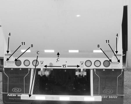
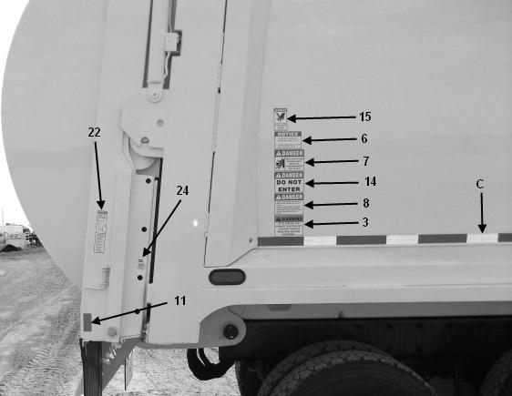
5 SECTION ONE SAFETY PRECAUTIONS GENERAL The New Way Sidewinder Automated Loaders were designed to work hard and withstand the rigors of daily use. The forces used on the packer to compact refuse are accomplished with hydraulic pressure which is created and then directed through hoses to the packer panel. Extreme care and safety practices need to be used at all times while operating the packer. The owner is responsible to require all employees associated with this unit read this manual thoroughly so that they fully understand all the instructions contained within it. Publication of these safety precautions does not imply and should not be considered an all inclusive list. It is the operator s responsibility to learn and follow the proper operational procedures that are in accordance with all safety codes and requirements including the American National Standards Institute (ANSI) requirements and the Occupational Safety and Health Act (OSHA) regulations. ANSI Z has been released and should be followed. Failure to operate this machine correctly, or failure to heed warnings in the operator manual or on the safety decals, may cause DEATH or DIS- MEMBERMENT to the operator, coworkers or bystanders. SAFETY DECALS Safety decals are very important and should be clearly seen and obeyed at all times. Section 1-8 describes a detailed diagram of where the decals should be displayed. If any of these decals are missing or cannot be clearly read, they must be replaced immediately with the proper decal. New decals can be ordered from New Way by calling (800) WARNING CAUTION DANGER As you read this manual you will see the above graphics appear to alert the operator or mechanic of specific issues concerning a particular operation. Operators and maintenance personnel shall read and comply with the instructions carefully. Compliance and common sense are crucial for the safe operational procedures. Note: will also appear and is followed by information that will clarify or provide emphasis to a certain point in the manual. WARNING denotes hazards or unsafe practices which COULD result in severe personal injury or death. CAUTION denotes hazards or unsafe practices which could result in minor personal injury or property damage. DANGER denotes immediate hazards which WILL result in personal injury or death. 1-1
6 SECTION ONE SAFETY PRECAUTIONS PRIOR TO START UP 1. Scranton Manufacturing Co. Inc. Recommends that at a minimum operators wear steel toed safety shoes, OSHA approved safety glasses, and gloves. The company also recommends that operators do not wear any jewelry on their wrists or hands, or loose fitting clothing that could catch on operating levers or moving components of the packer. 2. Do not operate any machinery while under the influence of drugs or alcohol. 3. Before operating this refuse packer, the person(s) should be properly instructed and trained in the operation of the equipment. He or she must also be familiar with all warning devices, hand signals, and traffic rules. 4. Perform a pre-operation inspection of the unit by walking around it and: *Inspect the chassis in accordance with the chassis manufacturer s guidelines. *Inspect the packer in accordance with our Refuse Packer guidelines listed in Section 2 OPERA TION of this manual. DO NOT START OR OPERATE ANY EQUIPMENT THAT IS MALFUNCTION- ING. *Make sure all obstructions and people are clear. *Inspect all lights, back-up and tailgate ajar alarms. *Check all mounting bolts, cylinder pins, and other fasteners for placement and tightness. *Adjust or replace as necessary with the same grade and size. 5. Any malfunctions should be reported to a supervisor or mechanic. Before walking away from a malfunctioning unit do the following: *Set the parking brakes. *Disengage the PTO. *Turn off the engine. *Remove the ignition key. 6. Any service work completed on the unit should be done with the proper tools and procedures as shown in this service manual. Only authorized personnel should attempt the repair work. Use ONLY proper replacement parts on the unit. 7. If the height of your unit was altered, recheck the overall height and make sure this height plus three inches is noted on the decals. 8. Thoroughly understand the functioning of every operating control. Be aware of the function and location of every instrument, control, gauge, and protective device. 9. Know where to get help in case of an emergency
7 SECTION ONE SAFETY PRECAUTIONS GENERAL OPERATION 1. The operator is responsible for making sure that operation of this unit is in accordance with the instructions contained in this manual and all codes including those of the Occupational Safety and Health Act (OSHA) regulations and the American National Standards Institute (ANSI) standards. 2. Do not operate any equipment without proper instruction and training. NOTE: A good source for training is Coaching the Refuse Truck Driver II from National Solid Wastes Management Association, Washington, D.C. Call (800) for pricing information. 3. Before operating this refuse packer, the operator(s) must be properly instructed and trained to be a qualified operator(s). They must be familiar with all danger, caution and warning decals, warning devices, hand signals, and traffic rules. 4. Know the function and location of all instruments, gauges, protective devices, and controls of the unit. 5. Know where to get help in case of an emergency. 6. Each day, prior to the first cycling of the packer panel, open the side access door and visually inspect the area behind the ejection panel. Also inspect the internal body cavity and hopper for abnormal obstructions, equipment, or personnel. 7. Make sure the back-up warning alarm is working properly. 8. Notify the manufacturer of any malfunction or any other observation that could be unsafe for the operator. The manufacturer s name and address are on the cover of this manual. 9. Refer to chassis manufacturer s manual for safety precautions on the chassis. 10. Any damaged Safety or Operational decals should be replaced immediately. Contact New Way at (800) to order free replacements. (Refer to the diagram on Page 1-8). 11. Before operating the unit, put on proper safety equipment such as protective shoes, glasses, appropriate gloves and a safety vest. Also, turn on appropriate warning lights. 12. Seat (safety) belt must be worn at all times - It s The Law! 13. When starting the unit s engine, use the proper procedure as listed in the chassis manufacturer s instruction manual. 14. Before moving the unit or operating any controls make sure coworkers can be seen and that they are in a safe position. 15. While operating the unit, all access doors and service-opening covers must be latched in place and maintained. 16. Personnel should ride only in the cab. Personnel are prohibited from riding on any specified riding platforms or steps if vehicle speeds will exceed 10 mph or more, or if the vehicle will be travelling further that 2/10 of a mile without stopping. Personnel must never dismount any part of the vehicle when it is in motion. 17. Keep side access door and rear tailgate in closed and latched position. 18. Never operate the equipment with the side access door in the open position. 19. Never push or tow anything with the unit. 20. Before traveling in reverse, make sure the area behind the unit is clear of obstructions and then move the vehicle as 1-3
8 SECTION ONE SAFETY PRECAUTIONS slowly as possible. Do not travel in reverse further than distances allowed by local ordinances. If traveling in reverse further than ten feet use a guide. 21. Stop unit immediately if the warning light for the tailgate ajar system comes on. 22. Before leaving the cab, always set the parking brake. 23. Controls or hoses should never be used as hand holds. 24. Before starting to load the packer, make sure all tailgate locks are properly engaged. 25. If the accelerator system is engaged, do not step on the throttle. 26. Do not place head, body, hands, arms, fingers, or any limbs, etc. into a pinch point or any moving parts.- Death or Dismemberment May Occur. 27. Do not attempt to dislodge any material unless wearing approved safety glasses or a full-face shield. 28. Never use this unit to transport a container from one location to another. 29. Container handling cables or chains should never be used for pulling or towing. 30. Container lids should be closed and latched when not being handled. 31. Set the vehicle parking brake before handling a container. 32. Raise the container slowly and smoothly. 33. Read and obey all container decals issued by the container manufacturer. 34. Read and follow container manufacturer s information on accepted use practices. 35. Do not attempt to lift overloaded containers. 36. Center the container on the attachment 37. All containers should be inspected and repaired if not in a safe, usable condition. 38. Never cross under a raised container. 39. Stand clear when dumping containers. 40. In cold weather, make sure container is not frozen to the ground before attempting to lift it. 41. If debris needs to be cleaned from container, first make sure the container is firmly on the ground, then reach inside with a probe or other tool Do not use hands. Never place any part of the body between the packer body and the container. 42. Make sure there is enough overhead clearance before dumping a container. 43. Place the container on a flat, level surface. 1-4
9 SECTION ONE SAFETY PRECAUTIONS 44. Detach container before moving the vehicle. 45. Do not attempt to unload uphill, into the bank of a hill, or against a pile of garbage. 46. Never walk or stand under the tailgate when in the raised position. 47. Before opening the tailgate, be sure there is sufficient overhead clearance. 48. Before raising or lowering the tailgate, warn others and make sure that they are clear of the area. 49. Never move the unit with the tailgate raised unless it is needed to assist unloading of packer contents. 50. The tailgate should always be raised and lowered slowly. 51. Proper maintenance and service of the equipment is necessary to ensure safe and reliable operation. Follow the maintenance schedule and conduct repairs as needed. 52. The following minimal lockout/tag out procedure must be completed before entering into or under any part of the packer.» Park on level surface.» Engage the emergency/park brake.» Disengage the power take-off, pump controls, accelerator switch and place all control handles on the packer in the centered neutral position.» Turn off the truck ignition. Remove key.» Place the truck keys in pocket.» Attach DO NOT OPERATE tag or cover on steering wheel» Chock the wheels. (Refer to the LOCKOUT/TAG OUT Procedure beginning on page 3-1.) 53. In the event the tailgate must be in the open position during maintenance, securely block tailgate and thoroughly test method of blocking prior to proceeding. Tailgate Safety Props have been pre-mounted at the factory for this purpose, and include an operation decal stating proper use procedures to obtain the required two feet of clearance. 54. All hydraulic pressure and electrical programming settings, including over-speed and accelerator settings, are set at the factory and should not be modified. Modifications to these settings may create safety hazards and/or cause serious damage to the equipment. Any modifications to these settings not authorized by the Customer Service Manager or the Chief Engineer of Scranton Mfg. will void warranties. 55. This manual in its entirety is to be considered a permanent part of the equipment. In the event there is a transfer of ownership the manual should be included or transferred with the equipment. 56. Scranton Manufacturing must be notified of the name and address of the new owner in order to make the new owner aware of any safety or service bulletins issued. Scranton Manufacturing can be reached at (800)
10 SECTION ONE SAFETY PRECAUTIONS PRE-OPERATION INSPECTION CHECK- LIST OK NOT OKAY COMMENTS 1. Placement and readability of decals. 2. No fluid leaks. 3. Mounting hardware in place and fastened tightly. 4. No metal fatigue or cracks in welds. 5. Hydraulic fluid reservoir at recommended level, with cylinders retracted. 6. All operation controls function correctly. 7. All debris removed from under and behind ejection panel, and all areas around packing cylinder. Also, between cab and body. 8. All operating and running lights are functional. 9. Engine warmed up according to manufacturer s instructions. 10. Loader arms and forks operate properly. 11. Lid opens and closes properly. 12. Packing cycle operates properly. 13. Back-up and tailgate ajar alarms are functional. 14. Fully charged Fire Extinguisher is in cab. 15. Problems are reported to authorized personnel. Inspector s Signature: Date of Inspection: 1-6
11 SECTION ONE SAFETY PRECAUTIONS HYDRAULICS 1. Hydraulic fluid flows through at very hot temperatures and can cause burns. To protect yourself from such burns, do not touch cylinders, piping, or hoses. 2. When checking for hydraulic fluid leaks never use the hands since escaping hydraulic fluid can cause injuries. DANGER - High Pressure Injection Of Hydraulic Fluid Through The Skin And Into The Bloodstream May Cause Serious Injury Or Death. FIRE PROTECTION 1. Always have a fire extinguisher available and check it monthly to make sure it is fully charged and operable. 2. Never have an open flame around flammable or combustible materials. 3. Never load smoldering ashes into the packer because they could ignite the refuse. HOUSEKEEPING 1. Keep driving area, as well as steps and handholds, clean and free of debris and grease. 2. Make sure maintenance equipment, etc. is kept away from packer controls so they cannot be accidentally activated. SHUTDOWN 1. Set parking brake. 2. Put all controls in neutral. 3. Disengage PTO. 4. Shut off engine. 5. Shut off accelerator dashboard switch. 6. Shut off all accessory switches; work light, strobe or beacon light. 7. Remove ignition key. 8. Lock vehicle. 1-7


12 SECTION ONE SAFETY PRECAUTIONS 1-8

13 SECTION ONE SAFETY PRECAUTIONS 1-9
14 SECTION ONE SAFETY PRECAUTIONS Decals 1 PART # PART # PART # PART # PART # PART # PART # PART # PART # Red Reflectors 11 PART # Amber Reflectors 12 PART # PART #
15 SECTION ONE SAFETY PRECAUTIONS 9 PART # PART # PART # PART # A PART # Logo B PART # White Reflective Sheeting C PART # Red/White Reflective Sheeting D PART # Serial Number Riveted Safety Precautions Decals 1-11


16 17 PART # PART # PART # PART # PART # PART # PART # PART # PART #


17 Mounting Stickers PART # PART # PART #
. 2. Start engine. 3.")
18 SECTION TWO OPERATION THE SIDEWINDER AUTOMATED LOADER HAS BEEN CREATED TO SAFELY AND EFICIENTLY LOAD, COMPACT, TRANSPORT, AND UNLOAD REFUSE. THE FOLLOWING TEXT AND GRAPHICS DESCRIBES HOW TO ACCOMPLISH THOSE TASKS. START-UP INSTRUCTIONS & CHECK-OFF 1. Close air bleeders(usually found on the battery housing). 2. Start engine. 3. Do pre-trip inspection. 4. Check hydraulic reservoir oil level. HYDRAULIC OIL GAGE SECONDARY CONTROL PANEL 2-1


19 SECTION TWO OPERATION PRIMARY CONTROL PANELS 2-2


20 SECTION TWO OPERATION X DECREASING HORIZONTAL IN A PORT CYLIDER RETRACT Y Y INCREASING VERTICAL LIFT DOWN A PORT CYLINDER RETRACT X Y DECREASING VERTICAL LIFT UP B PORT CYLINDER EXTEND Y X X INCREASING HORIZONTAL OUT B PORT CYLINDER EXTEND 4. Upon arriving at the pickup point ensure that both E-Stop buttons on the primary control box are pulled up. 5. Engage the pump. 6. Engage the auto pack. REQUIREMENTS FOR PACKER TO FUNCTION *The packer body needs to be in the full down position. *The tailgate needs to be in the closed and locked position. *The access door needs to be closed and latched shut. *The crusher panel should be in the open position. *For the arm to function the dead man switch on the joy stick must be activated. (if out side the unit and using the secondary control the interlock switch must be activated.) *The arm will only raise half way until the arm is fully retracted. *The grippers will not open after going past the halfway point unless the gripper override is depressed. *When operating in the auto pack mode the retract prox must be seen. If not seen a timer will expire and the packer panel will retract automatically. This sequence will occur 5 consecutive times and then the packer panel will remain in the home position until reset by turning auto pack off and then back on again. (this occurance usually happens when the packer is full.) *The arm is cushioned (slows down) for the up/down or retract cycles. 2-3


21 SECTION TWO OPERATION Grasp Container BEFORE OPERATING THE ARM ENSURE OVERHEAD CLEARANCE The dead man switch on the joy stick will need to be engaged before any function of the Raise arm will work. Extend the arm with the grippers open until the container is reached. Grasp the container with the grippers Retract Arm and raise the container from the ground. (in cold weather ensure container is not frozen down) The arm will need to be fully retracted and then raised to the dumping position as shown. Container Dump Once the container has been dumped reverse the procedure to bring container back to the postition when first grasped. Open the grippers and return the arm to the stowed position. Stowed Position 2-4

22 SECTION TWO OPERATION UNLOADING PROCEDURE ENSURE ENOUGH OVERHEAD CLEARANCE BEFORE ATTEMPTING TO UNLOAD. DO NOT UNLOAD ON A SIDEHILL AND DO NOT DRIVE WITH BODY RAISED OTHER THAN TO FACILITATE UNLOADING. DO NOT UNLOAD AGAINST A PILE OF REFUSE. 2-5

23 SECTION TWO OPERATION UNLOADING PROCEDURE continued 1. Raise tail gate to full open position. 2. Raise body hoist to fully raised postion. 3. Pull ahead VERY SLOWLY to help the load discharge. 4. When load is completely unloaded pull far enough ahead for the unit to clear the pile of refuse. 5. Lower body completely to the down position. 6. Lower tail gate to full closed position and ensure the locks are engaged. REQUIREMENTS FOR UNLOADING THE PACKER *The interlock switch on the secondary control must be engaged to raise the tail gate or the body lift. *The tail gate needs to be full open before raising the body to the full up position. *The tail gate needs to be full open or full closed for the packer panel to move. *The arm must be fully retracted to the stow position before that body will raise. *The packer panel must be in the home position for the tailgate to close. 2-6


24 SECTION TWO OPERATION PROXIMITY SWITCHES AND ARM STOWED SWITCH Hopper Access Door Safety Switch Body Ajar Switch Arm Stowed Switch Crusher Panel Switch Packer Panel Retract & Home Proximity Switches Up Cushion Switch Tail Gate Ajar Switch Gripper Auto Close Switch Down Cushion Switch Arm Cover Removed Horizontal In Cushion Switch 2-7


 boxes.")
25 SECTION TWO OPERATION Clean-Up 1. After driving to safe place, lower tailgate to gain access to tailgate props located on both sides of tailgate. Follow instructions on Decal for Proper Use. Rest Tailgate on Tailgate Safety Props. 2. Remove the ignition key and clean the area to the rear of the packer panel. Do not use your hands. Use a suitable tool such as a wooden handled garden hoe. Clean around the tailgate seal. Do not stand under an open tailgate unless tailgate props are properly in place and tested for steadfastness. NOTE: Keep the ignition key in your pocket for safety purposes. 3. Pull Safety Latch to allow opening of Clean-out Trough Doors on right and left sides. Do not use your hands. Use a suitable tool such as a wooden handled garden hoe. NOTE: When Power-Washing the unit, follow prescribed safety above. Do not direct high pressure wash onto the gray electrical component (enclosure) boxes. Doing so may result in shorting of components. Cleanout Door Shown Closed 4. Close the tailgate, ensure crusher panel is full open and retract packer panel. You are now ready to load more refuse or stow the truck. Cleanout Door Shown Open 2-8
26 SECTION THREE MAINTENANCE WARNING Proper repair and servicing is important to keep your packer operating at peak efficiency. Following are effective methods for performing these procedures. Some of these procedures require special tools. Using improper tools can be dangerous to the person using them. Any modifications to equipment must be done in accordance with American National Standards Institute Z Deviating from these standards could cause damage to the user and operators. Components that exceed 4000 pounds in weight are; Body Shell. Safety Precautions to be taken before performing any service or repair; Do not work inside, underneath, or on top of a truck body without complying with the following precautionary steps. 1. Shut Off Engine. 2. Set Park Brake or Emergency Brake. 3. Place Chocks in front and rear of at least two tires. 4. Remove Ignition Key. Keep key with you at all times. LOCK OUT-TAG OUT PROCEDURE Lock Out Procedure! (To Render Safe And Isolate All Energy Sources.) Always wear safety glasses. A. Hydraulic Disengagement procedures: NOTE: Power take-off: 1. Front Mounted Pump with Electric Controls- With engine at idle, turn pump switch off. Do Not Re-Start Engine as primary pump system would re-engage causing hydraulic flow. Remove ignition keys and place in pocket! 2. Automatic Transmission with Electric Shift PTO - With ignition switch to On, and engine off or at idle, push dash control rocker switch to off position. PTO will disengage. Remove ignition keys and place in pocket! B. Shut down all power sources. 1. Turn off the truck engine, and remove the ignition keys and push down Emergency Stop button. 2. Turn off any auxiliary engines, and remove the ignition keys. 3. Turn off the electric engine, and turn off the power panel. 4. Pull the 30AMP fuse by the battery or kill switch (on the 10AWG RED line). Lock out the power panel and main breaker. Remove keys! ALL KEYS MUST BE PLACED IN YOUR POCKET! NO OTHER KEYS SHOULD BE AVAILABLE TO ANY OTHER PERSONNEL! 3-1
27 SECTION THREE MAINTENANCE LOCK OUT-TAG OUT PROCEDURE (continued) C. Install Tag on steering wheel with non reusable fastener. Example of a Lockout Tag: DANGER EQUIPMENT LOCKED OUT BY: NAME: DEPARTMENT: DATE: TIME: D. Place Equipment in a NON-Freefall Positions. Raised tailgates should be lowered, either under power or by gravity. To achieve this, operate the appropriate tailgate control in a correct manner. E. Raised tailgates may be blocked in raised position by first securing wheels on the road surface with wheel chocks, front and rear, on at least two wheels. This is to prevent truck movement. Whenever possible, use the installed tailgate props that are installed on the tailgate by following the operation decal. When this is not possible, safely block up any tailgate, movable assembly or part, with carefully stacked and nailed 4 x 4 lumber or 6 x 6 lumber. Check the blocking for steadfastness. Carefully lower the weight of the tailgate onto the beams. Test the chocks and tailgate props, or the beams for steadfastness before placing yourself in a potentially dangerous situation. F. Relieving stored hydraulic pressure in all cylinders only when hydraulic maintenance is to be performed. 1. All telescoping hydraulic cylinders used only in conjunction with a packing panel and or ejection panel. a. Secure vehicle to road surface with wheel chocks placed front and rear on at least two wheels. b. Check air tank reserve. Ensure full system pressure air. c. Open all hydraulic shutoff valves incorporated into your particular unit. d. With lockout-tag out in process, turn ignition switch to on. Do Not Start Engine. e. Pull up the Emergency Stop button. Push PTO Reset Button. Operate the manual packer toggle-switch in both forward and reverse direction and hold momentarily in both positions. f. Remove ignition key and close all hydraulic shutoff valves incorporated into your particular unit. g. Loosen the hydraulic fittings to the hydraulic telescoping cylinder at a point of attachment away from the cylinder to be worked upon. Check for any leakage of fluid under residual pressure. h. After residual pressure has been relieved, tighten the previously loosened fittings. i. You have now relieved the stored hydraulic pressure inside of the cylinders to be worked on! You may now proceed as normal unless power is reapplied to the hydraulic system. If power is reapplied, the entire process will need to be repeated. 3-2
28 SECTION THREE MAINTENANCE LOCK OUT-TAG OUT PROCEDURE(continued) 2. Double acting single stage cylinders which hold close a tailgate. NOTE: These cylinders incorporate a SAFETY PILOT CHECK VALVE located underneath the body at the rear. NOTE: The tube side port on these cylinders is always under high pressure! a. Secure vehicle to road surface with wheel chocks placed front and rear on at least two wheels. Test wheel chocks for steadfastness. b. Lower the tailgate if at all possible, by operating the appropriate controls. c. If tailgate cannot be lowered, safely block up with carefully stacked and nailed 4 x 4 lumber or 6 x 6 lumber. Check the blocking for steadfastness. d. After tailgate is lowered or securely supported, perform the following steps. e. Check air tank reserve. Ensure full system air pressure. f. Open all hydraulic shutoff valves incorporated into your particular unit. g. With lockout-tag out in process, turn Ignition Switch to ON. Do Not Start Engine. h. Push the PTO Reset Button In. i. Emergency Stop Button should be in the up position. j. Operate the Tailgate Toggle-Switch in both Up and Down direction and hold momentarily in both positions. k. Remove ignition key and close all hydraulic shutoff valves incorporated into your particular unit. DANGER l. Loosen slowly and carefully the port fitting on the tube side of the cylinder or cylinders to be worked on. Watch out for leakage of fluid under residual high pressure. All shut off valves incorporated in your unit will need closed. m. After residual pressure is removed from hose lines, tighten the loosened fittings. n. You have now relieved the stored hydraulic pressure inside of the cylinders to be worked on! You may now proceed as normal unless power is reapplied to hydraulic system. If power is reapplied, the entire process will have to be repeated. 3. Double acting single stage cylinders which support a load or are used in conjunction with arms or forks: a. Open all shut off valves incorporated into your particular unit s hydraulic system. b. Operate the particular valve control lever for the appropriate cylinder. Operate in both directions and hold the positions momentarily to relieve pressure. 3-3
29 SECTION THREE MAINTENANCE LOCK OUT-TAG OUT PROCEDURES(continued) c. Secure the vehicle to the road surface with wheel chocks placed in front and behind at least two wheels. Test the wheel chocks for steadfastness. d. Safely block up any movable assembly with carefully stacked and nailed 4 x 4 lumber or 6 x 6 lumber. Check the blocking for steadfastness. e. Close all shutoff valves incorporated into your unit. f. Loosen the hydraulic fittings to this cylinder or cylinders at a point of attachment away from the cylinder to be worked on. Check for leakage of fluid under residual pressure. g. After residual pressure is removed from the hose lines, tighten the loosened fittings. Proceed to work as normal on the cylinder or cylinders. ROUTINE WASHING The washing of the interior of the packer body requires Lock Out-Tag Out procedures to be followed. It is strongly suggested that an observer be staioned on the outside of the unit should help be needed. CAUTION The interior of the unit will be very slippery and could become hazardous to the person inside. It is suggested that at a minimum, safety gear should include a rainsuit, goggles, leather gloves and rubber boots. 3-4

30 SECTION THREE MAINTENANCE HOSE # FUNCTION 1 HORIZONTAL RETRACT 2 HORIZONTAL EXTEND 3 VERTICAL RETRACT 4 VERTICAL EXTEND 5 GRIPPER RETRACT 6 GRIPPER EXTEND ARM VALVE HOSE # FUNCTION 1 GRIPPER EXTEND 2 GRIPPER RETRACT 3 VERTICAL EXTEND 4 VERTICAL RERACT 5 HORIZONTAL EXTEND 6 HORIZONTAL RETRACT ARMS HOSE MANIFOLD 3-5

31 SECTION THREE MAINTENANCE BODY VALVE FRONT MOUNT PUMP 3-6
32 SECTION THREE MAINTENANCE B0DY PUMP AND VALVE ADJUSTMENT WARNING Only trained personnel should conduct adjustments to the hydraulic system pressures. Hydraulic pressures set above the stated settings may cause damage to the equipment and/or personal injury. 1.0 PREPERATION (NOTE: ENSURE THAT ALL SAFETY PRECAUTIONS ARE OBSERVED DUR- ING THE PROCEDURE INCLUDING LOCK-OUT /TAG-OUT OF EQUIPMENT) 1.1 Tools required to perform this procedure Large flat tip screwdriver /16 end wrench /64 allen wrench /16 end wrench /2 end wrench 1.2 Preform all start up inspections 2.0 ADJUSTMENT PROCEDURE (NOTE: TAILGATE AND PACKER PANEL PRESSURE ARE CON- TROLLED BY THE SYTEM PRESSURE OF 2450PSI) 2.1 Set pump pressure Extend and hold the packer panel in the extend position Using the 7/16 wrench loosen the lock nut on the pump body relief Using the 9/64 allen wrench adjust the pump body pressure to 2600 PSI (clockwise to increase and counter clockwise to decrease) Tighten the jam nut while holding the adjustment screw at the proper setting 2.2 Body valve pressure adjustment With the packer panel still being held in the extend position Using the 1 1/2 inch wrench loosen the lock nut on the body valve relief Using the large flat tip screwdriver adjust the body valve relief pressure to 2450 PSI (clockwise to increase and counter clockwise to decrease) Tighten the jam nut while holding the adjustment screw at proper setting 2.3 Body lift relief adjustment Raise the body to the full up dump position and hold in dump position Using the 15/16 wrench loosen the lock nut on the body lift relief Using the large flat tip screwdriver adjust the body lift relief pressure to 1500 PSI (clockwise to increase and counter clockwise to decrease) Tighten the jam nut while holding the adjustment screw at proper setting 3-7
33 SECTION THREE MAINTENANCE 2.4 Crusher panel relief adjustment Extend the crusher panel and hold in extended postition Using the 15/16 wrench loosen the lock nut on the crusher panel relief Using the large flat tip screwdriver adjust the crusher panel relief pressure to 1500 PSI (clockwise to increase and counter clockwise to decrease) Tighten the jam nut while holding the adjustment screw at proper setting WARNING ARM PUMP AND VALVE ADJUSTMENT Only trained personnel should conduct adjustments to the hydraulic system pressures. Hydraulic pressures set above the stated settings may cause damage to the equipment and/or personal injury. DANGER EXTREME CAUTION MUST BE USED WHEN USING THE MANUAL OVERRIDE TO ADJUST PRES- SURE SETTINGS ON THE ARM VALVE. STAY CLEAR OF ALL ARM MOVEMENTS. PERSONAL INJURY OR DEATH MAY RESULT FROM PINCH POINTS AND FAST MOVEMENTS OF THE ARM ASSEMBLY. HOSE # FUNCTION 1 HORIZONTAL RETRACT 2 HORIZONTAL EXTEND 3 VERTICAL RETRACT 4 VERTICAL EXTEND 5 GRIPPER RETRACT 6 GRIPPER EXTEND ARM VALVE LOCATION 3-8

34 SECTION THREE MAINTENANCE Front Mount Pump Arm Valve Shown Before Assembly For Clarity 3-9
35 SECTION THREE MAINTENANCE ARM PUMP AND VALVE ADJUSTMENT Cont. 1.0 PREPERATION (NOTE: ENSURE THAT ALL SAFETY PRECAUTIONS ARE OBSERVED DURING THE PROCEDURE INCLUDING LOCK-OUT /TAG-OUT OF EQUIPMENT) 1.1 Tools required to perform this procedure /64 allen wrench /16 end wrench /32 allen wrench mm end wrench mm allen wrench 1.2 Preform all start up inspections 1.3 Turn adjustment for arm valve pressure clockwise 1 turn from factory setting using the 5/32 allen wrench. This will allow pump pressure to be set. 2.0 ADJUSTMENT PROCEDURE (NOTE: HORIZONTAL PRESSURE IS CONTROLLED BY THE SYTEM PRESSURE OF 2000PSI) 2.1 Set pump pressure Extend and hold the arm in the extend position Using the 7/16 wrench loosen the lock nut on the arm pump relief Using the 9/64 allen wrench adjust the arm pump pressure to 2150 PSI (clockwise to increase and counter clockwise to decrease) Tighten the jam nut while holding the adjustment screw at the proper setting 2.2 Arm valve pressure adjustment With the arm still being held in the extend position Using the 5/32 allen wrench adjust the main valve pressure to 2000 PSI (clockwise to increase and counter clockwise to decrease) 3-10
36 SECTION THREE MAINTENANCE 2.3 Vertical function adjustment With the gripper head held in the extend position or up position Using the 5/32 allen wrench set the extend pressure to 1500 PSI (clockwise to increase and counter clockwise to decrease) With the gripper head held in the retract position or down position Using the 5/32 allen wrench set the retract pressure to 1500 PSI 2.4 Gripper valve pressure adjustment (clockwise to increase and counter clockwise to decrease) With the gripper held in the open (retract) position Using the 5/32 allen wrench set the retract to 1900 PSI (clockwise to increase and counter clockwise to decrease) With the gripper held in the closed (extend) position Using the 5/32 allen wrench set the extend pressure to 675 PSI (clockwise to increase and counter clockwise to decrease) 3.0 NOTE: ALTHOUGH FACTORY SETTINGS ARE RECOMMENDED THE SPEED OF THE GRIPPERS CAN BE CHANGED BY USING THE 10mm WRENCH TO LOOSEN THE NUT ON THE LIMIT ADJUST- ING SCREW AND USING THE 3mm ALLEN WRENCH TO ADJUST THE SPEED. (clockwise to slow down and counterclockwise to speed up) 3-11
37 SECTION THREE MAINTENANCE ARM BOLT TORQUE SPECIFICATIONS 3-12

38 SECTION THREE MAINTENANCE CRITICAL ADJUSTMENT OF ARM CHAIN FIG 1 Shows the arm chains out of adjustment. A visual inspection of the lift arms should be done daily as this is a critical adjustment. Failure to keep these chains properly adjusted will cause excessive wear on the lift arms and improper functioning of the arm and grabber. 3-13
 FIG 2 3.")
39 SECTION THREE MAINTENANCE ADJUSTMENT OF ARM CHAIN PROCEDURE Initiate Lockout/Tagout Procedures. 1.0 Retract (lower) the vertical cylinder (arm raise or lower) completely. 2.0 Loosen the two top chain adjustment nuts one turn.(see FIG 2 for location) FIG Adjust the gripper head IN or OUT using the bottom adjustment nuts until the gripper head is flush with the front vertical support plate. (see FIG 2 for lower chain adjustment nuts)(see FIG 3 for proper alignment) FIG

40 SECTION THREE MAINTENANCE FIG 4 FIG 4 shows the lift arm when adjustment is correct. 4.0 When both conditions shown in FIG 3 and FIG 4 have been met torque upper adjusting nuts to 40 ft lbs 3-15

41 SECTION THREE MAINTENANCE SIDEWINDER DAILY MAINTENANCE 1. Lockout-Tag Out procedures should be followed. 2. Inspect all safety and operational decals. Ensure that all are ledgible and intact. If replacements are neccesary, contact your local New Way distributor or call the factory for replacement decals. 3. Inspect all lights and ensure they are functioning properly. 4. Ensure that the back up alarm and tailgate ajar alarm are working properly. 5. Inspect the chassis in accordance with the chassis manufacturer s guide lines. 6. Check the hydraulic tank sight gauge with the engine off and the manual shut off in the open position to ensure recommended oil level. 7. Inspect all hoses and fittings for leakage. Repair or replace as neccesary. 8. Inspect all mounting bolts, cylinder pins and other fasteners for placement and tightness. Adjust and replace as neccesary using the same grade and size fasteners. 9. Inspect all cylinder mounting points for metal fatigue or cracked welds. 10. Ensure all switches, control levers and buttons are functioning correctly. 11. Using the wooden handled garden hoe provided (replace if neccesary), remove all debris from under and behind ejection panel and the area around the telescoping ejection cylinders. FRONT MOUNT PUMPS Front mount pump drive shafts should be inspected daily for tightness of the set screws where the shaft attaches to the pump. There are four bolts to the engine flywheel to check for tightness also. The three grease fittings should be greased daily. Every six months the set screw should be loosened and the knuckle removed from the splined shaft. New spline lubricant (part #119732) should be applied and the assembly replaced. SLIDE ZERK SET SCREWS (3) BOLTS TO ENGINE (4) KNUCKLE ZERKS 3-16
 can be greased on the street side of the unit.")
 can be greased with the arm in the stowed postition for the street side cylinder ends.")
 The gripper pivot pins can be greased (4 places) with the grippers in the open position.")
42 SECTION THREE MAINTENANCE DAILY LUBRICATION POINTS (LIFT ARM 29 GREASE ZERK LOCATIONS) STREET SIDE LUBE POINTS ON ARM With the arm in the stowed postion, the roller bearing blocks (4 places) can be greased on the street side of the unit. There are also roller bearing blocks (2 places) on the curb side of the unit (not shown) that can be greased when the arm is extended. The two horizontal cylinders (2 places) can be greased with the arm in the stowed postition for the street side cylinder ends. The curb side horizontal cylinder ends can be greased (2 places not shown) when the arm is extended. GRIPPER PIVOT POINT AND CYLINDER LUBE POINTS VERTICAL CYLINDER TOP LUBE POINT (BETWEEN CHAINS) The gripper pivot pins can be greased (4 places) with the grippers in the open position. The gripper cylinders can be greased with the arm slightly extended. (2 places on each end of cylider) VERTICAL CYLINDER BOTTOM LUBE POINTS (2 POINTS) The vertical cylinder located in the center of the arm above the grippers has two places on the bottom of the cylinder and one place on the top between the lift chains. 3-17


 LOWER RAIL ROLLERS LUBE")

43 SECTION THREE MAINTENANCE The arm lift outer mechanism has two places on the bottom of the mechanism and two places on the top as shown. The inner mechanism has the two places as shown on the bottom. There are two rollers on the shaft under the rails that the arm extend ride on. There is one place to grease on each roller ARM LIFT MECHANISM LUBE POINTS (6 POINTS) LOWER RAIL ROLLERS LUBE POINTS (2 POINTS) RIGHT AND LEFT LOWER RAIL ON CURB SIDE PACKER PANEL CYLINDER OUTER CYLINDER HEAD GREASE POINTS(1 POINT EACH CYLINDER) PACKER PANEL CYLINDER INNER CYLINDER HEAD GREASE POINTS (2 POINTS) CURB SIDE STREET SIDE 3-18


 1 CYLINDER ON EACH")
 ONE POINT ON EACH SIDE ON THE BLOCK BASE OF")

44 SECTION THREE MAINTENANCE SIDEWINDER WEEKLY MAINTENANCE Lubricate all friction points that do not have grease zerks, such as the hopper access door and the clean out door hinges with a quality 30 weight oil. The following grease points will need to be greased weekly. TAIL GATE CYLINDERS (2 POINTS) 1 CYLINDER ON EACH SIDE OF THE TAIL GATE TAIL GATE LOCKING MECHANISM (2 POINTS) ONE POINT ON EACH SIDE ON THE BLOCK BASE OF BODY LIFT CYLINDER (5 POINTS) 2 ON EACH SIDE OF CYLYNDER AND 1 IN THE CENTER ON THE COLLAR BODY PIVOT LUBE LOCATIONS STREET SIDE SHOWN (6 POINTS) 3 ON EACH SIDE OF THE PIVOT POINT (CENTER POINT NOT SHOWN) 3-19

 High pressure internal elements Part #111472 (2 required) Breather filter Part #106207 OIL SUPPLY TANK 1.")
45 SECTION THREE MAINTENANCE SIDEWINDER MONTHLY MAINTENANCE 1. Check all wiring connections. Tighten or replace as necessary. 2. Check wires for excessive wear, kinking or crimping. Replace as necessary. 3. Check all fasteners for excessive wear and tightness. Replace or tighten as necessary. 4. Check all hydraulic hoses and pipes for damage and wear. Replace as necessary. 5. Check all air supply lines for rubbing and chafing. Replace as necessary. 6. Check all decals for readability. Replace Damaged Decals (free replacements). See pages 1-8 through 1-14 in Section 1. NOTE: Low pressure spin on filters Part # (2 required) High pressure internal elements Part # (2 required) Breather filter Part # OIL SUPPLY TANK 1. Hydraulic oil filters: Replace after the first 50 hours of use and every 250 hours thereafter. (Note: Hydraulic oil filter should be changed in the case of any major hydraulic component failure.) 2. Air Filter / Breather Cap: It must allow free air flow for the hydraulic oil tank. Inspect daily to assure that the cap is properly attached and free of obstruction. Wash foam prefilter in soapy water, rinse and air dry every 3 months. Replace cartridge element every six months (minimum) and more frequently in dirty conditions. 3. Hydraulic fluid: Replace after first six (6) months and every year thereafter. Refer to oil specifications for replacement oil. (Note: Oil should be drained and replaced in the case of any major hydraulic component failure.) 4. Suction strainer: Remove and clean the screen each time the oil is changed. 5. The optional high pressure filters should be changed at the same interval as the hydraulic oil filter. 3-20
46 SECTION THREE MAINTENANCE OIL SPECIFICATION CHART BRAND NORTHLAND TALAMAR NORTHLAND TALAMAR EXTREME (BLUE IN COLOR) ALL SEASON (RED IN COLOR) IOS Viscosity Grade ASTM D Gravity Def.API ASTM D Specific Gravity ASTM D Pour Point Degree F ASTM D Flash Point Degree F ASTM D Viscosity:cST@40c cst2100c ASTM D Viscosity: SUS@100f SUS@210F ASTM D Viscosity Index: min ASTM D typical Brookfield Viscosity ASTM D cp,max@-20f Rust Test ASTM D665 pass pass Foam Test: max ASTM D892 10/0 10/0 20/0 20/0 10/0 10/0 Dielectric Strength, KV min NOTE: When adding or replacing the hydraulic fluid, give the above information to you supplier to provide a similar product. The oil provided with the unit is a premium hydraulic fluid that is formulated to meet the stringent performance requirements of refuse collection equipment exposed to broad ambient operating temperatures. 3-21
47 SECTION THREE MAINTENANCE 3-22
48 SECTION THREE MAINTENANCE 3-23


49 SECTION THREE MAINTENANCE MAC AIR VALVE DENISON T6DC FRONT MOUNT PUMP PART #
50 SECTION THREE MAINTENANCE 3-25
51 SECTION FOUR ELECTRICAL OVERVIEW OF INTERLOCKS >If the door saftey prox (i16) is not activated the main air supply (Q10) and pump (Q1) will kick out. >Hit momentary PTO reset button (i4) to re-activate the main air supply (Q10) and pump (Q1), door saftey prox (i16) is not triggered, door saftey prox (i16) is de-energized, or key is turned off. >Tailgate can not close (Q7) unless ejection panel is at home prox (i14) position. >Unless tailgate is fully open and mercury switch is activated (i9) ejection panel cannot go past the retract prox (i13). >If the tailgate is not fully closed (i8) or fully open (i9) ejection panel will not extend (Q8). >If the tailgate is not fully closed (i8) the tailgate ajar light (Q3) will flash and the buzzer will go off. >When the crusher panel prox (i10) is tripped, the crusher panel open light (Q4) will activate. >During retract of the Auto-pack cycle, the one-shot (Q4) feature will activate telling the tailgate cylinders to retract (Q7). >If the safety door switch (i16) is deactivated, the main air supply solenoid (Q10) and pump (Q1) power will kick out. The safety door switch (i16) must be activated to allow the main air supply solenoid (Q10) and pump (Q1) to be re-energized. >If autopack on switch (i12) is activated the ejection panel will continue to cycle. There is a 1/2 second delay on the extend and retract to eliminate hydraulic shock. NOTE: If the panel does not reach the retract prox switch within 22 seconds it will automatically retract. It will do this cycle 5 times and then shut down. The autopack switch will need to be turned of and then turned back on to reset. When the auto pack switch is turned off the panel will return to the home position. >If the arm stowed switch (i15) is not activated the body raise (Q13) will not function. >If the body ajar prox (i18) is not activated the body ajar light (Q12) will illuminate. 4-1
52 SECTION FOUR ELECTRICAL 4-2
53 SECTION FOUR ELECTRICAL 1. Revisions LEVEL DESCRIPTION ECO NUMBER DATE BY 104 CREATED 7/10/09 CSS 105 Added two manual switches to allow operator to operate from outside the cab at 50% speed. In/Out and Up/Dwn 3/10/10 CSS 2. Software Specification Module NODE HWD Baud Program Number # Version Rate v K SA Description of Operation Joystick functions X and Y are both controlling PVEA sections. X-Axis -X decreasing -horizontal mast in -controls b-port on valve -cyl retract port -X increasing -horizontal mast out -controls a-port on valve -cyl extend port Y-Axis -Y decreasing -vertical lift up -controls a-port on valve -cyl extend port -Y increasing -vertical lift down -controls b-port on valve -cyl retract port 1.Controller must have input from the deadman switch to activate any of the valve functions. 2. Inputs at pin # s 6 and 7 are the input commands which control the PVEO section. -Input 6 (grip open) controls the A port on the valve. Output disabled if Grip auto close prox is on. 4-3
54 SECTION FOUR ELECTRICAL seen. -Input 7 (grip close) controls the B port on the valve. Output disabled if Disable grip close SW is -If the controller sees grip auto close prox, Grip close (B port on the PVEO section) needs to be activated for a duration of 2sec., Even if it continues to see the input. Timer will be reset once it goes away. 3. If arm in cushion prox is present the output to the B-port on the valve controlled by the X axis (X decreasing) needs to be ramped down to X%(needs to be adjustable from 0-100% of the output commanded). This is to act as a cushion for the horizontal mast in. 4. If Arm up cushion prox is present the output to the A-port on the valve controlled by the Y axis (Y decreasing) needs to be ramped down to X%(needs to be adjustable from 0-100% of the output commanded). This is to act as a cushion for the Vertical lift up. 5. If Arm down cushion prox is present the output to the B-port on the valve controlled by the Y axis (Y increasing) needs to be ramped down to X%(needs to be adjustable from 0-100% of the output commanded). This is to act as a cushion for the Vertical lift down. 6. If Body ajar prox is present Arm up (vertical lift up, a-port on valve) is to be disabled. 7. If Hopper door open prox is NOT present, Arm up (vertical lift up, a-port on valve) is to be disabled. 8. If Gripper auto close prox and NOT Arm in prox (vertical lift up, a-port on valve) is to be disabled to prevent garbage being dumped prematurely. 9. If E-stop is NOT present nothing works. -In order for the system to operate either by flashing power to the controller, or releasing the E-Stop, the controller needs to see a momentary reset button input to resume normal operation. 10. There are ramp and deceleration rates for the X and Y axis outputs. Blink Codes: Blink Code Reason for Fault Corrective Action 21 Sensor power Fault Sensor power shorted to ground or too high. 22 Grip close output Output coil open or short detected, check wiring, or replace coil. 23 Grip open output Output coil open or short detected, check wiring, or replace coil. 24 In/Out Enable coil Output coil open or short detected, check wiring, or replace coil. 25 X-axis out of range Shorted, open circuit or bad joystick. 26 Y-axis out of range Shorted, open circuit or bad joystick. 27 Up/Down Enable Output coil open or short detected, check wiring, or replace coil. 28 X-axis compare Sensors on X axis out of range, replace joystick. 29 Y-axis compare Sensors on Y axis out of range, replace joystick. 4-4
55 SECTION FOUR ELECTRICAL 4-5
56 SECTION FOUR ELECTRICAL 4-6
57 SECTION FOUR ELECTRICAL 4-7
58 SECTION FOUR ELECTRICAL 4-8
59 SECTION FOUR ELECTRICAL 4-9
60 SECTION FOUR ELECTRICAL 4-10
61 SECTION FOUR ELECTRICAL 4-11
62 SECTION FOUR ELECTRICAL 4-12
63 SECTION FOUR ELECTRICAL 4-13
64 SECTION FOUR ELECTRICAL 4-14
65 SECTION FOUR ELECTRICAL 4-15
66 SECTION FOUR ELECTRICAL 4-16
67 SECTION FOUR ELECTRICAL 4-17

68 SECTION FOUR ELECTRICAL 4-18


69 SECTION FIVE TROUBLE SHOOT LED TEST LIGHT DIGITAL MULTI METER 5-1
OPTIMIZER TM OPERATOR MANUAL. Author: Labrie. Release Date: 1/31/07. Part #: 90320
 OPTIMIZER TM OPERATOR MANUAL Author: Labrie Release Date: 1/31/07 Part #: 90320 Table of Contents Introduction Introducing the Optimizer TM... 1 Product Overview... 1 Contacting Labrie Environmental Group...
DuraPack Python AUTOMATED SIDE LOADER. Operator s Manual. 2005, The Heil Co. #MR
 DuraPack Python AUTOMATED SIDE LOADER Operator s Manual 2005, The Heil Co. #MR-74958-105 SECTION 1 - GENERAL Introduction... 1.2 Warranty Claims/Inquiries... 1.2 Service/Parts Assistance... 1.3 Directional
Owner s/operator s Manual
 DRIVING THE DIFFERENCE Owner s/operator s Manual MAMBA HB SERIES SCRANTON MANUFACTURING CO, INC. 101 STATE ST, PO BOX 336 SCRANTON, IOWA 51462 (712) 652-3396 OR (800) 831-1858 FAX (712) 652-3399 www.drivingthedifference.com
1500 Series Roll Off Hoist. Owner s Manual (5-06)
") 1500 Series Roll Off Hoist Owner s Manual (5-06) Section 1: General Information Introduction Safety Information Warranty Information Table of Contents Section 2: Operation Operating the P.T.O. Operating
1500 Series Roll Off Hoist Owner s Manual (5-06) Section 1: General Information Introduction Safety Information Warranty Information Table of Contents Section 2: Operation Operating the P.T.O. Operating
Durapack Python Automated Side Loader (Heil Garbage Truck 2006 Units)
") Durapack Python Automated Side Loader (Heil Garbage Truck 2006 Units) Maintenance and Adjustment Safety Messages During repairs to the tailgate, packing mechanism, or hydraulic drive system, a lockout
Durapack Python Automated Side Loader (Heil Garbage Truck 2006 Units) Maintenance and Adjustment Safety Messages During repairs to the tailgate, packing mechanism, or hydraulic drive system, a lockout
Property of American Airlines
 Section 2: Operation 1. GENERAL INFORMATION Safety First! is the motto at Tesco; therefore, the first part of the Operation section begins with safety features and procedures. Operation of the Tesco CL80-20
CAUTION. Start & Stop Procedures. Section 1-2. Engine Oil Level
 Section 1-2 Start & Stop Procedures Before operating this machine, the operator must have: received operator training, a familiarity with this manual, and a complete understanding of all the procedures
610 BUSHEL MANURE SPREADER
 610 BUSHEL MANURE SPREADER RODA MANUFACTURING 1008 LOCUST ST. HULL, IA. 51239 Art s-way Manufacturing 712-439-2366 Co., Inc. Hwy 9 West - PO Box 288 WWW.RODAMFG.COM Armstrong, IA. 50514 U.S.A 2 INTRODUCTION
PowerLevel s e r i e s
 Owner s Manual Hydraulic Leveling CONTENTS Introduction Operation Control Panel Automatic Leveling Manual Leveling Retracting Jacks Remote Operation Care & Maintenance Troubleshooting Error Codes 1 2 2
1250 LB. CAPACITY MECHANICAL WHEEL DOLLY
 1250 LB. CAPACITY MECHANICAL WHEEL DOLLY 67287 SET-UP AND OPERATING INSTRUCTIONS Visit our website at: http://www.harborfreight.com Read this material before using this product. Failure to do so can result
MK AUGERS POWER SWING KIT ASSEMBLY & OPERATION MANUAL
 MK AUGERS POWER SWING KIT ASSEMBLY & OPERATION MANUAL Read this manual before using product. Failure to follow instructions and safety precautions can result in serious injury, death, or property damage.
4400-Lb. Capacity Pallet Jack
 Read carefully and understand all ASSEMBLY AND OPERATION INSTRUCTIONS before operating. Failure to follow the safety rules and other basic safety precautions may result in serious personal injury. Item#
HYDRAULIC LEVELING SYSTEMS OPERATIONS MANUAL (For systems with touch pad part number , , , , or no number at all)
") HYDRAULIC LEVELING SYSTEMS OPERATIONS MANUAL (For systems with touch pad part number 500089, 500105, 500210, 500456, 500535 or no number at all) Visit us on the web at www.powergearus.com 82-L0040-01 Rev.
HYDRAULIC LEVELING SYSTEMS OPERATIONS MANUAL (For systems with touch pad part number 500089, 500105, 500210, 500456, 500535 or no number at all) Visit us on the web at www.powergearus.com 82-L0040-01 Rev.
Hydraulic Immediate Need Power Pack
 Safety, Operation, and Maintenance Manual WARNING Improper use of this tool can result in serious bodily injury This manual contains important information about product function and safety. Please read
Operating Instructions & Parts Manual
 Swift Lift Hydraulic Service Jack Operating Instructions & Parts Manual Model Number ATD7341 Capacity 3-1/2 Ton U.S. Patent No's. 5,946,912 6,199,379! This is the safety alert symbol. It is used to alert
3-Pt. Quick Hitch. Owner s Manual
 3-Pt. Quick Hitch Owner s Manual WARNING: Read carefully and understand all ASSEMBLY AND OPERATION INSTRUCTIONS before operating. Failure to follow the safety rules and other basic safety precautions may
Hydraulic PTO Flow Device
 Safety, Operation, and Maintenance Manual WARNING Improper use of this tool can result in serious bodily injury This manual contains important information about product function and safety. Please read
before serial number 2214
 before serial number 2214 Contents Page Safety Rules... 3 Pre-operational & Safety Inspection... 4 Operating Instructions... 6 Transport... 12 Maintenance & Routine Service... 12 Specifications... 14 SAFETY
CAUTION. Start & Stop Procedures. Section 4-2. Engine Oil Level
 Section 4-2 Start & Stop Procedures Before operating this machine, the operator must have: received operator training, a familiarity with this manual, and a complete understanding of all the procedures
I. INSTALLATION INSTRUCTIONS
 I. INSTALLATION INSTRUCTIONS IT SHALL BE THE RESPONSIBILITY OF THE INSTALLER OF SELF--CONTAINED COMPACTORS TO INSTALL SELF--CONTAINED COMPACTORS IN ACCORDANCE WITH APPLICABLE CODES, LOCAL ORDINANCES, AND
Warranty Information Operators Manual Installation Instructions. Sudenga
 Warranty Information Operators Manual Installation Instructions Sudenga Rust Sales, Inc. 2964 164 th Ave SE Harwood, ND 58042 (800) 478-7801 (701) 282-9194 www.hopperwalker.com Limited Warranty Statement
WALKIE HIGH LIFT HYDRAULIC SYSTEM
 WALKIE HIGH LIFT HYDRAULIC SYSTEM W30-40ZA [B453]; W20-30ZR [B455]; W25-30-40ZC [B454] PART NO. 1524251 2000 SRM 1025 SAFETY PRECAUTIONS MAINTENANCE AND REPAIR When lifting parts or assemblies, make sure
Long Chassis Hydraulic Service Jacks
 Model BH6011 Long Chassis Hydraulic Service Jacks Operating Instructions and Parts Manual Capacity 10 Ton Model BH6011 U.S. Patent No's. 5,946,912 5,341,723! This is the safety alert symbol. It is used
Model 289F. Operator s Manual for Morse Model 289F. MORStak TM Forklift-Mounted Drum Racker. The Specialist In Drum Handling Equipment
 Contents Page Receiving Procedures.................... 1 Warranty............................. 1 Safety Information..................... 1-2 Machine Description................... 3 Operating Instructions....................
ROTARY BRUSH CUTTERS THE LEADER OF THE PACK OWNER/OPERATOR SAFETY & INSTRUCTION MANUAL
 72 M-AX ROTARY BRUSH CUTTERS THE LEADER OF THE PACK OWNER/OPERATOR SAFETY & INSTRUCTION MANUAL CONTENTS Page 1. Introduction..................................2 2. Safety Instructions...........................3-4
HINO PTO INTERFACE PTO INSTALLATION AND OPERATOR S MANUAL KEEP IN VEHICLE. FOR Allison 2500 With CS6B-A67**-S3*H PTO
 KEEP IN VEHICLE READ OPERATING INSTRUCTIONS INSIDE BEFORE OPERATING PTO HINO PTO INTERFACE PTO INSTALLATION AND OPERATOR S MANUAL FOR Allison 2500 With CS6B-A67**-S3*H PTO Muncie Power Products, Inc. Important
1000-lb Hydraulic Truck Crane
 1000-lb Hydraulic Truck Crane Owner s Manual WARNING: Read carefully and understand all ASSEMBLY AND OPERATION INSTRUCTIONS before operating. Failure to follow the safety rules and other basic safety precautions
Instruction Manual 30K - Fifth Wheel Hitch Part Number 30054
 You can take it with you. ELKHART, IN., OAKVILLE, ONT. Instruction Manual 30K - Fifth Wheel Hitch Part Number 30054 DEALER/INSTALLER: (1) Provide this Manual to end user. (2) Physically demonstrate hitching
Wind and Temperature Tip Over Hazard Do not add notice boards or similar
 Lift & Work Platform Safety Information Safety Information: Boom Lifts Safety Information: Scissor Lifts Safety Information: Boom Lifts Power Lines Electrocution Hazard Maintain safe clearance from Electrical
TT-12 OWNERS MANUAL/PARTS LIST
 TOPLIFTER Tailgates By THIEMAN TT-12 OWNERS MANUAL/PARTS LIST SHOWN WITH OPTIONAL 2 PC. ALUMINUM PLATFORM! IMPORTANT! KEEP IN VEHICLE! PLEASE READ AND UNDERSTAND THE CONTENTS OF THIS MANUAL BEFORE OPERATING
2000-LB. ENGINE STAND
 2000-LB. ENGINE STAND WARNING: Read carefully and understand all ASSEMBLY AND OPERATION INSTRUCTIONS before operating. Failure to follow the safety rules and other basic safety precautions may result in
Before equipment use, please read this operation manual carefully. Serial Number: Date Purchased:
 Pushed & Geared Trolleys OPERATION MANUAL This operation manual is intended as an instruction manual for trained personnel who are in charge of installation, maintenance, repair etc. Before equipment use,
EASY DUMP RD3100 / RD3106 (Standard)-(60/40 Split)-(60/40 Divider)- (70/30 Split with Bayne) USER S MANUAL
-(60/40 Split)-(60/40 Divider)- (70/30 Split with Bayne) USER S MANUAL") EASY DUMP RD3100 / RD3106 (Standard)-(60/40 Split)-(60/40 Divider)- (70/30 Split with Bayne) USER S MANUAL *** Important *** Read User s Manual Completely Prior to Operating Par-Kan Company Phone: 1-800-291-5487
EASY DUMP RD3100 / RD3106 (Standard)-(60/40 Split)-(60/40 Divider)- (70/30 Split with Bayne) USER S MANUAL *** Important *** Read User s Manual Completely Prior to Operating Par-Kan Company Phone: 1-800-291-5487
1000-LB. MOTORCYCLE LIFT TABLE OWNER S MANUAL
 1000-LB. MOTORCYCLE LIFT TABLE OWNER S MANUAL WARNING: Read carefully and understand all ASSEMBLY AND OPERATION INSTRUCTIONS before operating. Failure to follow the safety rules and other basic safety
Low Profile Service Jack
 Low Profile Service Jack Model GMG29031 Capacity 3 Ton U.S. Patent No. 6,199,379! This is the safety alert symbol. It is used to alert you to potential personal injury hazards. Obey all safety messages
Trench Filler for Compact Utility Loaders
 Form No. 3353-608 Rev A Trench Filler for Compact Utility Loaders Model No. 22472 260000001 and Up Operator s Manual Register your product at www.toro.com Original Instructions (EN) Contents Page Introduction................................
Low Profile Service Jack Jack Stand Combo
 Low Profile Service Jack Jack Stand Combo Jack Stands Low Profile Service Jack U.S. Patent No. 6,199,379! This is the safety alert symbol. It is used to alert you to potential personal injury hazards.
Heavy-Duty Drywall Dolly Cart
 Heavy-Duty Drywall Dolly Cart Owner s Manual WARNING: Read carefully and understand all ASSEMBLY AND OPERATION INSTRUCTIONS before operating. Failure to follow the safety rules and other basic safety precautions
Operating Instructions - Electric Pow'r-Riser Models
 ADivisionOf Templeton, Kenly& Co., Inc. Operating Instructions - Electric Pow'r-Riser Models Table of Contents 1.0 Recieving Instructions 2.0 Safety 3.0 Specifications 4.0 Initial Installation Before Operating
PNEUMATIC SLIDING VALVE
 INSTALLATION, OPERATION, & #: MM-SV001 6-23-09 Rev. A Page 1 of 8 PNEUMATIC SLIDING VALVE PART NUMBERS (Including, but not inclusive) SV704MSTS, SV714MSTS, SV754MSTS, SV764MSTS, SV774MSTS, SV706MSTS, SV716MSTS,
HURRICANE 300 INSPECTION/MAINTENANCE MANUAL. N7959 BIRCH ROAD IXONIA, WI FAX:
 HURRICANE 300 INSPECTION/MAINTENANCE MANUAL N7959 BIRCH ROAD IXONIA, WI 53036 www.industrialvacuum.com 800-331-4832 FAX: 920-261-11 OPERATION / MAINTENANCE MANUAL HURRICANE 300 INTRODUCTION The Hurricane
150-Lb. Drywall and Panel Hoist
 150-Lb. Drywall and Panel Hoist Owner s Manual WARNING: Read carefully and understand all ASSEMBLY AND OPERATION INSTRUCTIONS before operating. Failure to follow the safety rules and other basic safety
Fast Lift Service Jack, Low Profile
 Blackhawk Automotive is a Licensed Trade Mark Made by SFA Companies, Kansas City, MO Fast Lift Service Jack, Low Profile Operating Instructions & Parts Manual Model BH6023B Capacity 2 Ton! U.S. Patent
Large Hydraulic Bead Breaker
 Large Hydraulic Bead Breaker Owner s Manual WARNING: Read carefully and understand all ASSEMBLY AND OPERATION INSTRUCTIONS before operating. Failure to follow the safety rules and other basic safety precautions
Airflo MANUFACTURING CO., INC.
 Airflo MANUFACTURING CO., INC. 365 UPPER OAKWOOD AVE, ELMIRA NY 14903 PHONE: 607-733-8284 / FAX: 607-733-0587 OPERATOR & PARTS MANUAL PSV-8L ELECTRIC SPREADER Visit our website at www.air-flo.com Contents
Westfield, Mayrath, Hutchinson, Wheatheart
 Warranty Information Operators Manual Installation Instructions Westfield, Mayrath, Hutchinson, Wheatheart Rust Sales, Inc. 2964 164 th Ave SE Harwood, ND 58042 (800) 478-7801 (701) 282-9194 www.hopperwalker.com
Air-Operated Waste Oil Drainer
 Air-Operated Waste Oil Drainer 20-Gallon Tank Owner s Manual WARNING: Read carefully and understand all ASSEMBLY AND OPERATION INSTRUCTIONS before operating. Failure to follow the safety rules and other
Hydraulic Bead Breaker Kit
 Hydraulic Bead Breaker Kit Owner s Manual WARNING: Read carefully and understand all ASSEMBLY AND OPERATION INSTRUCTIONS before operating. Failure to follow the safety rules and other basic safety precautions
Operators manual Bumpa 8 metre 110v Bumpa 10 metre 110v
 Operators manual Bumpa 8 metre 110v Bumpa 10 metre 110v SAFETY RULES Mk3 Bumpa Conveyor Danger Failure to obey the instructions and safety rules in this manual will result in death or serious injury. Do
TABLE OF CONTENTS. Warranty Disclaimers Delivery Checklist After Sale Checklist Safety Set Up... 8
 TABLE OF CONTENTS Pickett Equipment Warranty... 2 Warranty Disclaimers... 3 Delivery Checklist... 4 After Sale Checklist... 4 Safety... 5-7 Set Up... 8 Machine Adjustments and Operation... 9 Maintenance
CORPORATION OPERATOR S MANUAL HWH HYDRAULIC SPACEMAKER ROOM EXTENSION SYSTEMS. FEATURING: Single / Multiple Room Extensions / Generator Slide
 HWH CORPORATION R OPERATOR S MANUAL HWH HYDRAULIC SPACEMAKER R ROOM EXTENSION SYSTEMS R FEATURING: Single / Multiple Room Extensions / Generator Slide H W H CORPORATION R HYDRAULIC ROOM EXTENSION OFF EXTEND
Important. Contents. Contact us:
 Operator's Manual First Edition Ninth Printing Important Read, understand and obey these safety rules and operating instructions before operating this machine. Only trained and authorized personnel shall
Important. Contents. Contact us:
 Operator's Manual Third Edition Third Printing Important Read, understand and obey these safety rules and operating instructions before operating this machine. Only trained and authorized personnel shall
MagicLift Hydraulic Service Jack Model (w/one piece handle) (w/one piece handle)
 (w/one piece handle)") Operating Instructions & Parts Manual MagicLift Hydraulic Service Jack Model 27025 27026 (w/one piece handle) 27035 27036 (w/one piece handle) Capacity 2-1/2 Ton 2-1/2 Ton 3-1/2 Ton 3-1/2 Ton Model 27025
Operating Instructions & Parts Manual MagicLift Hydraulic Service Jack Model 27025 27026 (w/one piece handle) 27035 27036 (w/one piece handle) Capacity 2-1/2 Ton 2-1/2 Ton 3-1/2 Ton 3-1/2 Ton Model 27025
Mulcher Operators Manual
 Mulcher Operators Manual Skid Pro Attachments PO Box 982 Alexandria, MN 56308 October 2015 1 2 Contents 1. Introduction And Warranty... 4 1.1 Introduction... 4 1.2 Warranty... 4 2. Component Identification...
UTS 696 Under Tailgate Spreader Owner s Manual
 July 15, 2004 Lit. No. 94838 UTS 696 Under Tailgate Spreader Owner s Manual Read this manual before installing or operating the spreader. This manual is for UTS 696 Under Tailgate Spreaders with serial
1000-LB. ENGINE STAND
 1000-LB. ENGINE STAND WARNING: Read carefully and understand all ASSEMBLY AND OPERATION INSTRUCTIONS before operating. Failure to follow the safety rules and other basic safety precautions may result in
Operator s Safety and Service Manual
 !! Operator s Safety and Service Manual Cordless Sprayer Model: C100WO SMK Industries Inc 12839 Carpenter Trail Carlisle. IA 50047 Phone: 515-202-0052 Email: john@smksprayers.com Web: www.smksprayers.com
Operator Manual. This operator manual has. information for all models. of series M plus some. options and accessories. Some of the illustrations
 M S E R I E Operator Manual S This operator manual has information for all models of series M plus some options and accessories. Some of the illustrations and information may not The most apply to your
Heavy Duty Engine Cranes
 Heavy Duty Engine Cranes Operating Instructions & Parts Manual Model Number Atd-7484 Atd-7485 (Foldable Legs) Capacity 2 Ton 2 Ton Model Atd-7484 Model Atd-7485 Atd Tools Inc. 160 Enterprise Drive, Wentzville,
POWER GEAR SLIDE-OUT MANUAL
 POWER GEAR SLIDE-OUT MANUAL Operation Guide FLUSH FLOOR SLIDE-OUT SYSTEM FOR AMERICAN COACH PRODUCTS 82-S0220-01 Rev. 1 AMERICAN COACH SLIDE-OUT MANUAL FLUSH FLOOR SYSTEM TABLE OF CONTENTS SECTION PAGE
Amarr SuperFlex. Installation Instructions and Owner's Manual. Entrematic 165 Carriage Court Winston Salem, NC
 Entrematic 165 Carriage Court Winston Salem, NC 27105 www.amarr.com 877-512-6277 Amarr SuperFlex Installation Instructions and Owner's Manual Do not install, operate or service this product unless you
1½ TON ALUMINUM / STEEL RACING JACK Rated Capacity 3,000-lb MODEL# T815016LT
 Operator s Instruction Manual 1½ TON ALUMINUM / STEEL RACING JACK Rated Capacity 3,000-lb MODEL# T815016LT This is the Safety Alert Symbol. It is used to alert you to potential personal injury hazards.
Operators manual Hoddi 6 metre 110v Bumpa 8 metre 110v Bumpa 10 metre 110v
 Operators manual Hoddi 6 metre 110v Bumpa 8 metre 110v Bumpa 10 metre 110v SAFETY RULES Mk3 Bumpa Conveyor Danger Failure to obey the instructions and safety rules in this manual will result in death or
Backhoe for Dingo Compact Utility Loaders
 Form No. 50-5 Backhoe for Dingo Compact Utility Loaders Model No. 60 000000 & Up Operator s Manual Original Instructions (EN/GB) Contents Page Introduction................................. Safety......................................
Operator's Manual. VC-60 & VC-60 Plus Harper Industries, Inc. 7/03 Part No
 Operator's Manual VC-60 & VC-60 Plus 2003 Harper Industries, Inc. 7/03 Part No. 970066 Thank you for purchasing a Harper/Goossen Verti-Cutter. As with all Harper/Goossen products, the Harper/Goossen Verti-Cutter
MODEL LR-2066 & LR-2866A HOIST INSTALLATION AND OPERATION MANUAL
 TRUCK BODIES & EQUIPMENT INTERNATIONAL, Inc. Website: www.rugbymfg.com E-mail: sales@rugbymfg.com Phone: 1-800-869-9162 03 5839 MODEL LR-2066 & LR-2866A HOIST INSTALLATION AND OPERATION MANUAL Hoist Serial
Manual Chain Hoist. Owner s Manual
 Manual Chain Hoist Owner s Manual WARNING: Read carefully and understand all ASSEMBLY AND OPERATION INSTRUCTIONS before operating. Failure to follow the safety rules and other basic safety precautions
2,000 Lbs Heavy-Duty Engine Stand
 ITEM#: TR29005 2,000 Lbs Heavy-Duty Engine Stand WARNING: Read carefully and understand all ASSEMBLY AND OPERATION INSTRUCTIONS before operating. Failure to follow the safety rules and other basic safety
Hydraulic Wheel Dolly
 Hydraulic Wheel Dolly Operating Instructions & Parts Manual Model Number HW93766 Capacity 3/4 Ton Made in the U.S.A. This is the safety alert symbol. It is used to alert you to potential personal injury
Commander 15i Container and Pallet Loader. Property of American Airlines
 Commander 15i Container and Pallet Loader Section 2. Operation BEFORE ATTEMPTING TO OPERATE OR MAINTAIN THE VEHICLE, COMPLETELY READ AND UNDERSTAND THE OPERATION AND MAINTENANCE MANUAL, INCLUDING ALL DANGER,,
Technical Publications AWP. Operator's Manual. Fourth Edition, First Printing Part No
 Technical Publications AWP Operator's Manual Fourth Edition, First Printing Part No. 424 Operator s Manual Fourth Edition Important Read, understand and obey these safety rules and operating instructions
LKS300/LKS450 OPERATOR S MANUAL
 LKS300/LKS450 OPERATOR S MANUAL SAFETY RULES SHIFTA 300/450 Conveyor DANGER Failure to obey the instructions and safety rules in this manual will result in death or serious injury. Do Not Operate Unless:
Heavy Duty Jack Stands
 Heavy Duty Jack Stands Operating Instructions & Parts Manual Made in the U.S.A. Model Number HW93511 Capacity per pair 10 Ton Model Number HW93512 Capacity per pair 10 Ton This is the safety alert symbol.
Twin Screw Undercar Conveyor
 Twin Screw Undercar Conveyor Owner s Manual #19015700 05-00 Table of Contents Operator Qualifications...................................... 1 Safety.................................................. 2-4
This lift will not operate with the generator engaged.
 WARNING 40' GENIE S40 PERSONNEL BOOM LIFT Any piece of equipment can be dangerous if not operated properly. YOU are responsible for the safe operation of this equipment. The operator must carefully read
Operation Guide. Operation Guide. Winnebago Hydraulic Leveling Systems by Kwikee. Introduction. Table of Content WARNINGS
 Operation Guide 05/07 Kwikee #1422192 Rev. 0F Table of Content Page Introduction 1 Safety Information 1 Operation 2 Control Panel 3 Manual Leveling 3 Automatic Leveling 3 Remote Operation 4 Stabilizing
HELPING HAND EXPERT 2000
 HELPING HAND Release date: January 2005 Part #47916 rev. 0 2-2 2-3 HELPING HAND AUTOMATED ARM Table of contents 2.0 HELPING HAND MAINTENANCE... 2-5 2.1 HYDRAULIC SYSTEM MAINTENANCE... 2-5 2.1.1 HYDRAULIC
North Dakota State University Grounds Maintenance Equipment
 North Dakota State University Grounds Maintenance Equipment I. Introduction Grounds maintenance equipment is an important part of the work activities on NDSU campus. They can make grounds maintenance jobs
1700 Pup Wagon. Owner s Manual
 1700 Pup Wagon Owner s Manual General Information 1 Introduction This chapter will provide you with important information regarding the safe operation of your unit as well as necessary warranty information.
ABSOLUTE EQUIPMENT PTY LTD
 Manual Hydraulic Toe Jack Model DTJ Series ABSOLUTE EQUIPMENT PTY LTD 2/186 Granite Street, GEEBUNG QLD 4034 Australia sales@absoluteequipment.com.au Phone: +61 7 3865 4006 Fax: +61 7 3102 6288 This is
Hydraulic Furniture Movers
 Hydraulic Furniture Movers Owner s Manual WARNING: Read carefully and understand all ASSEMBLY AND OPERATION INSTRUCTIONS before operating. Failure to follow the safety rules and other basic safety precautions
RAPID ROLLER OPERATOR S MANUAL. L&C ENTERPRISES - U.S.A, Inc N.75 Drive, Escanaba, MI OWNER S NAME MODEL
 RAPID ROLLER OPERATOR S MANUAL OWNER S NAME MODEL SERIAL NUMBER DATE OF PURCHASE L&C ENTERPRISES - U.S.A, Inc. 6652 N.75 Drive, Escanaba, MI 49829 906-786-1008 1-866-786-1009 LIMITED WARRANTY L&C Enterprises-USA,
3000-Lb. Vehicle Positioning Jacks. Owner s Manual
 3000-Lb. Vehicle Positioning Jacks Owner s Manual WARNING: Read carefully and understand all ASSEMBLY AND OPERATION INSTRUCTIONS before operating. Failure to follow the safety rules and other basic safety
Tailgates By THIEMAN WT20, 30 & 40 PLEASE READ AND UNDERSTAND THE CONTENTS OF THIS MANUAL BEFORE OPERATING THE EQUIPMENT. HIEMAN
 WEIGHTLIFTER Tailgates By THIEMAN WT20, 30 & 40 OWNERS MANUAL/PARTS LIST! IMPORTANT! KEEP IN VEHICLE! PLEASE READ AND UNDERSTAND THE CONTENTS OF THIS MANUAL BEFORE OPERATING THE EQUIPMENT. NATIONAL TRUCK
OPERATOR S MANUAL 7(5 & ( 8&. $5.00 P/N REV.B
 OPERATOR S MANUAL &281 2817( 7(5 %$/$1&( /,)7 7758& 8&. $5.00 P/N 901345 REV.B As a lift truck operator, you are responsible for a machine that is useful, powerful, and can be hazardous if not operated
Operating Instructions & Parts Manual
 Aluminum / Steel Hybrid Service Jack Operating Instructions & Parts Manual Model 26017 26028 26033 Capacity 1.5 Ton 2.5 Ton 3 Ton! This is the safety alert symbol. It is used to alert you to potential
INTAKE HOPPER STX/TF/TFX/WR AUGERS OPERATOR AND ASSEMBLY MANUAL
 INTAKE HOPPER STX/TF/TFX/WR AUGERS OPERATOR AND ASSEMBLY MANUAL Read this manual before using product. Failure to follow instructions and safety precautions can result in serious injury, death, or property
50 Gallon Skid Sprayer
 50 Gallon Skid Sprayer Model #: KS50P5 User Manual Read this manual for complete instructions Model #: KS50P5 Table of Contents Warranty... 3 General Safety Information... 3 Hazardous Substance Alert...
SUNDOWN Operation. & Parts Manual. for Box Blade Models BB15-48, 60 BB20-48, 60, 72 BB30-60, 72, 84, & 96
 SUNDOWN Operation & Parts Manual for Box Blade Models BB15-48, 60 BB20-48, 60, 72 BB30-60, 72, 84, & 96 Operations and Parts Manual Table of Contents Section Page Table of Contents 2 Retail Customer Responsibility
Operating & Maintenance
 TL & C SERIES Operating & Maintenance A B C D E F TO RAISE HOIST 1. Start Engine in neutral 2. Depress the clutch and engage the P.T.O. 3. Release the clutch and open the hydraulic valve. If the pump squeals,
12V Oil Extractor Pump
 12V Oil Extractor Pump Owner s Manual WARNING: Read carefully and understand all ASSEMBLY AND OPERATION INSTRUCTIONS before operating. Failure to follow the safety rules and other basic safety precautions
FPC815 Pneumatic Rivet Tool
 WARRANTY If you have any problems with this tool, please call FPC Corporation toll-free at 1-800-860-3838 before returning it to the place of purchase. FPC815 Pneumatic Rivet Tool FPC Corporation warrants
Operator Manual. The most important component is you. This operator manual. has information for. all models of series. B plus some options and
 Operator Manual This operator manual has information for all models of series B plus some options and accessories. Some of the illustrations and information may not apply to your truck. The most important
Sawhorse with Chainsaw Holder
 Sawhorse with Chainsaw Holder Owner s Manual Chainsaw not included. WARNING: Read carefully and understand all ASSEMBLY AND OPERATION INSTRUCTIONS before operating. Failure to follow the safety rules and
Table of Contents General Information Safety Message Classifi cation...2 Safety Notes...3 Terminology...4 Coupler Lifting Lug...
 Table of Contents General Information Safety Message Classifi cation...2 Safety Notes...3 Terminology...4 Coupler Lifting Lug...6 Assembly and Installation General Information...7 How it works...7 Component
R20 - Fifth Wheel Hitch
 You can take it with you. INSTRUCTION MANUAL R20 - Fifth Wheel Hitch Plymouth MI Product No. 30867 DEALER/INSTALLER: END USER: (1) Provide this Manual to end user. (2) Physically demonstrate hitching and
SIDE-WIND, A-FRAME TRAILER JACK. Model Due to continuing improvements, actual product may differ slightly from the product described herein.
 SIDE-WIND, A-FRAME TRAILER JACK Model 95157 Assembly And Operation Instructions Due to continuing improvements, actual product may differ slightly from the product described herein. 3491 Mission Oaks Blvd.,
Inspections of Aerial Equipment
 I Inspections of Aerial Equipment Milton J. Luttrell, III Aspen Aerials, Inc. nspections of aerial equipment are a requirement as set forth by the American Nations Standards Institute (ANSI). Owners of
Product Information Responsibilities of Owners Safety Instructions Warning Labels Installation Instructions...
 Table of Contents Product Information... 2 Responsibilities of Owners... 3 Safety Instructions... 4 Warning Labels... 5 Installation Instructions... 6 Electrical Installation... 7 Load Capacity... 8 Daily