Operating instructions
|
|
|
- Fay Newton
- 6 years ago
- Views:
Transcription


1 Trailers up to 3.5 to Operating instructions Part - HKT Lowerable Trailer 000 series en
2 Name and address of manufacturer: Humbaur GmbH Mercedesring Gersthofen Germany Tel Fax Name and address of dealer: Name: Address: Telephone: info@humbaur.com Please enter the name of your dealer. Notes on use/target group PART - Original - "HKT - lowerable trailer" Operating Instruction Manual This "HKT - lowerable trailer" operating instruction manual (Part ) is intended for you as a user of a ready-to-use trailer. It provides detailed steps on how to handle the HKT trailer. It contains all of the relevant details on safe operation, care/cleaning, maintenance/servicing, troubleshooting and decommissioning/disposing of the trailer. This specific operating instruction manual (Part ) for your trailer is on the enclosed CD. You can also download it from under the section: Download - Operating Instructions. PART - "Trailers up to 3.5 to" (General Points) For all other general information on car trailers, see the operating instruction manual, "Trailers up to 3.5 to" (General Points - Part ). PART and PART together form the complete documentation for your trailer, which you as the user should have at your disposal. Read this operating instruction manual carefully and completely before using your trailer for the first time and observe all of the instructions, safety information and warnings. Comply with the steps for handling the trailer. Non-observance of any of the documentation can cause injuries to you and to other persons or can cause material damage. Non-observance may invalidate your guarantee entitlement. Keep this operating instruction manual in a safe place for the entire service life of your trailer. It forms part of the product and also serves as a CHECK LIST for regular inspections of your trailer. We advise you to store the operating instruction manual in the driver's cab and to keep it at hand in case you need to consult it. It should be passed on to the new user/owner if you rent out or sell your trailer. In addition, as a road user, you are obliged to observe all national regulations for driving a vehicle and trailer and to comply with your obligations as the owner of a commercial vehicle. This includes carrying out regular maintenance and care tasks and periodically subjecting your trailer to an overall technical inspection. You must make sure that you are aware of any special stipulations that are specific to your country. Version 0/7 Operating Instruction Manual HKT (Part )
3 Table of Contents Notes on use/target group Identification. Declaration of Conformity Product Description 5 3 Intended Use 9 Foreseeable misuse 9 5 General Safety Instructions 9 6 Loading and Unloading 9 6. Load distribution 9 6. Load securing Lowering the cargo bed 6. Operating the number plate holder Operating the ramp door 6.6 Operating the high cover (frame) Operating the "box body" tailgate Loading the trailer Lifting the cargo bed Unloading the trailer 0 7 Driving 8 Parking 9 Cleaning/Maintenance/Servicing 9. Care/Cleaning 9. Maintenance/Servicing 0 Troubleshooting Decommissioning/disposing of the trailer. Decommissioning the trailer. Disposal Operating Instruction Manual HKT (Part ) Version 0/7 3
4 Identification. Declaration of Conformity Put a cross next to the type of trailer you have acquired. Read the general operating instruction manual for trailers up to 3.5 to (PART ). Humbaur GmbH hereby confirms that all relevant EU directives for the registration and safe use of HKT trailers have been complied with. You can request a detailed EU declaration of conformity from us separately. Product name: HKT lowerable trailer 000 Series: unbraked 088 Type : HKT 7555 S o braked 089 Type : HKT 355 S o 090 Type : HKT 555 S o 09 Type : HKT 855 S o 09 Type : HKT 387 S o 093 Type : HKT 587 S o 09 Type : HKT 887 S o 095 Type : HKT 337 S o 096 Type : HKT 537 S o 097 Type : HKT 837 S o Version 0/7 Operating Instruction Manual HKT (Part )


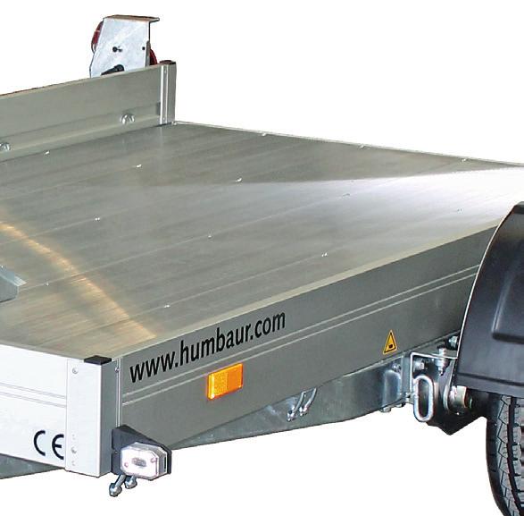
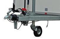
5 Product Description The HKT lowerable trailer with a fixed loading ramp is a transport facility for motorcycles. The HKT lowerable trailer with a ramp door is a universal use transporter for small construction machines. The cargo bed can be lowered and lifted with the aid of a hydraulic pump. The mechanical safety lock prevents the cargo bed from dropping down while driving. The phenolic resin-coated wooden cargo bed ensures that the trailer has a long service life. The low drive-up angle of - 6 facilitates loading. The HKT lowerable trailer is available as a braked or unbraked version. The HKT lowerable trailer has a fixed loading ramp or a full-length ramp door. The load is secured to the recessed lashing points using standard lashing straps. The HKT lowerable trailer permits a wide range of applications for load capacities of 0 kg -,5 kg. The HKT lowerable trailer can be optionally fitted with the following accessories: with 350 mm drop sides, with a tarpaulin/frame body, as a plywood box body or with an aluminium snap-lock, with wheel shock absorbers (for 00 km/h), or with a corrugated aluminium cargo bed. The following illustrations show the special features and spare parts for the HKT lowerable trailers. HKT - unbraked, aluminium cargo bed braked, wooden cargo bed HKT - lowered, from behind Operating Instruction Manual HKT (Part ) Version 0/7 5


.")


 8.")


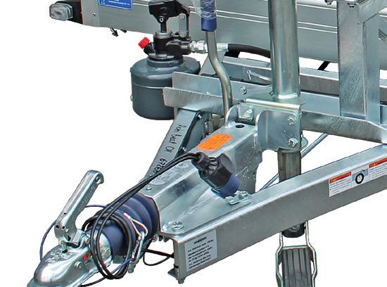
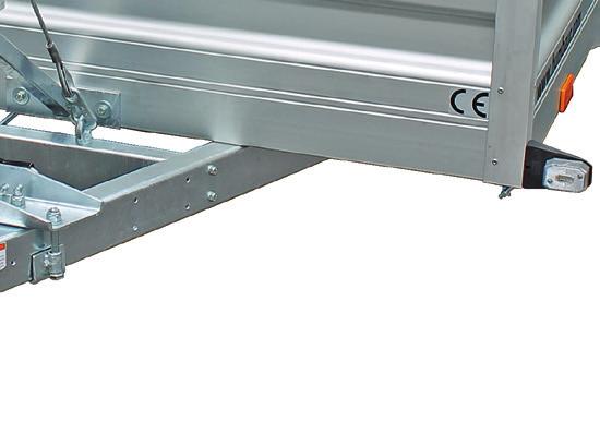
6 HKT - unbraked, with loading ramp. Standard jockey wheel. Electric plug 3. Coupling ball. Safety cable 5. Drawbar support 6. Hand brake / loading ramp 7. V drawbar 8. Pump lever (hydraulic) 9. Locking lever 0. Hydraulic hand pump. Lighting (front). Rear reflector (side) 3. Mudguard. Wheels/tyres/axle 5. Spray flap 6. Wheel chock 7. Tail light (back) 8. Loading ramp 9. Lashing lug 0. Cargo bed. Number-plate holder. Number plate light HKT - from the rear 6 Version 0/7 Operating Instruction Manual HKT (Part )


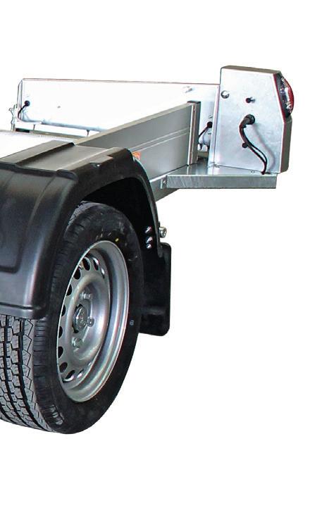
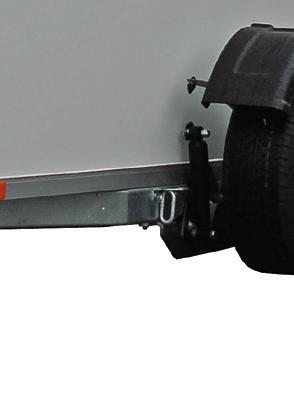
7 3 6 HKT - braked, with ramp door 3. Ramp door. Tail-gate ramp lock 5. Automatic jockey wheel 6. Plywood box body 7. Handle 8. Control strip 9. Gas struts 30. Espagnolette bolt, lockable 3. Tailgate 3. Lashing rail 33. Lashing bracket, movable 3. Snap-lock on ramp door HKT - braked, as a plywood box body Operating Instruction Manual HKT (Part ) Version 0/7 7


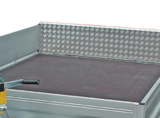
8 Optional accessories With motorcycle stand, centrally positioned. Motorcycle stand, foldable / adjustable With wheel shock absorbers for 00 km/h. Wheel shock absorbers With toolbox on the drawbar. Humbaur toolbox With cable winch and higher side walls. Cable winch, fixed. Drop sides, 350 mm high With tarpaulin and frame body. Full tarpaulin. Frame 8 Version 0/7 Operating Instruction Manual HKT (Part )
9 3 Intended Use Motorcycles may only be transported by using a motorcycle stand. Transporting of small construction machinery / small vehicles, e.g. road sweeper, lawn mower, up to the maximum permissible gross weight. Transporting of secured loads, such as pallets/cases with goods, etc. Transporting loose bulk goods such as gravel and building rubble with trailer version with 350 mm side walls and a ramp door. The towing vehicle must have a minimum coupling height of 0 mm. Foreseeable misuse Transporting loose bulk goods such as sand, wood cuttings, leaves, grass, etc. with the wrong trailer version (with ramp door, no closed box shape). Driving with unsecured ramp door. Driving with the high cover not completely closed. Driving with number plate holder not locked. Driving with cargo bed not locked. Non-observance of the safety instructions in the operating instruction manual, "Trailers up to 3.5 to" (Part ). 6 Loading and Unloading The HKT lowerable trailer is mainly designed for transporting motorcycles and small vehicles. You will mainly find a description of the loading/ unloading process for motorcycles below. 6. Load distribution WARNING Negative/low drawbar load - risk of skidding! If the vehicle is loaded incorrectly, you can create a negative or inadequate drawbar load which causes risk of skidding. Distribute the weight evenly across the trailer. Observe the minimum and maximum drawbar load forces of the trailer. Do not exceed the maximum permissible drawbar load of the towing vehicle and trailer coupling. Observe the information on the maximum permissible vertical load on the drawbar. VORSICHT CAUTION Nichteinhaltung der Stützlast Unfallgefahr / Schlingergefahr! Verteilen Sie die Ladung so, dass keine negative Stützlast entsteht bzw. die Noncompliance with vertical load Risk of accident / skidding! When distributing the cargo, a negative vertical load mustn t arise and the max. 5 General Safety Instructions WARNING Correct load distribution Unsecured cargo bed! An unsecured cargo bed may drop down while driving - accident hazard! Make sure that the cargo bed is secured with the safety lock before driving off. Moving cargo bed! You could fall if you step onto the cargo bed during the loading and unloading process with simultaneous lifting/lowering of the cargo bed. Try not to step onto the cargo bed during the lifting/ lowering process. Take particular care when stepping onto the cargo bed. Vehicle loaded correctly The trailer and the towing vehicle are stable with all wheels on the ground. Optimal driving characteristics and minimum risk of skidding. Incorrect load distribution Use. Vehicle loaded incorrectly Observe the other general safety recommendations in the operating instruction manual, "Trailers up to 3.5 to" (General Points - Part ). The trailer is tilting backwards; the towing vehicle is tilting forwards = the drawbar load is too low or negative. The trailer tends to swerve, which increases the risk of skidding. Operating Instruction Manual HKT (Part ) Version 0/7 9


 on both sides.")

10 6. Load securing Tied-down motorcycle. Lashing strap. Motorcycle stand Centrally position the motorcycle on the motorcycle stand. - Where necessary, first adjust the motorcycle stand. Use suitable lashing straps to tie down the motorcycle at the lashing points. A motorcycle stand may only be retrofitted using the attachment points provided. Fitting should only be carried out by a person with specialised mechanical knowledge and experience in the use of tools and their inherent risks. We recommend that you have the motorcycle stand fitted by a qualified workshop. Position the loading ramp Pull the cotter pin out of the plug bolt. Pull out the plug bolt. Position the loading ramp in accordance with the wheel size of your motorcycle and in line with the base rail. Insert the plug bolt through the axle and align it with the adjustment holes. Insert the cotter pin into the drill-hole of the plug bolt. Read and observe the assembly instructions. Operating the motorcycle stand Folding down the front stop Loosen the screws (wing nuts) on both sides. Position the loading ramp as far forward as possible. Fold down the stop. Insert the retaining screws from the inside. Firmly tighten the wing nuts with their spring washers. Tying down goods Adjusting the motorcycle stand. Front stop, foldable. Wing nut / spring washer / retaining screw 3. Base rail. Adjustment holes 5. Plug bolt with cotter pin 6. Loading ramp Lashing points. Lashing brackets, recessed ( per side). Lashing strap 0 Version 0/7 Operating Instruction Manual HKT (Part )


11 Tie down the load (vehicle). - Do not exceed the maximum lashing force per lashing point, i.e. 00 dan (kg). Take note of the sticker providing information about the maximum tie-down forces on the trailer. DIN Zurrpunkte 00 dan (kg) min Lowering the cargo bed WARNING Lowering of the cargo bed! Crushing hazard for feet at rear of trailer when lowering the cargo bed. Keep persons away from the hazard area during lowering _B Preparing the trailer to be lowered Small vehicle, tied down The trailer should not be able to slip away during the loading process. Place the trailer on solid ground. Secure the trailer so that it cannot roll away or couple it to the towing vehicle first. NOTICE Incorrect operation of the locking lever during the lowering process! The mechanical safety lock for the cargo bed may become deformed, resulting in a loss of function. Motorcycle, tied down Securing a combined load Ideally, secure the load with a combination of form-fitting and force-fitting: - Force-fitted by: Direct tie-down of the load. - Form-fitted by: Supporting the various components of the load against each other, against the drop sides and against the cargo bed extensions, without spaces in-between. Do not apply force to the locking lever. It can be operated without undue force by observing the correct operating sequence. Pay attention to the operating sticker on the trailer. lo Always keep to the specified step sequence. Operating Instruction Manual HKT (Part ) Version 0/7
 3.")


12 Lowering process Lowered positions 3-6 Drive-up angle Operating elements. Pump lever. Locking lever (cargo bed) 3. Insertion openings (top, sides). Valve wheel Remove the pump lever from the retainer. - Insert it into one of the corresponding openings. Move the cargo bed slightly upwards until the locking lever is released (the mechanical safety lock will be released). Cargo bed lowered. Loading ramp 3 Pull on the locking lever without undue force and hold it in place. Cargo bed lowered. Ramp door, folded down Gradually open the valve wheel. - The cargo bed will be lowered. - You can now release the locking lever. Lower the cargo bed completely until it rests on the base. Version 0/7 Operating Instruction Manual HKT (Part )


13 6. Operating the number plate holder CAUTION Crushing hazard! There is a crushing hazard for the fingers / hands when operating the number plate holder. Be careful when operating the number plate holder. Unlocking Cargo bed lowered. Ramp door, folded down (with box extension) 3 5 Locked Unlocked. Number-plate holder. Bracket 3. Locking lug. Lock 5. Cotter pin Pull out the cotter pin. Fold down the lock. Pull the bracket out of the locking lug. Swinging the number plate holder open Cargo bed lowered. Ramp door with high cover / frame extension 6 Opened 6. Bolt Carefully open the number plate holder. - It will rest on a bolt. Locking Rotate the number plate holder towards the cargo bed. Push the bracket onto the locking lug on the loading ramp. Push the bolt until it closes. Insert the cotter pin through the bolt. - Ensure that it engages properly. Operating Instruction Manual HKT (Part ) Version 0/7 3


14 6.5 Operating the ramp door CAUTION Risk of crushing! There is a crushing hazard for the fingers / hands when operating the ramp door. Be careful when operating the ramp door. Hold onto the side of the ramp door when lowering it. Carefully close the ramp door. Ramp door folded down Carefully fold down the ramp door. - Make sure that your feet are not under the ramp door. Folding up / locking 3 HKT with ramp door. Tail-gate ramp lock. Ramp door 3. Number plate light. Number plate holder Fold up ramp door Carefully lift the ramp door. Unlocking / folding down 3 3 Ramp door unlocked. Bolt handle. Bolt bracket 3. Securing hook. Striking plate Locking the ramp door Place the locking bracket onto the striking plate. Push the bolt handle until it closes. - The securing hook will automatically engage. Hold the ramp wall with one hand and close the lock on the other side. Push the securing hook down. Pull the bolt handle towards you and remove the locking bracket while you do so. Hold the ramp wall with one hand and open the lock on the other side. Ramp door in driving position Version 0/7 Operating Instruction Manual HKT (Part )


 3. Stanchion 3 Open the high cover. Belt. Upper holding eyelets / buckle 3.")
15 6.6 Operating the high cover (frame) Releasing / opening the high cover The frame and high cover are inserted into the corner stanchions of the HKT trailer and secured all round the drop sides with staples. CAUTION Risk of impact! A high cover placed onto the frame with a winding shaft may fall down and hit you. When opening the high cover, ensure that the winding shaft is securely placed onto the frame so that it cannot slip; use the upper buckles to secure it where necessary. 3 High cover with loading ramp 3 Releasing the high cover at the back. Securing the high cover at the back. Winding shaft 3. Attachment ring. Safety spring Open the number plate holder and swivel it sideways. Pull out the securing springs on both sides. Carefully release the winding shaft from the attachment rings Closed cover. Eyelet. Belt 3. Cover. Buckle 5. Staple 6. Winding shaft Frame without high cover. Frame. Slats (wood) 3. Stanchion 3 Open the high cover. Belt. Upper holding eyelets / buckle 3. Slat Open the buckles on both sides. Pull the belt upwards out of the eyelets on both sides. Carefully roll up the rear part of the high cover and attach it to the top holding eyelets, using both buckles, or place it onto the roof of the frame during this process, the winding shaft must not fall down. The slats can be removed for loading / unloading. Operating Instruction Manual HKT (Part ) Version 0/7 5


16 High cover with ramp door Operating the "box body" tailgate WARNING Risk of tipping over! When the tailgate is opened, the trailer could tip back - risk of impact / crushing! Couple the trailer to the towing vehicle before opening the tailgate or first lower the cargo bed. CAUTION Mind your head! It is easy to knock your head on the open tailgate Carefully step onto / off the cargo bed. - Duck if necessary. Closed cover. Eyelet. Belt 3. Cover. Buckle, to one side 5. Staple 6. Ramp door 7. Tension rope with hooks Releasing / opening the high cover Release the tension ropes and hooks from the holes in the ramp wall. Open the buckles on both sides. Pull the belt upwards out of the eyelets on both sides. Carefully roll up the rear part of the high cover and use the two buckles to attach it to the upper holding eyelets or place it onto the roof of the frame. Closing / securing the high cover Opening Unlocking the tailgate 3. Locking lugs. Bolt handle 3. Pressure safety device. Safety lock Grip the bolt handle with one hand and push in the pressure protection mechanism. - The bolt handle will be released. Push the bolt handle downwards. - The locking lugs (right and left) are released. Carefully push up the tailgate. Lock the gas strut with the piston retainer. Opening the ramp door Insert the slats. Carefully lower the back of the high cover. Close the buckles on all belts and hook all open staples into the eyelets. Hook the tension ropes into the holes on the ramp door. Carefully insert the winding shaft in the attachment rings and secure the winding shaft, using the securing springs. Unlocking the ramp door 3. Snap locks. Ramp door 3. Locking bracket. Gas strut lock (piston retainer) 6 Version 0/7 Operating Instruction Manual HKT (Part )
17 Ensure that the tailgate is secured with the gas strut lock. Turn the snap-locks upwards on both sides. 6.8 Loading the trailer Make sure that the trailer is secured so that it cannot roll away. - The bolts will move out of their locking brackets. Hold onto the side of the ramp door and carefully lower it. WARNING WARNUNG Closing the ramp door Unzureichende Beleuchtung beim Be- und Entladen! Inadequate lighting during loading and unloading! Erhöhte Unfallgefahr. Sichern Sie den Anhänger mit zusätzlichen Signaleinrichtungen Increased risk of accidents. Secure the trailer with additional signalling devices. Make sure that road traffic safety is not impaired when loading and unloading the trailer. If necessary, use additional signalling devices, e.g. signs, barriers. WARNING Locking the ramp door Stepping onto the cargo bed! Hold onto the side of the ramp door and carefully raise it. Turn the snap-locks downwards. - The bolts will move into their locking brackets. - The ramp door is locked into place. Take particular care when stepping onto the cargo bed. Use Closing the tailgate Gas strut locked You could fall off if you step onto the cargo bed during the loading and unloading process.. unlocked Turn the piston retainer by 80. The piston retainer is unlocked. Loading a motorcycle Carefully push the motorcycle onto the trailer until the front wheel is inside the motorcycle stand. - Observe the section: 6. Load distribution Locking the tailgate Hold the tailgate and step behind it (to the rear of the trailer). Use both your hands to push down the tailgate. - Ensure that the espagnolette lock is open and that the locking cams engage smoothly. Pull up the bolt handle and then push it in firmly. - The bolt handle will automatically lock into the pressure protection mechanism. Where necessary, use a key to secure the safety lock. Tying down / securing a motorcycle Tie down / secure the motorcycle in a standing position. - Observe the section: 6. Load securing Lifting / securing the cargo bed Lift the cargo bed. Secure it, using the safety lock. - Observe the section: 6.8 Lifting the cargo bed Operating Instruction Manual HKT (Part ) Version 0/7 7


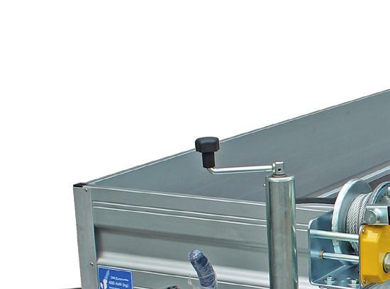
18 6.8. Using the cable winch The cable winch is permanently installed on the drawbar. Defective vehicles can be pulled onto the cargo bed using the cable winch. 3 5 WARNING Using a damaged cable winch! A damaged cable will be weakened and may tear when placed under load. People could be hit or crushed by the rope and/or the load. HKT with cable winch 6 7 Only use the cable winch if it is undamaged and in perfect condition. Regularly have the cable winch serviced and repair it immediately if it is faulty. CAUTION Operating the cable winch! You could crush your hands / fingers in the cable winch while rolling or unrolling the cable. You could lacerate your hands on broken individual wires of the cable.. Cable winch. Crank base 3. Crank. Cable (steel) 5. Snap hook 6. Eyelet 7. Cable winch / frame Extending / unrolling the cable Always use. Only use and undamaged cable. Immediately replace any cable that has broken individual wires. Ensure that your fingers do not get caught in the cable winch when rolling up the cable. NOTICE Overloading the cable winch! Overloading the cable winch may result in breaking it off or tearing the rope. Adhere to the maximum permissible tractive force of the cable winch, i.e. 950 dan or approximately 900 kg. Take note of the type label on the cable winch. 3 Inserting the crank. Securing pin. Crank base 3. Crank. Parking holder for crank Pull on the securing pin, while at the same time removing the crank from its parking position. Insert the crank into the crank base. - Simultaneously pull out the securing pin and place it into one of the holes. Relax the cable by turning the crank in an anti-clockwise direction. Unroll the cable 8 Version 0/7 Operating Instruction Manual HKT (Part )


19 Unhook the snap hook from the eyelet. Manually extend the cable. - Ensure that the crank turns. - If necessary, remove the crank beforehand. Pull up the vehicle, using the cable winch Make sure that the trailer is secured so that it cannot roll away. First couple the trailer to the towing vehicle! 6.9 Lifting the cargo bed WARNING Lifting the cargo bed! Crushing hazard for hands when lifting the cargo bed in the wheel area. Keep people away from the hazard zone during lifting. Fasten the snap hook to the tow ring of the vehicle to be loaded / unloaded. Turn the crank in a clockwise direction - the cable rolls up and pulls the vehicle onto the cargo bed. - Ensure that the vehicle is centrally mounted on the cargo bed. Do not reach into the hazard zone during the lifting process. Roll up the cable and secure it CAUTION Unsecured cable / crank! An unsecured cable / crank may rattle around while driving, be torn off and hit a person. Before driving off, ensure that the cable is fastened in the eyelet with the snap hook and pulled tight. Ensure that the crank is in the parked position and secured with the securing pin. NOTICE Incorrect operation of the locking lever during the lifting process! The mechanical safety lock for the cargo bed may become deformed, resulting in a loss of function. Pump until the locking lever automatically engages. Release the hydraulic system. - The cargo bed must rest on the mechanical locking bolts. Pay attention to the operating sticker on the trailer. lo Always keep to the specified step sequence. Cable rolled up / secured Insert the snap hook into the eyelet. Slightly tighten the cable. Remove the crank from the crank base. Place the crank into the parking holder and ensure that it points in the right direction. - Ensure that the crank has been secured. Operating Instruction Manual HKT (Part ) Version 0/7 9
20 Lifting process 6.0 Unloading the trailer Make sure that the vehicle to be unloaded is secured from rolling away. - e.g. handbrake pulled up, wheel chocks positioned. Operating elements. Pump lever. Locking lever (cargo bed) 3. Insertion openings (top, sides). Valve wheel Lower the cargo bed. Release all lashing straps and stow them away. Open the ramp door / tailgate / number plate holder. Slowly roll or drive the motorcycle / load down the ramp. Close the valve wheel. Lift the cargo bed completely until the locking lever automatically moves into the driving position. - The locking lever must remain movable. Briefly open and close the valve wheel. - The hydraulic system is released. Check whether the locking lever can be moved. - It should fit firmly. - The cargo bed is mechanically secured by locking bolts. Close the ramp door / tailgate / number plate holder and secure them. Lift the cargo bed. 3 Insert / secure the pump lever. Drill-hole in crossbar. Pump lever 3. Safety device (cotter pin, cable) Insert the pump lever into the drill-hole and bolt. Insert the cotter pin through the securing bolt. Close the ramp door / number plate holder. (see Section 6. or 6.5) 0 Version 0/7 Operating Instruction Manual HKT (Part )
 are not exceeded.")

\".")


21 7 Driving Before setting off, make sure that the maximum permissible loads (load capacity and drawbar load) are not exceeded. Observe the maximum permissible towing load and drawbar load of your towing vehicle and the trailer coupling. 8 Parking Observe the general safety and warning instructions on parking your trailer safely in the operating instruction manual "Trailers up to 3.5 to (General Points - Part )". If necessary, check the weight information for the goods to be loaded (vehicle). Parking and securing the unbraked trailer 3 Vehicle secured Carry out a departure check (see operating instruction manual, "Car Trailers" (General Points - Part )) Parking and securing the braked trailer. Wheel chock. Standard jockey wheel 3. Automatic jockey wheel. Hand brake In addition, make sure that - the cargo bed has been lifted up. - the safety lock of the cargo bed is functional. - the ramp door / tailgate / number plate holder are all closed and secured. With the trailer brake applied, pull the handbrake on. Trailer coupled and ready for operation Check that: - the cargo bed, - the ramp door or number plate holder, - the accessories / tie-down equipment, - the motorcycle stand, - the pump lever, - the high cover, - the tailgate (for box extension) are secured. - The jockey wheel has been tilted up and secured. - The toolbox has been locked. Operating Instruction Manual HKT (Part ) Version 0/7
22 9 Cleaning/Maintenance/Servicing 9. Care/Cleaning Observe the safety instructions and instructions for general cleaning/care of trailers in the operating instruction manual, "Car Trailers" (General Points - Part ). CAUTION Crushing hazard! During the cleaning process, there is a risk of crushing your fingers/hands in the lowering mechanism. Cutting hazard! During the cleaning process, there is a risk of crushing your fingers/hands in the lowering mechanism. Do not touch the movable mechanical components when lowering / lifting the cargo bed. - Do not reach into it. Clean lowering mechanism / wheel shock absorbers 9. Maintenance/Servicing 9.. Tyres/Wheels The following tyre sizes can be used on HKT trailers: Tyre type p max. in bar 95 / 50 R 3 C 6.5 Table: Tyre size / Tyre pressure Check the tyre pressure on all wheels on a regular basis and before long journeys. (See the table: "Maintenance instructions" in the operating instruction manual, "Car Trailers" (General Points - Part )) 9.. Lowering mechanism / wheel shock absorbers The wheel shock absorbers are virtually maintenance-free. The damping effect will decrease after long periods of use and long intervals of use. The lowering mechanism / wheel shock absorbers and their fixings need to be regularly checked for oil leaks, damage, ageing, breakage and material fatigue. Servicing work must only be carried out by qualified specialists. The service life, functionality and safety of your trailer depends to a large extent on the regular maintenance/care of the lowering mechanism. 3 Lowering mechanism 3 Lowering mechanism / wheel shock absorbers. Attachment: Fender bracket. Attachment: Positioning bolt 3. Attachment: Wheel shock absorbers. Attachment: Positioning angle (drill hole). Positioning bolt. Fender bracket 3. Wheel shock absorbers. Positioning drill-hole During spraying, do not aim the water jet directly at the wheel shock absorbers. Check for any soiling of the lowering mechanism / wheel shock absorbers and remove if necessary each time after you use the trailer. Clean the lowering mechanism in the lowered state with a clean dry cloth. Do not scratch or paint the wheel shock absorbers or treat them with corrosive media (abrasives). Ensure that the screw connections have been firmly attached. - Retighten the screws if necessary. Check the wheel shock absorbers for oil leaks. If the absorption effect is reduced or if there are visible oil leaks, replace the wheel shock absorbers. Use only genuine spare parts, see designation / type no. on the wheel shock absorbers. Ensure that the positioning bolts fit smoothly into the positioning drill-hole. - Adjust the positioning angle if necessary. Version 0/7 Operating Instruction Manual HKT (Part )
. 9.")


23 9..3 Locking device WARNING Worn / deformed locking device! The cargo bed may drop down while driving (accident hazard). 9.. Cable winch The cable winch must be inspected by specialised staff at least once a year or every 0,000 km. If the cable winch is subject to heavy-duty use or operating conditions, the inspection intervals must be shorter. Carry out regular checks and adjustment of the locking device. The checking interval depends on the frequency of use of your trailer. However, you should carry out a check at least every 6 months. The cable winch and its attachment must be checked for damage / crushing, ageing, broken individual wires or the cable as a whole and material fatigue. Servicing work must only be carried out by qualified specialists. 3 Check and grease the transmission cables. Fastening nuts. Tensioning screw 3. Transmission cable of locking lever. Locking lever bearings Check the operating point of the locking device for signs of wear, loose connections, corrosion, foreign objects. Ensure that the movement of the locking lever is transmitted without play. Retighten the transmission cables if necessary. - Loosen the fastening nuts on each cable winch. - Retighten the tensioning screws. - Firmly tighten the fastening nuts. Check the function of the locking lever. - Lift and lower the cargo bed at least twice. Apply a little multi-purpose grease to the transmission cables, if necessary. Grease the locking lever bearings. Testing / greasing the cable winch 9.. Number plate holder. Cable (steel). Gear segment. Attachment nut Check that the holder is firmly attached. - Retighten the nuts if necessary. Completely extend the cable and clean both the cable and the gear segments with a clean cloth. Carry out a visual inspection for damage / tears / cracks. - In the event of damage, have the cable winch repaired by specialised staff. Use a commercial machine grease to grease the cable slightly. Carefully wind the cable onto the drum. Operating Instruction Manual HKT (Part ) Version 0/7 3
24 0 Troubleshooting Use the fault rectification table to repair the specific operating functions of the HKT trailer in the event of a fault. For further causes of faults and rectification measures, see the operating instruction manual "Trailers up to 3.5 to (General Points - Part )". Decommissioning/disposing of the trailer Observe the safety instructions for decommissioning / disposal of trailers in the operating instruction manual, "Trailers up to 3.5 to" (General Points - Part ).. Decommissioning the trailer WARNING Unsecured trailer! Unexpected start! Do not go under the chassis when troubleshooting. There is a danger of you being crushed if the trailer starts to move unexpectedly. Make sure that the trailer is secured so that it cannot roll away. Do not actuate the cargo bed whilst you or anyone else are under the chassis. Secure your trailer against unauthorised use by third parties, e.g. using wheel clamps. Park your trailer so that it cannot cause any further hazards for third parties, e.g. by tipping over, rolling away, or causing a traffic obstruction.. Disposal Take the individual parts or the entire trailer to a car/ vehicle recycling facility. The specialists at the car/vehicle recycling facility will dispose of the individual components in the proper manner. Malfunction Possible cause Solution Cargo bed does not lower. - The locking lever does not release. Move the cargo bed to its top position until the locking lever can be moved. - The locking mechanism is maladjusted. - The coupling height of the towing vehicle is too low (< 0 mm). Adjust the tensioning cables of the locking mechanism. Check the coupling height of the towing vehicle. Adjust the required height or exchange the towing vehicle for one with a suitable coupling height. Cargo bed does not rise up. - The valve wheel of the hydraulic pump is open. Close the valve wheel of the hydraulic pump. Lift the cargo bed. Mudguards not properly positioned - jammed. - The attachment angle is wrong and the positioning bolt is maladjusted. - The positioning bolt is deformed. Check the position of the attachment brackets with positioning holes and adjust where necessary. Exchange the positioning bolt. Fault repair table Version 0/7 Operating Instruction Manual HKT (Part )
25 "Quality made in Germany " Operating Instruction Manual HKT (Part ) Version 0/7 5
26 Competence in Trailers No liability is accepted for errors or printing errors. All illustrations are representative. Deviations and modifications are subject to the model type. Subject to change without notice. Copying prohibited. Printed in Germany. Version 0/7
Operating instructions
 Vehicle transporter Operating instructions Part 2 - FTK en 4000 series Name and address of manufacturer: Humbaur GmbH Mercedesring 86368 Gersthofen Germany Tel. +49 82 24929-0 Fax +49 82 249-00 info@humbaur.com
Operating Instructions
 Single-axle wheels-in trailer Operating Instructions Part - HU, HN en 000 Series Name and address of manufacturer: Humbaur GmbH Mercedesring 86368 Gersthofen Germany Name and address of dealer: Name: Address:
Flatbed trailers and wheels-in trailers Tandem trailers and turntable trailers. Light professional trailers up to 3.5 t.
 Flatbed trailers and wheels-in trailers Tandem trailers and turntable trailers Light professional trailers up to 3.5 t 2000 series 1 Allow us to convince you Our arguments make it easy for you to become
Tippers & Transporters
 Multitalents up to 3.5 t Tippers & Transporters Rear and three-way tippers / Construction machine transporters HUMBAUR CAR TRAILERS 3000/3500 series humbaur.com 3000/3500 series Info Follow Humbaur! Because
WAP disc brake technology. Assembly, operating and maintenance instructions
 WAP disc brake technology Assembly, operating and maintenance instructions Number MA-025 Date 22.07.2010 1 Please read this operating and service manual before starting the vehicle. It forms part of the
SINgLE-AxLE TRAILERS SERIES TRAILERS RANgE UP TO 3.5 to. Illustrations may contain special equipment /
 SINgLE-AxLE TRAILERS Illustrations may contain special equipment / products are subject to continuous technical modifications 1000 SERIES TRAILERS RANgE UP TO 3.5 to www.humbaur.com 1000 SERIES CONTENTS
23-TV25 TIPPING TRAILER CAREFULLY READ THE OPERATING INSTRUCTIONS BEFORE USING THE PRODUCT! OPERATING INSTRUCTIONS TRANSLATED FROM ORIGINAL
 23-TV25 TIPPING TRAILER CAREFULLY READ THE OPERATING INSTRUCTIONS BEFORE USING THE PRODUCT! OPERATING INSTRUCTIONS TRANSLATED FROM ORIGINAL INTRODUCTION Thank you for choosing a product from Kellfri AB.
Motorcycle, vehicle and universal transport trailers
 Motorcycle, vehicle and universal transport trailers from 750 kg to 3.5 t 4000 series 1 2 Maintain an overview Table of Contents Allow us to convince you... 4 On the street and at home... 6 Motorcycle
HST -LS Interlocking device (Translation of Original Manual)
") Installation and Operating Manual for Components HST -LS Interlocking device (Translation of Original Manual) HST-LS Ident.-No.: 10268 HST-LS Ident.-No.: 10269 HST-LS, pictured Ident-Nr. 10269 The image
Installation and Operating Manual for Components HST -LS Interlocking device (Translation of Original Manual) HST-LS Ident.-No.: 10268 HST-LS Ident.-No.: 10269 HST-LS, pictured Ident-Nr. 10269 The image
CARGO ALL PLANT CREATED FOR CONSTRUCTION YOUR TRANSPORT ASSISTANT
 44 45 CARGO ALL PLANT CREATED FOR CONSTRUCTION YOUR TRANSPORT ASSISTANT CarGO All Plant epitomises the Brian James Trailers approach to providing solutions. There is nothing included that is not needed
Instructions for Fitting, Operating and Maintenance Canopy Door RE / (St.: )
") EN Instructions for Fitting, Operating and Maintenance Canopy Door 1 818 012 RE / (St.: 12.2010) 12.2010 ENGLISH Contents 1 Safety Instructions... 3 1.1 Qualified persons... 3 1.2 Symbols and signal words
EN Instructions for Fitting, Operating and Maintenance Canopy Door 1 818 012 RE / (St.: 12.2010) 12.2010 ENGLISH Contents 1 Safety Instructions... 3 1.1 Qualified persons... 3 1.2 Symbols and signal words
CARGO ALL PLANT Constructed to get the job done.
 » Connected to you CARGO ALL PLANT Constructed to get the job done. UNITED KINGDOM CARGO ALL PLANT CREATED FOR CONSTRUCTION YOUR TRANSPORT ASSISTANT CarGO All Plant epitomises the Brian James Trailers
REX & MU.T tiltable trailers series
 REX & MU.T tiltable trailers series tilting angle steplessly inclinable trailer available in 3 lengths: 2,10 m 2,51 m 3,01 m TILTABLE TRAILERS FOR ANYBODY. The four versions. REX 21 REX 25 internal length
FOREST TRAILER PALMS 9S
 USER MANUAL FOREST TRAILER PALMS 9S Palmse Mehaanikakoda, Võsupere küla, Vihula vald, Lääne-Virumaa 45202, Estonia tel. +3723255375 fax +3723255378 e-mail: palms@palms.eu http://www.palms.eu TABLE OF CONTENTS
HYDRAULIC PALLET TRUCK MODEL NO: PT540M/BM/CM & PT685BM/CM PART NO: , , , ,
 HYDRAULIC PALLET TRUCK MODEL NO: PT540M/BM/CM & PT685BM/CM PART NO: 7631700, 7631705, 7631710, 7631715, 7631720 OPERATION & MAINTENANCE INSTRUCTIONS LS0316 INTRODUCTION Thank you for purchasing this CLARKE
Trailers for the. Construction Programme. may include special features. Similar to illustration /
 Trailers for the construction industry Similar to illustration / may include special features SERIES 10000 Construction Programme www.humbaur.com 10000 Series CONTENTS 10000 Series Overview Tandem Flatbed
INSTALLATION / OPERATING INSTRUCTIONS Reese Elite Series FIFTH WHEEL SLIDER HITCH
 INSTALLATION / OPERATING INSTRUCTIONS Reese Elite Series FIFTH WHEEL SLIDER HITCH DEALER/INSTALLER: (1) Provide this Manual to end user. (2) Physically demonstrate hitching and unhitching procedures in
Operating instructions ErgoPack 600 E
 Operating instructions ErgoPack 600 E Operation of the device is only permitted if the operating instructions have been carefully read and understood before use! Declaration of conformity EU declaration
Original Operating Manual
 matev GmbH Nürnberger Str. 50 90579 Langenzenn T +49 (0) 9101 9087-0 F +49 (0) 9101 9087-20 info@matev.eu www.matev.eu Original Operating Manual Snow blade SRM-FB 120 CD Angle adjustment mechanical Version
Original Operating Manual
 matev GmbH Nürnberger Str. 50 90579 Langenzenn T +49 (0) 9101 9087-0 F +49 (0) 9101 9087-20 info@matev.eu www.matev.eu Original Operating Manual Front Power System und Front PTO shaft FPS- JD X 950 R for
Flatbed trailers and semi-trailers
 Trailers from 24 t to 50 t Flatbed trailers and semi-trailers Turntable trailers / Flatbed semi-trailers HUMBAUR HEAVY SCHWERLAST DUTY 10000 series humbaur.com 10000 series Introduction Follow Humbaur!
OWNER S MANUAL. Sentry & Sentry CT THREE YEAR WARRANTY. Phone: ( ) Fax: (605) SAFETY INSTRUCTIONS
 Fax: (605) SAFETY INSTRUCTIONS") OWNER S MANUAL Sentry & Sentry CT HARD ROLL-UP TRUCK BED COVER SAFETY INSTRUCTIONS 1. Do not place objects on or against cover or framework. 2. Do not tie cargo to truck bed cover framework. 3. Never allow
OWNER S MANUAL Sentry & Sentry CT HARD ROLL-UP TRUCK BED COVER SAFETY INSTRUCTIONS 1. Do not place objects on or against cover or framework. 2. Do not tie cargo to truck bed cover framework. 3. Never allow
Fitting Instruction for EZI-GRIP Bike Rack
 Fitting Instruction for EZI-GRIP Bike Rack Congratulations on purchasing Ezi-Grip to carry your valued bicycles. We are sure you will get many years of enjoyable use from your Ezi-Grip Bike Rack. These
Read the owner s manual completely before you use the trailer.
 OWNER S MANUAL Read the owner s manual completely before you use the trailer. MODEL MPT-UM6096 IMPORTANT SAFETY CHECK LIST PLEASE NOTE: Trailers are not generally used every day. A trailer may sit for
Guidelines for inspection and servicing. VBG MFC coupling 2018
 Guidelines for inspection and servicing VBG MFC coupling 208 General information General The components used to connect a vehicle and trailer are exposed, even during normal use, to very high tensions.
USER MANUAL PRODUCT CODE: WC CareCo (UK) Ltd, Hubert Road, Brentwood, Essex, CM14 4JE PAGE 1
 Ltd, Hubert Road, Brentwood, Essex, CM14 4JE PAGE 1") by USER MANUAL PRODUCT CODE: WC01059 CareCo (UK) Ltd, Hubert Road, Brentwood, Essex, CM14 4JE PAGE 1 CONTENTS 1. INTRODUCTION 2. IDENTIFICATION OF PARTS 3. SAFETY REGULATIONS 4. SAFETY WARNINGS 5. USER
by USER MANUAL PRODUCT CODE: WC01059 CareCo (UK) Ltd, Hubert Road, Brentwood, Essex, CM14 4JE PAGE 1 CONTENTS 1. INTRODUCTION 2. IDENTIFICATION OF PARTS 3. SAFETY REGULATIONS 4. SAFETY WARNINGS 5. USER
CDL Series Pre-Trip Inspection AT-TC3TS T1-JA01. Pre-Trip Inspection Checklist
 Pre-Trip Inspection Checklist This checklist covers different parts of the vehicle you would check before a trip. Note that some specifications described in the following content may not be the same as
RINK Model 1622 Series number:
 OPERATION MANUAL AND LIST OF PARTS RINK Model 1622 Series number: WARNING: IN ORDER TO ENSURE SAFE USE OF THE MACHINE AND OPTIMAL RESULTS, IT IS ESSENTIAL TO READ THIS OPERATION MANUAL CAREFULLY BEFORE
Basic Towing Guide. Lexus Towing Guide
 Basic Towing Guide Lexus Towing Guide IMPORTANT NOTICE Please read: Lexus Australia has used its best endeavours to ensure this material is accurate at the time of printing. However, all information must
INSTRUCTION MANUAL 16K - Fifth Wheel Hitch
 You can take it with you. INSTRUCTION MANUAL 16K - Fifth Wheel Hitch Product No. 30047 DEALER/INSTALLER: END USER: (1) Provide this Manual to end user. (2) Physically demonstrate hitching and unhitching
CARGO SHIFTER Tough and uncompromised multi-purpose mover.
 » Connected to you CARGO SHIFTER Tough and uncompromised multi-purpose mover. UNITED KINGDOM CARGO SHIFTER TOUGH AND UNCOMPROMISED MULTI-PURPOSE MOVER Brian James Trailers have created CarGO Shifter's
LOADING THE TDRT WARNING LOADING/UNLOADING OPERATION
 0012.3 00 LOADING THE TDRT WARNING LOADING/UNLOADING OPERATION All persons not involved in the loading or unloading operation must stand clear the full length of prime mover and Tilt Deck Recovery Trailer.
Installation Instructions
 PIN BOX SHOWN ASSEMBLED Equipment Required: Fastener Kit: ST100F Wrenches: 15/16, 1 1/8 Drill Bits: Not Required White Lithium Grease, Torque Wrench Installation Instructions DEALER/INSTALLER: (1) Provide
AC 100. Operating instructions Pneumatic Crimper AC 100. Date of issue: 05/2010. Keep for future use!
 Operating instructions Pneumatic Crimper AC 100 Date of issue: 05/2010 Keep for future use! SAFETY SAFETY Basic information The basic prerequisite for ensuring safe use and continuous operation of the
Safety check e Safety and function test...to be kept in the cab
 Safety check 38-123305e 2008-12-15 Safety and function test...to be kept in the cab Warning! Never put your fingers into the coupling mouth due to the danger of them being crushed. An open coupling always
SIDE PULL WINCHING WITH THE 35K WINCH TWO PART LINE WARNING
 0011.4 00 90 SIDE PULL WINCHING WITH THE 35K WINCH TWO PART LINE WARNING Performing a 35K Winch 90 Degree Side-Pull with the FWTRD should be performed ONLY after determining that a straight line pull configuration
Operating instructions Assembly instructions
 MOBILITY MADE SIMPLE! Adapter & Adaptation Operating Instructions Operating instructions Assembly instructions Adapter & adaptation for NJ1 e-assistant, NJ1 adaptive bike, SPIKE adaptive bike and FREEWAY
OPERATION & MAINTENANCE INSTRUCTIONS
 10 TONNE HEAVY DUTY LONG CHASSIS TROLLEY JACK MODEL NO: CTJ10GLS PART NO: 7623095 OPERATION & MAINTENANCE INSTRUCTIONS LS0915 INTRODUCTION Thank you for purchasing this CLARKE 10 Tonne Heavy Duty Long
CARGO SHIFTER TOUGH AND UNCOMPROMISED MULTI-PURPOSE MOVER
 36 37 CARGO SHIFTER TOUGH AND UNCOMPROMISED MULTI-PURPOSE MOVER Brian James Trailers have created CarGO Shifter's every detail to deliver the ultimate performance and operating benefit. Strong but light
Operating Instructions 20 Ton Air/Hydraulic Service Jack
 MODEL: 3225 Operating Instructions 20 Ton Air/Hydraulic Service Jack WARNING: Important: Read these instructions and all warnings prior to using this equipment. Understand all operating procedures, safety
Installation, Operating and Maintenance Instructions Retractable Door / Art.-Nr.:
 Installation, Operating and Maintenance Instructions Retractable Door 06.2008 / Art.-Nr.: 1 818 024 ENGLISH CONTENTS PAGE 1 SAFETY REQUIREMENTS 3 1.1 Symbols and key words used 3 1.2 Designated use 3 1.3
Basic Towing Guide. Toyota Towing Guide
 Basic Towing Guide Toyota Towing Guide IMPORTANT NOTICE Please read: Toyota Australia has used its best endeavours to ensure this material is accurate at the time of printing. However, all information
Instructions for Fitting, Operating and Maintenance
 EN Instructions for Fitting, Operating and Maintenance Retractable Door 1 818 024 RE / 10.2011 ENGLISH Contents 1 Safety Instructions... 3 1.1 Qualified persons... 3 1.2 Symbols and signal words used...
Operator s Manual. GreenTek Ltd Rudgate Walton Leeds LS23 7AU UK
 Easy-Load Operator s Manual GreenTek Ltd Rudgate Walton Leeds LS23 7AU UK Certificate of CE Conformity Date: 10 February 2003 Machine Model: Description: Easy-Load High Tipping Trailer Serial Number: I
HEAVY DUTY WHEEL LIFTER
 OWNER S MANUAL PRODUCT CODE: BTWD750 HEAVY DUTY WHEEL LIFTER Capacity Lift Arm Lifting Tilt Range Dimensions Net (Max) Spread Range (degrees) (L x W x H) Weight 750kg 533-635mm 60-275mm -2.5-10mm 787x1092x895mm
ABACO MACHINES OPERATION MANUAL STONE/STEEL/GLASS/WOODS LIFTER (ASSGWL20) ABACO MACHINES (USA)
 ABACO MACHINES (USA)") ABACO MACHINES OPERATION MANUAL STONE/STEEL/GLASS/WOODS LIFTER (ASSGWL20) ABACO MACHINES (USA) 14508 S. Garfield Ave., Paramount, CA 90723, USA Tel : 310-532-0366 Fax : 310-532-99 Email : sales@abacomachines.com
ABACO MACHINES OPERATION MANUAL STONE/STEEL/GLASS/WOODS LIFTER (ASSGWL20) ABACO MACHINES (USA) 14508 S. Garfield Ave., Paramount, CA 90723, USA Tel : 310-532-0366 Fax : 310-532-99 Email : sales@abacomachines.com
3 Axles and brakes. 3.1 Function and construction of the axles Construction Function
 3 Axles and brakes 3.1 Function and construction of the axles 3.1.1 Function Each wheel has an independent suspension system in the axle body (1), so that individual wheel suspension is provided. The swinging
RO Automatic trailer coupling. Repair instructions. 5KPVM02000 Towing Hitch Automatic Rockinger RO244A
 utomatic trailer coupling Repair instructions 5KPVM02000 Towing Hitch utomatic Rockinger RO244 5KPVM02010 Towing Hitch utomatic Rockinger foot operated RO244L Contents 1 General Validity and application
2 TONNE TROLLEY JACK
 2 TONNE TROLLEY JACK 61829 IMPORTANT: Please read these instructions carefully to ensure the safe and effective use of this product and save these instructions for future reference. This manual has been
Mounting Tools 2 Checking Clearances 3 Components 4-5 Mounting 6-21 Correct Method of Tensioning the Chain 22 Adjusting The Overall Dimension 23-24
 Mounting Tools 2 Checking Clearances 3 Components 4-5 Mounting 6-21 Correct Method of Tensioning the Chain 22 Adjusting The Overall Dimension 23-24 Maintenance 25 Repairing Main Body Patterns 26 Removal
Instruction Manual For Auto Shift Hydraulic Lift Table
 Instruction Manual For Auto Shift Hydraulic Lift Table Model Number: CART-550-AS Note: Owner/Operator must read and understand this Instruction Manual before operating the lift & tilt table. Contents 1
HYDRAULIC BENCH PRESS 50,000kg
 OWNER S MANUAL PRODUCT CODE: 2037T HYDRAULIC BENCH PRESS 50,000kg Working Capacity Height Width Depth Weight 50,000kg 1660mm 1220mm 800mm 236kg Made in China to TQB Brands Pty Ltd specifications WARNING
-ty EYDESCREEN MANUF=ACTUFIINC. Operating lnstructions MANUAL
 -ty EYDESCREEN MANUF=ACTUFIINC Operating lnstructions MANUAL Operating Instructions MANUAL All rights reserved, in particular the right to duplicate and distribute and to translate the present document.
OWNER S MANUAL. Sentry & Sentry CT THREE YEAR WARRANTY. Phone: ( ) Fax: (605) SAFETY INSTRUCTIONS
 Fax: (605) SAFETY INSTRUCTIONS") OWNER S MANUAL Sentry & Sentry CT HARD ROLL-UP TRUCK BED COVER SAFETY INSTRUCTIONS 1. Do not place objects on or against cover or framework. 2. Do not tie cargo to truck bed cover framework. 3. Never allow
OWNER S MANUAL Sentry & Sentry CT HARD ROLL-UP TRUCK BED COVER SAFETY INSTRUCTIONS 1. Do not place objects on or against cover or framework. 2. Do not tie cargo to truck bed cover framework. 3. Never allow
CARGO DIGGER PLANT Tough and durable, intelligent and useful.
 » Connected to you CARGO DIGGER PLANT Tough and durable, intelligent and useful. UNITED KINGDOM CARGO DIGGER PLANT TOUGH AND DURABLE INTELLIGENT AND USEFUL The innovative CarGO Digger Plant provides a
STRUT SPRING COMPRESSOR
 OWNER S MANUAL PRODUCT CODE: 1221T STRUT SPRING COMPRESSOR Capacity Stroke Spring Coil Spring Spring Coil Net Weight (Maximum) Thickness Length Diameter 1,000kg 330mm 10-18mm 210-570mm 100-158mm 36kg Made
SERVICE MANUAL. Hollandia 300 Large
 SERVICE MANUAL Hollandia 300 Large 1 BEFORE BEGINNING THE SERVICE PROCEDURE 1. Determine which model of the Hollandia 300 Large is installed in the vehicle. 2. Diagnose the problem by using the Trouble
INSTRUCTION MANUAL TITAN 16K - Fifth Wheel Hitch Plymouth MI
 You can take it with you. INSTRUCTION MANUAL TITAN 16K - Fifth Wheel Hitch Plymouth MI Product No. 30866 DEALER/INSTALLER: END USER: (1) Provide this Manual to end user. (2) Physically demonstrate hitching
20 TONNE HYDRAULIC PRESS MODEL NO: CSA20FBT
 20 TONNE HYDRAULIC PRESS MODEL NO: CSA20FBT PART NO: 7614058 OPERATION & MAINTENANCE INSTRUCTIONS WARNING: Read these instructions before using the press GC0516 INTRODUCTION Thank you for purchasing this
Assembly and Maintenance Manual Type ASNU
 Assembly and Maintenance Manual Type ASNU Hatschekstr.36 69126 Heidelberg Germany Tel +49(0)6221 30470 Fax +49(0)6221 304731 info@stieber.de www.stieber.de Date of issue: 30.05.2018 GB Revision: 0 U:\EngUsers\!ProduktDoku\1AAA_Einbauerklaerung_Wartungsanleitung_Konformitaetserklaerung\1AAA_Wartungsanleitungen\Orginal_Worddatei\_ASNU.docx
Owner s Instructions and Safety Manual. Double-Double series. Performance Bicycle Trailers
 Owner s Instructions and Safety Manual Double-Double series TM Performance Bicycle Trailers Contents 1. Trailer Components 2. Tow Bar and Hitch Components 3. Assembling Your Trailer 4. Attaching the Wheels
TRAILER PASSPORT. instruction manual maintenance warranty
 TRAILER PASSPORT instruction manual maintenance warranty trailer model article no. vehicle identity number initial registration date of transfer name and signature of your respo representative 1 Congratulations!
Directions for use VIBRO FLEX 7400
 Directions for use VIBRO FLEX 7400 Contents Introduction... 3 Identification... 3 Explanation of symbols... 4 Safety... 5 General safety advice... 5 Coupling and uncoupling... 5 Three-point hitch or linkage...
Translation of the Original operating instructions Lifting device Z 70 /...
 Translation of the Original operating instructions Lifting device Z 70 /... Content 1. Lifting device / Correct use according to regulations 2. Basic principles 3. General information 4. Special remarks
3 Ton Trolley Jack. Please read and fully understand the instructions in this manual before operation. Keep this manual safe for future reference.
 Please dispose of packaging for the product in a responsible manner. It is suitable for recycling. Help to protect the environment, take the packaging to the local amenity tip and place into the appropriate
CARGO DIGGER PLANT TOUGH AND DURABLE INTELLIGENT AND USEFUL
 60 61 CARGO DIGGER PLANT TOUGH AND DURABLE INTELLIGENT AND USEFUL The innovative CarGO Digger Plant provides a solution for diggers and plant machinery. Transporting machines, requires a reliable, capable
GARAGE JACK MODEL NO: CTJ3000QLB PART NO: OPERATION & MAINTENANCE INSTRUCTIONS ORIGINAL INSTRUCTIONS
 GARAGE JACK MODEL NO: CTJ3000QLB PART NO: 7623205 OPERATION & MAINTENANCE INSTRUCTIONS ORIGINAL INSTRUCTIONS GC1216 2 INTRODUCTION Thank you for purchasing this CLARKE Garage Jack. Before attempting to
Owner s Instructions and Safety Manual. Switcharoo series. Performance Bicycle Trailers
 Owner s Instructions and Safety Manual Switcharoo series TM Performance Bicycle Trailers Contents 1. Trailer Components 2. Tow Bar and Hitch Components 3. Assembling Your Trailer 4. Attaching the Wheels
16K Reese Revolution. Operating Instructions
 Operating Instructions DEALER: (1) Provide this Manual to end user END USER: (1) Read and follow this Manual every time you use Sidewinder. (2) Save this Manual for Future Reference. PIN BOX SHOWN ASSEMBLED
OPERATING INSTRUCTIONS (Translation) Hoisting crane
 Hoisting crane") 1. User Groups Duties Operator Operation, visual inspection Specialist personnel OPERATING INSTRUCTIONS (Translation) Hoisting crane Type 4781.0,25 Assembly, disassembly, repair, maintenance Tests GB Qualifications
1. User Groups Duties Operator Operation, visual inspection Specialist personnel OPERATING INSTRUCTIONS (Translation) Hoisting crane Type 4781.0,25 Assembly, disassembly, repair, maintenance Tests GB Qualifications
INSTALLATION INSTRUCTIONS
 INSTALLATION INSTRUCTIONS WARNING: NEVER EXCEED YOUR VEHICLE MANUFACTURER'S RECOMMENDED TOWING CAPACITY A20 5TH WHEEL HITCH TABLE OF CONTENTS Page# Description 1 Warnings & Precautions 2 - Assembly & Installation
5 CAR TRUCK SUPERSTRUCTURE DRIVERS INSTRUCTION MANUAL
 5 CAR TRUCK SUPERSTRUCTURE DRIVERS INSTRUCTION MANUAL Britain s premier Car Transporter manufacturer FOR THE ULTIMATE IN QUALITY AND SERVICE PLEASE CONTACT US AT The Old Airfield, Gosfield, Halstead, Essex
Installation instructions
 Service Installation instructions Audi A3 (8V3) 2012 Roof bars 8V3.071.126 for vehicles with bright moulding package (PR no. 4ZB) and roof bars 8V3.071.126.L for vehicles with black moulding package (PR
Load Securing at Mohn Media Mohndruck GmbH
 EXTERN Last updated: 1.2018 Guideline Load Securing at Mohn Media Mohndruck GmbH Content 2 Preface Scope Legal foundations 3 Vehicle requirements General vehicle requirements Securing Material Truck condition
CARGO SHIFTER Configure on demand, meet changing needs.
 » Connected to you CARGO SHIFTER Configure on demand, meet changing needs. UNITED KINGDOM CARGO SHIFTER TOUGH AND UNCOMPROMISED MULTI-PURPOSE MOVER Brian James Trailers have created CarGO Shifter's every
OPERATIONAL ADVICE WARNING: TO PREVENT SERIOUS INJURY, PLEASE READ AND UNDERSTAND ALL WARNINGS AND INSTRUCTIONS BEFORE USE.
 OPERATIONAL ADVICE WARNING: TO PREVENT SERIOUS INJURY, PLEASE READ AND UNDERSTAND ALL WARNINGS AND INSTRUCTIONS BEFORE USE. SAVE THIS MANUAL Keep this manual in a safe place for future reference. This
04979, 04980, 04981, 04982, 04983, 04984, 39054, 39055, 39056, 39057, 39225, 81459,
 Hydraulic Bottle Jacks 04979, 04980, 04981, 04982, 04983, 04984, 39054, 39055, 39056, 39057, 39225, 81459, 82132. These instructions accompanying the product are the original instructions. This document
OWNER S MANUAL LIFETIME WARRANTY. Truxedo TonneauTraX
 OWNER S MANUAL Truxedo TonneauTraX P.O. Box 1078, 2209 Kellen Gross Dr., Yankton, SD 57078 Phone: 1-877-TRUXEDO (1-877-878-9336) Fax: (605) 664-9304 www.truxedo.com LIFETIME WARRANTY TruXedo warrants that
OWNER S MANUAL EPT-55 ! WARNING! HAND PALLET TRUCK
 HAND PALLET TRUCK EPT-55 OWNER S MANUAL! WARNING! DO NOT OPERATE OR SERVICE THIS PRODUCT UNLESS YOU HAVE READ AND FULLY UNDERSTOOD THE ENTIRE CONTENTS OF THIS MANUAL. FAILURE TO DO SO MAY RESULT IN PROPERTY
Operator s Manual. 2010, 2015, 2020, 2025 Material Lifts
 Operator s Manual 2010, 2015, 2020, 2025 Material Lifts April 2005! Before operating this lift, read and understand this Operator s Manual. Become familiar with the potential hazards of this unit. Call
INSTALLATION INSTRUCTIONS
 INSTALLATION INSTRUCTIONS Thank you for purchasing ACCESS Original Roll-Up Cover. Agri-Cover, Inc. proudly manufactured this cover using superior quality materials and workmanship. With proper care, your
Failure Diagnosis. The LuK guide to troubleshooting clutch system failures and malfunctions on agricultural vehicles
 Failure Diagnosis The LuK guide to troubleshooting clutch system failures and malfunctions on agricultural vehicles Contents Page Failure diagnosis / causes of failures Clutch fault diagnosis What is clutch
REAR SUSPENSION GROUP CONTENTS GENERAL DESCRIPTION TRAILING ARM ASSEMBLY REAR SUSPENSION DIAGNOSIS
 34-1 GROUP 34 CONTENTS GENERAL DESCRIPTION......... 34-2 DIAGNOSIS.. 34-3 INTRODUCTION TO DIAGNOSIS........................ 34-3 DIAGNOSIS TROUBLESHOOTING STRATEGY...... 34-3 SYMPTOM CHART...................
ACROBAT SWING STAND MODEL
 Mounting instructions Directions for use ACROBAT SWING STAND MODEL Stand lamps: Mach 120... Mach 120F... Mach 130... Mach 130F... Mach LED 120... Mach LED 120F... Mach LED 130... Mach LED 130F... Order
All trailers will come pre assembled You will have the Naked frame (No accessories) attached. See drawing of trailer below.
 attached. See drawing of trailer below.") Operation Manual Version 9 Please make sure BEFORE you use the trailer you have read this entire booklet and have conducted the pre delivery check list found in the plastic pocket with this Operation Manual.
Operation Manual Version 9 Please make sure BEFORE you use the trailer you have read this entire booklet and have conducted the pre delivery check list found in the plastic pocket with this Operation Manual.
48 in. DELUXE ALUMINUM CARGO CARRIER WITH RAMP
 48 in. DELUXE ALUMINUM CARGO CARRIER WITH RAMP OWNER S MANUAL WARNING: Read carefully and understand all ASSEMBLY AND OPERATION INSTRUCTIONS before operating. Failure to follow the safety rules and other
OPERATIONAL INSTRUCTION OVERVIEW REQUIRED MAINTENANCE CHECK LIST
 OPERATIONAL INSTRUCTION OVERVIEW Operation Both manual and electrically powered winches develop tremendous forces; therefore, all backstops must be operated by qualified personnel only to avoid structural
Q20 5th wheel hitch WARNINGS. warning: never exceed your vehicle manufacturer's recommended towing capacity
 Installation instructions warning: never exceed your vehicle manufacturer's recommended towing capacity Q20 5th wheel hitch Table of contents Page# Description 1 Warnings & Precautions 2 Assembly & Installation
Model E600 Tarping System
 10 Boulder Parkway N. Oxford, MA 01537 866-353-5826 pioneersales@wastequip.com www.pioneercoverall.com Model E600 Tarping System Installation Instructions WARNING: In order to prevent damage, the tarp
Accessory Fitting Instructions
 Accessory Fitting Instructions Expedition Aluminium Pannier Kit - Silver Kit Number A9500600 A9500800 Models Affected Tiger XR, Tiger XRT, Tiger XRX, Tiger XC, Tiger XCA, Tiger XCX, Tiger Explorer XR,
ATTENTION: PLEASE READ AND UNDERSTAND ALL INSTRUCTIONS AND WARNINGS BEFORE ASSEMBLING, INSTALLING OR USING THIS PRODUCT. PRODUCT REGISTRATION WARNING
 VAN STORAGE SOLUTIONS FOR THE WAY YOU WORK TM INSTALLATION MANUAL SLIDING LADDER RACK Model 250 ATTENTION: PLEASE READ AND UNDERSTAND ALL INSTRUCTIONS AND S BEFORE ASSEMBLING, INSTALLING OR USING THIS
Northern Sales & Distribution Centre
 User Manual Industrial Door Northern Sales & Distribution Centre The Door Centre, Discovery Park, Crossley Road, Stockport, SK4 5BW /indupart /indupart /indupart /company/indupart-ltd Foreword This user
OWNER S MANUAL Kellen Gross Dr., Yankton SD Phone: TRUXEDO ( ) Fax: (605) Web Site:
 Fax: (605) Web Site:") Owner s & Installation Manual READ INSTRUCTIONS - Failure to assemble cover properly will void warranty. OWNER S MANUAL Damaged or missing parts? Call 1-877-878-9336 Mon - Fri 8 am - 5 pm CT Parts will
Owner s & Installation Manual READ INSTRUCTIONS - Failure to assemble cover properly will void warranty. OWNER S MANUAL Damaged or missing parts? Call 1-877-878-9336 Mon - Fri 8 am - 5 pm CT Parts will
Blec Bar grader Serial number: User manual and parts handbook
 User manual and parts handbook Blec Bar grader 180-240 Serial number: ATTENTION: TO ENSURE SAFE USE OF THIS MACHINE AND TO BE ABLE TO ACHIEVE THE BEST RESULTS, IT IS OF THE UTMOST IMPORTANCE TO READ THIS
Concrete Mixer DBM 750
 Concrete Mixer DBM 750 OPERATING INSTRUCTIONS AND SPARE PARTS READ CAREFULLY BEFORE OPERATING M ACHINE August 2006 Concrete Mixer Type DBM750 Technical data: Mixing capacity 0.75 m3 Container diameter:
3-TONNE GARAGE JACK OPERATION & MAINTENANCE INSTRUCTIONS MODEL NO: CTJ3000GB PART NO: ORIGINAL INSTRUCTIONS
 3-TONNE GARAGE JACK MODEL NO: CTJ3000GB PART NO: 7623032 OPERATION & MAINTENANCE INSTRUCTIONS ORIGINAL INSTRUCTIONS GC1216 2 INTRODUCTION Thank you for purchasing this CLARKE Garage Jack. Before attempting
Support legs. Installation and operating instructions
 Support legs Installation and operating instructions Table of contents 1 Explanation of symbols... 3 2 Assembly... 4 3 Operation... 5 4 Servicing and testing... 8 2 MUB 013 001 M01 (REV--) 11/2016 Support
GROUP 33A 33A-1 CONTENTS GENERAL DESCRIPTION... 33A-2 FRONT SUSPENSION DIAGNOSIS. 33A-3 LOWER ARM... 33A-13 SPECIAL TOOLS... 33A-5
 33A-1 GROUP 33A CONTENTS GENERAL DESCRIPTION 33A-2 DIAGNOSIS 33A-3 INTRODUCTION TO FRONT SUSPENSION DIAGNOSIS 33A-3 DIAGNOSIS TROUBLESHOOTING STRATEGY 33A-3 SYMPTOM CHART 33A-3 SYMPTOM PROCEDURES 33A-3
FRONT SUSPENSION GROUP 33A 33A-1 CONTENTS GENERAL DESCRIPTION... 33A-2 FRONT SUSPENSION DIAGNOSIS. 33A-3 LOWER ARM... 33A-13 SPECIAL TOOLS...
 33A-1 GROUP 33A FRONT SUSPENSION CONTENTS GENERAL DESCRIPTION......... 33A-2 DIAGNOSIS. 33A-3 INTRODUCTION TO DIAGNOSIS........................ 33A-3 DIAGNOSIS TROUBLESHOOTING STRATEGY...... 33A-3 SYMPTOM
Read the owner s manual completely before you use the trailer.
 OWNER S MANUAL Read the owner s manual completely before you use the trailer. MODEL MPT-581ATV IMPORTANT SAFETY CHECK LIST PLEASE NOTE: Trailers are not generally used every day. A trailer may sit for