16K Reese Revolution. Operating Instructions
|
|
|
- Carmel Park
- 5 years ago
- Views:
Transcription

1 Operating Instructions
 Pass on copies of Manual to any other users or owner.")
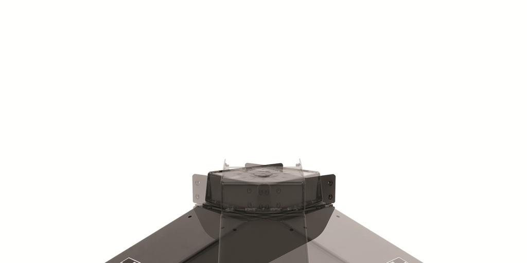
2 DEALER: (1) Provide this Manual to end user END USER: (1) Read and follow this Manual every time you use Sidewinder. (2) Save this Manual for Future Reference. PIN BOX SHOWN ASSEMBLED Equipment Required: Wrenches: 15/16, 1 1/8 Drill Bits: Not Required White Lithium Grease, Torque Wrench (3) Pass on copies of Manual to any other users or owner. Do Not Exceed Lower of Towing Vehicle Manufacturer s Rating, Trailer Manufacturer s Rating or Max Gross Trailer WT (LB) Max Pin WT (LB) 16,000 LB 3,200 LB 1 Qty. (1) Upper Turret 2 Qty. (1) Wear Plate 1 3 Qty. (1) Revolution Arm 4 Qty. (1) Universal Wedge* 5 Qty. (1) Pivot Bushing 6 6 Qty. (2) 3/4 10 Hex Nut Qty. (2) 3/4 Conical Washer 8 Qty. (2) 3/4-10x2 Grade 5 Hex Bolt 8 9 Qty. (1) Bearing Cup 5 10 Qty. (1) Bearing Cone 3 11 Qty. (1) Shaft Washer 12 Qty. (1) 1/4 x 3 Cotter Pin 13 Qty. (1) 1 ½ - 12 Castle Hex Nut 14 Qty. (2) Bolt, 5/8-11 X 1 3/4 Grade 5 Hex Bolt w/ Nylon 15 Qty. (2) 5/8 Conical Washer INDEX 1. CLEARANCE CHECK & GUIDELINES FOR MATCHING TOW VEHICLE AND TRAILER P LOCK OUT BOLTS INSTRUCTIONS P WEDGE ADJUSTMENT/SELECTION P HOOK-UP & PULL TEST PROCEDURE P UNHOOKING P BEFORE EACH TRIP & MAINTENANCE P YEAR LIMITED WARRANTY P. 8 4* 15 Figure Failure to follow all of these instructions may result in death or serious injury!
3 Figure 2 Measure Distance A : From Center of Revolution pivot to farthest point on coach front cap. Measure Distance X : From King Pin to the rear of the truck cab. If Distance X + 24 is Greater Than Distance A Towing up to 90º or More is possible. GUIDELINES FOR MATCHING TOW VEHICLE AND TRAILER Figure 3 CAUTION: A minimum clearance between the bumper and trailer (Measured at the same height) of 2 ft. is recommended. Due to Vehicle and RV Trailer variations; it is necessary to check this clearance. If the clearance is less than the minimum, this can be done after installation by making a slow turn, in a controlled driving environment (i.e. closed parking lot, grass field, etc.) with the aid of an observer to watch for interference. 1. The Height of the hitch and pin box should be adjusted so the trailer is approximately level as it is towed. Allow approximately 6 in. clearance between the top of the bed and the underside of the front of the trailer for pitch and yaw of the trailer (See Figure 4). For off-road use allow more clearance between pickup walls and trailer. Figure 4
4 CAUTION: The Measurements in figures 2, 3 & 4 are guidelines, If your measurements are close to these numbers, re-check clearances. If vehicle and/or trailer has any added bed vanity accessories (i.e. fairings, air dams, ground effects, bed rails, etc.) additional dimensioning and clearance checks have to be made. CPP is not responsible for damage incurred due to disregarding these clearance checks. Check Compatibility of Your 5 th Wheel Hitch With The Revolution. Refer to the specific product page for the Revolution up to date 5 th Wheel Hitch Compatibility. Avoid putting any part of your body under the trailer or between the truck and trailer. Unexpected or accidental movement of the truck or the trailer can cause serious injury or death If you must place any part of your body under the trailer or between the truck and trailer you MUST perform ALL of the following steps: Check that the truck transmission is in park Check that the emergency brake is set Block in front of and behind all trailer tires Check that the trailer landing gear are resting on firm ground Conventional Transport: The Revolution Pin-Box is very versatile and can be used as a standard pin box Conventional Transport. For conventional transport (2) ¾ GR 5 Bolts and Hardware are installed in the back of the unit (figure 5), on OE applications these come installed from the factory and may or may not have been removed by the dealer. The two bolts prevent rotation and allow use of the pin-box without the wedge installed. Lock-Out Bolts Revolution Transport: Figure 5 Revolution Pin-Boxes equipped with lock-out bolts can be converted to activate the Revolution feature. This feature moves the pivot from the truck bed to the pin-box mounting wings under the nose of the trailer and allows worry free towing up to 90º or more.

5 DANGER: Do Not install a wedge without removing the Lock-Out Bolts. Never operate without a wedge if the Lock-Out bolts are not installed. Doing this will create a double pivot and could result in death or serious injury and/or damage to the tow vehicle and trailer. Activating the Revolution Feature: 1. Remove (2) ¾ Lock-Out bolts and hardware from the rear of the pin-box (figure 5). You can store them in the holes pointed to. (figure 6) 2. Remove the universal wedge from it s storage location by removing (2) 5/8-11 X 1 3/4 bolts and lock washers. Note: The universal wedge is supplied with the unit and provides a lockout for many different fifth wheel hitches. Cequent Performance Products offers custom wedges designed for specific fifth wheel hitches, If a custom wedge is available for your hitch application, CPP recommends replacing the universal wedge with a custom wedge to provide the best fit for your hitch. The universal wedge should remain with the unit as it may be necessary if breakdown occurs to fit a tow vehicle other than your own. Lock Out Bolt Storage Location Wedge In Storage Location Figure 6 Wedge In Position for Sidewinder TM Feature Activation Figure 7 Before installing the universal wedge in position it is necessary to decide the best orientation for your hitch application. This can be done by referencing the diagrams below. Orientation for Reese/Draw-Tite/Hidden Hitch Select Series, Pro Series, Husky & similar style fifth wheel heads. Orientation for Reese/Draw-Tite/Hidden Hitch Signature Series & Select Plus, Reese Titan 16K & 20K, B&W and similar style fifth wheels. Relief Must Face Down for these applications in order to clear the jaw. Figure 8 Figure 9
6 Activating the Revolution Feature Con t: 3. Install the universal wedge into the position for Revolution feature activation (figure 7), in the proper orientation for your fifth wheel. The bolts will not be fully tightened at this time. (figure 10) Only tighten the (2) 5/8-11 X 1 3/4 wedge bolts until the lock washers begin to engage. The wedge should be allowed to slide with the rap of a hammer or mallet. 4. Apply grease to the surface on both sides of the wedge, the back side of the pin, and the skid plate surface as shown in figure 10. *For all Fifth Wheel Heads, lubricate the area where the jaw passes under the wedge. Apply grease to surface on both sides of the wedge. Apply grease to skid plate surface for hook-up and un-hook. Figure 10 *Lubricate the area where the jaw passes under the wedge Grease around the pin. 5. Hook-up to the fifth wheel trailer following the hook-up procedure in this manual, for proper latching of the fifth wheel hitch refer to the owners manual for your fifth wheel hitch. 6. With the trailer wheels still firmly blocked, landing gear still resting firm on the ground and supporting the trailer weight, and truck stationary and in park with the emergency brake on: Tap the wedge firmly forward until it will no longer travel. Look to see that the wedge is contacting both side of the funnel area of the hitch. If not is may be necessary to pull trailer forward slightly with the trailer brakes applied to straighten truck hitch and pin box. 7. Attempt to tighten both wedge bolts. Both bolts may not be accessible while the unit is hitched, in these cases tighten the most accessible bolt (usually the rear); these bolts will later be tightened to the proper torque value. 8. Unhook the trailer from the tow vehicle following the unhooking procedure in this manual. 9. Torque (2) 5/8 Wedge Bolts to 150 ft-lbs (figure 11). A thin walled socket may be necessary. 10. The wedge adjustment is a one time adjustment for your fifth wheel hitch. If a different fifth wheel hitch is used after this adjustment, it is necessary to readjust the wedge for the specific fifth wheel hitch. Torque (2) 5/8 Wedge Bolts to 150 ft-lbs. Figure 11
7 HOOK-UP PROCEDURE: IMPORTANT: Operating Instructions YOU ARE RESPONSIBLE FOR SAFE HITCHING AND UNHITCHING OPERATIONS. DO NOT RELY ON OTHERS TO PERFORM THESE DUTIES. YOU MUST PERSONALLY MAKE SURE THE FOLLOWING STEPS ARE PERFORMED IN THE FOLLOWING ORDER! FAILURE TO FOLLOW THESE INSTRUCTIONS MAY RESULT IN DEATH OR SERIOUS INJURY. 1. Place blocks (sometimes called chocks ) firmly against front and rear of each trailer wheel to prevent any possible forward or rearward motion. DO NOT REMOVE BLOCKS UNTIL EACH OF THE FOLLOWING STEPS AND THE PULL TEST HAVE BEEN COMPLETED. Lower tailgate if necessary. Clearance of the lowered tailgate to the trailer needs to be monitored during hookups as some manufacturer combinations of truck and trailer have little or no clearance. 2. Using trailer jacks, adjust trailer height following the directions in the trailer manual so that bottom of trailer pin box ( A in Figure 12) is ½ to 1 inch below skid plate (See B in Figure 12). During the hitching maneuver, the bottom of the trailer pin box should come in contact with skid plate ramp ( C in Figure 12). Hitch Skid Plate (B) Figure 12 CORRECT Bottom of Pin Box (A) Skid Plate Ramp (C) Bottom of Pin Box (A) 1/2 To 1 Inch Below Hitch Skid Plate (B) Bottom of Pin Box Above Hitch Skid Plate Figure 13 WRONG Failure to follow this instruction may result in king pin being too high and coming to rest on top of closed jaws or not completely inside jaw. This could result in trailer separating from hitch. Trailer separation may result in death or serious injury if anyone is under the trailer or between truck and trailer when separation occurs. 3. Follow your hitch manufactures instructions for safe hook-up. PULL TEST Failure to perform pull test may result in death or serious injury 1. With all trailer wheels still firmly blocked, and 2. Trailer landing gear still resting on firm ground and supporting trailer weight and, 3. Truck stationary and with emergency brake on: 4. Make sure no one is between truck and trailer, Return to cab of truck and release truck s emergency brake. Apply trailer brakes. Try to pull trailer slowly forward with the truck. If the trailer is properly hitched, the wheel blocks and trailer brakes should keep the truck from moving forward. NOTE: If trailer is not properly hitched, trailer will separate from hitch and truck will move forward leaving trailer behind. If you followed all previous steps, the trailer will not drop or fall. Failure to keep wheels blocked and landing gear down could result in trailer suddenly moving or falling. This could result in death or serious injury! 5. After successfully performing above steps, fully raise trailer landing gear (see trailer manual). 6. Check and inspect all electrical circuits for proper operation. (Clearance lights, turn signals, stop lights, etc.). 7. Remove and store all trailer wheel blocks.
8 UNHOOKING PROCEDURE Operating Instructions PERFORM THE FOLLOWING IN THIS ORDER: 1. Make sure truck is in park with emergency brake on. 2. Place blocks firmly against front and rear of each trailer wheel to prevent any possible forward or rearward motion. 3. Using trailer jacks, lower trailer landing gear following the directions in the Trailer Manual until feet of landing gear are resting on firm ground. Trailers that are not stable or properly hitched can fall and cause death or serious injury! To avoid death or serious injury: All trailer tires MUST be blocked in front and behind each tire AND Trailer landing gear MUST be resting on firm ground AND Truck MUST be stationary, in park, with emergency brake on! 4. Lower truck tail gate. 5. Disconnect power cable and breakaway switch cable between truck and trailer. 6. Remove bail pin from hole in handle. 7. Pull hitch handle out completely until it latches in open position so that king pin is no longer securely grasped by hitch jaws. Trailer is now free from hitch and truck. If handle does not pull out, there is probably pressure against the jaw. To relieve this pressure, back the truck slightly. Reset truck emergency brake. Then pull hitch handle out completely until it latches in open position. 8. AFTER MAKING CERTAIN NO ONE IS STANDING BETWEEN TRUCK AND TRAILER OR IN FRONT OF TRUCK, drive truck slowly away from trailer. WARNING Whenever possible, avoid putting body under trailer or between truck and trailer If you need to place any part of our body under trailer or between truck and trailer: All trailer tires MUST be blocked in front and behind each tire AND Trailer landing gear MUST be resting on firm ground AND Truck MUST be stationary, in park, with emergency brake on! 9. KEEP WHEEL BLOCKS IN PLACE. This will keep trailer from moving unexpectedly
9 Part Number Purchased: Place of Purchase: Date of Purchase: Part Manufactured Date (located on driver-side sticker): BEFORE EACH TRIP: 1. CHECK YOUR EQUIPMENT: Check the condition of all of your towing equipment and keep it in top condition.. 2. Check to see that all bolts are properly tightened. 3. Check wedge engagement in the fifth wheel jaw, refer to wedge adjustment portion of this manual. MAINTENANCE: 1. To help with hookup and for product longevity: frequently lubricate the wedge surfaces, around the king pin, and the skid plate surface, apply a lithium grease to the bearing surfaces as described in the assembly section of this manual. (Note: Resistance is typical in the Sidewinder arm) 2. Keep pin-box hitch painted to prevent rust and maintain a good appearance. (Do Not paint over labels) 3. At least once per season, disassemble unit to clean, inspect, lubricate and re-torque fasteners. When reassembling, use lithium grease on the wear plate and bushing. Tighten large nut to a minimum of 80 ft. lbs. and then tighten to the nearest thru hole for cotter pin installation.
16K Reese Revolution. Operating Instructions
 Operating Instructions Operating Instructions DEALER: (1) Provide this Manual to end user END USER: (1) Read and follow this Manual every time you use Sidewinder. (2) Save this Manual for Future Reference.
Installation Instructions
 PIN BOX SHOWN ASSEMBLED Equipment Required: Fastener Kit: ST100F Wrenches: 15/16, 1 1/8 Drill Bits: Not Required White Lithium Grease, Torque Wrench Installation Instructions DEALER/INSTALLER: (1) Provide
Installation Instructions
 PIN BOX SHOWN ASSEMBLED Equipment Required: Fastener Kit: ST100F Wrenches: 15/16, 1 1/8 Drill Bits: Not Required White Lithium Grease, Torque Wrench Installation Instructions DEALER/INSTALLER: (1) Provide
Installation Instructions
 PIN BOX SHOWN ASSEMBLED Equipment Required: Wrenches: 15/16, 3/4, 9/16 & TORQUE WRENCH Installation Instructions 5 th Airborne Sidewinder DEALER/INSTALLER: (1) Provide this Manual to end user END USER:
Installation Instructions
 Sidewinder Turret TM Part Number: 61300 DEALER/INSTALLER: (1) Provide this Manual to end user END USER: (1) Read and follow this Manual for Sidewinder Turret Installation. (2) Save this Manual for Future
16K Revolution Service Kit Instructions 86016
 86016 Equipment Required: Wrenches: 15/16, 1 1/8, Torque Wrench, Rubber Mallet Included Service Kit Items: 1 Qty. (1) Wear Plate 2 Qty. (1) Pivot Bushing 3 Qty. (1) Bearing Cup 4 Qty. (1) Bearing 1 5 Qty.
5 th Airborne Sidewinder Service Kit Instructions 94316
 94316 Equipment Required: Wrenches: 15/16, Torque Wrench, Rubber Mallet 3 4 5 2 Included Service Kit Items: 1 Qty. (1) Wear Plate 2 Qty. (1) Wear Bushing 3 Qty. (1) Wear Disc 4 Qty. (4) 5/8-11x2 GRD8 Bolt
Turning Point Pin Box. by Trailair OWNER'S MANUAL
 Turning Point Pin Box by Trailair OWNER'S MANUAL TABLE OF CONTENTS Product and Safety Information 2 Preparation 3 Tow Rating Weights Check 3 Cab and Bed Clearance Check 3 Operation 3 Conventional Transport
INSTALLATION / OPERATING INSTRUCTIONS Reese Elite Series FIFTH WHEEL SLIDER HITCH
 INSTALLATION / OPERATING INSTRUCTIONS Reese Elite Series FIFTH WHEEL SLIDER HITCH DEALER/INSTALLER: (1) Provide this Manual to end user. (2) Physically demonstrate hitching and unhitching procedures in
INSTRUCTION MANUAL R16 - Fifth Wheel Hitch
 You can take it with you. INSTRUCTION MANUAL R16 - Fifth Wheel Hitch Product No. 30866 DEALER/INSTALLER: END USER: (1) Provide this Manual to end user. (2) Physically demonstrate hitching and unhitching
INSTRUCTION MANUAL 16K - Fifth Wheel Hitch
 You can take it with you. INSTRUCTION MANUAL 16K - Fifth Wheel Hitch Product No. 30047 DEALER/INSTALLER: END USER: (1) Provide this Manual to end user. (2) Physically demonstrate hitching and unhitching
16K ORBITAL ROTATING RUBBER PIN BOX *
 16K ORBITAL ROTATING RUBBER PIN BOX * OPERATING INSTRUCTIONS AND OWNER S MANUAL * Patented Congratulations on the purchase of the MORryde 16k Orbital Rotating Rubber Pin Box. This revolutionary new system
INSTRUCTION MANUAL TITAN 16K - Fifth Wheel Hitch Plymouth MI
 You can take it with you. INSTRUCTION MANUAL TITAN 16K - Fifth Wheel Hitch Plymouth MI Product No. 30866 DEALER/INSTALLER: END USER: (1) Provide this Manual to end user. (2) Physically demonstrate hitching
INSTRUCTION MANUAL 22K - Fifth Wheel Hitch
 You can take it with you. INSTRUCTION MANUAL 22K - Fifth Wheel Hitch Product No. 30033 DEALER/INSTALLER: (1) Provide this Manual to end user. (2) Physically demonstrate hitching and unhitching procedures
INSTRUCTION MANUAL 16K - Fifth Wheel Hitch
 You can take it with you. INSTRUCTION MANUAL 16K - Fifth Wheel Hitch Product No. 30047 DEALER/INSTALLER: END USER: (1) Provide this Manual to end user. (2) Physically demonstrate hitching and unhitching
R20 - Fifth Wheel Hitch
 You can take it with you. INSTRUCTION MANUAL R20 - Fifth Wheel Hitch Plymouth MI Product No. 30867 DEALER/INSTALLER: END USER: (1) Provide this Manual to end user. (2) Physically demonstrate hitching and
16K and 19K Sidewinder TM Service Kit Instructions 86005
 86005 Equipment Required: Wrenches: 15/16, 1 1/8, Torque Wrench, Rubber Mallet Included Service Kit Items: 1 Qty. (1) Wear Plate 2 Qty. (6) 5/8 Conical Washer 3 Qty. (2) Wedge Bolt, 5/8-11 X 1 3/4 GRD
Turning Point Pin Box. by Trailair OWNER'S MANUAL
 Turning Point Pin Box by Trailair OWNER'S MANUAL TABLE OF CONTENTS Product and Safety Information 2 Preparation 3 Tow Rating Weights Check For 10,000 lbs Pin Box (Fig. 1) 3 Tow Rating Weights Check For
20K - Fifth Wheel Hitch
 You can take it with you. INSTRUCTION & OPERATION MANUAL 20K - Fifth Wheel Hitch DEALER/INSTALLER: (1) Provide this Manual to end user. (2) Physically demonstrate hitching and unhitching procedures in
Instruction Manual 15K - Fifth Wheel Hitch Part Number 6030 & 6031
 DEALER/INSTALLER: (1) Provide this Manual to end user. (2) Physically demonstrate hitching and unhitching procedures in this Manual to end user. (3) Have end user demonstrate that he/she understands procedures.
Instruction Manual 30K - Fifth Wheel Hitch Part Number 30054
 You can take it with you. ELKHART, IN., OAKVILLE, ONT. Instruction Manual 30K - Fifth Wheel Hitch Part Number 30054 DEALER/INSTALLER: (1) Provide this Manual to end user. (2) Physically demonstrate hitching
OPERATING INSTRUCTIONS. Elite Series 18K & 25K 5TH WHEEL HITCH END USER: For Installation Assistance or Technical Help, Call
 OPERATING INSTRUCTIONS Elite Series 18K & 25K 5TH WHEEL HITCH DEALER/INSTALLER: (1) Provide this Manual to end user. (2) Physically demonstrate hitching and unhitching procedures in this Manual to end
INSTALLATION / OPERATING INSTRUCTIONS Reese Elite Series FIFTH WHEEL SLIDER HITCH
 INSTALLATION / OPERATING INSTRUCTIONS Reese Elite Series FIFTH WHEEL SLIDER HITCH DEALER/INSTALLER: (1) Provide this Manual to end user. (2) Physically demonstrate hitching and unhitching procedures in
Installation / Owners Manual
 DEALER/INSTALLER: (1) Provide this Manual to end user END USER: Part Number: 94621 94622* *Packaged for Individual sale. (1) Read and follow this Manual for Reese Installation. (2) Save this Manual for
Model 3770 WARNING. Failure to comply with the safety information in these instructions could result in serious injury or death.
 B&W Trailer Hitches 1216 Hawaii Road / PO Box 186 Humboldt, KS 66748 P:620.473.3664 See Limited Lifetime Warranty at F:620.869.9031 bwtrailerhitches.com/warranty NOTE: We recommend reading instructions
B&W Trailer Hitches 1216 Hawaii Road / PO Box 186 Humboldt, KS P: F:
 B&W Trailer Hitches 1216 Hawaii Road / PO Box 186 Humboldt, KS 66748 P:620.473.3664 F:620.473.3766 NOTE: We recommend reading instructions before beginning the installation. GM OEM Mount System Slider
B&W Trailer Hitches 1216 Hawaii Road / PO Box 186 Humboldt, KS P: F:
 B&W Trailer Hitches 1216 Hawaii Road / PO Box 186 Humboldt, KS 66748 P:620.473.3664 F:620.869.9031 NOTE: We recommend reading instructions before beginning the installation. Ford OEM Mount System Slider
OPERATING INSTRUCTIONS. Elite Series 18K & 25K 5TH WHEEL HITCH END USER:
 OPERATING INSTRUCTIONS Elite Series 18K & 25K 5TH WHEEL HITCH DEALER/INSTALLER: (1) Provide this Manual to end user. (2) Physically demonstrate hitching and unhitching procedures in this Manual to end
B&W Trailer Hitches 1216 Hawaii Road / PO Box 186 Humboldt, KS P: F: " Split Lock Washers 8
 B&W Trailer Hitches 1216 Hawaii Road / PO Box 186 Humboldt, KS 66748 P:620.473.3664 F:620.869.9031 NOTE: We recommend reading instructions before beginning the installation. Companion Slider Hitch Installation
Model 3400 ATTENTION: WARNING
 B&W Trailer Hitches 1216 Hawaii Road / PO Box 186 Humboldt, KS 66748 P:620.473.3664 F:620.473.3766 NOTE: We recommend reading instructions before beginning the installation. Companion Slider Hitch Installation
<THESE INSTRUCTIONS MUST BE GIVEN TO THE END USER> B&W Trailer Hitches 1216 Hawaii Road / PO Box 186 Humboldt, KS P: F:
 B&W Trailer Hitches 26 Hawaii Road / PO Box 86 Humboldt, KS 66748 P:620.473.3664 F:620.869.903 Ford OEM Mount System Installation Instructions 20,000
<THESE INSTRUCTIONS MUST BE GIVEN TO THE END USER> B&W
 B&W Trailer Hitches 26 Hawaii Road / PO Box 86 Humboldt, KS 6678 P:620.73.366 F:620.869.903 GM Puck Mount System Installation Instructions 20,000 LBS.
<THESE INSTRUCTIONS MUST BE GIVEN TO THE END USER> 1 2 " X 1 1 2" Hex Cap Screws " Split Lock Washers " Threaded block 4
 B&W Trailer Hitches 1216 Hawaii Rd / PO Box 186 Humboldt, KS 66748 P:620.473.3664 F:620.473.3766 Companion Hitch Installation Instructions 20,000 LBS.
<THESE INSTRUCTIONS MUST BE GIVEN TO THE END USER> B&W Trailer Hitches 1216 Hawaii Road / PO Box 186 Humboldt, KS P: F:
 B&W Trailer Hitches 26 Hawaii Road / PO Box 86 Humboldt, KS 6678 P:620.73.366 F:620.869.903 Ford OEM Mount System Installation Instructions 20,000 LBS.
Installation Instructions READ THOROUGHLY BEFORE BEGINNING Signature Series Rail Kit Dodge Ram Trucks-all, including Mega-cabs
 INDEX Failure to follow all of these instructions may result in death or serious injury!. GUIDELINES FOR MATCHING TOW VEHICLE AND TRAILER. Pages -. DRILLED AND BOLTED INSTALLATION FIGURE. Page 4. NO-DRILL,
Installation / Owners Manual
 DEALER/INSTALLER: (1) Provide this Manual to end user END USER: Part Number: 94621 94622* *Packaged for Individual sale. (1) Read and follow this Manual for Reese Installation. (2) Save this Manual for
20K - Fifth Wheel Hitch
 You can take it with you. INSTRUCTION & OPERATION MANUAL 20K - Fifth Wheel Hitch DEALER/INSTALLER: (1) Provide this Manual to end user. (2) Physically demonstrate hitching and unhitching procedures in
<THESE INSTRUCTIONS MUST BE GIVEN TO THE END USER> B&W Trailer Hitches 1216 Hawaii Road / PO Box 186 Humboldt, KS P: F:
 B&W Trailer Hitches 26 Hawaii Road / PO Box 86 Humboldt, KS 6678 P:620.73.366 F:620.869.903 RAM OEM Mount System Installation Instructions 25,000 LBS.
<THESE INSTRUCTIONS MUST BE GIVEN TO THE END USER> BASE BOLT BAG (RVB3500) ITEM DESCRIPTION QTY. 1 2 " X 1 1 2" Hex Cap Screws 16
 ITEM DESCRIPTION QTY. 1 2 X 1 1 2 Hex Cap Screws 16") B&W Trailer Hitches 1216 Hawaii Rd / PO Box 186 Humboldt, KS 66748 P:620.473.3664 F:620.869.9031 Companion Hitch Installation Instructions 20,000 LBS.
B&W Trailer Hitches 1216 Hawaii Rd / PO Box 186 Humboldt, KS 66748 P:620.473.3664 F:620.869.9031 Companion Hitch Installation Instructions 20,000 LBS.
INSTRUCTION MANUAL 16K - Fifth Wheel Hitch
 You can take it with you. INSTRUCTION MANUAL 16K - Fifth Wheel Hitch Plymouth MI Product No. 30047 DEALER/INSTALLER: END USER: (1) Provide this Manual to end user. (2) Physically demonstrate hitching and
INSTALLATION INSTRUCTIONS MOUNTING KIT COMMERCIAL TRUCK FOR 34 OUTSIDE FRAME WIDTH ONLY. Front of vehicle
 INSTALLATION INSTRUCTIONS MOUNTING KIT COMMERCIAL TRUCK FOR 34 OUTSIDE FRAME WIDTH ONLY DEALER/INSTALLER: (1) Provide this Manual to end user. END USER: (1) Save this Manual for future reference. (2) Pass
ASSEMBLY INSTRUCTIONS Reese Elite Series FIFTH WHEEL SLIDER HITCH
 ASSEMBLY INSTRUCTIONS Reese Elite Series FIFTH WHEEL SLIDER HITCH DEALER/INSTALLER: (1) Provide this Manual to end user. (2) Physically demonstrate procedures in this Manual to end user. (3) Have end user
Installation Instructions
 Part Numbers: ALL 5AB-XXXX DEALER/INSTALLER: (1) Provide this Manual to end user END USER: (1) Read and follow this Manual every time you use this product. PIN BOX SHOWN ASSEMBLED Equipment Required: Wrenches:
INSTALLATION INSTRUCTIONS MOUNTING KIT GENERAL MOTORS Chevrolet Silverado Sierra, GMC 3500HD; Silverado
 INSTALLATION INSTRUCTIONS MOUNTING KIT GENERAL MOTORS 2001-04 Chevrolet Silverado Sierra, GMC 3500HD; 99-2000 Silverado DEALER/INSTALLER: (1) Provide this Manual to end user. END USER: (1) Save this Manual
INSTALLATION INSTRUCTIONS MOUNTING KIT GENERAL MOTORS 88-98; Classic; 1500/2500/3500 (6 and 8 BEDS)
") DEALER/INSTALLER: (1) Provide this Manual to end user. INSTALLATION INSTRUCTIONS MOUNTING KIT GENERAL MOTORS 88-98; 99 2000 Classic; 1500/2500/3500 (6 and 8 BEDS) END USER: (1) Save this Manual for future
DEALER/INSTALLER: (1) Provide this Manual to end user. INSTALLATION INSTRUCTIONS MOUNTING KIT GENERAL MOTORS 88-98; 99 2000 Classic; 1500/2500/3500 (6 and 8 BEDS) END USER: (1) Save this Manual for future
BXR6200 Super Ride 20K 5 th Wheel Hitch
 Super Ride 20K 5 th Wheel Hitch Please read these in their entirety prior to installing or operating this equipment. This hitch is rated to 20,000 lbs. Gross Towing Weight and 5,000 lbs. Tongue Weight!
INSTALLATION INSTRUCTIONS MOUNTING KIT GENERAL MOTORS Chevrolet Silverado/GMC Sierra 2500HD & 3500HD
 INSTALLATION INSTRUCTIONS MOUNTING KIT GENERAL MOTORS 2001-2006 Chevrolet Silverado/GMC Sierra 2500HD & 3500HD DEALER/INSTALLER: (1) Provide this Manual to end user. END USER: (1) Save this Manual for
2/18 HJ26076 Rev 7 1
 1 2/18 HJ26076 Rev 7 Introduction Thank you for purchasing a Demco Hijacker hitch. We feel you have made a wise choice and hope you are completely satisfied with your new piece of equipment. WARRANTY POLICY,
Hi-Rise 18K 5TH WHEEL CONVERSION HITCH
 ASSEMBLY INSTRUCTIONS Hi-Rise 18K 5TH WHEEL CONVERSION HITCH DEALER/INSTALLER: (1) Provide this Manual to end user. END USER: (1) Read and follow this Manual every time you use Hitch. (2) Save this Manual
5 th Wheel Air Ride Connect and Uncoupling Procedure
 5 th Wheel Air Ride Connect and Uncoupling Procedure East Coast Partners Grp 1041 Old Blush Road., Suite 200 Celebration, FL 34747 Phone 321-939-2132 / Fax 866-201-3391 sales@airsafehitches.com www.airsafehitches.com
INSTALLATION INSTRUCTIONS MOUNTING KIT Toyota Tundra 8 BEDS
 DEALER/INSTALLER: INSTALLATION INSTRUCTIONS MOUNTING KIT Toyota Tundra 8 BEDS (1) Provide this Manual to end user. (2) Physically demonstrate procedures in this Manual to end user. (3) Have end user demonstrate
INSTRUCTION MANUAL Kwik Slide
 INSTRUCTION MANUAL Kwik Slide FOR USE WITH 30048 DEALER/INSTALLER: (1) Provide this Manual to end user. (2) Physically demonstrate sliding procedures in this Manual to end user. (3) Have end user demonstrate
INSTALLATION INSTRUCTIONS MOUNTING KIT 2010-CURRENT Dodge 2500 & 3500
 INSTALLATION INSTRUCTIONS MOUNTING KIT 2010-CURRENT Dodge 2500 & 3500 DEALER/INSTALLER: (1) Read all instructions before installation (2) Provide this Manual to end user. END USER: (1) Save this Manual
INSTALLATION INSTRUCTIONS MOUNTING KIT FOR ELITE SERIES
 INSTALLATION INSTRUCTIONS MOUNTING KIT FOR ELITE SERIES DO NOT EXCEED VEHICLE MANUFACTURER S RATING FOR 5th WHEEL TOWING OR MAXIMUM GROSS TRAILER WEIGHT OF 18,000lb. / 8160kg. DEALER/INSTALLER: (1) Provide
Page 1. 2/18 HJ26180 Rev 3
 Page 1 2/18 HJ26180 Rev 3 Introduction Thank you for purchasing a Demco Recon hitch. We feel you have made a wise choice and hope you are completely satisfied with your new piece of equipment. Please consult
Page 1. 11/17 HJ26201 Rev 1
 Page 1 11/17 HJ26201 Rev 1 Thank you for purchasing a Demco Recon hitch. We feel you have made a wise choice and hope you are completely satisfied with your new piece of equipment. Unless otherwise specified,
INSTALLATION INSTRUCTIONS MOUNTING KIT FOR ELITE SERIES
 INSTALLATION INSTRUCTIONS MOUNTING KIT FOR ELITE SERIES DEALER/INSTALLER: (1) Provide this Manual to end user. END USER: (1) Save this Manual for future reference. (2) Pass on copies of Manual to any other
BXR6200 Super Ride 20K 5 th Wheel Hitch
 Super Ride 20K 5 th Wheel Hitch Please read these in their entirety prior to installing or operating this equipment. Serial Number This hitch is rated to 20,000 lbs. Gross Towing Weight and 5,000 lbs.
Pro Series. INSTRUCTION MANUAL 15K Fifth Wheel Hitch
 Pro Series INSTRUCTION MANUAL 15K Fifth Wheel Hitch DEALER/INSTALLER: (1) Provide this Manual to end user. (2) Physically demonstrate hitching and unhitching procedures in this Manual to end user. (3)
THE GLIDER 5th Wheel Attachment
 April 2007 APPLICATION: INSTALLATION INSTRUCTIONS MODEL NO. 70460 70046 THE GLIDER 5th Wheel Attachment For use on short bed pickup applications US Patent No. 6247720 COMPLETE PARTS LIST Part Description
ASSEMBLY INSTRUCTIONS Signature Series Gooseneck
 ASSEMBLY INSTRUCTIONS Signature Series Gooseneck DEALER/INSTALLER: (1) Provide this Manual to end user. (2) Physically demonstrate procedures in this Manual to end user. (3) Have end user demonstrate that
Installation Instructions
 Equipment Required: Wrenches: 9/16, 3/4, 1-1/8 Drill Bits: 11/32 Torque Wrench capable of reading 260 ft-lbs. Installation Instructions IN DEALERS: Please give these instructions to your customer. Do Not
BXR7200 Super Ride 20K 5 th Wheel Hitch
 BXR7200 Super Ride 20K 5 th Wheel Hitch Please read these in their entirety prior to installing or operating this equipment. This hitch is rated to 20,000 lbs. Gross Towing Weight and 5,000 lbs. Tongue
PAGE 1. 7/18 HJ26141 Rev 12
 PAGE 1 7/18 HJ26141 Rev 12 WARRANTY POLICY, OPERATOR MANUALS & REGISTRATION Go online to www.demco-products.com to review Demco warranty policies, operator manuals and register your Demco product. Please
Signature Series 24K 5 TH WHEEL HITCH
 ASSEMBLY INSTRUCTIONS Signature Series 24K 5 TH WHEEL HITCH DEALER/INSTALLER: (1) Provide this Manual to end user. END USER: (1) Read and follow this Manual every time you use Hitch. (2) Save this Manual
K Autoslide. HJ26141, Rev 13 12/18
 5th wheel hitch 6141 13K Autoslide HJ26141, Rev 13 12/18 INTRODUCTION WARRANTY POLICY, OPERATOR MANUALS, PARTS MANUALS & REGISTRATION Go online to www.demco-products.com to review Demco warranty policies,
INSTALLATION INSTRUCTIONS
 INSTALLATION INSTRUCTIONS WARNING: NEVER EXCEED YOUR VEHICLE MANUFACTURER'S RECOMMENDED TOWING CAPACITY A20 5TH WHEEL HITCH TABLE OF CONTENTS Page# Description 1 Warnings & Precautions 2 - Assembly & Installation
INSTRUCTION MANUAL 15K Fifth Wheel Hitch
 INSTRUCTION MANUAL 15K Fifth Wheel Hitch DEALER/INSTALLER: (1) Provide this Manual to end user. (2) Physically demonstrate hitching and unhitching procedures in this Manual to end user. (3) Have end user
K Autoslide & K Autoslide
 HJ26077, Rev 16 07/18 5th wheel hitch 6077 18K Autoslide & 6107 21K Autoslide US Pat. 7,506,886 US Pat. 7,753,392 CA Pat. 2,576,427 AS Pat. 2007200421 Important Information WARRANTY POLICY, OPERATOR MANUALS
6/17 HJ26077 Rev 12. US Pat. 7,506,886 US Pat. 7,753,392 CA Pat. 2,576,427 AS Pat PAGE 1
 6/17 HJ26077 Rev 12 US Pat. 7,506,886 US Pat. 7,753,392 CA Pat. 2,576,427 AS Pat. 2007200421 PAGE 1 WARRANTY POLICY, OPERATOR MANUALS & REGISTRATION Go online to www.demco-products.com to review Demco
BXR6200 Super Ride 20K 5 th Wheel Hitch
 Super Ride 20K 5 th Wheel Hitch Please read these in their entirety prior to installing or operating this equipment. Serial Number This hitch is rated to 20,000 lbs. Gross Towing Weight and 5,000 lbs.
7/18 HJ26077 Rev 16. US Pat. 7,506,886 US Pat. 7,753,392 CA Pat. 2,576,427 AS Pat PAGE 1
 7/18 HJ26077 Rev 16 US Pat. 7,506,886 US Pat. 7,753,392 CA Pat. 2,576,427 AS Pat. 2007200421 PAGE 1 WARRANTY POLICY, OPERATOR MANUALS & REGISTRATION Go online to www.demco-products.com to review Demco
INSTALLATION, OPERATION & MAINTENANCE INSTRUCTIONS
 June 2004 INSTALLATION, OPERATION & MAINTENANCE INSTRUCTIONS Please be sure that this document is given to the end user of this product. It contains many important items relating to the proper usage of
BXR5203 RBW Li l Rocker & X-16 Curt E16 Installation Instructions. PinLock. Serial Number
 RBW Li l Rocker & X-16 Curt E16 Serial Number PinLock The act of uncoupling your fifth wheel trailer can be one of the most dangerous tasks performed when RVing. Accidents can cause broken bones, severed
COMPANION SLIDER YOUR TOWING ADVENTURE BEGINS
 COMPANION SLIDER YOUR TOWING ADVENTURE BEGINS DON'T WORRY YOUR HITCH WAS MADE RIGHT HERE. You ve got a lot riding on your hitch and the only thing keeping your truck and your trailer connected are those
BXR7200 Super Ride 20K 5 th Wheel Hitch
 BXR7200 Super Ride 20K 5 th Wheel Hitch Please read these in their entirety prior to installing or operating this equipment. Serial Number This hitch is rated to 20,000 lbs. Gross Towing Weight and 5,000
INSTALLATION INSTRUCTIONS
 INSTALLATION INSTRUCTIONS WARNING: NEVER EXCEED YOUR VEHICLE MANUFACTURER'S RECOMMENDED TOWING CAPACITY Q24 5TH WHEEL HITCH TABLE OF CONTENTS Page# Description 1 Warnings & Precautions 2 Assembly & Installation
<THESE INSTRUCTIONS MUST BE GIVEN TO THE END USER> B&W Trailer Hitches 1216 Hawaii Rd / PO Box 186 Humboldt, KS P: F:
 B&W Trailer Hitches 26 Hawaii Rd / PO Box 86 Humboldt, KS 66748 P:620.473664 F:620.869.903 Turnoverball Gooseneck Hitch Installation Instructions Mounting
E5 5 th Wheel Hitch Assembly
 E5 5 th Wheel Hitch Assembly 1. Hitch Handle Assembly a) Rotate the handle shaft so the bolt hole is oriented at the top. b) Hold the handle with the grip pointed downward and slide the handle onto the
<THESE INSTRUCTIONS MUST BE GIVEN TO THE END USER> B&W
 B&W Trailer Hitches 6 Hawaii Rd / PO Box 86 Humboldt, KS 66748 P:60.473664 F:60.869.903 Turnoverball Gooseneck Hitch Installation Instructions MODEL 08
<THESE INSTRUCTIONS MUST BE GIVEN TO THE END USER> B&W
 B&W Trailer Hitches 1216 Hawaii Rd / PO Box 186 Humboldt, KS 66748 P:620.473664 F:620.869.9031 Turnoverball Gooseneck Hitch Installation Instructions
***Be sure that the loaded trailer weight does not exceed 24,000 lbs. or the vertical load rating does not exceed 6000 lbs.
 April 2006 INSTALLATION INSTRUCTIONS MODEL NO. 70680 07068 24K 5th Wheel with Heavy Duty EZ-ROLLER For use on shortbed P/U applications US Pat. No. 6247720 PARTS INCLUDE: 1. 1675-07 Head Assembly (1) 15.
Q5 5 th Wheel. Unpacking Assembly / Installation
 PA1 Unpacking Assembly / Installation Installer: Read and understand this manual. Fully instruct and demonstrate the operation of this 5 th Wheel Hitch to the End-User. Include the importance of observing
Installation Instructions
 Equipment Required: Fastener Kit: F Wrenches: 3/4, 15/16 Drill Bits: 1/4 Other Tools: Drill WARNING: Under no circumstances do we recommend exceeding the towing vehicle manufacturers recommended vehicle
COVER PAGE BASE RAIL MOUNTING KIT 10 BOLT RAIL KIT NOTE!
 COVER PAGE 30035 BASE RAIL MOUNTING KIT 10 BOLT RAIL KIT NOTE! If you have a newer model year truck you must go to one our websites for the most recent updated instructions. www.reeseproducts.com or www.draw-tite.com
<THESE INSTRUCTIONS MUST BE GIVEN TO THE END USER> B&W Trailer Hitches 1216 Hawaii Rd / PO Box 186 Humboldt, KS P: F:
 B&W Trailer Hitches 26 Hawaii Rd / PO Box 86 Humboldt, KS 66748 P:620.473664 F:620.473766 Turnoverball Gooseneck Hitch Installation Instructions Mounting
<THESE INSTRUCTIONS MUST BE GIVEN TO THE END USER> B&W
 B&W Trailer Hitches 6 Hawaii Rd / PO Box 86 Humboldt, KS 6678 P:60.7366 F:60.86.03 Turnoverball Gooseneck Hitch Installation Instructions MODEL 38 0 08
<THESE INSTRUCTIONS MUST BE GIVEN TO THE END USER> B&W
 B&W Trailer Hitches 1216 Hawaii Rd / PO Box 186 Humboldt, KS 66748 Turnoverball Gooseneck Hitch Installation Instructions MODEL 1314 2013 2014 RAM 3500
Installation Instructions
 GOOSENECK MOUNTING KIT Equipment Required: Fastener Kit: F Wrenches: 13mm, 3/4, 7/8, 15/16 Drill Bits: 1/4 Other Tools: Drill WARNING: Under no circumstances do we recommend exceeding the towing vehicle
OWNER S MANUAL. The following instructions provide valuable information regarding the function and proper use of the Super 5 th Wheel Towing System.
 OWNER S MANUAL #1900 Industry Standard Super 5 th (16K) #2100 Industry Standard Super 5 th (18K) Gross Trailer Weight (Maximum) Vertical Load Weight (Max. Pin Weight) 16,000 lbs. 4,000 lbs. Gross Trailer
SPRING MAX. TONGUE MAX. GROSS TRAILER BAR WEIGHT(LB) WEIGHT (LB)
 WEIGHT (LB)") INSTALLATION / OPERATION INSTRUCTIONS WEIGHT DISTRIBUTING HITCH SYSTEMS 7901, 7902, 7903, 7979 (DUAL SWAY CONTROL ATTACHMENT) 7901=600LB WDH KIT, 7902=800LB WDH KIT, 7903=1200LB WDH KIT, 7979=HEAD KIT
INSTALLATION / OPERATION INSTRUCTIONS WEIGHT DISTRIBUTING HITCH SYSTEMS 7901, 7902, 7903, 7979 (DUAL SWAY CONTROL ATTACHMENT) 7901=600LB WDH KIT, 7902=800LB WDH KIT, 7903=1200LB WDH KIT, 7979=HEAD KIT
Installation Instructions
 Equipment Required: Installation Instructions Fastener Kit: F Wrenches: 8mm, 13mm, 3/4, 15/16 Drill Bits: 1/4 Other Tools: Drill, Reciprocating Saw, File WARNING: Under no circumstances do we recommend
5-13 HJ25989 rev 1 1
 1 5-13 HJ25989 rev 1 Introduction Thank you for purchasing a Demco Hijacker hitch. We feel you have made a wise choice and hope you are completely satisfied with your new piece of equipment. 1. Unless
<THESE INSTRUCTIONS MUST BE GIVEN TO THE END USER> B&W Trailer Hitches 1216 Hawaii Rd / PO Box 186 Humboldt, KS P: F:
 B&W Trailer Hitches 6 Hawaii Rd / PO Box 86 Humboldt, KS 6678 P:60.7366 F:60.73766 Turnoverball Gooseneck Hitch Installation Instructions MODEL 38 0 06
3/14 HJ26077 Rev 1. US Pat. 7,506,886 US Pat. 7,753,392 CA Pat. 2,576,427 AS Pat
 3/14 HJ26077 Rev 1 US Pat. 7,506,886 US Pat. 7,753,392 CA Pat. 2,576,427 AS Pat. 2007200421 VERY IMPORTANT PLEASE READ CAREFULLY The Hijacker Autoslide fifth wheel hitch was designed for use with recreational
Installation Instructions M5 HEAD & CENTER SECTION Hitch Rated for 27,000 lbs, Max. Pin Weight 6,750 lbs
 FOR INSTALLATION WITH M5 MOUNTING LEGS Installation Instructions M5 Hitch Rated for 27,000 lbs, Max. Pin Weight 6,750 lbs WARNING: Under no circumstances do we recommend exceeding the towing vehicle manufacturers
<THESE INSTRUCTIONS MUST BE GIVEN TO THE END USER> B&W
 B&W Trailer Hitches 1216 Hawaii Rd / PO Box 186 Humboldt, KS 66748 P:620.473.3664 F:620.869.9031 Turnoverball Gooseneck Hitch Installation Instructions
INSTALLATION INSTRUCTIONS READ THOROUGHLY BEFORE BEGINNING
 Catalog No. 6320 INSTALLATION INSTRUCTIONS READ THOROUGHLY BEFORE BEGINNING 6320 RAIL KIT - 1988 through 2000 Chevrolet/GMC Pickup w/6 ft. bed, 1999 Chevrolet C/K LS and GMC Sierra Classic w/6 ft. bed
Assembly, Installation, Operation and Maintenance Instructions. Base Rail Bracket Kit. For updates see PRODUCT SUPPORT tab at
 Assembly, Installation, Operation and Maintenance Instructions P/N: 32831 Base Rail Kit For updates see PRODUCT SUPPORT tab at www.huskytow.com Provide a copy of these Instructions to the end user of this
Installation instructions
 Installation instructions warning: never exceed your vehicle manufacturer's recommended towing capacity Q16 5th wheel hitch Table of contents Page# Description 1 Warnings & Precautions 2 - Assembly & Installation