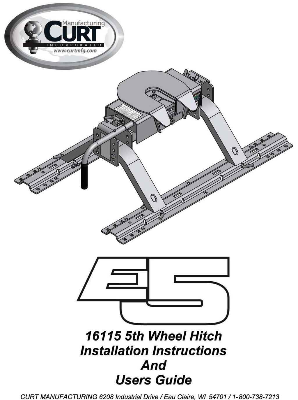
E5 5 th Wheel Hitch Assembly
|
|
|
- Horace Payne
- 5 years ago
- Views:
Transcription
1
2
3 E5 5 th Wheel Hitch Assembly 1. Hitch Handle Assembly a) Rotate the handle shaft so the bolt hole is oriented at the top. b) Hold the handle with the grip pointed downward and slide the handle onto the handle shaft. c) Fasten the hitch handle using the supplied bolt and nylock nut. 2. Hitch Assembly a) Attach the hitch handle to the hitch head. [See hitch handle assembly] b) Place the mounting rails [CM MRK] in the bed of the truck using the supplied installation instructions. c) Place the mounting channels into the mounting rails and secure using the ½ diameter clevis pins [CM RMP]. Secure the clevis pins using the large hairpin clips [CM RHP] in the bolt kit. d) Slide the cross member weldment over the mounting channels. From the outside, insert four ½ x 4 ½ bolts into the four holes of the cross member weldment. Place nylock nuts on each bolt and finger tighten. (Use washers as needed to eliminate any gaps between the mounting channels and the cross member weldment) e) Place the hitch head onto the cross member weldment and secure with the supplied 3/8 clevis pins [CM HHMP] and hairpin clips [CM HHHP]. Check for freedom of movement. f) The E5 5 th Wheel Hitch System is now ready for installation. 3
4 E5 5 th Wheel Hitch Operation and Maintenance About your E5 The Curt Manufacturing E5 Fifth Wheel Hitch System is designed to tow 5 th Wheel Trailers with a Gross Vehicle Weight Rating up to 16,000 lbs. Exceeding the rated capacity could create an unsafe towing condition and is not recommended. It has a 4-way swivel head, is height adjustable from 13 to 17 inches in 1 ¼ increments, and is removed from the bed of the truck by pulling 4 retaining pins. Preparing For First Use Your E5 is now installed and you re ready to tow. You re almost there, but take a few minutes to ensure your hitch is setup properly for your particular truck/coach combination by following the steps below. 1. Verify the cross member is set at the proper height to provide a minimum of 5-1/2 clearance between the bottom of the trailer nose and the top of the truck box and allows for a level towing attitude of the coach. If necessary, adjust the cross member to the proper height, ensuring the fasteners are re-torqued to 75 ft-lbs. 2. Ensure the coach wheels are blocked front & rear and the rear stabilizer jacks are fully retracted. 3. Level the coach so the bottom plate of the kingpin box is level with the skid plate on the top of the hitch head. 4. Rotate the handle of the hitch 180 degrees so the handgrip is pointing straight up and pull the handle out until the slide bar is held open by the locking angle. 5. Slowly back the truck so the bottom plate of the kingpin box slides onto the skid plate and the kingpin slides fully into the throat of the hitch head. Set the parking brake of the truck and place the transmission into park. 6. Visually verify the slide bar has closed behind the kingpin and the kingpin box is resting on the skid plate. Positively lock the slide bar by rotating the handle so the handgrip is pointing straight down at the bed of the truck. 7. Attach the electrical and breakaway connectors to the proper receptacles in accordance with your coach owners manual, remove the blocks from the wheels of the coach and double check that the hitch is properly attached to the coach. Once you arrive at your destination, follow these simple steps to properly uncouple your coach from your E5. 1. Block your coach wheels front & rear. 2. If necessary, start your truck and back up against the kingpin to relieve pressure on the slide bar. Set the parking brake, put the transmission in park and turn off your vehicle. 4
5 3. Extend the front landing gear of the coach until the weight of the coach is just off of the skid plate of the hitch. Do not exceed 1/16 gap between the bottom plate of the kingpin box and the skid plate of the hitch. Caution: Raising the coach too high while still connected can damage the hitch head as well as components of your coach. Do not extend the rear stabilizers of the coach prior to or during uncoupling. 4. Disconnect the electrical and breakaway connectors in accordance with your coach owner s manual. Rotate the handle of the hitch 180 degrees so the handgrip is pointing straight up, then pull the slide bar all the way open. Lock the hitch handle in the open position by rotating it clockwise 180 degrees until the handgrip is pointing down at the bed of the truck. 5. You are now ready to pull your truck slowly away from the coach. Maintaining Your E5 1. After coupling, always visually check that the slide bar has closed completely across the rear of the kingpin. 2. After the first 100 miles, and at least once a year thereafter, inspect all bolts for proper tightness. Re-tighten bolts if needed. All fasteners should be torqued to 75 ftlbs. 3. Once or twice a year, apply a light coat of wheel bearing grease to the surface of the slide bar that holds the kingpin in place. For best results, apply the grease with the slide bar in the closed position. Then pull the slide bar open and apply a light coating of grease to the slide bar shaft that the handle is attached to. Caution: The slide bar can close with heavy force. Use extreme care to keep fingers, hands, extremities, and clothing out of the path of the slide bar. Failure to do so could result in severe injury. 4. At least once a year, thoroughly clean and degrease the hitch head assembly. After cleaning, lubricate as mentioned above. 5. Periodically inspect your E5 for wear or damage. If excessive wear or damage is found, contact Curt Manufacturing Technical Support Department for assistance at (877)
6 E5 5 th Wheel Hitch Hook Up Instructions Warning: Do not operate this Hitch without reading the Operating Instructions first. 1. Hook-up truck and trailer only on a firm, dry, level surface. 2. Place wheel chocks on both sides of the trailer, in front and behind the trailer tires, to prevent any movement. Stones, bricks, and wood blocks are not adequate to secure a trailer. 3. Adjust 5 th wheel hitch head in the truck to a level position. 4. Lower the truck tailgate. 5. Back up the truck slowly and stop just before the trailer s king pin box. 6. Put the trucks transmission In Park. Activate the emergency brake on the truck. Turn off the engine. 7. Adjust the front trailer jacks so the height on king pin plate ½ inch to 1 inch below the skid plate of the 5 th wheel hitch. NEVER LOWER THE KING PIN INTO THE HITCH HEAD. 8. The 5 th Wheel Hitch handle is located on the drivers side of the 5 th wheel hitch, in the bed of the truck. Rotate the hitch handle to the up position. Pull the hitch handle until it is extended and remains in the open position. Warning: To avoid serious injury do not expose any body parts, clothing, pets, or valuables between the truck and trailer, the truck-bed sides and trailer, or in the bed of the truck. 9. Back the truck up slowly until the king pin plate compresses the suspension of the truck the king pin travels until it stops within the hitch head assembly, and activates the handle release mechanism. The handle will then slide toward the 5 th wheel hitch, and then rotate to the down position. 10. Put the truck s transmission In Park. Activate the emergency brake on the truck. Turn off the engine. 11. (a) Exit the truck. Check to see if the hitch handle is pointed all the way down If not, rotate the handle to the up position and pull until it extends to the locked open position. Repeat steps (b) Visually check to see if the trailer king pin plate and the 5 th wheel skid plate are sandwiched together. There should not be any gaps between the trailer king pin plate and the 5 th wheel hitch skid plate. If a gap is present, it s possible the hitch connection is not complete. Repeat steps (c) If the handle is positioned all the way down, and there is no gap between the trailer king pin plate and the 5 th wheel hitch skid plate, proceed with step 12. 6
7 12. Lift up and latch the truck tailgate into the up position. 13. Apply the truck s brakes, start the engine, put the truck in gear to give a slight tug for an inch or two and check the hitch connection. Be careful not to let the trailer slip off the 5 th wheel hitch. If the connection is complete, the trailer king pin plate and 5 th wheel hitch skid plate should not slide apart and act as one piece. A complete connection will rock the trailer and resistance can be felt. 14. Put the truck s transmission In Park and activate the trucks emergency brake. Turn off the engine. 15. Raise the front trailer jacks to allow maximum ground clearance. 16. Attach the trailer connector to the truck. 17. Attach the lanyard and insert the plunger into the electric brake-away switch. (If hydraulic surge brakes are present, attach lanyard from the surge brake assembly to the hitch.) 18. Remove the trailer wheel chocks. 19. Check running lights, directional signals, and brake lights for proper operation. 20. Pull forward a few feet and apply the brakes to verify the trailer brakes are working properly. Adjust the electric brake controller if necessary for proper activation. 21. Proceed with caution!! If you have any concerns or questions regarding these hook-up instructions, please contact the dealer or installer where you purchased your 5 th Wheel Hitch to answer your questions. 7
8 Safety Warnings & Precautions 1. Safety Warnings Trailer along with contents must not exceed truck, hitch, or trailer tow ratings. Vehicle towing the trailer must have a manufacturer s rated towing capacity equal to or greater than the gross trailer weight. Gross weight of the trailer must not exceed hitch capacity (16,000 pounds). Exceeding the rated capacity is not recommended. King pin weight must not exceed 3750 pounds. When installing the frame brackets, make sure three wheels are firmly on the ground at all times and blocked with the axle firmly supported to prevent INJURY or DEATH from falling truck. 2. Precautions Prior to drilling into the truck bed or frame for installation of the hitch mounts, be sure to locate the brake, fuel, and electrical lines. Temporarily relocate them if necessary to avoid possible damage. Due to variations in chassis suspension component locations it may be necessary to change long & short bracket locations. Always check proper fit prior to installation. On all installations there must be a minimum of 5½ inch clearance between the bottom of the trailer nose and the top of the truck bedsides. This is to prevent damage to the truck, trailer, or hitch due to lack of clearance. 8
9 NOTES Limited 5 Year Warranty CURT Manufacturing Incorporated warrants, to the original purchaser, its products to be free from defect workmanship under normal use and service, ordinary wear and tear excepted for as long as product is owned by the original purchaser. Limitations of the Warranty CURT Manufacturing Incorporated's obligation under this warranty is limited to repair or replacement, at its option. CURT Manufacturing Incorporated shall not be liable for the loss of or use of vehicles, cost of removal and /or installation, loss of time, inconvenience, rental of vehicles, loss or damage to personal property, expenses such as telephone, lodging, gasoline, towing, or any incidental or consequential damages. CURT Manufacturing Incorporated will examine the returned product. If the defect is covered under the warranty, CURT Manufacturing will repair the item or replace it at that time. Alterations or misuse of the items will not be covered under the warranty. Some states do not allow the exclusion or limitation of incidental or consequential damages. So the above limitation or exclusion may not apply to you. This warranty gives you specific legal rights and you may also have other rights, which vary, from state to state. Obligations of Purchaser/Consumer The following steps need to be followed completely. 1. The purchaser/consumer must present proof of purchase of the defective CURT product to the headquarters of CURT Manufacturing Incorporated. Toll Free Number: CURTMFG. 2. The purchaser/consumer must pay all handling charges and shipping charges incurred by the defective products to CURT Manufacturing Incorporated and for delivery of the replacement products by CURT Manufacturing Incorporated to the purchaser/consumer. Curt Manufacturing, Inc Industrial Drive Eau Claire, WI
R24. Instruction manual
 R24 roller Instruction manual - 16570 Installer: read and understand this manual. Fully instruct and demonstrate the operation of this 5th wheel hitch to the end user. Include the importance of observing
Q20 5th wheel hitch WARNINGS. warning: never exceed your vehicle manufacturer's recommended towing capacity
 Installation instructions warning: never exceed your vehicle manufacturer's recommended towing capacity Q20 5th wheel hitch Table of contents Page# Description 1 Warnings & Precautions 2 Assembly & Installation
MODEL # (Valley 20k) AIR SAFE TOWER HITCH SYSTEM
 AIR SAFE TOWER HITCH SYSTEM") WARRANTY 06-02-2006 AIR SAFE TOWER FIFTH WHEEL HITCH SYSTEM LIMITED 2 YEAR WARRANTY The Air Safe Tower Fifth Wheel Hitch System is warranted against defects in material and workmanship under normal use
WARRANTY 06-02-2006 AIR SAFE TOWER FIFTH WHEEL HITCH SYSTEM LIMITED 2 YEAR WARRANTY The Air Safe Tower Fifth Wheel Hitch System is warranted against defects in material and workmanship under normal use
Installation instructions
 Installation instructions warning: never exceed your vehicle manufacturer's recommended towing capacity Q16 5th wheel hitch Table of contents Page# Description 1 Warnings & Precautions 2 - Assembly & Installation
THE REVOLUTION AIRSAFE AIRSAFE
 THE REVOLUTION AIRSAFE AIRSAFE TABLE OF CONTENTS 09-14-2006 Table of Contents SAFETY AND CAUTIONS... PARTS VIEW... UNPACKING YOUR AIRSAFE HITCH... HITCH ASSEMBLY... INSTALLATION PROCEDURES... PREPARING
Q5 5 th Wheel. Unpacking Assembly / Installation
 PA1 Unpacking Assembly / Installation Installer: Read and understand this manual. Fully instruct and demonstrate the operation of this 5 th Wheel Hitch to the End-User. Include the importance of observing
INSTRUCTION MANUAL TITAN 16K - Fifth Wheel Hitch Plymouth MI
 You can take it with you. INSTRUCTION MANUAL TITAN 16K - Fifth Wheel Hitch Plymouth MI Product No. 30866 DEALER/INSTALLER: END USER: (1) Provide this Manual to end user. (2) Physically demonstrate hitching
INSTALLATION INSTRUCTIONS
 INSTALLATION INSTRUCTIONS WARNING: NEVER EXCEED YOUR VEHICLE MANUFACTURER'S RECOMMENDED TOWING CAPACITY A20 5TH WHEEL HITCH TABLE OF CONTENTS Page# Description 1 Warnings & Precautions 2 - Assembly & Installation
R20 - Fifth Wheel Hitch
 You can take it with you. INSTRUCTION MANUAL R20 - Fifth Wheel Hitch Plymouth MI Product No. 30867 DEALER/INSTALLER: END USER: (1) Provide this Manual to end user. (2) Physically demonstrate hitching and
INSTALLATION INSTRUCTIONS
 INSTALLATION INSTRUCTIONS WARNING: NEVER EXCEED YOUR VEHICLE MANUFACTURER'S RECOMMENDED TOWING CAPACITY Q24 5TH WHEEL HITCH TABLE OF CONTENTS Page# Description 1 Warnings & Precautions 2 Assembly & Installation
**DO NOT EXCEED RECOMMENDED VEHICLE TOWING WEIGHT!** FORD F-250, F-350
 60647 SUBKIT 7/3/204 **DO NOT EXCEED RECOMMENDED VEHICLE TOWING WEIGHT!** FORD F-250, F-350 PAGE OF 4 WARNING!! BRAKE, FUEL, AND ELECTRICAL LINES MAY NEED TO BE LOOSENED OR REPOSITIONED TO PROVIDE CLEARANCE
Gooseneck Hitch Ball plate with 2-5/16" ball spins in/out 30,000 lb. rating. (5,000 lb. vertical load) Requires only one 3" hole in truck bed
 Requires only one 3 hole in truck bed") OWNER'S MANUAL 18,000 lb. rating (3,500 lb. vertical) No towing hardware in your bed when you don t need it. Easy on/off design No drilling into your truck frame Side-to-side pivot of 10 degrees Gooseneck
OWNER'S MANUAL 18,000 lb. rating (3,500 lb. vertical) No towing hardware in your bed when you don t need it. Easy on/off design No drilling into your truck frame Side-to-side pivot of 10 degrees Gooseneck
Instruction Manual 15K - Fifth Wheel Hitch Part Number 6030 & 6031
 DEALER/INSTALLER: (1) Provide this Manual to end user. (2) Physically demonstrate hitching and unhitching procedures in this Manual to end user. (3) Have end user demonstrate that he/she understands procedures.
Instruction Manual 30K - Fifth Wheel Hitch Part Number 30054
 You can take it with you. ELKHART, IN., OAKVILLE, ONT. Instruction Manual 30K - Fifth Wheel Hitch Part Number 30054 DEALER/INSTALLER: (1) Provide this Manual to end user. (2) Physically demonstrate hitching
**DO NOT EXCEED RECOMMENDED VEHICLE TOWING WEIGHT!** FORD F-250, F-350
 6065 SUBKIT 7/7/0 **DO NOT EXCEED RECOMMENDED VEHICLE TOWING WEIGHT!** FORD F-50, F-50 PAGE OF WARNING!! BRAKE, FUEL, AND ELECTRICAL LINES MAY NEED TO BE LOOSENED OR REPOSITIONED TO PROVIDE CLEARANCE FOR
INSTRUCTION MANUAL 22K - Fifth Wheel Hitch
 You can take it with you. INSTRUCTION MANUAL 22K - Fifth Wheel Hitch Product No. 30033 DEALER/INSTALLER: (1) Provide this Manual to end user. (2) Physically demonstrate hitching and unhitching procedures
**DO NOT EXCEED RECOMMENDED VEHICLE TOWING WEIGHT!**
 60660 SUBKIT 7/8/0 **DO NOT EXCEED RECOMMENDED VEHICLE TOWING WEIGHT!** DODGE 500 / 3500 SHORT AND LONG BED PAGE OF 5 WARNING!! BRAKE, FUEL, AND ELECTRICAL LINES MAY NEED TO BE LOOSENED OR REPOSITIONED
20K - Fifth Wheel Hitch
 You can take it with you. INSTRUCTION & OPERATION MANUAL 20K - Fifth Wheel Hitch DEALER/INSTALLER: (1) Provide this Manual to end user. (2) Physically demonstrate hitching and unhitching procedures in
**DO NOT EXCEED RECOMMENDED VEHICLE TOWING WEIGHT!**
 60648 SUBKIT 9/8/015 **DO NOT EXCEED RECOMMENDED VEHICLE TOWING WEIGHT!** PAGE 1 OF 5 WARNING!! BRAKE, FUEL, AND ELECTRICAL LINES MAY NEED TO BE LOOSENED OR REPOSITIONED TO PROVIDE CLEARANCE FOR NEW HARDWARE.
Installation Instructions
 PIN BOX SHOWN ASSEMBLED Equipment Required: Fastener Kit: ST100F Wrenches: 15/16, 1 1/8 Drill Bits: Not Required White Lithium Grease, Torque Wrench Installation Instructions DEALER/INSTALLER: (1) Provide
INSTRUCTION MANUAL R16 - Fifth Wheel Hitch
 You can take it with you. INSTRUCTION MANUAL R16 - Fifth Wheel Hitch Product No. 30866 DEALER/INSTALLER: END USER: (1) Provide this Manual to end user. (2) Physically demonstrate hitching and unhitching
Installation Instructions
 Sidewinder Turret TM Part Number: 61300 DEALER/INSTALLER: (1) Provide this Manual to end user END USER: (1) Read and follow this Manual for Sidewinder Turret Installation. (2) Save this Manual for Future
Installation Instructions READ THOROUGHLY BEFORE BEGINNING Signature Series Rail Kit Dodge Ram Trucks-all, including Mega-cabs
 INDEX Failure to follow all of these instructions may result in death or serious injury!. GUIDELINES FOR MATCHING TOW VEHICLE AND TRAILER. Pages -. DRILLED AND BOLTED INSTALLATION FIGURE. Page 4. NO-DRILL,
16K Reese Revolution. Operating Instructions
 Operating Instructions Operating Instructions DEALER: (1) Provide this Manual to end user END USER: (1) Read and follow this Manual every time you use Sidewinder. (2) Save this Manual for Future Reference.
Installation Instructions
 PIN BOX SHOWN ASSEMBLED Equipment Required: Fastener Kit: ST100F Wrenches: 15/16, 1 1/8 Drill Bits: Not Required White Lithium Grease, Torque Wrench Installation Instructions DEALER/INSTALLER: (1) Provide
INSTALLATION INSTRUCTIONS MOUNTING KIT FOR ELITE SERIES
 INSTALLATION INSTRUCTIONS MOUNTING KIT FOR ELITE SERIES DEALER/INSTALLER: (1) Provide this Manual to end user. END USER: (1) Save this Manual for future reference. (2) Pass on copies of Manual to any other
Q20 5th Wheel. Instruction manual
 Q20 5th Wheel Instruction manual Installer: read and understand this manual. Fully instruct and demonstrate the operation of this 5th wheel hitch to the end user. Include the importance of observing all
5 th Wheel Air Ride Connect and Uncoupling Procedure
 5 th Wheel Air Ride Connect and Uncoupling Procedure East Coast Partners Grp 1041 Old Blush Road., Suite 200 Celebration, FL 34747 Phone 321-939-2132 / Fax 866-201-3391 sales@airsafehitches.com www.airsafehitches.com
Installation Instructions
 PIN BOX SHOWN ASSEMBLED Equipment Required: Wrenches: 15/16, 3/4, 9/16 & TORQUE WRENCH Installation Instructions 5 th Airborne Sidewinder DEALER/INSTALLER: (1) Provide this Manual to end user END USER:
INSTALLATION INSTRUCTIONS MOUNTING KIT COMMERCIAL TRUCK FOR 34 OUTSIDE FRAME WIDTH ONLY. Front of vehicle
 INSTALLATION INSTRUCTIONS MOUNTING KIT COMMERCIAL TRUCK FOR 34 OUTSIDE FRAME WIDTH ONLY DEALER/INSTALLER: (1) Provide this Manual to end user. END USER: (1) Save this Manual for future reference. (2) Pass
INSTALLATION / OPERATING INSTRUCTIONS Reese Elite Series FIFTH WHEEL SLIDER HITCH
 INSTALLATION / OPERATING INSTRUCTIONS Reese Elite Series FIFTH WHEEL SLIDER HITCH DEALER/INSTALLER: (1) Provide this Manual to end user. (2) Physically demonstrate hitching and unhitching procedures in
DODGE / RAM 1500 *** DO NOT EXCEED VEHICLE MANUFACTURER'S RECOMENDED TOWING CAPACITY ***
 6444 DODGE / RAM 500 6/8/207 OF 5 *** DO NOT EXCEED MANUFACTURER'S RECOMENDED TOWING CAPACITY *** ITEM QTY PART NUMBER 0 /2-3 x 2" 2 4 /2-3 x 3/4, GR8 3 4 CM-SP2 4 2 CM-SP6 5 4 HFN 23, GR8 6 2 CM-SP4 7
Installation / Owners Manual
 DEALER/INSTALLER: (1) Provide this Manual to end user END USER: Part Number: 94621 94622* *Packaged for Individual sale. (1) Read and follow this Manual for Reese Installation. (2) Save this Manual for
INSTALLATION INSTRUCTIONS
 INSTALLATION INSTRUCTIONS WARNING: NEVER EXCEED YOUR VEHICLE MANUFACTURER'S RECOMMENDED TOWING CAPACITY PIN-STYLE TRUNNION BAR WEIGHT DISTRIBUTION KIT MAINTENANCE Keep the socket-mounted ends of the spring
MOUNTING RAILS ***DO NOT EXCEED VEHICLE MANUFACTURER'S RECOMMENDED TOWING CAPACITY.***
 10/30/2017 PAGE 1 OF 6 Parts List ITEM QTY PART NUMBER DESCRIPTION 1 2 CM-16150-MR MOUNTING RAILS 2 2 CM-16150-FB.375" FRONT BRACKET 3 1 CM-16150-PSRB.375" PASSENGER SIDE REAR BRACKET 4 1 CM-16150-DSRB.375"
ASSEMBLY INSTRUCTIONS Reese Elite Series FIFTH WHEEL SLIDER HITCH
 ASSEMBLY INSTRUCTIONS Reese Elite Series FIFTH WHEEL SLIDER HITCH DEALER/INSTALLER: (1) Provide this Manual to end user. (2) Physically demonstrate procedures in this Manual to end user. (3) Have end user
ULTRA WEIGHT DISTRIBUTING HITCH SYSTEM INSTALLATION/OPERATION INSTRUCTIONS
 ULTRA-FAB PRODUCTS, INC. 57985 St. Rd. 19 South, Elkhart, Indiana 46517 ULTRA WEIGHT DISTRIBUTING HITCH SYSTEM ULTRA WEIGHT DISTRIBUTING HITCH SYSTEM INSTALLATION/OPERATION INSTRUCTIONS ITEM # 1 EXPLODED
Hi-Rise 18K 5TH WHEEL CONVERSION HITCH
 ASSEMBLY INSTRUCTIONS Hi-Rise 18K 5TH WHEEL CONVERSION HITCH DEALER/INSTALLER: (1) Provide this Manual to end user. END USER: (1) Read and follow this Manual every time you use Hitch. (2) Save this Manual
INSTRUCTION MANUAL 16K - Fifth Wheel Hitch
 You can take it with you. INSTRUCTION MANUAL 16K - Fifth Wheel Hitch Product No. 30047 DEALER/INSTALLER: END USER: (1) Provide this Manual to end user. (2) Physically demonstrate hitching and unhitching
16K and 19K Sidewinder TM Service Kit Instructions 86005
 86005 Equipment Required: Wrenches: 15/16, 1 1/8, Torque Wrench, Rubber Mallet Included Service Kit Items: 1 Qty. (1) Wear Plate 2 Qty. (6) 5/8 Conical Washer 3 Qty. (2) Wedge Bolt, 5/8-11 X 1 3/4 GRD
INSTALLATION INSTRUCTIONS MOUNTING KIT Toyota Tundra 8 BEDS
 DEALER/INSTALLER: INSTALLATION INSTRUCTIONS MOUNTING KIT Toyota Tundra 8 BEDS (1) Provide this Manual to end user. (2) Physically demonstrate procedures in this Manual to end user. (3) Have end user demonstrate
Turning Point Pin Box. by Trailair OWNER'S MANUAL
 Turning Point Pin Box by Trailair OWNER'S MANUAL TABLE OF CONTENTS Product and Safety Information 2 Preparation 3 Tow Rating Weights Check 3 Cab and Bed Clearance Check 3 Operation 3 Conventional Transport
INSTALLATION INSTRUCTIONS MOUNTING KIT GENERAL MOTORS Chevrolet Silverado Sierra, GMC 3500HD; Silverado
 INSTALLATION INSTRUCTIONS MOUNTING KIT GENERAL MOTORS 2001-04 Chevrolet Silverado Sierra, GMC 3500HD; 99-2000 Silverado DEALER/INSTALLER: (1) Provide this Manual to end user. END USER: (1) Save this Manual
INSTALLATION INSTRUCTIONS MOUNTING KIT GENERAL MOTORS 88-98; Classic; 1500/2500/3500 (6 and 8 BEDS)
") DEALER/INSTALLER: (1) Provide this Manual to end user. INSTALLATION INSTRUCTIONS MOUNTING KIT GENERAL MOTORS 88-98; 99 2000 Classic; 1500/2500/3500 (6 and 8 BEDS) END USER: (1) Save this Manual for future
DEALER/INSTALLER: (1) Provide this Manual to end user. INSTALLATION INSTRUCTIONS MOUNTING KIT GENERAL MOTORS 88-98; 99 2000 Classic; 1500/2500/3500 (6 and 8 BEDS) END USER: (1) Save this Manual for future
INSTALLATION INSTRUCTIONS MOUNTING KIT GENERAL MOTORS Chevrolet Silverado/GMC Sierra 2500HD & 3500HD
 INSTALLATION INSTRUCTIONS MOUNTING KIT GENERAL MOTORS 2001-2006 Chevrolet Silverado/GMC Sierra 2500HD & 3500HD DEALER/INSTALLER: (1) Provide this Manual to end user. END USER: (1) Save this Manual for
INSTRUCTION MANUAL 16K - Fifth Wheel Hitch
 You can take it with you. INSTRUCTION MANUAL 16K - Fifth Wheel Hitch Plymouth MI Product No. 30047 DEALER/INSTALLER: END USER: (1) Provide this Manual to end user. (2) Physically demonstrate hitching and
INSTALLATION INSTRUCTIONS MOUNTING KIT FOR ELITE SERIES
 INSTALLATION INSTRUCTIONS MOUNTING KIT FOR ELITE SERIES DO NOT EXCEED VEHICLE MANUFACTURER S RATING FOR 5th WHEEL TOWING OR MAXIMUM GROSS TRAILER WEIGHT OF 18,000lb. / 8160kg. DEALER/INSTALLER: (1) Provide
5 th Airborne Sidewinder Service Kit Instructions 94316
 94316 Equipment Required: Wrenches: 15/16, Torque Wrench, Rubber Mallet 3 4 5 2 Included Service Kit Items: 1 Qty. (1) Wear Plate 2 Qty. (1) Wear Bushing 3 Qty. (1) Wear Disc 4 Qty. (4) 5/8-11x2 GRD8 Bolt
INSTALLATION / OPERATING INSTRUCTIONS Reese Elite Series FIFTH WHEEL SLIDER HITCH
 INSTALLATION / OPERATING INSTRUCTIONS Reese Elite Series FIFTH WHEEL SLIDER HITCH DEALER/INSTALLER: (1) Provide this Manual to end user. (2) Physically demonstrate hitching and unhitching procedures in
Page 1. 11/17 HJ26201 Rev 1
 Page 1 11/17 HJ26201 Rev 1 Thank you for purchasing a Demco Recon hitch. We feel you have made a wise choice and hope you are completely satisfied with your new piece of equipment. Unless otherwise specified,
INSTALLATION INSTRUCTIONS MOUNTING KIT 2010-CURRENT Dodge 2500 & 3500
 INSTALLATION INSTRUCTIONS MOUNTING KIT 2010-CURRENT Dodge 2500 & 3500 DEALER/INSTALLER: (1) Read all instructions before installation (2) Provide this Manual to end user. END USER: (1) Save this Manual
Installation Instructions
 Part Numbers: ALL 5AB-XXXX DEALER/INSTALLER: (1) Provide this Manual to end user END USER: (1) Read and follow this Manual every time you use this product. PIN BOX SHOWN ASSEMBLED Equipment Required: Wrenches:
INSTALLATION/OPERATION
 INSTALLATION/OPERATION ULTRA POWER TWIN II-30 P/N 39-941705 APPLICATION The primary purpose of your Power Twin II is to provide rock solid stabilization for maximum comfort while using your RV in a parked
Page 1. 2/18 HJ26180 Rev 3
 Page 1 2/18 HJ26180 Rev 3 Introduction Thank you for purchasing a Demco Recon hitch. We feel you have made a wise choice and hope you are completely satisfied with your new piece of equipment. Please consult
16K Reese Revolution. Operating Instructions
 Operating Instructions DEALER: (1) Provide this Manual to end user END USER: (1) Read and follow this Manual every time you use Sidewinder. (2) Save this Manual for Future Reference. PIN BOX SHOWN ASSEMBLED
OWNER S MANUAL. The following instructions provide valuable information regarding the function and proper use of the Super 5 th Wheel Towing System.
 OWNER S MANUAL #1900 Industry Standard Super 5 th (16K) #2100 Industry Standard Super 5 th (18K) Gross Trailer Weight (Maximum) Vertical Load Weight (Max. Pin Weight) 16,000 lbs. 4,000 lbs. Gross Trailer
MAINTENANCE WEIGHT RATINGS WARNINGS. warning: never exceed your vehicle manufacturer's recommended towing capacity
 Installation instructions warning: never exceed your vehicle manufacturer's recommended towing capacity Round Bar WEIGHT DISTRIBUTION kit MAINTENANCE Keep the socket-mounted ends of the spring bars and
2/18 HJ26076 Rev 7 1
 1 2/18 HJ26076 Rev 7 Introduction Thank you for purchasing a Demco Hijacker hitch. We feel you have made a wise choice and hope you are completely satisfied with your new piece of equipment. WARRANTY POLICY,
OWNER S MANUAL. #2400 (20K) Industry Standard Super 5 th. Gross Trailer Weight (Maximum) Vertical Load Weight (Max. Pin Weight)
 Industry Standard Super 5 th. Gross Trailer Weight (Maximum) Vertical Load Weight (Max. Pin Weight)") OWNER S MANUAL #2400 (20K) Industry Standard Super 5 th Gross Trailer Weight (Maximum) Vertical Load Weight (Max. Pin Weight) 20,000 lbs. 5,000 lbs. The following instructions provide valuable information
OWNER S MANUAL #2400 (20K) Industry Standard Super 5 th Gross Trailer Weight (Maximum) Vertical Load Weight (Max. Pin Weight) 20,000 lbs. 5,000 lbs. The following instructions provide valuable information
OPERATING INSTRUCTIONS. Elite Series 18K & 25K 5TH WHEEL HITCH END USER: For Installation Assistance or Technical Help, Call
 OPERATING INSTRUCTIONS Elite Series 18K & 25K 5TH WHEEL HITCH DEALER/INSTALLER: (1) Provide this Manual to end user. (2) Physically demonstrate hitching and unhitching procedures in this Manual to end
20K - Fifth Wheel Hitch
 You can take it with you. INSTRUCTION & OPERATION MANUAL 20K - Fifth Wheel Hitch DEALER/INSTALLER: (1) Provide this Manual to end user. (2) Physically demonstrate hitching and unhitching procedures in
Pro Series. INSTRUCTION MANUAL 15K Fifth Wheel Hitch
 Pro Series INSTRUCTION MANUAL 15K Fifth Wheel Hitch DEALER/INSTALLER: (1) Provide this Manual to end user. (2) Physically demonstrate hitching and unhitching procedures in this Manual to end user. (3)
MAINTENANCE WEIGHT RATINGS WARNINGS. warning: never exceed your vehicle manufacturer's recommended towing capacity
 Installation instructions warning: never exceed your vehicle manufacturer's recommended towing capacity Pin-style trunnion Bar WEIGHT DISTRIBUTION MAINTENANCE Keep the socket-mounted ends of the spring
INSTRUCTION MANUAL 16K - Fifth Wheel Hitch
 You can take it with you. INSTRUCTION MANUAL 16K - Fifth Wheel Hitch Product No. 30047 DEALER/INSTALLER: END USER: (1) Provide this Manual to end user. (2) Physically demonstrate hitching and unhitching
Assembly, Installation, Operation and Maintenance Instructions. Base Rail Bracket Kit. For updates see PRODUCT SUPPORT tab at
 Assembly, Installation, Operation and Maintenance Instructions P/N: 32831 Base Rail Kit For updates see PRODUCT SUPPORT tab at www.huskytow.com Provide a copy of these Instructions to the end user of this
SERIES. Gooseneck OWNER S MANUAL. for Ford and Dodge Tow Prep Kits
 SERIES by Gooseneck OWNER S MANUAL for Ford and Dodge Tow Prep Kits #4436 30K OE Series Gooseneck Ball #4437 30K OE Series Gooseneck Ball w/ Plate Gross Trailer Weight (Maximum) Vertical Load Weight (Max.
MAINTENANCE WEIGHT RATINGS WARNINGS. warning: never exceed your vehicle manufacturer's recommended towing capacity
 Installation instructions warning: never exceed your vehicle manufacturer's recommended towing capacity Round Bar WEIGHT DISTRIBUTION MAINTENANCE Keep the socket-mounted ends of the spring bars and the
16K Revolution Service Kit Instructions 86016
 86016 Equipment Required: Wrenches: 15/16, 1 1/8, Torque Wrench, Rubber Mallet Included Service Kit Items: 1 Qty. (1) Wear Plate 2 Qty. (1) Pivot Bushing 3 Qty. (1) Bearing Cup 4 Qty. (1) Bearing 1 5 Qty.
Assembly, Installation, Operation and Maintenance Instructions. Base Rail Bracket Kit. For updates see PRODUCT SUPPORT tab at
 Assembly, Installation, Operation and Maintenance Instructions P/N: 31408 Base Rail Bracket Kit For updates see PRODUCT SUPPORT tab at www.huskytow.com Provide a copy of these Instructions to the end user
Installation Instructions
 Installation Instructions CUSTOM QUICK INSTALL MOUNTING KIT 2011 & UP Ford Super Duty F-250/F-350/F-50 2011 & UP Part Number: 50073 WARNING: Under no circumstances do we recommend exceeding the towing
FLEETWOOD TRAVEL TRAILER SLIDEOUT SYSTEM OWNER S MANUAL
 FLEETWOOD TRAVEL TRAILER SLIDEOUT SYSTEM OWNER S MANUAL 82-S0150-01 REV. 1 April, 2002 TABLE OF CONTENTS PAGE # OPERATIONS MANUAL... 1 1. SYSTEM DESCRIPTION... 1 1.1 MAJOR COMPONENTS... 1 2. HOW TO OPERATE
Installation Instructions
 Equipment Required: Fastener Kit: F Wrenches: 3/4, 15/16, 10mm, 18mm Drill Bits: 1/4 Other Tools: Drill, Reciprocating saw 9465/9475 HIDE-A-GOOSE HITCH INSTALLATION All Fasteners Typical, Both Sides WARNING:
OPERATING INSTRUCTIONS. Elite Series 18K & 25K 5TH WHEEL HITCH END USER:
 OPERATING INSTRUCTIONS Elite Series 18K & 25K 5TH WHEEL HITCH DEALER/INSTALLER: (1) Provide this Manual to end user. (2) Physically demonstrate hitching and unhitching procedures in this Manual to end
Model 3770 WARNING. Failure to comply with the safety information in these instructions could result in serious injury or death.
 B&W Trailer Hitches 1216 Hawaii Road / PO Box 186 Humboldt, KS 66748 P:620.473.3664 See Limited Lifetime Warranty at F:620.869.9031 bwtrailerhitches.com/warranty NOTE: We recommend reading instructions
Installation Instructions
 Ford F250-F450 20K OE Series Industry Standard Adapter #4442 Industry Standard Super 5 th #1900 Gross Trailer Weight (Maximum) 16,000 lbs. Vertical Load Weight (Max. Pin Weight) 4,000 lbs. #2100 Gross
Installation Instructions
 Equipment Required: Fastener Kit: F Wrenches: 3/4, 15/16 Drill Bits: 1/4 Other Tools: Drill Short & Long Bed All Megacabs 9464/9474 HIDE-A-GOOSE HITCH INSTALLATION WARNING: Under no circumstances do we
Assembly, Installation, Operation and Maintenance Instructions. OEM 2-5/16 Gooseneck Ball
 Assembly, Installation, Operation and Maintenance Instructions P/N: 33055 OEM 2-5/16 Gooseneck Ball Dealer / Installer: End User: Provide a copy of these Instructions to the end user of this product. These
Installation Instructions
 Equipment Required: Fastener Kit: F Wrenches: 3/4, 15/16 Drill Bits: 1/4 Other Tools: Drill, Reciprocating saw WARNING: Under no circumstances do we recommend exceeding the towing vehicle manufacturers
5-13 HJ25989 rev 1 1
 1 5-13 HJ25989 rev 1 Introduction Thank you for purchasing a Demco Hijacker hitch. We feel you have made a wise choice and hope you are completely satisfied with your new piece of equipment. 1. Unless
metric BOlTS: 42 ft/lbs.
 Nissan Sentra 04-10 TP20276,Rev.0 Pin height - 12-1/2 Centers - 20-1/2 BOlT TORQuE SPECIfICATIONS STANDARD BOlTS: Size grade Torque 5/16 5 20 ft/lbs. 3/8 5 35 ft/lbs. 7/16 5 56 ft/lbs. 1/2 5 85 ft/lbs.
Signature Series 24K 5 TH WHEEL HITCH
 ASSEMBLY INSTRUCTIONS Signature Series 24K 5 TH WHEEL HITCH DEALER/INSTALLER: (1) Provide this Manual to end user. END USER: (1) Read and follow this Manual every time you use Hitch. (2) Save this Manual
CAUTION: The tongue weight rating of spring bars represents the capacity of a pair of bars, NOT an individual bar.
 Assembly, Installation, Operation and Maintenance Instructions 32215: CENTERLINE TS, 400-600 LBS. W/2 BALL 32216: CENTERLINE TS, 400-600 LBS. W/2-5/16 BALL 32217: CENTERLINE TS, 600-800 LBS. W/2-5/16 BALL
B&W Trailer Hitches 1216 Hawaii Road / PO Box 186 Humboldt, KS P: F:
 B&W Trailer Hitches 1216 Hawaii Road / PO Box 186 Humboldt, KS 66748 P:620.473.3664 F:620.473.3766 NOTE: We recommend reading instructions before beginning the installation. GM OEM Mount System Slider
BOLT TORQUE SPECIFICATIONS STANDARD BOLTS:
 04-06 TP20124,Rev.3 ASSEMBLY OPERATION REPLACEMENT PARTS Mitsubishi Montero Limited Mitsubishi Montero XLS BOLT TORQUE SPECIFICATIONS STANDARD BOLTS: METRIC BOLTS: Size Grade Torque 5/16" 5 20 ft/lbs.
Installation Instructions GOOSENECK MOUNTING KIT Toyota Tundra
 GOOSENECK MOUNTING KIT Toyota Tundra 446 Equipment Required: Fastener Kit: 446F Wrenches: 10mm, 1mm, /4, 7/8, 15/16 Drill Bits: 1/4 Other Tools: Drill WARNING: Do not store hitch ball upside down in head.
Installation Instructions GOOSENECK MOUNTING KIT Chevrolet/GMC 1500/2500/3500 All except 4-door Crew-Cab
 GOOSENECK MOUNTING KIT Equipment Required: Fastener Kit: F Wrenches: 3/4, 7/8, 15/16 Drill Bits: 1/4 Other Tools: Drill WARNING: Under no circumstances do we recommend exceeding the towing vehicle manufacturers
Doing Our Best to Provide You the Best. Honda CR-V Honda Element. BolT ToRQUE specifications
 6-11 TP20135,Rev.9 Honda CR-V Honda Element BolT ToRQUE specifications standard BolTs: METRiC BolTs: size Grade Torque size Torque 5/16 5 20 ft/lbs. 8mm 22 ft/lbs. 3/8 5 35 ft/lbs. 10mm 42 ft/lbs. 7/16
PAGE 1. 7/18 HJ26141 Rev 12
 PAGE 1 7/18 HJ26141 Rev 12 WARRANTY POLICY, OPERATOR MANUALS & REGISTRATION Go online to www.demco-products.com to review Demco warranty policies, operator manuals and register your Demco product. Please
BOLT TORQUE SPECIFICATIONS STANDARD BOLTS:
 10-05 TP2010,Rev. ASSEMBLY OPERATION REPLACEMENT PARTS Hyundai Accent BOLT TORQUE SPECIFICATIONS STANDARD BOLTS: METRIC BOLTS: Size Grade Torque Size Torque 5/16" 5 20 ft/lbs. 8mm 22 ft/lbs. /8" 5 5 ft/lbs.
1250 LB. CAPACITY MECHANICAL WHEEL DOLLY
 1250 LB. CAPACITY MECHANICAL WHEEL DOLLY 67287 SET-UP AND OPERATING INSTRUCTIONS Visit our website at: http://www.harborfreight.com Read this material before using this product. Failure to do so can result
Installation Instructions
 Equipment Required: Fastener Kit: F Wrenches: 15/16, 10 mm Drill Bits: 1/4 Other Tools: Drill, Reciprocating Saw 9464/9474 HIDE-A-GOOSE HITCH INSTALLATION All Fasteners Typical, Both Sides WARNING: Under
COVER PAGE CUSTOM QUICK INSTALL MOUNTING KIT NOTE!
 COVER PAGE NOTE! Prior to installing product, please visit one of our websites to assure your kit contains the most recent revision to installation instruction and verify vehicle application. www.reeseproduct.com
31015 INSTALLATION INSTRUCTIONS
 0 INSTALLATION INSTRUCTIONS Safety glasses should be worn at all times while installing this product. YEARS: 00-CURRENT MAKE: DODGE RAM MODEL: 00 STYLE: TRUCK WARNING: NEVER EXCEED YOUR VEHICLE MANUFACTURER'S
Proslide XT. Retracting Slider. Installation and User Manual. Thank you for purchasing the Proslide XT Retracting Slider.
 Proslide XT Retracting Slider Installation and User Manual Thank you for purchasing the Proslide XT Retracting Slider. Patent No. 5,575,140 Novae Please read before using. This manual will help you get
B&W Trailer Hitches 1216 Hawaii Road / PO Box 186 Humboldt, KS P: F:
 B&W Trailer Hitches 1216 Hawaii Road / PO Box 186 Humboldt, KS 66748 P:620.473.3664 F:620.869.9031 NOTE: We recommend reading instructions before beginning the installation. Ford OEM Mount System Slider
JEEP WRANGLER 2 & 4 DOOR (JK) 2.5 SPACER KIT KIT# TM /TM
 2.5 SPACER KIT KIT# TM /TM") 400 W. Artesia Blvd. Fax: (310) 747-3912 Compton, CA 90220 Ph: (877) 695-7812 www.trailmastersuspension.com JEEP WRANGLER 2 & 4 DOOR (JK) 2.5 SPACER KIT 07-13 KIT# TM3325-40010/TM3325-40013 Installation
400 W. Artesia Blvd. Fax: (310) 747-3912 Compton, CA 90220 Ph: (877) 695-7812 www.trailmastersuspension.com JEEP WRANGLER 2 & 4 DOOR (JK) 2.5 SPACER KIT 07-13 KIT# TM3325-40010/TM3325-40013 Installation
Doing Our Best to Provide You the Best. Toyota Tacoma. Pin height: 17 Centers: 30-1/2. BOlT TORQuE specifications TP20190,Rev 7
 10-13 TP20190,Rev 7 Toyota Tacoma BOlT TORQuE specifications standard BOlTs: metric BOlTs: size grade Torque size Torque 5/16 5 20 ft/lbs. 8mm 22 ft/lbs. 3/8 5 35 ft/lbs. 10mm 42 ft/lbs. 7/16 5 56 ft/lbs.
SwayPro Owner s Manual & Installation Instructions
 SwayPro Owner s Manual & Installation Instructions Serial Number Underslung Hitch Head w/ Clamp-On Rotating Latches BXW0353 350 lbs. maximum tongue weight capacity BXW0553 550 lbs. maximum tongue weight
<THESE INSTRUCTIONS MUST BE GIVEN TO THE END USER> B&W Trailer Hitches 1216 Hawaii Road / PO Box 186 Humboldt, KS P: F:
 B&W Trailer Hitches 26 Hawaii Road / PO Box 86 Humboldt, KS 66748 P:620.473.3664 F:620.869.903 Ford OEM Mount System Installation Instructions 20,000
<THESE INSTRUCTIONS MUST BE GIVEN TO THE END USER> B&W
 B&W Trailer Hitches 26 Hawaii Road / PO Box 86 Humboldt, KS 6678 P:620.73.366 F:620.869.903 GM Puck Mount System Installation Instructions 20,000 LBS.