TABLE OF CONTENTS VC 620 W/ LINKAGE BODY PROP MANUAL TABLE OF CONTENTS VC 620 W/ LINK. PROP
|
|
|
- Wilfrid Flynn
- 5 years ago
- Views:
Transcription


1
2
3 TABLE OF CONTENTS VC 620 W/ LINKAGE BODY PROP MANUAL PAGE DESCRIPTION REF. NO. 1 READ THIS FIRST IMPORTANT WARNING WARNING AND CAUTION DECAL LOCATIONS DECAL DRAWINGS & LIST VC 620 (NON-SUBFRAME) CAPACITIES VC 620 (WITH SUBFRAME) CAPACITIES VC 620 (NON-SUBFRAME) MOUNTING DIMENSIONS MOUNTING INSTRUCTIONS MOUNTING INSTRUCTIONS MOUNTING INSTRUCTIONS SUBFRAME FEATURES MOUNTING INSTRUCTIONS MOUNTING INSTRUCTIONS MOUNTING INSTRUCTIONS CABLE / HANDLE ASSEMBLY INSTRUCTIONS PTO PUMP INSTALLATION DIRECT MOUNT ("SPLIT") PUMP CONFIG. & REPLACEMENT PARTS LIST SPDG HOSE CONNECTION DIAGRAM WILLIAMS PTO WARNING MOUNTING INSTRUCTIONS LIFTING ANGLE INSTALLATION REAR HINGE TO BED MOUNTING ILLUSTRATION RESERVOIR FILLING HYDRAULIC POWER UNIT GROUNDING MONARCH ES POWER UNIT (40058M/MHD) INSTALLATION MONARCH ES POWER UNIT (40058M/MHD) W/ PUSH BUTTON INSTALL MONARCH ED POWER UNIT (416081M) MONARCH ED POWER UNIT (416081M) W/ PUSH BUTTON HOIST MAINTENANCE AND OPERATION GREASE POINTS FOR HOISTS VC 620 WITH SUBFRAME REPLACEMENT PARTS DWG VC 620 WITH SUBFRAME REPLACEMENT PARTS LIST VC 620 (NON-SUBFRAME) REPLACEMENT PARTS DWG VC 620 (NON-SUBFRAME) REPLACEMENT PARTS LIST VC 620 W/ LINKAGE PROP REPL PARTS DWG VC 620 W/ LINKAGE PROP REPL. PARTS LIST FENNER ES POWER UNIT HD 38 REPLACEMENT PARTS DRAWING & LIST 40058M/MHD POWER UNIT) REPLACEMENT PARTS DRAWING (416081M ED PU) PTO PUMP CABLE REPLACEMENT PARTS DRAWING & LIST MANUFACTURING, INC. TITLE DATE SECTION TABLE OF CONTENTS VC 620 W/ LINK. PROP SUPERCEDES
4
5 READ THIS FIRST BE SURE TO DO THE FOLLOWING AND YOU WILL AVOID THE MOST COMMON INSTALLATION MISTAKES. 1. HOIST MUST BE LEVEL SEE PAGE: , MUST HAVE 2 SPACE SEE PAGE: SUFFICIENT OVERHANG SEE PAGE: VC520 NON SUBFRAME VC520 W/ SUBFRAME VC620 NON SUBFRAME VC620 W/ SUBFRAME VC VC VC VC USE PUMP WHICH MEETS VENCO SPECIFICATION SEE PAGE: MANUFACTURING, INC. TITLE CAUTION NOTE - DATE A SUPERCEDES SECTION
6
7


8
9
10
11
12 HOIST MOUNTING INSTRUCTIONS Refer to drawings , , or (on the preceding pages). CAUTION If the distance between the centers of the rear axle and the rear hinge assembly exceeds 38", additional reinforcement of the truck frame is necessary. A. Mark the location for the rear hinge. Ideally this location will be immediately behind a truck cross member approximately 34" behind the center of the rear axle on a single axle truck. B. Cut a 90 slot in each side of the frame as shown in Figure 2. C. Position the angle iron frame of the rear hinge assembly in the truck frame cut outs. Make sure the rear hinge assembly is properly positioned on the truck frame. Weld all around truck frame rear hinge assembly joint (both sides). See installation drawing on the following page for information regarding the mounting of the rear hinge brackets to the body. Figure 2 - Frame Modification and Rear Hinge Attachment D. Locate the hoist on the truck frame, making sure to center and square the hoist to the truck frame. The VC Hoist is designed to rest on the truck frame. A section of the hoist extends below the truck frame level. Therefore, the hoist may have to be moved slightly forward or backward to avoid frame crossmembers. The distance between the rear hinge assembly center and the hoist center is referred to as the "M" dimension. The tables on drawings , , and provide the dump angles associated with various "M" dimensions. Note: Moving the hoist along the truck frame will affect the hoist's performance. A forward movement decreases dump angle and increases capacity. A backward movement increases dump angle and decreases capacity. MANUFACTURING, INC. TITLE DATE SECTION MOUNTING INSTR. VC VC B SUPERCEDES A H
13 HOIST MOUNTING INSTRUCTIONS (VC 520 NON-SUBFRAME ONLY) E. After the hoist is positioned, place the mounting angles (Figure 3) under the lower pivot angles and against the truck frame. Clamp securely in place. Drill though the frame and install the mounting angle with two (2) 1/2" x 1-1/2" hex head cap screws, lock washers, and hex nuts, and four flatwashers (both sides). NOTE: The hoist mounting bracket must sit flush on the truck frame. If rivet head interference is encountered, use a filler block or countersink clearance holes in the bottom of the lower pivot angles. Do not weld the hoist mounting bracket to the truck frame. This may void the truck warranty. F. Weld each end of the lower pivot angle to its mounting angle as shown in Figure 3. Note the welding symbols. Do not weld to the truck frame. Figure 3 - Mounting Angle Assembly MANUFACTURING, INC. TITLE DATE SECTION MOUNTING INSTR VC 520 (NON-SUBFRAME) - SUPERCEDES H
14 HOIST MOUNTING INSTRUCTIONS (VC 520 / 620 WITH SUBFRAME ONLY) Refer to drawing for VC 520 and for VC 620 (on the preceding pages). A. Position the hoist into the front half of the subframe by inserting the two lower pivot angles into the lower pivot tube on the scissors and then positioning that assembly inside the front half of the subframe. The two holes on each lower pivot angle should match up with a set of holes on the subframe mounting brace. The front set of holes on the subframe corresponds to a dump angle of 45 degrees, the middle to 47 degrees, and the rear to 50 degrees. See Dwg for subframe features. NOTE: If any dump angle other than 50 degrees is desired, an additional crossmember will be required to support the rear knuckle of the scissors. B. Fasten the lower pivot angles to the subframe using two (2) 1/2 x 1-1/2 hexhead cap screws, lockwashers, and nuts, and four (4) flatwashers (both sides). See Dwg Figure 4a. C. Position the hoist with the subframe front section onto the truck frame. NOTE: The front crossmember of the front section has only been tack welded into place. This was done to provide you with the flexibility to move the front crossmember and power unit, if desired. When the crossmember is where you want it, fully weld it into place. D. Place the rear section of the subframe onto the truck frame. NOTE: A distance of less than 38 should be maintained between the center of the rear hinge and the center of the rear axle. If this distance exceeds 38, additional reinforcement of the truck frame may be necessary. E. Trim off any truck frame that extends beyond the rear hinge. F. Fasten the rear half of the subframe to the truck by welding the two frame tie down brackets onto the subframe, drilling corresponding holes through the truck frame, and using two (2) 1/2 x 1-1/2 hexhead cap screws, lockwashers, and nuts, and four (4) flatwashers (both sides). The tie down brackets should be located as close as possible to the rear hinge to insure stability. G. Fasten the two halves of the subframe together by welding the tabs extending from the rear half into the front half. H. After the two halves are welded together, place the mounting angles under the lower pivot angles and against the truck frame. Clamp them securely in place. Drill through the frame and install the mounting angle with two (2) 1/2 x 1-1/2 hex head cap screws, lock washers, and hex nuts, and four (4) flatwashers (both sides). See Figure 5. NOTE: Do not weld the mounting angles to the truck frame. This may void the truck warranty. I. Weld each end of the lower pivot angle to its mounting angle as shown in Dwg Figure 4b. Note the welding symbols. Do not weld to the truck frame. MANUFACTURING, INC. TITLE MOUNTING INSTR. VC 520 / 620 (SUBFRAME) DATE B SUPERCEDES A SECTION H
15
16 SUBFRAME SUBFRAME MTG. BRACE LOWER PIVOT TUBE LOWER PIVOT ANGLE FIGURE 4a SUBFRAME 3/8 TYP TRUCKFRAME LOWER PIVOT ANGLE MOUNTING ANGLE FIGURE 4b VC 520 / VC 620
17 HOIST MOUNTING INSTRUCTIONS (Continued) G. Install the PTO pump per the following instructions and per the pump manufacturer's instructions. 1. See Figure 5. Position and bolt each pump bracket to the pump and secure with the 3/8 x 1-1/4" bolts and hex nuts (VC-520 requires only 2 pump brackets). 2. Position the pump assembly with brackets and securely clamp to the frame on the same side that the transmission mounted PTO shaft is located. Note: Position the pump brackets as high on the truck frame as possible when mounting the pump. 3. Two (2) 17/32" holes need to be drilled in the pump brackets and truck frame (Figure 5). Mark the hole locations as close to the truck frame flanges as possible. Drill 17/32" holes and install the 1/2" x 1-1/2" hex head cap screws with lockwashers and hex nuts. Figure 5 - Pump Installation MANUFACTURING, INC. TITLE DATE SECTION MOUNTING INSTR. VC VC A SUPERCEDES H
18 HOIST MOUNTING INSTRUCTIONS (Continued) 4. Install the truck PTO assembly using the manufacturer's instructions. 5. Determine the exact length "L" of the drive shaft (Figure 6). The drive shaft should be kept as short and level as possible. 6. Cut the 7/8" square drive shaft to the length that was determined in the previous steps. 7. The supplied U-joint (with the 1" round x 7/8" square slip yoke) fits on the pump drive shaft. The U-joint for the PTO is not furnished. 8. Trial fit each U-joint to the hex drive shaft and trial fit the drive shaft assembly to the pump and PTO. At this point, mark the set screw locations of the PTO U-joint on the square drive shaft. Disassemble the drive shaft assembly and countersink the drive shaft at the marked locations. 9. Assemble each U-joint to the hex drive shaft and install the drive shaft assembly. After installing, secure the PTO U-joint to the drive shaft using 3/8" x 5/8" drilled hex head set screw (furnished). Safety wire all (3) screws to insure that they do not loosen. 10. For additional pump and drive shaft mounting instructions, refer to the manufacturer's instructions included with the pump. Refer to Figures 6 and Dwg Figure 6 - Drive Shaft Assembly H. Install hydraulic hoses per the following instructions: 1. 7' (or 7'-10") hose(s) installation - Connect one end of the hose to the front pump port (low pressure). Connect the other end of the hose to the rod end of the hoist cylinder (Figure 5). 2. 5' hose(s) installation - Connect one end of the hose to the rear pump port (high pressure). Connect the other end of the hose to the base end of the hoist cylinder (Figure 5). MANUFACTURING, INC. TITLE DATE SECTION MOUNTING INSTR. VC VC D SUPERCEDES C H
19
20
21 DIRECTIONAL PUMP CONFIGURATION FOR VC416 - VC620 BI-ROTATIONAL PUMP CONFIGURATION FOR VC628 & UP PUMP P/N PUMP P/N NOTE: ARROW ON PUMP HOUSING INDICATES ROTATION DIRECTION FAILURE TO MATCH PTO ROTATION WITH PUMP ROTATION WILL RESULT IN PUMP FAILURE. NOTE: FOR BI-ROTATIONAL PUMP MOUNTING AND HOSE CONNECTION INFORMATION, SEE DRAWING Model VC416 VC516 VC520 VC620 VC628 VC5520 VC6620 VC6628 Control Cable & Console Up Hose Curved Straight (2) Down Hose (2) (2) High Pressure Hose Suction Hose F Pump/Valve/Tank (9 QUART) (21 QUART) Pump (Only) Mounting/Spline Information SAE "A" 2 BOLT MOUNTING FLANGE, SAE "B" 2 BOLT MOUNTING FLANGE, 5/8"-9 SPLINE SHAFT, CCW ROTATION 7/8"-13 SPLINE SHAFT MANUFACTURING, INC. TITLE DATE SECTION SPLIT PUMP VC 416/516, VC SUPERCEDES H
22
23 MANUFACTURING, INC. TITLE W ILLIAMS PTO W ARNING - DATE SUPERCEDES - SECTION H
24 HOIST MOUNTING INSTRUCTIONS (Continued) I. Position and secure the filler strips (liner or sleeper) to the truck frame. The VC 620 (non-subframe) requires a minimum of 11" clearance above the truck frame. Note: If the hoist needs to be mounted higher due to interference between the hoist knuckle and the truck frame, additional clearance above the truck frame will be required. Example: Assuming that a 11" clearance is required and 6" long beams are on the truck body, a liner of at least 5" net will be required to obtain the minimum clearance required to mount the hoist. 6" + 5" = 11" min. J. Position the body longitudinals (long beams) onto the truck frame / subframe. Note: At least 2" clearance between the cab and closest point on the truck body is required. K. Place the rear hinge brackets in the vertical position (Dwg Figure 2). Weld and/or bolt the brackets to the longitudinals. If bolted, mark and drill each bracket four (4) places (17/32" holes) and secure the brackets to the longitudinals using eight (8) 1/2"-13 x 1-1/2" Grade 8 hex head cap screws, eight (8) 1/2" lockwashers, and eight (8) 1/2"-13 hex nuts. See installation drawing for more information regarding the mounting of the rear hinge brackets to the body. L. Refer to Drawing on the following page. Make sure that the dump body longitudinals are resting flush on the top of the lifting angles. Weld the top of both lifting angles (the vertical "leg") to the top flanges of the body longitudinals - a reinforcement plate may be required to fill the space between the lifting angles and body longitudinals. Weld all around the lifting angles, body longitudinals, and reinforcement plates (if used). Be sure that your installation follows the method shown on the following page - Drawing Note: Step "L" (above) is a critical installation procedure that must be carefully followed to ensure a successful hoist installation. Deviation from the suggested installation method may result in damage to the hoist. MANUFACTURING, INC. TITLE DATE SECTION MOUNTING INSTR. VC SUPERCEDES - H
25
26 BODY 6628 ONLY: W ELD PLATE (FURNISHED) TO INSIDE BODY RAIL AND TO HINGE ASSY TUBE REAR HINGE BRACKET W ELD HINGE ASSY TUBE TRUCK FRAME (CHASSIS) MANUFACTURING, INC. TITLE REAR HINGE TO BED MTG. INSTR. VC VC 6628 DATE A SUPERSEDES SECTION H
27
28
29
30
31 TRUCK FRAME GROUNDING STRAP #4 GAGE BLACK MANUFACTURING, INC. TITLE DATE SECTION ED POW ER UNIT VC416/516, VC520/ D SUPERCEDES C
32 GROUNDING STRAP #4 GAGE BLACK M W ITH MONARCH PUSH BUTTON CONTROL TRUCK FRAME NOTE: ENERGIZING 'G' COIL SENDS FLOW TO 'C1' PORT (HOIST UP) ENERGIZING 'R' COIL SENDS FLOW TO 'C2' PORT (HOIST DOWN) MANUFACTURING, INC. TITLE DATE SECTION M ED POW ER UNIT VC416/516, VC520/ F SUPERCEDES E
33 HOIST MAINTENANCE AND OPERATION INSTRUCTIONS A. Hoist Unit Lubrication 1. PTO Driven Pump - Tighten and grease (with high quality commercial grade grease) the lube fittings located in the PTO drive shaft assembly. 2. Lubricate all grease fittings on the hoist unit. 3. Lubricate the rear hinge assembly. 4. The hoist system should be serviced at the same time the truck is serviced, and sooner if the hoist unit is performing heavy duty service. 5. Pump Reservoir - Shall be filled with the recommended oil per the manufacturer's instructions. Periodically check the hydraulic fluid and change when the truck engine oil is changed. B. PTO Pump Operation With the hoist and body completely installed, cycle the hoist several times to purge the hydraulic system of air. Operate the hoist system per the instructions in this manual and per the PTO manufacturer's instructions. WARNING Do not operate the pump at more than 1000 RPM. Severe hoist system damage could result. The PTO speed to engine speed is governed by the gear ratio of the PTO drive installed in the truck transmission. CAUTION For long service and safety from VC Hoists, it is important that the following procedure be followed each time the hoist is operated: 1. Engage the PTO from the truck cab and adjust the engine speed to obtain the correct PTO and lift speed desired. 2. Pull the pump knob out. This will cause the hoist to raise. Refer to Drawing When the hoist has reached its maximum capacity, the pump will bypass through the relief valve. To prevent the pump from bypassing, push the pump knob to the center/middle position. Whenever the pump knob is centered, the hoist will stop moving and hold its position. CAUTION Do not allow the pump to bypass for long periods of time, as this will put stress on the hydraulic and electrical systems of the hoist. 4. To lower the hoist, push the pump knob in. NOTE The Venco Hoists powered by PTO drive pumps must be "powered down". Failure to "power down" will cause the reservoir to overflow. 5. To lock the hoist against the truck frame when it is in the down position, push the pump knob in. When the pump bypasses, place the knob in the center "hold" position. 6. Disengage PTO from transmission per the manufacturer's instructions. WARNING Do not drive the truck without first disengaging the PTO drive shaft. Failure to disengage the PTO drive shaft may result in severe damage to the pump and pump drive unit. MANUFACTURING, INC. TITLE DATE SECTION MAINT. & OPER. INSTR. VC VC A SUPERCEDES H
34
35 MANUFACTURING, INC. REPLACEMENT PARTS DRAWING REPLACEMENT PARTS LIST REF H200 VC 620 WITH SUBFRAME
36 VC 620 W ITH SUBFRAME REPLACEMENT PARTS LIST ITEM PART NUMBER QTY DESCRIPTION SUBFRAME WELDED ASSEMBLY SUBFRAME EXTENSION KIT (OPTIONAL) FRAME MOUNTING ANGLE BRACKET - FRAME TIE DOWN 9 * * !HHCS HEX HEAD CAP SCREW - 1/2"-13 x 1-1/2" LG. 12!FWSH FLAT WASHER - 1/2" 13!LWSH LOCK WASHER - 1/2" 14!HNUT HEX NUT - 1/2"-13 15!HHCS HEX HEAD CAP SCREW - 3/8"-16 x 3/4" LG. 16!HHCS HEX HEAD CAP SCREW - 3/8"-16 x 2" LG. 17!LWSH LOCK WASHER - 3/8" 18!HHCS HEX HEAD CAP SCREW - 1/4"-20 x 3/4" LG. (ES ONLY) 19!LWSH LOCK WASHER - 1/4" (ES ONLY) *ITEM NOT SHOWN ON DRAWING REPLACEMENT PARTS DWG REF MANUFACTURING, INC. TITLE REPL. PARTS LIST VC 620 W ITH SUBFRAME DATE A SUPERCEDES SECTION H
37 MANUFACTURING, INC. REPLACEMENT PARTS DRAWING VC 620 (NON-SUBFRAME) REPLACEMENT PARTS LIST REF H
38 VC620 (NON-SUBFRAME) REPLACEMENT PARTS LIST ITEM PART NUMBER QTY DESCRIPTION FRAME MOUNTING ANGLE REAR HINGE ASSEMBLY 3!HHCS HEX HEAD CAP SCREW - 1/2"-13 x 1-1/2" LG. 4!FWSH FLAT WASHER - 1/2" 5!LWSH LOCKWASHER - 1/2" 6!HNUT HEX NUT - 1/ REPLACEMENT PARTS DWG REF MANUFACTURING, INC. TITLE REPL. PARTS LIST VC 620 (NON-SUBFRAME) DATE A SUPERCEDES SECTION H
39
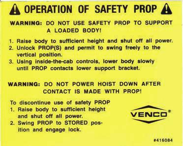
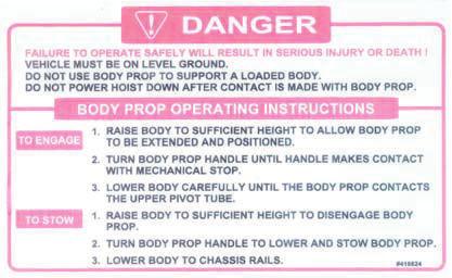
40 REPLACEMENT PARTS LIST ITEM PART NUMBER QTY DESCRIPTION SCISSORS ASSEMBLY HYDRAULIC CYLINDER 3!HHCS HEX HEAD CAP SCREW - 1/2"-13 x 2-3/4" LG. GR 8 4!LWSH LOCK WASHER - 1/2" 5!HNUT HEX NUT 1/2" /8 X 3-1/2 CLEVIS PIN ASSEMBLY BODY PROP WELDED ASSEMBLY ALT01 1 CONTROL HANDLE WELDED ASSY. W/31 ADJ. LINK REPLACEMENT PARTS DWG REF MANUFACTURING, INC. TITLE REPL. PARTS LIST VC 620 W /LINK. PROP DATE A SUPERCEDES SECTION H
41 40058-HD SINGLE-ACTING HYDRAULIC POW ER UNIT SERVICE PARTS LIST MANUFACTURING, INC. TITLE DATE SECTION SERVICE PARTS LIST VC 620/ SUPERCEDES - H HD
42
43
44
45
46
47

48 VENCO HOISTS LIMITED WARRANTY POLICY Venco products are built to last we guarantee them. As a purchaser of any new Venco product covered by warranty, you will receive 3 years of the most complete coverage available and, at no added cost to you. 3-Year Limited Warranty Policy This limited policy warrants new products of Venco to be free from defects in material and workmanship for a period of three (3) years from date of original installation. OEM products or accessories purchased by Venco as part of or offered with our product will carry the OEM manufacturer s respective warranty. Our warranty covers: Repair or replacement of product Labor to repair or replace product Freight to return and/or replace product We shall not be liable for any contingent liabilities arising out of the improper function of any products. Warranty shall become void if the product is improperly installed, modified, damaged, abused or used for application other than intended use. Venco hoists are designed for and intended to be used on stationary trucks dumping on firm and level ground. Spreading applications and/or shock unloading are strictly prohibited and will void this warranty. There is no warranty of merchantability, fitness for a particular purpose, warranty arising from course of dealing or usage of trade, or any other implied or expressed warranty, except as made specifically herein. This warranty supersedes all previous warranties, written or implied. Warranty Claims Venco Venturo Industries LLC will make a good faith effort for prompt correction or other adjustment with respect to any product, which proves to be defective after our inspection and within the warranty period. Before any repairs are attempted or before returning any product, your Venco Distributor is required to obtain a warranty claim number. This number is necessary for any claim to be considered. To obtain a warranty claim number, Venco requires the model and serial number. Only authorized Venco Distributors can perform warranty. For the name and address of your local Venco Distributor call the Warranty Claim Department WARNING - It is the responsibility of the installer to ensure the installation is completed according to the manufacturer's recommendations, ensure the ultimate user understands how to operate product in a safe manner, and understands the need for regular service and maintenance by an authorized Venco Distributor. No modifications or alterations may be made to any Venco product without the expressed written consent of Venco Venturo Industries LLC. Installation of any Venco product must be done by an authorized Venco Distributor, to the standards of the industry; including maintenance, service and affixing of all instruction, safety and warning decals. Users should be instructed as to the safe operation at time of delivery. Maintenance, service, operation and safety warning decals are available on request from Venco Venturo Industries LLC. VENCO VENTURO INDUSTRIES LLC BEST PLACE CINCINNATI, OHIO P: F: Revised: January _VNC3-D
PAGE DESCRIPTION REF. NO.
 TABLE OF CONTENTS VC 620 MANUAL PAGE DESCRIPTION REF. NO. 1 READ THIS FIRST... 416733 2 IMPORTANT WARNING... 416086 3 WARNING AND CAUTION DECAL LOCATIONS... 416128 4 DECAL DRAWINGS & LIST... 628820 5 VC
PAGE DESCRIPTION REF. NO.
 TABLE OF CONTENTS VC 628 / 5520 / 6620 MANUAL PAGE DESCRIPTION REF. NO. 1 READ THIS FIRST... 416756 2 IMPORTANT WARNING... 416086 3 WARNING AND CAUTION DECAL LOCATIONS... 416128 4 DECAL DRAWINGS & LIST...
TABLE OF CONTENTS VC 620 / 628 / 5520 / 6620 / 6628 MANUAL TABLE OF CONTENTS F VC VC 6628 PAGE DESCRIPTION REF. NO.
 TABLE OF CONTENTS VC 620 / 628 / 5520 / 6620 / 6628 MANUAL PAGE DESCRIPTION REF. NO. 1 READ THIS FIRST... 416733 2 IMPORTANT WARNING... 416086 3 WARNING AND CAUTION DECALS... 416128 4 VC 620 CAPACITIES...
PAGE DESCRIPTION REF. NO.
 TABLE OF CONTENTS VC 416 / 516 MANUAL PAGE DESCRIPTION REF. NO. 1 READ THIS FIRST... 416723 2 IMPORTANT WARNING... 416272 3 BODY PROP AND WARNING / CAUTION DECALS... 416288 4 DECAL LOCATIONS... 416128
PAGE DESCRIPTION REF. NO.
 TABLE OF CONTENTS VC 416 / 516 MANUAL PAGE DESCRIPTION REF. NO. 1 READ THIS FIRST... 416723 2 IMPORTANT WARNING... 416272 3 BODY PROP AND WARNING / CAUTION DECALS... 416288 4 DECAL LOCATIONS... 416128
HT40KX & HT50KX Accessories (Outriggers, Pedestals, Boom Rests)
") TABLE OF CONTENTS HT40KX & HT50KX Accessories (Outriggers, Pedestals, Boom Rests) SECTION 100 DESCRIPTION& SPECIFICATIONS 23982 24962 / 25100 OUTRIGGER APPLICATIONS CHART 23984 INSTALLATION DRAWING- 24971-FP
TABLE OF CONTENTS HT40KX & HT50KX Accessories (Outriggers, Pedestals, Boom Rests) SECTION 100 DESCRIPTION& SPECIFICATIONS 23982 24962 / 25100 OUTRIGGER APPLICATIONS CHART 23984 INSTALLATION DRAWING- 24971-FP
12110BESTPLACE CINCINNATI,OHIO PHONE FAX
 12110BESTPLACE CINCINNATI,OHIO 45241 PHONE 1-800-226-2238 FAX 1-513-326-5427 www.venturo.com BLANK TABLE OF CONTENTS - CRANE ACCESSORIES - INSTALLATION MANUAL CRANE PEDESTALS PART NUMBER HEIGHT(S) CRANE
12110BESTPLACE CINCINNATI,OHIO PHONE FAX
 12110BESTPLACE CINCINNATI,OHIO 45241 PHONE 1-800-226-2238 FAX 1-513-326-5427 www.venturo.com BLANK TABLE OF CONTENTS - 25100-PH(E) OUTRIGGERS - INSTALLATION MANUAL DESCRIPTION INSTALLATION SECTION 01 OUTRIGGER
PAGE DESCRIPTION REF. NO.
 TABLE OF CONTENTS VC 416 / 516 MANUAL PAGE DESCRIPTION REF. NO. 1 READ THIS FIRST... 416733 2 IMPORTANT WARNING... 416272 3 BODY PROP AND WARNING / CAUTION DECALS... 416288 4 DECAL LOCATIONS... 416128
CE-104 TABLE OF CONTENTS CE-1500-FB OWNER'S MANUAL TABLE OF CONTENTS CE-1500-FB DESCRIPTION & SPECIFICATIONS DIMENSIONS AND CAPACITIES
 TABLE OF CONTENTS CE500FB OWNER'S MANUAL SECTION 00 CE020 SECTION 50 DESCRIPTION & SPECIFICATIONS DIMENSIONS AND CAPACITIES SAFETY CE044 CRANE SAFETY AND HAZARDS 2376 DECAL DRAWINGS & LIST 2409 DECAL DRAWING
12110BESTPLACE CINCINNATI,OHIO PHONE FAX
 20BESTPLACE CINCINNATI,OHIO 4524 PHONE 8002262238 FAX 533265427 www.venturo.com TABLE OF CONTENTS VC500FB OWNER'S MANUAL SECTION 00 CEV46 CEV62 DESCRIPTION & SPECIFICATIONS DIMENSIONS AND CAPACITIES WIRE
LR-416, LR-165, LR-25 INSTALLATION AND OPERATION MANUAL
 RUGBY MANUFACTURING CO. INDUSTRIAL PARK 515 1st STREET NE RUGBY, NORTH DAKOTA 58368 03 5753 LR-416, LR-165, LR-25 INSTALLATION AND OPERATION MANUAL To Be Filled In By Installer Hoist Installed: Hoist Serial
SECTION 100 DESCRIPTION SPECIFICATIONS
 SECTION 100 DESCRIPTION & SPECIFICATIONS 7607100A SPECIFICATIONS AND OPERATING FEATURES ET25KX-10/20 SPECIFICATIONS 12 VOLT BATTERY OPERATED 25,000 FT-LBS OVERTURNING MOMENT (Or as limited by truck stability)
1002 Wayne Avenue Chambersburg, PA Fax: DI-100 OWNER S MANUAL. General Information Instructions Maintenance
 1002 Wayne Avenue Chambersburg, PA 17201 717.261.0922 Fax: 717.264.5581 DI-100 OWNER S MANUAL General Information Instructions Maintenance TABLE OF CONTENTS Installation Instructions... 4-5 Installation
Operating & Maintenance
 TL & C SERIES Operating & Maintenance A B C D E F TO RAISE HOIST 1. Start Engine in neutral 2. Depress the clutch and engage the P.T.O. 3. Release the clutch and open the hydraulic valve. If the pump squeals,
Technical Support Line: (952) Hanover Ave. Lakeville, MN
 Hanover Ave. Lakeville, MN") Technical Support Line: (952) 985-5675 Email: Sales@QA1.net 21730 Hanover Ave. Lakeville, MN 55044 www.qa1.net INSTALLATION INSTRUCTIONS QA1 1967-1979 Mopar A-Body Rear 6 link Conversion System QA1 p/n
Technical Support Line: (952) 985-5675 Email: Sales@QA1.net 21730 Hanover Ave. Lakeville, MN 55044 www.qa1.net INSTALLATION INSTRUCTIONS QA1 1967-1979 Mopar A-Body Rear 6 link Conversion System QA1 p/n
Owner s Manual TC-515 with Reversed Hoist, Sub-Frame, Deck, & Hitch Mount
 Proudly built in the USA Owner s Manual TC-55 with Reversed Hoist, Sub-Frame, Deck, & Hitch Mount TruckCraft Corporation Chambersburg, PA -800-755-87 Copyright c 0 www.truckcraft.com TruckCraft Corporation
BUILD YOUR OWN TRUCK HOIST ASSEMBLY AND MOUNTING INSTRUCTIONS FOR TRUCK HOIST (SINGLE LEVER) ITEM #
 ITEM #") 1 of 9 481 Panet Road Winnipeg, MB R2C 2Z1 BUILD YOUR OWN TRUCK HOIST ASSEMBLY AND MOUNTING INSTRUCTIONS FOR TRUCK HOIST (SINGLE LEVER) ITEM #1561075 TRUCK HOIST 7 TON (SINGLE LEVER) ITEM # 1200188 1.
1 of 9 481 Panet Road Winnipeg, MB R2C 2Z1 BUILD YOUR OWN TRUCK HOIST ASSEMBLY AND MOUNTING INSTRUCTIONS FOR TRUCK HOIST (SINGLE LEVER) ITEM #1561075 TRUCK HOIST 7 TON (SINGLE LEVER) ITEM # 1200188 1.
Website: ELIMINATOR MD. (701) (800)
 (800)") Website: www.tbei.com E-mail: sales@tbei.com ELIMINATOR MD www.rugbymfg.com sales@rugbymfg.com (701) 776-5722 (800) 533-0494 1228633 1 DATE PURCHASED BODY SERIAL NUMBER HOIST SERIAL NUMBER CYLINDER SERIAL
Website: www.tbei.com E-mail: sales@tbei.com ELIMINATOR MD www.rugbymfg.com sales@rugbymfg.com (701) 776-5722 (800) 533-0494 1228633 1 DATE PURCHASED BODY SERIAL NUMBER HOIST SERIAL NUMBER CYLINDER SERIAL
CRYSTEEL S HOIST. this manual must be included with the vehicle after completing the installation.
 Website: www.tbei.com E-mail: sales@tbei.com CRYSTEEL S STINGRAY HOIST this manual must be included with the vehicle after completing the installation. Web Site E-Mail Phone (507) 726-2728 www.crysteel.com
LR-26B, LR-27B, LR-28A, or LR-623 INSTALLATION AND OWNER'S MANUAL
 INDUSTRIAL PARK 515 1ST STREET NORTH EAST RUGBY, ND 58368 03 5804 LR-26B, LR-27B, LR-28A, or LR-623 INSTALLATION AND OWNER'S MANUAL Hoist Installed: Hoist Serial #: To Be Filled In By Installer Pump Installation
FRONT DRIVELINE MODIFICATION MAY BE NECESSARY!!!!
 INSTALLATION INSTRUCTIONS FOR 2009 DODGE 2500/3500 4WD & 1500 Mega Cab 6 SUSPENSION SYSTEM PART NUMBER 7206 Requires the following parts (sold separately) for a complete installation: Front Coil Spring
LR-3510 Install and Operation Manual
 RUGBY MANUFACTURING CO. INDUSTRIAL PARK 515 1st St. NE. RUGBY, NORTH DAKOTA 58368 03 6048 Install and Operation Manual LATEST EDITION: 1st (January 4, 2001) FIRST EDITION: January 4, 2001 Page 2 of 9 WARNINGS:
INSTALLATION AND INSTRUCTIONAL MANUAL ELECTRIC V-BOX MATERIAL SPREADERS
 0050-00-00 07-06-00 Contents SAFETY... MOUNTING INSTRUCTION... -5 ELECTRICAL CONTROL INSTRUCTION... 6-9 V-BOX PARTS DIAGRAMS AND LISTINGS... 0-5 SPINNER PARTS DIAGRAMS AND LISTINGS... 6-0 DRIVE SHAFT,
ALUMINUM & STEEL CAR CARRIERS
 OWNER'S MANUAL ALUMINUM & STEEL CAR CARRIERS INSTALLATION, OPERATION, MAINTENANCE & PARTS NOTE: MANUAL including SPECIFICATIONS, subject to change without notice All ratings specified are based on structural
ASSEMBLY / OPERATION INSTRUCTIONS. Low Profile Motorcycle Dolly
 ASSEMBLY / OPERATION INSTRUCTIONS 1,500LB CAPACITY Low Profile Motorcycle Dolly Model: 03-CG1500-01(B1) WARNING BEFORE USE PLEASE READ ALL WARNINGS AND INSTRUCTIONS TO PREVENT SERIOUS INJURY Drop-Tail
MODEL LR-2066 & LR-2866A HOIST INSTALLATION AND OPERATION MANUAL
 TRUCK BODIES & EQUIPMENT INTERNATIONAL, Inc. Website: www.rugbymfg.com E-mail: sales@rugbymfg.com Phone: 1-800-869-9162 03 5839 MODEL LR-2066 & LR-2866A HOIST INSTALLATION AND OPERATION MANUAL Hoist Serial
Rugby Manufacturing SR-Series Hoist Manual. Preface INSTALLATION & OPERATION MANUAL
 Preface INSTALLATION & OPERATION MANUAL INTRODUCTION IMPORTANT!! Read this manual thoroughly prior to installation and operation. This manual outlines the installation and operation of an SR-series hoist
MARATHON TELESCOPIC HOIST
 Website: www.tbei.com E-mail: sales@tbei.com CRYSTEEL S MARATHON TELESCOPIC HOIST this manual must be included with the vehicle after completing the installation. Web Site E-Mail Phone (507) 726-2728 www.crysteel.com
Premium Supply. Direct Push. Models PCK-3530-DP PCK DP PCK-530-DP. Operator s Manual and Installation Instructions
 Direct Push Models PCK-3530-DP PCK-3530-2DP PCK-530-DP Operator s Manual and Installation Instructions Premium Supply 2038 West Interstate 30 866-934-0777 Proud members of: and June 20, 2018 Table of Contents
DIRECT MOUNT PUMP INSTALLATION AND OPERATION MANUAL (Valve/Reservoir: M-8CR06-9RQT. Pump: GP916CCW)
") TRUCK BODIES & EQUIPMENT INTERNATIONAL, Inc. Website: www.tbei.com E-mail: sales@tbei.com Phone: 1-800-869-9162 Rugby 1-800-255-4345 Heil 1-800-533-0494 Crysteel DIRECT MOUNT PUMP INSTALLATION AND OPERATION
TRUCK BODIES & EQUIPMENT INTERNATIONAL, Inc. Website: www.tbei.com E-mail: sales@tbei.com Phone: 1-800-869-9162 Rugby 1-800-255-4345 Heil 1-800-533-0494 Crysteel DIRECT MOUNT PUMP INSTALLATION AND OPERATION
Buhler Versatile 23XX/24XX, Versatile 9X80, and New Holland Versatile 9X8X SmarTrax MD Installation Manual. P/N Rev A 04/16 E23635
 Buhler Versatile 23XX/24XX, Versatile 9X80, and New Holland Versatile 9X8X SmarTrax MD Installation Manual P/N 016-5030-065 Rev A 04/16 E23635 Copyright 2014, 2016 Disclaimer While every effort has been
INSTALLATION INSTRUCTIONS AND OWNER S MANUAL
 INSTALLATION INSTRUCTIONS AND OWNER S MANUAL Thank you for purchasing the AlloyCover from WeatherTech. Manufactured with pride using superior quality materials and workmanship. With proper care, your cover
ASSEMBLY / OPERATION INSTRUCTIONS. Low Profile / Stand-Up Motorcycle Dolly
 ASSEMBLY / OPERATION INSTRUCTIONS 1,500LB CAPACITY Low Profile / Stand-Up Motorcycle Dolly Model: 03-CGPR1500-01(C) WARNING BEFORE USE PLEASE READ ALL WARNINGS AND INSTRUCTIONS TO PREVENT SERIOUS INJURY
OWNER S GUIDE 8A DURALIFT II 13,200 LB. CAPACITY. Link Mfg. Ltd th St. N.E. Sioux Center, IA USA
 OWNER S GUIDE 8A000715 DURALIFT II 13,200 LB. CAPACITY Link Mfg. Ltd. 223 15th St. N.E. Sioux Center, IA USA 51250-2120 www.linkmfg.com QUESTIONS? CALL CUSTOMER SERVICE 1-800-222-6283 DEALER / INSTALLER:
Case IH 3320, 3330, and Booms AutoBoom Installation Manual. P/N Rev B 06/15
 Case IH 3320, 3330, and 4420-0120 Booms AutoBoom Installation Manual P/N 016-0230-091 Rev B 06/15 Copyright 2009 Disclaimer While every effort has been made to ensure the accuracy of this document, Raven
AN AFFILIATE OF. The Godwin Group 200 CHAMPION DRIVE DUNN, N.C (910) FAX: (910) CONVERSION HOIST
 FAX: (910) CONVERSION HOIST") CHAMPION Hoist and Equipment AN AFFILIATE OF The Godwin Group 200 CHAMPION DRIVE DUNN, N.C. 28334 (910) 897-4995 FAX: (910) 897-7306 CONVERSION HOIST Operation & Installation Manual Notice: This manual
CHAMPION Hoist and Equipment AN AFFILIATE OF The Godwin Group 200 CHAMPION DRIVE DUNN, N.C. 28334 (910) 897-4995 FAX: (910) 897-7306 CONVERSION HOIST Operation & Installation Manual Notice: This manual
INSTALLATION INSTRUCTIONS AND OWNER S MANUAL
 INSTALLATION INSTRUCTIONS AND OWNER S MANUAL Thank you for purchasing the AlloyCover from WeatherTech. Manufactured with pride using superior quality materials and workmanship. With proper care, your cover
Instruction Manual. Direct Drive & 5:1 Gear Reduction Under Tailgate Spreaders
 909 Tyler Blvd. Mentor, Ohio 00 Phone (0) 9- Fax (0) 9-0 Toll-Free Fax 00--00 saltdogg.com Direct Drive & : Gear Reduction Under Tailgate Spreaders NOTE: This manual applies to spreaders with a top screen.
Installation Instructions READ THOROUGHLY BEFORE BEGINNING Signature Series Rail Kit Dodge Ram Trucks-all, including Mega-cabs
 INDEX Failure to follow all of these instructions may result in death or serious injury!. GUIDELINES FOR MATCHING TOW VEHICLE AND TRAILER. Pages -. DRILLED AND BOLTED INSTALLATION FIGURE. Page 4. NO-DRILL,
Installation Instructions
 909 Tyler Blvd. Mentor, Ohio 060 Phone (0) 97-8888 Fax (800) 8-800 www.saltdogg.com Installation Instructions Direct Drive Hydraulic Replacement Tailgate Spreader REPLACEMENT TAILGATE SPREADER WARRANTY
MODEL TB-8, TB-10, TB-12, & TB-14 TRAILER HOIST INSTALLATION AND OPERATION MANUAL
 TRUCK BODIES & EQUIPMENT INTERNATIONAL, Inc. Website: www.tbei.com E-mail: sales@tbei.com Phone: 1-800-869-9162 1-800-533-0494 090001 MODEL TB-8, TB-10, TB-12, & TB-14 TRAILER HOIST INSTALLATION AND OPERATION
Installation Instructions
 9049 Tyler Blvd. Mentor, Ohio 44060 Phone (440) 974-8888 Fax (440) 974-0165 Toll-Free Fax 800-841-8003 saltdogg.com TGS06 Salt Spreader Installation Instructions Safety Precautions WARNING Observe the
Grapple Kit Install & Grapple Bucket Manual
 Grapple Kit Install & Grapple Bucket Manual Model # Serial # Rev. 10/13 Rylind Manufacturing, Inc. 2801 Youngfield St Suite 250 Golden, CO 80401 Business/Sales Offices: 303-979-3548 Manufacturing Plant:
WEAVER JACK CORP. MASTER PARTS PRICE & IDENTIFICATION LIST. (517) Fax (517) MINIMUM BILLING $20.00
 Fax (517) MINIMUM BILLING $20.00") EFFECTIVE JULY 1, 2014 WEAVER JACK CORP. MASTER PARTS PRICE & IDENTIFICATION LIST (517) 263-6500 Fax (517) 263-2810 MINIMUM BILLING $20.00 THIS PRICE LIST SUPERSEDES ALL PREVIOUS PARTS PRICE LISTS (Prices
EFFECTIVE JULY 1, 2014 WEAVER JACK CORP. MASTER PARTS PRICE & IDENTIFICATION LIST (517) 263-6500 Fax (517) 263-2810 MINIMUM BILLING $20.00 THIS PRICE LIST SUPERSEDES ALL PREVIOUS PARTS PRICE LISTS (Prices
!"" #$% "!&' ( ( ) *
 *") !"" #$% "!&' (( ) * FunPop Assembly Manual Model # 2649CR Part No. 59406CR Revised: October 2004 Cincinnati, OH 45241-4807 USA INSTALLATION INSTRUCTIONS Checking Shipment Unpack carton and check thoroughly
!"" #$% "!&' (( ) * FunPop Assembly Manual Model # 2649CR Part No. 59406CR Revised: October 2004 Cincinnati, OH 45241-4807 USA INSTALLATION INSTRUCTIONS Checking Shipment Unpack carton and check thoroughly
MODEL NO & UP MODEL NO & UP MODEL NO & UP MODEL NO & UP
 MODEL NO. -900 & UP MODEL NO. 00-900 & UP MODEL NO. 0-900 & UP MODEL NO. 0-900 & UP SKID SPRAYER FORM NO. 99-055 REV. B SET-UP AND PARTS LIST Refer to the illustrated Parts List for the details of parts
INSTALLATION INSTRUCTIONS FOR FORD 4WD SUPER DUTY F /2 COIL SPRING SUSPENSION SYSTEM
 INSTALLATION INSTRUCTIONS FOR 2005-07 FORD 4WD SUPER DUTY F250-350 4 1/2 COIL SPRING SUSPENSION SYSTEM Requires the following parts (sold separately) for a complete installation: KIT PART NUMBER (6345
FRONT DRIVELINE MODIFICATION MAY BE NECESSARY!!!!
 DODGE 2500/3500 4WD 4.5 SUSPENSION SYSTEM Requires the following parts (sold separately) for a complete installation: Front Coil Spring Box depending on Gas or Diesel/V0: Gas (Hemi) P/N 7004GS Diesel/V0
!"" #$% "!&' ( ( ) *
 *") !"" #$% "!&' (( ) * FunPop CART Assembly Manual Model # 2689 CARTS Part No. 59411 Revised: FEB 2009 Cincinnati, OH 45241-4807 USA INSTALLATION INSTRUCTIONS Checking Shipment Unpack all cartons and check
!"" #$% "!&' (( ) * FunPop CART Assembly Manual Model # 2689 CARTS Part No. 59411 Revised: FEB 2009 Cincinnati, OH 45241-4807 USA INSTALLATION INSTRUCTIONS Checking Shipment Unpack all cartons and check
TT-12 OWNERS MANUAL/PARTS LIST
 TOPLIFTER Tailgates By THIEMAN TT-12 OWNERS MANUAL/PARTS LIST SHOWN WITH OPTIONAL 2 PC. ALUMINUM PLATFORM! IMPORTANT! KEEP IN VEHICLE! PLEASE READ AND UNDERSTAND THE CONTENTS OF THIS MANUAL BEFORE OPERATING
SPECIAL TOOLS REQUIRED:
 INSTALLATION INSTRUCTIONS FOR 2010-15 TOYOTA 4RUNNER WITH XREAS SUSPENSION 3 SUSPENSION LIFT KIT PART NUMBER 432X WARNING!!! READ AND UNDERSTAND ALL INSTRUCTIONS BEFORE PROCEEDING. MAKE SURE THAT YOU HAVE
DIRECT MOUNT PUMP INSTALLATION AND OPERATION MANUAL (Valve/Reservoir: W15-8CR-21 QT Pump: GP2041)
") TRUCK BODIES & EQUIPMENT INTERNATIONAL, Inc. Website: www.tbei.com E-mail: sales@tbei.com Phone: 1-800-869-9162 Rugby 1-800-533-0494 Crysteel 1-800-255-4345 Heil DIRECT MOUNT PUMP INSTALLATION AND OPERATION
TRUCK BODIES & EQUIPMENT INTERNATIONAL, Inc. Website: www.tbei.com E-mail: sales@tbei.com Phone: 1-800-869-9162 Rugby 1-800-533-0494 Crysteel 1-800-255-4345 Heil DIRECT MOUNT PUMP INSTALLATION AND OPERATION
Illustrated Parts Breakdown Manual EZ LOADER. Model EZ12 (Pre-01/08)
") Illustrated Parts Breakdown Manual EZ LOADER Model EZ12 (Pre-01/08) Xtreme Manufacturing 1415 West Bonanza Road Las Vegas, NV 89106 (702) 858-2404 www.xtrememanufacturing.com Copyright 2008 By Xtreme Manufacturing
Illustrated Parts Breakdown Manual EZ LOADER Model EZ12 (Pre-01/08) Xtreme Manufacturing 1415 West Bonanza Road Las Vegas, NV 89106 (702) 858-2404 www.xtrememanufacturing.com Copyright 2008 By Xtreme Manufacturing
Parts & Service Manual Excavator Railgear
 DIVERSIFIED METAL FABRICATORS Parts & Service Manual Excavator Railgear April 2018 SERIAL NUMBER (FRONT) SERIAL NUMBER (REAR) NOTE: Please refer to the serial numbers when ordering parts or inquiring about
Kleen Sweep 27. Model: C OPERATION SERVICE PARTS CARE. Revised 8/02
 Kleen Sweep 27 Model: C89000-00 OPERATION SERVICE PARTS CARE Revised 8/02 ASSEMBLY INSTRUCTIONS Unpacking Instructions This unit is packed with a sidearm assembly and sidebroom inside the hopper. Refer
Operation & Service Manual
 Operation & Service Manual Model: 02-1248-0112 12 Ton Single Stage Jack 11/2004 Rev. 02 Includes Illustrated Parts Lists 1740 Eber Rd Tronair, Inc. Phone: (419) 866-6301 Holland, OH 43528-9794 www.tronair.com
12110BESTPLACE CINCINNATI,OHIO PHONE FAX
 0BESTPLACE CINCINNATI,OHIO 454 PHONE -800-6-38 FAX -53-36-547 www.venturo.com Dear Venturo VC000 Purchaser, Thank You! Thank you for your purchase of the Venturo VC000 Van Crane. This crane was carefully
INSTALLATION INSTRUCTIONS QA1 P/N x400, x500, x600, x400, x500, x F100 Front Coil-over Suspension System
 INSTALLATION INSTRUCTIONS QA1 P/N 52620-x400, 52620-x500, 52620-x600, 52621-x400, 52621-x500, 52621-x600 65-72 F100 Front Coil-over Suspension System TOOLS AND SUPPLIES REQUIRED Floor Jack Two (2) Jack
HR-520 HOIST. Installation & Operation Manual. To Be Filled In By Installer. Pump Installation And Operation Manual#: In Service Date: Dealer:
 Website: www.tbei.com E-mail: sales@tbei.com Phone: 1-800-869-9162 Rugby 1-800-255-4345 DuraClass 1-800-533-0494 Crysteel HR-520 HOIST Installation & Operation Manual To Be Filled In By Installer Hoist
INSTRUCTION MANUAL TITAN 16K - Fifth Wheel Hitch Plymouth MI
 You can take it with you. INSTRUCTION MANUAL TITAN 16K - Fifth Wheel Hitch Plymouth MI Product No. 30866 DEALER/INSTALLER: END USER: (1) Provide this Manual to end user. (2) Physically demonstrate hitching
Assembly, Installation, Operation and Maintenance Instructions. Base Rail Bracket Kit. For updates see PRODUCT SUPPORT tab at
 Assembly, Installation, Operation and Maintenance Instructions P/N: 31408 Base Rail Bracket Kit For updates see PRODUCT SUPPORT tab at www.huskytow.com Provide a copy of these Instructions to the end user
INSTALLATION INSTRUCTIONS
 TM WEIGHTLIFTER Tailgates By THIEMAN TWL 125, 16, 20 INSTALLATION INSTRUCTIONS! IMPORTANT! KEEP IN VEHICLE! PLEASE READ AND UNDERSTAND THE CONTENTS OF THIS MANUAL BEFORE OPERATING THE EQUIPMENT. NTEA T
HR-540/HR-550 HOIST Installation & Operation Manual
 Website: www.tbei.com E-mail: sales@tbei.com Phone: 1-800-869-9162 Rugby 1-800-255-4345 DuraClass 1-800-533-0494 Crysteel HR-540/HR-550 HOIST Installation & Operation Manual To Be Filled In By Installer
JK HD Skid Plate for Rear Falcon Shocks
 1 JK HD Skid Plate for Rear Falcon Shocks Kit # 36-07-01-300 Tools needed: Important Notes: Prior to beginning this or any installation read these instructions to familiarize yourself with the required
MODEL 5500 Tire Repair Station
 MODEL 5500 Tire Repair Station Installation, Operation and Repair Parts Information Branick Industries, Inc. 4245 Main Ave P.O. Box 1937 Fargo, North Dakota 58103 P/N: 81-0047C TABLE OF CONTENTS SAFETY
INSTRUCTION MANUAL 16K - Fifth Wheel Hitch
 You can take it with you. INSTRUCTION MANUAL 16K - Fifth Wheel Hitch Product No. 30047 DEALER/INSTALLER: END USER: (1) Provide this Manual to end user. (2) Physically demonstrate hitching and unhitching
Cardinal DETECTO. PORTABLE PLATFORM SCALES Digital Type Series 850F Owner s Manual
 Cardinal DETECTO PORTABLE PLATFORM SCALES Digital Type Series 850F Owner s Manual CARDINAL SCALE MFG. CO. PO BOX 151, WEBB CITY, MO 64870 0066-M176-O1 Rev H 10/06 417-673-4631 www.cardinalscale.com Printed
INSTALLATION INSTRUCTIONS MOUNTING KIT GENERAL MOTORS Chevrolet Silverado/GMC Sierra 2500HD & 3500HD
 INSTALLATION INSTRUCTIONS MOUNTING KIT GENERAL MOTORS 2001-2006 Chevrolet Silverado/GMC Sierra 2500HD & 3500HD DEALER/INSTALLER: (1) Provide this Manual to end user. END USER: (1) Save this Manual for
Instruction Manual 15K - Fifth Wheel Hitch Part Number 6030 & 6031
 DEALER/INSTALLER: (1) Provide this Manual to end user. (2) Physically demonstrate hitching and unhitching procedures in this Manual to end user. (3) Have end user demonstrate that he/she understands procedures.
CENTURY 30 SERIES INSTALLATION, OPERATION, MAINTENANCE & PARTS
 CENTURY L E G E N D A R Y L E A D E R S H I P OWNER'S MANUAL 30 SERIES INSTALLATION, OPERATION, MAINTENANCE & PARTS NOTE: MANUAL including SPECIFICATIONS, subject to change without notice All ratings specified
Rugby Manufacturing Direct Mount Unit Manual
 Preface INSTALLATION & OPERATION MANUAL INTRODUCTION IMPORTANT!! Read this manual thoroughly prior to installation and operation. This manual outlines the installation and operation of a Direct Mount unit
PARTS LIST INCLUDED IN KIT TORQUE SPECIFICATIONS PRODUCT SAFETY LABEL MUST BE INSTALLED INSIDE CAB IN PLAIN VIEW OF ALL OCCUPANTS.
 INSTALLATION INSTRUCTIONS FOR 2010-15 TOYOTA 4RUNNER SR5 AND SPORT (Non-Air Leveling & Non-X-REAS) AND FOR 2010-14 TOYOTA FJ CRUISER 2WD & 4WD 3 SUSPENSION LIFT KIT PART NUMBER 432 WARNING!!! READ AND
INSTALLATION INSTRUCTIONS BASE RAIL MOUNTING KIT GM COMPOSITE BED 58208
 INSTALLATION INSTRUCTIONS BASE RAIL MOUNTING KIT GM COMPOSITE BED 58208 DEALER/INSTALLER: (1) Provide this Manual to end user. (2) Physically demonstrate procedures in this Manual to end user. (3) Have
RIGID LIFT INSTALLATION & OPERATION MANUAL MODELS: RL-B10 THRU RL-L125
 RIGID LIFT INSTALLATION & OPERATION MANUAL MODELS: RL-B10 THRU RL-L125 THIS MANUAL IS TO BE USED IN CONJUNCTION WITH THE APPROPRIATE PUMP INSTALLATION MANUAL AND HOIST PARTS LIST. IMPORTANT FAILURE TO
Installation Instructions **THIS RAIL MOUNTING KIT USES 11 BOLTS**
 Installation Instructions CUSTOM QUICK INSTALL MOUNTING KIT FORD SUPER DUTY Part Numbers: 50074 WARNING:Under no circumstances do we recommend exceeding the towing vehicle manufacturers recommended vehicle
! Williams Machine & Tool 204 Plastic Lane Pump Serial No. Monticello, IA USA
 NOTICE: This manual is to remain with truck after pump unit is installed. MACHINE & TOOL Hydraulic Piston Pump Units Operating, Mounting and Safety Instructions for: Model 20 Pump Model 40 Pump Model F98
RPD SERIES HEAVY AND SEVERE DUTY SNOW PLOW
 RPD SERIES HEAVY AND SEVERE DUTY SNOW PLOW Model: Serial Number: Rev. 01/14 Rylind Manufacturing, Inc. 2801 Youngfield St Suite 250 Golden, CO 80401 Main Offices: 303-979-3548 Manufacturing Plant: 970-522-2859
Model E600 Tarping System
 10 Boulder Parkway N. Oxford, MA 01537 866-353-5826 pioneersales@wastequip.com www.pioneercoverall.com Model E600 Tarping System Installation Instructions WARNING: In order to prevent damage, the tarp
Richmond Conveyor. Hydraulic Ultimate Manual. January 2013
 Richmond Conveyor Hydraulic Ultimate Manual January 2013 Table of Contents Operators Manual Removing conveyor from truck Maintenance checklist Maintenance kit material list Safety information Index Installation
DC Series Installation Manual (# )
") DC Series Installation Manual (# 101630) Page 1 of 33 In this booklet you will find: TOWER INSTALLATION... 3 U-Bolt Style mount... 4 Side Frame Style mount... 4 PIVOT INSTALLATION... 5 External Pivot Installation:
DC Series Installation Manual (# 101630) Page 1 of 33 In this booklet you will find: TOWER INSTALLATION... 3 U-Bolt Style mount... 4 Side Frame Style mount... 4 PIVOT INSTALLATION... 5 External Pivot Installation:
Premium Supply. Tilt Deck. Models PCK-TD PCK-PTD. Operator s Manual and Installation Instructions
 Tilt Deck Models PCK-TD PCK-PTD Operator s Manual and Installation Instructions Premium Supply 2038 West Interstate 30 866-934-0777 Proud members of: and June 1, 2015 Table of Contents Introduction...
HM860 FLOWMETER OPERATOR S MANUAL DO NOT USE OR OPERATE THIS EQUIPMENT UNTIL THIS MANUAL HAS BEEN READ AND THOROUGHLY UNDERSTOOD
 HM860 FLOWMETER OPERATOR S MANUAL DO NOT USE OR OPERATE THIS EQUIPMENT UNTIL THIS MANUAL HAS BEEN READ AND THOROUGHLY UNDERSTOOD PART NUMBER 393-008-020 Rev. C Table of Contents TABLE OF CONTENTS 393-008-020
INSTALLATION AND MAINTENANCE MANUAL
 TYPE 2 PTO INSTALLATION AND MAINTENANCE MANUAL P.O. Box 8148 Wichita Falls, Texas 76307 1600 Fisher Rd. Wichita Falls, Texas 76305 Phone: (940) 7611971 Fax: (940) 7611989 www.wptpower.com email: info@wptpower.com
A40 ARTICULATING CRANE MOUNTING AND INSTALLATION INSTRUCTIONS Manual No Rev. 9/2/2003
 A40 ARTICULATING CRANE MOUNTING AND INSTALLATION INSTRUCTIONS Manual No. 407900001 Rev. 9/2/2003 Mailing Address: P.O. Box 580697 Tulsa, OK 74158-0697 Physical Address: Phone (918) 836-0463 4707 N. Mingo
HL4K PLATFORM LIFT INSTRUCTIONS
 HL4K PLATFORM LIFT INSTRUCTIONS REIMANN & GEORGER CORPORATION MARINE PRODUCTS P/N 6114--- 6/19/15 BUFFALO, NY TABLE OF CONTENTS CHAPTER TITLE PAGE 1 SAFETY... 1 1.1 Introduction... 1 1.2 Safety Definitions...
INSTALLATION INSTRUCTIONS FOR FORD 4WD SUPER DUTY F COIL SPRING SUSPENSION SYSTEM
 INSTALLATION INSTRUCTIONS FOR 2008-10 FORD 4WD SUPER DUTY F250-350 6 COIL SPRING SUSPENSION SYSTEM Requires the following parts (sold separately) for a complete installation: KIT PART NUMBER (6860) REQUIRES
Instruction Manual. SHPE1500 Salt Dogg Spreader Hopper Poly Electrical 1.5 cubic yards
 9049 Tyler Blvd. Mentor, Ohio 44060 Phone (440) 974-8888 Fax (440) 974-0165 Toll-Free Fax 800-841-8003 buyersproducts.com SHPE1500 Salt Dogg Spreader Hopper Poly Electrical 1.5 cubic yards Instruction
NOTE: LIFETIME PRODUCT WARRANTY
 Carli Suspension: 422 Jenks Circle, Corona, CA 92880 Tech Support: (714) 532-2798 CS-DD30-6-03-D CS-DD30-6-10-D CS-DD30-6-10-D-12MM CS-DD30-6-12-D CS-DD30-6-12-D-12MM NOTE: Please review the product instructions
Rugby Manufacturing TB-8/10/12/14 Hoist Manual. Preface INSTALLATION & OPERATION MANUAL
 Preface INSTALLATION & OPERATION MANUAL INTRODUCTION IMPORTANT!! Read this manual thoroughly prior to installation and operation. This manual outlines the installation and operation of a TB-Series hoist
HIGH DUMP ROLL-OUT BUCKET
 HIGH DUMP ROLL-OUT BUCKET Model # Serial # Rev. 01/14 Rylind Manufacturing, Inc. 2801 Youngfield St Suite 250 Golden, CO 80401 Business/Sales Offices: 303-979-3548 Manufacturing Plant: 970-522-2859 www.rylind.com
Deere G & GP Series Snow Wing Installation
 Deere G & GP Series Snow Wing Installation Model: Serial Number: Rev. 10/13 Rylind Manufacturing, Inc. 2801 Youngfield St Suite 250 Golden, CO 80401 Offices: 303-979-3548 Fax: 303-979-4730 www.rylind.com
INSTALLATION MANUAL. CNH 5088, 6088, 7088 and 5130, 6130, 7130
 INSTALLATION MANUAL FOR Mud Hog Rear Wheel Drive FOR CNH 5088, 6088, 7088 and 5130, 6130, 7130 COMBINES Mud Hog Model Number: CNH42005 A Product of Tuthill Drive Systems P.O. Box 600 Brookston, Indiana
Extreme Short Shaft Kit Part #
 TeraFlex, Inc. 5241 South Commerce Dr. Murray, Utah 84107 Phone/801.288.2585 Fax/801.713.2313 www.teraflex.biz Rev. 24 January 2011 TT PRODUCT INSTALLATION GUIDE Important Notes: Extreme Short Shaft Kit
Read this entire manual before operation begins.
 Read this entire manual before operation begins. Record below the following information which is located on the serial number data plate. Serial No. Model No. Date of Installation Contents Specifications.............
COVER PAGE BASE RAIL MOUNTING KIT 10 BOLT RAIL KIT NOTE!
 COVER PAGE 30035 BASE RAIL MOUNTING KIT 10 BOLT RAIL KIT NOTE! If you have a newer model year truck you must go to one our websites for the most recent updated instructions. www.reeseproducts.com or www.draw-tite.com
INSTALLATION INSTRUCTIONS MOUNTING KIT GENERAL MOTORS Chevrolet Silverado Sierra, GMC 3500HD; Silverado
 INSTALLATION INSTRUCTIONS MOUNTING KIT GENERAL MOTORS 2001-04 Chevrolet Silverado Sierra, GMC 3500HD; 99-2000 Silverado DEALER/INSTALLER: (1) Provide this Manual to end user. END USER: (1) Save this Manual
INSTALLATION INSTRUCTIONS
 INSTALLATION INSTRUCTIONS Thank you for purchasing a LOMAX TM Hard Tri-Fold or Professional Series Cover. Agri-Cover, Inc. proudly manufactured this cover using superior quality materials and workmanship.
INSTALLATION INSTRUCTIONS MOUNTING KIT COMMERCIAL TRUCK FOR 34 OUTSIDE FRAME WIDTH ONLY. Front of vehicle
 INSTALLATION INSTRUCTIONS MOUNTING KIT COMMERCIAL TRUCK FOR 34 OUTSIDE FRAME WIDTH ONLY DEALER/INSTALLER: (1) Provide this Manual to end user. END USER: (1) Save this Manual for future reference. (2) Pass
INSTALLATION INSTRUCTIONS MOUNTING KIT FOR ELITE SERIES
 INSTALLATION INSTRUCTIONS MOUNTING KIT FOR ELITE SERIES DO NOT EXCEED VEHICLE MANUFACTURER S RATING FOR 5th WHEEL TOWING OR MAXIMUM GROSS TRAILER WEIGHT OF 18,000lb. / 8160kg. DEALER/INSTALLER: (1) Provide