PAGE DESCRIPTION REF. NO.
|
|
|
- Norma Dixon
- 5 years ago
- Views:
Transcription
1 TABLE OF CONTENTS VC 628 / 5520 / 6620 MANUAL PAGE DESCRIPTION REF. NO. 1 READ THIS FIRST IMPORTANT WARNING WARNING AND CAUTION DECAL LOCATIONS DECAL DRAWINGS & LIST VC 628 CAPACITIES VC 5520 CAPACITIES VC 6620 CAPACITIES VC 5520/6620 MOUNTING DIMENSIONS VC 628/6628 MOUNTING DIMENSIONS HOIST LIFTING HOLE LOCATIONS MOUNTING INSTRUCTIONS REAR HINGE TO BED MOUNTING ILLUSTRATION MOUNTING INSTRUCTIONS MOUNTING INSTRUCTIONS MOUNTING INSTRUCTIONS MOUNTING INSTRUCTIONS LIFTING ANGLE INSTALLATION CABLE / HANDLE ASSEMBLY INSTRUCTIONS PTO PUMP CABLE INSTALLATION DIRECT MOUNT ("SPLIT") PUMP CONFIG. & REPLACEMENT PARTS LIST BI-ROTATIONAL PUMP INSTALLATION SPDG HOSE CON. DIAGRAM VC SPDG HOSE CON. DIAGRAM VC5520, VC6620, VC HOIST MAINTENANCE AND OPERATION GREASE POINTS FOR HOISTS BODY PROP OPERATION RESERVOIR FILLING HYDRAULIC POWER UNIT GROUNDING MONARCH ES POWER UNIT (40058M/MHD) INSTALLATION MONARCH ES POWER UNIT (40058M/MHD) W/ PUSH BUTTON INSTALL MONARCH ED POWER UNIT (416081M) MONARCH ED POWER UNIT (416081M) W/ PUSH BUTTON WILLIAMS PTO WARNING VC 628 REPLACEMENT PARTS DWG VC 628 REPLACEMENT PARTS LIST VC 5520/6620 REPLACEMENT PARTS DWG VC 5520/6620 REPLACEMENT PARTS LIST REPLACEMENT PARTS DRAWING & LIST (40058M/MHD POWER UNIT) REPLACEMENT PARTS DWG M ED POWER UNIT PTO PUMP CABLE REPLACEMENT PARTS DRAWING & LIST WARRANTY POLICY P DECALS AND PACKAGE INCLUDES: CAUTION STAND CLEAR 2 PCS CAUTION DECAL 2 PCS SAFETY PROP DECAL 1 PC PLASTIC BAG 1 PC. MANUFACTURING, INC. TITLE DATE SECTION TABLE OF CONTENTS VC VC G SUPERCEDES F
2 READ THIS FIRST BE SURE TO DO THE FOLLOWING AND YOU WILL AVOID THE MOST COMMON INSTALLATION MISTAKES. 1. HOIST MUST BE LEVEL SEE PAGE: , MUST HAVE 2 SPACE SEE PAGE: SUFFICIENT OVERHANG SEE PAGE: , , , , , , OR USE PUMP WHICH MEETS VENCO SPECIFICATION SEE PAGE: MANUFACTURING, INC. TITLE CAUTION NOTE - DATE SUPERCEDES - SECTION
3 * All VENCO Conversion Hoists - VC416 thru VC6628 * When installing the hoist, be sure to keep the hoist on a horizontal plane - LEVEL - with the truck frame. VC416 / VC516 VC628 Level VC520 / VC620 (620200) VC5520 / VC6620 Level VC620 (620000) Level *Top edge* of lower arm VC6628 Level Level Level A minimum clearance of 2" is required between the hoist (upper arm) and the body cross members in order to prevent a mechanical lockout. 2" MIN Support Mounted Level (VC416 shown) IMPORTANT WARNING H150 VENCO HOISTS F E
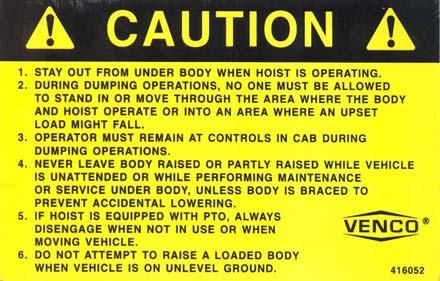
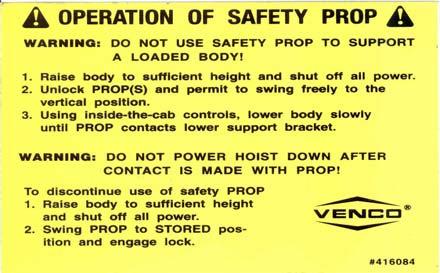
4 Included with your Venco hoist are two (2) sets of warning and caution decals. These decals should be placed in a prominent location on each side of the truck body (roadside and curbside) so they are easily seen and readily identifiable. MANUFACTURING, INC. TITLE DATE SECTION DECAL LOCATION VC , TRL C SUPERCEDES B H


5
6
7
8
9
10
11
12 HOIST MOUNTING INSTRUCTIONS Refer to drawings , , or (on the preceding pages). CAUTION If the distance between the centers of the rear axle and the rear hinge assembly exceeds 38", additional reinforcement of the truck frame is necessary. A. Mark the location for the rear hinge. Ideally this location will be immediately behind a truck cross member approximately 34" behind the center of the rear axle on a single axle truck. B. Cut a 90 slot in each side of the frame as shown in Figure 2. C. Position the angle iron frame of the rear hinge assembly in the truck frame cut outs. Make sure the rear hinge assembly is properly positioned on the truck frame. Weld all around truck frame rear hinge assembly joint (both sides). See installation drawing on the following page for information regarding the mounting of the rear hinge brackets to the body. Figure 2 - Frame Modification and Rear Hinge Attachment D. Locate the hoist on the truck frame, making sure to center and square the hoist to the truck frame. The VC Hoist is designed to rest on the truck frame. A section of the hoist extends below the truck frame level. Therefore, the hoist may have to be moved slightly forward or backward to avoid frame crossmembers. The distance between the rear hinge assembly center and the hoist center is referred to as the "M" dimension. The tables on drawings , , and provide the dump angles associated with various "M" dimensions. Note: Moving the hoist along the truck frame will affect the hoist's performance. A forward movement decreases dump angle and increases capacity. A backward movement increases dump angle and decreases capacity. MANUFACTURING, INC. TITLE DATE SECTION MOUNTING INSTR. VC VC B SUPERCEDES A H
13 BODY 6628 ONLY: WELD PLATE (FURNISHED) TO INSIDE BODY RAIL AND TO HINGE ASSY TUBE REAR HINGE BRACKET WELD HINGE ASSY TUBE TRUCK FRAME (CHASSIS) MANUFACTURING, INC. TITLE REAR HINGE TO BED MTG. INSTR. VC VC 6628 DATE A SUPERSEDES SECTION H
14 HOIST MOUNTING INSTRUCTIONS (Continued) E. After the hoist is positioned, place the mounting angles (Figure 4) under each side of the hoist saddle and against the truck frame. Clamp securely in place. Drill though the frame (17/32") and install the mounting angle with three (3) 1/2" x 1-1/2" Grade 8 hex head cap screws, lock washers, and hex nuts (both sides). NOTE: The hoist mounting bracket must sit flush on the truck frame. If rivet head interference is encountered, use a filler block or countersink clearance holes in the bottom of the hoist saddle. Do not weld the hoist mounting bracket to the truck frame. This may void the truck warranty. F. Weld each end of the hoist saddle to its mounting angle as shown in Figure 4. Note the welding symbols. Do not weld to the truck frame. Figure 4 - Mounting Angle Assembly MANUFACTURING, INC. TITLE DATE SECTION MOUNTING INSTR. VC VC A SUPERCEDES H
15 HOIST MOUNTING INSTRUCTIONS (Continued) G. Install the PTO pump per the following instructions and per the pump manufacturer's instructions. 1. See Figure 5. Position and bolt each pump bracket to the pump and secure with the 3/8 x 1-1/4" bolts and hex nuts (VC-520 requires only 2 pump brackets). 2. Position the pump assembly with brackets and securely clamp to the frame on the same side that the transmission mounted PTO shaft is located. Note: Position the pump brackets as high on the truck frame as possible when mounting the pump. 3. Two (2) 17/32" holes need to be drilled in the pump brackets and truck frame (Figure 5). Mark the hole locations as close to the truck frame flanges as possible. Drill 17/32" holes and install the 1/2" x 1-1/2" hex head cap screws with lockwashers and hex nuts. Figure 5 - Pump Installation MANUFACTURING, INC. TITLE DATE SECTION MOUNTING INSTR. VC VC A SUPERCEDES H
16 HOIST MOUNTING INSTRUCTIONS (Continued) 4. Install the truck PTO assembly using the manufacturer's instructions. 5. Determine the exact length "L" of the drive shaft (Figure 6). The drive shaft should be kept as short and level as possible. 6. Cut the 7/8" square drive shaft to the length that was determined in the previous steps. 7. The supplied U-joint (with the 1" round x 7/8" square slip yoke) fits on the pump drive shaft. The U-joint for the PTO is not furnished. 8. Trial fit each U-joint to the hex drive shaft and trial fit the drive shaft assembly to the pump and PTO. At this point, mark the set screw locations of the PTO U-joint on the square drive shaft. Disassemble the drive shaft assembly and countersink the drive shaft at the marked locations. 9. Assemble each U-joint to the hex drive shaft and install the drive shaft assembly. After installing, secure the PTO U-joint to the drive shaft using 3/8" x 5/8" drilled hex head set screw (furnished). Safety wire all (3) screws to insure that they do not loosen. 10. For additional pump and drive shaft mounting instructions, refer to the manufacturer's instructions included with the pump. Refer to Figures 6 and Dwg Figure 6 - Drive Shaft Assembly H. Install hydraulic hoses per the following instructions: 1. 7' (or 7'-10") hose(s) installation - Connect one end of the hose to the front pump port (low pressure). Connect the other end of the hose to the rod end of the hoist cylinder (Figure 5). 2. 5' hose(s) installation - Connect one end of the hose to the rear pump port (high pressure). Connect the other end of the hose to the base end of the hoist cylinder (Figure 5). MANUFACTURING, INC. TITLE DATE SECTION MOUNTING INSTR. VC VC D SUPERCEDES C H
17 HOIST MOUNTING INSTRUCTIONS (Continued) I. Position and secure the filler strips (liner or sleeper) to the truck frame (Figure 4). The VC 520 and VC 620 require a minimum of 7-1/2" clearance above the truck frame. The VC 628 requires a minimum of 8" clearance above the truck frame. The VC 5520 and VC 6620 require a minimum of 8-1/2" clearance above the truck frame. The VC 6628 requires a minimum of 10-1/2" clearance above the truck frame. Example: Assuming that a 7-1/2" clearance is required and 5" long beams are on the truck body, a liner of at least 2-1/2" net will be required to obtain the minimum clearance required to mount the hoist. 5" + 2-1/2" = 7-1/2" min. J. Position the body longitudinals (long beams) onto the truck frame. Note: At least 2" are required for clearance between the cab and closest point on the truck body. K. Place the rear hinge brackets in the vertical position (Figure 2). Weld and/or bolt the brackets to the longitudinals. If bolted, mark and drill each bracket four (4) places (17/32" holes) and secure the brackets to the longitudinals using eight (8) 1/2"-13 x 1-1/2" Grade 8 hex head cap screws, eight (8) 1/2" lockwashers, and eight (8) 1/2"-13 hex nuts. L. Refer to Drawing on the following page. Make sure that the dump body longitudinals are resting flush on the top of the spacers (which are welded to the lifting angles). Weld the top of both lifting angles (the vertical "leg") to the top flanges of the body longitudinals - a reinforcement plate may be required to fill the space between the lifting angles and body longitudinals. Weld all around the lifting angles, body longitudinals, spacers, and reinforcement plates (if used). Be sure that your installation follows the method shown on the following page - Drawing Note: Step "L" (above) is a critical installation procedure that must be carefully followed to ensure a successful hoist installation. Deviation from the suggested installation method may result in damage to the hoist. MANUFACTURING, INC. TITLE DATE SECTION MOUNTING INSTR. VC VC SUPERCEDES H
18
19
20
21 DIRECTIONAL PUMP CONFIGURATION FOR VC416 - VC620 BI-ROTATIONAL PUMP CONFIGURATION FOR VC628 & UP PUMP P/N PUMP P/N NOTE: ARROW ON PUMP HOUSING INDICATES ROTATION DIRECTION FAILURE TO MATCH PTO ROTATION WITH PUMP ROTATION WILL RESULT IN PUMP FAILURE. NOTE: FOR BI-ROTATIONAL PUMP MOUNTING AND HOSE CONNECTION INFORMATION, SEE DRAWING Model VC416 VC516 VC520 VC620 VC628 VC5520 VC6620 VC6628 Control Cable & Console Up Hose Curved Straight (2) Down Hose (2) (2) High Pressure Hose Suction Hose F Pump/Valve/Tank (9 QUART) (21 QUART) Pump (Only) Mounting/Spline Information SAE "A" 2 BOLT MOUNTING FLANGE, SAE "B" 2 BOLT MOUNTING FLANGE, 5/8"-9 SPLINE SHAFT, CCW ROTATION 7/8"-13 SPLINE SHAFT MANUFACTURING, INC. TITLE DATE SECTION SPLIT PUMP VC 416/516, VC C SUPERCEDES B H
22
23
24
25 HOIST MAINTENANCE AND OPERATION INSTRUCTIONS A. Hoist Unit Lubrication 1. PTO Driven Pump - Tighten and grease (with high quality commercial grade grease) the lube fittings located in the PTO drive shaft assembly. 2. Lubricate all grease fittings on the hoist unit. 3. Lubricate the rear hinge assembly. 4. The hoist system should be serviced at the same time the truck is serviced, and sooner if the hoist unit is performing heavy duty service. 5. Pump Reservoir - Shall be filled with the recommended oil per the manufacturer's instructions. Periodically check the hydraulic fluid and change when the truck engine oil is changed. B. PTO Pump Operation With the hoist and body completely installed, cycle the hoist several times to purge the hydraulic system of air. Operate the hoist system per the instructions in this manual and per the PTO manufacturer's instructions. WARNING Do not operate the pump at more than 1000 RPM. Severe hoist system damage could result. The PTO speed to engine speed is governed by the gear ratio of the PTO drive installed in the truck transmission. CAUTION For long service and safety from VC Hoists, it is important that the following procedure be followed each time the hoist is operated: 1. Engage the PTO from the truck cab and adjust the engine speed to obtain the correct PTO and lift speed desired. 2. Pull the pump knob out. This will cause the hoist to raise. Refer to Drawing When the hoist has reached its maximum capacity, the pump will bypass through the relief valve. To prevent the pump from bypassing, push the pump knob to the center/middle position. Whenever the pump knob is centered, the hoist will stop moving and hold its position. CAUTION Do not allow the pump to bypass for long periods of time, as this will put stress on the hydraulic and electrical systems of the hoist. 4. To lower the hoist, push the pump knob in. NOTE The Venco Hoists powered by PTO drive pumps must be "powered down". Failure to "power down" will cause the reservoir to overflow. 5. To lock the hoist against the truck frame when it is in the down position, push the pump knob in. When the pump bypasses, place the knob in the center "hold" position. 6. Disengage PTO from transmission per the manufacturer's instructions. WARNING Do not drive the truck without first disengaging the PTO drive shaft. Failure to disengage the PTO drive shaft may result in severe damage to the pump and pump drive unit. MANUFACTURING, INC. TITLE DATE SECTION MAINT. & OPER. INSTR. VC VC A SUPERCEDES H
26
27 BODY PROP USE AND WARNINGS D. Body prop(s): Federal Regulation , Paragraph 10, requires the use of a body prop. Accordingly, all Venco Hoist Units will have included as a standard item a body prop (safety strut). See Paragraphs D.1. & D.2. below. WARNING Do not place arms, hands, or any part of the body between the truck longitudinals (long beams) or moving parts to pull the body prop release/locking pin Do not use the body prop(s) to support a loaded truck body. Body prop(s) should be free swinging to a vertical position after the locking pin is released. Read operation of safety strut and caution labels before operating the hoist. 1. The body prop is designed for use only when the truck body is empty. The purpose of the body prop is to provide a safety strut for use when maintenance or inspection are performed on an unloaded truck body in the raised position. 2. One (1) body prop shall be furnished for truck bodies up to and including 15 feet. For bodies longer than 15 feet in length, two (2) body props should be used. Note: For all dump bodies two (2) body props are required. 3. On models equipped with a spring-loaded release pin, use a suitable tool to pull out the release pin to release the body prop from the hoist frame. This will release the body prop allowing it to swing downward to a vertical position. 4. Make sure that the body prop is aligned with the body prop foot rest (the body prop will be in a vertical position), then allow the truck body to move downward until the body prop is seated in the foot rest. Note: Do not power down after making contact with body prop foot rest. 5. To disengage the body prop, raise the truck body until the body prop swings freely away from the foot pad. Using a suitable tool, place the tool in a leverage position on the body prop and propel sharply to the left and upward (or to the right and upward) so that the locking pin can be compressed and seated in the locking pin hole. Make certain the body prop is latched securely before the hoist is operated. WARNING Use care when reseating the body prop(s) in the locked position. MANUFACTURING, INC. TITLE DATE SECTION BODY PROP INSTR. VC VC C SUPERCEDES B H
28
29
30
31
32 TRUCK FRAME GROUNDING STRAP #4 GAGE BLACK MANUFACTURING, INC. TITLE DATE SECTION ED POWER UNIT VC416/516, VC520/ D SUPERCEDES C
33 GROUNDING STRAP #4 GAGE BLACK M WITH MONARCH PUSH BUTTON CONTROL TRUCK FRAME NOTE: ENERGIZING 'G' COIL SENDS FLOW TO 'C1' PORT (HOIST UP) ENERGIZING 'R' COIL SENDS FLOW TO 'C2' PORT (HOIST DOWN) MANUFACTURING, INC. TITLE DATE SECTION M ED POWER UNIT VC416/516, VC520/ F SUPERCEDES E
34 MANUFACTURING, INC. TITLE WILLIAMS PTO WARNING - DATE SUPERCEDES - SECTION H
35 MANUFACTURING, INC. TITLE DATE SECTION REPLACEMENT PARTS VC C SUPERCEDES B H
36 VC 628 PD REPLACEMENT PARTS LIST ITEM QTY PART NUMBER DESCRIPTION SPRING - 11/16" O.D. x 1-3/4" LONG * CAUTION - STAND CLEAR DECAL * MOUNTING BRACKET - PUMP ROLL PIN - 5/32" DIA x 1" LONG COTTER PIN - 1/4" DIA x 3" LONG /8 X 3-1/2 X CLEVIS PIN ASSEMBLY * CAUTION - INSTRUCTIONS DECAL LOCKING PIN - PROP * SAFETY PROP DECAL LOWER PIVOT SHAFT - CYLINDER HINGE ASSEMBLY * HYDRAULIC HOSE - 3/8" x 5' * HYDRAULIC P.T.O. PUMP * INSTALLATION INSTRUCTIONS HYDRAULIC CYLINDER SCISSORS ASSEMBLY * HYDRAULIC HOSE - 3/8" x 7'-10" *ITEM NOT SHOWN ON DRAWING REPLACEMENT PARTS DWG REF NOTE: PIN FOR MULTI-PIECE HINGE IS MANUFACTURING, INC. TITLE REPL. PARTS LIST VC 628 PD DATE D SUPERCEDES C SECTION H

37 MANUFACTURING, INC. TITLE DATE SECTION REPLACEMENT PARTS VC 5520/ A SUPERCEDES H

38 * * * VC 5520 / VC 6620 REPLACEMENT PARTS LIST ITEM QTY VC 5520 VC 6620 DESCRIPTION CYLINDER - 5" OR 6" BORE x 20" STROKE LOWER CYLINDER PIVOT SHAFT SCISSORS ASSEMBLY PTO PUMP REAR HINGE ASSEMBLY MOUNTING ANGLE HYDRAULIC HOSE - 3/8" x 5 FT HYDRAULIC HOSE - 3/8" x 7 FT COTTER PIN - 1/4" X 3" /8 X 3-1/2 CLEVIS PIN ASSEMBLY BODY PROP ADJUSTABLE CLIP *ITEM NOT SHOWN ON DRAWING NOTE: SHAFT FOR MULTI-PIECE HINGE IS MANUFACTURING, INC. CINCINNATI, OHIO TITLE REPL. PARTS LIST VC 5520 / 6620 DATE E SUPERCEDES D SECTION H
39
40
41
42
TABLE OF CONTENTS VC 620 / 628 / 5520 / 6620 / 6628 MANUAL TABLE OF CONTENTS F VC VC 6628 PAGE DESCRIPTION REF. NO.
 TABLE OF CONTENTS VC 620 / 628 / 5520 / 6620 / 6628 MANUAL PAGE DESCRIPTION REF. NO. 1 READ THIS FIRST... 416733 2 IMPORTANT WARNING... 416086 3 WARNING AND CAUTION DECALS... 416128 4 VC 620 CAPACITIES...
PAGE DESCRIPTION REF. NO.
 TABLE OF CONTENTS VC 620 MANUAL PAGE DESCRIPTION REF. NO. 1 READ THIS FIRST... 416733 2 IMPORTANT WARNING... 416086 3 WARNING AND CAUTION DECAL LOCATIONS... 416128 4 DECAL DRAWINGS & LIST... 628820 5 VC
TABLE OF CONTENTS VC 620 W/ LINKAGE BODY PROP MANUAL TABLE OF CONTENTS VC 620 W/ LINK. PROP
 TABLE OF CONTENTS VC 620 W/ LINKAGE BODY PROP MANUAL PAGE DESCRIPTION REF. NO. 1 READ THIS FIRST... 416733 2 IMPORTANT WARNING...416086 3 WARNING AND CAUTION DECAL LOCATIONS... 416850 4 DECAL DRAWINGS
PAGE DESCRIPTION REF. NO.
 TABLE OF CONTENTS VC 416 / 516 MANUAL PAGE DESCRIPTION REF. NO. 1 READ THIS FIRST... 416723 2 IMPORTANT WARNING... 416272 3 BODY PROP AND WARNING / CAUTION DECALS... 416288 4 DECAL LOCATIONS... 416128
PAGE DESCRIPTION REF. NO.
 TABLE OF CONTENTS VC 416 / 516 MANUAL PAGE DESCRIPTION REF. NO. 1 READ THIS FIRST... 416723 2 IMPORTANT WARNING... 416272 3 BODY PROP AND WARNING / CAUTION DECALS... 416288 4 DECAL LOCATIONS... 416128
PAGE DESCRIPTION REF. NO.
 TABLE OF CONTENTS VC 416 / 516 MANUAL PAGE DESCRIPTION REF. NO. 1 READ THIS FIRST... 416733 2 IMPORTANT WARNING... 416272 3 BODY PROP AND WARNING / CAUTION DECALS... 416288 4 DECAL LOCATIONS... 416128
LR-416, LR-165, LR-25 INSTALLATION AND OPERATION MANUAL
 RUGBY MANUFACTURING CO. INDUSTRIAL PARK 515 1st STREET NE RUGBY, NORTH DAKOTA 58368 03 5753 LR-416, LR-165, LR-25 INSTALLATION AND OPERATION MANUAL To Be Filled In By Installer Hoist Installed: Hoist Serial
LR-26B, LR-27B, LR-28A, or LR-623 INSTALLATION AND OWNER'S MANUAL
 INDUSTRIAL PARK 515 1ST STREET NORTH EAST RUGBY, ND 58368 03 5804 LR-26B, LR-27B, LR-28A, or LR-623 INSTALLATION AND OWNER'S MANUAL Hoist Installed: Hoist Serial #: To Be Filled In By Installer Pump Installation
MODEL LR-2066 & LR-2866A HOIST INSTALLATION AND OPERATION MANUAL
 TRUCK BODIES & EQUIPMENT INTERNATIONAL, Inc. Website: www.rugbymfg.com E-mail: sales@rugbymfg.com Phone: 1-800-869-9162 03 5839 MODEL LR-2066 & LR-2866A HOIST INSTALLATION AND OPERATION MANUAL Hoist Serial
Operating & Maintenance
 TL & C SERIES Operating & Maintenance A B C D E F TO RAISE HOIST 1. Start Engine in neutral 2. Depress the clutch and engage the P.T.O. 3. Release the clutch and open the hydraulic valve. If the pump squeals,
CRYSTEEL S HOIST. this manual must be included with the vehicle after completing the installation.
 Website: www.tbei.com E-mail: sales@tbei.com CRYSTEEL S STINGRAY HOIST this manual must be included with the vehicle after completing the installation. Web Site E-Mail Phone (507) 726-2728 www.crysteel.com
BUILD YOUR OWN TRUCK HOIST ASSEMBLY AND MOUNTING INSTRUCTIONS FOR TRUCK HOIST (SINGLE LEVER) ITEM #
 ITEM #") 1 of 9 481 Panet Road Winnipeg, MB R2C 2Z1 BUILD YOUR OWN TRUCK HOIST ASSEMBLY AND MOUNTING INSTRUCTIONS FOR TRUCK HOIST (SINGLE LEVER) ITEM #1561075 TRUCK HOIST 7 TON (SINGLE LEVER) ITEM # 1200188 1.
1 of 9 481 Panet Road Winnipeg, MB R2C 2Z1 BUILD YOUR OWN TRUCK HOIST ASSEMBLY AND MOUNTING INSTRUCTIONS FOR TRUCK HOIST (SINGLE LEVER) ITEM #1561075 TRUCK HOIST 7 TON (SINGLE LEVER) ITEM # 1200188 1.
LR-3510 Install and Operation Manual
 RUGBY MANUFACTURING CO. INDUSTRIAL PARK 515 1st St. NE. RUGBY, NORTH DAKOTA 58368 03 6048 Install and Operation Manual LATEST EDITION: 1st (January 4, 2001) FIRST EDITION: January 4, 2001 Page 2 of 9 WARNINGS:
Website: ELIMINATOR MD. (701) (800)
 (800)") Website: www.tbei.com E-mail: sales@tbei.com ELIMINATOR MD www.rugbymfg.com sales@rugbymfg.com (701) 776-5722 (800) 533-0494 1228633 1 DATE PURCHASED BODY SERIAL NUMBER HOIST SERIAL NUMBER CYLINDER SERIAL
Website: www.tbei.com E-mail: sales@tbei.com ELIMINATOR MD www.rugbymfg.com sales@rugbymfg.com (701) 776-5722 (800) 533-0494 1228633 1 DATE PURCHASED BODY SERIAL NUMBER HOIST SERIAL NUMBER CYLINDER SERIAL
Rugby Manufacturing SR-Series Hoist Manual. Preface INSTALLATION & OPERATION MANUAL
 Preface INSTALLATION & OPERATION MANUAL INTRODUCTION IMPORTANT!! Read this manual thoroughly prior to installation and operation. This manual outlines the installation and operation of an SR-series hoist
AN AFFILIATE OF. The Godwin Group 200 CHAMPION DRIVE DUNN, N.C (910) FAX: (910) CONVERSION HOIST
 FAX: (910) CONVERSION HOIST") CHAMPION Hoist and Equipment AN AFFILIATE OF The Godwin Group 200 CHAMPION DRIVE DUNN, N.C. 28334 (910) 897-4995 FAX: (910) 897-7306 CONVERSION HOIST Operation & Installation Manual Notice: This manual
CHAMPION Hoist and Equipment AN AFFILIATE OF The Godwin Group 200 CHAMPION DRIVE DUNN, N.C. 28334 (910) 897-4995 FAX: (910) 897-7306 CONVERSION HOIST Operation & Installation Manual Notice: This manual
INSTALLATION INSTRUCTIONS
 TM WEIGHTLIFTER Tailgates By THIEMAN TWL 125, 16, 20 INSTALLATION INSTRUCTIONS! IMPORTANT! KEEP IN VEHICLE! PLEASE READ AND UNDERSTAND THE CONTENTS OF THIS MANUAL BEFORE OPERATING THE EQUIPMENT. NTEA T
MARATHON TELESCOPIC HOIST
 Website: www.tbei.com E-mail: sales@tbei.com CRYSTEEL S MARATHON TELESCOPIC HOIST this manual must be included with the vehicle after completing the installation. Web Site E-Mail Phone (507) 726-2728 www.crysteel.com
Rugby Manufacturing TB-8/10/12/14 Hoist Manual. Preface INSTALLATION & OPERATION MANUAL
 Preface INSTALLATION & OPERATION MANUAL INTRODUCTION IMPORTANT!! Read this manual thoroughly prior to installation and operation. This manual outlines the installation and operation of a TB-Series hoist
<THESE INSTRUCTIONS MUST BE GIVEN TO THE END USER> B&W Trailer Hitches 1216 Hawaii Road / PO Box 186 Humboldt, KS P: F:
 B&W Trailer Hitches 26 Hawaii Road / PO Box 86 Humboldt, KS 6678 P:620.73.366 F:620.869.903 RAM OEM Mount System Installation Instructions 25,000 LBS.
INSTRUCTION MANUAL 16K - Fifth Wheel Hitch
 You can take it with you. INSTRUCTION MANUAL 16K - Fifth Wheel Hitch Product No. 30047 DEALER/INSTALLER: END USER: (1) Provide this Manual to end user. (2) Physically demonstrate hitching and unhitching
HR-540/HR-550 HOIST Installation & Operation Manual
 Website: www.tbei.com E-mail: sales@tbei.com Phone: 1-800-869-9162 Rugby 1-800-255-4345 DuraClass 1-800-533-0494 Crysteel HR-540/HR-550 HOIST Installation & Operation Manual To Be Filled In By Installer
<THESE INSTRUCTIONS MUST BE GIVEN TO THE END USER> B&W Trailer Hitches 1216 Hawaii Road / PO Box 186 Humboldt, KS P: F:
 B&W Trailer Hitches 26 Hawaii Road / PO Box 86 Humboldt, KS 66748 P:620.473.3664 F:620.869.903 Ford OEM Mount System Installation Instructions 20,000
CHAMPION. Hoist and EquipmentGodwinTheGrouOperation & Installation poperation Manual 5530DM UNDERBODY HOIST
 CHAMPION GodwinTheGrouOperation & Installation poperation Manual 5530DM UNDERBODY HOIST CHAMPION HOIST & EQUIPMENT 200 Champion Drive Dunn, N.C. 28334 800-649-4995 3/2009 2 UNDERBODY HOIST Table of Contents
MODEL TB-8, TB-10, TB-12, & TB-14 TRAILER HOIST INSTALLATION AND OPERATION MANUAL
 TRUCK BODIES & EQUIPMENT INTERNATIONAL, Inc. Website: www.tbei.com E-mail: sales@tbei.com Phone: 1-800-869-9162 1-800-533-0494 090001 MODEL TB-8, TB-10, TB-12, & TB-14 TRAILER HOIST INSTALLATION AND OPERATION
<THESE INSTRUCTIONS MUST BE GIVEN TO THE END USER> BASE BOLT BAG (RVB3500) ITEM DESCRIPTION QTY. 1 2 " X 1 1 2" Hex Cap Screws 16
 ITEM DESCRIPTION QTY. 1 2 X 1 1 2 Hex Cap Screws 16") B&W Trailer Hitches 1216 Hawaii Rd / PO Box 186 Humboldt, KS 66748 P:620.473.3664 F:620.869.9031 Companion Hitch Installation Instructions 20,000 LBS.
B&W Trailer Hitches 1216 Hawaii Rd / PO Box 186 Humboldt, KS 66748 P:620.473.3664 F:620.869.9031 Companion Hitch Installation Instructions 20,000 LBS.
RIGID LIFT INSTALLATION & OPERATION MANUAL MODELS: RL-B10 THRU RL-L125
 RIGID LIFT INSTALLATION & OPERATION MANUAL MODELS: RL-B10 THRU RL-L125 THIS MANUAL IS TO BE USED IN CONJUNCTION WITH THE APPROPRIATE PUMP INSTALLATION MANUAL AND HOIST PARTS LIST. IMPORTANT FAILURE TO
<THESE INSTRUCTIONS MUST BE GIVEN TO THE END USER> 1 2 " X 1 1 2" Hex Cap Screws " Split Lock Washers " Threaded block 4
 B&W Trailer Hitches 1216 Hawaii Rd / PO Box 186 Humboldt, KS 66748 P:620.473.3664 F:620.473.3766 Companion Hitch Installation Instructions 20,000 LBS.
<THESE INSTRUCTIONS MUST BE GIVEN TO THE END USER> B&W Trailer Hitches 1216 Hawaii Road / PO Box 186 Humboldt, KS P: F:
 B&W Trailer Hitches 26 Hawaii Road / PO Box 86 Humboldt, KS 6678 P:620.73.366 F:620.869.903 Ford OEM Mount System Installation Instructions 20,000 LBS.
HR-520 HOIST. Installation & Operation Manual. To Be Filled In By Installer. Pump Installation And Operation Manual#: In Service Date: Dealer:
 Website: www.tbei.com E-mail: sales@tbei.com Phone: 1-800-869-9162 Rugby 1-800-255-4345 DuraClass 1-800-533-0494 Crysteel HR-520 HOIST Installation & Operation Manual To Be Filled In By Installer Hoist
<THESE INSTRUCTIONS MUST BE GIVEN TO THE END USER> B&W
 B&W Trailer Hitches 26 Hawaii Road / PO Box 86 Humboldt, KS 6678 P:620.73.366 F:620.869.903 GM Puck Mount System Installation Instructions 20,000 LBS.
MODEL NO & UP MODEL NO & UP MODEL NO & UP MODEL NO & UP
 MODEL NO. -900 & UP MODEL NO. 00-900 & UP MODEL NO. 0-900 & UP MODEL NO. 0-900 & UP SKID SPRAYER FORM NO. 99-055 REV. B SET-UP AND PARTS LIST Refer to the illustrated Parts List for the details of parts
Technical Support Line: (952) Hanover Ave. Lakeville, MN
 Hanover Ave. Lakeville, MN") Technical Support Line: (952) 985-5675 Email: Sales@QA1.net 21730 Hanover Ave. Lakeville, MN 55044 www.qa1.net INSTALLATION INSTRUCTIONS QA1 1967-1979 Mopar A-Body Rear 6 link Conversion System QA1 p/n
Technical Support Line: (952) 985-5675 Email: Sales@QA1.net 21730 Hanover Ave. Lakeville, MN 55044 www.qa1.net INSTALLATION INSTRUCTIONS QA1 1967-1979 Mopar A-Body Rear 6 link Conversion System QA1 p/n
DIRECT MOUNT PUMP INSTALLATION AND OPERATION MANUAL (Valve/Reservoir: W15-8CR-21 QT Pump: GP2041)
") TRUCK BODIES & EQUIPMENT INTERNATIONAL, Inc. Website: www.tbei.com E-mail: sales@tbei.com Phone: 1-800-869-9162 Rugby 1-800-533-0494 Crysteel 1-800-255-4345 Heil DIRECT MOUNT PUMP INSTALLATION AND OPERATION
TRUCK BODIES & EQUIPMENT INTERNATIONAL, Inc. Website: www.tbei.com E-mail: sales@tbei.com Phone: 1-800-869-9162 Rugby 1-800-533-0494 Crysteel 1-800-255-4345 Heil DIRECT MOUNT PUMP INSTALLATION AND OPERATION
WEAVER JACK CORP. MASTER PARTS PRICE & IDENTIFICATION LIST. (517) Fax (517) MINIMUM BILLING $20.00
 Fax (517) MINIMUM BILLING $20.00") EFFECTIVE JULY 1, 2014 WEAVER JACK CORP. MASTER PARTS PRICE & IDENTIFICATION LIST (517) 263-6500 Fax (517) 263-2810 MINIMUM BILLING $20.00 THIS PRICE LIST SUPERSEDES ALL PREVIOUS PARTS PRICE LISTS (Prices
EFFECTIVE JULY 1, 2014 WEAVER JACK CORP. MASTER PARTS PRICE & IDENTIFICATION LIST (517) 263-6500 Fax (517) 263-2810 MINIMUM BILLING $20.00 THIS PRICE LIST SUPERSEDES ALL PREVIOUS PARTS PRICE LISTS (Prices
Trailer Parts. Brake Components. Axle Components. Suspensions. Lights & Electrical. Wheels & Tires. Loading Ramps. Couplers & Safety Chains
 Trailer Parts Brake Components Axle Components Suspensions Lights & Electrical Wheels & Tires Loading Ramps Couplers & Safety Chains Trailer Jacks Fenders Dump Trailer Parts Tilt SST Parts Decal Kits Brake
Rugby Manufacturing Direct Mount Unit Manual
 Preface INSTALLATION & OPERATION MANUAL INTRODUCTION IMPORTANT!! Read this manual thoroughly prior to installation and operation. This manual outlines the installation and operation of a Direct Mount unit
One- Touch Installation Instructions
 One- Touch Installation Instructions 1 1 Height Adjustable Pivot w/ screws 9 Upper Work Surface 2 Rail Mount Knobs 10 Back Cover 3 Transformer 11 Center Pivot w/ screws 4 Support Legs 12 Left Monitor Arm
INSTRUCTION MANUAL Kwik Slide
 INSTRUCTION MANUAL Kwik Slide FOR USE WITH 30048 DEALER/INSTALLER: (1) Provide this Manual to end user. (2) Physically demonstrate sliding procedures in this Manual to end user. (3) Have end user demonstrate
Parts Manual Rev. A RZT48 /
 115 91 36-2 Rev. A Parts Manual RZT48 / 96 62001-00 Please read the operator manual carefully and make sure you understand the instructions before using the machine. Gasoline containing a maximum of 10%
MODEL NO & UP MODEL NO & UP MODEL NO & UP MODEL NO & UP MODEL NO.
 9-0688 MODEL NO. 00-800 & UP MODEL NO. 0-800 & UP MODEL NO. 5-800 & UP MODEL NO. -800 & UP MODEL NO. 0-800 & UP SKID SPRAYER with the Centrifugal Pump FORM NO. 95-9095 SET-UP AND PARTS CATALOG SAFETY AND
SECTION TWO MOUNTING INSTRUCTIONS
 SECTION TWO MOUNTING INSTRUCTIONS TRUCK-MOUNTED CONVEYORS FBR-FIBERGLASS SERIES TURNTABLES- RTH 3000, RTH 4000, RTH 6000 GENERAL 2-1 Parts Supplied by CM 2-1 Parts to be Supplied by the Customer or Installer
HAND THROTTLE KIT For Workman 3000 Series
 FORM NO. 7 6 MODEL NO. 0746 INSTALLATION INSTRUCTIONS HAND THROTTLE KIT For Workman 000 Series. Position vehicle on a clean, level surface, stop engine, engage parking brake and remove key from ignition
DUMP BODY SPREADERS INSTALLATION INSTRUCTIONS
 DUMP BODY SPREADERS INSTALLATION INSTRUCTIONS (Includes PS350 & PS400) EFFECTIVE 09/2011 Revision A 1330 76TH AVE SW CEDAR RAPIDS, IA 52404-7052 PHONE (319) 363-8281 FAX (319) 286-3350 www.highwayequipment.com
Parts Manual Rev. B RZT48 /
 115 91 36-2 Rev. B Parts Manual RZT48 / 96 62001-00 Please read the operator manual carefully and make sure you understand the instructions before using the machine. Gasoline containing a maximum of 10%
DIRECT MOUNT PUMP INSTALLATION AND OPERATION MANUAL (Valve/Reservoir: M-8CR06-9RQT. Pump: GP916CCW)
") TRUCK BODIES & EQUIPMENT INTERNATIONAL, Inc. Website: www.tbei.com E-mail: sales@tbei.com Phone: 1-800-869-9162 Rugby 1-800-255-4345 Heil 1-800-533-0494 Crysteel DIRECT MOUNT PUMP INSTALLATION AND OPERATION
TRUCK BODIES & EQUIPMENT INTERNATIONAL, Inc. Website: www.tbei.com E-mail: sales@tbei.com Phone: 1-800-869-9162 Rugby 1-800-255-4345 Heil 1-800-533-0494 Crysteel DIRECT MOUNT PUMP INSTALLATION AND OPERATION
Trailer Parts. Brake Components. Axle Components. Suspensions. Lights & Electrical. Wheels & Tires. Loading Ramps. Couplers & Safety Chains
 Trailer Parts Brake Components Axle Components Suspensions Lights & Electrical Wheels & Tires Loading Ramps Couplers & Safety Chains Trailer Jacks Fenders Dump Trailer Parts Tilt SST Parts Decal Kits Brake
BUSH HOG LAND MAINTENANCE REPAIR PARTS MANUAL MODEL: 3414 SECTION: 67
 BUSH HOG LAND MAINTENANCE REPAIR S MANUAL MODEL: SECTION: 0 Griffin Ave. Selma, AL 0 () - () -00 Parts Ordering -00-0- Fax -00-- www.bushhog.com BUSH HOG/ LAND MAINTENANCE REPAIR S MANUAL July, 0 ROTARY
B&W Trailer Hitches 1216 Hawaii Road / PO Box 186 Humboldt, KS P: F: " Split Lock Washers 8
 B&W Trailer Hitches 1216 Hawaii Road / PO Box 186 Humboldt, KS 66748 P:620.473.3664 F:620.869.9031 NOTE: We recommend reading instructions before beginning the installation. Companion Slider Hitch Installation
TT-12 OWNERS MANUAL/PARTS LIST
 TOPLIFTER Tailgates By THIEMAN TT-12 OWNERS MANUAL/PARTS LIST SHOWN WITH OPTIONAL 2 PC. ALUMINUM PLATFORM! IMPORTANT! KEEP IN VEHICLE! PLEASE READ AND UNDERSTAND THE CONTENTS OF THIS MANUAL BEFORE OPERATING
REAR ENGINE RIDER 42 MOWER SERIES 22
 Parts Manual for REAR ENGINE RIDER MOWER SERIES MODELS 1BVE CONTENTS DESCRIPTION PAGE(S) DESCRIPTION PAGE(S) WHEELS- TIRES... - FRONT END, STEERING.... - MAIN CASE... - DIFFERENTIAL, R. H. FENDER... 8-9
25 Horsepower Hydrostatic Zero-Turn Commercial Riding Mower
 MMZ 2, 260 2 Horsepower Hydrostatic Zero-Turn Commercial Riding Mower ILLUSTRATED PARTS LIST " Float Cutter Deck - Figure 1 3 1 27 32 17 6 1 11 31 36 3 19 7 23 1 33 38 18 37 22 3 20 2 10 2 12 21 30 39
<THESE INSTRUCTIONS MUST BE GIVEN TO THE END USER> B&W
 B&W Trailer Hitches 1216 Hawaii Rd / PO Box 186 Humboldt, KS 66748 Turnoverball Gooseneck Hitch Installation Instructions MODEL 1314 2013 2014 RAM 3500
SL15/20-6 AND SL15/20-10 INSTALLATION INSTRUCTIONS
 STOWAWAY SideLoader Tailgates By THIEMAN SL15/20-6 AND SL15/20-10 INSTALLATION INSTRUCTIONS! IMPORTANT! KEEP IN VEHICLE! READ AND UNDERSTAND THE CONTENTS OF THIS MANUAL BEFORE OPERATING THE EQUIPMENT.
Installation Instructions Capacity 10,000 lbs. (100 Series Lift)
") Installation Instructions Capacity 10,000 lbs. (100 Series Lift) IMPORTANT Reference ANSI/ALI ALIS, Safety Requirements for Installation and Service of Automotive Lifts before installing lift. OPERATING
Installation Instructions Capacity 10,000 lbs. (100 Series Lift) IMPORTANT Reference ANSI/ALI ALIS, Safety Requirements for Installation and Service of Automotive Lifts before installing lift. OPERATING
SERVICE INSTRUCTIONS D TON
 1120 SOUTH CRYSTAL AVE * BENTON HARBOR MI PH: 269-925-7777 FAX: 269-925-6656 SERVICE INSTRUCTIONS D-51223 4 TON TO ASSEMBLE: 1. Check the handle set screw for tightness. CUSTOMER PRE-USE INSTRUCTIONS THE
INSTRUCTION MANUAL 16K - Fifth Wheel Hitch
 You can take it with you. INSTRUCTION MANUAL 16K - Fifth Wheel Hitch Product No. 30047 DEALER/INSTALLER: END USER: (1) Provide this Manual to end user. (2) Physically demonstrate hitching and unhitching
<THESE INSTRUCTIONS MUST BE GIVEN TO THE END USER> B&W
 B&W Trailer Hitches 6 Hawaii Rd / PO Box 86 Humboldt, KS 6678 P:60.7366 F:60.86.03 Turnoverball Gooseneck Hitch Installation Instructions MODEL 38 0 08
LAWN TRACTORS MANUAL CLUTCH HYDRO DRIVE SERIES "G"
 Parts Manual for LAWN TRACTORS MANUAL CLUTCH HYDRO DRIVE SERIES "G" MODEL ELT145H33GBV LT145H33GBV LT145H38GBV LT150H38GKV WLT145H38GKV McDonough, GA, 30253 U.S.A. COPYRIGHT 2006 SNAPPER PRODUCTS, INC.
ARTICEL Drywall Panel Hoist
 Operation Manual ARTICEL 50790 51289 Drywall Panel Hoist Read and follow the operating instructions and safety information before using for the first time. Technical changes reserved! Due to further developments,
LAWN TRACTORS ELECTRIC CLUTCH HYDRO DRIVE SERIES "G"
 Parts Manual for LAWN TRACTORS ELECTRIC CLUTCH HYDRO DRIVE SERIES "G" MODEL LT160H42GBV LT160H42GBV2 LT180H48GBV2 WLT160H42GBV WLT180H48GBV2 McDonough, GA, 30253 U.S.A. COPYRIGHT 2006 SNAPPER PRODUCTS,
Kinze 3000 Series Row Unit. Hydraulic Actuator Installation Instructions PN: ENG REV. A
 Kinze 3000 Series Row Unit Hydraulic Actuator PN: 2006428-ENG REV. A Installation Overview Required Parts Part Number Qty * Description 4003011 1 HYDRAULIC ACTUATOR ASSY. (INCLUDES MOUNTING HARDWARE) 4003458
B&W Trailer Hitches 1216 Hawaii Road / PO Box 186 Humboldt, KS P: F:
 B&W Trailer Hitches 1216 Hawaii Road / PO Box 186 Humboldt, KS 66748 P:620.473.3664 F:620.869.9031 NOTE: We recommend reading instructions before beginning the installation. Ford OEM Mount System Slider
10. Lower Fuselage Assembly Undercarriage
 10. Lower Fuselage Assembly Undercarriage Undercarriage 10.27 2 230399 0 Jabiru Undercarriage Configurations There are four combinations of tyres available, utilising two sets of hubs (standard and heavy
! Williams Machine & Tool 204 Plastic Lane Pump Serial No. Monticello, IA USA
 NOTICE: This manual is to remain with truck after pump unit is installed. MACHINE & TOOL Hydraulic Piston Pump Units Operating, Mounting and Safety Instructions for: Model 20 Pump Model 40 Pump Model F98
<THESE INSTRUCTIONS MUST BE GIVEN TO THE END USER> B&W Trailer Hitches 1216 Hawaii Rd / PO Box 186 Humboldt, KS P: F:
 B&W Trailer Hitches 6 Hawaii Rd / PO Box 86 Humboldt, KS 6678 P:60.7366 F:60.73766 Turnoverball Gooseneck Hitch Installation Instructions MODEL 38 0 06
B&W Trailer Hitches 1216 Hawaii Road / PO Box 186 Humboldt, KS P: F:
 B&W Trailer Hitches 1216 Hawaii Road / PO Box 186 Humboldt, KS 66748 P:620.473.3664 F:620.473.3766 NOTE: We recommend reading instructions before beginning the installation. GM OEM Mount System Slider
HEIDTS SUPERIDE IRS INSTALLATION INSTRUCTIONS INDEPENDENT REAR SUSPENSION
 HEIDTS SUPERIDE IRS INDEPENDENT REAR SUSPENSION Please read these instructions completely before starting your installation. Remember the basic rule for a successful installation: Measure Twice, Weld Once.
SPARE PARTS LIST RIDERS P525 D, , 2016
 SPARE PARTS LIST RIDERS P525 D, 967602101, 2016 CABIN P525 D, 967602101, 2016 CABIN P525 D, 967602101, 2016 Ref Part No Description Remark QTY KIT 1 501 99 86-01 DOOR 1 2 501 99 87-01 SEAL 1 3 579 86 79-01
Parts Manual Rev. A RZT54 /
 115 93 37-27 Rev. A Parts Manual RZT54 / 967 672101-00 Please read the operator manual carefully and make sure you understand the instructions before using the machine. Gasoline containing a maximum of
INSTALLATION INSTRUCTIONS
 INSTALLATION INSTRUCTIONS ----3300 W. Pontiac Way Clovis, CA 93612 toll free: 1-800-445-3767 web: www.belltech.com---- 6605-6607 FLIP KIT CHEVROLET C/K 1500 / 2500 PICK UP Thank you for being selective
Installation Instructions
 Installation Instructions 2-Post Capacity 12,000 lbs. OPERATING CONDITIONS Lift is not intended for outdoor use and has an operating ambient temperature range of 41-104 F (5-40 C) IMPORTANT Reference ANSI/ALI
250P Manure Spreader
 0P Manure Spreader Illustrated Parts Breakdown Page - Page Page Page Page Page Page Page Page Page Page Page Page Page Page - Page Page Page 0 Complete Front End PTO/Jack/Hitch Assembly Front Pulley Assembly
Model 3770 WARNING. Failure to comply with the safety information in these instructions could result in serious injury or death.
 B&W Trailer Hitches 1216 Hawaii Road / PO Box 186 Humboldt, KS 66748 P:620.473.3664 See Limited Lifetime Warranty at F:620.869.9031 bwtrailerhitches.com/warranty NOTE: We recommend reading instructions
** DO NOT EXCEED THE RECOMMENDED VEHICLE TOWING WEIGHT RATING ** DODGE RAM 1500
 10/3/2017 DODGE RAM 1500 WARNING!! BRAKE, FUEL, AND ELECTRICAL LINES MAY NEED TO BE LOOSENED OR REPOSITIONED TO PROVIDE CLEARANCE FOR NEW HARDWARE. ON SHORT BED MODELS, CHECK FOR ADEQUATE TURNING CLEARANCE
Mid-Engine Rider. Parts Manual Model Revision 00 TP LT-L
 Mid-Engine Rider Parts Manual Model 7800337 1741802 Revision 00 Rev. Date 05/2008 Table Of Contents PRODUCT COMPONENTS PAGES Steering... 4 Motion Drive... 6 Electrical System... 10 Chassis & Hood... 12
WARNING!! C-659 SUBKIT FIGURE 4
 '0-'0 DODGE / TON TRUCKS '03-' DODGE 3/ & TON TRUCKS (WILL FIT /, 3/ & TON MEGA CAB SHORT BED) WARNING!! BRAKE, FUEL, AND ELECTRICAL LINES MAY NEED TO BE LOOSENED OR REPOSITIONED TO PROVIDE CLEARANCE FOR
Parts Manual for LAWN TRACTORS MANUAL CLUTCH HYDRO DRIVE SERIES F MODELS LT145H33FBV LT145H38FBV ELT145H33FBV
 Parts Manual for LAWN TRACTORS MANUAL CLUTCH HYDRO DRIVE SERIES F MODELS LT145H33FBV LT145H38FBV ELT145H33FBV IT IS THE POLICY OF SNAPPER TO IMPROVE ITS PRODUCTS WHENEVER IT IS POSSIBLE AND PRACTICAL TO
72K850ZP PARTS MANUAL
 7 2 K 8 5 0 Z P PARTS MANUAL 72 MID-CUT GAS ENGINE OPTION SECTION 72 MID-CUT DECK ASSEMBLY 72" Mid-Cut Deck Assembly # PART NO. QTY DESCRIPTION 1 582096 1 72" MC DECK WELDMENT 2 582098 1 72" DECK CHANNEL
<THESE INSTRUCTIONS MUST BE GIVEN TO THE END USER> B&W
 B&W Trailer Hitches 1216 Hawaii Rd / PO Box 186 Humboldt, KS 66748 P:620.473664 F:620.869.9031 Turnoverball Gooseneck Hitch Installation Instructions
PAGE 1. 7/18 HJ26141 Rev 12
 PAGE 1 7/18 HJ26141 Rev 12 WARRANTY POLICY, OPERATOR MANUALS & REGISTRATION Go online to www.demco-products.com to review Demco warranty policies, operator manuals and register your Demco product. Please
TT-15 INSTALLATION INSTRUCTIONS SHOWN WITH OPTIONAL 2 PC. ALUMINUM PLATFORM AND LIGHT KIT
 TM TOPLIFTER Tailgates By THIEMAN TT-15 INSTALLATION INSTRUCTIONS SHOWN WITH OPTIONAL 2 PC. ALUMINUM PLATFORM AND LIGHT KIT! IMPORTANT! KEEP IN VEHICLE! PLEASE READ AND UNDERSTAND THE CONTENTS OF THIS
RL-D40 PARTS LIST # H USE THIS PARTS LIST FOR:
 RL-D40 PARTS LIST # 102689H USE THIS PARTS LIST FOR: Hoist Serial Number 24815 to For older hoists use the following: Parts List No. 102689E for Serial Number 17062 to 24814 Parts List No. 102689C for
Proudly built in the USA. Owner s Manual TC-502 Metro Hoist, Sub-Frame, and Dump Body
 Proudly built in the USA Owner s Manual TC-50 Metro Hoist, Sub-Frame, and Dump Body TruckCraft Corporation Chambersburg, PA -00-755-67 Copyright c 009 TruckCraft Corporation Rev. - - /7/09 I5-059 TRUCKCRAFT
CUTTER DECK. * Purchase part Shear Bolt Package to replace these parts. (4 of each per package)
") 0 0 0 0 CUTTER DECK 0 0S00 CUTTER DECK Foot Plate 00-0 Serr. Fl. Hex Nut, /- -0 Grease Fitting Frame, Cutter Deck Support (incl.,,) 00-0 Hex Locknut, Elastic Stop, /- 0 Rod, Deck Prop - L.H. 00- Serr.
0 0 0 0 CUTTER DECK 0 0S00 CUTTER DECK Foot Plate 00-0 Serr. Fl. Hex Nut, /- -0 Grease Fitting Frame, Cutter Deck Support (incl.,,) 00-0 Hex Locknut, Elastic Stop, /- 0 Rod, Deck Prop - L.H. 00- Serr.
Owner s Manual TC-515 with Reversed Hoist, Sub-Frame, Deck, & Hitch Mount
 Proudly built in the USA Owner s Manual TC-55 with Reversed Hoist, Sub-Frame, Deck, & Hitch Mount TruckCraft Corporation Chambersburg, PA -800-755-87 Copyright c 0 www.truckcraft.com TruckCraft Corporation
PERFORMANCE SUSPENSION PARTS
 PERFORMANCE SUSPENSION PARTS Introduction Air Lift Performance The purpose of this publication is to assist with the installation, maintenance and troubleshooting of this Chrysler LX, LD, LC Platform 300C,
M10/30 ILLUSTRATED PARTS LIST HERITAGE TRACTOR CODE 133E ISSUE 01/21/08. PART NO: (Rev A)
") M10/30 HERITAGE TRACTOR CODE 133E ILLUSTRATED PARTS LIST CODE SERIAL NO. 133E 280000001 ISSUE 01/21/08 1741746 PART NO: 111-2202 (Rev A) Table Of Contents PRODUCT COMPONENTS PAGES Chassis & Hood... 4
M10/30 HERITAGE TRACTOR CODE 133E ILLUSTRATED PARTS LIST CODE SERIAL NO. 133E 280000001 ISSUE 01/21/08 1741746 PART NO: 111-2202 (Rev A) Table Of Contents PRODUCT COMPONENTS PAGES Chassis & Hood... 4
Parts Manual Rev. A
 115 96 28-27 Rev. A Parts Manual Z 242F / 967 271802-00 Please read the operator manual carefully and make sure you understand the instructions before using the machine. Gasoline containing a maximum of
BUSH HOG LAND MAINTENANCE REPAIR PARTS MANUAL
 BUSH HOG LAND MAINTENANCE REPAIR PARTS MANUAL MODEL: DM7, DM8, DM9 SECTION: 43 2501 Griffin Ave. Selma, AL 36703 (334) 872-6261 (334) 874-2700 Parts Ordering 1-800-304-2836 Fax 1-800-572-1784 www.bushhog.com
TruckCraft Corporation Rev. 1/28/2016 I Table of Contents
 TruckCraft Corporation Rev. 1/28/2016 I5-05579 TRUCKCRAFT CORPORATION 5751 Molly Pitcher Hwy. S. Chambersburg, Pa. 17202 Tel. 800.375.3867 Phone 717.375.2900 Fax 717.375.2975 www.truckcraft.com "WHERE
Model 3400 ATTENTION: WARNING
 B&W Trailer Hitches 1216 Hawaii Road / PO Box 186 Humboldt, KS 66748 P:620.473.3664 F:620.473.3766 NOTE: We recommend reading instructions before beginning the installation. Companion Slider Hitch Installation
OPERATOR, PARTS AND INSTALLATION MANUAL. BX7330 AVENTA TM Tow Bar TOWING PRODUCTS DIVISION
 A V E N T A TM OPERATOR, PARTS AND INSTALLATION MANUAL BX7330 AVENTA TM Tow Bar TOWING PRODUCTS DIVISION SAFETY DO NOT INSTALL, OPERATE OR USE THIS EQUIPMENT UNTIL THE FOLLOWING OPERATING AND SAFETY INSTRUCTIONS
Premium Supply. Direct Push. Models PCK-3530-DP PCK DP PCK-530-DP. Operator s Manual and Installation Instructions
 Direct Push Models PCK-3530-DP PCK-3530-2DP PCK-530-DP Operator s Manual and Installation Instructions Premium Supply 2038 West Interstate 30 866-934-0777 Proud members of: and June 20, 2018 Table of Contents
INSTRUCTIONS AND PARTS LIST FOR Models 6-225, 6-425, 6-250, 6-450, 6-275, 6-475, 6-650, and Air Hydraulic Presses
 INSTRUCTIONS AND PARTS LIST FOR Models 6-225, 6-425, 6-250, 6-450, 6-275, 6-475, 6-650, and 6-850 Air Hydraulic Presses WARNING LABELS To the left is the safety Alert symbol. When you see these safety
TCI FastGate Shifter Installation Instructions
 151 INDUSTRIAL DRIVE ASHLAND, MISSISSIPPI 38603 http://www.tciauto.com TELEPHONE: 662-224-8972 FAX LINE: 662-224-8255 E-MAIL: tech@tciauto.com TCI 616541 FastGate Shifter Installation Instructions The
DOOR KIT P/N , APPLICATION BEFORE YOU BEGIN KIT CONTENTS. Verify accessory fitment at Polaris.com.
 DOOR KIT P/N 2882561, 2882562 APPLICATION Verify accessory fitment at Polaris.com. BEFORE YOU BEGIN Read these instructions and check to be sure all parts and tools are accounted for. Please retain these
M-ZT 61. Parts Manual. Zero Turn Mower /
 Parts Manual M-ZT 61 Zero Turn Mower / 967177008-01 Please read the operator manual carefully and make sure you understand the instructions before using the machine. When you need spare parts or support
19.02 p1 08/01 MOWER DECK, 72"
 19.02 p1 0/01 MOWER DECK, 72" 19.02 p1 0/01 MOWER DECK, 72" REF FN PART NUMBER YR/SN QTY DESCRIPTION 1 1, 2 AUB160499 From 10/9 1 CUTTER BOX Deck, Mower, 72" 1 3 AUB161157 From 01/93 1 DECK, MOWER Deck,
Parts Manual MZ5225 /
 Gasoline containing up to 10% ethanol (E10) is acceptable for use in this machine. The use of any gasoline exceeding 10% ethanol (E10) will void the product warranty. Parts Manual MZ5225 / 966690502 Please