AN AFFILIATE OF. The Godwin Group 200 CHAMPION DRIVE DUNN, N.C (910) FAX: (910) CONVERSION HOIST
|
|
|
- Patience Bruce
- 5 years ago
- Views:
Transcription
1 CHAMPION Hoist and Equipment AN AFFILIATE OF The Godwin Group 200 CHAMPION DRIVE DUNN, N.C (910) FAX: (910) CONVERSION HOIST Operation & Installation Manual Notice: This manual is to remain with truck after Hoist is installed.

2 Notes It is recommended that the Owner/Operator record the following information immediately after purchasing. So that when calling for Parts or Service, the information will be readily on hand. Dump Truck Body Model Number Serial Number Subframe Assembly Model Number Serial Number Hoist Assembly Model Number Serial Number Truck Year Make Model Truck Number July/2017 2
3 TABLE OF CONTENTS Safety Alert Symbols 4 Safety Checklist 5 Periodic Inspections 6 To Operate the Hoist 7 Power Take OFF (PTO) Pump Electric Pump Pump Rotation and Porting 8 Hydraulic Plumbing Diagram 9 Hydraulic Plumbing Diagram, Single Acting Electric Pump (PD40048) 10 Hydraulic Plumbing Diagram, Double Acting Electric Pump (PD40045) 11 Electric Pump Priming Procedure (MP50398) 12 Electric Pump Troubleshooting Procedure (MP50399) 13 Hoist Installation Procedure I, Hoist Location on Truck Chassis 14 Hoist Installation Procedure II, Bed Spacer and Rear Hinge Installation 15 Hoist Installation Procedure III, Removing Slack from Hoist and Rear Hinge 16 Hoist and Dump Body Installation Procedure 17 Safety Prop Installation CS412TRK Scissor Hoist (A12454) CS415TRK Scissor Hoist (A12337) CS515TRK Scissor Hoist (A12338) CS615TRK Scissor Hoist (A12339) Rear Hinge Assemblies (W13678 & A131274) 32 CS415LP Scissor Hoist (A12427) CS515LP Scissor Hoist (A12428) CS615LP Scissor Hoist (A12429) CS615HDLP Scissor Hoist (A12557) CS620HDLP Scissor Hoist (A12556) CS6615LP Scissor Hoist (A12552) CS6620LP Scissor Hoist (A12212) CS628LP Scissor Hoist (A12554) CS5530LP Scissor Hoist (A12553) CS6630LP Scissor Hoist (A12547) Rear Hinge Assembly (A20062) 63 Page 3
4 Attention: Befor e Oper ating, Maintaining, or Repair ing the Conver sion Hoist r ead this manual completely and refer to it continuously. Safety Alert Symbols The terms Danger, Warning, and Caution are used to indicate different levels of potential hazard to equipment and personnel. Indicates a hazardous situation which, if not avoided, will result in death or serious injury. This signal word is to be limited to the most extreme situations. Indicates a hazardous situation which, if not avoided, could result in death or serious injury. Indicates a hazardous situation which, if not avoided, could result in minor injury. Used to warn of a potential hazard to the equipment. 4

5 Safety Checklists To prevent possible death or injury to personnel and damage to the equipment, the following checklist is to be performed prior to operating and while operating the Truck and Hoist. Pre-Operation Checklist it continuously. Prior to initial operation of Truck and Hoist read this manual completely and refer to Prior to operation of Hoist read and understand all the Safety Symbols, (Cautions, Warnings, and Dangers) in this manual, identify them on the Truck and Hoist, and follow their instructions carefully. If any Safety Symbols are missing or incomplete on the Subframe, Hoist, or Dump Body order them from Godwin Manufacturing. Do not allow unauthorized personnel to operate this equipment. Do not allow personnel to ride in or on the truck body. Do not operate a loaded truck on unlevel or soft surfaces. Prior to operation of Hoist inspect to ensure that the safety props, pump/valve guard, & PTO shaft guards are in place and in good working order. Disengage the PTO drive prior to operating the truck. Moderately high PTO speeds will damage the pump and sustained high PTO speeds may cause the hydraulic oil temperature to rise high enough to damage the pump. Operational Checklist Before loading the Truck make sure that the load does not exceed the Gross Vehicle Weight (GVW) rating of vehicle or the Hoist s rated lifting capacity. Always load the Dump Body evenly from side-to-side and from front-to-rear. Prior to operating the hoist ensure the area is clear of personnel and equipment. Do not allow hoist controls and the area around them to become cluttered with tools, cans, etc. Do not operate the hoist under Power Lines. Do not raise the hoist when truck is in motion. Do not move the truck with the hoist raised. Always release tailgate latching controls prior to lifting the dump body. Always operate the hoist controls from inside the truck cab. Do not go underneath a loaded and raised truck body under ANY circumstances. Do not go underneath a truck with the engine running. Do not go underneath an unloaded raised truck body unless the safety props are properly installed. Do not leave truck unattended with truck body raised. Post Operation Checklist Do not use hands or other body parts to check for hydraulic leaks. Follow all Federal, State, and local regulation pertaining to this equipment. Keep all equipment properly maintained and serviced. 5
6 Periodic Inspections The following checklist is to be followed prior to operating and while operating the Truck and Hoist. Daily Inspection (Before Operating) Check hydraulic oil level and add more to the reservoir as needed. For PTO driven pumps use HD 32 hydraulic oil. For electric driven pumps use ATF, automatic transmission fluid. Check for any fluid leaks under truck and hoist. Make sure all components are securely fastened, such as frame/pump guard, tool box is closed, hydraulic hoses for spreader/plow properly stowed, etc. Check all lighting to be sure it is functioning properly. Check lighting on any towed equipment. Inspect hitch if towed equipment is attached and be sure safety chains are fastened. Test hydraulic functions and observe for proper operations. Check tire pressure per markings on the tires. Weekly Inspection Perform all of the above checks. Inspect all mechanical functions, i.e., hoist pivots, rear hinge pivots, single hitch, etc. Be sure they have been properly lubricated and show no signs of stress. Test Low Oil Shutdown system to be sure it is operating properly. Bi-Monthly Inspection Lubricate all hoist pivot points and rear hinge assemblies with chassis grease. Lubricate pintle hitch with chassis grease. Six Months to One Year (Depending upon usage) Change hydraulic oil filter. (1st change after 50 hours of operation.) Inspect suction strainer in oil tank. Check hydraulic oil for contamination, discoloration, signs of wear, etc. 6
7 Power Take Off (PTO) and Electric Pump Operations Disengage PTO before driving truck. PTO operation is controlled by either a cable, electric hydraulic system, or air shift system. (Refer to figure below.) To Engage PTO on Standard Transmission. The follow instructions are to be performed with the engine running at idle speed, transmission in neutral, and the park brake engaged. 1. Allow the engine to slow to idle speed, shift into neutral, and engage the park brake. 2. Depress and hold down the clutch pedal. 3. Pull PTO control out until the red PTO light illuminates. NOTE: If light does not illuminate, and PTO does not engage. Slowly release the clutch pedal while pulling on the PTO control. 4. When the PTO is engaged, slowly release the clutch pedal to supply power to the Hoist pump. 5. The pump/hoist control should be in the neutral or hold position. 6. Depress the Safety button and pull the pump/hoist control to raise the bed. 7. When bed raises to desired height push the pump/hoist controls to the center neutral or hold position this will stop bed movement up or down. 8. To lower the bed depress the Safety button and push pump/hoist control. 9. Depress clutch pedal, and push PTO control to disengage. To Engage PTO on Automatic Transmission. 1. Allow the engine to slow to idle speed, engage the park brake, and shift into a drive gear. This will stop the transmission gears from turning. 2. Shift PTO into gear, then shift transmission into neutral. This will start transmission gears turning, and in turn, put PTO into operation. Electric Pump Press and hold the appropriate button. NOTE: Pump will stop when button is released. Body Up (Pull Lever) Red Safety Button Electric Control Power U D Hold Body Down Press Red Safety and Push 7
8 PUMP ROTATION AND PORTING INPUT SHAFT REAR PORTS OPTIONAL SIDE PORT (OTHER SIDE AS WELL) SUCTION SIDE CW CCW PRESSURE SIDE CLOCKWISE ROTATION (CW) (SEE ABOVE) COUNTER-CLOCKWISE ROTATION (CCW) (SEE ABOVE) The P21 and P22 Pumps are bi-directional and offer side and rear (NPT) Porting. The pumps are shipped with the side ports plugged. To utilize side porting move the steel plugs from the side ports to the rear ports and plumb the hydraulic lines Refer to the illustration above for Port Designation based on pump rotation. Helpful Hint: To determine pump rotation, do not remove the plastic shipping plugs. Temporarily bolt pump to the mounted PTO. Start truck engine and engage PTO for approximately 3 seconds, then disengage PTO and shut-off engine. The plastic shipping plug on the pressure port should have popped out of the pump housing. 8

9 Hydraulic Plumbing Diagram 9

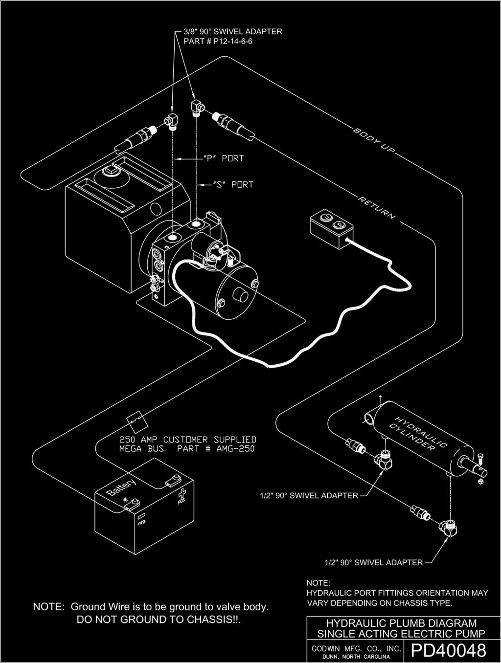
10 10
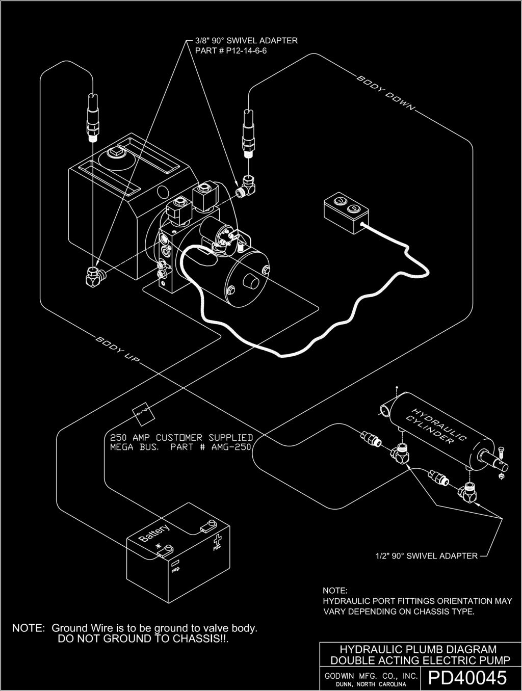
11 11
12 Electric Pump Priming Procedure Single acting (M-3519) or Double acting (M-3551) A. Be sure hoist and electric pump are completely installed and ready to safely operate. Fill electric pump reservoir with Automatic Transmission Oil to within 1 inch of top. B. Power the hoist Up using the White button the push button controller. NOTE: If hoist does not start to raise within 10 seconds, stop and check that the hydraulic lines are correctly installed. See below: Monarch 3551 (double acting, yellow) C1 port = hoist raise (white button) = 3200psi. C2 port = hoist lower (black button) = 800psi. Monarch 3519 (Single acting, orange) P port = hoist raise (white button) = 3200psi. S port = lower/vent to res (black button) = 0 psi. To prevent damage to the equipment, Do Not allow the hydraulic reservoir to run out of hydraulic, Automatic Transmission Oil. Always maintain at least a half tank of oil. C. When powering the hoist Up the first time it is imperative that the reservoir NOT run out of oil. Maintain a half tank of oil on the first lift by stopping and filling as needed. D. Check for leaks during lifting operations and check for obstructions. E. For Double Acting Pump Only - Lower the hoist by pressing the black button. NOTE: Lower the hoist 1/3 and stop for 20 seconds, repeat two more times until hoist is fully lowered. Once the hoist has fully lowered CONTINUE to hold the black button until the oil in the reservoir stops moving (turbulence), about 20 seconds. The turbulence in the reservoir during this crucial step is filling the top side (or down side) of the cylinder. This typically has to be done only upon the initial installation or when the unit has run low in oil and is being refilled. F. After steps A through E have been done fill the reservoir as needed to maintain ⅔ to ¾ full with the bed down. Helpful Hints: 1. Perform the above priming steps no more than twice in 30 minutes due to oil aerating. 2. If the reservoir overflows when lowering, the following could cause overflowing. (a) Aerated oil (b) Hoist lower line too small or obstructed (c) Wrong ports used on pump (d) extremely cold conditions. 3. Make sure the customer understands that the electric power unit (used when necessary) has the same lifting capacity but will be slower than a PTO driven unit. 4. Do not operate pump more than (2) minutes at a time or without truck engine running so as to keep a charge in battery. Electric Pump Priming Procedure Godwin Mfg. Co., Inc. Dunn, North Carolina MP
13 Electric Pump Troubleshooting Procedure Single acting (M-3519) or Double acting (M-3551) Electric pump Solenoid does not click A. Bad hot (+) or ground (-) cables(s) from battery to pump. Be sure to use both cables and connect directly to the battery. Install a 250 amp Mega fuse at the positive battery connection. NOTE: On newer trucks the ground cable from battery to chassis is too small to carry the load of the electric pump unit. Two individual positive and ground cables from battery to electric pump unit are needed to correct for the higher current draw. B. Check for 12 volt signal at small post of solenoid when pressing the Up button on the control. If voltage is below 12 volts it may be an alternator or battery issue. If no voltage, it may be the switch or a broken or corroded wire. Electric pump Solenoid clicks but motor does not operate. A. Check battery connection between solenoid and motor. B. Contacts in solenoid could be burned. (Check this by shorting the two large posts on the solenoid, if motor turns replace solenoid assembly.) C. Bad motor. D. Seized pump. Motor/pump turns but hoist will not work. A. Check for 12 volts at valve coil(s). Could be bad switch or broken wire. B. Is/are coils magnetized when button is pressed? Could be bad coil or connector. C. Cartridge stem could be bent. Lower bed completely, remove cartridge and roll it on a table to check for alignment. D. Check pump unit pressure. Up should be 3200psi and Down (on double acting units) should be 800psi. Hoist stuck in Up position, will not come down. A. Check for 12 volts at Down coil. B. Check for bent stem on Down cartridge. Call for service technician. DO NOT ATTEMPT TO REPAIR! A Hoist that is stuck in the Up position is an extremely dangerous situation and must be handled with great care. DO NOT ATTEMPT TO REPAIR! Call for a Service Technician. 13 Electric Pump Priming Troubleshooting Godwin Mfg. Co., Inc. Dunn, North Carolina MP50399
14 HOIST SUPPORT ANGLES USED TO HOLD UNIT PARALLEL WITH CHASSIS DO NOT REMOVE SEE ILLUSTRATION BELOW LEFT "G" DIMENSION (SEE TABLE) LOWER MOUNTING BRACKET TRUCK CHASSIS TRIM CHASSIS RAIL ON BOTH SIDES TO CLEAR BODY AS IT TILTS BRACKET MUST FIT FLUSH AGAINST CHASSIS WEB ALL CHAMPION HOISTS BOLT TO THE TRUCK CHASSIS DO NOT WELD! REAR HINGE BRACKET WELD ALL AROUND USING 1/2" FILLET WELDS LOWER BRACKET MOUNTING HARDWARE (6) 1/2-13 x 2" LG. HEX HEAD BOLT (GRADE 8) (6) 1/2-13 UNC HEX NUT - (GRADE 8) (6) 1/2" LOCK WASHER Procedure I - Hoist Location On Truck Chassis GVWR Hoist Model Recommended Bed Length 8,000-10,000 LBS. CS415LP FT. 8,000 10,000 LBS. CS515LP FT. 11,000 14,000 LBS. CS615LP FT. 11,000 15,000 LBS. CS615LP FT. 14,000 18,000 LBS. CS615HDLP FT. 18,000 24,000 LBS. CS6615LP FT. 14,000 18,000 LBS. CS620HDLP FT. 24,000 28,000 LBS. CS628LP FT. 24,000 28,000 LBS. CS6620LP FT. 28,000 35,000 LBS. CS5530LP FT. 35,000 50,000 LBS CS6630LP FT. G Dimension Table Model 45 Tilt 50 Tilt CS412TRK CS415TRK CS515TRK CS615TRK CS415LP CS515LP CS615LP CS615HDLP CS620HDLP CS6615LP CS6620LP CS628LP CS5530LP CS6630LP Procedure Steps: (Refer to illustration on this page) Locate and mark Centerlines for the Rear Hinge Pivot. (This dimension is usually 6 behind the Rear Spring Hanger Bracket but may vary on certain chassis models.) Based on the hoist model, select the G dimension from the table above. Mark the Centerline of the Lower Mounting Bracket. Place the hoist on the chassis and check for Crossmember interference. The hoist may be repositioned fore or aft to relieve any interference with truck components. After successful hoist location, drill truck chassis and mount the Lower Mounting Brackets using approved hardware as shown on the illustration. 14
15 DETAIL A DETAIL C UPPER LIFT ARM DETAIL B TRUCK CHASSIS GREASE LOCATION POINTS SPACERS LONG SILL LOWER MOUNTING BRACKET DETAIL D Procedure II - Bed Spacer and Rear Hinge Installation Procedure Steps: (See Illustrations Left) Cut Spacer Blocks (1 x 3 x 4 LG). Position blocks on top of the Truck Chassis Rail on either side of the Lower Hoist Mounting Brackets approximately 48 apart. The 1 thick side should face up on the Long Sill. Place Dump Body on Truck Chassis approximately 2-1/2 from Truck Cab. The body must be parallel with the chassis rails. Weld Rear Hinge Flippers to Long Sills. Using 1/2 continuous Fillet Welds around all contact areas. Weld Body Spacers to long sills of the dump body. Failure to perform this procedure as specified could cause hoist failure and therefore VOIDS AS- SOCIATED WARRANTY! 15
16 TRUCK CAB 2-1 2" LONG SILLS SPACER TRUCK CHASSIS INCORRECT INSTALLATION UPPER LIFT ARM BODY LONG SILL 7-1 2" TRUCK CHASSIS SQUARE HEAD SET SCREW UPPER LIFT ARM BODY LONG SILL INSIDE FLANGE (CUSTOMER SUPPLIED) BODY LONG SILL 1/2" CONTINUOUS FILLET WELD TRUCK CHASSIS LOWER MOUNTING BRACKET CAUTION: FAILURE TO PERFORM THIS PRO- PROCEDURE III - REMOVING SLACK FROM HOIST AND REAR HINGE UPPER LIFT ARMS AND TOP OF LONG SILLS MUST BE PARALLEL. NOTE: MAKE SURE TO GREASE ALL LUBRICATION FITTINGS BEFORE OPERATING. REFER TO PAGE (8) FOR FITTING LOCATIONS. PROCEDURE STEPS: (SEE ILLUSTRATION LEFT) SIT THE BODY FLUSH ONTO THE TRUCK CHASSIS. WELD LIFT ARMS TO LONG SILLS USING 1/2 CONTINUOUS FILLET WELD. (SEE BELOW) MAKE SURE HOIST IS CENTERED WITHIN THE TRUCK CHASSIS RAILS. SLIDE THE HOIST SET COLLARS FIRMLY AGAINST THE LIFT ARM SHOULDERS AND TIGHTEN THE SQUARE HEADED SCREWS. CEDURE AS SPECIFIED COULD CAUSE HOIST FAILURE AND THEREFORE VOIDS ASSOCIAT- ED WARRANTY. 16
17 Hoist and Dump Body Installation Procedure Install Hoist Assembly Determine Hoist Location and Install Hoist 1. Measure 3 inches from the rear of the truck cab along the chassis and mark the distance with a suitably bright marker pen, or a piece of brightly colored tape. The 3 inch distance will not apply if there is an obstruction on the back of the cab or the chassis. If there is an obstruction, measure 3 inches from the obstruction towards the rear of the chassis. Or remove the obstruction. 2. Measure and record the distance from the 3 inch mark to the end of the truck chassis. 3. Measure and record the length of the Long Sill on the bottom of the dump body. 4. The difference in these two lengths will determine how much Overhang is needed and/or how much must be removed from the rear of the chassis. 5. Once the correct distance is determined, cut a notch into the ends of the chassis rails to accommodate the Rear Hinge Flipper Assembly and remove any excess rails. 6. Align the Rear Hinge Flipper Assembly in the notches and install it with a 1/2 inch continuous fillet weld on all contacting surfaces between the chassis rails and the rear hinge flipper assembly. 7. Using an appropriate lifting device, i.e., overhead crane, place the hoist on the chassis and check for Crossmember interference. The hoist may be repositioned fore or aft to relieve any interference with truck components. 8. Locate and mark centerline for rear hinge pivot. 9. Based on the hoist model, select the G dimension from the table associated with the hoist. 10. Mark the centerline of the lower mounting bracket on the hoist assembly. 11. After successful hoist location, drill truck chassis and mount the lower mounting brackets using approved hardware. 12. Connect hydraulic lines to hoist and use the hoist controls to raise and lower the hoist to test operation of the hoist. Install Dump Body Dump Bodies are very heavy! Be careful when lifting or moving. Determine Body Location and Install Body 1. Using an appropriate lifting device, i.e., overhead crane, place the body on the chassis and check for correct alignment with chassis. Be sure that the body is aligned with the measurements in step 1 above. 2. Using the hoist controls, raise the hoist until Upper Lift points are flush against cross sill, but not high enough to lift the body. 3. Tack weld Rear Hinge Flippers and Upper Lift points enough to allow the body to be raised safely. 4. Using the hoist controls, raise the body high enough to engage the Safety Prop. 5. Securely weld Rear Hinge Flippers and Upper Lift points to the body. 6. Allow welds to cool and grease all Pivot Points and grease fittings with EP-2 chassis grease, or equivalent. (Refer to Hoist Dimensions, Capacities, & Parts pages of Hoist for grease fitting locations.) 17
18 Safety Prop Installation Federal Regulation , paragraph 10, requires the use of a Safety Prop (Safety Strut or Body Prop) on Dump Trucks and Dumping Trailers. Do not place any personal body parts between the truck chassis and the moving parts of the Hoist and Dump Body. Do not use the Safety Prop when the Dump Body is loaded. Do not use damaged, bent, or loose Safety Props. Replace if damaged or bent and tighten all loose bolts. Read and understand the Safety Labels accompanying the Safety Prop. If label is damaged or missing, replace with a new label. Safety Prop Information 1. Safety Prop is not designed to be used when the Dump Body is loaded. It is designed to be used only when the body is empty and needs cleaning, inspecting, or maintenance. 2. Godwin hoists are equipped with a single Safety Prop for Dump Bodies below 13 feet in length, and two Safety Props for Dump Bodies above 13 feet in length. 3. To prevent damage to Safety Prop and other equipment, keep Safety Prop stowed in Prop mounting bracket when not in use. Using the Safety Prop 1. Use the Hoist Controls to raise the Dump Body high enough to stand the Safety Prop up. 2. Align the Safety Prop with the Safety Cup and slowly lower the Dump Body down onto the Safety Prop. 3. When the Safety Prop is no longer required. Use the Hoist Controls to raise the Dump Body high enough to clear the Safety Prop and lower the Safety Prop down into a safe position. Safety Prop & Cup Installation Note: The following instr uctions ar e for single Safety Pr op tr ucks. Extr a car e must be taken when locating dual Safety Props to prevent drilling into a hydraulic hose or an electrical wire. 1. Use the Hoist to raise the Dump Body high enough to allow for measurement of correct alignment of Safety Prop & Cup. Leave body raised until installation is complete. Note: The Safety Prop Cup must be located on a Dump Body main runner and supported by a body cross channel. This means that the cup will be tucked-up inside of the dump body so that it can be welded to the main runner, a cross channel, and the floor of the body. Note: When correctly installed the Safety Prop will angle slightly (80 ) towards the rear of the truck. Put another way, 90 is perpendicular (vertical) to the truck frame therefore 80 is 10 off of vertical. This will prevent the Safety Prop from slipping out of the Safety Cup. 2. Assemble the Safety Prop and Pivot Bracket by inserting a ½ inch bolt through the bracket and the prop. Secure it lightly with a nut. 3. Align the Pivot Bracket even with the top of the truck chassis and tip the Safety Prop 80 towards the rear of the truck. Slide the bracket and prop assembly along the chassis until the location of the Safety Cup is determined. Prior to locating the Safety Cup & Prop carefully inspect the area for any wiring or hydraulic hoses. Pay particular attention to the inside of the chassis where the two holes for the Pivot Bracket will be drilled. It may be necessary to temporarily move any wiring or hoses out of the way when drilling the two holes. 18


19 Safety Prop Instructions (continued) Safety Prop & Cup Installation (continued) 4. Mount the Safety Cup to the main runner, cross member, and underside of the floor. Secure it with a C- Clamp and weld all contact points with 3/8 inch bead. 5. Place the end of the Safety Prop in the newly mounted Safety Cup (at the 80 angle) and mark the location for the holes to be drilled into the truck chassis. 6. Disassemble the Safety Prop and Pivot Bracket by removing the ½ inch bolt holding the bracket and the prop together. 7. Align the Pivot Bracket to the mark on the chassis and remark the holes. 8. Remove the Pivot Bracket and drill the two holes. (Refer to Notice above.) 9. Mount the Pivot Bracket to the chassis with the lower bolt and assemble the Safety Prop to the Pivot Bracket and chassis using the longer bolt. 10. Tighten the lower (shorter) bolt firmly to the chassis and tighten the upper (longer) bolt enough to allow the Safety Prop to move back and forth, with effort. 11. Align the Safety Prop with the Safety Cup and rest the body on the Safety Prop and test for stability. (The Safety Prop should not move and should stay in the Safety Cup.) 12. Lift body off of Safety Prop and check tightness of bolts. 13. Lower Safety Prop forward alongside the chassis and lower body fully. Safety Prop Installation 19
20 CS412TRK Capacities CS412TRK Hoist Capacity (Tons) Body Length (Feet) Overhang (Inches) Dump Angle (Degrees) "G" Dimension (Inches) 45 Deg.(62.5 Inches) 50 Deg. (56.5 Inches)
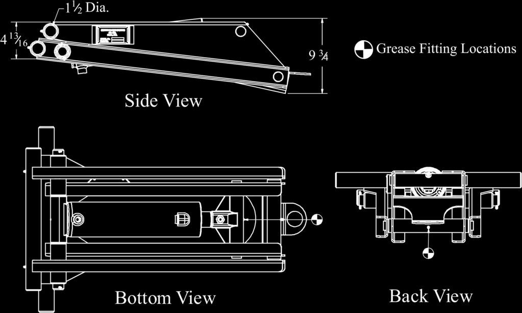
21 CS412TRK Dimensions 21

22 CS412TRK Parts List CS412TRK Parts List (refer to engineering drawing A12454) Item Qty. Part Number Description 1 1 W12439 Scissor Hoist Weldment, CS412T 2 2 W12451 Upper lift Arm Weldment, CS412T A1 Hex Bolt, 1/2 x 2 1/ S Lock Nut, 1/2 5 1 A21324 Cylinder Assembly PC12458 Collar, Lift Arm 1-7/ P34 Set Screw 3/8-16 x 3/4 Square Head 8 1 P10100 Serial Plate 9 4 PAAP43 Rivet, 1/8 Cherry Pop 10 1 SM12580 Bottom Cylinder Shaft, 412T Pin, Cotter 12 2 W12582 Lower Lift Point Weldment 412T 22
23 CS415TRK Capacities CS415TRK Hoist Capacity (Tons) Body Length (Feet) Overhang (Inches) Dump Angle (Degrees) "G" Dimension (Inches) 45 Deg.(76 Inches) 50 Deg. (69 Inches)

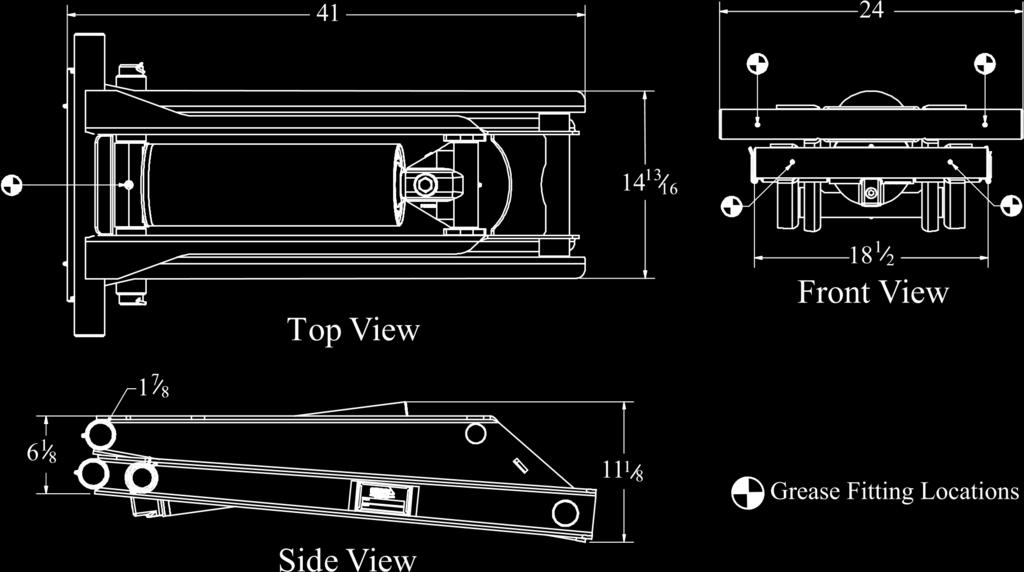
24 CS415TRK Dimensions 24

25 CS415TRK Parts List CS415TRK Parts List (refer to engineering drawing A12337) Item Qty. Part Number Description L Hex Cap Screw, 5/8 x 4, GR PC12161 Collar, Lift Arm 1-7/8 3 8 P34 Set Screw 3/8-16 x 3/4 Square Head Nylon Lock Nut, 5/8 5 2 W12334 Scissor Hoist Weldment, 415T Cotter Pin, 1/4 x 2 1/2 7 1 A21321 Cylinder Assembly 415 DA 8 1 P10200 Serial Plate 9 4 PAAP43 Rivet, 1/8 Cherry Pop 10 2 PC12573 Upper Lift Arm Weldment, 415T 11 2 PC12574 Lower Lift Point Weldment 415T 12 1 SM12016 Bottom Cylinder Shaft, 415T 25
26 CS515TRK Capacities CS515TRK Hoist Capacity (Tons) Body Length (Feet) Overhang (Inches) Dump Angle (Degrees) "G" Dimension (Inches) 45 Deg.(76 Inches) 50 Deg. (69 Inches)

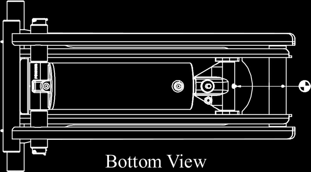
27 CS515TRK Dimensions 27

28 CS515TRK Parts List CS515TRK Parts List (refer to engineering drawing A12338) Item Qty. Part Number Description 1 1 A21322 Cylinder Assembly, 515 DA L Hex Cap Screw, 5/8 x 4, GR PC12161 Collar, Lift Arm 1-7/8 4 8 P34 Set Screw 3/8-16 x 3/4 Square Head Nylon Lock Nut, 5/8 6 1 W12334 Scissor Hoist Weldment, 515T Cotter Pin, 1/4 x 2 1/2 8 2 PC12573 Upper lift Arm Weldment, 515T 9 2 PC12574 Lower Lift Point Weldment 515T 10 4 PAAP43 Rivet, 1/8 Cherry Pop 11 2 PC Spacer 12 1 P10200 Serial Plate 13 1 PC12651 Bottom Cylinder Shaft, 515T 28
29 CS615TRK Capacities CS615TRK Hoist Capacity (Tons) Body Length (Feet) Overhang (Inches) Dump Angle (Degrees) "G" Dimension (Inches) 45 Deg.(76 Inches) 50 Deg. (69 Inches)
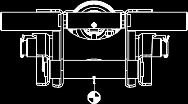
30 CS615TRK Dimensions Back View 30

31 CS615TRK Parts List CS615T Parts List (refer to engineering drawing A12339) Item Qty. Part Number Description L Hex Cap Screw, 5/8 x 4, GR PC12161 Collar, Lift Arm 1-7/8 3 8 P34 Set Screw 3/8-16 x 3/4 Square Head Nylon Lock Nut, 5/8 5 1 W12334 Scissor Hoist Weldment, 615T Cotter Pin, 1/4 x 2 1/2 7 1 A21323 Cylinder Assembly, 615DA 8 4 PAAP43 Rivet, 1/8 Cherry Pop 9 1 P10200 Serial Plate 10 2 PC12573 Upper Lift Arm Weldment, 615T 11 2 PC12574 Lower Lift Point Weldment 615T 12 1 SM12016 Bottom Cylinder Shaft, 615T 31

 Item Qty.")
32 CS412TRK/CS415TRK/CS515TRK/CS615TRK Rear Hinge Assemblies TRK Standard Rear Hinge Parts List (refer to engineering drawing W13678) Item Qty. Part Number Description 1 2 PC10463 Hinge - 1-3/4 Flipper 2 1 F13694 Rear Hinge Angle - Altec 3 2 PC Rear Hinge Support, 1-3/4-50 Degree Bolt-in Pin 4 2 PC /4 Rear Hinge Pin, Short Version A1 Hex Bolt, 3/8 x 3 LG. GR A1 Lock Washer, 3/ A1 Hex Nut, 3/8 UNC 8 2 P800 1/8 Pipe Thread Grease Fitting TRK Optional Rear Hinge Parts List (refer to engineering drawing A131274) Item Qty. Part Number Description 1 1 W Rear Hinge Weldment, 615T Subframe - 50 Degree Dump 2 2 PC10463 Hinge - 1-3/4 Flipper 3 2 PC /4 Rear Hinge Pin, Short Version A1 Hex Bolt, 3/8 x 3 LG. GR A1 Lock Washer, 3/ A1 Hex Nut, 3/8 UNC 7 2 P800 1/8 Pipe Thread Grease Fitting 32
33 CS415LP Capacities CS415LP Hoist Capacity (Tons) Body Length (Feet) Overhang (Inches) Dump Angle (Degrees) "G" Dimension (Inches) 45 Deg.(76 Inches) 50 Deg. (68.5 Inches)

34 CS415LP Dimensions 34
 2 4 PC12161 Collar, Lift Arm 1-7/8 3 8 P34 Set Screw 3/8-16 x 3/4 Square Head 4 2 PC10627 Upper lift Arm, 1-7/8 5 1")
35 CS415LP Parts List CS415LP - Parts List (refer to engineering drawing A12427) Item Qty. Part Number Description 1 1 W12403 Weldment, 415 Scissor Hoist (Fab Cross Tubes) 2 4 PC12161 Collar, Lift Arm 1-7/8 3 8 P34 Set Screw 3/8-16 x 3/4 Square Head 4 2 PC10627 Upper lift Arm, 1-7/ L Hex Cap Screw, 5/8 x 4, GR9 6 1 A DA Cylinder Assembly Pin, Cotter PC13286 Lower Lift Arm, 1-7/8 9 1 P10200 Serial Plate 10 4 PAAP43 Rivet, 1/8 Cherry Pop Lock Nut, 5/8 UNC 12 1 PC12651 Bottom Cylinder Shaft, 415/415T 35
36 CS515LP Capacities CS515LP Hoist Capacity (Tons) Body Length (Feet) Overhang (Inches) Dump Angle (Degrees) "G" Dimension (Inches) 45 Deg.(76 Inches) 50 Deg. (68.5 Inches)

37 CS515LP Dimensions 37
 2 2 PC13286 Lower Lift Arm, 1-7/8 3 8 P34 Set Screw 3/8-16 x 3/4 Square Head 4 4 PC12161 Collar, Lift Arm 1-7/8 5 1")
38 CS515LP Parts List CS515LP - Parts List (refer to engineering drawing A12428) Item Qty. Part Number Description 1 1 W12403 Weldment, 515 Scissor Hoist (Fab Cross Tubes) 2 2 PC13286 Lower Lift Arm, 1-7/8 3 8 P34 Set Screw 3/8-16 x 3/4 Square Head 4 4 PC12161 Collar, Lift Arm 1-7/8 5 1 PC12651 Bottom Cylinder Shaft, 515/515T Pin, Cotter PC Spacer 8 1 A DA Cylinder Assembly Nut, Lock, 5/8 UNC 10 2 PC10627 Upper lift Arm, 1-7/ L Hex Cap Screw, 5/8 x 4, GR PAAP43 Rivet, 1/8 Cherry Pop 13 1 P10100 Serial Plate 38
39 CS615LP Capacities CS615LP Hoist Capacity (Tons) Body Length (Feet) Overhang (Inches) Dump Angle (Degrees) "G" Dimension (Inches) 45 Deg.(76 Inches) 50 Deg. (68.5 Inches)

40 CS615LP Dimensions 40
 2 2 PC13286 Lower Lift Arm, 1-7/8 3 8 P34 Set Screw 3/8-16 x 3/4 Square Head 4 4 PC12161 Collar, Lift Arm 1-7/8 5")
41 CS615LP Parts List GS615LP - Parts List (refer to engineering drawing A12429) Item Qty. Part Number Description 1 1 W12403 Weldment, CS615LP Scissor Hoist (Fab Cross Tubes) 2 2 PC13286 Lower Lift Arm, 1-7/8 3 8 P34 Set Screw 3/8-16 x 3/4 Square Head 4 4 PC12161 Collar, Lift Arm 1-7/8 5 1 PC12651 Bottom Cylinder Shaft Pin, Cotter A21325 Cylinder Assembly, 615DA Lock Nut, Nylon, 5/8 UNC 9 2 PC10627 Upper lift Arm, 1-7/ L Hex Cap Screw, 5/8 x 4, GR PAAP43 Rivet, 1/8 Cherry Pop 12 1 P10100 Serial Plate 41
42 CS615HDLP Capacities CS615HDLP Hoist Capacity (Tons) Body Length (Feet) Overhang (Inches) Dump Angle (Degrees) "G" Dimension (Inches) 45 Deg.(82 Inches) 50 Deg. (74 Inches)

43 CS615HDLP Dimensions 43
 2 1 116-7-A1 Hex Nut, 5/8 UNC 3 2 PC10626 Upper lift Arm, 2-1/4 4 8 P34 Set Screw 3/8-16 x 3/4 Square Head 5 4")
44 CS615HDLP Parts List GS615HDLP - Parts List (refer to engineering drawing A12557) Item Qty. Part Number Description 1 1 W HD Scissor Hoist Weldment (Fab Cross Tubes) A1 Hex Nut, 5/8 UNC 3 2 PC10626 Upper lift Arm, 2-1/4 4 8 P34 Set Screw 3/8-16 x 3/4 Square Head 5 4 PC12157 Set Collar for 2-1/4 Lift Arm L Hex Cap Screw, 5/8 x 4, GR9 7 1 A DA Cylinder Assembly 8 4 PAAP43 Rivet, 1/8 Cherry Pop 9 1 P10200 Serial Plate, Champion 10 2 PC13285 Lower Lift Arm, 2-1/ SM12048 Bottom Cylinder Shaft, A1 Hex Bolt, 3/8 x 3 LG. GR A1 Lock Washer, 3/ A1 Hex Nut, 3/8 UNC 44
45 CS620HDLP Capacities CS620HDLP Hoist Capacity (Tons) Body Length (Feet) Overhang (Inches) Dump Angle (Degrees) "G" Dimension (Inches) 45 Deg.(105.5 Inches) 50 Deg. (95.5 Inches)

46 CS620HDLP Dimensions 46
 CS620HDLP 2 1 116-7-A1 Hex Nut, 5/8 UNC 3 2 PC10626 Upper lift Arm, 2-1/4 4 4 PC12157 Set Collar for Upper Lift Arm 2-1/4 5")
47 CS620HDLP Parts List GS620HDLP - Parts List (refer to engineering drawing A12556) Item Qty. Part Number Description 1 1 W12489 Scissor Hoist Weldment (Fab Cross Tubes) CS620HDLP A1 Hex Nut, 5/8 UNC 3 2 PC10626 Upper lift Arm, 2-1/4 4 4 PC12157 Set Collar for Upper Lift Arm 2-1/4 5 8 P34 Set Screw 3/8-16 x 3/4 Square Head L Hex Cap Screw, 5/8 x 4, GR9 7 1 A DA Cylinder Assembly 8 4 PAAP43 Rivet, 1/8 Cherry Pop 9 1 P10100 Serial Plate 10 2 PC13285 Lower Lift Arm, 2-1/ PC12601 Cylinder Mount Shaft A1 Hex Bolt, 3/8 x 3 LG. GR A1 Lock Washer, 3/ A1 Hex Nut, 3/8 UNC 47
48 CS6615LP Capacities CS6615LP Hoist Capacity (Tons) Body Length (Feet) Overhang (Inches) Dump Angle (Degrees) "G" Dimension (Inches) 45 Deg.(82 Inches) 50 Deg. (74 Inches)

49 CS6615LP Dimensions 49
 2 2 W21214 615 DA Cylinder Assembly 3 4 PAAP43 Rivet, 1/8 Cherry Pop 4 1 P10100 Serial Plate 5 2 PC13285 Lower Lift Arm, 2-1/4 6 8 P34 Set Screw 3/8-16 x 3/4 Square Head 7 4 PC12157 Set")
50 CS6615LP Parts List CS6615LP - Parts List (refer to engineering drawing A12552) Item Qty. Part Number Description 1 1 W Scissor Hoist Weldment (Fab. Lift Arms) 2 2 W DA Cylinder Assembly 3 4 PAAP43 Rivet, 1/8 Cherry Pop 4 1 P10100 Serial Plate 5 2 PC13285 Lower Lift Arm, 2-1/4 6 8 P34 Set Screw 3/8-16 x 3/4 Square Head 7 4 PC12157 Set Collar for 2-1/4 Lift Arm 8 1 SM12058 Bottom Cylinder Shaft, A1 Hex Bolt, 3/8 x 3 LG. GR A1 Lock Washer, 3/ A1 Hex Nut, 3/8 UNC Lock Nut, Nylon, 5/8 UNC 13 2 PC10626 Upper lift Arm, 2-1/ L Hex Cap Screw, 5/8 x 4, GR9 50
51 CS6620LP Capacities CS6620LP Hoist Capacity (Tons) Body Length (Feet) Overhang (Inches) Dump Angle (Degrees) "G" Dimension (Inches) 45 Deg.(106.5 Inches) 50 Deg. (96.5 Inches)

52 CS6620LP Dimensions 52
 2 2 A21387 620 DA Cylinder Assembly & Cap with O-Ring fittings 3 1 P10200 Serial Plate 4 4 PAAP43 Rivet, 1/8 Cherry Pop 5 2 PC13285 Lower Lift Arm, 2-1/4 6 8 P34 Set Screw 3/8-16")
53 CS6620LP Parts List CS6620LP - Parts List (refer to engineering drawing A12649) Item Qty. Part Number Description 1 1 W Scissor Hoist Weldment (Fab. Saddle & Lift Arms) 2 2 A DA Cylinder Assembly & Cap with O-Ring fittings 3 1 P10200 Serial Plate 4 4 PAAP43 Rivet, 1/8 Cherry Pop 5 2 PC13285 Lower Lift Arm, 2-1/4 6 8 P34 Set Screw 3/8-16 x 3/4 Square Head 7 4 PC12157 Set Collar for 2-1/4 Lift Arm 8 1 SM12058 Bottom Cylinder Shaft, A1 Hex Bolt, 3/8 x 3 LG. GR A1 Lock Washer, 3/ A1 Hex Nut, 3/8 UNC A1 Hex Nut, 5/8 UNC 13 2 PC10626 Upper lift Arm, 2-1/ L Hex Cap Screw, 5/8 x 4, GR9 53
54 CS628LP Capacities CS628LP Hoist Capacity (Tons) Body Length (Feet) Overhang (Inches) Dump Angle (Degrees) "G" Dimension (Inches) 45 Deg.(132 Inches) 50 Deg. (119.5 Inches)

55 CS628LP Dimensions 55
 2 1 116-7-A1 Hex Nut, 5/8 UNC 3 2 PC10626 Upper lift Arm, 2-1/4 4 4 PC12157 Set Collar for 2-1/4 Lift Arm 5 8 P34 Set")
56 CS628LP Parts List CS628LP - Parts List (refer to engineering drawing A12554) Item Qty. Part Number Description 1 1 W Scissor Hoist Weldment (Fab Cross Tubes) A1 Hex Nut, 5/8 UNC 3 2 PC10626 Upper lift Arm, 2-1/4 4 4 PC12157 Set Collar for 2-1/4 Lift Arm 5 8 P34 Set Screw 3/8-16 x 3/4 Square Head L Hex Cap Screw, 5/8 x 4, GR9 7 1 A DA Cylinder Assembly 8 1 P10100 Serial Plate 9 4 PAAP43 Rivet, 1/8 Cherry Pop 10 2 PC13285 Lower Lift Arm, 2-1/ SM12048 Bottom Cylinder Shaft, A1 Hex Bolt, 3/8 x 3 LG. GR A1 Lock Washer, ⅜ A1 Hex Nut, 3/8 UNC 56
57 CS5530LP Capacities CS5530LP Hoist Capacity (Tons) Body Length (Feet) Overhang (Inches) Dump Angle (Degrees) "G" Dimension (Inches) 45 Deg.(138 Inches) 50 Deg. (125 Inches)

58 CS5530LP Dimensions 58
 2 2 A21409 530 DA Cylinder Assembly with O-Ring Fittings 3 1 P10200 Serial Plate 4 4 PAAP43 Rivet, 1/8 Cherry Pop 5 2")
59 CS5530LP Dimensions CS5530LP - Parts List (refer to engineering drawing A12553) Item Qty. Part Number Description 1 1 W Scissor Hoist Weldment (Fab Cross Tubes) 2 2 A DA Cylinder Assembly with O-Ring Fittings 3 1 P10200 Serial Plate 4 4 PAAP43 Rivet, 1/8 Cherry Pop 5 2 PC13285 Lower Lift Arm, 2-1/4 6 8 P34 Set Screw 3/8-16 x ¾ Square Head 7 4 PC12157 Set Collar for 2-1/4 Lift Arm 8 1 SM12058 Bottom Cylinder Shaft, A1 Hex Bolt, 3/8 x 3 LG. GR A1 Lock Washer, 3/ A1 Hex Nut, 3/8 UNC A1 Hex Nut, 5/8 UNC 13 2 PC10626 Upper lift Arm, 2-1/ L Hex Cap Screw, 5/8 x 4, GR9 59
60 CS6630LP Capacities CS6630LP Hoist Capacity (Tons) Body Length (Feet) Overhang (Inches) Dump Angle (Degrees) "G" Dimension (Inches) 45 Deg.(138 Inches) 50 Deg. (125 Inches)

61 CS6630LP Dimensions 61
 2 2 A21415 630 DA Cylinder Assembly with O-ring Fittings 3 1 P10200 Serial Plate")

62 CS6630LP Parts List GS6630LP - Parts List (refer to engineering drawing A12547) Item Qty. Part Number Description 1 1 W Scissor Hoist Weldment (Fab Cross Tubes) 2 2 A DA Cylinder Assembly with O-ring Fittings 3 1 P10200 Serial Plate 4 4 PAAP43 Rivet, 1/8 Cherry Pop 5 2 PC13285 Lower Lift Arm, 2-1/4 6 8 P34 Set Screw 3/8-16 x 3/8 Square Head 7 4 PC12157 Set Collar for 2-1/4 Lift Arm 8 1 SM12058 Bottom Cylinder Shaft A1 Hex Bolt, 3/8 x 3 LG. GR A1 Lock Washer, 3/ A1 Hex Nut, 3/8 UNC A1 Hex Nut, 5/8 UNC 13 2 PC10626 Upper lift Arm, 2-1/ L Hex Cap Screw, 5/8 x 4, GR9 62

63 Rear Hinge Assembly (A20062) 63
64 Date Maintenance and Service Record Maintenance and Services Performed 64
CHAMPION. Hoist and EquipmentGodwinTheGrouOperation & Installation poperation Manual 5530DM UNDERBODY HOIST
 CHAMPION GodwinTheGrouOperation & Installation poperation Manual 5530DM UNDERBODY HOIST CHAMPION HOIST & EQUIPMENT 200 Champion Drive Dunn, N.C. 28334 800-649-4995 3/2009 2 UNDERBODY HOIST Table of Contents
PAGE DESCRIPTION REF. NO.
 TABLE OF CONTENTS VC 628 / 5520 / 6620 MANUAL PAGE DESCRIPTION REF. NO. 1 READ THIS FIRST... 416756 2 IMPORTANT WARNING... 416086 3 WARNING AND CAUTION DECAL LOCATIONS... 416128 4 DECAL DRAWINGS & LIST...
TABLE OF CONTENTS VC 620 / 628 / 5520 / 6620 / 6628 MANUAL TABLE OF CONTENTS F VC VC 6628 PAGE DESCRIPTION REF. NO.
 TABLE OF CONTENTS VC 620 / 628 / 5520 / 6620 / 6628 MANUAL PAGE DESCRIPTION REF. NO. 1 READ THIS FIRST... 416733 2 IMPORTANT WARNING... 416086 3 WARNING AND CAUTION DECALS... 416128 4 VC 620 CAPACITIES...
Rugby Manufacturing SR-Series Hoist Manual. Preface INSTALLATION & OPERATION MANUAL
 Preface INSTALLATION & OPERATION MANUAL INTRODUCTION IMPORTANT!! Read this manual thoroughly prior to installation and operation. This manual outlines the installation and operation of an SR-series hoist
PAGE DESCRIPTION REF. NO.
 TABLE OF CONTENTS VC 620 MANUAL PAGE DESCRIPTION REF. NO. 1 READ THIS FIRST... 416733 2 IMPORTANT WARNING... 416086 3 WARNING AND CAUTION DECAL LOCATIONS... 416128 4 DECAL DRAWINGS & LIST... 628820 5 VC
MODEL LR-2066 & LR-2866A HOIST INSTALLATION AND OPERATION MANUAL
 TRUCK BODIES & EQUIPMENT INTERNATIONAL, Inc. Website: www.rugbymfg.com E-mail: sales@rugbymfg.com Phone: 1-800-869-9162 03 5839 MODEL LR-2066 & LR-2866A HOIST INSTALLATION AND OPERATION MANUAL Hoist Serial
PAGE DESCRIPTION REF. NO.
 TABLE OF CONTENTS VC 416 / 516 MANUAL PAGE DESCRIPTION REF. NO. 1 READ THIS FIRST... 416723 2 IMPORTANT WARNING... 416272 3 BODY PROP AND WARNING / CAUTION DECALS... 416288 4 DECAL LOCATIONS... 416128
PAGE DESCRIPTION REF. NO.
 TABLE OF CONTENTS VC 416 / 516 MANUAL PAGE DESCRIPTION REF. NO. 1 READ THIS FIRST... 416723 2 IMPORTANT WARNING... 416272 3 BODY PROP AND WARNING / CAUTION DECALS... 416288 4 DECAL LOCATIONS... 416128
Premium Supply. Direct Push. Models PCK-3530-DP PCK DP PCK-530-DP. Operator s Manual and Installation Instructions
 Direct Push Models PCK-3530-DP PCK-3530-2DP PCK-530-DP Operator s Manual and Installation Instructions Premium Supply 2038 West Interstate 30 866-934-0777 Proud members of: and June 20, 2018 Table of Contents
MODEL TB-8, TB-10, TB-12, & TB-14 TRAILER HOIST INSTALLATION AND OPERATION MANUAL
 TRUCK BODIES & EQUIPMENT INTERNATIONAL, Inc. Website: www.tbei.com E-mail: sales@tbei.com Phone: 1-800-869-9162 1-800-533-0494 090001 MODEL TB-8, TB-10, TB-12, & TB-14 TRAILER HOIST INSTALLATION AND OPERATION
CHAMPION. Hoist and Equipment Dunn, North Carolin, U.S.A. AN AFFILIATE OF 200 CHAMPION DRIVE DUNN, N.C (910) FAX: (910)
 FAX: (910)") CHAMPION Hoist and Equipment Dunn, North Carolin, U.S.A. AN AFFILIATE OF 200 CHAMPION DRIVE DUNN, N.C. 28334 (910) 897-4995 FAX: (910) 897-7306 TRAILER CONVERSION HOIST WARRANTY Champion Hoist and Equipment
CHAMPION Hoist and Equipment Dunn, North Carolin, U.S.A. AN AFFILIATE OF 200 CHAMPION DRIVE DUNN, N.C. 28334 (910) 897-4995 FAX: (910) 897-7306 TRAILER CONVERSION HOIST WARRANTY Champion Hoist and Equipment
LR-416, LR-165, LR-25 INSTALLATION AND OPERATION MANUAL
 RUGBY MANUFACTURING CO. INDUSTRIAL PARK 515 1st STREET NE RUGBY, NORTH DAKOTA 58368 03 5753 LR-416, LR-165, LR-25 INSTALLATION AND OPERATION MANUAL To Be Filled In By Installer Hoist Installed: Hoist Serial
Rugby Manufacturing TB-8/10/12/14 Hoist Manual. Preface INSTALLATION & OPERATION MANUAL
 Preface INSTALLATION & OPERATION MANUAL INTRODUCTION IMPORTANT!! Read this manual thoroughly prior to installation and operation. This manual outlines the installation and operation of a TB-Series hoist
Operating & Maintenance
 TL & C SERIES Operating & Maintenance A B C D E F TO RAISE HOIST 1. Start Engine in neutral 2. Depress the clutch and engage the P.T.O. 3. Release the clutch and open the hydraulic valve. If the pump squeals,
TABLE OF CONTENTS VC 620 W/ LINKAGE BODY PROP MANUAL TABLE OF CONTENTS VC 620 W/ LINK. PROP
 TABLE OF CONTENTS VC 620 W/ LINKAGE BODY PROP MANUAL PAGE DESCRIPTION REF. NO. 1 READ THIS FIRST... 416733 2 IMPORTANT WARNING...416086 3 WARNING AND CAUTION DECAL LOCATIONS... 416850 4 DECAL DRAWINGS
Website: ELIMINATOR MD. (701) (800)
 (800)") Website: www.tbei.com E-mail: sales@tbei.com ELIMINATOR MD www.rugbymfg.com sales@rugbymfg.com (701) 776-5722 (800) 533-0494 1228633 1 DATE PURCHASED BODY SERIAL NUMBER HOIST SERIAL NUMBER CYLINDER SERIAL
Website: www.tbei.com E-mail: sales@tbei.com ELIMINATOR MD www.rugbymfg.com sales@rugbymfg.com (701) 776-5722 (800) 533-0494 1228633 1 DATE PURCHASED BODY SERIAL NUMBER HOIST SERIAL NUMBER CYLINDER SERIAL
MARATHON TELESCOPIC HOIST
 Website: www.tbei.com E-mail: sales@tbei.com CRYSTEEL S MARATHON TELESCOPIC HOIST this manual must be included with the vehicle after completing the installation. Web Site E-Mail Phone (507) 726-2728 www.crysteel.com
OWNERS MANUAL. GMC C K AND 19K GVW CHASSIS CAB 2004-NEWER MODELS (Link Part No. 8M000050) PROUDLY INSTALLED BY : COMPANY : INSTALLER SIGNATURE :
 PROUDLY INSTALLED BY : COMPANY : INSTALLER SIGNATURE :") OWNERS MANUAL GMC C5500 15K AND 19K GVW CHASSIS CAB 2004-NEWER MODELS (Link Part No. 8M000050) Link Mfg. Ltd. 223 15th St. N.E. Sioux Center, IA USA 51250-2120 (712) 722-4868 Fax (712) 722-4779 QUESTIONS?
OWNERS MANUAL GMC C5500 15K AND 19K GVW CHASSIS CAB 2004-NEWER MODELS (Link Part No. 8M000050) Link Mfg. Ltd. 223 15th St. N.E. Sioux Center, IA USA 51250-2120 (712) 722-4868 Fax (712) 722-4779 QUESTIONS?
DUMP BODY SPREADERS INSTALLATION INSTRUCTIONS
 DUMP BODY SPREADERS INSTALLATION INSTRUCTIONS (Includes PS350 & PS400) EFFECTIVE 09/2011 Revision A 1330 76TH AVE SW CEDAR RAPIDS, IA 52404-7052 PHONE (319) 363-8281 FAX (319) 286-3350 www.highwayequipment.com
PAGE DESCRIPTION REF. NO.
 TABLE OF CONTENTS VC 416 / 516 MANUAL PAGE DESCRIPTION REF. NO. 1 READ THIS FIRST... 416733 2 IMPORTANT WARNING... 416272 3 BODY PROP AND WARNING / CAUTION DECALS... 416288 4 DECAL LOCATIONS... 416128
TRAILER INSTALLATION INSTRUCTIONS
 TRAILER INSTALLATION INSTRUCTIONS 8A000450 DuraMax 20,000 LB. CAPACITY Link Mfg. Ltd. 223 15th St. N.E. Sioux Center, IA USA 51250-2120 www.linkmfg.com QUESTIONS? CALL CUSTOMER SERVICE 1-800-222-6283 Refer
RIGID LIFT INSTALLATION & OPERATION MANUAL MODELS: RL-B10 THRU RL-L125
 RIGID LIFT INSTALLATION & OPERATION MANUAL MODELS: RL-B10 THRU RL-L125 THIS MANUAL IS TO BE USED IN CONJUNCTION WITH THE APPROPRIATE PUMP INSTALLATION MANUAL AND HOIST PARTS LIST. IMPORTANT FAILURE TO
TruckCraft Corporation Rev. 1/28/2016 I Table of Contents
 TruckCraft Corporation Rev. 1/28/2016 I5-05579 TRUCKCRAFT CORPORATION 5751 Molly Pitcher Hwy. S. Chambersburg, Pa. 17202 Tel. 800.375.3867 Phone 717.375.2900 Fax 717.375.2975 www.truckcraft.com "WHERE
HR-520 HOIST. Installation & Operation Manual. To Be Filled In By Installer. Pump Installation And Operation Manual#: In Service Date: Dealer:
 Website: www.tbei.com E-mail: sales@tbei.com Phone: 1-800-869-9162 Rugby 1-800-255-4345 DuraClass 1-800-533-0494 Crysteel HR-520 HOIST Installation & Operation Manual To Be Filled In By Installer Hoist
1500 Series Roll Off Hoist. Owner s Manual (5-06)
") 1500 Series Roll Off Hoist Owner s Manual (5-06) Section 1: General Information Introduction Safety Information Warranty Information Table of Contents Section 2: Operation Operating the P.T.O. Operating
1500 Series Roll Off Hoist Owner s Manual (5-06) Section 1: General Information Introduction Safety Information Warranty Information Table of Contents Section 2: Operation Operating the P.T.O. Operating
CDL Series Pre-Trip Inspection AT-TC3TS T1-JA01. Pre-Trip Inspection Checklist
 Pre-Trip Inspection Checklist This checklist covers different parts of the vehicle you would check before a trip. Note that some specifications described in the following content may not be the same as
HR-540/HR-550 HOIST Installation & Operation Manual
 Website: www.tbei.com E-mail: sales@tbei.com Phone: 1-800-869-9162 Rugby 1-800-255-4345 DuraClass 1-800-533-0494 Crysteel HR-540/HR-550 HOIST Installation & Operation Manual To Be Filled In By Installer
LR-3510 Install and Operation Manual
 RUGBY MANUFACTURING CO. INDUSTRIAL PARK 515 1st St. NE. RUGBY, NORTH DAKOTA 58368 03 6048 Install and Operation Manual LATEST EDITION: 1st (January 4, 2001) FIRST EDITION: January 4, 2001 Page 2 of 9 WARNINGS:
KING COBRA/CALIBER GRASS COLLECTION SYSTEM PARTS & OPERATORS MANUAL
 KING COBRA/CALIBER GRASS COLLECTION SYSTEM PARTS & OPERATORS MANUAL GRASS CATCHER W/WEIGHTS: TUBE KITS: BLOWER KITS: 52 542128 52 542119 5101002 60 542129 60 542120 5101003 2 WORLDLAWN POWER EQUIPMENT
<THESE INSTRUCTIONS MUST BE GIVEN TO THE END USER> B&W
 B&W Trailer Hitches 6 Hawaii Rd / PO Box 86 Humboldt, KS 66748 P:60.473664 F:60.869.903 Turnoverball Gooseneck Hitch Installation Instructions MODEL 08
WARNING!! C-659 SUBKIT FIGURE 4
 '0-'0 DODGE / TON TRUCKS '03-' DODGE 3/ & TON TRUCKS (WILL FIT /, 3/ & TON MEGA CAB SHORT BED) WARNING!! BRAKE, FUEL, AND ELECTRICAL LINES MAY NEED TO BE LOOSENED OR REPOSITIONED TO PROVIDE CLEARANCE FOR
LR-26B, LR-27B, LR-28A, or LR-623 INSTALLATION AND OWNER'S MANUAL
 INDUSTRIAL PARK 515 1ST STREET NORTH EAST RUGBY, ND 58368 03 5804 LR-26B, LR-27B, LR-28A, or LR-623 INSTALLATION AND OWNER'S MANUAL Hoist Installed: Hoist Serial #: To Be Filled In By Installer Pump Installation
INSTALLATION INSTRUCTIONS
 TM WEIGHTLIFTER Tailgates By THIEMAN TWL 125, 16, 20 INSTALLATION INSTRUCTIONS! IMPORTANT! KEEP IN VEHICLE! PLEASE READ AND UNDERSTAND THE CONTENTS OF THIS MANUAL BEFORE OPERATING THE EQUIPMENT. NTEA T
Rugby Manufacturing Direct Mount Unit Manual
 Preface INSTALLATION & OPERATION MANUAL INTRODUCTION IMPORTANT!! Read this manual thoroughly prior to installation and operation. This manual outlines the installation and operation of a Direct Mount unit
Required tools General hand tools 21/64" drill bit Torque wrench Threadlocker Center punch
 Slipper Spring Kit (part numbers 2560, 2570 and 2580) Item Qty Part number Description 1... 8... 350054-50...3/8-16 x 1" grade 8 self-tapping screw 2... 4... 350084-00...7/16-14 x 4" grade 5 3... 6...
MID RISE. INSTALLATION and OPERATION MANUAL MODEL 6000A // 6000E 6,000 LB. CAPACITY. READ and SAVE THIS INSTRUCTION MANUAL
 INSTALLATION and OPERATION MANUAL MID RISE MODEL 6000A // 6000E 6,000 LB. CAPACITY READ and SAVE THIS INSTRUCTION MANUAL AUGUST 2005 6-0944 6500 Millcreek Drive Mississauga, Ontario Canada L5N 2W6 1-800-268-7959
OWNERS MANUAL GM C4500/C5500 DANA MODEL S135 REAR AXLE 2003-NEWER MODELS LINK MFG. PART NO. 8M PROUDLY INSTALLED BY : COMPANY :
 OWNERS MANUAL GM C4500/C5500 DANA MODEL S135 REAR AXLE 2003-NEWER MODELS LINK MFG. PART NO. 8M000030 Link Mfg. Ltd. 223 15th St. N.E. Sioux Center, IA USA 51250-2120 (712) 722-4874 Fax (712) 722-4876 QUESTIONS?
Installation Manual. LHS & LLBS Hide-A-Way Tuckunder Style
 Installation Manual LHS & LLBS Hide-A-Way Tuckunder Style 10900 Kenwood Road Cincinnati, OH 45242 Ph: 513-891-6210 Toll-Free: 866-539-6261 Fax: 513-891-4901 www.leymanlift.com sales@leymanlift.com LML00136-5/1/15
OWNERS MANUAL/PARTS LIST
 STOWAWAY Tailgates By THIEMAN Model ST-40 OWNERS MANUAL/PARTS LIST! IMPORTANT! KEEP IN VEHICLE! PLEASE READ AND UNDERSTAND THE CONTENTS OF THIS MANUAL BEFORE OPERATING THE EQUIPMENT. NATIONAL TRUCK EQUIPMENT
WARNING indicates a potentially hazardous situation which, if not avoided, could result in property damage, serious personal injury or even death.
 Comfort Ride Third axle slipper leaf spring system (part numbers 2560-50, 2570-50 and 2580-50) and shock absorber system (part numbers 2450-50, 2460-50 and 2470-50) Installation Instructions All specifications
INSTALLATION OF RAILGEAR KIT R-290HD REAR
 INSTALLATION OF RAILGEAR KIT R-290HD REAR Page 1 of 29 SAFETY PRECAUTIONS If any installation problems are encountered, please call G&B Specialties, Inc. for technical assistance before continuing with
INSTALLATION INSTRUCTIONS
 INSTALLATION INSTRUCTIONS GMT 560 (4500/5500) CREW CAB (2351A000) Link Mfg. Ltd. 223 15th St. N.E. Sioux Center, IA USA 51250-2120 The CABMATE MODEL 2351A000 fits the 2003 and later GM 4500 / 5500 crew
GRASS CATCHER PART S & OPERATORS MANUAL
 GRASS CATCHER PART S & OPERATORS MANUAL WORLDLAWN POWER EQUIPMENT, INC. WORLDLAWN.COM 2415 ASHLAND AVE BEATRICE, NE 68310 800-267-4255 FAX 402-223-4103 2 3 4 OPERATORS MANUAL This catcher manual is for
CRYSTEEL S HOIST. this manual must be included with the vehicle after completing the installation.
 Website: www.tbei.com E-mail: sales@tbei.com CRYSTEEL S STINGRAY HOIST this manual must be included with the vehicle after completing the installation. Web Site E-Mail Phone (507) 726-2728 www.crysteel.com
Comfort Ride Shock absorber system part numbers 2450, 2460 and 2470 Installation Instructions
 Comfort Ride Shock absorber system part numbers 2450, 2460 and 2470 Installation Instructions All specifications are subject to change without notice. Item Qty Part number Description 1... 4... 204000-00...shock
Railgates By THIEMAN VL-30, 40, 50 OWNERS MANUAL/PARTS LIST IMPORTANT! KEEP IN VEHICLE!
 VL SERIES Railgates By THIEMAN VL-30, 40, 50 OWNERS MANUAL/PARTS LIST! IMPORTANT! KEEP IN VEHICLE! PLEASE READ AND UNDERSTAND THE CONTENTS OF THIS MANUAL BEFORE OPERATING THE EQUIPMENT. NATIONAL TRUCK
INSTALLATION INSTRUCTIONS
 INSTALLATION INSTRUCTIONS 8A000729 DuraLift 13.5 13,500 LB. CAPACITY Link Mfg. Ltd. 223 15th St. N.E. Sioux Center, IA USA 51250-2120 www.linkmfg.com QUESTIONS? CALL CUSTOMER SERVICE 1-800-222-6283 Refer
INSTRUCTION MANUAL 16K - Fifth Wheel Hitch
 You can take it with you. INSTRUCTION MANUAL 16K - Fifth Wheel Hitch Product No. 30047 DEALER/INSTALLER: END USER: (1) Provide this Manual to end user. (2) Physically demonstrate hitching and unhitching
Easy Approach OEM INSTALLATION MANUAL (FOREST RIVER)
") Easy pproach OEM INSTLLTION MNUL (FOREST RIVER) Introduction TBLE OF CONTENTS Introduction 2 Safety 3 Resources Required 3 Installation 4 Fully ssembled xle Sub-Frame 4 Installing the Hydraulic System
Easy pproach OEM INSTLLTION MNUL (FOREST RIVER) Introduction TBLE OF CONTENTS Introduction 2 Safety 3 Resources Required 3 Installation 4 Fully ssembled xle Sub-Frame 4 Installing the Hydraulic System
Turning Point Pin Box. by Trailair OWNER'S MANUAL
 Turning Point Pin Box by Trailair OWNER'S MANUAL TABLE OF CONTENTS Product and Safety Information 2 Preparation 3 Tow Rating Weights Check 3 Cab and Bed Clearance Check 3 Operation 3 Conventional Transport
M16, 20, 25, 30 MLB16, 20, 25, 30 OWNERS MANUAL/PARTS LIST
 STOWAWAY Tailgates By THIEMAN M16, 20, 25, 30 MLB16, 20, 25, 30 OWNERS MANUAL/PARTS LIST! IMPORTANT! KEEP IN VEHICLE! PLEASE READ AND UNDERSTAND THE CONTENTS OF THIS MANUAL BEFORE OPERATING THE EQUIPMENT.
OWNERS MANUAL GM C4500/C5500 4X4 DANA MODEL S135 REAR AXLE 2005-NEWER MODELS LINK MFG. PART NO. 8M PROUDLY INSTALLED BY : COMPANY :
 OWNERS MANUAL GM C4500/C5500 4X4 DANA MODEL S135 REAR AXLE 2005-NEWER MODELS LINK MFG. PART NO. 8M000060 Link Mfg. Ltd. 223 15th St. N.E. Sioux Center, IA USA 51250-2120 (712) 722-4874 Fax (712) 722-4876
Package Contents Part A (3) I-Beam (1) Base (2) Other parts
 I-Beam (1) Base (2) Other parts") Page 1 Installation Instructions for 81245 Adjustable Height Gantry Crane 1-Ton Capacity Table of Contents Important Safety Information pg. 2 Specific Operation Warnings pg. 2 Main Parts of Product pg.
Page 1 Installation Instructions for 81245 Adjustable Height Gantry Crane 1-Ton Capacity Table of Contents Important Safety Information pg. 2 Specific Operation Warnings pg. 2 Main Parts of Product pg.
650 Series Cargo Van Lift Mounting Instructions Ford Transit (Standard Roof) 2015-Present
 2015-Present") TOMMY GATE OWNER'S / OPERATOR'S MANUAL 650 Series 650 LB Capacity 650 Series Cargo Van Lift Mounting Instructions Ford Transit (Standard Roof) 2015-Present Installing the Base Plate 1. Examine the interior
TOMMY GATE OWNER'S / OPERATOR'S MANUAL 650 Series 650 LB Capacity 650 Series Cargo Van Lift Mounting Instructions Ford Transit (Standard Roof) 2015-Present Installing the Base Plate 1. Examine the interior
1002 Wayne Avenue Chambersburg, PA Fax: DI-100 OWNER S MANUAL. General Information Instructions Maintenance
 1002 Wayne Avenue Chambersburg, PA 17201 717.261.0922 Fax: 717.264.5581 DI-100 OWNER S MANUAL General Information Instructions Maintenance TABLE OF CONTENTS Installation Instructions... 4-5 Installation
DIAMONDBACK/EDGE GRASS COLLECTION SYSTEM PARTS & OPERATORS MANUAL
 DIAMONDBACK/EDGE GRASS COLLECTION SYSTEM PARTS & OPERATORS MANUAL GRASS CATCHER W/WEIGHT: TUBE KIT: BLOWER KIT: 48 5101305 632093 632078 52 5101305 542119 632074 60 632086 542120 632081 3 WORLDLAWN POWER
2 TON CAPACITY PROFESSIONAL SERIES ALUMINUM JACK OWNER'S MANUAL SPECIFICATIONS
 80006 OWNER'S MANUAL CONTENTS: Page 1 Specifications 2 Warning Information 3 Setup, Operating and Preventative Maintenance 4 Troubleshooting 5 Maintenance 6 Exploded View Drawing and Replacement Parts
INSTALLATION MANUAL ENG-0001-INS-SNG PN:
 INSTALLATION MANUAL ENG-0001-INS-SNG PN:3300000 Revision 12/07/2017 INTENTIONALLY BLANK INSTALLATION MANUAL ENG-0001-INS-SNG PN:3300000 Revision 12/07/2017 Refer to this manual during the upfit & installation
TT-15 INSTALLATION INSTRUCTIONS SHOWN WITH OPTIONAL 2 PC. ALUMINUM PLATFORM AND LIGHT KIT
 TM TOPLIFTER Tailgates By THIEMAN TT-15 INSTALLATION INSTRUCTIONS SHOWN WITH OPTIONAL 2 PC. ALUMINUM PLATFORM AND LIGHT KIT! IMPORTANT! KEEP IN VEHICLE! PLEASE READ AND UNDERSTAND THE CONTENTS OF THIS
<THESE INSTRUCTIONS MUST BE GIVEN TO THE END USER> B&W
 B&W Trailer Hitches 1216 Hawaii Rd / PO Box 186 Humboldt, KS 66748 Turnoverball Gooseneck Hitch Installation Instructions MODEL 1314 2013 2014 RAM 3500
SL15/20-6 AND SL15/20-10 INSTALLATION INSTRUCTIONS
 STOWAWAY SideLoader Tailgates By THIEMAN SL15/20-6 AND SL15/20-10 INSTALLATION INSTRUCTIONS! IMPORTANT! KEEP IN VEHICLE! READ AND UNDERSTAND THE CONTENTS OF THIS MANUAL BEFORE OPERATING THE EQUIPMENT.
Installation Instructions PowerBoard Automatic Retracting Running Board
 Installation Instructions PowerBoard Automatic Retracting Running Board Vehicle Application Dodge Ram 1500 Crew Cab 2009 - Current : 75138-15 Dodge Ram 2500/3500 & HD Crew Cab 2010 - Current : 75138-15
W & A 12 ROW TOP LEVELING STACKER LEVEL BANDER
 W & A 12 ROW TOP LEVELING STACKER LEVEL BANDER NO. 3640 OPERATOR S MANUAL TO THE OWNER: Congratulations on your purchase of a new W & A Top Leveling Stacker Level Bander. Your selection is an indication
RideStar RHP Series Sliding Tandem Trailer Air Suspension System
 Maintenance Manual 14S RideStar RHP Series Sliding Tandem Trailer Air Suspension System Revised 05-14 Service Notes About This Manual This manual provides the correct lubrication, service and installation
TABLE OF CONTENTS SECTION I - INTRODUCTION 1. Introduction... 1 Hoist Description... 1 SECTION II - OPERATING PROCEDURES 3
 TABLE OF CONTENTS Page SAFETY NOTICE WARRANTY SECTION I - INTRODUCTION 1 Introduction............................ 1 Hoist Description........................ 1 SECTION II - OPERATING PROCEDURES 3 Safety
Installation Instructions READ THOROUGHLY BEFORE BEGINNING Signature Series Rail Kit Dodge Ram Trucks-all, including Mega-cabs
 INDEX Failure to follow all of these instructions may result in death or serious injury!. GUIDELINES FOR MATCHING TOW VEHICLE AND TRAILER. Pages -. DRILLED AND BOLTED INSTALLATION FIGURE. Page 4. NO-DRILL,
OWNERS MANUAL. Model No LB. TOW SPIKER SPREADER. CAUTION: Read Rules for Safe Operation and Instructions Carefully
 OWNERS MANUAL Model No. 45-03012 175 LB. TOW SPIKER SPREADER CAUTION: Read Rules for Safe Operation and Instructions Carefully Safety Assembly Operation Maintenance Parts the fastest way to purchase parts
ILM16 ILM20 ILM30 ILM12AF ILM16AF ILM20AF ILM30AF
 ILM Series Liftgates Read Before Installing INSTALLATION MANUAL For Models: ILM12 ILM16 ILM20 ILM30 ILM12AF ILM16AF ILM20AF ILM30AF Interlift, Inc. a Subsidary of MBB Liftsystems AG 15939 Pluma Avenue
Installation Instructions. Attention Dealers: Please give this owners manual to the customer when the product is delivered.
 Serving the Truck & Trailer Industry Since 1944 Attention Dealers: Please give this owners manual to the customer when the product is delivered. Call 800-535-9545 www.aeroindustries.com Indianapolis, IN
Premium Supply. Tilt Deck. Models PCK-TD PCK-PTD CTD-310-K. Operator s Manual and Installation Instructions
 Tilt Deck Models PCK-TD PCK-PTD CTD-310-K Operator s Manual and Installation Instructions Premium Supply 2038 West Interstate 30 866-934-0777 Proud members of: and April 20, 2018 Table of Contents Introduction...
Owner s Manual. LTS Hide-A-Way Truck Side Gate
 Owner s Manual LTS Hide-A-Way Truck Side Gate 10900 Kenwood Road Cincinnati, OH 45242 Ph: 513-891-6210 Toll-Free: 866-539-6261 Fax: 513-891-4901 www.leymanlift.com sales@leymanlift.com LML00410-11/6/15
Rotary Brush Cutter. Model Number RBV. Serial Number. Serial Number and Greater. Maximum Flow Rate gpm. Phone: RBV
 Rotary Brush Cutter Model Number RBV. Serial Number. Serial Number 75 and Greater Maximum Flow Rate gpm. Phone: 0--700 0/5/0 Revised // RBV Features of Virnig Mfg. Inc. Rotary Brush Cutter include: diameter
Model ET 5000W Operation and Service Manual
 Model ET 5000W Operation and Service Manual Patented 5/16 BALL Load Capacity: 5000 lbs The ET 5000W ESCALATE TRAILER offers ground level roll-on loading and roll-off unloading of equipment with non-tilting
Owner s Manual TC-515 with Reversed Hoist, Sub-Frame, Deck, & Hitch Mount
 Proudly built in the USA Owner s Manual TC-55 with Reversed Hoist, Sub-Frame, Deck, & Hitch Mount TruckCraft Corporation Chambersburg, PA -800-755-87 Copyright c 0 www.truckcraft.com TruckCraft Corporation
<THESE INSTRUCTIONS MUST BE GIVEN TO THE END USER> B&W Trailer Hitches 1216 Hawaii Rd / PO Box 186 Humboldt, KS P: F:
 B&W Trailer Hitches 6 Hawaii Rd / PO Box 86 Humboldt, KS 6678 P:60.7366 F:60.73766 Turnoverball Gooseneck Hitch Installation Instructions MODEL 38 0 06
16K Reese Revolution. Operating Instructions
 Operating Instructions DEALER: (1) Provide this Manual to end user END USER: (1) Read and follow this Manual every time you use Sidewinder. (2) Save this Manual for Future Reference. PIN BOX SHOWN ASSEMBLED
BUCKET SWEEPER OPERATORS & PARTS MANUAL 2852 & 3174 SERIES
 OM628 BUCKET SWEEPER OPERATORS & PARTS MANUAL 2852 & 3174 SERIES MODEL 12002-5 FOOT WIDE X 24 INCH DIAMETER (SKID-STEER) MODEL 12004-6 FOOT WIDE X 24 INCH DIAMETER (SKID-STEER) MODEL 12017-6 FOOT WIDE
THE GLIDER 5th Wheel Attachment
 April 2007 APPLICATION: INSTALLATION INSTRUCTIONS MODEL NO. 70460 70046 THE GLIDER 5th Wheel Attachment For use on short bed pickup applications US Patent No. 6247720 COMPLETE PARTS LIST Part Description
High Lift Transmission Jack
 655 Eisenhower Drive Owatonna, MN 55060 USA Phone: (507) 455-7000 Tech. Serv.: (800) 533-6127 Fax: (800) 955-8329 Order Entry: (800) 533-6127 Fax: (800) 283-8665 International Sales: (507) 455-7223 Fax:
INSTRUCTIONS, (FORD) SUPER DUTY INSTALLATION KIT (C2 PICKUP LIFTGATES)
 SUPER DUTY INSTALLATION KIT (C2 PICKUP LIFTGATES)") LIFT CORPORATION Sht. 1 of 20 DSG# M-14-32 Rev. B Date: 05/31/2017 INSTRUCTIONS, (FORD) SUPER DUTY INSTALLATION KIT (C2 PICKUP LIFTGATES) FORD SUPER DUTY F-250 PICKUP TRUCKS, 1999-2016 FORD SUPER DUTY
LIFT CORPORATION Sht. 1 of 20 DSG# M-14-32 Rev. B Date: 05/31/2017 INSTRUCTIONS, (FORD) SUPER DUTY INSTALLATION KIT (C2 PICKUP LIFTGATES) FORD SUPER DUTY F-250 PICKUP TRUCKS, 1999-2016 FORD SUPER DUTY
INSTALLATION MANUAL RA-35 & RA-45 M REV. D SEPTEMBER 2017
 M-13-01 REV. D SEPTEMBER 2017 INSTALLATION MANUAL RA-35 & RA-45 To fi nd maintenance and parts information for your RA Liftgate, go to www.maxonlift.com. Click the PRODUCTS, SLIDELIFT & RA buttons. Open
Table of Contents General Information Safety Message Classifi cation...2 Safety Notes...3 Terminology...4 Coupler Lifting Lug...
 Table of Contents General Information Safety Message Classifi cation...2 Safety Notes...3 Terminology...4 Coupler Lifting Lug...6 Assembly and Installation General Information...7 How it works...7 Component
ASSEMBLY INSTRUCTIONS
 CONTENTS ASSEMBLY INSTRUCTIONS... 1 TO THE DEALER... 1 SAFETY... 1 UNPACKING AND CHECKING PARTS... 2 Unpacking Wooden Crate...2 Checking Parts...3 TRACTOR PREPARATION... 4 ASSEMBLY... 4 Boom Assembly...4
ASSEMBLY INSTRUCTIONS
 CONTENTS ASSEMBLY INSTRUCTIONS... 1 TO THE DEALER... 1 SAFETY... 1 UNPACKING AND CHECKING PARTS... 2 Unpacking Wooden Crate...2 Checking Parts...3 TRACTOR PREPARATION... 4 Tool Box (CAB MODEL)...4 ASSEMBLY...
650 Series Cargo Van Lift Mounting Instructions Fullsize Ford 1992-Present
 TOMMY GATE OWNER'S / OPERATOR'S MANUAL 650 Series 650 LB Capacity 650 Series Cargo Van Lift Mounting Instructions Fullsize Ford 1992-Present Installing the Base Plate 1. Examine the interior and exterior
INSTRUCTIONS AND PARTS LIST FOR MODEL FORCE 10DA and FORCE 25DA (Double Acting, Electrically-Operated Hydraulic Press)
") INSTRUCTIONS AND PARTS LIST FOR MODEL FORCE 10DA and FORCE 25DA (Double Acting, Electrically-Operated Hydraulic Press) Operation 1. Plug power cord into a 115-volt A.C. single phase 60-cycle grounded,
INSTRUCTIONS AND PARTS LIST FOR MODEL FORCE 10DA and FORCE 25DA (Double Acting, Electrically-Operated Hydraulic Press) Operation 1. Plug power cord into a 115-volt A.C. single phase 60-cycle grounded,
INSTALLATION & OWNER S MANUAL
 Rev. C, p. of 2 INSTALLATION & OWNER S MANUAL KUBOTA B2650/3350 Hard Sided Cab p/n KB33AS Soft Sided Cab p/n KB33SS Installation Instructions The contents of this envelope are the property of the owner.
Tailgates By THIEMAN M16, 20, 25, 30 MLB16, 20, 25, 30 INSTALLATION INSTRUCTIONS
 STOWAWAY Tailgates By THIEMAN M16, 20, 25, 30 MLB16, 20, 25, 30 INSTALLATION INSTRUCTIONS M-25 shown! IMPORTANT! KEEP IN VEHICLE! PLEASE READ AND UNDERSTAND THE CONTENTS OF THIS MANUAL BEFORE OPERATING
ProLine. 44 Mower. for 120 Traction Unit. Model No & Up. Operator s Manual
 FORM NO. 9 ProLine Mower for 0 Traction Unit Model No. 05 99000 & Up Operator s Manual IMPORTANT: Read this manual carefully. It contains information about your safety and the safety of others. Also become
MIDRISE MODEL SM60F_1 // SM60F_A 6,500 LB. CAPACITY
 INSTALLATION and OPERATION MANUAL READ THIS INSTRUCTION MANUAL THOROUGHLY BEFORE INSTALLING, OPERATING, SERVICING OR MAINTAINING THE LIFT. SAVE THIS MANUAL. NOV 2007 REV.B MIDRISE MODEL SM60F_1 // SM60F_A
Comfort Ride Shock absorber system part numbers 2450, 2460 and 2470 Installation Instructions
 Comfort Ride Shock absorber system part numbers 2450, 2460 and 2470 Installation Instructions All specifications are subject to change without notice. MOUNTING FLANGE CENTER HOLE FRONT OF Item Qty Part
! CAUTION! ! WARNING!
 Assembly Instructions! 24- and 30-Foot, No-Till Flat Fold Marker Option Used with: 2N-2410 and 2N-3010 Drills 2N-2420 and 2N-3020 Drills When you see this symbol, the subsequent instructions and warnings
Property of American Airlines
 Section 2: Operation 1. GENERAL INFORMATION Safety First! is the motto at Tesco; therefore, the first part of the Operation section begins with safety features and procedures. Operation of the Tesco CL80-20
BUILD YOUR OWN TRUCK HOIST ASSEMBLY AND MOUNTING INSTRUCTIONS FOR TRUCK HOIST (SINGLE LEVER) ITEM #
 ITEM #") 1 of 9 481 Panet Road Winnipeg, MB R2C 2Z1 BUILD YOUR OWN TRUCK HOIST ASSEMBLY AND MOUNTING INSTRUCTIONS FOR TRUCK HOIST (SINGLE LEVER) ITEM #1561075 TRUCK HOIST 7 TON (SINGLE LEVER) ITEM # 1200188 1.
1 of 9 481 Panet Road Winnipeg, MB R2C 2Z1 BUILD YOUR OWN TRUCK HOIST ASSEMBLY AND MOUNTING INSTRUCTIONS FOR TRUCK HOIST (SINGLE LEVER) ITEM #1561075 TRUCK HOIST 7 TON (SINGLE LEVER) ITEM # 1200188 1.
Contents (Page 1 of 3)
") EVO8 Drivers Manual Contents (Page 1 of 3) 5 & 6. General Safety 7. Cars by numbers 8. General Vehicle Layout 9. Deck Maximum Load 10. General Data 11. Tyres Pressures 12. Jacking points for trailer Trailer
EVO8 Drivers Manual Contents (Page 1 of 3) 5 & 6. General Safety 7. Cars by numbers 8. General Vehicle Layout 9. Deck Maximum Load 10. General Data 11. Tyres Pressures 12. Jacking points for trailer Trailer
SECTION SIX MAINTENANCE AND SERVICE INSTRUCTIONS
 SECTION SIX MAINTENANCE AND SERVICE INSTRUCTIONS HYDRAULIC STABILIZERS INTRODUCTION INSTALLATION Stabilizer Frame Mounting 6-1 Installing Stabilizer Legs and Cylinders 6-2 Mounting the Control Valve 6-3
Before equipment use, please read this operation manual carefully. Serial Number: Date Purchased:
 Pushed & Geared Trolleys OPERATION MANUAL This operation manual is intended as an instruction manual for trained personnel who are in charge of installation, maintenance, repair etc. Before equipment use,
Premium Supply. Tilt Deck. Models PCK-TD PCK-PTD. Operator s Manual and Installation Instructions
 Tilt Deck Models PCK-TD PCK-PTD Operator s Manual and Installation Instructions Premium Supply 2038 West Interstate 30 866-934-0777 Proud members of: and June 1, 2015 Table of Contents Introduction...
INSTALLATION, MAINTENANCE, & SAFETY INSTRUCTIONS
 Tarpaulin Systems Flip -N- Go / Quick Mount Flip -N- Go System INSTALLATION, MAINTENANCE, & SAFETY INSTRUCTIONS (800) CRAMARO (800) 272-6276 Plants In: Delaware, Florida, Massachusetts, Nevada, Ohio Install
Rotary Brush Cutter (Standard Flow)
") Rotary Brush Cutter (Standard Flow) Model Number RBV. Serial Number. Serial Number 6795-0050 Maximum Flow Rate gpm. For and 5 GPM Max Models Phone: 0-9-700 0/5/0 Revised // RBV Features of Virnig Mfg.
Rotary Brush Cutter (Standard Flow) Model Number RBV. Serial Number. Serial Number 6795-0050 Maximum Flow Rate gpm. For and 5 GPM Max Models Phone: 0-9-700 0/5/0 Revised // RBV Features of Virnig Mfg.