Preservation. A.1. Preservation for a Period of up to 30 Days. Pág. 2. Memoria ** ON A/C , , TASK
|
|
|
- Dorothy Townsend
- 5 years ago
- Views:
Transcription
1 Annex
2 Pág. 2 Memoria A Preservation A.1. Preservation for a Period of up to 30 Days ** ON A/C , , TASK Preservation for a Period of up to 30 Days 1. Reason for the Job Self Explanatory 2. Job Set-up Information A. Fixtures, Tools, Test and Support Equipment REFERENCE QTY DESIGNATION 856A COVER-FITTED BARE QEC'D ENGINE SHIPPING B. Consumable Materials 3. Job Set-up Subtask A. Not Applicable 4. Procedure Subtask A. Period of up to 30 days - Operable engine (1) On-wing installed engines.
3 (a) Start the engines (Ref. AMM TASK ) and let them become stable at ground idle for 15 to 20 minutes, followed by a thrust reverser cycle (Ref. AMM TASK ). Stop the engines (Ref. AMM TASK ). NOTE: You can ignore this step if you did it during the last engine operation (flight cycle). Under these conditions, consider the engine is preserved for 30 days from time of last operation. (b) Cover entrance to fan inlet cowl and exit openings. CAUTION: OPERATION SHOULD BE CARRIED OUT IN A CONFINED SPACE WITH SUFFICIENT VENTILATION AND ON A FLAT HORIZONTAL SURFACE.
4 Pág. 4 Memoria A.2. Preservation for a Period of up to 90 Days ** ON A/C , , TASK Preservation for a Period of up to 90 Days. 1. Reason for the Job You must do the preservation procedure at the end of engine operation or not earlier than one day before an engine return to shop when the engine must not operate for a period of up to 90 days. This procedure is only applicable to on-wing installed engines. 2. Job Set-up Information A. Consumable Materials REFERENCE DESIGNATION CP2442 * engine oil (Ref ) CP5067 * Lubrication System Corrosion Preventive Oil (Ref ) CP5075 * Corrosion Preventive Additive (Ref ) B. Referenced Information REFERENCE DESIGNATION Check Oil Level and Replenish Engine Automatic Start Engine Shutdown Operational Test of the Thrust Reverser System
5 REFERENCE DESIGNATION 3. Job Set-up Subtask A. Not Applicable 4. Procedure Subtask CAUTION: IF ENGINE WAS FERRIED OR SUBJECTED TO AN IN FLIGHT SHUTDOWN (IFSD), ENGINE MUST BE "DRIED OUT" AND RELUBRICATED WITHIN 24 HOURS PER DRY OUT PROCEDURE OF THIS SECTION. A. Period of up to 90 days Subtask B. Operable Engine Preservation - Period of up to 90 days (1) Do the servicing of the oil tank with an approved mixture of Material No CP2442 (engine oil (Material No. CP2442)) and at least 5 percent of Material No CP5067 (Lubrication System Corrosion Preventive Oil (Material No. CP5067)) or, as an alternative, 7 percent Material No CP5075 (Corrosion Preventive Additive (Material No. CP5075)) by volume (Ref. AMM TASK ). NOTE: In both cases, a minimum of 19 l (5 USgal) of oil mixture is required for preservation motoring. (2) Start the engine (Ref. AMM TASK ) and let it become stable at ground idle for minutes, followed by a thrust reverser cycle (Ref. AMM TASK ) and shutdown (Ref. AMM TASK ). (3) Cover the entrance to fan inlet cowl and exit openings of exhaust nozzle. NOTE: For a period of up to 90 days, the preservation of the fuel system is not necessary. Subtask C. Alternative Procedure. Operable Engine Preservation one day before the Preservation Plan -
6 Pág. 6 Memoria Period of Up to 90 days. (1) Do the servicing of the oil tank with an approved mixture of Material No CP2442 (engine oil (Material No. CP2442)) and at least 5 percent of Material No CP5067 (Lubrication System Corrosion Preventive Oil (Material No. CP5067)) by volume (Ref. AMM TASK ). NOTE: In this case, a minimum of 19l (5 US gal) of oil mixture is required for preservation motoring. NOTE: It is not permitted to use Material No CP5075 (Corrosion Preventive Additive (Material No. CP5075)) procedure. for this NOTE: In this procedure, it is not necessary to do the ground idle run. (2) Cover the entrance to fan inlet cowl and exit openings of exhaust nozzle. NOTE: For a period of up to 90 days, the preservation of the fuel system is not necessary.
7 A.3. Preservation Renewal Requirements ** ON A/C TASK Preservation Renewal Requirements 1. Reason for the Job Self Explanatory 2. Job Set-up Information A. Referenced Information REFERENCE DESIGNATION Preservation for a Period up to 30 Days Preservation for a Period up to 90 Days Preservation for a Period of 30 to 365 Days 3. Job Set-up Subtask A. Not applicable. 4. Procedure Subtask A. Period Up to 30 Days (1) Operable engine. (a) Two renewals are permitted (Ref. AMM TASK ).
8 Pág. 8 Memoria (b) Then the engine must be preserved (Ref. AMM TASK ). (2) Non-operable engine. (a) No renewal is permitted. Subtask B. Period Up to 90 Days - Operable Engine (1) Operable engine (a) One renewal is permitted (Ref. AMM TASK ). (b) Then the engine must be preserved (Ref. AMM TASK ). Subtask C. Period 30 to 365 Days - Operable Engine (1) Operable engine. (a) Repeat the full procedure of preservation (Ref. AMM TASK ). (b) Make sure that the engine is in a safe condition and that protective cover is tightly in place. (2) Period 30 to 365 Days - Non-operable Engine (a) No renewal is permitted. You must service the engine and be operable.
9 A.4. Procedure for Exceeded Long Term Preservation Period ** ON A/C TASK Procedure for Exceeded Long Term Preservation Period 1. Reason for the Job You must do this procedure if you ignore the renewal procedure at the scheduled date. 2. Job Set-up Information Not Applicable 3. Job Setup Subtask A. Not applicable. 4. Procedure Subtask A. If the engine preservation period is expired, refer to your CFMI representative for instructions. NOTE:You must use an engineering analysis to analyse the situation applicable to each specific case. You must analyse parameters such as total time beyond the preservation time limit, engine storage location and condition, humidity level, temperature variation, dessicant replacement interval, etc
10 Pág. 10 Memoria A.5. Dry Motoring ** ON A/C PB POWER PLANT - GENERAL - ADJUSTMENT/TEST TASK Dry Motoring Check 1. Reason for the Job The dry motoring check is necessary after inspection or maintenance. 2. Job Set-up Information A. Fixtures, Tools, Test and Support Equipment REFERENCE QTY DESIGNATION No specific access platform 2.5 m (8 ft. 2 in.) No specific adjustable access platform 4.3 m (14 ft. 1 in.) B. Referenced Information Subtask A. Preparation for Test NOTE: A chart is given to convert core or fan speed from percentage to actual Revolution per Minute (RPM). (Ref. Fig. 506/TASK SHEET 506.1) (1) Wind limitations during Engine Ground Operations. (a) Do not perform engine start if tailwinds exceed 25 knots.
11 (b) Static ground operation is restricted to power settings of 70 percent N1 RPM and below with winds exceeding 35 knots or with wind variations exceeding 5 knots. (c) For other limitations (Ref. Fig. 502/TASK SHEET 502.1) (d) Tailwinds, or winds with tailwind components, adversely affect ground operation of engines. During starting, and at idle or low power settings, excessive Exhaust Gas Temperature (EGT) can result. At power settings of approximately 90 percent N1 RPM an above, fan tip stall can be caused. The onset of fan tip stall during steady state operation may be recognized by unstable N1 RPM manifested by rapidly increasing excursions, airplane vibration and a pulsating or a blowtorch type of sound. Whenever a fan tip stall is imminent or has occurred, rapid retardation of the thrust lever will prevent or permit recovery from the stall. NOTE: : Electronic Control Unit (ECU) logic may prevent engine start with high tailwind. (2) Make sure that the engine inlet and exhaust covers have been removed. Make sure that these areas are clear of any foreign objects. (3) Make a visual check of the temperature sensors, fan inlet, and exhaust areas. If snow or ice has collected in the fan duct, make sure that the fan turns freely. Also, make sure that the engine inlet, inlet lip, fan, spinner, and exhaust duct are clear of ice or snow. If the fan does not turn freely, the engine should be thawed with hot air before an engine operation. (4) Look at general condition of the fan spinner and fan blades, core exhaust nozzle, Low Pressure Turbine (LPT) and external surfaces of the cowls. (5) Check oil quantity. Make a check of the drain ports for fuel, oil and hydraulic leaks. Also make sure that fuel drained from the engine can not cause a fire. Subtask B. Energize the ground service network (Ref. AMM TASK ). Subtask C. Get Access to the Avionics Compartment (1) Put the access platform in position at the access door
12 Pág. 12 Memoria 811. (2) Open the access door 811. (3) Open the protective door of the AC/DC emergency power-center 740VU. ** ON A/C Subtask CAUTION: MAKE SURE THAT THE HYDRAULIC RESERVOIR PRESSURE IS IN THE CORRECT OPERATING RANGE BEFORE YOU START THE ENGINE (THE HYDRAULIC FLUID IS NECESSARY TO LUBRICATE THE HYDRAULIC PUMPS THAT THE ENGINES OPERATE). E. Continue to prepare for test. (1) Supply the aircraft pneumatic system from a High Pressure (HP) ground power unit or the Auxiliary Power Unit (APU). (2) Make sure that the pressure of the hydraulic reservoir is correct, Yellow reservoir. (3) Make sure that the engine 1, (2), (3), (4) fuel pump is serviceable (on the panel 245VU, the FAULT legend of the ENG 1, (2), (3), (4), PUMP pushbutton switch must be off). (4) Do the EIS start procedure (Ref. AMM TASK ). 4. Procedure Subtask A. Do this test.
13 ACTION RESULT 1. Supply the engine with fuel. NOTE: Activation of the fuel pumps and opening of the Low Pressure (LP) valve are not necessary if you did not disconnect/remove any fuel line or fuel equipment downstream of the LP valve, before dry motoring. A. On the Hydraulic/Fuel Control panel 245VU: - push the ENG1, (2), (3), (4) FUEL PUMP pushbutton switch. The OFF legends of this pushbutton switch goes off. B. Open the circuit breaker 1KC1, (2), (3), (4) to open the LP FUEL valve. 2. Make sure that the throttle control lever of the engine 1, (2), (3), (4) is in the idle stop position (zero on the graduated sector). 3. On the Engine Start Control panel 145VU: 4. On the Overhead Right Control panel 212VU: - push the ENG/MAN START VALVE/1, (2), (3), (4) pushbutton switch. The ON legend of this pushbutton switch comes on. On the SD, ENGINE page: -the symbol for the starter valve is in the open position. 5. Motor the engine as long as it is necessary (in line with the starter limits as given below). 6. Make sure that: - the engine runs - the oil pressure indication is positive.
14 Pág. 14 Memoria 7. On the Overhead Right Control panel 212VU: - release the ENG/MAN START VALVE/1, (2), (3), (4) pushbutton switch. The ON legend of this pushbutton switch goes off. On the SD, ENGINE page: -the symbol for the starter valve is in the closed position. 8. On the Engine Start Control panel 145VU: On the SD: - set the ENG MODE selector switch to the NORM position. 9. On the Electronic Centralized Aircraft Monitoring (ECAM) control panel: - the ENGINE page goes out view. On the SD: - push the ENG key to get the ENGINE page on the SD. - the ENGINE page comes into view. 10. On the SD, ENGINE page: - If necessary, fill the oil tank - after a minimum of 5 minutes after the end of the test, look at the oil level indication When the engine is shut down, on the Hydraulic/Fuel Control panel The OFF legends of no 245VU: suggestions pushbutton switch comes on. - release the ENG 1, (2), (3), (4) FUEL PUMP pushbutton switch. 12. Close the circuit breaker 1KC1, (2), (3), (4) to close the LP valve. On the EWD the following message goes out of view: Subtask B. Listen for unusual noise.
15 (1) During engine coast listen for any unusual noise from the turning components of the engine. NOTE: Clicking fan blades, gear noise and seal rubs are normal noise. Subtask C. Get Access (1) Put an adjustable access platform in position. (2) Open the fan cowl doors (Ref. AMM TASK ) : Subtask D. Make the thrust reverser unserviceable (Ref. AMM TASK ). Subtask E. Get Access (1) Open the thrust reverser doors (Ref. AMM TASK ) : Subtask F. Check for leaks. POST SB CFM NOTE: Hydromechanical Units (HMUs) that have fluorocarbon (Viton) external seals can leak fuel for a short period of time when they are below 0 deg.c (32 deg.f) (modification 1 and 2) (Ref. AMM TASK ). END POST SB CFM (1) Make an inspection of the lubrication system lines, fittings and accessories for leaks. 5. Close-up
16 Pág. 16 Memoria Subtask A. Put the Aircraft back to its Initial Configuration (1) Stop the pneumatic supply to the aircraft: - disconnect the HP ground power unit or shut down the APU. (2) Do the EIS stop procedure (Ref. AMM TASK ). Subtask B. Close Access (1) Make sure that the work area is clean and clear of tools and other items. (2) Close the thrust reverser doors (Ref. AMM TASK ) : Subtask C. Make the thrust reverser serviceable (Ref. AMM TASK ). Subtask D. Close Access (1) Close the protective door of the AC/DC emergency power center 740VU. (2) Close the access door 811. (3) Close the fan cowl doors (Ref. AMM TASK ) :
17 (4) Remove the access platform(s). Subtask E. De-energize the ground service network
18 Pág. 18 Memoria A.6. Wet Motoring TASK Wet Motoring Check WARNING: DO NOT PERFORM WET MOTORING IN A HANGAR OR IN A CLOSED AREA. A LARGE QUANTITY OF HIGHLY FLAMMABLE FUEL VAPORS COME OUT FROM THE ENGINE DURING THIS PROCEDURE AND THERE IS A RISK OF FIRE. 1. Reason for the Job Wet motoring is necessary for maintenance check where you must turn the engine and have fuel flow without ignition: - leak check of the fuel system - when engine is removed from storage - to prime the engine fuel system. 2. Job Set-up Information A. Fixtures, Tools, Test and Support Equipment ** ON A/C REFERENCE QTY DESIGNATION No specific circuit breaker(s) safety clip(s) No specific hot air blower No specific access platform 2.5 m (8 ft. 2 in.) No specific adjustable access platform 4.3 m (14 ft. 1 in.)
19 REFERENCE QTY DESIGNATION B. Referenced Information REFERENCE DESIGNATION Check of the Oil Level and Gravity Filling De-energize the Aircraft Electrical Circuits from the External Power A Energize the Ground Service Network Operational Test of the Engine Fire and Overheat Detection (Loop/Squib) Fuel or Oil Leakage Limits for CFM56-5C (NON/P) engine Opening of the Fan Cowl Doors Closing of the Fan Cowl Doors 3. Job Set-up Subtask A. Preparation for Test NOTE: A chart is given to convert core or fan speed from percentage to actual Revolution per Minute (RPM). (1) Wind limitations during engine ground operations. (a) Do not perform engine start if tailwinds exceed 25 knots. (b) Static ground operation is restricted to power settings of 70 percent N1 RPM and below with winds exceeding 35 knots or with wind variations exceeding 5 knots. (c) For other limitation (Ref. Fig. 502/TASK SHEET 502.1)
20 Pág. 20 Memoria (d) Tailwinds, or winds with tailwind components, adversely affect ground operation of engines. During starting, and at idle or low power settings, excessive Exhaust Gas Temperature (EGT) can result. At power settings of approximately 90 percent N1 RPM and above fan tip stall can be caused. The onset of fan tip stall during steady state operation may be recognized by unstable N1 RPM manifested by rapidly increasing excursions, airplane vibration and a pulsating or a blowtorch type of sound. Whenever a fan tip stall is imminent or has occurred, rapid retardation of the thrust lever will prevent or permit recovery from the stall. NOTE: ECU logic may prevent engine start with high tailwind. (2) Make sure that the engine inlet and exhaust covers have been removed. Also, look at these areas to make sure that they are clear of any foreign objects. (3) Make a visual check of the temperature sensors, fan inlet, and exhaust areas. If snow or ice has collected in the fan duct, make sure that the fan turns freely. Also, make sure that the engine inlet, inlet lip, fan, spinner, and exhaust duct are clear of ice or snow. If the fan does not turn freely, the engine should be thawed with hot air before an engine operation. (4) Look at general condition of the fan spinner and fan blades, core exhaust nozzle, Low Pressure Turbine (LPT) and external surfaces of the cowls. (5) Check oil quantity. Make a check of the drain ports for fuel, oil and hydraulic leaks. Also make sure that fuel drained from the engine does not cause a fire. Subtask B. Energize the aircraft electrical circuits (Ref. AMM TASK ). Subtask C. Get Access to the Avionics Compartment (1) Put the access platform in position at the access door 811. (2) Open the access door 811. (3) Open the protective door of the AC/DC emergency power-center 740VU.
21 Subtask F. Continue to prepare for test. (1) Do the Electronic Instrument System (EIS) start procedure (Ref. AMM TASK ). (2) Supply the aircraft pneumatic system from a High Pressure (HP) ground power unit or the Auxiliary Power Unit (APU). (3) Make sure that fire-fighting personnel is present. (4) On the Electronic Centralized Aircraft Monitoring (ECAM) control panel, push the HYD key to get the hydraulic page on the System Display (SD). (a) Make sure that the pressure of the hydraulic reservoir is correct, (b) Make sure that the reservoir fluid level is correct. (5) Make sure that the engine 1, (2), (3), (4) fuel pump is serviceable (on the panel 245VU, the FAULT legend of the ENG 1, (2), (3), (4) PUMP pushbutton switch must be off). Subtask G. Do an operational test (1) Do the operation test of the engine fire detection system 4. Procedure Subtask A A. Do this test: ACTION RESULT 1. On the Hydraulic/Fuel Control panel 245VU: - push the ENG 1, (2), (3), (4) FUEL PUMP pushbutton - the OFF legend of this pushbutton
22 Pág. 22 Memoria switch. switch goes off. 2. Make sure that the throttle control lever of the engine 1, (2), (3), (4) is in the idle stop position (zero on the graduated sector). 3. On the Engine Start Control panel 145VU: - set the ENG MODE selector switch to the CRANK position. On the SD: - the ENGINE page comes into view 4. On the Overhead Right Control panel 212VU: - push the ENG/MAN START VALVE/1, (2), (3), (4) - the ON legend of this pushbutton switch pushbutton switch. comes on. On the SD, ENGINE page: - the symbol for the starter valve is in the open position. 5. When the N2 speed is between 15 and 20 percent, on the Engine Master Control panel 125VU: - set the ENG/MASTER 1, (2), (3), (4) switch to ON. On the EWD: - the fuel flow indication FF increases. On the SD: - make sure that the oil pressure indication is positive. NOTE: Do not turn the engine for more than 15 seconds with the ENG/MASTER 1, (2), (3), (4) switch in the ON position after a fuel flow of 300 lb.h (136 kg.h) is indicated.
23 6. On the Engine Master Control panel 125VU: - set the ENG/MASTER 1, (2), (3), (4) switch to OFF. On the EWD: -The fuel flow indication decreases to zero. -The symbol for the starter valve is in the closed position after the reset of the Electronic Control Unit (ECU) 7. On the Overhead Right Control panel 212VU: - release the ENG/MAN START VALVE 1, (2), (3), (4) - the ON legend of this pushbutton switch pushbutton switch. goes off. On the SD: - the symbol for the starter valve is in the closed position. 8. Dry motor the engine for 60 seconds. This will dry the fuel that can be in the combustor. - On the Overhead Right Control panel 212VU: push the ENG/MAN START VALVE 1, (2), (3), (4) -the ON legend of this pushbutton switch pushbutton switch. comes on. -the ECU will command the starter air valve open when the core speed is below 20 percent. On the SD: - the symbol for the starter valve is in the open position. 9. After 60 seconds on the Overhead Right Control panel 212VU: ** ON A/C
24 Pág. 24 Memoria -release the ENG/MAN START -the ON legend of this VALVE 1, (2), (3), (4) pushbutton switch goes pushbutton switch. off. On the SD: -the symbol for the starter valve is in the closed position. 10. On the Engine Start Control On the SD: panel 145VU: - the ENGINE page goes - set the ENG MODE selector out of view. switch to the NORM position. 11. On the Hydraulic/Fuel Control panel 245VU: -release the ENG 1, (2), (3), (4) -the OFF legend of this FUEL PUMP pushbutton switch. pushbutton switch comes on. Subtask B. Listen for Unusual Noise (1) During engine coast-down, listen for any noises that are not normal from the components that are turning. Subtask D. Make the thrust reverser unserviceable Subtask E. Get Access (1) Open the thrust reverser doors Subtask
25 F. Do a General Visual Inspection POST SB CFM WARNING: DO NOT LET THE HMU TEMPERATURE EXCEED 100 DEG.C (212 DEG.F). (1) Safety precaution: NOTE: Hydromechanical Units (HMUs) that have fluorocarbon (Viton) external seals can leak fuel for a short time when they are below 0 deg.c (32.00 deg.f) (modification 1 and 2) (Ref. AMM TASK ). If the ambient temperature is below -40 deg.c ( deg.f) it is recommended to heat the HMU (modification 1 and 2) to minimize leakage during starts per the following procedure: (a) Heat the HMU housing with a suitable hot air blower (Keco GH100, Aerotech BT or equivalent) operating at 140 deg.c ( deg.f) until the HMU housing temperature is greater than 25 deg.c (77.00 deg.f). NOTE: The HMU should be warm to the touch but not hot. END POST SB CFM (2) Make a check of the engine, fan frame and turbine for unusual roughness. (3) Make a check of the fuel nozzle manifold shrouds for leaks. No leaks are permitted. Fuel on the shrouds is an indication of a leak somewhere in the system. (4) Do an inspection of the lubrication system lines, fittings and accessories for leaks. 5. Close-up Subtask
26 Pág. 26 Memoria A. Put the Aircraft back to its Initial Configuration (1) Stop the pneumatic supply to the aircraft : - Disconnect the HP ground power unit or shut down the APU. (2) Do the EIS stop procedure (Ref. AMM TASK ). Subtask B. Close Access (1) Make sure that the work area is clean and clear of tools and other items. (2) Close the thrust reverser doors (Ref. AMM TASK ) : Subtask C. Make the thrust reverser serviceable (Ref. AMM TASK ) Subtask D. Remove the safety clip(s) and the tag(s) and close this(these) circuit breaker(s): PANEL DESIGNATION FIN LOCATION FOR 4000EM1 722VU IGN SYS B ENG 1 2EH1 F49 FOR 4000EM2 721VU IGN SYS B ENG 2 2EH2 G03 FOR 4000EM3 722VU IGN SYS B ENG 3 2EH3 F50 742VU IGN SYS A ENG 3 1EH3 Q71
27 FOR 4000EM4 721VU IGN SYS B ENG 4 2EH4 G04 Subtask E. Close Access (1) Close the protective door of the AC/DC emergency power center 740VU. (2) Close the access door 811. (3) Close the fan cowl doors (Ref. AMM TASK ) : Subtask F. De-energize the aircraft electrical circuits (Ref. AMM TASK ).
28 Pág. 28 Memoria B Component maintenance manual B.1. CFMI Engine General ** ON A/C ENGINE - GENERAL PB ENGINE - GENERAL - DESCRIPTION AND OPERATION 1. General The CFM56-5C series engine is an axial flow, dual spool, high bypass ratio, turbo-fan engine with fan and multistage compression systems driven by reaction turbines. The engine is designed for use with a long duct, forced mixed flow exhaust system. The single stage fan and 4 stage booster is driven by a 5 stage low pressure turbine. A 9 stage, variable geometry, high pressure compressor is driven by an air cooled single stage turbine. A full annular combustor with 20 duplex fuel nozzles distributes the fuel to provide the heat energy to drive the turbines with residual energy providing thrust. The accessory drive system extracts energy from the high pressure rotor to drive the engine and engine-mounted aircraft accessories. Reverse thrust for braking the aircraft after landing is supplied by an integrated system which acts on the fan discharge airflow which is described in chapter 78. The principal operational differences between the CFM56-5C series engine models are summarized below: ENGINE MODEL TAKEOFF THRUST RATING MAX. EGT deg.c CFM56-5C2 31,200 lbs (13,878 dan) 950 CFM56-5C2/F 31,200 lbs (13,878 dan) 965 CFM56-5C2/G 31,200 lbs (13,878 dan) 975 CFM56-5C3/F 32,500 lbs (14,456 dan) 965 CFM56-5C3/G 32,500 lbs (14,456 dan) 975 CFM56-5C4 34,000 lbs (15,123 dan) 975
29 B.2. J6 Electrical Harness
30 Pág. 30 Memoria

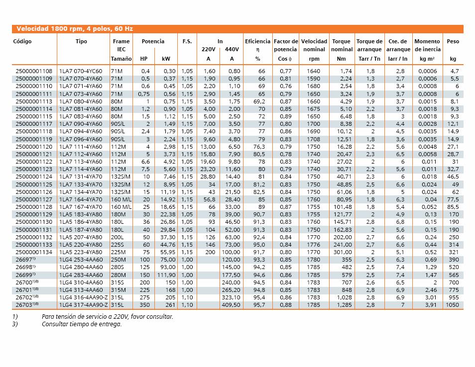
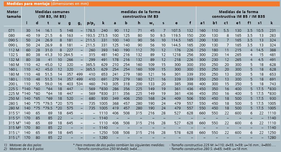
31 C Poly-phase electric motor C.1. Electric motor catalogue

32 Pág. 32 Memoria
33

34 Pág. 34 Memoria
Bombardier Challenger Auxiliary Power Unit
 GENERAL A Honeywell 36 150(CL) constant-speed gas turbine auxiliary power unit (APU) is installed within a fire-resistant compartment in the aft equipment bay. The APU drives a generator, providing AC
ENGINE GROUND RUNNING
 B737 600/700/800/900 (CFM 56) ENGINE GROUND RUNNING Guide and Reference Sheets This publication is for TRAINING PURPOSES ONLY. This information is accurate at the time of completion. No update service
ATA 49 AUXILIARY POWER UNIT
 F900EX EASY 02-49-00 CODDE 1 PAGE 1 / 2 TABLE OF CONTENTS 02-49 02-49-00 TABLE OF CONTENTS 02-49-05 GENERAL Introduction Sources APU location 02-49-10 DESCRIPTION Introduction Description Operating principle
DASSAULT AVIATION Proprietary Data
 F2000EX EASY 02-70-00 CODDE 1 PAGE 1 / 2 TABLE OF CONTENTS 02-70 02-70-00 TABLE OF CONTENTS 02-70-05 GENERAL Introduction Sources Engine location 02-70-10 DESCRIPTION Introduction Major components Operating
GENERAL The Honeywell model TFE731-40AR turbofan engine is a lightweight, two-spool, geared-stage, front-fan, jet engine.
 ENGINE GENERAL The Honeywell model TFE731-40AR turbofan engine is a lightweight, two-spool, geared-stage, front-fan, jet engine. The cross section of the engine is shown in Figure 7-71-1, page VII-71-3.
COMPONENT IDENTIFICATION
 This CFMI publication is for Training Purpose Only. The information is accurate at the time of compilation; however, no update service will be furnished to maintain accuracy. For authorized maintenance
European Aviation Safety Agency
 European Aviation Safety Agency EASA TYPE-CERTIFICATE DATA SHEET Number : IM.E.016 Issue : 07 Date : 21 May 2014 Type : Williams International Co. FJ44 Series Engines s FJ44-1A FJ44-1AP FJ44-2A FJ44-2C
CFM56-7B POWER PLANT REMOVAL & INSTALLATION
 Task No: 737-71-00-00 NG Maint Prog Ref: BAL/BOE/11 Station: A/C Reg: Issue: 5 Date: NOV 2017 A.M.M. Ref: 71-00-02 Check: Aircraft Type CAA App Ref. UK.145.00112 Scheduled / Unscheduled Delete as applicable
CFM REGULATION THE POWER OF FLIGHT
 CFM56-3 3 REGULATION 1 CFM56-3 2 Speed Governing System Fuel Limiting System VBV VSV N1 Vs P Idling System HPTCCV N1 Vs Z N1 Vs T Main Tasks Additional Tasks Corrections MEC PMC CFM 56-3 ENGINE OPERATIONAL
DASSAULT AVIATION Proprietary Data
 F2000EX EASY 02-49-00 CODDE 1 PAGE 1 / 2 TABLE OF CONTENTS 02-49 02-49-00 TABLE OF CONTENTS 02-49-05 GENERAL Introduction Sources Equipment location 02-49-10 DESCRIPTION Introduction Description Operating
TCDS NUMBER E37NE. REVISION: 13* DATE: May 1, 2014 CFM INTERNATIONAL, S.A. MODELS:
 TCDS NUMBER E37NE U.S. DEPARTMENT OF TRANSPORTATION FEDERAL AVIATION ADMINISTRATION TYPE CERTIFICATE DATA SHEET E37NE REVISION: 13* DATE: May 1, 2014 CFM INTERNATIONAL, S.A. MODELS: CFM56-5B1 CFM56-5B1/P
AIRCRAFT SYSTEMS HYDRAULIC
 Intentionally left blank PRELIMINARY PAGES - TABLE OF CONTENTS DSC-29-10 Description DSC-29-10-10 General GENERAL... A DSC-29-10-20 Generation GREEN SYSTEM PUMP...A BLUE SYSTEM PUMPS...B YELLOW SYSTEM
General. APU Control System. APU Door System
 .10 -Description and Operation General The Auxiliary Power Unit () provides electrical and pneumatic power for engine start and air conditioning, and supplies ground and in-flight electrical power. Pneumatic
- (Ref , P. Block 001) - (Ref , P. Block 301) - (Ref , P. Block 301)
 - (Ref , P. Block 301) - (Ref , P. Block 301)") ENGINE PUMP PRESSURE SWITCH 113GK (112GK) REMOVAL/INSTALLATION WARNING: 1. Equipment and Materials CHECK THAT THE LANDING GEAR GROUND SAFETIES INCLUDING WHEEL CHOCKS ARE IN POSITION. BEFORE APPLING OR
ENGINE PUMP PRESSURE SWITCH 113GK (112GK) REMOVAL/INSTALLATION WARNING: 1. Equipment and Materials CHECK THAT THE LANDING GEAR GROUND SAFETIES INCLUDING WHEEL CHOCKS ARE IN POSITION. BEFORE APPLING OR
ATA 36 PNEUMATIC TABLE OF CONTENTS DGT ATA 36 PNEUMATIC TABLE OF CONTENTS GENERAL Introduction Sources
 F900EX EASY 02-36-00 CODDE 1 PAGE 1 / 2 TABLE OF CONTENTS 02-36 02-36-00 TABLE OF CONTENTS 02-36-05 GENERAL Introduction Sources 02-36-10 DESCRIPTION Introduction Main sub-systems Distribution 02-36-15
Canadair Regional Jet 100/200 - Auxiliary Power Unit
 1. INTRODUCTION The auxiliary power unit (APU) is installed within a fireproof titanium enclosure in the aft equipment compartment. The APU is a fully automated gas turbine power plant which drives an
AIRCRAFT SYSTEMS PNEUMATIC
 Intentionally left blank PRELIMINARY PAGES - TABLE OF CONTENTS DSC-36-10 Description DSC-36-10-10 General GENERAL... A DSC-36-10-20 Engine Bleed System GENERAL... A Architecture... B Air Bleed Selection...C
DASSAULT AVIATION Proprietary Data
 FALCON 7X 02-70-05 CODDE 1 PAGE 1 / 6 GENERAL ACRONYMS LIST ACOC AGB APU A/T ATSV BOV CAS CB CL CMC CR DC DCU ECS EEC FADEC FBW FCU FF FOHE FSOV HP HPC HPT IGV ITT LP LPC LPT LRU MV N1 N2 PDU PLA PMA PMU
CHAPTER ICE AND RAIN PROTECTION SYSTEM
 15--00--1 ICE AND RAIN PROTECTION SYSTEM Table of Contents REV 3, May 03/05 CHAPTER 15 --- ICE AND RAIN PROTECTION SYSTEM Page TABLE OF CONTENTS 15-00 Table of Contents 15--00--1 INTRODUCTION 15-10 Introduction
DASSAULT AVIATION Proprietary Data
 F900EX EASY 02-30-00 CODDE 1 PAGE 1 / 2 TABLE OF CONTENTS 02-30 02-30-00 TABLE OF CONTENTS 02-30-05 GENERAL Introduction Anti-icing protection sources Anti-ice system location overview 02-30-10 DESCRIPTION
canadair chzflleriqer OPERATING MANUAL PSP 601A-6 SECTION 5 AUXILIARY POWER UNIT (APU)
") OPERATING MANUAL. AUXILIARY POWER UNIT (APU) 1.. 3. 4. 5. 6. GENERAL APU CONTROL START SYSTEM SHUTDOWN BLEED AIR SYSTEM OIL SYSTEM TABLE OF CONTENTS Page 1 3 3 Figure Number LIST OF ILLUSTRATIONS Title
OPERATING MANUAL. AUXILIARY POWER UNIT (APU) 1.. 3. 4. 5. 6. GENERAL APU CONTROL START SYSTEM SHUTDOWN BLEED AIR SYSTEM OIL SYSTEM TABLE OF CONTENTS Page 1 3 3 Figure Number LIST OF ILLUSTRATIONS Title
European Aviation Safety Agency
 European Aviation Safety Agency EASA TYPE-CERTIFICATE DATA SHEET Number : IM.E.020 Issue : 1 Date : 08 June 2005 Type : Pratt and Whitney PW6000 series engines Variants PW6122A PW6124A List of effective
BD 700 AIRCRAFT MAINTENANCE MANUAL PART II GRAVITY REFUELING - SERVICING
 GRAVITY REFUELING - SERVICING TASK 620 801 1. Use of Fuel Biocide Additive When Gravity Refueling A. Tools and Equipment REFERENCE Pneumatic Injector Shop Air, 90 ±10 psi (620.53 ±68.95 kpa) Test Panel,
Installation Instructions
 010A00 011A00 014A00 SMALL ROOFTOP UNITS TWO POSITION OUTDOOR AIR DAMPER 2to15TONS (50/60 Hz) Installation Instructions TABLE OF CONTENTS PACKAGE CONTENTS... 1 PACKAGE USAGE... 1 SAFETY CONSIDERATIONS...
B737 NG APU REMOVAL / INSTALLATION
 Form No: ENG/5806 A/C Reg: Issue: 01 Check: Date: MARCH 2017 Date: Compiled From: 737 NG AMM CHAPTER Station: 49-11-00 S/No Off: A/C Type Boeing 737 NG S/No On: EQUIPMENT AND MATERIALS: APU CRADLE, FISHPOLE
TCDS NUMBER E00078NE U.S. DEPARTMENT OF TRANSPORTATION REVISION: 3 DATE: April 12, 2011
 TCDS NUMBER E00078NE U.S. DEPARTMENT OF TRANSPORTATION REVISION: 3 DATE: April 12, 2011 FEDERAL AVIATION ADMINISTRATION GENERAL ELECTRIC COMPANY MODELS: TYPE CERTIFICATE DATA SHEET E00078NE GEnx-1B54 GEnx-1B58
TYPE-CERTIFICATE DATA SHEET
 TYPE-CERTIFICATE DATA SHEET No. IM.E.016 issue 10 for FJ44/FJ33 Series Engines Certificate Holder Williams International Co. Walled Lake Michigan 48390-0200 USA For Models: FJ44-1A FJ44-1AP FJ44-2A FJ44-2C
Jump to Table of Contents
 Jump to Table of Contents PIPER AIRCRAFT CORPORATION PA-28R-201, CHEROKEE ARROW III SECTION 3 EMERGENCY PROCEDURES 3.3 EMERGENCY PROCEDURES CHECK LIST ENGINE FIRE DURING
B737 NG APU REMOVAL / INSTALLATION
 Form No: ENG/5806 A/C Reg: Issue: 02 Check: Date: JULY 2018 Date: Compiled From: 737 NG AMM CHAPTER Station: 49-11-00 S/No Off: A/C Type Boeing 737 NG S/No On: EQUIPMENT AND MATERIALS: APU CRADLE, FISHPOLE
Dash8 - Q400 - Pneumatics
 12.19.1 Introduction The Auxiliary Power Unit (APU) replaces the standard composite tailcone with a titanium tailcone and firewall. The APU is accessed by two clamshell type doors on the bottom of the
CARENADO COPYRIGHTS. Normal & Emergency Checklist
 NORMAL PROCEDURES CHECKLIST PREFLIGHT CHECK Control wheel -- RELEASE BELTS Avionics -- OFF Master Switch -- ON Fuel quantity gauges -- CHECK Master switch -- OFF Ignition -- OFF Exterior -- CHECK FOR DAMAGE
INDEX. Preflight Inspection Pages 2-4. Start Up.. Page 5. Take Off. Page 6. Approach to Landing. Pages 7-8. Emergency Procedures..
 INDEX Preflight Inspection Pages 2-4 Start Up.. Page 5 Take Off. Page 6 Approach to Landing. Pages 7-8 Emergency Procedures.. Page 9 Engine Failure Pages 10-13 Propeller Governor Failure Page 14 Fire.
Vso 61. Vs1 63. Vr 70. Vx 76. Vxse 78. Vy 89. Vyse. 89 (blue line) Vmc. 61 (radial redline) Vsse 76. Va 134) Vno 163
 Vmc. 61 (radial redline) Vsse 76. Va 134) Vno 163") PA34-200T Piper Seneca II Normal procedures V-speeds Knots Vso 6 Vs 63 Vr 70 Vx 76 Vxse 78 Vy 89 Vyse Vmc 89 (blue line) 6 (radial redline) Vsse 76 Va 2-36(@4507lbs 34) Vno 63 Vfe 38 (0*)/2(25*)/07(40*)
PA34-200T Piper Seneca II Normal procedures V-speeds Knots Vso 6 Vs 63 Vr 70 Vx 76 Vxse 78 Vy 89 Vyse Vmc 89 (blue line) 6 (radial redline) Vsse 76 Va 2-36(@4507lbs 34) Vno 63 Vfe 38 (0*)/2(25*)/07(40*)
European Aviation Safety Agency
 European Aviation Safety Agency EASA TYPE CERTIFICATE DATA SHEET Number: IM.E.021 Issue: 05 Date: 03 January 2013 Type: General Electric Company CF34-10E Series Engines Variants CF34-10E2A1 CF34-10E5 CF34-10E5A1
TYPE CERTIFICATE DATA SHEET
 TYPE CERTIFICATE DATA SHEET No. IM.E.096 for PW800 Series Engines Type Certificate Holder 1000 Marie Victorin Longueuil, Quebec J4G1A1 Canada For : TE.CERT.00052 001 European Aviation Safety Agency, 2016.
BEFORE START AFTER START
 BEFORE START ENGINE START AFTER START - Version 03 1.a. BEFORE START LOADSHEET...CHECK TAKEOFF DATA..... ENTER/REVISE TAKEOFF DATA... XCHECK COCKPIT DOOR...CLOSED SEAT BELTS ADJUST MCDU...PERF TO SEAT
European Aviation Safety Agency
 European Aviation Safety Agency EASA TYPE CERTIFICATE DATA SHEET Number : IM.E.026 Issue : 03 Date : 04 January 2013 Type : Engine Alliance LLC GP7200 series engines Variants: GP7270 GP7277 List of Effective
European Aviation Safety Agency
 European Aviation Safety Agency EASA TYPE-CERTIFICATE DATA SHEET Number : E.036 Issue : 04 Date : 10 September 2013 Type : Rolls-Royce plc Trent 1000 series engines Models Trent 1000-A Trent 1000-A2 Trent
AIRPLANE OPERATIONS MANUAL SECTION 2-15
 SECTION 2-15 TABLE OF CONTENTS Block General... 2-15-05..01 Bleed Air Thermal Anti-Icing System... 2-15-10..01 Wing, Stabilizer and Engine Anti-icing Valves Operational Logic... 2-15-10..04 EICAS Messages...
CHAPTER 4 ---AUXILIARY POWER UNIT
 Table of Contents Vol. 1 04--00--1 CHAPTER 4 ---AUXILIARY POWER UNIT Page TABLE OF CONTENT 04-00 Table of Contents 04--00--1 INTRODUCTION 04-10 Introduction 04--10--1 POWER PLANT 04-20 APU Power Plant
SECTION 6-3 POWER PLANT
 SECTION 6-3 SYSTEMS DESCRIPTION Index Page General Description... 6-3-3 Engine Features... 6-3-4 Engine Indication System... 6-3-6 Power Plant Control... 6-3-10 Power Plant System Control... 6-3-12 Power
TYPE-CERTIFICATE DATA SHEET
 Issue: 02 & LEAP-1C series engines Date: 11 March 2016 TYPE-CERTIFICATE DATA SHEET No. E.110 for Engine & LEAP-1C series engines Type Certificate Holder SA SA 2, boulevard du Général Martial Valin 75015
DEPARTMENT OF TRANSPORTATION FEDERAL AVIATION ADMINISTRATION
 DEPARTMENT OF TRANSPORTATION FEDERAL AVIATION ADMINISTRATION E4WE Revision 34 HONEYWELL (AlliedSignal, Garrett, AiResearch) TPE331-3 TPE331-8 TPE331-10N TPE331-11U TPE331-3U TPE331-8A TPE331-10P TPE331-11UA
Introduction. APU Location
 B737 NG APU Introduction The auxiliary power unit (APU) is a self contained gas turbine engine installed within a fireproof compartment located in the tail of the airplane. The APU supplies bleed air for
Preflight Inspection Cabin EMPENNAGE RIGHT WING Trailing Edge RIGHT WING NOSE
 Preflight Inspection Cabin 1. Control Wheel Lock REMOVED 2. Ignition Switch OFF 3. Avionics Power Switch OFF 4. Master Switch ON 5. Fuel Quantity Indicators CHECK QUANTITY 6. Master Switch OFF 7. Fuel
canaaair chaiiencjer
 canaaair chaiiencjer AUXILIARY POWER UNIT (APU) TABLE OF CONTENTS Subject Page GENERAL APU CONTROL START SYSTEM SHUTDOWN I BLEED AIR SYSTEM OIL SYSTEM 1 1 3 5 5 7 Figure Number LIST OF ILLUSTRATIONS Title
Pneumatic Air Conditioning System Citation, Citation I
 Pneumatic Air Conditioning System Citation, Citation I COCKPIT VENT FOOT WARMER OVERHEAD COCKPIT WINDSHIELD WEMAC OPTIMAL VENT OVERHEAD CONDITIONED AIR DUCTS BLOWER SIDE WINDOW UNDER FLOOR CONDITIONED
Cessna 172P PPL Checklist Page 1
 Cessna 172P PPL Checklist 06-08-2017 Page 1 Cessna 172P PPL Checklist 06-08-2017 Page 2 Checklist Items Informational Items Critical Memory Items PREFLIGHT COCKPIT CHECK (DO-LIST) Pitot Cover -- REMOVE
C I R R U S DISTRIBUTION DESCRIPTION
 MODELS SR AND SRT DISTRIBUTION. DESCRIPTION This section contains information on the distribution system. The fuel distribution system consists of electric and mechanical (engine-driven) fuel pumps, fuel
4A.2 AIRSPEEDS FOR NORMAL OPERATING PROCEDURES
 Normal Operating DA 40 AFM 4A.1 INTRODUCTION Chapter 4A contains checklists and describes extended procedures for the normal operation of the airplane. 4A.2 AIRSPEEDS FOR NORMAL OPERATING PROCEDURES Flight
A AMM - KRUEGER FLAP ACTUATOR - REMOVAL/INSTALLATION
 FED ALL WARNING : 1. Equipment and Materials KRUEGER FLAP ACTUATOR - LANDING GEAR - MAKE SURE THAT THE GROUND SAFETIES AND CHOCKS ARE IN POSITION. FLIGHT CONTROLS - MAKE SURE THAT THE GROUND SAFETIES AND
CIRRUS AIRPLANE MAINTENANCE MANUAL
 1. GENERAL This chapter contains information on the storage, distribution, and indicating components of the fuel system. The engine is supplied with fuel drawn out of the left or right integral fuel tank
DEPARTMENT OF TRANSPORTATION FEDERAL AVIATION ADMINISTRATION TYPE CERTIFICATE DATA SHEET NO. 1E8
 DEPARTMENT OF TRANSPORTATION FEDERAL AVIATION ADMINISTRATION 1E8 Revision 18 PRATT & WHITNEY AIRCRAFT TURBO WASP JT3D-1 JT3D-3 JT3D-1A JT3D-3B JT3D-1-MC6 JT3D-3C JT3D-1A-MC6 JT3D-7 JT3D-1-MC7 JT3D-7A JT3D-1A-MC7
32 quarts Transmission Allison HT 740 Automatic Fluid
 BOOK: Blue Book I SECTION: E-One Engine (SGT) Page 1 of 6 E-ONE CYCLONE TABLE OF CONTENTS SPECIFICATIONS... 2 DAILY CHECKS... 2 SAFETY CHECKS... 3 START ENGINE... 3 STOP ENGINE... 3 EMERGENCY SHUTDOWN
canadair chaifenqer 14-CONTENTS Page 1 Feb 12/88 TABLE OF CONTENTS Subject Page GENERAL ICE DETECTION
 chaifenqer ICE/RAIN PROTECTION TABLE OF CONTENTS Subject Page GENERAL ICE DETECTION WING ANTI-ICING General Operating Modes System Monitoring Lower Isolation Valve Operation ENGINE ANTI-ICING General Operation
Dash8-200/300 - Auxiliary Power Unit APU CONTROLS AND INDICATORS. Page 1
 APU CONTROLS AND INDICATORS Page 1 APU control and indicators Page 2 closed APU controls and indicators Page 3 SYSTEM DESCRIPTION General The auxiliary power unit (APU) is a gas turbine engine, located
A AMM - ENGINE BLEED AIR SUPPLY SYSTEM - DESCRIPTION AND OPERATION
 ENGINE BLEED AIR SUPPLY 1. General The system is designed to : - select the compressor stage from which air is bled, depending on the pressure and/or temperature existing at the last stage of the engine
United States Army Aviation Center of Excellence. Fort Rucker, Alabama JULY 2011 STUDENT HANDOUT
 United States Army Aviation Center of Excellence Fort Rucker, Alabama JULY 2011 STUDENT HANDOUT TITLE: AH-64D INTEGRATED PRESSURIZED AIR SYSTEM (IPAS) FILE NUMBER: 011-0910-1.5 (LOT13) PROPONENT FOR THIS
CHAPTER 11. Page TABLE OF CONTENTS /02 DESCRIPTION. General Description Controls and Indicators
 CHAPTER 11 FUEL SYSTEM Page TABLE OF CONTENTS 11-00-01/02 DESCRIPTION General 11-10-01 Description 11-10-01 Controls and Indicators 11-10-02 COMPONENTS (NOT USED) CONTROLS AND INDICATORS 11-30-01 FUNCTIONAL
United States Army Warfighting Center Fort Rucker, Alabama NOVEMBER 2006
 United States Army Warfighting Center Fort Rucker, Alabama NOVEMBER 2006 STUDENT HANDOUT TITLE: CH-47D ENGINE CONTROL SYSTEM FILE NUMBER: 011-2109-3 PROPONENT FOR THIS STUDENT HANDOUT IS: 110 th Aviation
BEFORE START AFTER START
 BEFORE START ENGINE START AFTER START A340 - Version 03b 1.a. BEFORE START LOADSHEET...CHECK TAKEOFF DATA..... ENTER/REVISE TAKEOFF DATA... XCHECK COCKPIT DOOR...CLOSED SEAT BELTS ADJUST MCDU...PERF TO
Engine Performance Analysis
 Engine Performance Analysis Introduction The basics of engine performance analysis The parameters and tools used in engine performance analysis Introduction Parametric cycle analysis: Independently selected
CIRRUS AIRPLANE MAINTENANCE MANUAL MODELS SR22 AND SR22T CHAPTER 28-00: FUEL GENERAL. Fuel 28-00: FUEL. 1. General
 CIRRUS AIRPLANE MAINTENANCE MANUAL Fuel CHAPTER 28-00: GENERAL 28-00: 1. General This chapter contains information on the storage, distribution, and indicating components of the fuel system. The engine
Fokker 50 - Limitations GENERAL LIMITATIONS MASS LIMITATIONS. Page 1. Minimum crew. Maximum number of passenger seats.
 GENERAL LIMITATIONS Minimum crew Cockpit: Two pilots Maximum number of passenger seats Sixty-two (62) Maximum operating altitudes Maximum operating pressure altitude: Maximum take-off and landing pressure
AIRCRAFT SYSTEMS POWER PLANT
 Intentionally left blank PRELIMINARY PAGES - TABLE OF CONTENTS DSC-70-10 Engine GENERAL... A DESCRIPTION...B DSC-70-20 Fadec GENERAL... A ARCHITECTURE... B FUNCTIONS...C Power Supply...D DSC-70-30 Thrust
DESIGNATION. (1) Access Platform, 3.0 m (10 ft.) (2) 98A Guard - Safety, Flap/Slat Ctl Lever. (6) Circuit Breaker Safety Clips and Tags
 Access Platform, 3.0 m (10 ft.) (2) 98A Guard - Safety, Flap/Slat Ctl Lever. (6) Circuit Breaker Safety Clips and Tags") KRUEGER FLAP HYDRAULIC ACTUATION - ADJUSTMENT/TEST CHECK THAT THE LANDING GEAR GROUND SAFETIES INCLUDING WHEEL CHOCKS ARE IN POSITION. BEFORE APPLYING OR RELIEVING HYDRAULIC SYSTEM PRESSURE, MAKE CERTAIN
KRUEGER FLAP HYDRAULIC ACTUATION - ADJUSTMENT/TEST CHECK THAT THE LANDING GEAR GROUND SAFETIES INCLUDING WHEEL CHOCKS ARE IN POSITION. BEFORE APPLYING OR RELIEVING HYDRAULIC SYSTEM PRESSURE, MAKE CERTAIN
THOMSON AIRWAYS LIMITED DISCREPANCY SHEET
 IPC REF FIG ITEM DESCRIPTION FROM 72.35.01 01 085/220 ROTATING FAIRINGS 72.31.11 01 280 LP BLADES (22 OFF) 73.11.07 01 645/725 MAIN FUEL INLET TUBE 29.11.03 02 100 HYD. SUPPLY,RIGID TUBE 29.11.03 02 200
CIRRUS AIRPLANE MAINTENANCE MANUAL
 POWER PLANT 1. GENERAL This chapter describes maintenance practices for the airplane systems which provide the means to induce and convert fuel-air mixture into power such as the engine, baffling, cowling,
Single Stage Rotary Vane Vacuum Pump Installation and Operation Manual RX-10 RX-21 RX-25
 V acuum Pumps Single Stage Rotary Vane Vacuum Pump Installation and Operation Manual RX-10 RX-21 RX-25 www.republicsales.com Revised 10.14 2014 Republic Sales & Manufacturing Single Stage Rotary Vane Vacuum
CAVOK Aviation Training Ltd. Cessna C177
 CAVOK Aviation Training Ltd. Cessna C177 1. Pre Flight Inspection In the Cabin o Aircraft Documents... CHECKED o Battery... ON Fuel Quantity... CHECKED LND GEAR Lever... DOWN, Green Light Flaps... 20 o
DASSAULT AVIATION Proprietary Data
 F2000EX EASY 02-28-00 CODDE 1 PAGE 1 / 2 TABLE OF CONTENTS 02-28 ATA 28 - FUEL SYSTEM 02-28-00 TABLE OF CONTENTS 02-28-05 GENERAL Introduction Sources Fuel tank location 02-28-10 DESCRIPTION Sub-systems
POWER GENERATION SYSTEMS
 POWER GENERATION SYSTEMS The Power Generation Systems on HI 595 CF&D consist of three Waukesha 7042 gas driven generators and two diesel driven generators. Two of the three Gas Generators must run to provide
Chapter 11 Safety, Ground Ops, Servicing
 Chapter 11 Safety, Ground Ops, Servicing Chapter 11 Section A Study Aid Questions 1. Keeping hangars, shop, and the flight line and is essential to safety and efficient maintenance. 2. and should watch
CHAPTER 21 ENVIRONMENT CONTROL. Section Title Page
 CHAPTER 21 ENVIRONMENT CONTROL Section Title Page 21-00 Description........................................ 21.1 21-10 Ventilation........................................ 21.3 21-11 Nose Vent................................
RELEASING PRESSURE IN THE HYDRAULIC SYSTEM,
 Testing And Adjusting Introduction NOTE: For Specifications with illustrations, make reference to SPECIFICATIONS for 225 EXCAVATOR HYDRAULIC SYSTEM, Form No. SENR7734. If the Specifications are not the
SECTION 5 AUXILIARY POWER UNIT (APU) TABLE OF CONTENTS LIST OF ILLUSTRATIONS. Title
 TABLE OF CONTENTS LIST OF ILLUSTRATIONS. Title") BOMBARDIER AUXILIARY POWER UNIT (APU) TABLE OF CONTENTS Subject GENERAL APU CONTROL START SYSTEM SHUTDOWN BLEED AIR SYSTEM OIL SYSTEM Page 1 1 4 6 8 8 LIST OF ILLUSTRATIONS Figure Number 1 APU Control
BOMBARDIER AUXILIARY POWER UNIT (APU) TABLE OF CONTENTS Subject GENERAL APU CONTROL START SYSTEM SHUTDOWN BLEED AIR SYSTEM OIL SYSTEM Page 1 1 4 6 8 8 LIST OF ILLUSTRATIONS Figure Number 1 APU Control
Induction, Cooling, & Exhaust. Aviation Maintenance Technology 111 B B
 Induction, Cooling, & Exhaust Aviation Maintenance Technology 111 B - 112 B Unliscensed copyrighted material - W. North 1998 Unliscensed copyrighted material - W. North 1998 Induction = those locations
Single Stage Rotary Vane Vacuum Pump Installation and Operation Manual RX-40 RX-63 RX-100
 V acuum Pumps Single Stage Rotary Vane Vacuum Pump Installation and Operation Manual RX-40 RX-63 RX-100 www.republicsales.com Revised 02.15 2015 Republic Sales & Manufacturing Single Stage Rotary Vane
I. DISPATCH PLANNING & AIRCRAFT EXTERIOR CHECK
 SCHODACK AVIATION Page 1 of 10 I. DISPATCH PLANNING & AIRCRAFT EXTERIOR CHECK 1. Flight Planning 1. Aircraft requirements & preparation: Required aircraft documents: Airworthiness Certificate Registration
PREFLIGHT CHECK COCKPIT RIGHT WING. NORMAL PROCEDURRES CHECKLIST PA-28RT 201 Arrow IV
 NORMAL PROCEDURRES CHECKLIST PA-28RT 201 Arrow IV PREFLIGHT CHECK COCKPIT Control Wheel -- Release Restraints Avionics -- OFF Parking Brake -- SET All Switches -- OFF Mixture -- IDLE CUT-OFF Master Switch
INDEX: Normal Procedures Emergency Procedures Pre Flight Inspection NORMAL PROCEDURES BEFORE STARTING ENGINE
 INDEX: Normal Procedures Emergency Procedures Pre Flight Inspection NORMAL PROCEDURES BEFORE STARTING ENGINE 1. Preflight Inspection -- COMPLETE 2. Seats, Belts, Shoulder Harnesses -- ADJUST and LOCK 3.
CHAPTER 4 ---AUXILIARY POWER UNIT
 Vol. 1 04--00--1 AUXILIARY POWER UNIT Table of Contents REV 3, May 03/05 CHAPTER 4 ---AUXILIARY POWER UNIT Page TABLE OF CONTENT 04-00 Table of Contents 04--00--1 INTRODUCTION 04-10 Introduction 04--10--1
I. DISPATCH PLANNING & AIRCRAFT EXTERIOR CHECK
 SCHODACK AVIATION Page 1 of 10 I. DISPATCH PLANNING & AIRCRAFT EXTERIOR CHECK 1. Flight Planning 1. Aircraft requirements & preparation: 1. Required aircraft documents: 1. Airworthiness Certificate 2.
Service Bulletin No.: DAC Rev 5 Date Issued: 26 November 2010 Title: Engine Fuel System Conversion from IO-240-B17B to IO-240-B3B
 Page: 1 of 10 1. ATA Code: 7300 2. Effectivity: DA20-C1 S/N C0380 to C0456, C0467 to C0471, C0482 to C0488, C0496, C0497, C0504, C0505, C0511 to C0513 and C0536 or earlier aircraft on which SB DAC1-73-01
TYPE-CERTIFICATE DATA SHEET
 TYPE-CERTIFICATE DATA SHEET No. E.003 for Type Certificate Holder CFM International SA 2, boulevard du Général Martial Valin F-75724 Paris Cedex 15 France For Models: CFM56-5B SAC CFM56-5B DAC CFM56-5C
GENERAL The AuRACLE Engine Management System primary display provides a graphical representation of the following engine instrumentation:
 GENERAL The AuRACLE Engine Management System primary display provides a graphical representation of the following engine instrumentation: o Manifold Pressure (MAP) o RPM o Fuel Flow (FF) o Turbine Inlet
A AMM - MAIN GEAR SPHERICAL BEARING - REMOVAL/INSTALLATION
 MAIN GEAR SPHERICAL BEARING - 1. Equipment and Materials CHECK THAT THE LANDING GEAR GROUND SAFETIES INCLUDING WHEEL CHOCKS ARE IN POSITION. BEFORE APPLYING OR RELIEVING HYDRAULIC SYSTEM PRESSURE, MAKE
Elmendorf Aero Club Aircraft Test
 DO NOT WRITE ON THIS TEST JAN 2014 Elmendorf Aero Club Aircraft Test SENECA II For the following questions, you will need to refer to the Pilots Information Manual for the PA-34-200T. USE ANSWER SHEET
SECTION 2-14 PNEUMATICS, AIR CONDITIONING AND PRESSURIZATION
 AIRPLANE PNEUMATICS SECTION 2-14 PNEUMATICS, TABLE OF CONTENTS Block General... 2-14-05..01 Pneumatic System... 2-14-05..02 Pneumatic System Function Logic... 2-14-05..06 Cross Bleed Valve Operational
TYPE-CERTIFICATE DATA SHEET
 TYPE-CERTIFICATE DATA SHEET No. IM.E.054 for Engine GE Honda Aero Engines Series Engine Type Certificate Holder 9050 Centre Pointe Dr Suite 200 West Chester, OH 45069 Unites States of America For s: TE.CERT.00052-001
DC3Training.com N28AA DC-3 Pilot s Handbook
 SECTION 9 FUEL SYSTEM Index General page 2 Operation page 5 Limitations page 6 Troubleshooting page 6 5/15/2012 crew@dc3training.com 1 GENERAL A. Fuel Tanks The dual fuel system has a total capacity of
CHAPTER 12 SERVICING. Section Title Page
 CHAPTER 12 SERVICING Section Title Page 12-10 Main Rotor Gearbox.................................. 12.1 12-11 Servicing................................. 12.1 12-12 Filter Replacement...........................
SD3-60 AIRCRAFT MAINTENANCE MANUAL PROTECTION DESCRIPTION & OPERATION
 SD3-60 AIRCRAFT MAINTENANCE MANUAL z AMM 31.0.0.0COLD WEATHER PROTECTION DESCRIPTION & OPERATION 1. General This section details precautions necessary to protect the aircraft on the ground during cold
EMBRAER 190. Powerplant DO NOT USE FOR FLIGHT
 EMBRAER 190 Powerplant DO NOT USE FOR FLIGHT Embraer 190 - Systems Summary [Powerplant] Two wing-mounted General Electric CF34-10E engines produce power to the EMBRAER 190. The General Electric CF34-10E
General. Airfoil Anti-Ice System
 General Ice.10 Ice and Rain Protection-Description and Operation Ice and rain protection consists of: Airfoil (wing and tail) anti-ice systems. Engine cowl anti-ice system. Air data heater system (pitot,
CESSNA 182 CHECKLIST. LEFT WING Trailing Edge 1. Aileron CHECK freedom of movement and security
 CESSNA 182 CHECKLIST PRE-FLIGHT INSPECTION CABIN 1. Pilot s Operating Handbook AVAILABLE IN THE AIRPLANE (A.R.R.O.W.E) 2. Landing Gear Lever DOWN 3. Control Wheel Lock REMOVE 4. Ignition Switch OFF 5.
AVIATION UNIT AND AVIATION INTERMEDIATE TROUBLESHOOTING MANUAL CH-47D HELICOPTER
 TECHNICAL MANUAL AVIATION UNIT AND AVIATION INTERMEDIATE TROUBLESHOOTING MANUAL CH-47D HELICOPTER This copy is a reprint which includes current pages from Changes 1 through 10. HEADQUARTERS, DEPARTMENT
If, nonetheless, an emergency does arise, the guidelines given here should be followed and applied in order to clear the problem.
 3.1 INTRODUCTION 3.1.1 GENERAL This Chapter contains checklists as well as the description of recommended procedures to be followed in the event of an emergency. Engine failure or other airplane-related
TURBOCHARGER Toyota Celica DESCRIPTION OPERATION TURBOCHARGING SYSTEMS All Models
 TURBOCHARGER 1988 Toyota Celica 1988 TURBOCHARGING SYSTEMS All Models DESCRIPTION Most models use a water-cooled turbocharger, mounted directly to the exhaust manifold with a wastegate assembly attached
GIV MEMORY FLASH CARDS OCT09
 OCT09 GIV MEMORY FLASH CARDS Copyright 2009, FlightSafety International, Inc. Unauthorized reproduction or distribution is prohibited. All rights reserved. INSERT LATEST REVISED CARDS, DESTROY SUPERSEDED