EQUIPMENT Operation Manual. Loctite DuraPump Meter Mix System Part Numbers
|
|
|
- Morgan Douglas
- 5 years ago
- Views:
Transcription
1 EQUIPMENT Operation Manual Loctite DuraPump Meter Mix System Part Numbers
2 Table of Contents 1 Please Observe the Following Emphasized Sections For Your Safety Unpacking and Inspection Items Supplied Features Usage 4 2 Description 4 3 Technical Data 5 4 Installation 5 5 Operation Getting Acquainted with the Control Screens Ratio Check Procedure Purging the Dispense System Machine Cycling Volume Compensation Connecting a Machine Mounted Valve Connecting a Hand Held valve Machine Shut Down 19 6 Program Storage & Recall Storing a Program Recalling a Program 20 7 Troubleshooting Machine is off-ratio Machine will not go to the Setup screen Cycling is too fast or too slow Pumps are leaking material Machine will not cycle 22 8 Care and Maintenance Replacing the Pumps 23 1
3 8.2 Replacing the Pumps Seals Replacing the Mix-Block Check Valves 25 9 Accessories and Spare Parts Exploded Diagrams Parts List Electrical & Pneumatic Diagrams Warranty 39 2
4 1 Please Observe The Following 1.1 Emphasized Sections Warning! Refers to safety regulations and requires safety measures that protect the operator or other persons from injury or danger to life. Caution! Emphasizes what must be done or avoided so that the unit or other property is not damaged. Notice: Gives recommendations for better handling of the unit during operation or adjustment as well as for service activities. 1.2 For Your Safety For safe and successful operation of the unit, read these instructions completely. If the instructions are not observed, the manufacturer can assume no responsibility. Do not use the Unit to dispense flammable products. Do not expose the connecting cable to heat, oil, or sharp edges. Make sure the Unit sits stable and secure. Use only original equipment replacement parts. Do not operate the Unit in excess of 20 cycles per minute. Always disconnect the power supply before servicing the unit. Observe general safety regulations for the handling of chemicals such as Loctite adhesives and sealants. Observe the manufacturer s instructions as stated in the Material Safety Data Sheet (MSDS). While under warranty, the unit may be repaired only by an authorized Loctite service representative. 1.3 Unpacking and Inspection Carefully unpack the Loctite DuraPump Meter Mix Machine and examine the items contained in the carton. Inspect the unit for any damage that might have occurred in transit. If such damage has occurred, notify the carrier immediately. Claims for damage must be made by the consignee to the carrier and should be reported to the manufacturer. 3
5 1.4 Items supplied Meter-Mix Dispense System Night cap and nut assembly Ratio check and nut assembly Footswitch Machine manual 1.5 Features Touch-screen control Linear position encoder Pneumatic or electric cycle start Inlet feed pressure to 1500 PSI 1.6 Usage Use with bulk (non-cartridge packaged) 2-part adhesives such as epoxies, and urethanes 2 Description The Loctite DuraPump Meter Mix System is a bench style, Two-part adhesive dispenser. It can effectively dispense epoxy, urethane, and silicone products. The system is based on Rod metering; whereas, precision rods displace a volume of product during a cycle. A full stroke of the metering rods can yield 28cc (1:1). Depending on the product, dose shots as small as 0.4cc can be achieved. The unit can be connected to receive product from a number of different feed types and can accept pressures up to 1,500 PSI. The system PLC controls all dispense functions; available between single dose, incremental and continuous modes. A linear encoder provides selectable, precision dispensing of adhesive volumes. The system is designed to be cycled by electric or a remote triggered pneumatic hand held valve. The system can also be actuated by a signal from a remote control system, and features a Ready/Busy output signal to interface with other dispense/control equipment. 4
6 3 Technical Data Dimensions (L x H x W): Total weight: Operating voltage: Power consumption: Product inlet port approx. 12 1/2 W x 15 D X 27 H 85 lbs VAC 50/60Hz 1 Amp ½ NPT (f) Power Cord: Pneumatic inlet: Metered Volume Standard 120VAC 1/4 NPT Ratio Full Stroke 1:1 28 ml 2: ml 4:1 18 ml 10: ml 4 Installation Before using the dispense system for the first time check it carefully for signs of external damage. If any shipping damage is found DO NOT USE THE MACHINE - return it to your supplier immediately. 1. Place the MMD machine on a bench or other stable location appropriate for the dispense system. Ensure the machine is on a sturdy surface and can handle the weight and process actions required of the dispense unit. Use the leveling feet of the machine as necessary. 2. Connect a pneumatic supply to the pneumatic inlet fitting at the rear of the machine. Ensure a steady supply of 80 PSI minimum. 3. A product feed system can be now connected to the unit. 4. Connect the electrical plug of the MMD machine to an available 120 VAC outlet. 5
 or attach the desired dispense valve (with hoses). The mix-block assembly can be used with product viscosities of 2,000 cps and higher.")
7 Low Level A and B Air Inlet Cycle Pressure Regulator Electrical Outlet Cycle Start On/Off Switch 5 Operation Prepare the machine for use: 1. Use the optional product mix-block ( ) or attach the desired dispense valve (with hoses). The mix-block assembly can be used with product viscosities of 2,000 cps and higher. Mix Block Purge Plugs 2. Connect the feed systems to the MMD machine. 3. Pour or pressurize the products to the MMD machine. Check for any leaks and repair connections if necessary. Fill the Metering Pump s grease reservoir to extend the life of the pump seals and maintain an air tight seal. Grease frequently when using filled materials or abrasives. Use a standard grease gun and a inert, silicone, or Loctite Food Grade grease. 4. Rod Extension Forks are installed on all machines. If product A or B are (sufficiently) pressurized (around 250 PSI, about 125 PSI if using MMA seals), the Fork can be removed. This fork is used to pull down the Displacement Rod during a re-charge. Removing the Fork allows the product pressure to extend the metering rod and thus prevent cavitation or air entrapment (see caution section 7.1). 6
8 Slide Assembly Rod Extension Fork Rod Locking Nut Do not allow the machine to cycle dry (without product). Excessive ball valve wear or damage could result. 5. Place the machine in RUN Mode and select the dispense parameters (see section 5.1 and 5.4). Have a waste cup ready. Cycle the machine until product begins to come out of the dispense nozzle. 6. Adjust the overall cycle rate with the pressure regulator at the rear of the machine. 7. Use a flat tip screwdriver to adjust the DISPENSE rate by turning the top flow control on the Main Actuator (CW for slower; CCW for faster); accessible via panel holes on the right side of the machine. Do not allow the machine to recharge at a faster rate than the product can feed into the pumps. Excessive recharge rates could cause air pockets and out off ratio conditions. Dispense Control Fill Control 8. Adjust the pumps Fill (re-charge) rate by adjusting the bottom flow control on the main actuator (CW for slower; CCW for faster); accessible via panel holes on the right side of the machine. 9. Once the purge procedure is completed, perform a ratio check procedure. 7
9 10. If your machine is using the Rod Extension Forks (mentioned in item 4) do not install a static mix nozzle on the machine until the ratio is validated. This is to ensure that product is flowing properly into (and out of) the metering pumps. 11. The machine is ready for use. Use the incremental run mode whenever possible. Recommended when the dispense dose is less than half of the machine s full stroke amount (see Technical Section for ratio/volume metrics. This will reduce the wear and tear of the machine. Do not use incremental mode if either Part A or B products have a viscosity less than 2,000 cps and you are not using an actuated dispense valve. Maintain the adhesive two components separate from each other at all times. Keep the nozzle area clean after each use to prevent curing. 5.1 Getting acquainted with the control screens The DuraPump has 4 main user screens to operate the machine. Two user screens are for programs and sequences. Two other screens are available for machine servicing: Manual (for servicing) and Configuration for initial ratio or remote operation designation. Most blacked-out areas are active key locations, touch the area to bring-up a keypad (or toggle) to change the value and press the Enter ( ) key. A description of these screens follow: 8
10 1. The RUN Screen comes into view during normal operation. A number at the top left corner of the screen indicates the program the machine is currently running. The active program will be the last program the machine was running. This screen gives access to the setup screen. Touch the Dose box to reset the cycles counter. a. The RUN screen contains a feature that permits the monitoring of the dispense time during a machine cycle. This feature can be enabled during setup (of the program number), and then given an expected 9
11 percentage above and below a good dispense dose. If a dispense cycle takes longer or shorter than the allotted time, and ERROR screen will appear alerting of the incident. b. To enable the Monitor; go to the program setup screen and tap the Dispense Monitor Bar. Tap the disable block and enter a tolerance. The last dispense time is already displayed on the left side of the screen (as reference). c. On error, the RUN screen will change to a red screen alerting an Out of Range condition. The machine will beep and continue to do so, until the user resets by tapping the screen. 2. The SETUP screen is used to select the desired operating mode and dispense parameters. This screen also leads to the program manager to store and recall programs and set the Auto Purge mode parameters. In addition, this screen leads to setup#2 which is where volume compensations can be made. a. To access the Setup screen from the Run mode, touch the setup key at the top of the Run screen. A supervisory lock-out pop-up screen will appear. To enter the setup mode, touch the lower left hand corner of that lock-out screen. A beep will sound; hold this position for a second and the machine will go into setup mode. Supervisory lock-out will occur every time the setup key is pressed. b. In Single, and Incremental Modes, enter a desired dose volume. Select Auto Purge mode function on or off as required. 3. SETUP 2 is a means to get closer to the actual volume that is being dispensed versus what is manually keyed in; see section PROGRAM MANAGER is utilized to load or recall a previously loaded (used) program. A program can also be copied using SAVE AS. The copied program can then be loaded and edited with new changes if so desired. 5. AUTO PURGE screen permits automatic dispensing of a selectable volume of material at a specified time interval (of machine idleness) in order to prevent curing or viscosity increase in the static mix nozzle. 6. SEQUENCE RUN is a feature that allows a series of (up to 10) programs to run consecutively (or serially). Up to 16 different sequences can be stored in the machine (A to P). Programs can be arranged in any manner, including repeating programs. 10
, the Sequence Mode is disabled. 7.")
12 If the SEQUENCE title is touched, the screen will display the RUN screen of the program high-lighted in the sequence (for viewing only). Hit the back key to return to sequence RUN screen. This is useful to remind the user of the contents of a program. Forward Key Back Key If the Remote Mode is enabled (from the Configuration screen), the Sequence Mode is disabled. 7. SEQUENCE SETUP allows a (serial) sequence of programs to be loaded in up to 10 positions. A zero is seen as a reset (back to the start of the sequence). a. The sequence is loaded using the sequence setup screen. The programs selected to run in a sequence should have already been setup and tested. b. The machine waits for a cycle start signal. The 1 st program of the sequence is performed after the cycle (start) signal is detected. c. The machine waits for another trigger; the second program in the sequence is performed, and so on, until the sequence runs into a (0) 11
, if a particular program needs to be run")
13 zero this means to go back to the beginning of the sequence or runs the last of the 10 positions on the sequence. d. During idle periods, the user may jog back to a particular sequence program number (by using the (Forward and Back arrow keys on the sequence RUN screen), if a particular program needs to be run again or skipped. When the next start trigger is received, the highlighted program number will be performed. 8. REMOTE mode allows a PLC connection to the 9-pin sub-d connector for program loading and program execution from a remote control device typically a PLC. a. This function has to be enabled by entering the SERVICE mode during power-up. b. Pins 1 and 9 on the connector (typical footswitch connection) are used to load (a program) and cycle-start the machine (contact closure creates the pulse). c. Any pulse that is longer than 200 ms is considered a cycle start (on whichever program happens to be loaded on the machine). i. There are 2 techniques to load programs. ii. Single count loading uses 50 ms pulses, followed by 50 ms of NO pulse to count to the desired program. Three pulses (with 50 ms no signal in between) loads program #3. iii. Decimal count loading uses 50 ms (short pulses= units) and 150 ms (long pulses= tenths). Program 21 loads with 1 short pulse and 2 long pulses (with 50 ms NO pulse in between all pulses. iv. The machine is always in read mode (when not in cycle); it will continue adding up pulses (even after a long idle period). The adding of pulses ends after a long (200 ms pulse) is received. 12

14 If the Remote Mode is enabled (from the Configuration screen), the Sequence Mode is disabled. The machine is ALWAYS in READ mode (after a cycle). Even if counts were received 10 minutes ago and 5 hours later more counts are received, the machine will continue to add the counts. ONLY a long pulse (200 ms or greater) will load (the final count) and run the program. 9. The MANUAL screen is used for machine service and troubleshooting. This feature is also useful to cycle the Pump Actuator and 3-Way Ball Valve when removing pumps for servicing or looking at the status of inputs to the machine. 13

15 5.2 Ratio Check Procedure This procedure is to ensure that the dispensed material is mixing at the proper ratio, to ensure that when the product goes through the mix nozzle, the adhesive will set and maintain proper bond strength. Ensure that both Part A and B are products are entering the metering pumps. If necessary remove lines or hoses from the DuraPumps s product outlet ports (or remove mixing valve) and check machine cycling to ensure smooth and even flow of product when the machine is cycled. If the machine is cycling faster than the pumps can be filled, an off-ratio condition will occur. 1. Install a ratio check cap on the dispense nozzle. If your valve type does not permit installing a ratio cap; you may be required to remove the valve and take samples at the end of the lines or hoses. 2. Use two small cups or dishes (one for each part) to capture the dispense volume. Weigh each empty cup and record. 3. Perform a single dose cycle on the MMD machine and capture the dispense amounts on the cups. 4. Weigh each cup. Calculate the actual weight of the product on the cups. 14
16 5. Divide the weight of Part A by the specific gravity of Part A product; do the same for Part B this is the volume dispense for each. 6. Divide Part A volume by Part B volume this is your ratio. 5.3 Purging the Dispense System Purging becomes necessary when using the machine for the first time, the dispense path has been disconnected, or air has been introduced into the system. Purging is also a means to zero-in on the dispense ratio if the calculated ratio is slightly off from where it needs to be. 1. The machine should be ready for normal cycling. 2. Remove the static mix nozzle from the dispense valve. 3. Set the machine to Continuous Mode. 4. Have a waste cup on hand to capture the dispensed product. 5. Cycle the machine until an uninterrupted (no air, burping) of product occurs. 6. The purging will vary depending on the application, length of dispense hoses, and the length of product feed lines. Estimate the amount of product purge required according to the manner in which your MMD machine product path is connected. If an off-ratio condition exists, it may be necessary to purge the mixblock assembly or dispense valve and hoses (as applicable). 1. Remove the pipe plugs at the top of each end cap on the mix block assembly (be prepared to capture product (both from the mix-block and from the purge holes at the top of the mix block). 2. Reduce the cycle rate of the machine (excessive recharge rate can cause off ratio condition). 3. Cycle the machine until no air bubbles can be seen coming out of the top of the purge hole. 4. Re-install the plugs, perform a ratio check and setup the machine for production if the ratio is good. 5.4 Machine Cycling This MMD machine is capable of operating in three (run) modes (green screens) and two maintenance modes (red/orange screens). To change any operating mode, SETUP must be selected (refer to 5.1), change operating mode; then press exit. The machine will operate with the parameters that are active when exiting the setup mode. 1. Single Dose This mode will cause the machine to cycle for the volume of product selected and then re-charge (refill) the pumps. In this mode, it is 15
17 possible to select a volume larger than a full stroke. For example, an 80 ml dose can be selected and the machine will cycle the number of times required to achieve the volume (and then returns to the Home position). Use the incremental run mode whenever possible. Recommended when the dispense dose is less than half of the machine s full stroke amount. This will reduce the wear and tear of the machine. Do not use incremental mode if either Part A or B products have a viscosity less than 2,000 cps and you are not using an actuated dispense valve. 2. Incremental This mode will cause the machine to cycle for the volume of product selected and the metering rods will remain at that position to wait for another cycle. The machine will automatically re-charge when the rods reach a position that will not yield a full output of the selected volume. For both Single Dose and Incremental, select SETUP and Enter the dispense volume desired. Ensure that the ratio displayed is correct, otherwise adjust as needed. Touch the exit key to go to RUN mode. 3. Continuous This mode will cause the machine to cycle for as long as the dispense signal is present. If the machine is in mid-stroke cycling and the dispense signal is removed, the pump actuator will retract and go to the home position. 4. Auto Purge This feature causes the machine to automatically cycle when it has been idle for a specified time. The dispense volume is also preselected by the user. This function prevents the static mixer from curing. a. From the Run Mode, select SETUP and then choose AUTO PURGE. Select ON for function. Enter the volume to be purged and the time interval that the machine will purge if idle. You may also select a BEEP to hear an interval alarm a minute before the machine will actually cycle. Return to the Run Mode by pressing exit. 5. Manual This mode allows for manual machine cycling for purging, setup or troubleshooting of the machine. From this screen an I/O screen is selectable to view the status of inputs and outputs of the machine. 16
18 The machine will not allow the pump actuator to go down (DN) with the ball valve in the DISPENSE position. Likewise, it will not allow PUMP UP when the ball valve position is in FILL position. The machine will beep in these instances until the user (manually) changes the position of the ball valve. 5.5 Volume Compensation Performance depends on the product being used. Due to the dynamics of products, static nozzle, and application dispense rate, the volume dispense may vary from the programmed amount. Volume compensation should be checked, entered and saved for each program (do not assume that error is linear). When taking volume measurements, ensure that the product has not been idle in the static mix nozzle long enough to affect the viscosity of the material in the mixer. 1. To ensure that the dispensed volume for the application is being met, cycle the machine (at the appropriate dispense volume) a couple of times. 2. Have a small dish to capture samples and a gram scale. 3. Cycle the machine and capture the dispense amount on a dish or cup. 4. Weigh the sample and record the measurement; repeat this another 3 times. 5. Obtain the volume by dividing the weight by specific gravity of the mixed material. 6. Use simple math to acquire the amount of material that you have in excess or are lacking. For example if the selected amount is 10 ml, and you are actually getting 9.7 ml, compensate as follows: a. Go to the (program dose) SETUP screen. b. Tap the next button on the screen to get to SETUP2 screen. c. Tap the center square below volume compensate and a numeric keypad will pop-up; Enter 0.3 ( ). d. Volume compensation is complete, exit to the Run screen. 7. Take another volume sample to ensure that the compensation has had the desired effect. The machine will accept a negative number. For example, if the desired dose size is 10 ml and the actual amount is 10.3 ml; then 0.3 would be the error to compensate for. However, the machine will NOT cycle with a negative number for volume. For example, if the desired dose size is 5 ml; and 6 ml is entered as compensation (error); the resultant is a 1 ml (dose size) and the machine will not cycle. 17
19 5.6 Connecting a Machine Mounted Valve to the DuraPump Ensure that inlet air and product inlet pressure is OFF 1. Remove the mix-block assembly from the machine. 2. Attach the required product feed hoses to the valve. 3. Remove the valve OPEN and valve CLOSED port plugs on the front of the machine. 4. Connect a 5/32 air line from the closed remote valve port to the closed pneumatic port on the valve. Do the same for the open port. 5. The remote valve will cycle when the footswitch is actuated. 6. To pneumatically cycle the machine, place an air pulse on the Trigger Return port at the Dispense Valve Connections. 5.7 Connecting a Hand Held Dispense Valve to the DuraPump Ensure that inlet air and product inlet pressure is OFF 1. Connect an air line from the Trigger Supply port on the front of the machine to the dispense valve s pilot or constant air supply (single port side on grip handle). 2. Install a line to the OPEN (A) side of the gun handle. Run the line back to the Trigger Return port on the machine. Plug the CLOSED port on the handle. 3. Run a line for each; the open and closed ports on the machine to the open and closed ports on the dispense valve (as illustrated in 5.6). 4. The machine will be cycled by the gun trigger. 18
20 This arrangement will permit remote valve operation controlled by the machine cycling. Plug this port P; Air Supply To Trigger Return 5.8 Machine Shut Down After the final cycle of day, de-pressurize the product feed systems and turn off the pneumatic supply. Remove the static mix nozzle and clean the nozzle area. Spread some silicone grease on the night-cap and install on the dispense nozzle. The silicone grease will seal and keep moisture out. The machine will continue to operate without adhesive curing problems so long as the adhesive lines, pumps and dispense points are kept sealed and free of contamination. 19
21 6 Program Storage and Recall This feature allows the user to store up to 63 machine setups, and recall any one of them at any time. The machine will store all setup parameters that are currently displayed in the run mode, and will also store any volume compensation that was last completed. It will store the run mode, dose size, ratio, auto purge settings, and volume compensation. If you are using multiple programs, it is best to record the stored programs on a production sheet, note pad, or other means to make reference to the programs in order to keep track of them and their contents. The machine will not list the programs that are stored. 6.1 Storing a Program 1. After all setup parameters have been entered as desired (including auto purge and volume compensate), go the Setup screen, and then touch the PGM button (top of screen). 2. Touch the square in the center of the screen and type the program number using the pop-up numeric keyboard (and then press the Enter key ). 3. Touch the SAVE AS button to store the program. 4. To place active the program that was just entered, press the LOAD key and then touch EXIT; and then exit setup to go to RUN mode. 6.2 Recalling a Program To enable a previously stored Run program, proceed as follows: 1. Go to the (program dose) Setup screen. 2. Tap on the PGM button 3. Touch the square on the center of the screen. Type-in the program number when the pop-up numeric keypad appears. 4. Touch the LOAD key, and then touch the EXIT key; then exit setup. 5. The machine will show the program number in the top left corner of the RUN screen. This machine will load a program that is keyed-in regardless if it had been previously stored or not; the loaded program will be a default program. 20
22 7 Troubleshooting Before proceeding with any repair or maintenance operation, turn OFF the power and the pneumatic supply to the machine. Ensure that any pressure build-up in the product lines or control system has been relieved. To help with troubleshooting cycling problems, this machine features a MANUAL mode that permits cycling of actuators, and monitoring the inputs to the machine. This kind of work should only be done by qualified technical personnel that are familiar with and understand the machine s components and functions. See section Machine is off-ratio The metering pumps are precision made for the chosen product ratio. Offratio condition is primarily attributed to air in the system. The machine must be purged until air in the system is removed. On machines that are using Rod Extension Forks (to re-charge the pumps), care must be taken that the recharge is adjusted so that it allows time for product to enter the metering pumps (depends on viscosity; typically affects thicker viscosity products). If the re-charge is too fast, a vacuum can be created each time the machine re-charges; this will cause an off-ratio condition each time the machine cycles see section 5.2 Off-ratio condition can also occur when part A and part B have viscosities that are at a 6 to 1 or greater difference, and a high viscosity differential style mix block manifold (or valve) is not being used. For example, if part A is 75 cps and part B is 800 cps. There is slightly over 10 times the difference in viscosities between the two products. Do not allow the feed system to run low on product or air will be introduced into the system. Another way that the machine could be dispensing off-ratio is if the machine is leaking product from one or both metering pumps. Inspect the metering pumps and ensure that if there is seepage, that it is not excessive. Excessive leakage is an indication that the seals, the metering rod, or both may require replacing. 7.2 The machine will not go to the SETUP screen This is caused by a metering rod micro switch that is open. The machine needs to be idle for it to go to setup. If the machine is in the middle of a 21
23 cycle or completed a cycle but a rod or home switch remains open, the machine will not cycle. Use the I/O screen to troubleshoot an open switch. Also, SETUP is always locked-out to await supervisor approval (red screen); section Cycling is too slow or too fast If the machine had been cycling correctly, and suddenly begins to recharge at a faster rate, air is getting into the pumps. Air is typically introduced through the product feed system: check product reservoir, or for loose connections. If the machine s recharge rate begins to decrease, the product viscosity may have increased. The pumps seals could also have reacted with the product and swollen in size causing greater friction between the rod and seals; the seals may need replacement. 7.4 Pumps are leaking material Some amount of leakage from the rods (depending on material) is normal. Most of the product accumulating on the rods is grease (if the reservoirs are greased). If the leakage is excessive (a large drop forming in less than 1,000 cycles), the seals may be worn. Premature seal wear is due to abrasives in the product, foreign particles in the product, chemical incompatibility, or operating the unit with abrasive products and not greasing the reservoir at regular intervals. 7.5 Machine will not cycle If the machine will not cycle, make sure that the metering rods are fully extended (fill position). The Rod extended position is monitored by micro switches (located under the drip cups); make sure these are closed. Also, the slide assembly Home position micro switch must be closed. Ensure that the pump actuator has ample pneumatic supply. Neither of the main drive (pump) actuator flow controls should be fully closed. Anti-cavitation micro switch Slide Home micro switch 22
24 If the 3-way ball valve does not actuate, the machine will not cycle. Check the ball valve for air, and that the solenoid is being actuated. The machine will also not cycle if the volume entered (and compensated for) equals a negative value. FOR ANY REPAIRS OR ADJUSTMENTS OTHER THAN THOSE DETAILED IN THIS MANUAL PLEASE CONTACT LOCTITE ( ). 8 Care and Maintenance In the initial first few weeks of operating the machine, check the drip cups at the end of the metering rods every two days. Clean the cups if necessary. Establish a maintenance schedule (daily, weekly, monthly) depending on observations made during the break-in period. When shutting the machine down, remove the static mixer and clean the end of the nozzle with a solvent like IPA. Put a bit of silicon grease on the night cap and install on the nozzle to keep air and moisture out. Keep the dispense nozzle and thread area clean to prevent adhesive build-up. This is done by wiping the nozzle with clean paper or cloth; with a solvent such as isopropyl alcohol or acetone (do not use acetone on painted surfaces or on plastics or seals). Re-lube the grease reservoir until grease comes out of the reservoir relief port. Typically, a once a week re-lubing will be all that is required. Monitor the metering rods for dryness as an indication that lubing may be necessary. Greasing helps to maintain an air tight seal and in keeping the seals from drying out thus reducing wear due to high friction. Greasing should be conducted more frequently when using moisture sensitive products and filled or abrasive materials. Use a mineral base grease such as Loctite Food Grade Grease (item 51252; 14.5 oz cartridge), or use a silicone base grease for this servicing. 8.1 Replacing a Pump Ensure that the product feed system is not pressurized. Always wear protective clothing and eye protection when servicing the machine. 1. Remove the machine s front cover. 23
25 2. In MANUAL mode, move the main (Pump) actuator up about midway of the stroke. If the Rod Extension Forks are installed remove the one to the applicable pump. Then use the manual screen to retract the (main) pump actuator. This will leave the rod inserted inside the pump about midway. 3. If using gravity feed to this pump, use the Manual Mode to place the 3-way ball valve in the dispense position. This will prevent product flowing when the valve is removed. 4. Have some wipes ready when the Pump Assembly (shown below) is removed to catch oozing product (from the 3-way ball valve). Make sure that the ball valve is in the dispense position; otherwise when the pump is removed, product will continue to flow out of the valve. Pump Assembly Pump Tube Grease Fitting Seal Body Assembly Drip Cup Metering Rod 4. Use a long handle 1-1/8 open-end wrench and loosen the compression fitting on the metering pump; pull the pump down and remove from the machine. 5. Place paper or cloth wipes beneath the metering pump to catch any product drip from the bottom of the 3-way ball valve. 8.2 Replacing the Pump Seals Exercise care when removing the seals and seal spacer. Do not score or mar the inside diameter surface of the seal assembly or seal spacer; product leakage will occur. 1. Remove the required pump from the machine. 24
26 2. Pull out the metering rod and wipe clean using isopropyl alcohol or acetone. 3. Remove six hex screws from the bottom of the Metering Pump. 4. Take the lower part of the pump and clean the adhesive off the top. 5. Remove the static o-ring, and the primary seal. 6. Carefully remove the seal spacer [Do Not use a sharp object]. The spacer should slip out. You may also try to tap the seal assembly against a table or in some cases it may be necessary to gently tap the spacer from the bottom (grease o-ring) side with a blunt tool. 7. With the spacer removed, then remove the wiper seal. 8. Installation is in the reverse order. Lightly lubricate the seals with silicone grease before installing the pump in the machine. Static O-Ring Primary Seal Spacer Wiper Seal Seal Body Grease O-ring Available in Seal Kit (see section 9 Accessories and Spare Parts) Available in Primary Seal (see section 9 Accessories and Spare Parts) 8.3 Mix Block Repair Kit Replacement The Mix-Block has a spring and ball arrangement that act as a check valve to allow product to move in one direction only out towards the dispense nozzle. In this manner, product cannot be forced back into the product flow path (towards the pumps). This also prevents one adhesive component from making its way into the other component s product path. A seal prevents 25
27 product leakage at the interface point between the mix-block and the end caps. Ensure that the feed system is depressurized, and that a cycle start cannot be initiated. The mix-block seal kit is comprised of two stainless steel balls, two springs and two seals. Remove three hex screws (either side) from the end cap assembly (the one side requiring the change). Remove the ball and spring and insert the new (replacement) set. Replace the seal on the side of the mix block. Re-install the end cap assembly to the mix-block assembly. Perform a purge to ensure product flow and air removal from the system. Spring Seal Ball Available as Mix Block Manifold Seal Kit item #
28 9 Accessories and Spare Parts Description Item Num# 9.5 L Tank Gravity Feed Reservoir Kit Includes Tank, fittings, tubing and mounting hardware 7 L Gallon Nickel Plated Steel Gravity Feed Reservoir Includes: Lid, tubing, and fittings Gravity Tank Stand (for either 9.5 or 7 liter, can hold 2 tanks) Low Level Sensor and Bracket for 9.5 L Tank Low Level Sensor and Adapter for 7 L Tank Agitator Assembly (electric) Tank Heater Assembly (for 7 liter tank) Night Cap with Nut Ratio Cap with Nut High Viscosity Differential Valve, General Purpose High Viscosity Differential Valve, MMA Orifice Kit, High Viscosity Differential Valve Electric Footswitch Disposable Desiccant Breather Precision Flow Rate Controller Stainless steel dispense mix-block manifold Mix Block Manifold Seal Kit (includes seals, balls and springs) Mix Block Assembly ( complete) Way Ball Valve Repair Kit, for Way Ball Valve Repair Kit, for mm Seal, Primary, General Purpose mm Seal, Primary, General Purpose mm Seal, Primary, General Purpose mm Seal, Primary, General Purpose Custom, General Purpose Primary Seal (must specify size) mm Seal, Primary, MMA mm Seal, Primary, MMA Custom, MMA Primary Seal (must specify size) mm Seal kit, General Purpose mm Seal Kit, General Purpose mm Seal Kit, General Purpose mm Seal Kit, General Purpose Custom, General Purpose Seal Kit (must specify size) mm Seal Kit, MMA mm Seal Kit, MMA Custom, MMA Seal Kit (must specify size) mm Pump Assembly, General Purpose mm Pump Assembly, General Purpose mm Pump Assembly, General Purpose mm Pump Assembly, General Purpose mm Pump Assembly, MMA mm Pump Assembly, MMA Custom Pump Assembly, General Purpose (must specify size) Custom Pump Assembly, MMA (must specify size) For parts not listed on this list, please contact LOCTITE 27
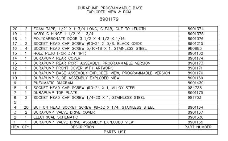
29 10 Exploded Diagram Parts List Programmable Base 28
30 29
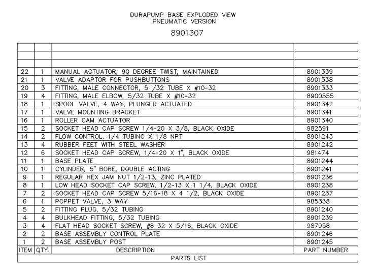
31 Durapump Base Assembly 30
32 31
33 Linear Slide Assembly 32

34 Linear Slide Assembly BOM 33
35 Valve Drive Assembly 34

36 Valve Drive Assembly BOM 35
37 36
38 11 Electrical & Pneumatic Diagrams 37
39 38
40 12 Warranty Henkel expressly warrants that all products referred to in this Instruction Manual for (Henkel DuraPump Meter Mix Dispense System) (hereafter called Products ) shall be free from defects in materials and workmanship. Liability for Henkel shall be limited, as its option, to replacing those Products which are shown to be defective in either materials or workmanship or to credit the purchaser the amount of the purchase price thereof (plus freight and insurance charges paid therefor by the user). The purchaser s sole and exclusive remedy for breach of warranty shall be such replacement or credit. A claim of defect in materials or workmanship in any Products shall be allowed only when it is submitted in writing within one month after discovery of the defect or after the time the defect should reasonably have been discovered and in any event, within (12) months after the delivery of the Products to the purchaser. This warranty does not apply to perishable items (such as seals, fuses, filters, lights, etc.). No such claim shall be allowed in respect of products which have been neglected or improperly stored, transported, handled, installed, connected, operated, used or maintained. In the event of unauthorized modification of the Products including, where products, parts or attachments for use in connection with the Products are available from Henkel, the use of products, parts or attachments which are not manufactured by Henkel, no claim shall be allowed. No Products shall be returned to Henkel for any reason without prior written approval from Henkel. Products shall be returned freight prepaid, in accordance with instructions from Henkel. NO WARRANTY IS EXTENDED TO ANY EQUIPMENT WHICH HAS BEEN ALTERED, MISUSED, NEGLECTED, OR DAMAGED BY ACCIDENT. EXCEPT FOR THE EXPRESS WARRANTY CONTAINED IN THIS SECTION, HENKEL MAKES NO WARRANTY OF ANY KIND WHATSOEVER, EXPRESS OR IMPLIED, WITH RESPECT TO THE PRODUCTS. ALL WARRANTIES OF MERCHANTABILITY, FITNESS FOR A PARTICULAR PURPOSE, AND OTHER WARRANTIES OF WHATEVER KIND (INCLUDING AGAINST PATENT OR TRADEMARK INFRINGEMENT) ARE HEREBY DISCLAIMED BY HENKEL AND WAIVED BY THE PURCHASER. THIS SECTION SETS FORTH EXCLUSIVELY ALL OF LIABILITY FOR HENKEL TO THE PURCHASER IN CONTRACT, IN TORT OR OTHERWISE IN THE EVENT OF DEFECTIVE PRODUCTS. WITHOUT LIMITATION OF THE FOREGOING, TO THE FULLEST EXTENT POSSIBLE UNDER APPLICABLE LAWS, HENKEL EXPRESSLY DISCLAIMS ANY LIABILITY WHATSOEVER FOR ANY DAMAGES INCURRED DIRECTLY OR INDIRECTLY IN CONNECTION WITH THE SALE OR USE OF, OR OTHERWISE IN CONNECTION WITH, THE PRODUCTS, INCLUDING, WITHOUT LIMITATION, LOSS OF PROFITS AND SPECIAL, INDIRECT OR CONSEQUENTIAL DAMAGES, WHETHER CAUSED BY NEGLIGENCE FROM HENKEL OR OTHERWISE. 39
41 Loctite Industrial Henkel Loctite Corporation 1001 Trout Brook Crossing Rocky Hill, CT Henkel Loctite Automtotive Technology Center 2455 Featherstone Road Auburn Hills, Michigan Henkel Loctite Corporation 2225 Meadowpine Boulevard Mississauga, Ontrario L5N 7P2 Henkel Ltda. Brazil Av. Prof. Vernon Krieble, Itapevi Sao Paulo, Brazil Henkel Capital, S.A. de C.V. Calzada de la Viga, s/n, Fracc. Los Laureles Loc. Tulpetlac, C.P Ecatepac de Morelos, Edo de Mexico, Mexico Loctite is a registered trademark of Henkel Loctite Corporation, U.S.A Copyright Henkel Loctite Corporation. All rights reserved. Data in this operation manual is subject to change without notice. Manual P/N: Rev E, 04/
EQUIPMENT Operation Manual. Loctite DuraPump Meter Mix System Part Numbers
 EQUIPMENT Operation Manual Loctite DuraPump Meter Mix System Part Numbers 1041648 1041647 1041643 1041636 1041641 1041620 1041637 1041633 Table of Contents 1 Please Observe the Following 4 1.1 Emphasized
Frekote Adjustable Spray Applicator 6 Extension Extension Extension EQUIPMENT Operation Manual
 Frekote Adjustable Spray Applicator 6 Extension 98183 12 Extension 98184 24 Extension 98185 EQUIPMENT Operation Manual 1 Please Observe The Following 1.1 Emphasized Sections Warning! Refers to safety regulations
MM10 Dual Cartridge Dispenser 1:1 & 2:1 A Style Cartridges MM10 Dual Cartridge Dispenser 1:1 & 2:1 B Style Cartridges
 EQUIPMENT Operation Manual Loctite MM10 Dual Cartridge Dispensers 1633364 MM10 Dual Cartridge Dispenser 1:1 & 2:1 A Style Cartridges 1633365 MM10 Dual Cartridge Dispenser 1:1 & 2:1 B Style Cartridges 1633366
ml Dual Cartridge Dispenser 10:1 B Style Cartridge ml Dual Cartridge Dispenser 1:1 & 2:1 B Style Cartridge
 EQUIPMENT Operation Manual Loctite 50ml Dual Cartridge Dispenser 1444133 50ml Dual Cartridge Dispenser 10:1 B Style Cartridge 1444134 50ml Dual Cartridge Dispenser 1:1 & 2:1 B Style Cartridge 1444135 50ml
Loctite Spray Valve Controller Part Number EQUIPMENT Operation Manual
 Loctite Spray Valve Controller Part Number 1406023 EQUIPMENT Operation Manual Table of Contents 1 Please Observe The Following 3 1.1 Emphasized Sections 3 1.2 For your Safety 3 1.3 Unpacking and Inspection
Loctite 300ml Cartridge Pusher Part Number EQUIPMENT Operation Manual
 Loctite 300ml Cartridge Pusher Part Number 98022 EQUIPMENT Operation Manual Table Of Contents 1 PLEASE OBSERVE THE FOLLOWING... 3 1.1 EMPHASIZED SECTIONS...3 1.2 FOR YOUR SAFETY...3 1.3 ITEMS SUPPLIED...3
Equipment Operation Manual. Loctite 250ml Bottle Hand Pump Part No Loctite 50ml Bottle Hand Pump Part No
 Equipment Operation Manual Loctite 250ml Bottle Hand Pump Part No. 97001 Loctite 50ml Bottle Hand Pump Part No. 98414 Description The Loctite 250ml Bottle Hand Pump (item # 97001) is a hand-held bottle-top
EQUIPMENT. Loctite Bench Top Air Filtration System Plenum Style Part Number Air Filtration System With Arm Part Number
 EQUIPMENT Operation Manual Loctite Bench Top Air Filtration System Plenum Style Part Number 98278 Loctite Bench Top Air Filtration System With Arm Part Number 98277 Contents Page No. 1 PLEASE OBSERVE THE
Loctite Control Timer Part Number EQUIPMENT Operation Manual. Control Timer SEC. Technologies
 I EQUIPMENT Operation Manual Warning: Electrical Hazard Disconnect Power Cord Before Removing Cover. Advertencia: Peligro eléctrico Desconecte el cable eléctrico antes de quitar la cubierta. 115 VAC, 50/60
Loctite Micro Needle Valve Part Number EQUIPMENT Operation Manual
 Loctite Micro Needle Valve Part Number 98084 EQUIPMENT Operation Manual Table of Contents 1 PLEASE OBSERVE THE FOLLOWING... 3 1.1 EMPHASIZED SECTIONS... 3 1.2 FOR YOUR SAFETY... 3 1.3 UNPACKING AND INSPECTION...
EQUIPMENT Instructions. Loctite Pneumatic 300 ml Cartridge Dispenser Part Number
 EQUIPMENT Instructions Loctite Pneumatic 300 ml Cartridge Dispenser Part Number 1294304 1. Unpacking and Inspection Carefully unpack the Loctite Pneumatic 300 ml Cartridge Dispenser and examine the items
EQUIPMENT Operation Manual. Loctite RB10 Rotary Dispense System Part Number
 EQUIPMENT Operation Manual Loctite RB10 Rotary Dispense System Part Number 1635546 1 Table of Contents 1 Please Observe The Following 3 1.1 Emphasized Sections 3 1.2 For Your Safety 1.3 Inspection 3 1.4
Loctite Spray Valve Controller Part Number EQUIPMENT Operation Manual
 Label P/N: 988341 EQUIPMENT Operation Manual FOR SPARE PARTS, MANUALS, REPAIRS, OR TECHNICAL ASSISTANCE: Visit us at equipment.loctite.com or call Henkel Corp. at: USA - (1) 860-571-5174 Germany - (49)
EQUIPMENT OPERATION MANUAL. Loctite ZETA 7401 UV Chamber
 EQUIPMENT OPERATION MANUAL Loctite ZETA 7401 UV Chamber 98039 Contents Page No. 1 Please observe the following...................................... 1 1.1 Emphasized Sections.............................................
EQUIPMENT Operation Manual. Loctite Zeta 7411 UV Flood Curing System. Part Number 98027
 EQUIPMENT Operation Manual Loctite Zeta 7411 UV Flood Curing System Part Number 98027 Table of Contents 1. PLEASE OBSERVE THE FOLLOWING... 3 1.1 EMPHASIZED SECTIONS... 3 1.2 FOR YOUR SAFETY... 3 1.3 ITEMS
EQUIPMENT Operation Manual. Loctite Zeta 7401 UV Chamber Part Number 98039
 EQUIPMENT Operation Manual Loctite Zeta 7401 UV Chamber Part Number 98039 1 Table of Contents 1 Please Observe The Following 3 1.1 Emphasized Sections 3 1.2 For Your Safety 3 1.3 Items Supplied 4 2 Description
EQUIPMENT Operation Manual
 EQUIPMENT Operation Manual Loctite Part Numbers 97115 Rotorspray Contents Page No. 1 Please Observe the Following......................................... 1-2 1.1 Emphasized Sections...................................................
EQUIPMENT Operation Manual
 EQUIPMENT Operation Manual Loctite Dispense Valve Part Numbers 97113 and 97114 Contents Page No. 1 Please Observe the Following......................................... 1-2 1.1 Emphasized Sections...................................................
EQUIPMENT Operation Manual. Loctite Advancing Slide Dispense Station. Part Number 98426
 EQUIPMENT Operation Manual Loctite Advancing Slide Dispense Station Part Number 98426 1 Table of Contents 1. PLEASE OBSERVE THE FOLLOWING... 3 1.1 EMPHASIZED SECTIONS... 3 2. DESCRIPTION... 3 2.1 OPERATION...
EQUIPMENT OPERATION MANUAL. Loctite Dial-A-Seal Dispensing System
 EQUIPMENT OPERATION MANUAL Loctite Dial-A-Seal Dispensing System 998400 Contents Page No. Please observe the following....................................... Emphasized Sections..............................................2
EQUIPMENT OPERATION MANUAL. Loctite Zeta 7740 UV Curing Wand System
 EQUIPMENT OPERATION MANUAL Loctite Zeta 7740 UV Curing Wand System 98025 Contents Page No. 1 Please observe the following...................................... 1 1.1 Emphasized Sections.............................................
UV Flood Curing System
 UV EQUIPMENT Operation Manual 7411-S ITEM # 98413 Warning: UV Energy is transmitted from this unit. Protective eyewear equipped with side shields are required that meet ANSI Z80.3 & Z87.1 Certification.
Loctite Air Filtration System Part Number EQUIPMENT. Operation Manual
 Loctite Air Filtration System Part Number 98276 EQUIPMENT Operation Manual Contents Page No. 1 PLEASE OBSERVE THE FOLLOWING................................... 1-2 1.1 EMPHASIZED SECTIONS...............................................
EQUIPMENT Operation Manual
 EQUIPMENT Operation Manual Loctite Zeta 7735 UV Curing Wand System Part Number 98317 TABLE OF CONTENTS 1. PLEASE OBSERVE THE FOLLOWING...3 1.1 EMPHASIZED SECTIONS...3 1.2 ITEMS SUPPLIED...3 1.3 FOR YOUR
EQUIPMENT Operation Manual AD988558
 EQUIPMENT Operation Manual AD988558 Loctite Pressure Rams Part Numbers 988536 Twin Post Ram, Carbon Steel, 55 Gal. 988539 Single Post Ram, Carbon Steel, 5 Gal. 988541 Twin Post Ram, Inert, 55 Gal. 988542
EQUIPMENT Operation Manual
 EQUIPMENT Operation Manual Loctite MMD Dispense Valve Manual Part Number 989027, 1:1-5:1 Abrasion Resistant 989096, 1:1-5:1 Stainless Steel 989098, 5.05:1 10:1 Stainless Steel 989099, 5.05:1 10:1 Abrasion
EQUIPMENT Operation Manual. Loctite Single Rotary Dispense Station. Part Number 98427
 EQUIPMENT Operation Manual Loctite Single Rotary Dispense Station Part Number 98427 1 Table of Contents 1. PLEASE OBSERVE THE FOLLOWING... 4 1.1 EMPHASIZED SECTIONS... 4 2. DESCRIPTION... 4 2.1 OPERATION...
EQUIPMENT Operation Manual
 EQUIPMENT Operation Manual Light Cure Valve Part Number 98009 Cyanoacrylate Adhesive Valve Part Number 98013 Contents Page No. 1 Specifications..................................................... 1 2
EQUIPMENT Operation Manual. Posi-Link Coupled Cylinder Assembly. Item No Posi-Link Controller P/N:
 Program Mode Enter Exit Select Adhesive Pkg Dose Size Input Teach Posi-Link Controller P/N: 98377 Rate Dispense Suck Back Delay Enter Engage New Package Home Unload Stop Dispense Run Mode Auto Manual Select
WORLDWIDE EQUIPMENT. Hand-held Applicator OPERATION MANUAL GLOBAL AVAILABILITY GLOBAL SERVICE
 WORLDWIDE EQUIPMENT OPERATION MANUAL Hand-held Applicator 97111 97112 97116 GLOBAL AVAILABILITY GLOBAL SERVICE HAND-HELD APPLICATOR 97111/97112/97116 AN INTEGRATION OF ADHESIVE AND EQUIPMENT TECHNOLOGY
EQUIPMENT Operation Manual
 TM EQUIPMENT Operation Manual START Panasonic TIMER POWER Single CureJet Controller Item # 1364033 TIMED MODE RESET UP CURE LIGHT ON LOCK LT4H DOWN FAULT MANUAL MODE For: LEDs Loctite Single CureJet TM
EQUIPMENT Operation Manual
 TM EQUIPMENT Operation Manual START Panasonic TIMER POWER Single CureJet Controller Item # 1364033 TIMED MODE RESET UP CURE LIGHT ON LOCK LT4H DOWN FAULT MANUAL MODE For: LEDs Loctite Single CureJet TM
Operating Manual High Viscosity Dispense Valve Item #
 Operating Manual High Viscosity Dispense Valve Item # 984594 CLOSE OPEN Item # 984594 Label # 8901197 Warnings INJECTION HAZARD Spray from the valve, hose leaks, or ruptured components can inject fluid
EQUIPMENT # OPERATION MANUAL DISPENSING SYSTEM
 EQUIPMENT OPERATION MANUAL #986000 DISPENSING SYSTEM Contents Section Description Page No. 1 Introduction...1 Items Supplied...2 View of Pump-A-Bead II with components labeled...3 2 Theory of Operation...4
Loctite 100W UV Curing Wand System Part Number EQUIPMENT Operation Manual
 Loctite 100W UV Curing Wand System Part Number 1377200 EQUIPMENT Operation Manual TABLE OF CONTENTS 1. PLEASE OBSERVE THE FOLLOWING...3 1.1 EMPHASIZED SECTIONS...3 1.2 ITEMS SUPPLIED...3 1.3 FOR YOUR SAFETY...3
EQUIPMENT Operation Manual
 EQUIPMENT Operation Manual CL15 UV Wand System Item No. 1661548 + Enter _ Warning: UV Energy is transmitted from the end of the light guide. Protective eyewear equipped with side shields are required that
EQUIPMENT Operation Manual
 EQUIPMENT Operation Manual TIMER Exposure Time LT4H Lamp On RESET LOCK N is Timed UP DOWN Lamp Hours HOURS 1 10 UV CURTIS Warning: UV Energy is transmitted from the end of the light guide. Protective eyewear
CRD610 Automatic Fitting Inserter
 CRD610 Automatic Fitting Inserter OPERATIONS MANUAL VERSION 1.2 LAST EDITED 12.12.2018 cleanroomdevices.com 1 Table of Contents Title Page. 1 Table of Contents...2 1.0 General Product & Safety Information....3
Equipment Operation Manual. CA Volumetric Hand Pump Part No
 Equipment Operation Manual CA Volumetric Hand Pump Part No. 1506477 Loading and Priming Screw bottle into Fluid Element Cap by turning bottle. Tighten with pliers Ensure that the lower Fluid Element Dispense
CLEAN ROOM DEVICES, LLC "WHERE TUBING AND FITTINGS COME TOGETHER"
 CLEAN ROOM DEVICES, LLC "WHERE TUBING AND FITTINGS COME TOGETHER" CRD600AF Automatic Fitting Inserter With Auto Feed OPERATIONS MANUAL (Shown with optional alcohol dispenser) 1 VERSION 1.1 LAST EDITED
EQUIPMENT OPERATION MANUAL. Loctite Hysol Wheel Coater
 EQUIPMENT OPERATION MANUAL Loctite Hysol Wheel Coater 98038 Contents Page No. 1 Please observe the following...................................... 1 1.1 Emphasized Sections.............................................
EQUIPMENT. Loctite Series 9000 Rotospray System OPERATION MANUAL. Pump Reservoir Head PRODUCT RESERVOIR
 EQUIPMENT OPERATION MANUAL PRODUCT RESERVOIR FULL ADD 1 LITER Loctite Series 9000 Rotospray System ADD 2 LITERS ADD 3 LITERS BEAD OF LOCTITE PRODUCT DISPENSED BY NON-CONTACT MEANS INSIDE A BORE. Pump 983330
CLEAN ROOM DEVICES, LLC "WHERE TUBING AND FITTINGS COME TOGETHER"
 CLEAN ROOM DEVICES, LLC "WHERE TUBING AND FITTINGS COME TOGETHER" CRD600 Automatic Fitting Inserter OPERATIONS MANUAL VERSION 2.1 LAST EDITED 7.25.14 DOCUMENT NUMBER 001 cleanroomdevices.com 1 Table of
CRD600 Automatic Fitting Inserter
 CRD600 Automatic Fitting Inserter OPERATIONS MANUAL VERSION 2.3 LAST EDITED 12.07.2018 cleanroomdevices.com 1 Table of Contents Title Page.. 1 Table of Contents. 2 1.0 General Product & Safety Information...3
7760A. EQUIPMENT Operation Manual. Loctite Zeta 7760A UV Curing Wand System Part Number: Exposure Time. Timed. Manual. Lamp Hours.
 EQUIPMENT Operation Manual Timed 7760A Exposure Time TIMER LT4H RESET UP Manual N LOCK is DOWN UV Warning: UV Energy is transmitted from the end of the light guide. Protective eyewear equipped with side
Operating Manual. VoluDrop Dispenser UV
 Operating Manual VoluDrop Dispenser UV 97650 Contents English...3-16 2 Contents 1 Please observe the following...4 1.1 Emphasized Sections...4 1.2 Items Supplied...4 1.3 For Your Safety...5 1.4 Field of
Adjustable Angled Incline Conveyor Owners Manual with Operating Instructions
 Adjustable Angled Incline Conveyor Owners Manual with Operating Instructions Revision 012211 Table of Contents Basic Conveyor Features 3 Getting Started 4 Setting Up the Incline Conveyor 5 Belt Removal
Active Controlled Cooling System
 Active Controlled Cooling System April 2011 3267 Progress Dr Orlando, FL 32826 www.apecor.com Preliminary www.apecor.com Table of Contents General Information... 3 Safety... 3 Introduction... 3 What s
Techcon Systems TS5000 Series Rotary Valve
 10. SPARE PARTS AND ACCESSORIES 10.1 SPARE PARTS: The only spare parts available are: Fluid inlet fitting, O- ring and clean out screw. These items are included in the Valve cleaning kit part number: 5000-013-000
New & Improved VariFlo Plural Component Equipment. Low Pressure Polymer Dispensing Equipment
 New & Improved VariFlo Plural Component Equipment Low Pressure Polymer Dispensing Equipment Table of Contents Page One Page Two Page Three Page Four Page Five Page Six Page Seven Page Eight Page Nine Page
ECLIPSE Laundry Dispenser Controller
 ECLIPSE Laundry Dispenser Controller Reference Manual Programming and Operation Online and downloadable Product Manuals and Quick Start Guides are available at www.hydrosystemsco.com Please check online
BC Brake Caliper. (i) MEX (55) QRO (442) MTY (81) DIST. AUTORIZADO
 MEX (55) QRO (442) MTY (81) DIST. AUTORIZADO") MEX (55) 5 6 QRO (44) 95 7 60 MTY () 54 0 BC Brake Caliper (i) FORM NO. L-0066-B-040 In accordance with Nexen s established policy of constant product improvement, the specifications contained in this
MEX (55) 5 6 QRO (44) 95 7 60 MTY () 54 0 BC Brake Caliper (i) FORM NO. L-0066-B-040 In accordance with Nexen s established policy of constant product improvement, the specifications contained in this
CLEAN ROOM DEVICES, LLC "WHERE TUBING AND FITTINGS COME TOGETHER"
 CLEAN ROOM DEVICES, LLC "WHERE TUBING AND FITTINGS COME TOGETHER" CRD400 Fitting Inserter OPERATIONS MANUAL VERSION 3.1 LAST EDITED 03.08.11 DOCUMENT NUMBER 001 cleanroomdevices.com 1 Table of Contents
Installation & Operation Manual. IMPORTANT: This manual contains important information. READ AND KEEP FOR REFERENCE.
 Elecronic Preset Meter 2 Industrial Handheld Series Model EPM2-IND Standard Series IMPORTANT: This manual contains important information. READ AND KEEP FOR REFERENCE. IOM-139-02-EN (1-12) 53400-139 Rev.
Techcon Systems TS7000 Series Interchangeable Material Path Rotary Valve
 Techcon Systems TS7000 Series Interchangeable Material Path Rotary Valve User Guide Copyright OK International CONTENTS Page number 1. Specifications 3 2. Unpacking and inspection 4 3. Description 4 4.
CRD400 Fitting Inserter OPERATIONS MANUAL
 CRD400 Fitting Inserter OPERATIONS MANUAL ORIGINAL INSTRUCTIONS VERSION 3.4 LAST EDITED 01.07.2019 www.cleanroomdevices.com 1 Table of Contents Title Page.. 1 Table of Contents... 2 1.0 General Product
LUBRICATOR GUN INSTRUCTIONS-PARTS LIST. 10,000 psi (700 bar) Maximum Delivery Pressure. Detachable-type
 Maximum Delivery Pressure. Detachable-type") INSTRUCTIONS-PARTS LIST 306 460 INSTRUCTIONS This manual contains important warnings and information. READ AND KEEP FOR REFERENCE. Rev. E Supercedes D Detachable-type LUBRICATOR GUN 10,000 psi (700 bar)
INSTRUCTIONS-PARTS LIST 306 460 INSTRUCTIONS This manual contains important warnings and information. READ AND KEEP FOR REFERENCE. Rev. E Supercedes D Detachable-type LUBRICATOR GUN 10,000 psi (700 bar)
Operating Instructions & Parts Manual. Supa-Lite Lever Grease Gun. Model 48UJ77
 Operating Instructions & Parts Manual EN Supa-Lite Lever Grease Gun Model 48UJ77 PLEASE READ AND SAVE THESE INSTRUCTIONS. READ CAREFULLY BEFORE ATTEMPTING TO ASSEMBLE, INSTALL, OPERATE OR MAINTAIN THE
Techcon Systems TS500R-PC Controller For Positive Displacement PC Pump
 Techcon Systems TS500R-PC Controller For Positive Displacement PC Pump Copyright OK International CONTENTS Page Number 1. Safety 3 2. Symbol Definitions.. 3 3. Specifications... 4 4. Features.. 5 5. Setup
HR-20P Pneumatically Controlled Pressure Regulator
 HR-20P Pneumatically Controlled Pressure Regulator Instruction and Service Manual Hydroplex Corporation 230 West Gloria Switch Rd. Lafayette, LA 70507 337-233-0626 www.hydroplexpumps.com I. General Instructions
Warning and Safety Precautions
 EXPRESS WARRANTY AND DISCLAIMER OF IMPLIED WARRANTIES Lily Corporation unconditionally guarantees its products to be free of defects in material or workmanship and further warrants that, for a period of
Model P-40 & Model P-25 POWER PUSHER
 Power Pusher Description INSTRUCTION MANUAL The Power Pusher provides ram capability by using the spreading power of the POWER HAWK P-16 Rescue Tool. (The Power Pusher may also be used with other spreader
OWNER/OPERATOR MANUAL. Airmotor effective dia. in. 2.5
 MODELS 282050, 282716 & 283513 AIR OPERATED CHASSIS PUMP SERIES A OWNER/OPERATOR MANUAL SPECIFICATIONS Airmotor effective dia. in. 2.5 Airinlet Material outlet 1/4 NPTF 1/4 NPTF Liquid to Air Pressure
Web Volume Control Model WV220
 WEB CONTROL PRODUCTS User Manual Web Volume Control Model WV220 1 In accordance with Nexen s established policy of constant product improvement, the specifications contained in this manual are subject
HAYWARD FLOW CONTROL TBH SERIES TRUE UNION BALL VALVE INSTALLATION, OPERATION AND MAINTENANCE INSTRUCTIONS
 HAYWARD FLOW CONTROL TBH SERIES TRUE UNION BALL VALVE INSTALLATION, OPERATION AND MAINTENANCE INSTRUCTIONS Pg. 1 of 10 PLEASE READ THE FOLLOWING INFORMATION PRIOR TO INSTALLING AND USING HAYWARD TBH SERIES
Lubricator Gun: 10,000 psi (700 bar) Maximum Delivery Pressure when disconnected from Dispenser
 Maximum Delivery Pressure when disconnected from Dispenser") INSTRUCTIONS-PARTS LIST 30 455 INSTRUCTIONS This manual contains important warnings and information. READ AND KEEP FOR REFERENCE. Rev. C Supercedes B Hand-Operated Portable Grease Dispenser Buckshot Luber
INSTRUCTIONS-PARTS LIST 30 455 INSTRUCTIONS This manual contains important warnings and information. READ AND KEEP FOR REFERENCE. Rev. C Supercedes B Hand-Operated Portable Grease Dispenser Buckshot Luber
MODEL G300 BRAKE BLEEDER
 MODEL G300 BRAKE BLEEDER Installation, Operation & Repair Parts Information Branick Industries, Inc. 4245 Main Avenue P.O. Box 1937 Fargo, North Dakota 58103 REV120716 P/N: 81-0035H THIS PAGE INTENTIONALLY
Graco PD44. Patented Meter, Mix and Dispense Valve for Two-Component Micro Dispensing
 Graco PD44 Patented Meter, Mix and Dispense Valve for Two-Component Micro Dispensing Graco PD44 Valve for Precise Micro-Dispensing 1.0cc 0.50cc 0.25cc 0.1cc 0.005cc 1/16" Dia. 1/8" Dia. 3/16" Dia. 1/4"
PENBERTHY MODELS GL AND GH GAS OPERATED JET PUMPS INSTALLATION, OPERATION AND MAINTENANCE INSTRUCTIONS
 Before installation, these instructions must be read carefully and understood. PRODUCT WARRANTY Emerson warrants its Penberthy products as designed and manufactured to be free of defects in the material
Benchmark HD Series Heavy Duty Bench Scale. Installation Manual
 Benchmark HD Series Heavy Duty Bench Scale Installation Manual 93631 Contents 1.0 Introduction... 1 1.1 Benchmark HD Specifications...................................................... 1 2.0 Installation...
Roller Door Operator
 INSTALLATION INSTRUCTIONS AND OWNERS MANUAL Roller Door Operator IMPORTANT PLEASE READ THESE INSTRUCTIONS CAREFULLY PRIOR TO COMMENCING THE INSTALLATION OF THE OPERATOR UNIT CAUTION This Automatic Opener
TBM Series 3-Way Ball Valve
 www.simtechusa.com TBM Series 3-Way Ball Valve Operating, Installation, & Maintenance Manual Corrosion Resistant Fluid and Air Handling Systems. Dated 06-26-13 TBM Series Ball Valves SIMTECHRECOMMENDSREADINGTHEFOLLOWINGINFORMATIONPRIORTOINSTALLINGANDUSING
Window Thermometer models / / 00423
 Instruction Manual Window Thermometer models 00305 / 00306 / 00423 CONTENTS Unpacking Instructions... 2 Package Contents... 2 Product Registration... 2 Features & Benefits... 3 Setup... 3 Placement Guidelines...
MITYFLEX PERISTALTIC PUMPS
 MITYFLEX PERISTALTIC PUMPS PERISTALTIC DOSING PUMP OPERATING MANUAL MODEL: 850DS Peristaltic Controlled Dosing Pump IdealSuppliesllc.com 3580 Progress Dr, Unit N Bensalem, PA 19020 844.344.6565 1 TABLE
OWNER S MANUAL WARNING
 FLUID EVACUATOR Item Number W54171 OWNER S MANUAL WARNING It is the owner and/or operators responsibility to study all WARNINGS, operating, and maintenance instructions contained on the product label and
Pro Shot Grease Dispense Valve
 Instructions Parts List Pro Shot Grease Dispense Valve 309032J For high pressure grease dispense. 8000 psi (55 MPa, 552 bar) Maximum Working Pressure Model No. 242055, Series B, 1/4 npt Fluid Inlet Model
Autosealer Hernon Manufacturing Autosealer
 Autosealer 2650 110-128 121 Tech Drive Sanford, FL 32771 www.hernon.com Phone: (407) 322-4000 Fax: (407) 321-9700 August 2015 1 P a g e About This Manual Thank you for selecting Hernon's Autosealer 2650
Model 2053 Conductivity Meter Instruction Manual
 Model 2053 Conductivity Meter Instruction Manual Printed in U.S.A. 09/2006 Ship Date: Serial Number: Calibrated By: Table of Contents Page 1. Introduction.. 1 2. Shipping Checklist.. 1 3. Specifications...
DAP-625S and DAP-875S
 AIR CHAMP PRODUCTS DAP-625S and DAP-875S (i) FORM NO. L-20078-B-0501 In accordance with Nexen s established policy of constant product improvement, the specifications contained in this manual are subject
SUNTURA HD SOLAR TRACKER
 WindyNation SUNTURA HD SOLAR TRACKER SOT-TRKS-NFHD User s Manual Page 1 of 11 WindyNation 08/09/2012 Table of Contents 1! Introduction... 3! 1.1! Limited Warranty... 3! 1.2! Restrictions... 3! 1.3! Warranty
SUNTURA SOLAR TRACKER
 WindyNation SUNTURA SOLAR TRACKER SOT-TRKS-NF User s Manual Page 1 of 10 WindyNation 08/09/2012 Table of Contents 1 Introduction... 3 1.1 Limited Warranty... 3 1.2 Restrictions... 3 1.3 Warranty Claims
PENBERTHY FROST PROOF EXTENSION INSTALLATION, OPERATION AND MAINTENANCE INSTRUCTIONS
 Before installation these instructions must be read fully and understood PRODUCT WARRANTY Emerson warrants its Penberthy products as designed and manufactured to be free of defects in the material and
Cyclone II. Cyclone. and OPERATOR S MANUAL IMPORTANT- READ OPERATOR S MANUAL BEFORE USE.
 Cyclone and Cyclone II OPERATOR S MANUAL IMPORTANT- READ OPERATOR S MANUAL BEFORE USE. 4401 Page Ave. Michigan Center, Michigan 49254 800-248-4010 www.adcocorp.com Rev. 0410 Introduction To the Cyclone
Single-Position Detent Clutch DC Series. (i) MTY (81) MEX (55) QRO (442)
 MTY (81) MEX (55) QRO (442)") Single-Position Detent Clutch DC Series (i) FORM NO. L-2017-A-001 In accordance with Nexen s established policy of constant product improvement, the specifications contained in this manual are subject
Single-Position Detent Clutch DC Series (i) FORM NO. L-2017-A-001 In accordance with Nexen s established policy of constant product improvement, the specifications contained in this manual are subject
MODEL G300 Brake Bleeder
 MODEL G300 Brake Bleeder Installation, Operation & Repair Parts Information Branick Industries, Inc. 4245 Main Avenue P.O. Box 1937 Fargo, North Dakota 58103 Rev013107 P/N: 81-0035C CAUTION Before using
HYDRAULIC POWER PACK
 HYDRAULIC POWER PACK OPERATION & MAINTENANCE MANUAL Model 34484 Copyright 2012 by All rights reserved. No part of this publication may be copied, reproduced or transmitted in any form whatsoever without
Agxcel GX12i Chemical Injection System
 Agxcel GX12i Chemical Injection System Table of Contents System Contents... 3 Specifications... 4 Safety Precautions and Tips... 5 Operations... 6 Installation... 7 Maintenance... 8-9 Troubleshooting...
UV PROCESS SUPPLY, INC. CON-TROL-CURE ½ DIAPHRAGM PUMP INSTRUCTION MANUAL PART # J
 1 IMPORTANT: READ THIS MANUAL CAREFULLY BEFORE INSTALLING, OPERATING OR SERVICING. PUMP DATA TYPE: MAT'L: WEIGHT: Air Operated Double Diaphragm Polypropylene or PVDF or Acetal PVDF (Polyvinylidene Fluoride)
Parts Manual. Spray Gun Series Master II. Issue /09/2017 Ref. NR ENG
 Spray Gun Series Master II Issue 3.2 27/09/2017 Ref. NR-00020-ENG Before starting or carrying out maintenance work on the MASTER II gun, please carefully read all the technical and safety documentation
INSTRUCTIONS PARTS LIST This manual contains important warnings and information. READ AND RETAIN FOR REFERENCE
 INSTRUCTIONS PARTS LIST 308 493 This manual contains important warnings and information. READ AND RETAIN FOR REFERENCE Rev. A Second Gun Hose Kit 100 psi (6.9 bar) Maximum Working Pressure These kits include
D Instructions/Parts. Siphon Feed Detail Spray Gun D
 Instructions/Parts D-5-55 Siphon Feed Detail Spray Gun FOR PRODUCT INFORMATION CALL: 1-800-742-7731 309991D Important Safety Instructions Read all warnings and instructions in this manual. Save these instructions.
GC-1. Roof and Gutter De-Icing Control Installation and Operating Instructions FOR EXTERIOR INSTALLATION ONLY
 GC-1 Roof and Gutter De-Icing Control Installation and Operating Instructions FOR EXTERIOR INSTALLATION ONLY GENERAL INFORMATION The GC-1 heating cable controller has been designed and manufactured for
MGFHVLP. Instructions/Parts. Mini Gravity Feed System E. Part No Includes MGFHVLP Mini Gravity Feed Spray Gun and MGC 125 Gravity Cup.
 Instructions/Parts MGFHVLP Mini Gravity Feed System FOR PRODUCT INFORMATION CALL: 1-800-742-7731 309989E For gravity feed spraying of automotive colors and clears. Ideal for touch-up and detail work. Important
PARTS LIST. Guardian VR-Series. Material Pumps
 PARTS LIST Guardian VR-Series Material Pumps Table Of Contents Section 1 General Information 1:0 Technical Information... 1 1:1 Assembly Drawings... 5 1:2 Sub Assembly Drawings... 16 1:3 Maintenance...
Techcon Systems TS5000DMP Series Disposable Material Path Rotary Auger Valve. User Guide
 Techcon Systems TS5000DMP Series Disposable Material Path Rotary Auger Valve User Guide CONTENTS Page number 1. Specifications 3 2. Unpacking and Inspection.4 3. Description........4 4. Theory of Operation..
P5510. Users Manual. Pneumatic Comparison Test Pump
 P5510 Pneumatic Comparison Test Pump Users Manual PN 3952297 November 2010 2010 Fluke Corporation. All rights reserved. Printed in USA. Specifications are subject to change without notice. All product
Premium Series Grease Dispensing Handle One and Two Piece Body Styles
 Service Bulletin SB3018 Rev. A 3/07 Premium Series Grease Dispensing Handle One and Two Piece Body Styles Models: Handle w/swivel and 36" Whip Hose 020 Handle w/swivel and 18" Whip Hose 025 Handle w/swivel
Single Pump Station with Delay, 10HP/1PH DU PS2001C-PG
 Single Pump Station with Delay, 10HP/1PH DU PS2001C-PG Owner s Manual #0810 Customer Number: Model Number: Serial Number: Installation Date: Please read and u n d e r s t a n d t h i s manual. Store in
AIR VELOCITY METER ALNOR MODEL AVM410 AIRFLOW INSTRUMENTS MODEL TA410
 AIR VELOCITY METER ALNOR MODEL AVM410 AIRFLOW INSTRUMENTS MODEL TA410 OPERATION AND SERVICE MANUAL P/N 1980575, REV F FEBRUARY 2016 Copyright TSI Incorporated / 2007-2016 / All rights reserved. Address
ITA / ITB - AS / AP / AP SERIES Electronic Table Top Weighing Balance
 TM ITA / ITB - AS / AP / AP SERIES Electronic Table Top Weighing Balance Scale Users Guide ISHTAA SCALES INC., INDIA www.ishtaascales.com 14 Content 1. Technical Data... 1 2. Installation... 2 3. Controls