MANUAL. Servicebox 817
|
|
|
- Julian Owens
- 5 years ago
- Views:
Transcription

1 MANUAL Servicebox 817
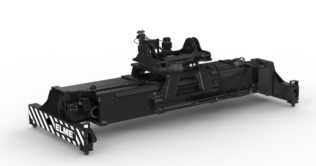
2 Thank you for purchasing this Servicebox to your 817! This guide provides the information needed to service and maintain your spreader at 5,000 hour service. A spreader used and serviced properly retain their qualities for a long and profitable life in service, and you get the full advantage of all the features. Maintenance may only be carried out by qualified personnel. For more detailed information about spare parts and service instructions, we refer to our manual for the specific spreader. All information, illustrations and specifications in this manual are based on the latest information at the time of publication. The right is reserved to make changes at any time without notice. COPYRIGHT 2015 ELME Spreader AB.
3 Index Twistlock Assembly 4-9 Wear pads Flextrack Chain Assembly Additional Parts Summary of all parts included 18 Why use Genuine Parts? 19

4 TWISTLOCK ASSEMBLY The twistlock is a genuine ELME part, which is certified and marked with a unique serial number.
 in the top of both twistlocks in the same end beam.")
5 The tie-rod is a fixed unit and is not adjustable. 1 To remove the tie-rod proceed as follows: 1 Remove the Locked / Not locked sensor bracket (item 1). 2 Loosen one of the adjuster bolts at the twistlock cylinder, enough to give some play. 3 Loosen and remove the M8 x 80 bolts (item 2) in the top of both twistlocks in the same end beam. 4 Use two of the M8 x 80 bolts (item 2) as pullers by inserting them in the two threaded holes (item 3) in each of the cranks (item 4) and tighten them alternately until they lift the cranks (item 4) off the top of the twistlock shaft (item 5). 5 The tie-rod (item 6) including both cranks (item 4) can now be removed from the endbeam. Now, it is also possible to replace the O-ring, washer and ball joint (item 14). To remove the twistlock and sleeve proceed as follows: 6 The key (item 7) that locates the crank (item 4) to the twistlock (item 5) is held in place on the twistlock by a roll pin, so that it will remain in place on the twistlock after the crank is removed. By lightly knocking the key away from the twistlock, it can be removed. 5
6 7 Support the twistlock (item 5) from below so that it does not drop out. Using a screwdriver prise the collets (item 8) out of the recess in the twistlock (item5). It is now possible to lower the twistlock out of the end beam. The sleeve (item 9) and lower bearing set (item 10) will in most cases accompany the twistlock as it is removed. This is quite normal. Inspection prior to reassembly 8 After removal of all twistlock parts, remove all grease and dirt from the parts and also from the corner of the end beam. Steam clean or clean with some form of solvent. 9 Heck the twistlock (item 5) for wear at the head and also for wear at the bushing surfaces. Inspect the lower (item 10) and upper (item 11) bearing sets for wear and damage. If badly worn or damaged, they should be replaced. The collets (item 8) and and the crank (item 4) should be inspected for possible wear or damage and replaced if necessary. It should be noted that the state of the collets (item 8) and the recess in the twistlock (item 5) is very important, as these parts are carrying the load when a container is lifted. Replacing / Fitting twistlocks 10 Prepare the sleeve (item 9), place and grease the bushing and fit the four centering springs in the sides of the sleeve. 11 Grease the upper bearing set (item 11) and place in position on the greased top surface of the corner plate (in the endbeam) with the convex half uppermost (threaded holes up). Grease the lower bearing set (item 10) and place in position on the greased bottom surface of the corner plate (in the endbeam, the grease will hold it in place). 12 Lift the sleeve assembly as assembled in point 10 and position up through the corner plate in the endbeam. Note the direction of the grease nipple! Then place the twistlock in the sleeve, ensuring that both bearings (item 10 and 11) are positioned correctly around the twistlock. Support the assembly with a jack or other means. 13 Fit the collets (item 8) with the pointed part upwards. 14 Fit the key (item 7) incl. roll pin to the keyway of the twistlock (item 5). 6
7 15 In order to fit the tie-rod (item 6), it is necessary to mount both cranks (item 4) to the tie-rod before placing it in the end beam. Fit the ball joints, O rings, and plastic washers to the tie-rod ends and then fit the fork of the crank (item 4) over the tierod end. Ensure that the countersunk ends of the securing holes in the crank are upper most. Secure the crank to the tie-rod end by fitting the pin (item 12) and then the ring pin and allen screw (item 13). 16 In order to simplify assembly of the crank to the twistlock, it is advisable to fit two alignment pins to the assemby. The pins can be made from two M8 x 75 bolts or allen screws with the heads removed and slightly chamfered. These pins should be screwed into the top plate of the upper bearing (item 11) diagonally so that each pin guides one half of the collets (item 8). 17 Insert the tie-rod (item 6) into the end beam and then fit the cranks (item 4) onto the alignment pins and ensure that the key and keyway line up. Fit two of the allens securing (item 2) in the remaining two holes and screw in and tighten lightly. Remove the alignment pins and fit the other two securing screws. The securing screws can now be tightened to approx. 25 Nm. 18 Activate the twistlocks to the NOT LOCKED position and then adjust the twistlock cylinder adjuster bolts, so that the twistlocks are positioned accurately in the NOT LOCKED position. Then adjust properly, see Twistlock angle adjustment. 19 Grease the complete assembly with a high-pressure grease gun. In order to test the operation, it is necessary to land the spreader on a container so that the seated pins are activated. 7
8 Proximity switch / Sensor Proximity switch / Sensor bracket 7 to 8mm Mounting surface 8-10 mm Distance from landing surface to underside of seated pin Seated pin Landing surface of end beam Seated / Landed signal adjustment 1 Check that the SEATED PIN can move up and down freely. The force needed to lift the pin is approx. 10 kg (20 lbs). 2 The SEATED signal should switch on with the pin protruding approx. 9 mm below the landing surface of the end beam. 3 If adjustment of the proximity switch / sensor is necessary, remove the seated sensor mounting bracket incl. sensor from the top of the seated tower, and adjust the proximity switch / sensor so that the end surface is 7-8 mm above the lower mounting surface of the bracket. This adjustment will result in the seated pin indication being switched on when the underside of the seated pin is approx. 8 to 10 mm lower than the end beams landing surface. This adjustment also ensures that the mechanical and electrical lockout is released, so that the twistlocks can be turned. 8
9 6 5a 2a b 5b 1 Twistlock angle adjustment 1 Turn the twistlocks (pos 1) to the fully UNLOCKED position (as shown). 2 If the twistlock heads do not line up with the twistlock sleeve, they can be adjusted by loosening the lock nuts (pos 5) for the adjuster bolts (pos 2). 3 Turn the twistlocks at each end of the end beam, so that they line up with the sleeves. If it is found difficult to line up the twistlocks and sleeves accurately distribute the misalignment equally on both sides of the sleeve. Make sure that the twistlock heads DO NOT protrude outside the the theoretical line between twistlocks. If the twistlocks do protrude outside the previously mentioned line between the twistlocks, it can cause jamming in corner castings as the spreader is lifted off the container. 4 Run both adjuster bolts (pos 2) up to the piston rod (pos 4) ends of the twistlock cylinder (pos 3) by hand, making sure that neither the twistlocks nor the cylinder are moved. Tighten the lock nut (pos 5a) of the inside adjuster (pos 2a) first. 5 Unscrew / back off the outer adjuster bolt (pos 2b) no more than 2 flats of the hexagan head (60 ), so that there is only just enough play to allow the tie rod (pos 6) to slide back and forth across the adjuster bolts when the twistlock cylinder (pos 3) is activated. CAUTION! If the gap between the twistlock cylinder rod ends is too large, the rod ends will hammer against the adjusters and subsequent damage will occur to the piston rod ends. 6 Tighten the lock nut (pos 5b) securely while at the same time ensuring that the adjuster bolt (pos 2b) does not move. 7. Activate the twistlocks to the LOCKED position and check that the twistlock heads are / to the twistlock sleeve. 9
10 WEAR PADS To eliminate mechanical friction, there are plastic pads between extension beams and main frame. The pads are positioned for support to reduce and also to absorb horizontal and vertical shock loads, they are mounted in several retainers. This design makes inspection and replacement easy. There are also plastic pads underneath the extension cylinders and between rotator and main frame, see next page.
11 The nylon wear pads should be inspected for wear at the same time as their tracks are lubricated. Replacing the wear pads can be done with ordinary hand tools and without removing the beams. Minimum 18 mm The pads should be replaced when their thickness is reduced to minimum 18 mm. 11

12 FLEXTRACK CHAIN ASSEMBLY Included in this service box is a complete assembly of flextrack chain, hydraulic hoses and electrical cable. On the following pages, you will find instructions how to replace the flextrack chain assembly.
13 Remove the extension cylinder (item 1) and old flextrack chain (item 2) from the endbeam and dismount hoses (item 3) and cable (not shown on the picture below). Replace with new flextrack chain assembly according to below instructions Fasten the flextrack chain with bolts (M8x20 + locking nut) onto the flextrack bracket (item 4), which is moulded on the shell. Strap the flextrack chain provisionally to the valve assembly (item 5). Remove the strap, when the cylinder is mounted in the extension beam. Pull the cable (not shown on picture above) and the hoses (item 3) through the flextrack chain. Please note! Mark one of the hoses, to avoid mix-up! The male on the cable should come out where the valve assembly is. Place the cylinder (item 1), so that it rests on the flextrack chain. Turn up and pull the hoses (item 3) towards the valve assembly and fasten them with hose clamps (item 6). Remount the extension cylinder into the endbeam. 13
14 ADDITIONAL PARTS Proximity switch For replacement of old proximity switch / sensor in twistlock assembly. Seal kits For replacement of old seal kits in extension, sideshift and twistlock cylinders. See instructions on following pages.
15 Seal replacement - Sideshift cylinder Remove the side shift cylinder or tie up the cylinder when working on the spreader. Loosen gland (item 3) and hydraulic hoses and pull out the piston rod (item 1). Be careful not to damage the piston rod when removing and beware of the oil spill. Use a drift punch to remove the roll pin (item 6) and remove the nut (item 5), the piston (item 4) and the gland (item 3) from the piston rod. Check the piston rod and cylinder for damages that can cause leakage and repair or replace when necessary. Carefully remove the seals (items 2), do not damage the surfaces. Clean all parts. Place the new seals with oil or grease. Place the gland and the piston on the piston rod, tighten the nut and secure it with the roll pin. Slide the piston rod assy. into the cylinder and tighten the gland. 15
16 Seal replacement - Extension cylinder Remove the extension cylinder. Remove the 140 Bar relief valve from the side of the extension cylinder valve. (Wrench 7/8 ). Remove the bolts (item 12), and place the ring (item 10) on the painted front side of the piston rod, so that it cannot damage the surface of the rod. Pull out the piston rod, beware of the oil spill (place the hydraulic hose from the front end in a oil bin) and be carefull not to damage the piston rod. Use a drift punch to remove the roll pin (item 2) and remove the nut (item 3), the piston (item 4), the spacer (item 5), the gland (item 7) and the washer (item 9). Check the piston rod and cylinder for damages that can cause leakage and repair or replace when necessary. Carefully remove the seals (items 1). Do not damage the surfaces. Check the bushing (item 6) and the guide ring (item 8) and replace if necessary. Clean all parts. Place the new seals with oil or grease. Place the washer, gland, spacer and piston on the piston rod, tighten the nut and secure it with the roll pin. Slide the piston rod assembly into the cylinder, place the ring (item 10) and tighten the bolts evenly (78 Nm). Place the 140 Bar relief valve and tighten it. (45 Nm). 16
17 Seal replacement - Twistlock cylinder Before disassembly, check the piston rod ends. Repair/grind if they are damaged. Remove the allen screws (item 2 and 12). Remove the washers (item 4) and the plates (item 6) and pull out the piston rod (item 1). Use a drift punch to remove the roll pin from the piston (item 11) and remove the piston from the rod. Carefully remove the seals (items 3, 5, 7, 9 and 10), do not damage the surfaces. Clean all parts. Check the piston rod and cylinder for damages that can cause leakage and repair or replace when necessary. Place the new seals with oil or grease. Slide the piston on the piston rod so that the securing holes line up and place the roll pin. Slide the piston rod in the cylinder, place the plates (item 6) and tighten the M8x160 mm bolts (23 Nm). Place the plates (item 4) and tighten the bolts (23 Nm). 17
18 Summary of all parts included in the box: Twistlock Assembly 4x Twistlock kit 8x Seal ring 8x O-ring 4x Ball joint 4x Seated pin 4x Nut 4x Indicator arm 4x Compression spring 4x Compression spring 4x Tie rod Wear pads 20x Wear pad - Mainframe/ Extension beam 4x Wear pad - Mainframe 4x Wear pad - Extension cylinder 8x Wear pad - Carriage Flextrack Chain Assembly 2x Flex track chain 4x Bracket 16x Screw 4x Hydraulic hose assy. 2x Cable assy. Additional Items 4x Proximity switch 1x Seal kit - Sideshift cylinder 1x Seal kit - Extension cylinder 1x Seal kit - Twistlock cylinder 18
19 Why use Genuine Parts? ELME GENUINE PARTS By using ELME genuine parts, you always get parts you can rely on and true peace of mind. If you are using non-genuine parts, you put weak links into a strong, perfectly designed chain of interactive components. Please note that non-genuine parts are made by factories that have not been approved by ELME and they are often manufactured to be as cheap as possible, using inferior materials, workmanship and by reversed engineering. Non-genuine parts are high risk. Real cost and real risk is measured not in the price, but in the cost of the component in the event of failure. Use of non-genuine parts may lead to higher downtime and lower productivity due to more frequent failures. For correct operation of the spreader, only ELME Genuine Parts and accessories which are approved by ELME should be used. If non-genuine parts are used, the warranty is not valid. By using ELME Genuine Parts and accessories approved by ELME, you will maintain original standard. ELME will disclaim all responsibility if parts from third party are used. INSPECTION/MAINTENANCE Always inspect your spreader before using it. If any kind of damage is detected which may affect the function of the spreader - this must be corrected before use. If the spreader needs to be repaired, please contact a specialist and see to that only ELME Genuine Parts are used if need of replacement. This is to ensure that the spreader still is reliable. Repairs made by a non-qualified person or use of non-genuine parts may lead to increased risk of personal injuries or damages. Service and maintenance are necessary to keep capacity and efficiency of the spreader for many years. MODIFICATION OF THE SPREADER/PRODUCT LIABILITY/WARRANTY For the avoidance of doubt, ELME is not liable in case of damage due to factors beyond ELME s control or due to a lack of maintenance or the use of non-genuine parts. The spreader should not be modified without consultation with ELME. If so, this means that the spreader is not CE approved and thus ELME has no product liability. 19
20 HEADOFFICE ELME Spreader AB Älmhult, Sweden SALES AND SPARE PARTS ELME Spreader Trading (Shanghai) Co. Ltd Shanghai, China SPARE PARTS ELME Americas Inc. Martin, TN, United States ELME Spreader AB 2015
Pneumatic Axial Die Grinder also for Underwater Use Type , 0050
 M a s c h i n e n f a b r i k G m b H Pneumatic Axial Die Grinder also for Underwater Use Type 1 5077 0010 0020, 0050 Illustration can differ from the original Repair Manual and Compiled: 18.07.11 150770010_0020_0050_Inst_en_Version_00
1988 Chevrolet Pickup V SUSPENSION - FRONT (4WD)' 'Front Suspension - "V" Series 1988 SUSPENSION - FRONT (4WD) Front Suspension - "V" Series
' 'Front Suspension - V Series 1988 SUSPENSION - FRONT (4WD) Front Suspension - V Series") 1988 SUSPENSION - FRONT (4WD) Front Suspension - "V" Series DESCRIPTION NOTE: Vehicle serial numbers used in this article has been abbreviated for common reference to Chevrolet and GMC models. Chevrolet
1988 SUSPENSION - FRONT (4WD) Front Suspension - "V" Series DESCRIPTION NOTE: Vehicle serial numbers used in this article has been abbreviated for common reference to Chevrolet and GMC models. Chevrolet
I & M Mark 78 Series. Ideal Installation. Start-Up. Installation & Maintenance Instructions for Mark 78 Control Valves (1-1/2-2 )
") I & M Mark 8 Series 0 Wasson Road Cincinnati, OH 4509 USA Phone 5-5-5600 Fax 5-8-005 info@richardsind.com www.jordanvalve.com Installation & Maintenance Instructions for Mark 8 Control Valves (-/ - ) Warning:
I & M Mark 8 Series 0 Wasson Road Cincinnati, OH 4509 USA Phone 5-5-5600 Fax 5-8-005 info@richardsind.com www.jordanvalve.com Installation & Maintenance Instructions for Mark 8 Control Valves (-/ - ) Warning:
ORIGA SYSTEM PLUS Guides, Brakes and Valves for Modular Linear Drive Systems OSP Appendix to the Operating Instructions
 ORIGA SYSTEM PLUS Guides, Brakes and Valves for Modular Linear Drive Systems OSP Appendix to the Operating Instructions TAll personnel who have anything to do with the OSP fitted with guides, brakes or
I & M Mark 78 Series. Ideal Installation. Start-Up. Installation & Maintenance Instructions for Mark 78 Control Valves (1/2-1 )
") I & M Mark 8 Series 30 Wasson Road Cincinnati, OH 4509 USA Phone 53-533-5600 Fax 53-8-005 info@richardsind.com www.jordanvalve.com Installation & Maintenance Instructions for Mark 8 Control Valves (/ -
I & M Mark 8 Series 30 Wasson Road Cincinnati, OH 4509 USA Phone 53-533-5600 Fax 53-8-005 info@richardsind.com www.jordanvalve.com Installation & Maintenance Instructions for Mark 8 Control Valves (/ -
INSTALLATION INSTRUCTIONS ASSEMBLY & DISASSEMBLY
 8405/6ASERIES PTO INSTALLATION INSTRUCTIONS ASSEMBLY & DISASSEMBLY 8405/6A DISASSEMBLY-REASSEMBLY INSTRUCTIONS This document contains the information to properly disassemble/reassembleyour 8405/6A Series
Safety - Installation and Operation:
 4x4 or 4x2 Instructions EZGO Electric Cars Thank you for purchasing your 4x4 or 4x2 conversion kit. Safety at all times whether during installation or operation is utmost importance. Before After!!!!!!!!!!!!!!
Spicer Axles & Brakes
 Information Bulletin Bulletin Type: Parts / Service Information Spicer Axles & Brakes Topic: Dana Corporation Steer Knuckle Recall Identification and Repair Procedure Affected Models: Steer Axle Knuckle
DYNAFLUID 2000 STEAM & WATER MIXING VALVE INSTALLATION & OPERATING MANUAL
 DYNAFLUID 2000 STEAM & WATER MIXING VALVE INSTALLATION & OPERATING MANUAL LILLY ENGINEERING COMPANY 217 CATALPA STREET P.O. BOX 173 ITASCA, ILLINOIS 60143 630-773-2222 FAX: 630-773-3443 www.lillyengineering.com
INSTALLATION INSTRUCTIONS
 INSTALLATION INSTRUCTIONS --1075 North Ave. Sanger, CA 93657-3539 local: 559-875-0222 fax: 559-876-2259 toll free: 800-445-3767-- 2505 Lowering Spindle Assembly Installation Instructions ½ TON SILVERADO
Work shop manual. Öhlins Steering damper Road & Track
 Work shop manual Öhlins Steering damper Road & Track Including: Introduction Safety instructions Dismantling the steering damper Assembling the steering damper Filling oil Introduction All of Öhlins advanced
Drive unit. Installing/removing ebike components. Tool: Allen key size 8. ISIS crank-puller. Spider-Tool. Lever (e.g.
 Removing the chain wheel Remove the crank arms (Allen key size 8, ISIS crank-puller). Block the rear wheel. Tip: Clamp the brake lever with Velcro. Unscrew the lock ring () with the Spider-Tool (). Caution:
FRONT SUSPENSION LOCATION INDEX
 1. Remove the front suspension tower bar. (See FRONT SUSPENSION TOWER BAR REMOVAL/INSTALLATION.) 2007 Mazda MX-5 Miata Sport 2007 SUSPENSION Front Suspension - MX-5 Miata FRONT SUSPENSION LOCATION INDEX
INSTRUCTION MANUAL ALL TERRAIN PALLET TRUCK HAND PALLET TRUCK
 INSTRUCTION MANUAL ALL TERRAIN PALLET TRUCK HAND PALLET TRUCK WARNING! 1. Read and understand instruction manual before using the pallet truck. 2. Do not place hands or feet under the pallet truck at any
Service Handbook HD /97
 Service Handbook HD 1050 5.905-032 07/97 Foreword HD 1050 Foreword Indispensable prerequisites for the competent execution of service procedures are comprehensive, real-life training workshops for technical
POWER STEERING PUMP REBUILDING SPK101 Read instructions completely before removal & disassembly
 POWER STEERING PUMP REBUILDING SPK101 Read instructions completely before removal & disassembly DISASSEMBLY: 1. Remove pump from car and allow to drain. 2. Remove pulley from front of pump. This requires
Single-Position Detent Clutch DC Series. (i) MTY (81) MEX (55) QRO (442)
 MTY (81) MEX (55) QRO (442)") Single-Position Detent Clutch DC Series (i) FORM NO. L-2017-A-001 In accordance with Nexen s established policy of constant product improvement, the specifications contained in this manual are subject
Single-Position Detent Clutch DC Series (i) FORM NO. L-2017-A-001 In accordance with Nexen s established policy of constant product improvement, the specifications contained in this manual are subject
Safety Precautions Certain service procedures may require the vehicle/machine to be disabled (wheels raised off ground, work function disconnected, et
 Service Manual ASM 3 1 -F11 F11-5 through -250 Catalog 9129 8205-02 Februari 2001, GB Safety Precautions Certain service procedures may require the vehicle/machine to be disabled (wheels raised off ground,
Transmission Overhaul Procedures-Bench Service
 How to Assemble the Lower Reverse Idler Gear Assembly Special Instructions In 1996 Eaton changed the reverse idler system design. In the nut design, the reverse idler bearing was lubricated through a hole
Model MC-35 Impact Press. Operation & Maintenance Instructions
 Model MC-35 Impact Press Operation & Maintenance Instructions Revised 12/05/2007 WARNINGS 1. Safety glasses must always be worn by the machine operator, as well as any co-workers, or any other persons
Steering Damper MX SD 2.1. Workshop Manual
 Steering Damper MX SD 2.1 Workshop Manual Safety Precautions Before you begin Warning! Öhlins Racing AB can not be held responsible for any damage to the Steering Damper, vehicle, other property or injury
BPW height-adjustable drawbars
 Maintenance instructions ZAV BPW BERGISCHE ACHSEN BPW height-adjustable drawbars Series ZAV REPAIR, MAINTENANCE AND OPERATING INSTRUCTIONS Maintenance and Operating Instructions ZAV Table of contents:
Installation Notes: #86000-R Race Series +3.5 L/T Kit
 159 North Maple St. Unit J, CORONA CA 92880 P. 951-737-9682 F. 951-737-9006 WWW.CHAOSFAB.COM Installation Notes: #86000-R Race Series +3.5 L/T Kit Factory manual is recommended for removal and re-installation
SERVICE MANUAL. Hydraulic Motors type MM
 SERVICE MANUAL Hydraulic Motors type MM and MLHM 2008 Сервизно ръководство Демонтаж Хидравлични мотори Тип GW - 2/6 - Service Manual Disassembly Hydraulic Motor type MM, MLHM Instructions in this manual
Installation Manual TWM Performance Short Shifter Cobalt SS/SC, SS/TC, HHR SS, Ion Redline and Saab 9-3
 Page 1 Installation Manual TWM Performance Short Shifter Cobalt SS/SC, SS/TC, HHR SS, Ion Redline and Saab 9-3 Please Note: It is preferable to park on a flat surface, as you will have to engage and disengage
Marzocchi Suspension MZ III MZ III. Technical instructions
 Technical instructions Exploded view - MZ III - 100 Rif. Code Quantity Spare part list - MZ III - 100 Rif. Code Description Q.ty in the model Technical characteristics: Technical characteristics Single-crown
SUSPENSION - FRONT Infiniti G20 DESCRIPTION ADJUSTMENTS & INSPECTION SUSPENSION Front G20
 SUSPENSION - FRONT 1992 Infiniti G20 1991-92 SUSPENSION Front G20 DESCRIPTION G20 uses a 4-wheel independent multi-link suspension system. Transverse links are connected to bottom of steering knuckle.
DRIVE AXLE Volvo 960 DESCRIPTION & OPERATION AXLE IDENTIFICATION DRIVE AXLES Volvo Differentials & Axle Shafts
 DRIVE AXLE 1994 Volvo 960 1994 DRIVE AXLES Volvo Differentials & Axle Shafts 960 DESCRIPTION & OPERATION All 960 station wagon models use type 1041 rear axle assembly. All 960 4-door models use type 1045
Guides, Brakes and Valves
 Guides, Brakes and Valves Operating Instructions ORIGA SYSTEM PLUS Appendix to the Operating Instructions OSP-P / OSP-E Guides, Brakes and Valves OSP-P / OSP-E Content 1 Foreword to the Operating Instructions
Model MC-21 Impact Press. Operation & Maintenance Instructions. Revised 9/20/07
 Model MC-21 Impact Press Operation & Maintenance Instructions Revised 9/20/07 1 WARNINGS 1. Safety glasses must always be worn by the machine operator, as well as any co-workers, or any other persons in
E31 Repair Procedure Replace Front Wheel Hub/Bearing Assembly
 E31 Repair Procedure 31-21 Replace Front Wheel Hub/Bearing Assembly Disclaimer This repair procedure is provided as is and is not authoritative with respect to any BMW repair operation. Mark F. Fling is
SERVICE MANUAL US. Permobil M300/M400. Power Wheelchair
 SERVICE MANUAL US Permobil M300/M400 Power Wheelchair How to contact Permobil Head Office of the Permobil group Produced and published by Permobil AB, Sweden Version 2, 2011-06 Article no.: 205261-US-0
Rekluse Motor Sports. The z-start Clutch CRF 250X. Installation Guide Copyright 2002 Rekluse Motor Sports z-start Revision RMS116 CRF 250X
 Rekluse Motor Sports The z-start Clutch CRF 250X Installation Guide Copyright 2002 Rekluse Motor Sports z-start Revision 3.000 RMS116 CRF 250X 191-216 Manual Revision: 103105 Rekluse Motor Sports, inc.
Service Handbook High-Pressure Washer Pump
 Service Handbook High-Pressure Washer Pump 9.120-014.0 2 A. Water Inlet Filter C. Nozzle Insert 1. Remove filter with a screwdriver. 2. Clean filter with warm water and mild soap. 3. Reinstall filter.
Husqvarna Hedgetrimmers 325HS/ 325HE/ 325HDA. Workshop manual
 Husqvarna Hedgetrimmers 325HS/ 325HE/ 325HDA Workshop manual 101 90 73-26 2 Workshop Manual Hedge trimmers Supplement for models 325HS, 325HE,325HDA Contents 1. Starter 5 2. Ignition system 7 3. Fuel system
Installation Manual TWM Performance Short throw shifter 2001 and up Hyundai Accent
 Installation Manual TWM Performance Short throw shifter 2001 and up Hyundai Accent 1. Place the vehicle on a flat surface with blocks in front and behind the wheels preventing unwanted movement. The car
Rekluse Motor Sports. The z-start Clutch CRF 250R. Installation Guide Copyright 2002 Rekluse Motor Sports z-start Revision RMS112 CRF 250R
 Rekluse Motor Sports The z-start Clutch CRF 250R Installation Guide Copyright 2002 Rekluse Motor Sports z-start Revision 3.000 RMS112 CRF 250R 191-212 Manual Revision: 091205 Rekluse Motor Sports, Inc.
Service manual. English. F5 Corpus
 Service manual English F5 Corpus Introduction The Service Manual is intended for technical personnel who maintain and repair power wheelchairs. It is important that anyone who performs maintenance and
Installation Instructions COMPETITION/PLUS SHIFTER Ford Mustang MT82 6-Speed Manual Transmission Catalog#
 Installation Instructions COMPETITION/PLUS SHIFTER 2015-2017 Ford Mustang MT82 6-Speed Manual Transmission Catalog# 3916037 Rev. 00 WORK SAFELY! For maximum safety, perform this installation on a clean,
Repair Manual and Spare Parts List
 Pneumatic Drive Unit Type Techn. Doc. No. 352 and Accessories for Pipe Cutting Machine Darstellung kann vom Original abweichen Repair Manual and 580027000_Inst_en_Version_02 Repair General In general,
DP5 Pump. 5:1, Air-operated, Heavy Duty, Oil. General. Operation. Technical Data. Installation R1 09/10
 DP5 Pump 5:1, Air-operated, Heavy Duty, Oil General The DP5 Pump is a compressed air-operated reciprocating piston medium pressure pump. These pumps are suitable for distribution of all types of light
1993 SUSPENSION Volkswagen Rear. EuroVan
 Article Text ARTICLE BEGINNING 1993 SUSPENSION Volkswagen Rear EuroVan DESCRIPTION Suspension uses control arms and axle beam for stabilization. Control arms and axle beam are combined as one unit. Brake
1990 SUSPENSION Front ES250, LS400
 SUSPENSION - FRONT Article Text 1990 Lexus LS 400 For Lextreme Copyright 1998 Mitchell Repair Information Company, LLC Thursday, January 29, 2004 04:56PM ARTICLE BEGINNING 1990 SUSPENSION Front ES250,
Recommended Scheduled Maintenance
 005-08-9 () Illustrerad stol Be-Ge 900 Recommended Scheduled Maintenance Daily Inspection: Inspections every,000 working hours: Inspect and perform, if necessary, the required maintenance according to
FOR SIT-STAND WORKSTATION
 INSTALLATION MANUAL FOR SIT-STAND WORKSTATION Weight Capacity: 6.5-24.5 lbs. 6017180 Rev. B Contents Tools Required / Supplied Part Kits / Warnings/Disclaimers...2 Base Installation Clamp Mount Base Location...3
 DRUM BRAKE RIMS Periodic inspection of drum brake rims is necessary to determine indications of uneven or excessive wear. In general, brake rim failures other that regular wear are caused by brake linings
 Page 1 of 15 Transmission, Model S5-42 ZF Model S5-42 ZF Disassembly NOTE: For 4x4 and F-Super Duty vehicles, skip to Step 5. 1. Attach the transmission to the Bench Mounted Holding Fixture T57L-500-B
INSPECTION & MAINTENANCE BULLETIN ARI 1301/1302 1" Plug Type Angle Valves
 INSPECTION & MAINTENANCE BULLETIN ARI 1301/1302 1" Plug Type Angle Valves Item # Description Item # Description 1 Body 12 Washer 2 Packing Retainer 13 Bushing 3 Packet Set 14 Bolt 4 Jam Nut 15 Yoke 5 Stud
Model MC-30D Impact Press. Operation & Maintenance Instructions
 Model MC-30D Impact Press Operation & Maintenance Instructions Revised 12/05/2007 1 WARNINGS 1. Safety glasses must always be worn by the machine operator, as well as any co-workers, or any other persons
OPERATION AND PARTS MANUAL
 OPERATION AND PARTS MANUAL MODEL NUMBER : PART NUMBER : GTL 1110 1900-0510 SERIAL NUMBER : BAYNE MACHINE WORKS, INC. PHONE: (864) 288-3877 910 FORK SHOALS ROAD TOLL FREE: (800) 535-2671 GREENVILLE S.C.,
 AUTOGARD SERIES 820 TORQUE LIMITER Installation and Maintenance Manual DB0009 Issue 11 21 Feb 2017 British Autogard Ltd 2 Wilkinson Rd., Love Lane Industrial Estate, Cirencester, Glos., GL7 1YT UK Tel.
DELTA O-RING CARTRIDGE SEAL ASSEMBLY AND INSTALLATION INSTRUCTIONS INTRODUCTION:
 DELTA O-RING CARTRIDGE SEAL ASSEMBLY AND INSTALLATION INSTRUCTIONS INTRODUCTION: These instructions are provided to familiarize the user with the seal and its use. The instructions must be read carefully
INSPECTION & MAINTENANCE BULLETIN ARI Plug Type Angle Valves
 INSPECTION & MAINTENANCE BULLETIN ARI 1316 2 Plug Type Angle Valves Item # Description Item # Description Item # Description 1 Body 12 Top Stem Nut 23 Seat Gasket 2 Valve Disc 13 Handwheel 24 Valve Seat
SW9TM, SW14.5TI, SW15TE
 SW9TM, SW14.5TI, SW15TE FLANGE SPREADING WEDGES Operator Instruction Manual info@equalizerinternational.com www.equalizerinternational.com INNOVATION IN ITS MOST FUNCTIONAL FORM INDEX SECTION CONTENTS
CHASSIS CONTENTS FRONT WHEEL 6-1 FRONT BRAKE 6-6 FRONT FORK 6-14 STEERING STEM 6-20 REAR WHEEL AND REAR BRAKE 6-25 SUSPENSION 6-31 REAR SWING ARM 6-36
 CHASSIS CONTENTS FRONT WHEEL 6-1 FRONT BRAKE 6-6 FRONT FORK 6-14 STEERING STEM 6-20 REAR WHEEL AND REAR BRAKE 6-25 SUSPENSION 6-31 REAR SWING ARM 6-36 6 6-1 CHASSIS FRONT WHEEL REMOVAL Support the machine
INSTALLATION, OPERATING AND MAINTENANCE INSTRUCTIONS D SERIES TABLE OF CONTENTS
 INSTALLATION, OPERATING AND MAINTENANCE INSTRUCTIONS D SERIES GENERAL INFORMATION TERMS CONCERNING SAFETY UNPACKING INSTALLATIONS VALVE MAINTENANCE TABLE OF CONTENTS VALVE DISASSEMBLY AND REASSEMBLY PLUG
Slide on the heat shrink tubing and connect the wire to the color matched cable on the Junction Box, making sure to line up the cable properly
 Manual Routing Di2 Frame Wires Down Tube E-wire Remove the Battery Cover and Hidden Battery compartment from the frame and put aside (Figure 1). Using electrical tape, attach the end of the Down Tube E-wire
Service Tools. Service and Repair Manual Model 900/950/990 ITEM PART NO. DESCRIPTION ITEM PART NO. DESCRIPTION ITEM PART NO.
 12 1 3 2 4 5 8 10 6 7 9 11 14 24 12 13 17 22 29 18 23 25 19 26 15 20 27 21 16 22 33 37 38 32 31 36 30 34 35 40 41 42 43 ITEM PART NO. DESCRIPTION 1 9170 0231 30 LONG ALLEN KEY 2 9170 0737 20 3/32 PIN PUNCH
Maintenance Information
 16573370 Edition 2 February 2014 Air Grinder 99V Series Maintenance Information Save These Instructions Product Safety Information WARNING Failure to observe the following warnings, and to avoid these
CSO / CP PUMPS Vertical Spindle Type Installation, Operation and Maintenance Manual
 CSO / CP PUMPS Vertical Spindle Type Installation, Operation and Maintenance Manual www.sameng.co.za (011) 823 4250 Proud Manufacturers of SAMCO Pumps Contents INTRODUCTION 3 LOCATION OF UNIT 3 INSTALLATION
2.- HANDLING OF VALVES BEFORE ASSEMBLY 3.- FITTING THE VALVE TO THE REST OF THE ASSEMBLY 5.- PERIODICAL INSPECTION OF THE VALVE AND MAINTENANCE
 Page 1 of 16 CONTENTS 1.- INTRODUCTION 2.- HANDLING OF VALVES BEFORE ASSEMBLY 3.- FITTING THE VALVE TO THE REST OF THE ASSEMBLY 4.- OPERATION OF A BALL VALVE 5.- PERIODICAL INSPECTION OF THE VALVE AND
Installation and Maintenance Manual MRW-01. Radial Winch 20 ST
 MRW-01 Index Introduction Technical characteristics Weight Maximum working load Outline Installation Procedure 1 Procedure 2 Installation procedure Positioning the self-tailing arm Maintenance Washing
Maintenance Instructions
 General Note These instructions contain information common to more than one model of Bevel Gear Drive. To simplify reading, similar models have been grouped as follows: GROUP 1 Models 11, 0, 1,, (illustrated),,
This instruction is valid for all ACF/UCF pump models shown on page 2
 Screw pumps A Member of the COLFAX PUMP GROUP ACF/UCF Maintenance and Service Instruction This instruction is valid for all ACF/UCF pump models shown on page 2 Contents Page List of components 2 Exploded
SW9TM, SW14.5TI, SW15TE
 SW9TM, SW14.5TI, SW15TE FLANGE SPREADING WEDGES Operator Instruction Manual info@equalizerinternational.com www.equalizerinternational.com INNOVATION IN ITS MOST FUNCTIONAL FORM INDEX SECTION CONTENTS
FRP Ball Valves INSTALLATION & MAINTENANCE MANUAL
 FRP Ball Valves INSTALLATION & MAINTENANCE MANUAL FRP BALL VALVES TABLE OF CONTENTS MAINTENANCE AND INSTALLATION INSTRUCTIONS 1. 2. 2.1 2.2 2.3 2.4 GENERAL...Page 1 HANDLING...1 Receiving and Storing...1
Performa Winch 50.2 STP
 MRPW-03 Performa Winch 50.2 STP Index Introduction 3 Technical characteristics 3 Weight 3 Maximum working load 3 Outline 3 Installation 4 Installation procedure 6 Positioning the self-tailing arm 7 Maintenance
1984 Dodge W250 PICKUP
 1984 Dodge W250 PICKUP Submodel: Engine Type: V8 Liters: 5.2 Fuel Delivery: CARB Fuel: GAS Dana 44 MODELS THROUGH 1984 2. Raise and safely support the vehicle, then remove the wheel hub and bearings as
WAP disc brake technology. Assembly, operating and maintenance instructions
 WAP disc brake technology Assembly, operating and maintenance instructions Number MA-025 Date 22.07.2010 1 Please read this operating and service manual before starting the vehicle. It forms part of the
TECHNICAL SERVICE MANUAL
 Electronic copies of the most current TSM issue can be found on the Viking Pump website at www.vikingpump.com TECHNICAL SERVICE MANUAL HEAVY-DUTY Stainless steel BRACKET MOUNTED PUMPS SERIES 127 AND 4127
This instruction is valid for all ACF/UCF pump models shown on page 2
 Screw pumps ACF/UCF Maintenance and Service Instruction This instruction is valid for all ACF/UCF pump models shown on page 2 Contents Page List of components 2 Exploded view/ordering code/ Service intervals
SERVICE MANUAL. Permobil C350. Power Wheelchair
 SERVICE MANUAL US Permobil C350 Power Wheelchair Contents Contents Introduction... 5 Rating plates... 6 Covers... 8 Batteries... 10 Rear wheels... 12 Support wheels... 14 Front wheels... 16 Wheel fork...
GENESIS COUPE(BK) > 2010 > G 3.8 DOHC > Steering System
 > 2010 > G 3.8 DOHC > Steering System") GENESIS COUPE(BK) > 2010 > G 3.8 DOHC > Steering System Steering System > General Information > Specifications Specifications Steering gear Oil pump Steering angle Power steering oil Item Specification
GENESIS COUPE(BK) > 2010 > G 3.8 DOHC > Steering System Steering System > General Information > Specifications Specifications Steering gear Oil pump Steering angle Power steering oil Item Specification
Maintenance Information
 16605958 Edition 2 May 2014 Air Percussive Rivet Buster Models 9001 and 11001 Maintenance Information Save These Instructions Product Safety Information WARNING Failure to observe the following warnings,
NEW CRITICAL INSTRUCTIONS. MUST READ!
 HHX Ride-On Trowel Cross Shaft and Drive Pulley Installation Instructions The following instructions are intended to assist the user in the installation of a cross shaft and/or drive pulley. Please read
Instructions Parts List
 Instructions Parts List : RATIO Fast Flo Pump Air operated piston transfer pump for low viscosity fluids. For professional use only. Only models that are EX certified are approved for use in European explosive
Valtek Auxiliary Handwheels and Limit Stops
 Valtek Auxiliary s and Limit Stops Table of Contents Page 1 General information 2 Installation 2 Side-mounted handwheels, size 25 and 50 (linear actuators) 3 Side-mounted handwheels, size 100 and 200 (linear
Maintenance manual XT modules
 Maintenance manual XT modules Copyright FlexLink 2013 The contents of this publication are the publishers and may not be reproduced (even extracts) unless permission is granted. Every care has been taken
Installation and Maintenance Manual MRW-02. Radial Winch 20 ST
 MRW-02 Index Introduction 3 Technical characteristics 3 Weights 3 Maximum working load 3 Outline 3 Installation 4 Procedure 1 5 Procedure 2 6 Installation procedure 8 Positioning the self-tailing arm 9
DynaCon Instruction Manual
 DynaCon Instruction Manual Table of Contents Technical Specification & Warranty.... 3 Construction, Benefits & Safe Operating Procedures... 4 Noise Levels... 5 Installation, Operation & Maintenance...
DeZURIK " BAW AWWA BUTTERFLY VALVES WITH EPOXY-RETAINED SEAT
 DeZURIK 20 144" BAW AWWA BUTTERFLY VALVES WITH EPOXY-RETAINED SEAT Instruction D10373 April 2017 Instructions These instructions provide information about the 20 (250 F2 model only) and the 24-144 BAW
CALIFORNIA TRIMMER MOWER MAINTENANCE MANUAL
 CALIFORNIA TRIMMER MOWER MAINTENANCE MANUAL 2 Table of Contents Section 1: General Information Page Handle Assembly Instructions 4 Maintenance All Models 6 Oil Change Procedures All Models 9 Height Adjustment
GT SERIES WET PRIME PUMPS SERVICE MANUAL
 SERVICE MANUAL BEFORE GETTING STARTED This manual is intended as a guide to disassembly and reassembly of a Pioneer Pump. It is to be used only by trained and experienced service technicians who are familiar
Service Manual Blue Giant
 R 2000 Service Manual Blue Giant Models PT-50 and PT-55 Developed by Super Stores Service This manual is intended for basic service and maintenance of the Blue Giant pallet jack. The pallet jacks you are
SERVICE MANUAL. Chairman 2k/2s
 SERVICE MANUAL Chairman 2k/2s US How to contact Permobil Permobil Inc. USA 6961 Eastgate Blvd. Lebanon, TN 37090 USA Phone: 800-736-0925 Fax: 800-231-3256 Email: info@permobilusa.com Head Office of the
'99-03 CHEVROLET/GMC IFS 4WD 6" SUSPENSION SYSTEM P/N INSTALLATION INSTRUCTIONS
 1/16/04 '99-03 CHEVROLET/GMC IFS 4WD 6" SUSPENSION SYSTEM P/N. 10-41099 INSTALLATION INSTRUCTIONS NOTE: Each Lift Kit and options to Lift Kits are packaged separately. Therefore, installation procedures
Installation and Maintenance Manual MRW-01. Radial Winch 40.2 PT
 MRW-01 Index Introduction Technical characteristics Weight Maximum working load Outline Installation Procedure 1 Procedure 2 Installation procedure Maintenance Washing Maintenance table Disassembly procedure
Pneumatic Angle Grinder also for Underwater Use Type
 M a s c h i n e n f a b r i k G m b H Pneumatic Angle Grinder also for Underwater Use Type 1 4311 0050 Illustration can differ from the original Repair Manual and Spare Parts List Compiled: 22.06.11 143110050_Inst_en_Version_00
ARTICLE BEGINNING DESCRIPTION ADJUSTMENTS & INSPECTION SUSPENSION Rear. Golf III
 Article Text ARTICLE BEGINNING 1995-96 SUSPENSION Rear Golf III DESCRIPTION Suspension uses control arms and axle beam for stabilization. Control arms and axle beam are combined as one unit. Brake drums
Installation Manual TWM Performance Short Shifter Subaru STi 2008+
 - 1 - Installation Manual TWM Performance Short Shifter Subaru STi 2008+ Please Note: It is preferable to park on a flat surface, as you will have to engage and disengage the hand brake and shift from
BC Brake Caliper. (i) MEX (55) QRO (442) MTY (81) DIST. AUTORIZADO
 MEX (55) QRO (442) MTY (81) DIST. AUTORIZADO") MEX (55) 5 6 QRO (44) 95 7 60 MTY () 54 0 BC Brake Caliper (i) FORM NO. L-0066-B-040 In accordance with Nexen s established policy of constant product improvement, the specifications contained in this
MEX (55) 5 6 QRO (44) 95 7 60 MTY () 54 0 BC Brake Caliper (i) FORM NO. L-0066-B-040 In accordance with Nexen s established policy of constant product improvement, the specifications contained in this
REEDSTER 125cc. versions: F1 - F2 - F3 - F4 OVERHAULING MANUAL
 REEDSTER 125cc versions: F1 - F2 - F3 - F4 OVERHAULING MANUAL 07/11/07 21/01/2009 1 INDEX Page 1. - REEDSTER 125cc ENGINE DISASSEMBLY 1 2. - CRANKSHAFT DISASSEMBLY / ASSEMBLY 13 2.1 - CRANKSHAFT DISASSEMBLY
Marzocchi Suspension MZ I MZ I. Technical instructions
 Technical instructions Exploded view - MZ I - 100 Rif. Code Quantity Spare part list - MZ I - 100 Rif. Code Description Q.ty in the model Technical characteristics: Technical characteristics Single-crown
Performa Winch 80.3 STP
 MRPW-00 Performa Winch 80.3 STP Index Introduction 3 Technical characteristics 3 Weight 3 Maximum working load 3 Outline 3 Installation 4 Installation Procedure 5 Positioning the self-tailing arm 8 Maintenance
Copper Sleeve, Unit Injector, Replacement
 Volvo Trucks North America Greensboro, NC USA This service bulletin replaces SB 237-46, Copper Sleeve, Unit Injector, Replacement dated 6.2007, publication no. PV776-20177417. DService Bulletin Trucks
MM Tubular K-Member, (Mm5KM-7)
") 3430 Sacramento Dr., Unit D San Luis Obispo, CA 93401 Telephone: 805/544-8748 Fax: 805/544-8645 www.maximummotorsports.com MM Tubular K-Member, 2005-14 (Mm5KM-7) This Kit Contains Congratulations on purchasing
3430 Sacramento Dr., Unit D San Luis Obispo, CA 93401 Telephone: 805/544-8748 Fax: 805/544-8645 www.maximummotorsports.com MM Tubular K-Member, 2005-14 (Mm5KM-7) This Kit Contains Congratulations on purchasing
CROSBY SERIES 800 AND 900 OMNI-TRIM PRESSURE RELIEF VALVES INSTALLATION AND MAINTENANCE INSTRUCTIONS
 any and all liability arising out of the same. Any installation, maintenance, adjustment, repair and testing performed on pressure relief valves should be done in accordance with the requirements of all
VLW18TE, VLW18TI HYDRAULIC VERTICAL LIFTING WEDGES. Operator Instruction Manual INNOVATION IN ITS MOST FUNCTIONAL FORM
 VLW18TE, VLW18TI HYDRAULIC VERTICAL LIFTING WEDGES Operator Instruction Manual info@equalizerinternational.com www.equalizerinternational.com INNOVATION IN ITS MOST FUNCTIONAL FORM INDEX SECTION CONTENTS
CHASSIS CONTENTS EXTERIOR PARTS 7-1 FRONT WHEEL 7-2 FRONT BRAKE 7-6 HANDLEBARS 7-13 FRONT FORK 7-15 STEERING 7-23 REAR WHEEL 7-26 REAR BRAKE 7-30
 CHASSIS CONTENTS EXTERIOR PARTS 7- FRONT WHEEL 7-2 FRONT BRAKE 7-6 HANDLEBARS 7-3 FRONT FORK 7-5 STEERING 7-23 REAR WHEEL 7-26 REAR BRAKE 7-30 REAR SHOCK ABSORBER 7-32 SWING ARM 7-33 7 7- CHASSIS EXTERIOR
PRODUCT LINE GUIDE TRUCK SPREADERS THE RIGHT SPREADER... FOR ALL APPLICATIONS... WITH ANY MACHINE
 PRODUCT LINE GUIDE TRUCK SPREADERS MANUFACTURER AND INTERNATIONAL SALES Elmhults Konstruktions AB P.O. Box 174 34 322 Älmhult Sweden Tel: +46 476 55 800 Fax: +46 476 55 899 E-mail: info@elme.nu INTERNATIONAL