Service Manual SBK SPINNER CHRONO POWER & SPINNER CLIMB INDOOR CYCLES
|
|
|
- Maryann Hawkins
- 5 years ago
- Views:
Transcription


1 Service Manual SBK SPINNER CHRONO POWER & SPINNER CLIMB INDOOR CYCLES
2 Contents 1 Introduction 1 About This Document 1 2 General Information 3 Orientation Convention 3 Tools 3 Specification Summary 4 Parts 4 Lubrication 5 Cleaning 5 Safety Guidelines 6 Safety guideline you need to know and follow: 6 3 Operation Verification 7 About 7 Operation Verification Checklist 7 4 Adjustment Procedures 10 About 10 Available Adjustment Procedures 10 AutoCal 10 Procedure 11 Brake Pad Adjustment 12 Procedure 12 Drive Belt Tension and Tracking Adjustment 16 About 16 Procedure 16 Generator Belt Tension Adjustment 24 About 24 Specifications 24 Page ii
3 Procedure 24 Bike Leveling Adjustment 27 5 Replacement Procedures 28 Replacement Procedures 28 Battery Replacement 30 About 30 Specifications 30 Determining the battery condition 30 Battery Fuse 31 Procedure 31 Belt Guard Cover Replacement 34 About 34 Procedure 34 Brake Pad Replacement 39 About 39 Specialized Tools 40 Procedure 40 Brake Caliper Assembly Replacement 44 About 44 Strain gauge cable routing 44 Specialized Tools 45 Parts 46 Procedure 46 Replacement Procedures 46 Replacement Procedure - (Spinner Chrono Power models only) 46 Replacement Procedure - (Spinner Climb models only) 55 Data COMM Cable Replacement 58 About 58 Specialized Tools 59 Page iii
4 Parts 59 Procedure 59 Drive Belt, Generator Belt, and Flywheel Replacement 70 About 70 Specifications 70 Procedure 71 Generator Assembly Replacement 82 About 82 Procedure 82 Handlebar Assembly Replacement 85 About 85 Procedure 85 Handlebar Adjustment Knob Replacement 88 About 88 Procedure 88 Handlebar Post Removal 90 About 90 Procedure - (Spinner Chrono Power models only) 90 Procedure - (Spinner Climb models only) 93 LPCA board Replacement 96 About 96 LPCA Interface Cable Connections 96 LPCA Status LEDs 97 Procedure 98 Pedal Replacement 104 About 104 Specifications 104 Specialized Tools 104 Procedure 104 Page iv
5 Crank Arm Replacement 109 About 109 Specialized Tools 109 Procedure 109 Resistance Knob Replacement 112 About 112 Procedure 112 Seat Assembly Replacement 116 About 116 Procedure 116 Stabilizer Replacement 118 About 118 Front Stabilizer Replacement 119 Rear Stabilizer Replacement Troubleshooting 125 About 125 Introduction To Troubleshooting 125 Basic Steps 125 Service and Diagnostic Menus 128 About 128 Service/Setup Mode Access 128 Menu Navigation 129 Service and Settings Menus 130 Error Log 133 Active Status Light (ASL) 134 About 134 ASL Overview 134 ASL States 135 ASL Setup and Test 136 Page v
6 Resetting the ASL state and Maintenance Counter 136 Clearing a Pulsing Yellow and/or Steady Yellow ASL state 136 Error Log 138 About 138 Accessing the Error Log 138 Clearing the Error Log 138 Exporting the Error Log 138 System Troubleshooting Procedures 140 About 140 Available procedures 140 Belt Drive Issues 141 Resistance Issues 142 Erratic Power (WATTS) Measurements Preventive Maintenance 145 About 145 Maintenance Schedule 145 Precor Preventative Maintenance Plan Parts 146 About 146 Exploded View Diagram 147 Parts List Consoles 150 About 150 Spinner Chrono Console 151 About 151 Powering ON the Console 152 Installation and Removal 153 Service/Setup Menu Access 154 Menu Navigation 154 Page vi
7 Menus and Settings 155 Error Log Information 157 Spinning Studio Console 159 About 159 Cadence (RPM) sensor installation 160 Heart Rate Belt Bluetooth Pairing 160 Service and Maintenance 160 Appendix A : Edition Information Edition Additional Documentation Copyright Appendix B : Notices and Safety Trademarks Intellectual Property Warranty Safety Instruction Safety Notices i i i i ii ii ii ii ii ii Page vii


8 1 Introduction About This Document If you are not a Precor certified servicer, you must not attempt to service any Precor Product. Call your dealer for service information. WARNING: This service documentation is for use by Precor certified servicer providers only. Personal injury can result from electrical shock and/or mechanical moving parts. This service manual applies to the SBK800 series model Spinner Chrono Power and Spinner Climb indoor cycles. This document contains information required to service, repair, troubleshoot, and maintain the machines. Indoor Cycle Model Feature Summary Spinner Chrono Power Spinner Climb SBK869 Magnetic braking, Self-powered, Direct Power Measurements (Watts), ASL 1, & Spinner Chrono console SBK867 Magnetic braking & 1 Active Status Light: Service and maintenance status light. 1
9 1 Introduction About This Document Indoor Cycle Model Feature Summary Additional Documentation Spinning Studio console There is also an online web version if you have internet access at: Online Service Manual See Also "General Information" on page 3 "Safety Guidelines" on page 6 "Operation Verification" on page 7 "Adjustment Procedures" on page 10 "Replacement Procedures" on page 28 "Troubleshooting" on page 125 "Parts" on page 146 2
 used in manual is referenced to a user sitting on the equipment facing the handlebars.")
 [4] Spinner Bike Tool Kit (PPPFT0000007308000) [2] Torque wrench 40 ft-lbs (54 N m Magnetic Gap Fixture kit (PPP000000058248101) [3][4] Metric Wrench set (10-21 mm) [4] Crank Extractor")
10 2 General Information The following information provides general equipment and service information that will help you to use this manual to properly repair and maintain the bike. Orientation Convention The equipment orientation (front, right, left, back) used in manual is referenced to a user sitting on the equipment facing the handlebars. Tools Required service and repair tools: Metric Hex Key set (2.5-6 mm) [4] Spinner Bike Tool Kit (PPPFT ) [2] Torque wrench 40 ft-lbs (54 N m Magnetic Gap Fixture kit (PPP ) [3][4] Metric Wrench set (10-21 mm) [4] Crank Extractor (X-Tools Crank Extractor) [1][4] Screw driver set Belt Tension Gauge (recommended Kent-Moore BT F) Notes: [1] Required for pedal removal. [2] The bike tool kit contains all the specialized tools to repair the bike. (Does not include the magnetic gap fixture tool.) [3] Required for magnetic brake pad adjustment. [4] (Included in the Spinner Bike Tool Kit (PPPFT ) 3
11 2 General Information Specification Summary Specification Summary This table provides a summary of system component specifications. System Component Pedal Torque Drive Belt Tension Generator Belt Tension Stabilizer fastener Torque Axle Nut Torque Specification 33 ft-lb (45 N m) 60 +/- 5 lbs (27 */- 2 kgs) 1/2 in (1.3 cm) up/dwn travel 15.6 ft-lbs (21 N m) 29.5 ft-lbs (40 Nm). Parts IMPORTANT: Always purchase OEM replacement parts and hardware from Precor. If you use parts not approved by Precor, you could void the Precor Limited Warranty. Use of parts not approved by Precor may cause injury. Major Assembly and Parts Location Exploded View Diagram and Parts List There is a copy of the parts Exploded View Diagram and Parts Identification List included in the "Parts" on page 146 chapter that you can use as a quick reference. It is recommended that 4
12 you go to the servicer partners Precor Connect website to view the most current parts information including the Exploded View Diagram and Parts Identification List. Precor Connect Partner Website Lubrication Common metal parts Use only synthetic lubricants such as Mobile 1 Synthetic grease or Super Lube with Teflon. Use of unapproved lubricants, cleaners, or solvents may void the bike warranty. Cleaning 1. Wipe down equipment with recommended cleaning solution. General: 1 oz. mild soap to 30 oz. water. Consoles: a diluted solution of one part 91% Isopropyl alcohol to one part water. CAUTION: Do not use acidic cleaners and do not spray directly onto the equipment surfaces. 2. Rinse using a clean lint-free cloth and dampened with water only. Dry completely with another clean lint-free cloth. 5
13 2 General Information Safety Guidelines Safety Guidelines Safety guideline you need to know and follow: Read and follow all Warning notices to protect yourself from personal injury. Read and follow all Caution notices to prevent damage to the equipment. Read the owner s manual and follow all operating instructions. Operate the equipment on a solid, level surface. Visually check the equipment before beginning service or maintenance operations. If it is not completely assembled or is damaged in anyway, do not attempt to operate the equipment. Never place liquids on any part of the equipment while performing service. To prevent electrical shock, keep all electrical components away from water and other liquids. Do not use accessory attachments that are not recommended by the manufacturersuch attachments can cause injury. Do not stand or climb on the handlebars, display enclosure or cover. When servicing the equipment: During service operations you will be very close to moving machinery and voltage bearing components: o o o o Remove jewelry (especially from ears and neck), Tie up long hair, Remove neck ties, and Do not wear loose clothing See Also "Safety Instruction" on page ii "Safety Notices" on page ii 6
14 3 Operation Verification About Use the Operation Verification Checklist to verify the bike operation. Verify the bike operation at the completion of any maintenance procedure and when it is necessary to ensure that the bike is operating properly. Operation Verification Checklist Do an overall visual inspection of the bike looking for any loose hardware and/or missing parts..repair and replace as needed. Verify that the bike sets level and is stable on the floor, see "Bike Leveling Adjustment" on page 27. Verify that the seat position is level and does not rotate or tilt. Tighten and adjust as needed. Verify that the seat height and forward/back adjustment work correctly. Make sure that the seat post up/down movement is smooth and that the pop-pins lock at different positions.. Make sure the forward/back slider movement is smooth and the adjustment knob locks the seat in position. Verify that the handlebar height and forward/back adjustment work correctly. Make sure the handlebar post up/down movement is smooth and that the poppins lock at different positions. Make sure the forward/back slider movement is smooth and the adjustment knob locks the handlebar in position. Set the resistance to minimum and pedal the bike at a moderate pace (55 rpm or greater), increase the resistance to maximum and return to zero resistance. Verify that the resistance knob functions normally from min to max resistance. Verify that there were no unusual noises from the brake pads or flywheel during operation. Verify that at maximum resistance, the bike was very hard to pedal. Pedal the bike at a moderate pace (55 rpm or greater), stop pedaling and press down on the resistance knob. Verify that the flywheel immediately begins to slow and quickly stops. Power (Watts) measurement AutoCal verification: (Spinner Chrono Power only). Set the resistance to minimum and pedal the bike at 55 rpm or greater. IMPORTANT: The resistance must be set to minimum to correctly perform AutoCal. 7
15 3 Operation Verification Operation Verification Checklist Stop pedaling and wait for the pedals to completely stop. Wait 10 seconds to allow the bike to complete the power measurement AutoCal function. While continuously pedaling the bike at 60 RPM, verify that the measured workout WATTS at minimum and maximum resistance levels is within specification. Resistance Level minimum maximum Power (WATTS) specification Power (WATTS) rpm rpm IMPORTANT: The bike must be AutoCal'd before making the WATTS measurement. Also, the bike must be continuously pedaled between the min and max resistance WATTS measurements. If the pedals stop, a new AutoCal may occur invalidating the measurements. Generator verification: (Spinner Chrono Power only). Pedal the bike at 60 RPM. Verify that the measured generator voltage (service menu GEN VOLT) and current output (service menu GEN AMP) is within specification. Generator Spec Generator voltage (GEN VOLT) Generator current (GEN AMP) Error Log & ASL 1 verification: (Spinner Chrono Power only). Generator specification Power (WATTS) approx: 9 60 rpm approx: rpm Verify that there are no current active error codes, view the service menu ERROR LOG. If there are logged error codes, resolve them and clear the error log (service menu CLEAR ERROR Verify the ASL blue state (Some facilities may choose to switch the ASL function OFF, see ASL SETUP): Ride the bike and stop. Make sure that the console ASL state is steady blue. If not, resolve any issues and reset the ASL to blue state. Return to service (Spinner Chrono Power models only) Auto-cal the bike, set the resistance level to minimum, start pedaling greater than 55 rpm and then stop pedaling. Wait for the pedals to stop and dismount the bike. If verification tests were successfully completed, return to service. 1 Active Status Light: Service and maintenance status light. 8
16 . 9
17 4 Adjustment Procedures About 4 Adjustment Procedures About Adjustment procedures provide you with the step-by-step adjustment instructions to bring systems and components into specification. Perform the adjustment procedures whenever a trouble symptom points to a particular component and after a major component is removed/replaced. Available Adjustment Procedures "Brake Pad Adjustment" on page 12 "Drive Belt Tension and Tracking Adjustment" on page 16 "Generator Belt Tension Adjustment" on page 24 "Bike Leveling Adjustment" on page 27 AutoCal (Spinner Chrono Power bikes only) AutoCal is an automatic power (WATTS) measurement calibration feature offered on Spinner Chrono Power model bikes. To insure accurate power (WATTS) results, an AutoCal should be performed before starting a workout. AutoCal removes strain gauge sensor and brake pad magnetic field errors from the Power measurement (WATTS) results. Items you should know to perform a good AutoCal: AutoCal is performed every time the pedals stop moving for more than 3-5 seconds. The resistance must be completely removed (resistance knob turned fully counterclockwise) while AutoCal is being performed. The brake pads must be correctly gaped to achieve a good AutoCal, see "Brake Pad Adjustment" on page 12. Two use cases that can cause a bad AutoCal There are two common use cases that can inadvertently cause an inaccurate AutoCal: Exerciser momentarily stops and starts pedaling during a workout. Momentarily stopping and starting the pedals during a workout for more than 3-5 seconds will start a new AutoCal. If the resistance was not set to minimum, the AutoCal will be bad resulting in inaccurate power WATTS measurements. 10
18 An exerciser quits a workout and dismounts the bike without setting the resistance level to minimum. In this case the bike will perform an inaccurate AutoCal because the resistance was not set to minimum. The new exerciser will read inaccurate power WATTS results unless a new AutoCal is performed with the resistance set to minimum. Procedure Review entire procedure before starting. 3. Set the resistance level to minimum (resistance knob turned fully counterclockwise): 4. Start pedaling the bike at 55 rpm or greater, then slow down and allow the pedals to stop. When the pedals and flywheel stop, the bike will perform the power measurement AutoCal. Wait a minimum of 10 seconds for the AutoCal to complete IMPORTANT: The resistance knob must be set to the minimum resistance level to correctly perform the AutoCal function. The WATTS parameter will be incorrectly computed if the resistance knob is not set to minimum resistance level during AutoCal. 5. Verify the measured WATTS at minimum and maximum resistance levels: a. Set the resistance to minimum. b. Start pedaling and maintain the speed at 60 rpm as reported on the console RPM indicator. While continuously pedaling, verify the measured WATTS at minimum and maximum resistance levels. Continuously pedal between measurements. Resistance Level minimum maximum Power (WATTS) specification Power (WATTS) rpm rpm IMPORTANT: The bike must be AutoCal'd before making the WATTS measurement. Also, the bike must be continuously pedaled between the min and max resistance WATTS measurements. If the pedals stop, a new AutoCal may occur invalidating the measurements. 9. Verify the bike operation per and return to service. See Also 11
19 4 Adjustment Procedures Brake Pad Adjustment Brake Pad Adjustment This procedure provides instruction to adjust the Magnetic Brake Pads. The brake pad-flywheel gap must be correctly set to insure proper resistance level, AutoCal, and power measurement (watts). Perform the brake pad adjustment any time the brake pads are replaced or any condition were the resistance is not performing correctly or the power measurement is not being correctly computed. Strong magnetic force The brake pads have a very strong magnetic force and attraction to the flywheel or any ferromagnetic metal object.. The brake pads can easily be ripped from your grasp and snap against the metal object damaging the pad. Be very careful to hold the brake pads tightly when in close proximity to the flywheel during the brake pad removal and installation procedures. CAUTION: The magnetic force of the brake pad is very strong and when in close proximity to the flywheel (or any metal object) will quickly snap the pad against the flywheel (or other metal) object causing damage to the brake pad magnets. Firmly hold the magnetic brake pads during removal/installation procedures to avoid damaging the brake pads. Specialized Tools Magnetic Gap Fixture kit* Tool Part Number Qty PPP * Note: * Each Magnetic Gap Fixture kit contains two (2x) Magnetic Gap Fixture tools. Only one kit is required to complete the brake pad adjustment. Procedure Review entire procedure before starting. 1. Loosen the resistance knob enough to allow the installation of the magnetic gap fixture tool. 2. Mount a magnetic gap fixture (2x) onto both the left and right brake pads. Slip the back of the magnetic gap fixture into the gap between the brake magnetic pad and the fly- 12
 be mounted on both the left and right brake pads before starting and while performing the brake pad gap adjustment procedure. 3.")
20 wheel surface. Continue sliding the fixture over the brake pad and press into position. Note: It is recommended that a magnetic gap fixture (2x) be mounted on both the left and right brake pads before starting and while performing the brake pad gap adjustment procedure. 3. loosen, but do not remove, the left and right brake pad 3 mm hex key mounting bolts ( 2x per pad). 13
. 6.")

21 4 Adjustment Procedures Brake Pad Adjustment 4. Apply maximum resistance, fully turn the resistance knob in the clockwise (+) direction. 5. Adjust the left and right brake pads so that the magnetic gap fixture tool touches the flywheel surface. Then fully tighten the 3 mm hex key fasteners (2x per pad). 6. Loosen the resistance and remove the magnetic gap fixture tools from the left and right brake pads. 7. Verify resistance operation: a. Turn the resistance knob to minimum resistance. b. Start pedaling the bike at 60 rpm or greater while increasing the resistance level to maximum and returning to minimum resistance. Stop pedaling and allow the flywheel to stop: Verify that changing the resistance level from minimum to maximum and back to minimum was smooth and that there were no issues with the resistance knob or caliper assembly. Verify that at maximum resistance, the pedal resistance was very strong (If possible, compare with a similar bike in known good operating condition). Verify that there were no unusual noises from the brake pads during this operation. 8. Verify the power (watts) measurement: (Spinner Chrono Power model only) a. Auto-cal the bike: Set the resistance to minimum. Start pedaling the bike at 55 rpm or greater, then slow down and allow the pedals to stop. When the flywheel stops, the bike will perform the power measurement AutoCal. Wait a minimum of 10 seconds for the AutoCal to complete. 14
22 IMPORTANT: The resistance knob must be set to the minimum resistance level to correctly perform the AutoCal function. The WATTS parameter will be incorrectly computed if the resistance knob is not set to minimum resistance level during AutoCal. b. Verify the measured WATTS at minimum and maximum resistance levels: Set the resistance to minimum. Start pedaling and maintain the speed at 60 rpm as reported on the console RPM. While continuously pedaling, verify the measured WATTS is within spec at the minimum and maximum resistance levels. Continuously pedal between measurements. Resistance Level minimum maximum Power (WATTS) specification Power (WATTS) rpm rpm IMPORTANT: The bike must be AutoCal'd before making the WATTS measurement. Also, the bike must be continuously pedaled between the min and max resistance WATTS measurements. If the pedals stop, a new AutoCal may occur invalidating the measurements. 9. While riding the bike at 60 rpm, stop pedaling and firmly press down the resistance knob. Verify that the flywheel immediately slows down and stops rotating. 10. Verify the bike operation per "Operation Verification Checklist" on page 7 and return to service. See Also "Adjustment Procedures" on page 10 15
23 4 Adjustment Procedures Drive Belt Tension and Tracking Adjustment Drive Belt Tension and Tracking Adjustment About This procedure provides instruction to verify and make adjustments to the drive belt tension and tracking. The belt tension and tracking should be verified anytime the flywheel is removed, the belt is replaced, at regularly scheduled preventative maintenance, or when there are any unusual belt related issues (noises, pedal skip, fraying, etc.) while operating the bike. Specifications CAUTION: Improper belt tension and tracking adjustment will cause premature wear and may void the Precor Limited Warranty. System Component Belt Drive Tension Axle Nut torque Specification 60 +/- 5 lbs (27 */- 2 kgs) 29.5 ft-lbs (40 Nm) Specialized Tools Tool Belt Tension gauge Part Number Belt Tension Gauge (recommended Kent-Moore BT F) Procedure Review entire procedure before starting. Belt Tension adjustment 1. Remove the front and rear drive belt covers, see "Belt Guard Cover Replacement" on page Remove all brake resistance by turning the resistance knob counter clockwise (-). 3. Loosen the left and right 17 mm axle nuts enough to allow flywheel axle movement. Do not fully remove the axle nuts. 16
24 4. Place the belt tension gauge on the drive belt midway between the front and rear sprockets. Position the tension gauge so that the center tension tab rests on the belt tooth ridge and not in the gap between the teeth. Read and record the measured belt tension. a. If the measured tension is within the specification limits 60 +/- 5 lbs (27 */- 2 kgs), remove the tension gauge and verify the belt tracking, go to "Belt tracking adjustment" on page 21. b. If the measured tension is not within spec, remove the tension gauge and continue the belt tension adjustment. 17
25 4 Adjustment Procedures Drive Belt Tension and Tracking Adjustment 5. If the belt is under tension, remove the belt tension by alternately loosening the right and left 10 mm hex key belt tension adjustment nuts. Keep a small amount of belt tension so that the belt remains seated on the front and rear sprockets. 6. If the drive belt is not centered on the flywheel pulley, slowly turn the pedals while nudging the belt to the center of the sprocket. 18
26 7. Place the belt tension gauge on the drive belt midway between the front and rear sprockets Position the tension gauge so that the center tension tab rests on the belt tooth ridge and not in the gap between the teeth. 19

27 4 Adjustment Procedures Drive Belt Tension and Tracking Adjustment 8. Incrementally and alternately tighten the left and right tension adjustment nuts so that the flywheel remains centered between the left and right fork weldments. Continue the adjustment process until the belt tension gauge reads, 60 +/- 5 lbs (27 */- 2 kgs). 20
28 9. Remove the tension gauge. Then hand turn the crank to break-in the belt. Stop the belt, place the tension gauge onto the belt and remeasure the belt tension. Make sure the belt tension remains in spec 60 +/- 5 lbs (27 */- 2 kgs). Readjust the tension if out-ofspec. 10. Verify the belt tracking, go to "Belt tracking adjustment" below.. Belt tracking adjustment The drive belt tracking does not need to remain perfectly centered on the pulley. The belt is correctly tracking when the belt edges do not rub against either the left or right flywheel pulley rims during use. Note: Always use the LEFT belt tension adjustment bolt to make belt tracking adjustments. 21
 or right (outer) rims.")

29 4 Adjustment Procedures Drive Belt Tension and Tracking Adjustment 1. Hand rotate the pedals and verify that the drive belt does not track either the left or right so that it rubs against the flywheel pulley left (inner) or right (outer) rims. If the drive belt rubs against the pulley inner or outer rims, adjust the tracking alignment to correct the issue: a. If the belt is tracking to the left causing the belt to rub against the inner rim of the pulley, adjust the belt to track to the right and remain centered on the pulley. While rotating the pedals, loosen the LEFT adjustment nut in 1/8 counter-clockwise increments until the belt moves towards the center and no longer rubs against the pulley inner rim. If the belt moves past the pulley center, slightly tighten (turn clockwise) the LEFT adjustment nut to recenter the belt. Continue this process until the belt no longer rubs against either the inner or outer pulley rims. b. If the belt is tracking to the right causing the belt to rub against the outer rim of the pulley, adjust the belt to track to the left and remain centered on the pulley. While rotating the pedals, tighten the LEFT adjustment nut in 1/8 clockwise increments until the belt moves towards the center and no longer rubs against the sprocket outer rim. If the belt moves past the sprocket center, slightly loosen (turn counter-clockwise) the LEFT adjustment nut to recenter the belt. Continue this process until the belt no longer rubs against either the inner or outer sprocket rim. 22
. 3. Ride and pedal the bike at high speed for several minutes Verify that there were no tracking issues while riding the bike. 4.")
. Readjust if out-of-spec. b. Inspect the drive belt tracking and make sure the belt is not rubbing against the inner or outer sprocket rims.")
30 CAUTION: Damage to the belt edges and unusual noises will occur if the belt is not properly aligned and is rubbing against the sprocket inner or outer rims. 2. Tighten the left and right axle nuts, torque to 29.5 ft-lbs (40 Nm). 3. Ride and pedal the bike at high speed for several minutes Verify that there were no tracking issues while riding the bike. 4. Stop the pedals, dismount the bike and verify that the belt tension and tracking remain within specification: a. Remeasure the belt tension and verify that it remains within spec 60 +/- 5 lbs (27 */- 2 kgs). Readjust if out-of-spec. b. Inspect the drive belt tracking and make sure the belt is not rubbing against the inner or outer sprocket rims. Readjust if out-of-spec. 5. Reinstall the front and rear drive belt covers, see "Belt Guard Cover Replacement" on page Verify the bike operation per "Operation Verification Checklist" on page 7 and return to service. See Also "Adjustment Procedures" on page 10 23
31 4 Adjustment Procedures Generator Belt Tension Adjustment Generator Belt Tension Adjustment Applies To: (Spinner Chrono Power models only) About This procedure provides instruction to verify and make adjustments to the Generator belt tension. The belt tension should be verified anytime the flywheel is removed, the belt is replaced, at regularly scheduled preventative maintenance, or when there are any unusual belt related issues (noises, low charging voltages, etc.) while operating the bike. CAUTION: Improper belt tension adjustment will cause premature wear and may void the Precor Limited Warranty. Specifications System Component Generator Drive Tension Specification 1/2 in (1.3 cm) up/dwn travel Procedure Review entire procedure before starting. 1. Remove the front and rear drive belt covers, see "Belt Guard Cover Replacement" on page Remove all brake resistance by turning the resistance knob counter clockwise (-). Belt tension check 3. Measure the belt tension up/down travel.by positioning a ruler next the belt edge while firmly pressing down and releasing the belt. The belt up/down travel should be within 1/2 in (1.3 cm) up/dwn travel a. If the belt tension is within spec., tension adjustment is not required. b. If the belt is not within spec., continue belt tension adjustment. 24

32 Belt tension adjustment 4. Loosen the generator 4 mm hex key mounting bolt enough so that the generator can be moved forward and rearward. Do not remove the mounting bolt. 5. Slowly hand rotate the pedals and make sure the belt is correctly seated on the generator and flywheel generator pulleys. 6. Adjust the belt tension by sliding the generator forward or rearward as needed so that there is 1/2 in (1.3 cm) up/dwn travel. Measure the belt travel.by positioning a ruler next the belt edge and measuring the belt down travel distance while firmly pressing down on the belt (The belt should be tensioned to half the full up/down travel spec distance). CAUTION: Do not over tension the belt which will lead to premature belt wear and possible damage to the generator pulley. 25
33 4 Adjustment Procedures Generator Belt Tension Adjustment 7. Fully tighten the 4 mm generator mounting bracket bolt. 8. Ride and pedal the bike at high speed for several minutes and verify there are no issues with the belt (unusual noised etc.). 9. Slow down and stop the pedals and flywheel. Verify that the belt tension travel remains at 1/2 in (1.3 cm) up/dwn travel. 10. Reinstall the front and rear drive belt covers, see "Belt Guard Cover Replacement" on page Verify the bike operation per "Operation Verification Checklist" on page 7 and return to service. See Also "Adjustment Procedures" on page 10 26

 to lower the bike or counterclockwise (-) to raise the bike. 3. Test ride the bike at slow and high speed verifying that the bike remained stable while pedaling.")
34 Bike Leveling Adjustment Use this procedure to level the bike. Make sure the bike is level and sits firmly on the floor before allowing anyone to use the bike. IMPORTANT: Place the unit on a flat surface. Rotating the adjustable feet does not compensate for extremely uneven surfaces. Leveling the bike 1. Tighten all four leveling feet to fully lower the bike. 2. Push on the bike and try to rock the bike. If there is any movement make foot adjustments as needed to stabilize the bike. Turn the leveling feet clockwise (+) to lower the bike or counterclockwise (-) to raise the bike. 3. Test ride the bike at slow and high speed verifying that the bike remained stable while pedaling. 4. Dismount the bike and recheck for stability, readjust the feet as necessary to stabilize the bike. See Also "Adjustment Procedures" on page 10 27
35 5 Replacement Procedures 5 Replacement Procedures Replacement procedures provide you with the step-by-step instructions to remove and replace system components. Replacement Procedures "Battery Replacement" on page 30 "Belt Guard Cover Replacement" on page 34 "Brake Pad Replacement" on page 39 "Brake Caliper Assembly Replacement" on page 44 "Drive Belt, Generator Belt, and Flywheel Replacement" on page 70 "Drive Belt, Generator Belt, and Flywheel Replacement" on page 70 "Drive Belt, Generator Belt, and Flywheel Replacement" on page 70 "Drive Belt, Generator Belt, and Flywheel Replacement" on page 70 "Generator Assembly Replacement" on page 82 "Handlebar Assembly Replacement" on page 85 "Handlebar Adjustment Knob Replacement" on page 88 "LPCA board Replacement" on page 96 "Pedal Replacement" on page 104 "Crank Arm Replacement" on page
36 "Resistance Knob Replacement" on page 112 "Seat Assembly Replacement" on page 116 "Stabilizer Replacement" on page 118 See Also "Brake Pad Adjustment" on page 12 "Drive Belt Tension and Tracking Adjustment" on page 16 "Generator Belt Tension Adjustment" on page 24 "Bike Leveling Adjustment" on page 27 29
 6 VDC, 1.2 AH 5.8-6.6 VDC* 5.5-5.7 VDC* < 5.")
 until the battery static (non-pedaling) voltage level reaches 5.8 to 6 Vdc.")
37 5 Replacement Procedures Battery Replacement Battery Replacement (Spinner Chrono Power models only) About This procedure provides instruction to determine the condition of the battery and replacement procedure. Specifications Battery Voltage Battery Specification GOOD battery state* LOW battery state* Console OFF state* Charging voltage (while pedaling) 6 VDC, 1.2 AH VDC* VDC* < 5.4 VDC* 7.5 VDC max Specification Note: * static voltage measurements: no pedal movement and no power adapter connected. Determining the battery condition If the measured voltage is below 5.5 Vdc, charge the battery by pedaling greater than 55 rpm (or using an optional battery adapter) until the battery static (non-pedaling) voltage level reaches 5.8 to 6 Vdc. If the static battery voltage will not charge to and remain at Vdc: 30

38 1. While pedaling the bike, make sure the battery charging voltage is greater than 6 Vdc (7.5 Vdc max). Access the console service test menu, select the BAT VOLT parameter to read the battery charging voltage, see "Spinner Chrono Console" on page Stop pedaling the bike and verify that the battery voltage remains 5.8 Vdc. If not, replace the battery. If the battery does not remain 5.5 Vdc after a few hours with no pedaling, replace the battery Battery Fuse The inline battery fuse is part of the battery assembly cable red wire connected to the battery positive terminal. To remove the fuse, open the fuse holder by twisting the fuse holder top cap and removing the fuse. Fuse specification: Inline fuse, 5 amp/250 Vdc Procedure Review entire procedure before starting. Removal procedure 1. Remove the front and rear belt guard covers, see "Belt Guard Cover Replacement" on page Determine the battery condition, see "Determining the battery condition" on the previous page. 3. Carefully disconnect the battery cable Black wire from the Negative (-) battery terminal and then the Red wire from the Positive (+) battery terminal. Disconnect the battery Negative (-) terminal wire first: 31
39 5 Replacement Procedures Battery Replacement 4. Cut the cable tie that is securing the battery to the cross member and remove the battery. Installation procedure. 1. Place the battery on the cross member and secure with an 8" cable tie. 2. Carefully reconnect the battery cable Red wire to the Positive (+) battery terminal and then the Black wire to the Negative (-) battery terminal. Reconnect the Negative terminal cable last. 3. Slowly pedal the bike enough to power ON the console, access the console service test menu BAT VOLT parameter (see "Spinner Chrono Console" on page 151). Continue pedaling and verify that the battery voltage is between Vdc, then stop 32
40 pedaling and verify that the voltage remains 5.8 Vdc. If the battery voltage is low, start pedaling faster than 55 rpm to charge the battery until the non-pedaling voltage remains at 6 Vdc (a new battery may need to be charged.). 4. Replace the front and then rear belt guard covers, see "Belt Guard Cover Replacement" on the next page. 5. Verify the bike operation per "Operation Verification Checklist" on page 7 and return to service..see Also "Replacement Procedures" on page 28 33

 belt Guard Cover Replacement Procedure Review entire procedure before starting. Removal instructions 1.")
41 5 Replacement Procedures Belt Guard Cover Replacement Belt Guard Cover Replacement About This procedure provides instruction to remove and install the front and rear Belt Guard Covers. The front belt guard cover includes an access panel used to access the right tensioner nut and axle nut. It is easiest to remove the rear guard cover first and then the front guard cover, install in reverse order. All rear guard fasteners must be removed before the front guard can be removed. Available Movies (Internet Only) belt Guard Cover Replacement Procedure Review entire procedure before starting. Removal instructions 1. Remove the rear (left side) belt guard cover by removing the three outer 5 mm hex key fasteners (3x) and then the center 4 mm fastener (1x). Remove center 4 mm 34
42 hex key fastener last. Retain fastener hardware for installation. 2. Remove the front belt guard access panel by removing the one fastener using a 5 mm hex key. Retain fastener hardware for installation. 3. Remove the front belt guard cover by removing the 5 mm hex key (4x) fasteners. The 4 mm hex key center back cover bolt needs to also be removed to remove the front cover. Retain fastener hardware for installation. 35
43 5 Replacement Procedures Belt Guard Cover Replacement 4. Position the crank arm to the 9 o'clock position and then carefuly slide the front cover over the crank arm and pedal to remove. Retain fastener hardware for installation. Installation Instructions 1. Position the crank arm to the 9 o'clock position and then carefuly slide the front cover over the pedal and crank arm. Retain fastener hardware for installation. 36

44 2. Position the cover over the frame cover mounting bolts and secure using the 5 mm hex key fasteners (4x). 3. Install the front cover access panel onto the front belt cover, insert the left side tabs first and close. Secure using the removed 5 mm hex key bolt (1x). 37


45 5 Replacement Procedures Belt Guard Cover Replacement 4. Then install the rear (left side) belt guard cover, installing the center 4 mm hex key fastener (1x) first and then the three outer 5 mm hex key fasteners (3x). See Also "Replacement Procedures" on page 28 38


46 Brake Pad Replacement About This procedure provides instruction to remove and install the magnetic Brake Pads. The brake pads use opposed magnetic force to vary the flywheel resistance level and integrated caliper strain gauge to calculate the measured power in watts. The brake pads are mounted on the bottom of the left and right caliper. Brake pad replacement The brake pad magnets are north-south polarized and must be replaced as a set to ensure proper polarization. 39
47 5 Replacement Procedures Brake Pad Replacement Strong magnetic force The brake pads have a very strong magnetic force and attraction to the flywheel or any ferromagnetic metal object.. The brake pads can easily be ripped from your grasp and snapped against the metal object damaging the pad. Be very careful to hold the brake pads tightly when in close proximity to the flywheel during the brake pad removal and installation procedures. CAUTION: The magnetic force of the brake pad is very strong and when in close proximity to the flywheel (or any metal object) will quickly snap the pad against the flywheel (or other metal) object causing damage to the brake pad magnets. Firmly hold the magnetic brake pads during removal/installation procedures to avoid damaging the brake pads. Incorrect Power measurements The brake pad-flywheel gap must be calibrated for each installation or whenever it is detected that the power measurement is incorrectly computed. If the brake pad gap is not correctly set, the power measurement AutoCal correction will not be correctly determined causing the resultant Power (watts) measurement to be incorrect. You must use the OEM magnetic gap fixture tool to properly set the gap at installation. The pads have slotted mounting holes to allow brake pad-flywheel gap adjustment. Inconstant Power measures If multiple bikes are not showing similar power (watts) results at common torque and rpm settings, the bikes most probably have been incorrectly AutoCalibrated, see "Verify the power (watts) measurement: " on page 14. Specialized Tools Magnetic Gap Fixture kit* Tool Part Number Qty PPP * Note: * Each Magnetic Gap Fixture kit contains two (2x) Magnetic Gap Fixture tools. Only one kit is required to complete the brake pad adjustment. Procedure Review entire procedure before starting. 40
48 Removal 1. Remove all brake pad resistance by turning the resistance knob fully counterclockwise (-). 2. Mount a magnetic gap fixture onto both the left and right brake pads. Note: It is recommended that a magnetic gap fixture (2x) be mounted on both the left and right brake pads before starting the brake pad installation procedure. The fixture will help to prevent accidental damage to the brake pad and/or scratching the flywheel surface. 3. Firmly hold the left brake pad while removing the two 3 mm hex key bolts and washers. When removing the brake pad past the flywheel the pads strong magnetic attraction can quickly pull the pad from your hand snapping it against the flywheel damaging the brake pad. Retain the pads and fastener hardware for installation. CAUTION: The magnetic force of the brake pad is very strong and when in close proximity to the flywheel (or any metal object) will quickly snap the pad against the flywheel (or other metal) object causing damage to the brake pad magnets. Firmly hold the magnetic brake pads during removal/installation procedures to avoid damaging the brake pads. 41
 be mounted on both the left and right brake pads before starting the brake pad removal procedure.")
49 5 Replacement Procedures Brake Pad Replacement 4. Repeat the procedure to remove the right brake pad. Installation 1. Mount a magnetic gap fixture onto the left and right brake pads. Note: It is recommended that a magnetic gap fixture (2x) be mounted on both the left and right brake pads before starting the brake pad removal procedure. The fixture will help to prevent accidental damage to the brake pad and/or scratching the flywheel surface. 1. Reinstall the left and right brake pads onto the respective calipers and secure using the two 3 mm hex key bolts (2x) and washers (2x). Loosely hand tighten the fasteners allowing brake pad movement. TIP: Increasing the resistance will move the calipers closer to the flywheel which provides more room between the caliper and frame weldment to install the mounting bolts and washers. 42
50 2. Adjust the brake pad gap and verify the resistance knob operation, see "Brake Pad Adjustment" on page Verify the bike operation per "Operation Verification Checklist" on page 7 and return to service. See Also "Replacement Procedures" on page 28 43

 Beginning from the strain gauge left side caliper, the cable crosses to the right side and enters the right fork weldment upper cable")
51 5 Replacement Procedures Brake Caliper Assembly Replacement Brake Caliper Assembly Replacement About This procedure provides instruction to remove and install the Brake Caliper assembly. There are separate replacement procedures, one for the Spinner Chrono Power and one for the Spinner Climb models. Brake Caliper replacement requires removal of the flywheel, drive belt, and generator belt. Strain gauge cable routing (Spinner Chrono Power models only) Beginning from the strain gauge left side caliper, the cable crosses to the right side and enters the right fork weldment upper cable access hole. From there the cable travels down the right fork weldment exiting at the lower cable access hole traveling across the cross member connecting to the LPCA 1 board strain gauge input connector. 1 Lower PCA board 44
** General purpose** 2 Note: * Each Magnetic Gap Fixture kit contains two (2x) Magnetic Gap Fixture")

52 Specialized Tools Magnetic Gap Fixture kit* Tool Part Number Qty PPP * Cable Puller (fish tape)** General purpose** 2 Note: * Each Magnetic Gap Fixture kit contains two (2x) Magnetic Gap Fixture tools. Only one kit is required to complete the brake pad adjustment.. ** A length of rope and tape could be used instead of a cable puller. Tape the rope to the end of the cable and pull the cable through the frame weldment. 45
53 5 Replacement Procedures Brake Caliper Assembly Replacement Parts QTY Part Number Description Image 2 PPP00RX M000 Push Mount Cable Tie 4 General purpose Cable Zip Tie (6-8 in) 1 PPP00RX10L93XSX000 (1) Self-Adhesive Cable Clip Notes: (1) Only needed if the cable clip is loose, damaged, or missing. Procedure Replacement Procedures Spinner Chrono Power models Spinner Climb models only models Replacement Procedure - (Spinner Chrono Power models only) Review entire procedure before starting. Removal 1. Remove front and rear belt guard covers, see "Belt Guard Cover Replacement" on page Cut the four cross member cable-ties (4x) that secure the strain gauge cable to the cross member. Discard the cable ties. 46
54 3. Disconnect the Data COMM, Strain Gauge, Battery, and Generator cables. Use a pen or tape to mark the Data COM and Strain Gauge cables at the lower fork push mount cable tie. Note: Alternatively you can measure and record the Data COMM cable and Strain Gauge cable lengths from the LPCA connectors to the right fork lower push-mount cable tie. The reference marks (or measured cable lengths) will be used during the installation process. 2. Remove the flywheel, see "Drive Belt, Generator Belt, and Flywheel Replacement" on page Carefully cut and remove the upper and lower push mount cable ties (2x) that secure the strain gauge and Data Comm cables to the inside of the right fork frame weldment. Discard the push mount cable ties. 47
55 5 Replacement Procedures Brake Caliper Assembly Replacement 4. Remove the strain gauge cable from the cable clip located on the upper left fork frame weldment (next to the left caliper). 48
 at the right fork weldment upper cable access hole and gently pull the cable from the inside of the right fork weldment.")

56 5. Remove the strain gauge cable from the inside of the right fork frame weldment. a. Attach a cable puller (or fish tape) to the strain gauge cable LPCA connector. b. Then grasp the strain gauge cable (and attached cable puller) at the right fork weldment upper cable access hole and gently pull the cable from the inside of the right fork weldment. Stop pulling when the cable puller exits the upper cable access hole. Disconnect the cable puller from the strain gauge cable leaving the cable puller inside the right fork weldment. The cable puller will be used to reinstall the strain gauge cable. IMPORTANT: Attach a cable puller (or fish tape) to the LPCA connector end of the strain gauge cable before removing from the inside of the fork frame weldment. The cable puller will be used to reinstall the cable through the frame. 6. Remove the two 4 mm hex key bolts (2x) and washers (2x) that secure the caliper assemble to the frame and remove. Hold the caliper assembly while removing to prevent it from falling to the floor causing damage. Retain fastener hardware for installation. 49
57 5 Replacement Procedures Brake Caliper Assembly Replacement Installation 1. Install the brake caliper assembly : a. Install the caliper assembly so that the strain gauge is located on the left side of the frame. Align the two mounting bolt holes and attach using the two previously removed 4 mm hex key bolts (2x) and washers (2x). Loosely tighten the fasteners. b. Make sure that the resistance rod end bushing is seated over the caliper 50
58 assembly plate screw and then fully tighten the two (2x) fasteners. Note: Make sure that the resistance knob rod end bushing is seated over the caliper plate screw. 2. Reinstall the strain gauge cable downward through the inside of the right fork weldment: a. Attach the strain gauge cable - LPCA connector to the previously installed cable puller exiting from the upper fork weldment cable access hole. b. Grasp the cable puller exiting from the right fork lower cable access hole and pull the strain gauge cable downward through the inside of the right fork frame weldment. Leave slack in the cable, do not pull the cable tight. Remove the cable puller from the cable. 3. Insert the strain gauge cable into the self-adhesive cable clip located next to the left caliper magnetic sensor. a. If the selt-adhesive cable clip (PPP00RX10L93XSX000) is loose or missing, replace as follows: Remove the existing self-adhesive cable clip. Remove any residue adhesive using a clean rag and Isopropyl alcohol cleaning solvent. Reinstall a new self-adhesive cable clip (PPP00RX10L93XSX000). 51
59 5 Replacement Procedures Brake Caliper Assembly Replacement 4. Secure the Data COMM and strain gauge cables to the fork weldment lower and upper push-mount cable ties: Secure the cables to the lower push-pin first and then the upper push-pin cable tie. a. Install new upper and lower right fork weldment push-mount cable ties (2x); one next to the upper right fork weldment cable access hole and one next to the lower right fork weldment cable access hole. 52
60 . b. Secure the Data COMM cable and Strain Gauge cables to the right fork weldment lower push-mount cable tie: Place the Data COMM cable and Strain Gauge cable into the right fork lower push-pin cable tie. Adjust each cable to the prior marked lower pushpin reference mark (tape or pen) and tighten the cable tie. Alternatively, adjust the Data COMM and Strain Gauge cable lengths to the prior measured length from the LPCA cable connectors to the lower push mount cable tie and then tighten the cable tie. If you did not make these measurements, adjust the Data COMM cable length to approx. 25 in (63.5 cm) and the Strain Gauge cable length to approx. 21 in (53 cm) and then tighten the cable tie. 53
61 5 Replacement Procedures Brake Caliper Assembly Replacement c. Secure the Data COMM cable and Strain Gauge cables to the right fork weldment upper push-mount cable tie at the following conditions: Strain Gauge cable: Adjust the Strain Gauge cable so that there is a small amount of slack from the left caliper cable clip across the frame to the right side upper push-mount cable tie. Data COMM cable: Pull the Data COMM cable upward thru the upper fork weldment cable access hole until snug. Then secure the cable so that the cable slack will NOT touch or rub against the top of the fly wheel. When both cables are set to the install conditions, tighten the upper pushpin cable tie. 5. Reinstall the flywheel, see "Drive Belt, Generator Belt, and Flywheel Replacement" on page Hand rotate the pedals and verify that the Data COMM cable does NOT touch or rub against the top of the flywheel. If the cable rubs against the flywheel, the Data COMM cable slack must be readjusted so that the cable does not touch the flywheel. This may require removing the flywheel to make adjustments. CAUTION: Rubbing against the top of the flywheel will damage the Data COMM cable. Make sure that the Data COMM cable does not touch the top of the flywheel and is securely attached to the upper push-pin cable tie. Remove slack as necessary. 7. Ride the bike and verify that the console powers on and is operating normally. Make sure the WATTS, RPM, TIME, DISTANCE, and INTERVAL metrics are reporting correct information. 54
62 Access the service mode and review the ERROR LOG, see "Error Log" on page 138. Make sure there are no current logged error code 30s "Communication issue with the LPCA". 8. Replace the front and rear belt guard covers, see "Belt Guard Cover Replacement" on page Verify the bike operation per "Operation Verification Checklist" on page 7 and return to service. Replacement Procedure - (Spinner Climb models only) Review entire procedure before starting. Removal 1. Remove front and rear belt guard covers, see "Belt Guard Cover Replacement" on page Remove the flywheel, see "Drive Belt, Generator Belt, and Flywheel Replacement" on page Remove the two 4 mm hex key bolts (2x) and washers (2x) that secure the caliper assemble to the frame and remove the caliper. Hold the brake caliper assembly while removing to prevent it from falling to the floor causing damage. Retain fastener hardware for installation. Installation 1. Install the brake caliper assembly : a. :Position the brake caliper assembly onto the frame weldment mounting bolts and secure using the two previously removed 4 mm hex key bolts (2x) and washers (2x). For Spinner Chrono Power models, install the caliper assembly so that the strain gauge is located on the left side of the frame. 55


63 5 Replacement Procedures Brake Caliper Assembly Replacement b. Make sure that the resistance rod end bushing is seated over the caliper assembly plate screw and fully tighten the fasteners. Note: Make sure that the resistance knob rod end bushing is seated over the caliper plate screw. 2. Reinstall the flywheel, see "Drive Belt, Generator Belt, and Flywheel Replacement" on page Replace the front and rear belt guard covers, see "Belt Guard Cover Replacement" on page Verify the bike operation per "Operation Verification Checklist" on page 7 and return to service. 56
64 See Also "Replacement Procedures" on page 28 57


65 5 Replacement Procedures Data COMM Cable Replacement Data COMM Cable Replacement Applies To: (Spinner Chrono Power models only) About This procedure provides instruction to remove and install the Data COMM cable. Data COMM cable routing Starting from the console connection, the Data COMM cable enters and travels down the handle bar post continuing down the inside of the right fork weldment exiting the lower cable access hole located next to the upper edge of the cross member. The cable continues rearward on the right side of the cross member crossing over to the left side connecting to the LPCA 1 Data COMM cable port. 1 Lower PCA board 58
66 Specialized Tools Magnetic Gap Fixture kit* Tool Part Number Qty PPP * Cable Puller (fish tape)** General purpose** 2 Note: * Each Magnetic Gap Fixture kit contains two (2x) Magnetic Gap Fixture tools. Only one kit is required to complete the brake pad adjustment. ** A length of rope and tape could be used instead of a cable puller. Tape the rope. to the end of the cable and pull the rope/cable through the frame weldment. Parts QTY Part Number Description Image 2 PPP00RX M000 Push Mount Cable Tie 4 General purpose Cable Zip Tie (6-8 in) Procedure Review entire procedure before starting. Removal 1. Remove front and rear belt guard covers, see "Belt Guard Cover Replacement" on page Cut the four cross member cable-ties (4x) that secure the Data COMM, strain gauge, generator, and battery cables to the cross member. Discard the cable ties. 59


67 5 Replacement Procedures Data COMM Cable Replacement 3. Disconnect the Data COMM, Strain Gauge, Battery, and Generator cables. Use a pen or tape to mark the Data COM and Strain Gauge cables at the lower fork push mount cable tie. Note: Alternatively you can measure and record the Data COMM cable and Strain Gauge cable lengths from the LPCA connectors to the right fork lower push-mount cable tie. The reference marks (or measured cable lengths) will be used during the installation process. 2. Remove the flywheel which requires removing the LPCA board, the cross member, drive belt, and generator belt, see "Drive Belt, Generator Belt, and Flywheel Replacement" on page
68 3. Carefully cut and remove the upper and lower push mount cable ties (2x) that secure the strain gauge and Data Comm cables to the inside of the right fork frame weldment. Discard the push mount cable ties. 4. Remove the four 4 mm (4x) hex key bolts and remove the console backplate cover. Disconnect the Data COMM cable from the console and set the console aside, see the "SPINNER CHRONO CONSOLE" Operator's Guide. 61
69 5 Replacement Procedures Data COMM Cable Replacement 5. Remove the Data COMM cable from the handlebar assembly: a. Remove the two 2.5 mm hex key bolts (2x) and remove the handlebar post cable cover. b. Attach a cable puller to the Data COMM cable console connector. c. Pull the handlebar height adjust pop pin and carefuly lift the handlebar post from the top of the frame weldment. While holding the handlebar assembly, gently pull the Data COMM cable (and attached cable puller) downward and out from the inside of the handlebar post. d. Disconnect the Data COMM cable from the cable puller leaving the cable puller inside the handlebar post and set the handlebar assembly aside. The cable puller 62

70 will be used to reinstall the cable through the inside of the handlebar post. 6. Remove the Data COMM cable from the inside of the handlebar post and right fork weldment: a. Attach a cable puller to the Data COMM cable LPCA connector. b. Gently pull the cable (and attached cable puller) upward through the inside of the right fork weldment (thru the lower and upper fork weldment cable access holes) and out the top of the handlebar post weldment. Stop pulling when the cable puller exits the top of the handlebar post weldment. Disconnect the cable puller from the Data COMM cable leaving the cable puller inside the right fork weldment. IMPORTANT: Attach a cable puller (or fish tape) to the LPCA connector end of the Data COMM cable before removing from the inside of the fork frame weldment. The cable puller will be used to reinstall the cable through the frame. 63

71 5 Replacement Procedures Data COMM Cable Replacement Installation 1. Reinstall the Data COMM cable through the inside of the right fork weldment and out the top of the handlebar post weldment. a. Attach the Data COMM cable - LPCA connector to the previously installed cable puller exiting the top of the handlebar post weldment. b. Grasp the cable puller at the lower cable access hole and gently pull the cable puller downward through the inside of the handlebar post weldment and right fork weldment exiting though the lower right fork weldment cable access hole. 64

72 c. Disconnect the cable puller from the Data COMM cable. 2. Secure the Data COMM and Strain Gauge cables to the right fork weldment lower and upper push-mount cable ties: Secure the cables to the lower push-pin cable tie first and then to the upper push-pin cable tie. a. Install new upper and lower right fork weldment push-mount cable ties (2x); one next to the upper right fork weldment cable access hole and one next to the lower right fork weldment cable access hole. 65
73 5 Replacement Procedures Data COMM Cable Replacement. b. Secure the Data COMM cable and Strain Gauge cables to the right fork weldment lower push-mount cable tie: Place the Data COMM cable and Strain Gauge cable into the right fork lower push-pin cable tie. Adjust each cable to the prior marked lower pushpin reference mark (tape or pen) and tighten the cable tie. Alternatively, adjust the Data COMM and Strain Gauge cable lengths to the prior measured length from the LPCA cable connectors to the lower push mount cable tie and then tighten the cable tie. If you did not make these measurements, adjust the Data COMM cable length to approx. 25 in (63.5 cm) and the Strain Gauge cable length to approx. 21 in (53 cm) and tighten the cable tie. 66


74 b. Secure the Data COMM cable and Strain Gauge cables to the right fork weldment upper push-mount cable tie at the following conditions: Strain Gauge cable: Adjust the Strain Gauge cable so that there is a small amount of slack from the left caliper cable clip across the frame to the right side upper push-mount cable tie. Data COMM cable: Pull the Data COMM cable upward thru the upper fork weldment cable access hole until snug. Then secure the cable so that the cable slack will NOT touch or rub against the top of the fly wheel. When both cables are set to the install conditions, tighten the upper pushpin cable tie. 3. Reinstall the Data COMM cable in the handlebar post: a. Connect the previously installed cable puller exiting the bottom of the handlebar post to the Data COMM cable - console connector. b. Lift the bottom of the handlebar assembly post next to the top of the handlebar post frame weldment. c. Grasp the cable puller and gently pull the Data COMM cable upward through the handlebar post. Continue pulling the cable while inserting the handlebar post into the handlebar post frame weldment. Be careful to not pinch or damage the Data COMM cable while installing the handlebar post. d. Use the handlebar height adjustment pop-pin to secure the handlebar post in position. e. Reinstall the handlebar post cable cover using the two 2.5 mm hex key bolts (2x). 67

.")
75 5 Replacement Procedures Data COMM Cable Replacement Do not fully tighten the fasteners until after the console has been installed. 4. Position the console on the dash and connect the Data COMM cable. Reinstall the console backplate and secure using the four 4 mm hex key bolts (4x) (see the "SPINNER CHRONO CONSOLE" Operator's Guide). Make sure the Data COMM cable is not pinched or stretched too tight. 68
76 5. Adjust the Data COMM cable slack from the console connector to the handlebar post slider until snug and fully tighten the handlebar post cable cover fasteners (2x). Slide extra slack into the handlebar post slider prior to tightening fasteners. 6. Reinstall the flywheel, see "Drive Belt, Generator Belt, and Flywheel Replacement" on the next page. 7. Hand rotate the pedals and verify that the Data COMM cable does NOT touch or rub against the top of the flywheel. If the cable rubs against the flywheel, the Data COMM cable slack must be readjusted so that the cable does not touch the flywheel. This may require removing the flywheel to make adjustments. CAUTION: Make sure that the Data COMM cable does not rub against the top of the flywheel. Readjust cable slack as necessary. 8. Ride the bike and verify that the console powers on and is operating normally. Make sure the WATTS, RPM, TIME, DISTANCE, and INTERVAL metrics are reporting correct information. Access the service mode and review the ERROR LOG, see "Error Log" on page 138. Make sure there are no current logged error code 30s "Communication issue with the LPCA". 9. Replace the front and rear belt guard covers, see "Belt Guard Cover Replacement" on page Verify the bike operation, see "Operation Verification Checklist" on page 7 and return to service. S 69


77 5 Replacement Procedures Drive Belt, Generator Belt, and Flywheel Replacement Drive Belt, Generator Belt, and Flywheel Replacement Applies To: (Spinner Chrono Power models only) About This procedure provides instruction to remove and install the Drive Belt, Generator Belt, and Flywheel. Drive belt and generator belt replacement requires removal of the flywheel so this one procedure provides removal and installation procedures for the flywheel, drive belt and generator belt. WARNING: Personal injury is possible while removing/installing the flywheel. The flywheel weighs approximately 26 lbs (12 kgs) and can pinch or fall onto fingers or other extremities causing personal injury. Specifications System Component Drive Belt Tension Generator Belt Tension Axle Nut Torque Flywheel Weight Specification 60 +/- 5 lbs (27 */- 2 kgs) 1/2 in (1.3 cm) up/dwn travel 29.5 ft-lbs (40 Nm) 26 lbs (12 kgs) 70
78 Procedure Review entire procedure before starting. Removal procedure 1. Remove the front and rear belt guard covers, see "Belt Guard Cover Replacement" on page Remove all brake pad resistance by turning the resistance knob fully counterclockwise (-). 3. Remove the left and right brake pads, see "Brake Pad Replacement" on page Disconnect the battery cable Black wire from the Negative (-) battery terminal and then the Red wire from the Positive (+) battery terminal, see "Battery Replacement" on page 30. Disconnect the battery Negative (-) terminal wire first: 5. Disconnect the battery cable from the LPCA 1 battery connector (J4), see the following diagram. (If there is a LPCA moisture barrier cable tie installed, cut, remove, and discard.) 1 Lower PCA board 71
79 5 Replacement Procedures Drive Belt, Generator Belt, and Flywheel Replacement 6. Lift the Mylar moisture barrier and disconnect the Generator (J5) cable connector, then the Data COMM (J3) cable connector and last the Strain Gauge (J1) cable connector. 7. Remove the two 4 mm hex key LPCA bracket mounting bolts (2x) and washers (2x) and remove the LPCA bracket. Retain fastener hardware for installation. 8. Loosen, but do not remove, the left and right 17 mm axle nuts enough to allow flywheel axle movement. 72


80 9. Remove drive belt tension by alternately loosening the left and right tension adjustment nuts using a 10 mm wrench. Then fully remove the nuts and retain for installation. 10. Cut the back three cable-ties that secure the generator, data COMM, strain gauge (Spinner Chrono Power models only), and battery cables to the cross member. TIP: It is not absolutely necessary to remove the back three cable ties from the cross member during flywheel removal and installation. However, care must be taken to not damage the cables when setting the cross member to the side. 11. Remove the frame cross member four 6 mm hex key bolts (4x) and washers (4x) and remove the cross member. Remove the generator belt from the generator pulley and then carefuly set the cross member to the side taking care to not damage the cables 73
81 5 Replacement Procedures Drive Belt, Generator Belt, and Flywheel Replacement 12. Remove the flywheel (weight: 26 lbs (12 kgs)) by carefuly sliding it rearward off the frame axle brackets. Drive belt removal WARNING: Personal injury is possible while removing/installing the flywheel. The flywheel weighs approximately 26 lbs (12 kgs) and can pinch or fall onto fingers or other extremities causing personal injury. 13. Remove the drive belt by carefuly removing the belt off the flywheel pulley and then sliding the belt over the crank sprocket and pedal. Generator belt removal 14. Remove the generator belt from the flywheel generator pulley. 74


82 Installation procedure. 1. Place the drive belt over the pedals and rest it on the crank. 2. Position the flywheel in front of the flywheel axle bracket. Then put the generator belt onto the flywheel generator pulley and the drive belt onto the flywheel drive pulley. IMPORTANT: The generator and drive belts must be placed onto the flywheel generator and drive belt pulleys before installing the flywheel onto the axle mounting bracket. 3. Reinstall the flywheel by carefuly sliding the flywheel axle into the frame axle brackets. The belt tension adjustment bolts need to be aligned so that they slide thru the bolt holes 75
 and then")


83 5 Replacement Procedures Drive Belt, Generator Belt, and Flywheel Replacement in the tension adjustment bracket. TIP: You may find it is easier to stand the bike frame on its front (resting on the front stabilizer and handlebar) and then installing the flywheel into the axle mounting slots. The weight of the flywheel will help to slide the flywheel into the mounting slots. Carefully hold the flywheel and return bike to the upright position. 4. Place the drive belt onto the crank sprocket and flywheel pulley. 5. Continue to slide the flywheel forward until the drive belt tension is snug and the belt teeth seat properly into the crank sprocket and flywheel pulley. Install the left and right tension adjustment bolts until snug. Adjust the left tension bolt so that the flywheel rim is centered between the left and right front forks (do not fully tension the belt at this step). CAUTION: Thread the belt tension nuts onto the tension adjustment bolts to prevent the flywheel from accidentally falling off the flywheel axle bracket. 76


84 6. Reinstall the frame cross member using a 6 mm hex key to secure the four bolts (4x) and washers (4x). Fully tighten the four fasteners. 77

 cable connector, then the Data COMM (J3) cable connector and")
85 5 Replacement Procedures Drive Belt, Generator Belt, and Flywheel Replacement 7. Place the LPCA bracket into position on the frame cross member bracket and secure using the two 4 mm hex key bolts (2x) and washers (2x). Fully tighten the fasteners. 8. Reconnect the Strain Gauge (J1) cable connector, then the Data COMM (J3) cable connector and last the Generator (J5),cable connector. 78
86 9. Fold the Mylar moisture barrier over the front of the LPCA and route the battery cable over the moisture barrier and reconnect to the LPCA battery cable connector (J4). Note: The zip tie that removed and used to hold the Mylar moisture barrier over the LPCA board is not required to be replaced. 79
 If the cross member cable ties were removed, replace them with new cable ties to secure the generator, data COMM, strain gauge, and battery interface cables to the")
87 5 Replacement Procedures Drive Belt, Generator Belt, and Flywheel Replacement 10. (Spinner Chrono Power models only) If the cross member cable ties were removed, replace them with new cable ties to secure the generator, data COMM, strain gauge, and battery interface cables to the cross member (4x locations). 11. Place the generator belt onto the generator and flywheel generator pulleys. Place the belt onto the smaller generator pulley and walk the belt onto the larger flywheel generator pulley 12. Adjust the drive belt tension and tracking to specification, go to "Drive Belt Tension and Tracking Adjustment" on page If the axle nuts were not previously tightened to specification, tighten the left and right axle nuts torque to 29.5 ft-lbs (40 Nm). 14. Adjust the generator belt tension to 1/2 in (1.3 cm) up/dwn travel, see "Generator Belt 80
88 Tension Adjustment" on page Install the left and right brake pads and adjust the brake pad gap to specification, see "Brake Pad Replacement" on page Replace front and rear belt guard covers in reverse order, see "Belt Guard Cover Replacement" on page Verify the bike operation per "Operation Verification Checklist" on page 7 and return to service. 81
 up/dwn travel Voltage: approx. 9 Vac @ 60 rpm Current: approx. 0.")
. 3. Disconnect the generator interface cable from the LPCA 1-5 connector.")
89 5 Replacement Procedures Generator Assembly Replacement Generator Assembly Replacement Applies To: (Spinner Chrono Power models only) About This procedure provides instruction to remove and install the Generator Assembly. Specifications System Component Generator Belt Tension Generator Output Specification 1/2 in (1.3 cm) up/dwn travel Voltage: approx rpm Current: approx rpm Procedure Review entire procedure before starting. Removal procedure 1. Remove the front and rear drive belt covers, see "Belt Guard Cover Replacement" on page Remove all brake resistance by turning the resistance knob counter clockwise (-). 3. Disconnect the generator interface cable from the LPCA 1-5 connector. Cut the two cable ties that hold the cable to the cross member and remove. 1 Lower PCA board 82


90 4. Loosen the generator 4 mm hex key mounting bolt enough so that the generator can be moved forward. Move the generator forward to loosen tension and remove the belt off the generator pulley. 5. Remove the 4 mm hex key bolt and washer mounting fasteners and remove the generator. Installation procedure 1. Install the generator onto the cross member and secure using the 4 mm hex key bolt and washer fasteners. Loosely tighten the fasteners allowing forward and rearward movement. 2. Install the generator belt onto the generator and flywheel generator pulleys. 3. Route the generator interface cable across the cross member and connect to the LPCA - J5 connector. Reinstall the previously removed two cable ties that hold the generator and other electrical component interface cables to the cross member. 4. Adjust the generator belt tension see "Generator Belt Tension Adjustment" on page 24. CAUTION: Do not over tension the belt which will lead to premature belt wear and possible damage to the generator pulley. 5. Access the console service test menu and select RPM. Pedal the bike and verify that the RPMs value is showing and varies with pedal speed. Note: RPM is computed from pin 3 of the generator cable connector. If this generator output phase has quite working, the console may not operate and will not display RPM. 6. Ride and pedal the bike at 60 rpms and verify that the generator is providing the specified charging voltage and current. Access the console service test menu and verify the 83
91 5 Replacement Procedures Generator Assembly Replacement generator voltage and current outputs: GEN VOLT: approx rpm (voltage will increase as rpms increase) GEN AMP: approx rpm (current will increase as rpms increase) 7. Reinstall the front and rear drive belt covers, see "Belt Guard Cover Replacement" on page Verify the bike operation per "Operation Verification Checklist" on page 7 and return to service..see Also "Replacement Procedures" on page 28 84
92 Handlebar Assembly Replacement About This procedure provides instruction to remove and install the Handlebar Assembly. Procedure Review entire procedure before starting. Removal Instructions 1. (Spinner Chrono Power models only) Remove the four 4 mm (4x) hex key bolts and remove the console backplate cover. Disconnect the data COMM cable from the console and set the console aside, see the "SPINNER CHRONO CONSOLE" Operator's Guide. 2. Remove the rear handlebar post slider end cap by removing the two 2.5 mm hex key bolts. Retain for installation. 85

93 5 Replacement Procedures Handlebar Assembly Replacement 3. Slide the handlebar forward enough to allow access to handlebar assembly travel limit set screw located at the back end of the handlebar post slider. Remove the rear slider travel limit set screw using a 2.5 mm hex key. Retain fastener hardware for installation. 4. Remove the handlebar assembly by loosening and lifting up on the fwd/back adjustment knob while sliding the assembly towards the back of the bike. Installation instructions 1. Loosen the fwd/back adjustment knob and then reinstall the handlebar assembly by sliding the assembly rearwards onto the handlebar post. 86
94 2. Slide the handlebar forward enough to allow access to handlebar assembly travel limit set screw located at the back end of the handlebar post slider. Reinstall the rear slider travel limit set screw using a 2.5 mm hex key. 3. Reinstall the rear handlebar post slider end cap and secure using the two mounting 2.5 mm hex key bolts. 4. (Spinner Chrono Power models only) Position the console on the handlebars and connect the data COMM cable. Adjust the cable slack and reinstall the console backplate, secure using the four hex key bolts (4x) (see the "SPINNER CHRONO CONSOLE" Operator's Guide). 5. Verify the handlebar forward/back travel is smooth and that the handlebar slider is stopped from sliding off the post slider by the travel limit screw. For Spinner Chrono Power models, verify the data COMM cable has enough slack for handlebar minimum to maximum travel adjustment. 6. Verify the handlebar adjustment knob operation and that it holds the handlebar in position. See Also "Handlebar Adjustment Knob Replacement" on the next page 87


95 5 Replacement Procedures Handlebar Adjustment Knob Replacement Handlebar Adjustment Knob Replacement About This procedure provides instruction to remove and install the Handlebar Adjustment Knob. Procedure Review entire procedure before starting. Removal Instructions 1. Remove the handlebar assemble, see "Handlebar Assembly Replacement" on page Fully tightening the handlebar adjustment knob. This will push the locking nut slightly above the bottom edge of the adjustment knob bracket mounting hole enough to place a thin wall deep socket onto the 5/16" locking nut. 88


96 3. Then use a thin wall deep 5/16' socket to hold the locking nut from turning while loosening the adjustment knob to remove. Keep light pressure on the adjustment knob while loosening. Installation instructions 1. Reinstall the handlebar adjustment knob in reverse order. 2. Reinstall the handlebar assembly and verify the handlebar adjustment knob operation, see "Handlebar Assembly Replacement" on page 85. See Also "Replacement Procedures" on page 28 89
97 5 Replacement Procedures Handlebar Post Removal Handlebar Post Removal About This procedure provides instruction to remove and install the handlebar Post. For Spinner Chrono Power models, the data COMM cable must be removed from the inside the handle bar post weldment to remove the handlebar post. Select procedure: Spinner Chrono Power Spinner Climb Procedure - (Spinner Chrono Power models only) Review entire procedure before starting. Removal 1. Remove the four 4 mm (4x) hex key bolts and remove the console backplate cover. Disconnect the data COMM cable from the console and set the console aside, see the "SPINNER CHRONO CONSOLE" Operator's Guide. 2. Remove the data COMM cable from the handlebar assembly: a. Remove the two 2.5 mm hex key bolts (2x) and remove the handlebar post cable cover. b. Attach a cable puller to the console connector end of the data COMM cable. 90
98 c. Pull the handlebar height adjust pop pin and carefuly lift the handlebar post from the top of the frame weldment. While holding the handlebar assembly, gently pull the data COMM cable and attached cable puller from the inside of the handlebar post. d. Disconnect the data COMM cable from the cable puller and set the handlebar post aside. The cable puller will be used to reinstall the cable through the inside of the handlebar assembly. Installation 91

. Do not fully tighten the fasteners until after the console has been installed. 2. Position the console on the handlebars and connect the data COMM cable.")
99 5 Replacement Procedures Handlebar Post Removal 1. Reinstall the data COMM cable in the handlebar assembly weldment: b. Connect the data COMM cable console connector to the cable puller exiting from the bottom of the handlebar post. c. Lift the handlebar post near to the top of the frame neck weldment. d. Install the handlebar post into the frame neck weldment while gently pulling the cable puller and data COMM cable upward through the handlebar post. Make sure to not pinch or damage the data COMM cable during installation. e. Pull the handlebar height adjust pop pin to secure the post and to adjust the handlebar height. f. Reinstall the handlebar post cable cover using the two 2.5 mm hex key bolts (2x). Do not fully tighten the fasteners until after the console has been installed. 2. Position the console on the handlebars and connect the data COMM cable. Adjust the cable slack and reinstall the console backplate, secure using the four hex key bolts (4x) (see the "SPINNER CHRONO CONSOLE" Operator's Guide). 92
100 3. Make final adjustments to the data COMM cable slack and fully tighten the fasteners handlebar post cable cover. 4. Ride the bike and verify that the console powers on and is operating normally. Make sure the WATTS, RPM, TIME, DISTANCE, and INTERVAL metrics are reporting correct information. 5. Verify the bike operation per "Operation Verification Checklist" on page 7 and return to service. Procedure - (Spinner Climb models only) Review entire procedure before starting. Removal 1. Pull the handlebar height adjust pop pin and carefuly lift the handlebar post from the top of the frame weldment, see the Operator's Guide for more information. 93
101 5 Replacement Procedures Handlebar Post Removal Installation 1. Reinstall the handlebar post into the frame neck weldment 2. Pull the handlebar height adjust pop pin to secure the post and to adjust the handlebar height, see the Operator's Guide for more information. 94
102 3. Verify the bike operation per "Operation Verification Checklist" on page 7 and return to service. See Also "Replacement Procedures" on page 28 95

 About")


103 5 Replacement Procedures LPCA board Replacement LPCA board Replacement Applies To: (Spinner Chrono Power models only) About This procedure provides instruction to remove and install the LPCA 1 (Lower PCA) board. LPCA Interface Cable Connections 1 Lower PCA board 96
 LPCA Status LEDs ID LED Description Logic microprocessor ON (flashes green) 3.")
 Battery Charging (red) ON 55 rpm (charging battery) OFF 55 rpm and battery fully charged OFF <")
104 ID Generator (J5) Interface Cables Strain Gauge(J1) Data COMM(J3) Battery (J4) Optional AC/DC Power Adapter(J1) LPCA Status LEDs ID LED Description Logic microprocessor ON (flashes green) 3.3 Vdc supply (red) 5 Vdc supply (red) 9 Vdc supply (red) (while pedaling or AC/DC adapter plugging in) Battery Charging (red) ON 55 rpm (charging battery) OFF 55 rpm and battery fully charged OFF < 55 rpm 97

105 5 Replacement Procedures LPCA board Replacement Procedure Review entire procedure before starting. CAUTION: Electronic components can easily be damaged by electrostatic discharge (ESD). Always use properly grounded anti-static wrist-strap and anti-static mat when handling or servicing printed circuit boards. Removal Instructions 1. Remove the front and rear belt guard covers, see "Belt Guard Cover Replacement" on page Disconnect the battery cable Black wire from the Negative (-) battery terminal and then the Red wire from the Positive (+) battery terminal, see "Battery Replacement" on page 30. Disconnect the battery Negative (-) terminal wire first: 3. Disconnect the battery cable from the LPCA battery connector (J4), see the following diagram. (If there is a LPCA moisture barrier cable tie installed, cut, remove, and discard.) 4. If installed, cut the cable tie that secures the Mylar moisture barrier to the front of the LPCA board. 98
106 5. Lift the Mylar moisture barrier and disconnect the Generator (J5) cable connector, then the Data COMM (J3) cable connector and last the Strain Gauge (J1) cable connector. CAUTION: Do not cut the Mylar moisture barrier to either remove or install the strain gauge cable connector. Cutting the barrier will allow sweat and other fluids to damage the LPCA board. 6. Remove the five 4 mm hex key bolts (5x) and remove the LPCA board and Mylar moisture barrier. Retain the Mylar moisture barrier and fasteners for installation. 99
107 5 Replacement Procedures LPCA board Replacement Installation Instructions 1. Position the Mylar moisture barrier and LPCA board onto the LPCA mounting bracket. Reinstall the five 4 mm hex key bolts and fully tighten. 100
 moisture barrier to connect the Strain Gauge (J1),cable connector.")

108 2. Reconnect the Strain Gauge (J1) cable connector, then the Data COMM (J3) cable connector and last the Generator (J5) moisture barrier to connect the Strain Gauge (J1),cable connector. Do not cut the Mylar cable connector. CAUTION: Do not cut the Mylar moisture barrier to either remove or install the strain gauge cable connector. Cutting the barrier will allow sweat and other liquids to damage the LPCA board. 101

109 5 Replacement Procedures LPCA board Replacement 2. Fold the Mylar moisture barrier over the front of the LPCA board and then route the battery cable over the moisture barrier and reconnect to the LPCA battery cable connector (J4), see the following diagram. 102
110 Note: Do not install a zip tie to hold the moisture barrier cover over the LPCA board. 3. Reconnect the battery cable Red wire to the Positive (+) battery terminal and then the Black wire to the Negative (-) battery terminal, see "Battery Replacement" on page 30. Reconnect the Negative terminal cable last: 4. Reinstall the front and rear belt guard covers, see "Belt Guard Cover Replacement" on page Verify machine operation and return to service, see Operation Verification..See Also "Replacement Procedures" on page
111 5 Replacement Procedures Pedal Replacement Pedal Replacement About This procedure provides instruction to remove and install the Pedals. The pedals are dual-sided SPD compatible pedal attached to oversized crank arms utilizing the patented Morse taper connections. Available Movies (Internet Only) Pedal Replacement tutorial video. Specifications System Component Pedal fastener Specification Torque 33 ft-lb (45 N m) Specialized Tools Crank Extractor (used to remove pedal) Tool Part Number Qty X-Tools Crank Extractor) (1) or similar 1 Procedure Review entire procedure before starting. CAUTION: Be careful not to scratch or dent bike with tools during the removal/installation process. 104


112 Removal Instructions 1. Position the crank arm and right pedal to the 12 o'clock position. 2. Remove the pedal mounting bolt using an 8 mm hex key. Retain fastener hardware for installation. 3. Use a crank puller (recommended PN X-Tools Crank Extractor or similar tool) to press the pedal out of the crank arm and remove. Attach the crank extractor to the crank arm using a 15 mm wrench then use an 8 mm hex key to press the pedal out of the crank arm. 105

113 5 Replacement Procedures Pedal Replacement 4. Repeat steps to remove the left pedal. Installation instructions: 5. Insert the right pedal into the right crank arm. Seat the pedal by using a rubber mallet to lightly tap the center of the pedal into the crank arm. 106
114 6. Secure pedal with the pedal mounting bolt using an 8 mm hex key, torque to 33 ft-lb (45 N m). 107

115 5 Replacement Procedures Pedal Replacement Repeat installation steps to install the left pedal. 9. Verify the bike operation per "Operation Verification Checklist" on page 7 and return to service See Also "Replacement Procedures" on page
116 Crank Arm Replacement About This procedure provides instruction to remove and install the Crank Arm. Specifications System Component Crank arm fastener Specification 33 ft-lb (45 N m) Specialized Tools Crank Extractor (used to remove pedal) Tool Part Number Qty X-Tools Crank Extractor) (1) or similar Medium strength threadlocker Loctite adjustable 36 mm open end wrench generic part Procedure Review entire procedure before starting. CAUTION: Be careful not to scratch or dent bike with tools during the removal/installation process. Removal Instructions 1. Remove the left and right pedals, see "Pedal Replacement" on page Remove the left crank arm mounting bolt using an 8 mm hex key. 109
117 5 Replacement Procedures Crank Arm Replacement 1. Use a crank puller (recommended Park Tool CCP-222 to pull the crank arm from the bottom bracket bearing axle and remove. 2. Remove the bottom bracket cover. Note: Early production bikes may not include the bottom bracket cover, see service bulletin SB.SBK for information. 3. Remove the bottom bracket axle 36 mm nut. Clean the axle nut and the bottom bracket axle threads. Retain fastener hardware for installation. 4. Repeat steps to remove the right crank arm. Installation instructions: 1. Apply a light coat of multipurpose oil to the 36 mm axle nut threads and install onto the bottom bracket axle. Fully tighten the axle nut. 110


118 1. Install bottom bracket cover onto the bottom bracket axle over the axle nut. 2. Install the left crank arm onto the left side bottom bracket axle. Seat the crank arm by using a rubber mallet to lightly tap the crank arm onto the bottom bracket axle. 3. Apply Loctite 243 to the 8 mm hex key crank arm mounting bolt, torque to 33 ft-lb (45 N m). 4. Repeat installation steps to install the right crank arm. 5. Install the left and right pedals, see "Pedal Replacement" on page Verify the bike operation and return to service, see "Operation Verification" on page 7. See Also "Pedal Replacement" on page 104 "Operation Verification" on page 7 111


119 5 Replacement Procedures Resistance Knob Replacement Resistance Knob Replacement About This procedure provides instruction to remove and install the Resistance Knob assembly. The resistance knob is part of the Brake Rod Assy. Replace the Brake Rod Assy to replace the Resistance Knob Procedure Review entire procedure before starting. Removal Instructions 1. Expose the Fixed Nut Bushing by turning the Resistance Knob counterclockwise (-) until the stop is reached. 112


120 2. Use a 21 mm open end wrench to loosen the Fixed Nut Bushing while lifting the Brake Rod Assy and Resistance Knob from the bike frame. Note: The bushing at the end of the brake rod may catch on the caliper preventing the rod from being lifted out of the frame weldment. If this occurs, the caliper will need to be removed to extract the brake rod assembly, "Brake Caliper Assembly Replacement" on page 44. Installation Instructions 3. If the brake caliper was removed to extract the brake rod assembly, reinstall the caliper, see "Brake Caliper Assembly Replacement" on page Before installing the brake rod assembly, make sure that the brake rod plastic bushing is fully inserted into the frame weldment. 113


121 5 Replacement Procedures Resistance Knob Replacement 5. Carefully reinstall the Brake Rod Assy in the bike frame. Make sure the bushing at the end of the Brake Rod fits over the Power Brake Assy - Caliper Adjustment Screw. 114
122 6. Tighten the Brake Rod Assy - Fixed Nut Bushing. 7. Set the resistance to minimum. 8. Start pedaling the bike greater than 55 rpm while increasing the resistance level to maximum and returning to minimum resistance. Verify smooth resistance operation from minimum to maximum levels. Verify that at maximum resistance, the pedal resistance was very strong. Verify that there were no unusual noises from the brake pads during this operation. 9. While riding the bike, stop pedaling and firmly press down the resistance knob. Verify that the flywheel immediately slows down and stops rotating. 10. Verify the bike operation per "Operation Verification Checklist" on page 7 and return to service. See Also "Replacement Procedures" on page


123 5 Replacement Procedures Seat Assembly Replacement Seat Assembly Replacement About This procedure provides instruction to remove and install the Seat Assembly which includes: the Seat, Seat Slider Assembly, and Seat Post. Procedure Review entire procedure before starting. Seat replacement instructions 1. Remove seat by loosening he seat mounting bolt and pulling seat off the seat post. 2. Reinstall by placing seat onto the seat post. 3. Adjust the seat so that it is inline and level with the frame. Tighten the seat mounting bolt. Sit on bike and verify the seat position, make adjustments as necessary. 4. Return bike to service. Seat slider assembly replacement instructions 1. Loosen the seat adjustment knob. 2. Remove the seat slider - rear end cap by removing the three mounting screws using a 2.5 mm hex key. Retain fastener hardware for installation. 3. Remove the slider travel limit set screw located on the underside of the seat slider using a 2.5 mm hex key. Retain fastener hardware for installation. 4. Remove seat slider assembly by moving it towards the front of the bike. 116


124 5. Reinstall the replacement seat slider in reverse order. 6. Verify the seat slider forward/reverse travel is smooth and is blocked from sliding off the seat post. 7. Verify that the seat fwd/rev adjustment knob works properly and return to service. Seat post replacement instructions 1. Pull the seat height adjustment pop-pin and remove the seat post from the frame. 1. Reinstall the seat post by pulling the height adjustment pop-pin and inserting the post into the bike frame. Release the pop-pin so that it engages into the seat post hole. 2. Verify that the seat height adjustment works properly and return to service. See Also "Replacement Procedures" on page


125 5 Replacement Procedures Stabilizer Replacement Stabilizer Replacement About There is a front and rear stabilizer, select the procedure for your application. "Front Stabilizer Replacement" on the facing page "Rear Stabilizer Replacement" on page


126 Front Stabilizer Replacement About This procedure provides instruction to remove and install the Front Stabilizer. Specifications System Component Stabilizer fastener Torque Specification 15.6 ft-lbs (21 N m) Procedure Review entire procedure before starting. Removal Instructions 1. Place a soft mat under the bike frame and stand the bike frame on its back resting on the rear stabilizer and seat rail. 2. Remove the two stabilizer leveling feet (2x). Retain stabilizer leveling feet for installation. 119
127 5 Replacement Procedures Stabilizer Replacement 3. Remove the front stabilizer by removing the two 6 mm hex key mounting bolts (2x) and washers (2x). Retain fastener hardware for installation. NOTE: The stabilizer attachment bar can slide out of the weldment mounting bracket. Make sure the attachment bar remains in position and not lost between removal and installation. Installation Instructions 1. Center the stabilizer attachment bar into the front stabilizer weldment bracket. 120
. CAUTION: Do not over tighten fasteners. The bolt heads can snap off if over tightened. 3. Reinstall the two stabilizer leveling feet. 4.")

128 2. Position the front stabilizer onto the frame and secure using the two 6 mm hex key stabilizer mounting bolts (2x) and washers (2x), torque to 15.6 ft-lbs (21 N m). CAUTION: Do not over tighten fasteners. The bolt heads can snap off if over tightened. 3. Reinstall the two stabilizer leveling feet. 4. Return bike to the upright position. 5. Make sure the bike is level and setting firmly on the floor, see "Bike Leveling Adjustment" on page Verify bike operation per the "Operation Verification" on page 7 check list and return to service. See Also "Rear Stabilizer Replacement" on the next page "Bike Leveling Adjustment" on page


129 5 Replacement Procedures Stabilizer Replacement Rear Stabilizer Replacement About This procedure provides instruction to remove and install the Rear Stabilizer. Specifications System Component Stabilizer fastener Torque Specification 15.6 ft-lbs (21 N m) Procedure Review entire procedure before starting. Removal Instructions 1. Place a soft mat under the bike frame and stand the bike frame on its rear resting on the front stabilizer and handlebar. 2. Remove the two rear stabilizer leveling feet (2x). Retain stabilizer leveling feet for installation. 122
130 3. Remove the rear stabilizer by removing the two 6 mm hex key mounting bolts (2x) and washers (2x). Retain fastener hardware for installation. NOTE: The stabilizer attachment bar can slide out of the weldment mounting bracket. Make sure the attachment bar remains in position and not lost between removal and installation. Installation Instructions 123
 and washers (2x), torque to 15.6 ft-lbs (21 N m).")

131 5 Replacement Procedures Stabilizer Replacement 1. Center the stabilizer attachment bar into the rear stabilizer weldment bracket. 2. Position the rear stabilizer onto the frame weldment and secure using the two 6 mm hex key stabilizer mounting bolts (2x) and washers (2x), torque to 15.6 ft-lbs (21 N m). CAUTION: Do not over tighten fasteners. The bolt heads can snap off if over tightened. 3. Install the two rear stabilizer leveling feet. 4. Return bike to the upright position. 5. Make sure the bike is level and setting firmly on the floor, see "Bike Leveling Adjustment" on page Verify bike operation per the "Operation Verification Checklist" on page 7 and return to service. See Also "Front Stabilizer Replacement" on page 119 "Bike Leveling Adjustment" on page
132 6 Troubleshooting About This section contains troubleshooting information to help you identify, isolate, and resolve component and system issues. Review the Introduction To Troubleshooting section below to learn about the troubleshooting process, troubleshooting best practices, and other pertinent information that will help you efficiently troubleshoot issues and return the equipment to service. Information that will help you troubleshoot: Review the "Introduction To Troubleshooting" below section below. Review the Service and Diagnostic Menus topic. Review the " Active Status Light (ASL)" on page 134 topic. Review the About the Error Log topic. Refer to the Error Code Troubleshooting Guide for error code description and troubleshooting repair information. Review the System Troubleshooting Procedures topic. Introduction To Troubleshooting Troubleshooting issues is an investigative process best implemented utilizing a systematic approach that efficiently targets the issue cause allowing correct equipment repairs and return to service. The following information will help you to systematically troubleshoot and resolve issues. Basic Steps 1) Validate the customer reported issue: The failure that is reported may differ from your observations as a trained technician. Many reported failure are not true failures and can be fixed without a customer visit. (powered units only) Always ask the customer if the unit power is connected and switched ON. Further interrogate the customer to determine if this is the real issue requiring an on-site visit or possibly a different issue that can be simply resolved over the phone. 2) Verify that the console is operating correctly Refer to the console operating guide to learn how to run the console display test: The sell-powered Spinner Chrono bike models use the Spinner Chrono consoles and the non-powered models use the Spinning Studio Consoles. 125
133 6 Troubleshooting Basic Steps "Spinner Chrono Console" on page 151 "Spinning Studio Console" on page 159 3) Review the Error Log for any detected codes Always review the Error Log when troubleshooting an issue. The error log will contain any triggered error code event and related information. Then use the Error Code Troubleshooting Guide to help resolve the reported error code. Also, when calling Precor customer service for assistance, refer to the Error Log and report any logged error codes to the customer support representative. Refer to the Error Code Troubleshooting Guide for error code descriptions and repair information. IMPORTANT: Error Code description and Troubleshooting information is contained in the Error Code Troubleshooting Guide, see Error Code Guide.pdf. Note: Not all failures trigger an error event code. Many issues are purely mechanical in nature and therefore cannot trigger an error event code. 4) Verify (reproduce) the issue. Operate the unit in normal user mode and attempt to reproduce the reported failure. Determine if the error is a repeatable or intermittent type failure. Make note of any additional observations (noises, vibrations, etc.) that occur at the time of the failure which may then be used to help resolve the issue. Note: It is important to keep in mind that some issues are weight (load) related. You may need to test the unit at minimum and maximum load limits to reproduce the failure. 5) Perform hardware validation service tests 126
134 On Chrono consoles, access the service mode and run any related tests that might help isolate the cause of the issue, see "Spinner Chrono Console" on page 151. These tests will also help to identify good and failed components. Resolve any resulting failures. 6) Verify that there are no new error codes After correcting the issue, use the equipment from minimum to maximum resistance and speed ranges. Then stop pedaling and verify that the Error Log does not contain any new error codes.. This will verify that the original error codes issues are fixed and that there are no new error code issues. Note: If there is no logged error codes and the issue persists, you will need to use observable and audible indicators to identify the source of the failure. Also make sure that there are no related service bulletins that may resolve the issue. Go to Precor Connect website and browse the list of current service bulletins. 7) Verify service bulletins Go to the Precor Connect website and browse the list of machine service bulletins and techtips. Incorporate any missing service bulletin repairs and in particular any bulletins that may fix the current failure. 127
135 6 Troubleshooting Service and Diagnostic Menus Service and Diagnostic Menus (Spinner Chrono Power models only) About In addition to the primary workout display information, the Spinner Chrono console has a service/setup mode providing access to the club setup parameter menus, the bike information menus, the current operating information menus, and to the service diagnostic test menus: Club Parameters: Use Club Parameter settings to choose the type of information you want exercisers to see on the console while working out. Informational Settings: The Information Settings contain the information required when you contact Precor Customer Support including serial numbers, software program versions, odometer, and model numbers. Operational Information: The operating Torque, WATTS, and RPM values. Service Tests: Perform tests to help you troubleshoot systems including torque, WATTS, RPM, battery, generator and console display. Error Log: View the detected error event codes, see "Error Log" on page 138. USB 1 Port The console USB port is used for program updates, system settings cloning between consoles, and to download system information and error log data. Service/Setup Mode Access Service/Setup Mode Access 1 Short for Universal Serial Bus, is an industry standard developed in the mid-1990s that defines the cables, connectors and communications protocols used in a bus for connection, communication, and power supply between computers and electronic devices. 128
136 Menu Navigation Menu Navigation The menus are accessed sequentially by scrolling through the list of menus in a forward or reversed direction using the following console buttons. You cannot directly access a menu item. 129
137 6 Troubleshooting Service and Diagnostic Menus Service and Settings Menus Service and Settings Menus Note: Refer to the SPINNER CHRONO CONSOLE "Operators Guide", at Operator's Guide, for the latest console menu information. Club Parameter Settings Use the Club Settings to choose the type of settings and information available to the exercisers. 130
138 Information Settings Parameters The Information Settings contain the information required when you contact Precor Customer Support including serial numbers, software program versions, odometer and error log summary, and model numbers. Note: It is possible to record system information and the error log on a properly formatted USB drive. 131
139 6 Troubleshooting Service and Diagnostic Menus Operational Information Service Tests Perform tests to help you troubleshoot systems including torque, WATTS, RPM, battery and generator voltage and amps, and display elements. Press the white button to move from one test to the next. 132
140 Error Log Error Log Go to "Error Log" on page

 pulsing yellow - indicates a loss of major function was detected. ASL Overview. An externally visible indicator of the current machine operational status.")
 pulsing yellow - indicates a loss of major function was detected.")
141 6 Troubleshooting Active Status Light (ASL) Active Status Light (ASL) (Spinner Chrono Power models only) About The Active Status Light (ASL 1 ) is a service and maintenance status light located on the back of the Spinner Chrono console. The ASL provides a visual indication of the machine operational status. The current implementation supports four states: 1) solid blue - indicates normal operation, 2) pulsing blue - indicates preventative maintenance is required; 3) solid yellow - indicates an error has occurred but the machine is useable; and 4) pulsing yellow - indicates a loss of major function was detected. ASL Overview. An externally visible indicator of the current machine operational status. There are four supported states: 1) solid blue - indicates normal operation, 2) pulsing blue - indicates preventative maintenance is required; 3) solid yellow - indicates an error has occurred but the machine is useable; and 4) pulsing yellow - indicates a loss of major function was detected. Because only one status color and state can be shown at a time, the condition states are prioritized as follows from lowest to highest: Blue Solid (lowest), Blue Pulsing, Yellow Solid, Yellow Pulsing (highest). Higher priority states are always shown before a lower priority state, until cleared. Only direct error code and maintenance counter data is used to determine the current machine ASL state. No special algorithms (e.g., user behavior) are utilized to determine the status. 1 Active Status Light: Service and maintenance status light. 134
 or during the pause state, the console transmits the ASL state to the lower control board (LPCA 2 ).")
, or require the operator to do a manual reset from the service")
142 The console lower control board (UPCA 1 ) determines the ASL state using inputs from the error log and maintenance counter. During active operation (workout in progress) or during the pause state, the console transmits the ASL state to the lower control board (LPCA 2 ). Error code operation: A logged system error code will cause the ASL to begin pulsing yellow. If the error self-corrects, the ASL will change from pulsing to solid yellow. Depending on the error code type, after the end of a workout, the solid yellow light will either revert back to blue (or pulsing blue), or require the operator to do a manual reset from the service menu. ASL States The ASL utilizes a combination of blue and yellow lights to indicate the current operational machine status. ASL State OFF Blue Solid Blue Pulsing Yellow Solid Yellow Pulsing DESCRIPTION The unit is powered OFF when the pedals are stopped or there is an ASL hard failure. The ASL brightness can be set to OFF. Normal operation Indicates that the ASL has not detected any system error codes. Preventative maintenance reminder The maintenance counter starts at 1000 miles and counts down the active use hours to 0. When the counter reaches zero hours, the ASL will begin pulsing blue indicating preventative maintenance is due. Indicates an error has occurred, was self-corrected and the machine can be used. The fault can be manually cleared or will auto-reset if no new detected errors after 50 miles of use. There is a current non-recoverable fault condition, there is a loss of a major function and the machine is out-of-service. Machine service is required. 1 Upper PCA board 2 Lower PCA board 135
143 6 Troubleshooting Active Status Light (ASL) ASL Setup and Test ASL Setup and test Menu Path: service menu > select ASL SETUP Range: ON, OFF, YELLOW ON, BLUE ON ASL SETUP is used to switch ON or OFF the ASL indicator light for all state conditions and to test the ASL yellow and blue LEDs. ASL SETUP ON OFF Blue ON Yellow ON DESCRIPTION Normal ASL operation, Indicates all maintenance state conditions: solid blue, pulsing blue, solid yellow, and pulsing yellow. Switches OFF the ASL light, no maintenance ASL state conditions are indicated. Tests the ASL blue LED. When selected the blue ASL light is ON. Tests the ASL yellow LED. When selected the yellow ASL light is ON. Resetting the ASL state and Maintenance Counter Resetting the ASL state and maintenance counter Menu Path: service menu > select MAJOR INSP Range: KEEP, CLEAR Use MAJOR INSP setting to reset the ASL state, error log, and maintenance counter to factory defaults after a major inspection determined that the bike is in return to service condition. MAJOR INSP KEEP CLEAR DESCRIPTION Keep the current ASL state condition and the current maintenance miles. Clears and resets the current ASL state condition, clears the error log, and the current maintenance miles to factory default. After routine inspection, preventative maintenance or repairs, select CLEAR to reset the ASL to normal state (steady blue), clear the error log, and reset the maintenance counter (1000*) to factory defaults. Note: * the maintenance miles default can be changed in the ".ini" file. Clearing a Pulsing Yellow and/or Steady Yellow ASL state Clearing a Pulsing Yellow and/or Steady Yellow ASL state 136
144 Clearing a pulsing yellow state An ASL pulsing yellow state is triggered when an error code event occurs and is logged. To clear a pulsing yellow state, the error condition causing the ASL pulsing yellow must first be resolved either manually or the machine may resolve and self-clear the issue. A manually or machine self-cleared error code will change the ASL state from pulsing yellow to the solid yellow state. Clearing the solid yellow state Menu Path: service menu > select CLEAR ERROR Range: KEEP, CLEAR Clearing the error code from the Error Log resets the ASL state from the steady yellow state to the steady blue state. Select CLEAR ERROR > CLEAR to clear the error log. 137
145 6 Troubleshooting Error Log Error Log (Spinner Chrono Power models only) About The Spinner Chrono Power console provides an error log menu that shows the most 5 current error codes and an error log that stores up to 100 error codes that can be downloaded to a USB 1 drive. Always review the Error Log when troubleshooting an issue. The error log will contain any triggered error code event and related information. Then use the Error Code Troubleshooting Guide to help resolve the reported error code. Also, when calling Precor customer service for assistance, refer to the Error Log and report any logged error codes to the customer support representative. Refer to the Error Code Troubleshooting Guide for error code descriptions and repair information. Accessing the Error Log Menu Path: service menu > select ERROR LOG Range: Lists the 5 most current error codes. Select ERROR LOG to access the error log information. Menu ERROR LOG Description No Error Codes: If there are no error codes, the line following ERROR LOG will be blank. Clearing the Error Log Logged Error Codes: The 5 most recent error codes will be listed. Press the blue key to scroll through the error code list. Menu Path: service menu > select CLEAR ERROR Range: KEEP, CLEAR Select CLEAR to clear (delete) error codes from the error log. Exporting the Error Log The list of all stored error codes (100 maximum) can be downloaded to an external properly formatted USB drive (must be less than 32 G bits). The error log file is downloaded as an 1 Short for Universal Serial Bus, is an industry standard developed in the mid-1990s that defines the cables, connectors and communications protocols used in a bus for connection, communication, and power supply between computers and electronic devices. 138
146 Excel "CSV" formatted spreadsheet named ERRORLOG.CSV. Instruction to download the stored error log codes 1. Format a USB drive (must be less than 32 G bits) with the following folder structure: Folder structure: C:\Precor\SBK\Log 2. Insert the formatted USB drive into the console USB port. 3. Select the console USB LOGS menu. Wait until the console recognizes the USB drive and the blue button lights up. If the USB drive is not recognized, remove the USB and make sure the USB memory size is not greater than 32 Gbits and the folder structure is properly formatted. 4. Press the blue button to show the YES option and then the white button to select YES. 5. The console will show WAIT while the error log is downloading. 6. Then the console will show PASS when the download has successfully completed. 7. Remove the USB drive. 8. Insert the USB drive into a computer USB port and select the C:\Precor\SBK\Log\ERRORLOG.CSV file. 139
147 6 Troubleshooting System Troubleshooting Procedures System Troubleshooting Procedures About System troubleshooting procedures provide step by step procedures to help troubleshoot and resolve issues with the bike. Go to the system troubleshooting procedure that best fits the identified system or component with an issue. Available procedures "Belt Drive Issues" on the facing page "Resistance Issues" on page
148 Belt Drive Issues Applies To All belt drive spinner series bikes. Issues Issues related to the belt drive bikes: ISSUE CAUSE SOLUTION Excessive drive belt noise. Pedal slips when pedaling with power. Drive belt comes off pulley Excessive generator belt noise. Belt tension outof-spec. Worn belt. Loose belt, tension out-of-spec. Worn belt. Loose belt. Misaligned belt pulley alignment. Belt tension outof-spec. Worn belt. Verify and adjust belt tension, see "Drive Belt Tension and Tracking Adjustment" on page 16. If tension is within spec, inspect belt condition and replace if worn, see "Drive Belt, Generator Belt, and Flywheel Replacement" on page 70. Verify and adjust belt tension, see "Drive Belt Tension and Tracking Adjustment" on page 16. If tension is within specification, inspect belt condition and replace if worn, see "Drive Belt, Generator Belt, and Flywheel Replacement" on page 70. Verify and adjust belt tension, see "Drive Belt Tension and Tracking Adjustment" on page 16. Check the front to rear belt pulley alignment. Cannot be adjusted, check the left/right flywheel axle bracket condition or possible a bent frame. Verify and adjust belt tension, see "Generator Belt Tension Adjustment" on page 24. If tension is within spec, inspect belt condition and replace if worn, see "Drive Belt, Generator Belt, and Flywheel Replacement" on page
149 6 Troubleshooting System Troubleshooting Procedures Resistance Issues Applies To All Spinner Series Bikes Issue Increasing the resistance knob does not apply typical or no increased resistance to the flywheel. Cause The brake pad-flywheel gap is out of specification. Damaged brake pads. The resistance knob shaft mechanism has failed and is not adjusting the caliper brake pad arms. Caliper strain gauge cable has either disconnected or is bad. LPCA 1 failure. Caliper strain gauge has failed. Solution Verify that the resistance knob shaft is varying the caliper brake pad-flywheel distance as the resistance is varied from minimum resistance to maximum distance. If not, verify the resistance knob and shaft operation, see "Resistance Knob Replacement" on page 112. Increase the resistance to maximum and make sure the brake pad-flywheel gap is within spec, see "Brake Pad Adjustment" on page 12. Inspect the brake pads for physical damage. Replace if damaged, see "Brake Pad Replacement" on page 39. Verify that the console is reading torque. While pedaling, access the console service menu, select the Torque parameter and verify that the torque varies with change in resistance level. If no measure torque, make sure that the caliper strain gauge cable is connected to the LPCA strain gauge port and that the cable is not damaged. Replace the LPCA board. Replace the caliper assembly, see "Brake Caliper Assembly Replacement" on page 44 1 Lower PCA board 142
150 Erratic Power (WATTS) Measurements About Spinner Chrono Power March 16, 2018 In the last few weeks there have been a number of questions about the calibration process for the Spinner Chrono Power. Here are a few key points about the calibration process. First thing to remember: The product provides a great balance between minimal service and accuracy. The Spinner Chrono Power is calibrated at the factory, and automatically calibrates thereafter. No calibration task is required at the time of installation or as a periodic operation performed by the facility staff. Auto-calibration "AutoCal" Like any measurement system, the Spinner Chrono Power needs to reset the known zero point. This is known as zero offset calibration. The Spinner bike will sense when the rider has stopped pedaling, essentially when the RPMs are at zero. That s when it will automatically perform this calibration. Customers who want to ensure the best power measurement are advised to turn the resistance to knob fully to left to the off position (zero resistance) at the end of every ride, and before pedaling begins again. This ensures there is no torque on the system when the calibration is performed. Wattage flux: When a power meter is used for the first time, riders commonly comment that the wattage measurement appears jumpy. This is NORMAL. There are constant deviations in the force and velocity during every aspect of the rider s pedal stroke. Given that the power meter measurement is immediate, instantaneous wattage can appear to be jumpy, especially to riders accustomed to training with heart rate or RPM, which tends to remain relatively steady. Since it is normal to see this fluctuation, it is important to view wattage as more of a target range rather than a direct aim. In fact, most instructors call out a wattage range for the riders to aim for. When riders learn to manage their speed and pedal stroke technique along with appropriate resistance and cadence, variations in wattage measurements will decrease. Wattage fluctuations are also decreased with proper body alignment on the bike and natural body movement. Keeping an eye on wattage assists the rider in fine-tuning their riding skills to develop sound performance on the bike. Service: Precor Service Technicians can perform service tests to troubleshoot the system, including torque, WATTS, RPM, battery and generator voltage and amps, and display elements. If your customer believes they have a bike with a Watts measurement issue, it may be caused by several factors other than the measurement system itself. A service call will identify the cause and a Precor service technician will be able to restore the bike to a fully functional condition. Be sure to contact service@precor.com with any service needs. 143
151 6 Troubleshooting System Troubleshooting Procedures 144
152 7 Preventive Maintenance About Preventative maintenance is proven to extend the life of the equipment, improve the user experience, and keep maintenance problems and service calls to a minimum. IMPORTANT: It is the responsibility of the owner to maintain equipment in accordance with the Precor recommended preventative maintenance schedule. Following the preventative maintenance schedule is required to maintain warranty coverage. Maintenance Schedule Preventative maintenance tasks are grouped into Daily, Weekly, Monthly, Quarterly, and Semi-annual scheduled maintenance tasks (scheduled maintenance tasks are equipment model specific). Refer to the equipment maintenance guide for schedule and maintenance task information: Preventative Maintenance Guide: Spinner Rally, Shift, and Ride Maintenance Guide Preventative Maintenance Guide: Spinner Chrono Power and Climb Maintenance Guide TIP: You can also download the Preventative Maintenance Guide from the Precor.com equipment home page. IMPORTANT: If you determine that the equipment needs service, disconnect all power connections (television, Ethernet, and power) and move the equipment away from the exercise area. Place an OUT OF SERVICE sign on the equipment and make it clear to all patrons and other users that they must not use it. Precor Preventative Maintenance Plan Precor offers a Preventative Maintenance Service Plan that uses Precor-certified technicians to perform the equipment regularly scheduled weekly, monthly, quarterly, and semi-annual maintenance tasks. For more information and to sign up, visit the Preventative Maintenance Program web site. 145

153 8 Parts About 8 Parts About The following copies of the equipment "Exploded View Diagram" and "Parts Identification List" are provided for you to use as a quick reference. It is recommended that you go to the servicer partners Precor Connect website to view the most current parts information including the Exploded View Diagram and Parts Identification List. Precor Connect website 146
154 Exploded View Diagram Precor Connect website to view the most current inform- Refer to the servicer partners ation. 147

155 8 Parts Parts List Parts List Precor Connect website to view the most current inform- Refer to the servicer partners ation. 148
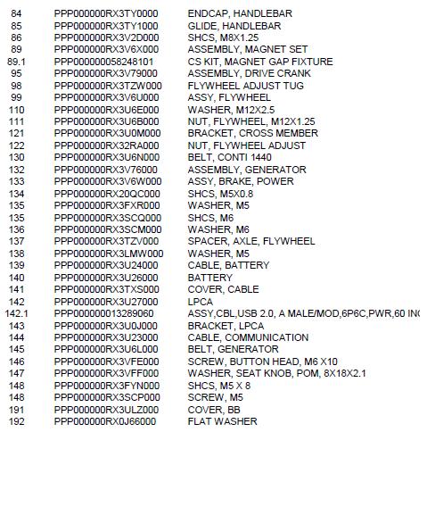
156 149


157 9 Consoles About 9 Consoles About The self-powered Spinner Chrono Power bike models use the Spinner Chrono console and the non-powered Spinner Climb models use the Spinning Studio Console. Select the link for console service and maintenance information: "Spinner Chrono Console" on the facing page "Spinning Studio Console" on page
158 Spinner Chrono Console (Spinner Chrono Power models only) About The Spinner Chrono console is only available on the Spinner Chrono Power model indoor cycle. In addition to the primary workout display information, there is a service/setup mode that allows console configuration setup and service diagnostic tests and cycle software and use information data: Club Parameters: Use Club Parameter settings to choose the type of information you want exercisers to see on the console while working out. Informational Settings: The Information Settings contain the information required when you contact Precor Customer Support including serial numbers, software program versions, odometer and error log summary, and model numbers. Operational Information: The operating Torque, WATTS, and RPM values. Service Tests: Perform tests to help you troubleshoot systems including torque, WATTS, RPM, battery, generator and console display. Console Power The console is powered from the bike generator and does not need batteries to operate. Start pedaling to power ON, continue pedaling to keep the console ON, The console uses power from the 6 Vdc battery to keep the console powered ON for 90 seconds after the pedals have stopped. USB 1 Port The console provides a USB port for program updates, system settings cloning between consoles, to download system information, and download error log data. Active Status Light (ASL 2 ) The console also provides Active Status Light "ASL" functionality to identify the current operating condition and an error log that stores error event codes to help troubleshoot and identify faults that may cause problems with the bike operation.. Note: Refer to the SPINNER CHRONO CONSOLE "Operators Guide" for the latest console installation, operation, and service information. Operator's Guide Getting Started Guide 1 Short for Universal Serial Bus, is an industry standard developed in the mid-1990s that defines the cables, connectors and communications protocols used in a bus for connection, communication, and power supply between computers and electronic devices. 2 Active Status Light: Service and maintenance status light. 151

 and bluetooth wireless heart rate monitor chest straps (however the Polar or Suunto ANT+ brand heart rate monitor chest straps are not supported).")
159 9 Consoles Spinner Chrono Console Features Self-Powered Console: The console is powered from the bike generator and does not require batteries. The backup battery is used to power the console for 90 seconds after the pedals stop. USB port: The console provides a USB port located on the top back of the console to update software ANT+ 1 and bluetooth connectivity: The console supports ANT+ (2.4 GHZ) and bluetooth wireless heart rate monitor chest straps (however the Polar or Suunto ANT+ brand heart rate monitor chest straps are not supported). ASL light: There is an ASL (Active Status Light) maintenance light located at the top back of the console to indicate maintenance and fault status information, see the ASL topic for more information. Error Log: Supports an Error Log and error event codes to help trouble shoot electrical issues, see Troubleshooting Error Code topic. Powering ON the Console To power ON the console, start pedaling the bike. Optional AC Power Adapter: You can also use an optional universal 18 Vdc 3 Amp power supply that plugs into the LPCA 2 board to power the console. This is the same power supply part number (PN or UNIVERSAL AC POWER ADAPTER) that is also used on AMTs. 1 ANT+ (pronounced ant plus) is a wireless protocol for monitoring sensor data such as a person's heart rate or a bicycle's tire pressure 2 Lower PCA board 152


160 Installation and Removal For installation and removal instructions, see the SPINNER CHRONO CONSOLE "Operators Guide", see Operator's Guide. 153


161 9 Consoles Spinner Chrono Console Service/Setup Menu Access Menu Navigation The menus are accessed sequentially by scrolling through the list of menus in a forward or reversed direction using the following console buttons. You cannot directly access a menu item. 154


162 Menus and Settings Note: Refer to the SPINNER CHRONO CONSOLE "Operators Guide", at Operator's Guide, for the latest console menu information. Club Settings Parameters Use the Club Settings to choose the type of information accessible to the exercisers. 155
163 9 Consoles Spinner Chrono Console Information Settings Parameters The Information Settings contain the information required when you contact Precor Customer Support including serial numbers, software program versions, odometer and error log summary, and model numbers. Note: It is possible to record system information and the error log on a properly formatted USB drive. 156
164 Operational Information Service Tests Perform tests to help you troubleshoot systems including torque, WATTS, RPM, battery and generator voltage and amps, and display elements. Press the white button to move from one test to the next. Error Log Information Accessing the Error Log Select the service menu ERROR LOG menu to access the error log information. Menu Description ERROR LOG If there are no errors, there line following the title will be blank. Clearing the Error Log If there are detected error codes, the 5 most recent error codes will be listed. Select CLEAR ERROR menu item to clear the error log. Saving error log codes to an external USB drive The list of all stored error codes (100 maximum) can be downloaded to an external properly formatted USB drive (must be less than 32 G bits). The error log file is downloaded as an excel "CSV" formatted spreadsheet named ERRORLOG.CSV. Instruction to download the stored error log codes 157


165 9 Consoles Spinner Chrono Console 1. Format a USB drive (must be less than 32 G bits) with the following folder structure: Folder structure: C:\Precor\SBK\Log 2. Insert the formatted USB drive into the console USB port. 3. Select the console USB LOGS menu. Wait until the console recognizes the USB drive and the blue button lights up. If the USB drive is not recognized, remove the USB and make sure the USB memory size is not greater than 32 Gbits and the folder structure is properly formatted. 4. Press the blue button to show the YES option and then the white button to select YES. 5. The console will show WAIT while the error log is downloading. 6. Then the console will show PASS when the download has successfully completed. 7. Remove the USB drive. 8. Insert the USB drive into a computer USB port and select the C:\Precor\SBK\Log\ERRORLOG.CSV file. 158

166 Spinning Studio Console About The Spinning Studio Console is used on the Spinner Climb indoor cycle. This console is also used on Precor Spinner Ride, Spinner Shift, and Spinner Rally model indoor cycles. Refer to the SPINNING STUDIO "Owner's Manual" for the latest console installation, use, and service information. Operator's Guide Features Battery Powered Console and Cadence Sensor: The console is powered by 3 - AAA batteries and the Cadence sensor uses a CR2032 lithium coin cell battery. ANT+ 1 connectivity: The console supports ANT+ wireless heart rate monitor chest straps (however the Polar or Suunto ANT+ brand heart rate monitor chest straps are not supported). Program Memory: The console maintains programming code during battery replacement. 1 ANT+ (pronounced ant plus) is a wireless protocol for monitoring sensor data such as a person's heart rate or a bicycle's tire pressure 159
RBK 815 Recumbent Cycle. RBK 815 Bicycle
 RBK 815 Bicycle Warning: This service manual is for use by Precor trained service providers only. If you are not a Precor Trained Servicer, you must not attempt to service any Precor Product; Call your
PRO INDOOR CYCLING BIKE
 PRO INDOOR CYCLING BIKE SF-B901 USER MANUAL IMPORTANT! Please retain owner s manual for maintenance and adjustment instructions. Your satisfaction is very important to us, PLEASE DO NOT RETURN UNTIL YOU
BELT DRIVE PRO INDOOR CYCLING BIKE SF-B901B USER MANUAL
 BELT DRIVE PRO INDOOR CYCLING BIKE SF-B901B USER MANUAL IMPORTANT! Please retain owner s manual for maintenance and adjustment instructions. Your satisfaction is very important to us, PLEASE DO NOT RETURN
SUNNY PRO INDOOR CYCLING BIKE
 SUNNY PRO INDOOR CYCLING BIKE SF-B901 USER MANUAL IMPORTANT! Please retain owner s manual for maintenance and adjustment instructions. Your satisfaction is very important to us, PLEASE DO NOT RETURN UNTIL
Procedure Replacing a Cover
 Procedure 7.1 - Replacing a Cover Cover Removal 1. Remove two screws, one each side, from the front of the top cover. Remove the top cover. See Diagram 7.1. Diagram 7.1 - RBK 815 Covers Top Cover Left
S-Drive Performance Trainer
 S-Drive Performance Trainer SERVICE MANUAl Table of contents CHAPTER 1: Serial number location... 1 CHAPTER 2: Important Safety instructions 2.1 Read and Save These Instructions... 2 2.2 Before Getting
GENERAL INFO TROUBLE SHOOTING. Version 1.1
 GENERAL INFO TROUBLE SHOOTING Version 1.1 GENERAL INFO Before beginning any exercise, please consult your physician Wipe off the cycle after EVERY use. If necessary, use water in a spray bottle and a tissue
ASSEMBLY INSTRUCTIONS / OWNERS MANUAL AIR BIKE AB-1
 AIR BIKE AB- ASSEMBLY INSTRUCTIONS / OWNERS MANUAL IMPORTANT : READ ALL ASSEMBLY INSTRUCTIONS AND SAFETY PRECAUTIONS BEFORE USING THIS PRODUCT. REFERENCE ALL SAFETY GUIDELINES AND WARNING LABELS. RETAIN
Check the wires going to the back of the computer, if the wires are secure and console will not start see step b.
 ELECTRONIC TROUBLESHOOTING 1. PROBLEM: Console LED's will not light, console will not power up The bike must be pedaled at greater than 50 RPM while Check the wires going to the back of the computer, if
C524, C524i Elliptical Fitness Crosstrainer
 C524, C524i Elliptical Fitness Crosstrainer Warning: This service manual is for use by Precor trained service providers only. If you are not a Precor Trained Servicer, you must not attempt to service any
C542i Elliptical Fitness Crosstrainer
 C542i Elliptical Fitness Crosstrainer Warning: This service manual is for use by Precor trained service providers only. If you are not a Precor Trained Servicer, you must not attempt to service any Precor
C556, C556i Navy Elliptical Fitness Crosstrainer
 C556, C556i Navy Elliptical Fitness Crosstrainer Warning: This service manual is for use by Precor trained service providers only. If you are not a Precor Trained Servicer, you must not attempt to service
BELT DRIVE INDOOR CYCLING BIKE
 BELT DRIVE INDOOR CYCLING BIKE SF-B1002 USER MANUAL IMPORTANT: Read all instructions carefully before using this product. Retain owner s manual for future reference. For customer service, please contact:
C554i Elliptical Fitness Crosstrainer
 C554i Elliptical Fitness Crosstrainer Warning: This service manual is for use by Precor trained service providers only. If you are not a Precor Trained Servicer, you must not attempt to service any Precor
Cybex Arc Trainer Owner s & Service Manual. 7 - Service
 7 - Service Table of Contents......... iii Warnings/Cautions All warnings and cautions listed in this chapter are as follows:! WARNING: All maintenance activities shall be performed by qualified personnel.
9.17, 9.17si Treadmill
 9.17, 917si Treadmill 9.17, 9.17si Treadmill Warning: This service manual is for use by Precor trained service providers only. If you are not a Precor Trained Servicer, you must not attempt to service
Magnetic Elliptical Trainer
 Magnetic Elliptical Trainer ITEM NO.: 400 OWNER S MANUAL IMPORTANT: Read all instructions carefully before using this product. Retain this owner s manual for future reference. The specifications of this
EASY ADJUSTABLE SEAT RECUMBENT BIKE
 EASY ADJUSTABLE SEAT RECUMBENT BIKE SF-RB4616 USER MANUAL IMPORTANT! Please retain owner s manual for maintenance and adjustment instructions. Your satisfaction is very important to us, PLEASE DO NOT RETURN
9.2, 9.2s, 9.20, 9.20s Treadmill
 9.2, 9.2s, 9.20, 9.20s Treadmill Warning: This service manual is for use by Precor trained service providers only. If you are not a Precor Trained Servicer, you must not attempt to service any Precor Product;
POLARIS 4500 HD WINCH KIT
 POLARIS 4500 HD WINCH KIT P/N 2883860 APPLICATION Verify accessory fitment at Polaris.com. BEFORE YOU BEGIN Read these instructions and check to be sure all parts and tools are accounted for. Please retain
VHM-P (Non-Locking) and VHM-PL (Locking) Variable Height Arm with Slide-In Mounting Plate
 and VHM-PL (Locking) Variable Height Arm with Slide-In Mounting Plate") 3875 Cypress Drive Petaluma, CA 94954 800.228.2555 +1.707.773.1100 Fax 707.773.1180 www.gcx.com VHM-P (Non-Locking) and VHM-PL (Locking) Variable Height Arm with Slide-In Mounting Plate (Refer to qualified
3875 Cypress Drive Petaluma, CA 94954 800.228.2555 +1.707.773.1100 Fax 707.773.1180 www.gcx.com VHM-P (Non-Locking) and VHM-PL (Locking) Variable Height Arm with Slide-In Mounting Plate (Refer to qualified
Final Assembly Instructions Portside Cruiser
 Final Assembly Instructions Portside Cruiser Thank you for buying your new bicycle from L.L.Bean. Read these instructions carefully before beginning the final assembly. Prior to shipping, our expert cycling
C960, C962, C964 Treadmill
 C960, C962, C964 Treadmill Warning: This service manual is for use by Precor trained service providers only. If you are not a Precor Trained Servicer, you must not attempt to service any Precor Product;
ACCORD ELLIPTICAL TRAINER ITEM NO: 93470
 ACCORD ELLIPTICAL TRAINER ITEM NO: 93470 OWNER S MANUAL IMPORTANT: Read all instructions carefully before using this product. Retain this owner s manual for future reference. The specifications of this
TABLE OF CONTENTS CHAPTER 1: SAFETY PRECAUTIONS. 2.3 COMPONENTS in the Hardwars Kit COMPONENTS on the Product SETP SETP2...
 TABLE OF CONTENTS CHAPTER : SAFETY PRECAUTIONS. SAFETY PRECAUTIONS... CHAPTER 2: INSTRUCTIONS 2. DIMENSIONS... 2.2 LIST OF PARTS... 2.3 COMPONENTS in the Hardwars Kit.... 2.4 COMPONENTS on the Product...
Owners Manual 1 E720
 Owners Manual 1 E720 Training with E720 2 Contents 1. Contents of E720 Box. 2. E720 assembly instructions. 3. Tank filling and water treatment. 4. Long term water treatment and basic operation. As with
XINGGUI Elliptical Cross Trainer
 XINGGUI Elliptical Cross Trainer ITEM NO.: 93040 OWNER S MANUAL IMPORTANT: Read all instructions carefully before using this product. Retain this owner s manual for future reference. The specifications
3875 Cypress Drive Petaluma, CA Fax
 3875 Cypress Drive Petaluma, CA 94954 800.228.2555 +1.707.773.1100 Fax 707.773.1180 www.gcx.com VHM-P (Non-Locking) Variable Height Arm with Fixed Angle Front End for Flat Panel / Keyboard Bracket (L Brackets
Core Health & Fitness. Schwinn SC Power SERVICE MANUAL
 Core Health & Fitness Schwinn SC Power SERVICE MANUAL TABLE OF CONTENTS Click any text to jump to section PRODUCT SPOTLIGHT... 3 OTHER MANUALS... 4 ACCESSORIES... 5 Cranks & Pedals... 5 REPLACEMENT PROCEDURES...
VHM-P (Non-Locking) Variable Height Arm with VESA Mounting Plate for 75 x 75mm or 100 x 100mm applications
 Variable Height Arm with VESA Mounting Plate for 75 x 75mm or 100 x 100mm applications") 3875 Cypress Drive Petaluma, CA 94954 800.228.2555 +1.707.773.1100 Fax 707.773.1180 www.gcx.com VHM-P (Non-Locking) Variable Height Arm with VESA Mounting Plate for 75 x 75mm or 100 x 100mm applications
3875 Cypress Drive Petaluma, CA 94954 800.228.2555 +1.707.773.1100 Fax 707.773.1180 www.gcx.com VHM-P (Non-Locking) Variable Height Arm with VESA Mounting Plate for 75 x 75mm or 100 x 100mm applications
Schwinn IC Bikes. Assembly Manual. Evolution, Evolution SR. Nautilus Bowflex Schwinn Fitness Pearl Izumi StairMaster Universal Nautilus Institute
 Schwinn IC Bikes Evolution, Evolution SR Nautilus Bowflex Schwinn Fitness Pearl Izumi StairMaster Universal Nautilus Institute PN001-7189 (12/11/2007) Table of Contents Product Specifications 2 Safety
GPS AutoSteer System Installation Manual
 GPS AutoSteer System Installation Manual John Deere Track Supported Models 8295RT 8320RT 8345RT PN: 602-0255-01-A LEGAL DISCLAIMER Note: Read and follow ALL instructions in this manual carefully before
CALIFORNIA TRIMMER MOWER MAINTENANCE MANUAL
 CALIFORNIA TRIMMER MOWER MAINTENANCE MANUAL 2 Table of Contents Section 1: General Information Page Handle Assembly Instructions 4 Maintenance All Models 6 Oil Change Procedures All Models 9 Height Adjustment
INSTALLATION INSTRUCTIONS
 Accessory Application Publication No. INSTALLATION INSTRUCTIONS HEATED GRIPS P/N 08T71-MKK-D00 After 17 CRF1000L/LD Honda Dealer: Please give a copy of these instructions to your customer. MII 16656 Issue
IMPORTANT! DO NOT THROW AWAY THE SHIPPING CARTON AND PACKING MATERIAL
 Operator s Manual IMPORTANT! DO NOT THROW AWAY THE SHIPPING CARTON AND PACKING MATERIAL ii Table of Contents Operator Safety... 1 Introduction... 2 Unpacking and Setup... 3 Unpacking... 3 Setup... 4 ROCKET
CARE AND MAINTENANCE INSTRUCTIONS
 STRONG. SMART. BEAUTIFUL. CARE AND MAINTENANCE INSTRUCTIONS In order to maximize life span, and minimize down time, all MATRIX equipment requires regular cleaning, and maintenance items performed on a
NOTE: DISCONNECT MAIN POWER LOCK OUT AND TAG BEFORE PERFORMING ANY PROCEDURES IN THIS SECTION.
 M E C H A N I C A L S E T U P & A D J U S T M E N T S NOTE: DISCONNECT MAIN POWER LOCK OUT AND TAG BEFORE PERFORMING ANY PROCEDURES IN THIS SECTION. NOTE: All adjustments should be made with the sealer
OWNERS MANUAL. ULTRA Single-Station Strength G7-S13 Chest Press
 OWNERS MANUAL ULTRA Single-Station Strength G7-S13 Chest Press Table Of Contents Safety, General Care & Maintenence...3 Getting Started (Product Specifications)...5 Assembly Information...6 Markings...7
OWNERS MANUAL. ULTRA Single-Station Strength G7-S34 Seated Row
 OWNERS MANUAL ULTRA Single-Station Strength G7-S34 Seated Row Table Of Contents Safety, General Care & Maintenence...3 Getting Started (Product Specifications)...5 Assembly Information...6 Markings...7
GPS Steering System Installation Manual
 GPS Steering System Installation Manual Supported Vehicles Challenger Massey Ferguson AGCO MT-645C, MT-645D MF-8650 DT-205B MT-655C, MT-655D MF-8660 DT-225B MT-665C, MT-665D MF-8670 DT-250B MT-675C, MT-675D
LS8.0T Service Manual
 LS8.0T Service Manual 1 TABLE OF CONTENTS CHAPTER 1: SERIAL NUMBER LOCATION...3 CHAPTER 2: PREVENTATIVE MAINTENANCE 2.1 Preventative Maintenance. 4 2.2 Tension and Centering the Running Belt....6 CHAPTER
Owners Manual E820/E920
 Owners Manual E820/E920 Wheelchair Accessible Training with E820/E920 2 Contents 1. Contents of E820/920 Box. 2. E820/E920 assembly instructions. 3. E820/E920 Control arm. 4. E920 Adjustable crank arms.
Table of Contents. Assembly Instructions 1. Assembly Figure. 4
 Table of Contents Assembly Instructions 1 Assembly Figure. 4 Maintenance Instructions.. 5 Daily. 5 Weekly.. 5 Lubricating the Chain... 5 Check Friction Belt... 6 Clean Bike.6 Monthly.... 6 Chain Guard
905e, 9.1, 9.10 Treadmill
 905e, 9.1, 9.10 Treadmill Warning: This service manual is for use by Precor trained service providers only. If you are not a Precor Trained Servicer, you must not attempt to service any Precor Product;
Read these instructions thoroughly before attempting to install this option.
 Rewind Option Kit Installation Instructions This kit includes the parts and documentation necessary to install the Media Rewind option into the following printers: 0XiIIIPlus, 0 dpi 0XiIIIPlus, 00 dpi
RECUMBENT BIKE WITH ARM EXERCISER
 RECUMBENT BIKE WITH ARM EXERCISER SF-RB4631 USER MANUAL IMPORTANT! Please retain owner s manual for maintenance and adjustment instructions. Your satisfaction is very important to us, PLEASE DO NOT RETURN
INSTALLATION MANUAL. Level of Difficulty. Parts List. Product Image. Tools Required. Notes and Maintenance. Torque Specifications.
 INSTALLATION MANUAL Parts List 1 Bull bar 2 Upper frame mounting bracket 1 Driver / left lower frame mounting bracket 1 Passenger / right lower frame mounting bracket 2 Button head bolt, 6mm 4 Flat washer,
Installation Manual TWM Performance Short Shifter Cobalt SS/SC, SS/TC, HHR SS, Ion Redline and Saab 9-3
 Page 1 Installation Manual TWM Performance Short Shifter Cobalt SS/SC, SS/TC, HHR SS, Ion Redline and Saab 9-3 Please Note: It is preferable to park on a flat surface, as you will have to engage and disengage
ADJUSTABLE TENSION MAGNETIC TREADMILL
 ADJUSTABLE TENSION MAGNETIC TREADMILL SF-T7614 USER MANUAL IMPORTANT : Read all instructions carefully before using this product. Retain this manual for future reference. For customer service, contact
This is the Unpacking Guide for the Optibike Pioneer Allroad electric bicycle. The Guide provides information required to remove the Allroad from the
 This is the Unpacking Guide for the Optibike Pioneer Allroad electric bicycle. The Guide provides information required to remove the Allroad from the box and assemble it. If you have not assembled a bicycle
with Wireless Power Meter
 17280 Woodinville-Redmond RD NE Suite 800 Woodinville WA 98072 425.402.4062 cascadehealthandfitness.com with Wireless Power Meter Thank you for purchasing the CASCADE FLUIDPro trainer and wireless power
BRF 700 BRF 701. Fan Bike OWNER S MANUAL. * This item is for consumer use only and it is not meant for commercial use.
 BRF 700 Fan Bike BRF 701 * This item is for consumer use only and it is not meant for commercial use. OWNER S MANUAL General Information Safety Before you undertake any exercise program, please be sure
Rescue Hoist Ground Support Equipment Electric Version
 Rescue Hoist Ground Support Equipment Electric Version Introduction and Training Information Overview of Training Program Introduction of system Benefits to the Users Theory of Operation When to use the
w w w. h d o n l i n e s h o p. d e CRUISE CONTROL KIT GENERAL INSTALLATION -J04064 REV Kit Number Models Additional Parts Required
 -J006 REV. 006-08- CRUISE CONTROL KIT GENERAL Kit Number 7796-07 Models For the most up-to-date model fitment information, please see the product label or www.harley-davidson.com. Additional Parts Required.
(Refer to qualified personnel)
") 3875 Cypress Drive Petaluma, CA 94954 800.228.2555 +1.707.773.1100 Fax 707.773.1180 www.gcx.com Installation Guide VHM-P (Non-Locking) and VHM-PL (Locking) Variable Height Arm (Slide-Above-Arm Configuration)
3875 Cypress Drive Petaluma, CA 94954 800.228.2555 +1.707.773.1100 Fax 707.773.1180 www.gcx.com Installation Guide VHM-P (Non-Locking) and VHM-PL (Locking) Variable Height Arm (Slide-Above-Arm Configuration)
Depress each tab as you pull the bezel off. The bezels are tight. L.H. shown.
 2013-2014 Ford Mustang V6 & Boss 302 Lower Valance Fog Light Kit Parts List: Quantity: Tool List: Fog light & bulb with bracket 2 Flat head & Phillips screwdriver Black bezels 2 Ratchet & Socket set OR
C762, C764, C764i Stairclimber
 C762, C764, C764i Stairclimber Warning: This service manual is for use by Precor trained service providers only. If you are not a Precor Trained Servicer, you must not attempt to service any Precor Product;
CONVERSION KIT. User Manual AKLO. English. Please read through carefully before beginning your conversion
 CONVERSION KIT User Manual AKLO English Please read through carefully before beginning your conversion INSTALLATION PROCESS Before beginning your conversion, there are a couple things you can do that will
C842i, C846i Bicycle
 C842i, C846i Bicycle Warning: This service manual is for use by Precor trained service providers only. If you are not a Precor Trained Servicer, you must not attempt to service any Precor Product; Call
LEXUS GS 350/450h ILLUMINATED DOOR SILLS Preparation
 Preparation Part Number: PT922-30120 (GS350) PT922-30130 (GS450h) NOTE: Part number of this accessory may not be the same as the part number shown. Kit Contents Item # Quantity Req'd. Description 1 1 Illuminated
Page 1. File: Motolight caliper one-piece Harley Date: 8/15/2006
 Page 1 Harley-Davidson FL Caliper Mount Installation One-piece mounting brackets You should allow about two to three hours for installation. We suggest you use a well-lighted space for installation. PLEASE
Reproduction or other use of this Manual, without the express written consent of Vulcan, is prohibited.
 SERVICE MANUAL ELECTRIC BRAISING PANS (30 & 40 GALLON) VE30 VE40 ML-126849 ML-126850 VE40 SHOWN - NOTICE - This Manual is prepared for the use of trained Vulcan Service Technicians and should not be used
GENUINE PARTS INSTALLATION INSTRUCTIONS
 GENUINE PARTS INSTALLATION INSTRUCTIONS 1. 2. 3. 4. DESCRIPTION: Illuminated Kick Plate Kit APPLICATION: Murano PART NUMBER: 999G6 C2000, 999G6 C2100, 999G6 C2200 999Q9 AY001 - Accessory Service Connector
INSTALLATION INSTRUCTIONS for HI-1 and HI-2 MOTORCYCLE IGNITIONS. Part Numbers and INTRODUCTION COIL AND SPARK PLUG CABLE CONSIDERATIONS
 INSTALLATION INSTRUCTIONS for HI- and HI- MOTORCYCLE S Part Numbers 8-000 and 8-000 CAUTION: READ INSTRUCTIONS CAREFULLY BEFORE STARTING INSTALLATION INTRODUCTION Crane HI- and HI- ignition systems are
Maintenance Information
 80234313 Edition 1 June 2006 Air Grinder, Die Grinder, Sander and Belt Sander Series G1 (Angle) Maintenance Information Save These Instructions WARNING Always wear eye protection when operating or performing
Installation Manual. AutoSteer. Gleaner Combine. AutoGuide 2 Steer Ready. Supported Models A66 A76 R66 R76 S67 S77 PN: A
 Installation Manual AutoSteer Gleaner Combine AutoGuide 2 Steer Ready Supported Models A66 A76 R66 R76 S67 S77 PN: 602-0312-01-A LEGAL DISCLAIMER Note: Read and follow ALL Instructions in this manual carefully
INSTALLATION INSTRUCTIONS
 Accessory Application Publication No. INSTALLATION INSTRUCTIONS S ATTACHMENT KIT P/N 08T70-MJW-D90 After 15 CB500X/XA Honda Dealer: Please give a copy of these instructions to your customer. MII 15802
INSTALLATION INSTRUCTIONS
 Accessory Application Publication No. INSTALLATION INSTRUCTIONS ATTACHMENT P/N 08T70-MGZ-D80 CB500X/XA MII 14565 Issue Date May 2013 PARTS LIST KIT Sold separately (1) (2) (4) (2) (1) (3) BOOT (1 piece.)
Multistrada (MTS) Tank Installation Notes. Tools Required. Phase 1: Remove Fairings. Phase 2: Remove Fuel Tank
 Tank Installation Notes. Tools Required. Phase 1: Remove Fairings. Phase 2: Remove Fuel Tank") The California Cycleworks MTS tank provides an aftermarket alternative to the OEM nylon fuel tanks as used on aircooled Desmodue Ducati Multistrada 1100, 1000, and 620 models. This fuel tank is NOT for
The California Cycleworks MTS tank provides an aftermarket alternative to the OEM nylon fuel tanks as used on aircooled Desmodue Ducati Multistrada 1100, 1000, and 620 models. This fuel tank is NOT for
TABLE OF CONTENTS CHAPTER 1.. CHAPTER 2.. CHAPTER 3.. CHAPTER 4.. CHAPTER 5.. CHAPTER 6.. CHAPTER 7.. CHAPTER 8.. CHAPTER 9..
 CHAPTER 1.. CHAPTER 2.. CHAPTER 3.. CHAPTER 4.. CHAPTER 5.. CHAPTER 6.. CHAPTER 7.. CHAPTER 8.. CHAPTER 9.. CHAPTER 10... CHAPTER 11... CHAPTER 12... TABLE OF CONTENTS SPECIFICATIONS:...1 PRECAUTIONS:...2
Owner s Manual for 16 Slider
 Owner s Manual for 16 Slider This manual contains important safety, assembly, operation and maintenance information. Please read and fully understand this manual before operation. Save this manual for
C546i Self Powered Elliptical Fitness Crosstrainer (version 2, serial codes AA32, AAAJ, ADEE)
") C546i Self Powered Elliptical Fitness Crosstrainer (version 2, serial codes AA32, AAAJ, ADEE) Warning: This service manual is for use by Precor trained service providers only. If you are not a Precor Trained
C546i Self Powered Elliptical Fitness Crosstrainer (version 2, serial codes AA32, AAAJ, ADEE) Warning: This service manual is for use by Precor trained service providers only. If you are not a Precor Trained
INSTALLATION INSTRUCTIONS FOR DSP9600/9100 WHEEL BALANCER
 Form 5063T, 06-05 Supersedes Form 5063T, 02-04 INSTALLATION INSTRUCTIONS FOR DSP9600/9100 WHEEL BALANCER This document provides the information needed to install the DSP9600/9100 Wheel Balancer. NOTE:
160S Rewind Option Kit Installation Instructions
 Installation Instructions GENERAL This kit includes the parts and documentation necessary to install the Media Rewind Option into the Zebra 160S printer. Read these instructions thoroughly before attempting
Southwest Windpower Instruction Sheet AIR-X Circuit Replacement Kit
 Southwest Windpower Instruction Sheet AIR-X Circuit Replacement Kit Tools Required 5 / 32 Hex key 5 / 16 Hex key 7 / 64 Hex key Standard screwdriver Pair of external snap ring pliers Rubber mallet Hammer
HIGH RISE POWER ANGLE KIT
 HIGH RISE POWER ANGLE KIT P/N 33-0100 OWNER S MANUAL Application HIGH RISE PUSH TUBE 33-0000 & 34-0000 ATTENTION DEALER: CUSTOMER MUST RECEIVE A COPY OF THIS MANUAL AT THE TIME OF SALE. Before you begin,
2013 Elite T4000 (TM461C) Service Manual
 Service Manual") 2013 Elite T4000 (TM461C) Service Manual 1 TABLE OF CONTENTS CHAPTER 1: SERIAL NUMBER LOCATION...3 CHAPTER 2: PREVENTATIVE MAINTENANCE 2.1 Preventative Maintenance. 4 2.2 Tension and Centering the Running
2013 Elite T4000 (TM461C) Service Manual 1 TABLE OF CONTENTS CHAPTER 1: SERIAL NUMBER LOCATION...3 CHAPTER 2: PREVENTATIVE MAINTENANCE 2.1 Preventative Maintenance. 4 2.2 Tension and Centering the Running
Installation Guide VHM Wall Mount Kit for Philips MX600/700/800 and MP60/70 IntelliVue
 Installation Guide VHM Wall Mount Kit for Philips MX600/700/800 and MP60/70 IntelliVue The purpose of this guide is to: 1. Describe attachment of Table Top Mount to Mounting Adapter (page 2). 2. Describe
TC1000 Service Manual SALES: CUSTOMER SERVICE:
 TC1000 Service Manual SALES: 800-278-3933 CUSTOMER SERVICE: 800-745-1373 Table of Contents Section Page I. Overview 2 II. Troubleshooting Tables 3 III. Maintenance Procedures Procedure 1 Removal and Reinstallation
INSTALLATION INSTRUCTIONS
 Accessory Application Publication No. INSTALLATION INSTRUCTIONS HEATED GRIPS ATTACHMENT KIT P/N 08T70-MJL-D30 2014-2015 NC700X/XD Honda Dealer: Please give a copy of these instructions to your customer.
Special Chemicals VDC approved cleaner. General Applicability All Scion iq models, including 10 Year Anniversary Edition.
 Preparation Part Number: PT296-00140 or PT296-00142 (Extension Box w/aha) Kit Contents Item # Quantity Req. Description 1 1 Extension Module w/bt cable 2 1 DA/Ext Harness 3 1 GPS Antenna kit 4 4 Screws
MKVI Jetta Fog Light Kit
 MKVI Jetta Fog Light Kit Part Number VW Jetta Fog Light Installation This tutorial is provided as a courtesy by ECS Tuning. Proper service and repair procedures are vital to the safe, reliable operation
Final Assembly Instructions: Bikes with Threadless Headsets
 Final Assembly Instructions: Bikes with Threadless Headsets Thank you for buying your new bicycle from L.L.Bean. Read these instructions carefully before beginning the final assembly. Prior to shipping,
Maintenance Information
 80234313 Edition 2 May 2014 Air Grinder, Die Grinder, Sander and Belt Sander Series G1 (Angle) Maintenance Information Save These Instructions Product Safety Information WARNING Failure to observe the
Parts List Continues on Next Page
 Assembly Instructions and Owner s Manual Description: Quantum Hardcoated Polycarbonate UTV Windshield, Wash n Wipe Full Size Model: Part Number: N30202 Installation Time: 60 min Polaris RZR 800, Round
FIG. 3 BRACKET INSTALLATION. i a. e h f FIG. 4 STATOR OFFSET BRACKET REMOVE OEM SPACER. REPLACE WITH BRACKET 3.
 700510 IG. 3 BRACKET INSTALLATION E D 11 C B i a b c d e h f g A B C A IG. 4 STATOR OSET BRACKET 14 G REMOVE OEM SPACER. REPLACE WITH BRACKET 3. 9 G 8 2 4 3 DewEze Clutch Pump Kit 700510 ord 6.7L, AA Pump,
Self-Adjust Clutch Installation Guide
 Self-Adjust Clutch Installation Guide 0 STOP! READ CAREFULLY BEFORE INSTALLING CLUTCH This clutch must be installed by a qualified installer. Improper installation or failure to replace or resurface the
INSTALLATION INSTRUCTIONS
 INSTALLATION INSTRUCTIONS Accessory Accessory Hands Free Link Application 2008 ACCORD 2 AND 4-DOOR Publications No. AII 38281 Issue Date NOV 2007 PARTS LIST Attachment Kit P/N 08E02-TA0-100 trim retainer
Owners Manual. Wheelchair Accessible
 Owners Manual Wheelchair Accessible Contents 1. Contents of E920 Box. 2. E920 Assembly Instructions. 3. E920 Control Arm. 4. E920 Slider Arm Kit. 5. Tank Filling and Water Treatment. CAUTION 6. Long Term
Section 5: Parts Replacement
 Section 5: Parts Replacement Should the STAR TRAC 4500 Treadmill experience a problem requiring replacement of a specific part, the following procedures will help and instruct in the replacement of major
BX-308 BAM-1020 SERVICE TOOL KIT MANUAL
 BX-308 BAM-1020 SERVICE TOOL KIT MANUAL Met One Instruments, Inc 1600 Washington Blvd. Grants Pass, Oregon 97526 Telephone 541-471-7111 Fax: 541-471-7116 BX-308-9800 Copyright 2008 Met One Instruments,
NTB-550 Manual. Contents
 1 NTB-550 Manual Please read this Manual before using the Machine. You will need to know the safety instructions, System Settings, Wheel Parameters Input and Calibration process before you can properly
OWNERS MANUAL. ULTRA Single-Station Strength G7-S42 Triceps Press
 OWNERS MANUAL ULTRA Single-Station Strength G7-S42 Triceps Press Table Of Contents Safety, General Care & Maintenence... 3 Getting Started (Product Specifications)... 5 Assembly Information... 6 Parts
Installation Guide CLAAS Lexion Combines with 9 inch Elevators
 Installation Guide CLAAS Lexion Combines with 9 inch Elevators 955614_01 4/17 1 Table of Contents System Overview 3 Quick Start Guide 4 Flow Sensor Installation 5 Hydraulic Elevator Adjustment Kit Installation
Job Sheet 6 Installing the Combiner Box
 Job Sheet 6 Installing the Combiner Box The Combiner Box The combiner box used in this course can combine photovoltaic (PV) solar sub-array strings that are up to 150 V DC each and up to 120 A total. Using
9.33i, 9.35i Treadmill
 9.33i, 9.35i Treadmill Warning: This service manual is for use by Precor trained service providers only. If you are not a Precor Trained Servicer, you must not attempt to service any Precor Product; Call
ASSEMBLY MANUAL 9GU - COMMERCIAL UPRIGHT BIKE
 ASSEMBLY MANUAL 9GU - COMMERCIAL UPRIGHT BIKE IMPORTANT SAFETY INSTRUCTIONS Read this Owner s Manual and follow it s instructions carefully before using the machine. Make sure that it is properly assembled
Foldable Semi-Recumbent Bike
 Foldable Semi-Recumbent Bike IMPORTANT: Read all instructions carefully before using this product. Retain this owner s manual for future reference. The specifications of this product may vary from this
GENUINE ACCESSORIES INSTALLATION INSTRUCTIONS. ITEM QTY DESCRIPTION Usage Chart Service Part Number. 1 1 Mirror Assembly w/ Compass 1
 AUTO PART NUMBER: 0000 8C P4 (DIO)/ 0000 89 P25 (PIO) REQUIRED COMPONENTS: INSTALLATION KIT: 2 SA Harness - 2 Conductor 3 0 Wire Ties 4 Wire Cover 5 A-Pillar Tether Clip (D09W-6862) 6 3 Foam Tape 7 3 Electro-Tap(wire
BRF 700 Fan Bike. * This item is for consumer use only and it is not meant for commercial use.
 BRF 700 Fan Bike * This item is for consumer use only and it is not meant for commercial use. OWNER S MANUAL This page intentionally left blank General Information Safety Before you undertake any exercise