Innovative Power Transmission. Tooth Centre Distance. Curved Tooth Couplings High-Speed Series. owner s choice
|
|
|
- Giles Gallagher
- 5 years ago
- Views:
Transcription


1 Innovative Power Transmission Tooth Centre Distance Curved Tooth Couplings High-Speed Series owner s choice


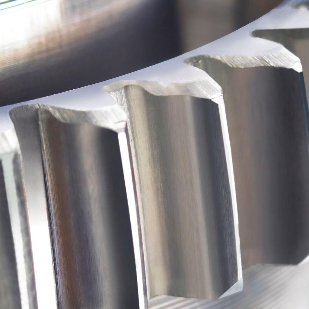
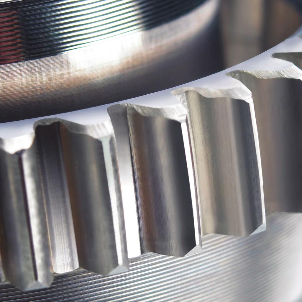
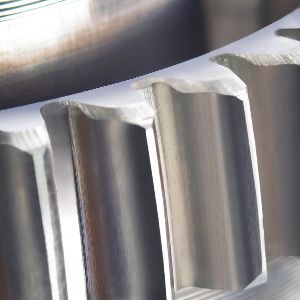
2 Curved Tooth Couplings High-Speed Range Safety and Reliability The safety and reliability of machine installations depends to a great extent on the type and quality of the couplings used. This is even more so where the couplings have to satisfy special requirements. Curved Tooth Couplings Curved tooth couplings in a wide variety of designs have proven themselves over decades in all fields of industrial engineering. The versatility of this ingenious drive element is shown in a comprehensive range of construction series, offering a solution for even the most unusual applications. Systematic structuring according to quality features and application-related criteria ensures optimum adaptation of the coupling design to the specific application. New Development The ZT coupling series has been newly developed for high and very high speeds. It has its origins in the proven highspeed coupling series of RENK and TACKE and offers the best of what is currently possible in the field of gear cou p - lings. The evolution of this coupling range is based on more than 75 years of experience in the development and manufacture of top-quality drive elements using state-of-the-art technology and most advanced production facilities. Hardened and Ground The external and internal gear teeth are hardened and ground. This ensures high percentage contact areas and thus high performance combined with small dimensions. Maximum precision in the manufacturing of all parts is the guarantee for exceptionally good running quality under all operating conditions. Owing to its low weight and high efficiency, this coupling particularly lends itself for use in installations involving flexible shaft lines which are susceptible to vibrations. 2 3 Gear tooth grinding machine 2 Gear tooth shaping machine while producing the internal teeth 3 Hubs of the curved tooth coupling Type VLBGkT 200 spec. for use in vertical thruster drives 4 Gear tooth milling machine with automatic work piece feed 4 2 RENK Aktiengesellschaft, Rheine Works Phone: Fax: and


3 Single Tooth Injection Lubrication Single tooth injection lubrication with continuous lubricant supply provides a maximum of operating reliability combined with a minimum of maintenance. The deposition of centrifugally separated-out oil components is reliably prevented by the design of the coupling parts. This type of lubrication is prescribed for all the coupling series described in this catalogue. Upon request, the couplings can also be supplied with guards being equipped with integrated injection nozzles. The oil supply can be provided by a separate lube oil system or by the installation s own central lubrication station. Quick Availability This is ensured by permanent stock-keeping of all components requiring complex production processes. Couplings which do not require any additional parts such as spacers or intermediate shafts are therefore available from stock at short notice. Depending on the coupling series, this applies to hub bores up to a diameter of 280 mm. Additional Tasks The couplings can perform additional tasks if special parts or additional attachments are installed. These include retaining rings to axially lock generator or motor shafts equipped with floating bearings, as well as insulating bushes and washers to interrupt leakage currents in electrical installations. The combination with torque metering shafts of various designs or the installation of safety elements ensures safe monitoring and protection of the installations during operation. In addition, all coupling series can be supplied as customized designs to fulfil specific requirements. 2 Key-seating machine 2 Cut-away model of a curved tooth coupling Type ZTNH D measuring machine 4 Set-up of a gear cutting machine 4 3 RENK Aktiengesellschaft, Rheine Works Phone: Fax: and
4 Application and Quality Features Application Features Quality Features Construction Series Page High and extremely high speeds Flexible rotors susceptible to vibrations Extended demands on the running performance, in particular in the idle and partial load ranges Very low axial forces High safety against overload Safe interchangeability of components at a high quality level Design according to API 67 Tooth tip centred Single tooth injection lubrication Nitrided and ground internal and external teeth Gear teeth quality Q = 4 according to DIN 3962 Low weight High quality standard in terms of concentricity and balance quality High-strength material Slightly crowned external gear teeth Flank hardness of internal and external teeth > 600 HV Surface finish R a 0.8 µm Reproducible dimensions For highest demands ZTNH 6 7 ZTKH 6 7 ZTF 8 9 ZTFK 8 9 ZTFR 8 9 ZTFKR 8 9 ZTA 0 ZTAK 0 ZTN 2 3 ZTK 2 3 High speeds Stiff rotors not susceptible to vibrations Low axial forces High safety against overload Safe interchangeability of components Design according to API 67 Tooth tip centred Single tooth injection lubrication Nitrided internal and external gear teeth Gear teeth quality Q = 6-7 according to DIN 3962 High quality standard in terms of concentricity and balance quality Quenched and tempered alloy steel Crowned external gear teeth Flank hardness of internal and external gear teeth > 600 HV Surface finish R a 3.2 µm For high demands TF 4 5 TFH 6 7 THB 8 Medium speeds Stiff rotors not susceptible to vibrations High safety against overload Safe interchangeability of components Low axial forces Tooth tip centred Single tooth injection lubrication Natural hard internal and external gear teeth Gear teeth quality Q = 7-8 according to DIN 3962 Quenched and tempered steel Crowned external gear teeth Surface finish R a 3.2 µm For medium demands TSB 9 TSR 20 TSBL 2 TRL 22 TRG 23 Technical Annex Distance plates and coupling guards Special designs Shaft-hub connections 28 Calculation formulae and tables RENK Aktiengesellschaft, Rheine Works Phone: Fax: and
5 Coupling Selection and Size Determination Schematic representation to determine the misalignment values Axis of rotation 2 (coupling connection) Axis of rotation (shaft) Coupling selection and size determination I. Selection on basis II. Size determination accor- III. Selection according of the application ding to power rating PN n to local site and quality features Shock load conditions on page 4 Short circuit load Length Bore diameter Misalignment values Operating speed according to table Result: Result: Result: Coupling Series Coupling size Coupling type Tooth centre distance lo ΔK r = radial misalignment, mm ΔK w = angular misalignment, min. ΔK r = radial misalignment per mm ΔK a = axial misalignment, mm tooth centre distance, mm Table Service Factor K Constant torque:.50 (turbine, boiler feed pump, centrifugal compressor) Design according to API Minor torque fluctuations 2.00 The Service Factor K is applicable for drives including soft starting electric motors, steam turbines or gas turbines. For applications involving high torque fluctuations, alternating torques or reversing operation, please consult RENK AG, Rheine Works. Misalignment Values Speed Factor f ΔKr ΔKw ΔKa ZTNH ZTF TF TSB TSB ZTKH ZTFK TFH TSR TSR ΔKr ZTA THB TSBL TSBL ΔKr = lo ZTAK TRL TRL ZTN TRG TRG ZTK up to over mm minutes size size , , , , , ,8 0, ,90 0, ,80 0,90 0, Upon request, 0,75 0,94 0,79 0, special measures 0,67 0,83 0,70 0, required 0,60 0,75 0,63 0, ,55 0,68 0,57 0, ,50 0,63 0,52 ΔKw perm in minutes 0 24 See dimension table, dimension S ΔKa perm S ± ΔKa ± ΔKa Misalignment In practice, misalignments mostly occur in combined form. The angular misalignment ΔK w of the coupling connection results from the radial misalignment ΔK r of the shafts. An additional angular misalignment of the axis (shaft) changes the angle ΔK w relative to the axis 2 (coupling connection). Misalignments within the blue range do not cause an increase of the value ΔK w, whereas ΔK w is increased if misalignments outside this range occur. The total misalignment capacity may not exceed ΔK w perm. as per Table. Speed factors The maximum permissible operating speed n perm depends on the type and size of the coupling and on the misalignment occurring during operation. It is determined by using the following formula: n perm = n max f n max acc. to dimension table speed factor f per Table. Size determination The size is determined by the power rating PN n Condition for continuous power PN n K TKN P N = max. continuous power (kw) P KN = coupling nominal power (kw) according to dimension table n = operating speed (rpm) Max. shock load of coupling =.5 P KN Max. short circuit load of coupling = 3 P KN Example: A plant equipped with steam turbine gearbox generator Needed: The coupling between steam turbine and gearbox Known: P N = 3,500 kw n = 0,000 min - Short circuit load = 6 P N Shaft diameter, turbine d = 0 mm Shaft diameter, gearbox d = 5 mm Required min. length of coupling = 000 mm Max. radial misalignment = 0.9 mm I. According to the application and quality features, the series range for highest demands is selected. P N 3,500 II. n K =.75 = 2.36 requires the sizenew = 5 0,000 Corresponding indication on the dimension list PN n = 3.5 The review of the short circuit load, bore diameter and permissible speed n perm does not result in another coupling size. III. On the basis of the required length and misalignment, the coupling type ZTNH with spacer is selected. Total length C = 000 mm Tooth centre distance lo = C 2 X 2 = = 874 mm Required radial misalignment ΔK r = 0.9 mm ΔK r = ΔK r = 0.9 = lo 874 According to Table, this value corresponds to an angular misalignment of ΔK w 4 minutes. 0 minutes are permissible. Result after the steps I, II and III: The selected coupling ZTNH 5 satisfies all of the requirements. RENK Aktiengesellschaft, Rheine Works Phone: Fax: and
6 Curved Tooth Couplings High-Speed Series ZTNH and ZTKH Hardened and ground gear teeth Dimension table No / Series ZTNH with cylindrical bore bore d bore d 2 Series ZTKH with tapered bore bore d; d2 Sizes 45 to 205 are available from stock, without spacer. Larger sizes on request. For hubs with tapered bore, the hub length D can be maximum increased to dimension D. For technical reasons, hydraulic fits require the supply of the pressure oil through the shaft. For coupling selection and size determination, please see page 5. ) Values of the complete coupling, series ZTNH, with E = E min and bore d ; d 2 max 2) Internal gear teeth not ground Coupling Normal Speed Dimensions Type cont. ZTNH + operation bore ZTKH PKN nmax d; d2 Size n min max A B Cmin C D D Emin G G J Lmin S new old kw min rpm mm mm mm mm mm mm mm mm mm mm mm mm mm mm mm litre kgm 2 kgm 2 kg 35 0, ,5 xø2 4,5 0,0044 0, , 40 0, ,5 xø2 4,5 0,0062 0,000 3, , ,5 xø2 4,5 0,0099 0, , , ,5 xø2 4,5 0,07 0,0003 7, , ,5 50 2,5 xø2,5 7 0,027 0, , , , xø2,5 7 0,048 0, , , xø3 0 0,085 0, , xø3 0 0,7 0, , , xø3,5 3 0,30 0, , , xø3,5 3 0,60 0, , , xØ3 20, 0, , xØ3 20 2,3 0, , xØ3,5 26 4,6 0, ) 24, xØ3,5 26 0,0 0, ) 3, , , xØ4 36 6,3 0, ) 39, xØ , 0, Oil injection nozzles per half Quantity and size Total oil requirement per min at.5 bar pressure Mass moment of inertia J ) per 0 mm tube length, if L > Lmin Weight ) 6 RENK Aktiengesellschaft, Rheine Works Phone: Fax: and
7 Centres of Gravity, Torsional Spring Rates hub housing spacer max. bore d; d2 centre gear teeth centre coupling Determination of the centres of gravity Determination of the torsional spring rates Details for determining the centres of gravity X = Distance to centre of gravity, G X 2 = Distance to weight take-up, G 5 G G 2 = Weight of hub = Weight of housing Details for determining the torsional spring rates C T C T2 C T3 = torsional spring rate of the complete coupling, if E = E min = torsional spring rate per mm spacer length, if E > E min = torsional spring rate of the complete coupling, if E > E min G 3 G 4 = Weight of spacer, if E = E min = Extra weight of the spacer per mm length, if E > E min 2) Details based on bore d ; d 2 max G 5 = G 2 + G 3 if E = E 2 min or G 5 = G 2 + G 3 + (E E min ) G if E > E min C T3 = E E min C T + C T2 Coupling Type Weights and Centre of Gravity Distances 2 ) Torsional Spring Rates 2 ) ZTNH + ZTKH bore d; d2 X X X2 G G G2 G3 G4 G5 CT CT2 CT3 Size max ZTNH ZTKH ZTNH ZTKH new old mm mm mm mm kg kg kg kg kg/mm kg MNm/rad MNm mm/rad MNm/rad ,2 8,8 20,5 0,47 0,40 0,63 0,9 0,0058 0, ,3 20,4 2 0,6 0,53 0,77, 0,0063 0, ,8 9,7 8,5 0,89 0,8,3, 0,0058 0, , 24,8 4,5,46,29,6,2 0,0065 0, ,2 29,9 20 2,7,93,9,4 0,0075, ,5 35,2 33,5 3,50 3,03 2,3,6 0,009, ,6 44,4 45,5 5,40 4,86 3,,9 0,02 3, ,8 52,6 5 8,46 7,60 4,2 3,3 0,08 4, ,2 60,9 63 2,33,3 5,8 4,0 0,025 8, ,8 68 8,83 6,9 8,7 6, 0,03, ,4 78, 84,5 29,00 25,8,5 7,3 0,04 8, ,7 90, 99 45,40 40,2 7,5 3, 0,054 26, , 07,7 7 75,30 66,0 23,9 6,0 0,073 43, ,6 26,5 3 2,0 26,5 35,8 9,8 0,094 66, ,3 39, 56 60,6 39, 50,8 32,3 0, 85, ,7 48, ,0 48,6 62,3 36,4 0,3 2, Calculation acc. to above equation Calculation acc. to above equation RENK Aktiengesellschaft, Rheine Works Phone: Fax: and
8 Curved Tooth Couplings High-Speed Series ZTF and ZTFK Hardened and ground gear teeth Dimension table No. 243 / Series ZTF with cylindrical bore bore d bore d 2 Series ZTFK with tapered bore Series ZTFR with retaining ring For technical reasons, hydraulic fits require the supply of the pressure oil through the shaft. For coupling selection and size determination, please see page 5. Larger sizes on request. The coupling series ZTFR and ZTFKR are equipped with two Z-shaped retaining rings for end float limitation. ) Values of the complete coupling, series ZTF and ZTFK, with E = E min, H norm and bore d ; d 2 nom Coupling Normal Speed Dimensions Type cont. ZTF + operation bore ZTFK PKN nmax d; d2 n min nom max A B Cmin C D Emin G G Hnorm Hmax O P S Size kw min rpm mm mm mm mm mm mm mm mm mm mm mm mm mm mm mm mm mm litre kgm 2 kgm 2 kg 35 0, ,5 xø2 4,5 0,005 0, ,5 40 0, ,5 xø2 4,5 0,007 0, ,2 45 0, ,5 xø2 4,5 0,03 0, ,3 55 0, ,5 xø2 4,5 0,022 0, ,4 63 0, ,5 xø2,5 7 0,034 0,0002,0 73 0, xø2,5 7 0,067 0, ,5 85, xø3 0 0, 0, ,3 00, xø3 0 0,20 0, ,2 5 3, xø3,5 3 0,38 0, , xø3,5 3 0,73 0, , xØ3 20,3 0, , xØ3 20 2,8 0, , xØ3,5 26 6,0 0, Oil injection nozzles per half Quantity and size Total oil requirement per min at.5 bar pressure Mass moment of inertia J ) per 0 mm tube length, if L > Lmin Weight ) 8 RENK Aktiengesellschaft, Rheine Works Phone: Fax: and
9 Centres of Gravity, Torsional Spring Rates flange centre gear teeth housing hub sleeve nominal bore d; d2 centre coupling Determination of the centres of gravity Determination of the torsional spring rates Details for determining the centres of gravity X = Distance to centre of gravity, G 3 X 2 = Distance to weight take-up, G 6 G G 2 = Weight of flange = Weight of housing Details for determining the torsional spring rates C T C T2 C T3 = torsional spring rate of the complete coupling, if E = E min = torsional spring rate of hub sleeve per mm length, if E > E min = torsional spring rate of the complete coupling, if E > E min G 3 =G +G 2 G 4 G 5 = Weight of hub sleeve, if E = E min = Extra weight of hub sleeve per mm length, if i E > E min 2) Details based on H norm and bore d ; d 2 nom G 6 = G 2 4 if E = E min or G 6 = G 4 + (E E min ) G if E > E min C T3 = E E min C T + C T2 Coupling Type Weights and Centre of Gravity Distances 2) Torsional Spring Rates 2) ZTF + ZTFK bore d; d2 X X2 G G2 G3 G4 G5 G6 CT CT2 CT3 Size nom mm mm mm kg kg kg kg kg/mm kg MNm/rad MNm mm/rad MNm/rad ,0 6,5 0,5,5 0,5 0,0040 0, ,9 67,2 0,64,84 0,56 0,0045 0, ,2 78,5,8 0,9 2,7 0,86 0,0050 0, ,8 90,5 2,4,2 3,6,8 0,0065 0, ,3 02,5 3,2,4 4,6,72 0,0084 0, ,8 22 5,,8 6,9 2,9 0,024, ,4 38 7, 2,2 9,3 4,7 0,0202 2, , , 3, 6,8 0,0259 3, ,5 5 4,3 9,3, 0,0379 5, ,5 22 6,6 28,6 6,5 0,0435 7, ,4 4,4 24,8 0,0588 2, , ,8 0,0808 9, , ,8 0, , Calculation acc. to above equation Calculation acc. to above equation RENK Aktiengesellschaft, Rheine Works Phone: Fax: and
10 Curved Tooth Couplings High-Speed Series ZTA and ZTAK Hardened and ground gear teeth Dimension table No / Series ZTA with cylindrical bore bore d bore d 2 Series ZTAK with tapered bore In the case of difficult installation conditions, the use of a coupling with split hub sleeve is recommended. Two options are available: Series ZTAF and ZTAKF with split hub sleeve for easy disconnection of the machines and simple installation, even if the equipment has already been aligned, and Series ZTAH and ZTAKH with split hub sleeve and spacer to accommodate larger shaft distances. For coupling selection and size determination, please see page 5. For technical reasons, hydraulic fits require the supply of the pressure oil through the shaft. Larger sizes on request. ) Values of the complete coupling, series ZTA with E = E min, H norm and bore d ; d 2 nom Coupling Normal Speed Dimensions Type cont. ZTA + operation bore ZTAK PKN nmax d; d2 Size n min nom max B Cmin C D Emin G G Hnorm O P S new old kw min rpm mm mm mm mm mm mm mm mm mm mm mm mm mm mm mm litre kgm 2 kgm 2 kg 35 0, ,5 xø2 4,5 0,0025 0, ,6 40 0, ,5 xø2 4,5 0,0034 0, , , ,5 xø2 4,5 0,0073 0, , , ,5 xø2 4,5 0,04 0, , , ,5 xø2,5 7 0,023 0,0002 9, , xø2,5 7 0,045 0, , 85 50, xø3 0 0,086 0, , , xø3 0 0,5 0, , , xø3,5 3 0,30 0, , xø3,5 3 0,58 0, , xØ3 20, 0, , xØ3 20 2,2 0, , xØ3,5 26 4,9 0, Oil injection nozzles per half Quantity and size Total oil requirement per min at.5 bar pressure Mass moment of inertia J ) per 0 mm sleeve length, if L > Lmin Weight ) 0 RENK Aktiengesellschaft, Rheine Works Phone: Fax: and
11 Centres of Gravity, Torsional Spring Rates housing centre gear teeth hub sleeve centre coupling nominal bore d; d2 Determination of the centres of gravity Determination of the torsional spring rates Details for determining the centres of gravity X = Distance to centre of gravity, G X 2 = Distance to weight take-up, G 4 G = Weight of housing Details for determining the torsional spring rates C T C T2 = torsional spring rate of the complete coupling, if E = E min = torsional spring rate per mm hub sleeve length, if E > E min G 2 G 3 = Weight of hub sleeve, if E = E min = Extra weight of hub sleeve per mm length, if E > E min C T3 = torsional spring rate of the complete coupling if E > E min 2) Details based on H norm and bore d ; d 2 nom G 4 = G 2 2 if E = E min or G 4 = G 2 + (E E min ) G if E > E min C T3 = E E min C T + C T2 Coupling Type Weights and Centre of Gravity Distances 2 ) Torsional Spring Rates 2 ) ZTA + ZTAK bore d; d2 X X X2 G G G2 G3 G4 CT CT2 CT3 Size nom ZTA ZTAK ZTA ZTAK new old mm mm mm kg kg kg kg kg/mm kg MNm/rad MNm mm/rad MNm/rad ,9 52,2 93,5 0,92 0,89 0,78 0,0040 0, , ,,06 0,90 0,0045 0, ,6 04,5,9,82,8 0,0050 0, , 64,3 5,5 2,7 2,58,60 0,0065 0, , 69, 27,5 3,4 3,3 2,32 0,0084 0, ,5 76,2 44 5,2 4,9 3,56 0,024 0, ,8 84, ,6 5,75 0,0202, ,3 90,2 78 0,5 0 8,56 0,0259 2, ,8 00,6 96, ,4 0,0379 3, , 3,4 29, ,7 0,0435 5, ,4 26, ,0588 8, ,2 43, ,2 0,0808 3, ,9 60, ,8 0,0970 9, Calculation acc. to above equation Calculation acc. to above equation RENK Aktiengesellschaft, Rheine Works Phone: Fax: and
12 Curved Tooth Couplings High-Speed Series ZTN and ZTK Hardened and ground gear teeth Dimension table No / Series ZTN with cylindrical bore Series ZTK with tapered bore dismounting dimension bore d bore d 2 bore d; d 2 Larger sizes on request. The dismounting dimension F is required to allow vertical installation and removal of the machines. For technical reasons, hydraulic fits require the supply of the pressure oil through the shaft. For coupling selection and size determination, please see page 5. Mass moments of inertia J 2 = mass moment of inertia per 0 mm sleeve length, if E > E min ) Values of the complete coupling, series ZTN, with H norm and bore d ; d 2 max Coupling Normal Speed Dimensions Type cont. ZTN + operation bore ZTK PKN nmax d; d2 Size n min max B Cnorm D D E F G G Hnorm J N S new old kw min rpm mm mm mm mm mm mm mm mm mm mm mm mm mm mm mm litre kgm 2 kgm 2 kg 35 0, ,5 xø2 4,5 0,005 0,00009,5 40 0, ,5 xø2 4,5 0,0024 0,000, , ,5 xø2 4,5 0,0050 0,0009 3, , ,5 xø2 4,5 0,00 0, , , ,5 20 2,5 xø2,5 7 0,07 0, , , , xø2,5 7 0,033 0, , , , xø3 0 0,060 0,00 5, , xø3 0 0,2 0,008 22, , , xø3,5 3 0,22 0, , , xø3,5 3 0,46 0, , , xØ3 20 0,83 0, , xØ3 20,8 0, , xØ3,5 26 3,9 0, Oil injection nozzles per half Quantity and size Total oil requirement per min at.5 bar pressure Mass moment of inertia J ) per 0 mm sleeve length, if E > Emin Weight ) 2 RENK Aktiengesellschaft, Rheine Works Phone: Fax: and
13 Centres of Gravity, Torsional Spring Rates hub housing max. bore d; d2 centre gear teeth centre coupling Determination of the centres of gravity Determination of the torsional spring rates Details for determining the centres of gravity X = Distance to centre of gravity, G X 2 = Distance to weight take-up, G 4 G = Weight of hub Details for determining the torsional spring rates C T C T2 C T3 = torsional spring rate of the complete coupling, if H = H norm = torsional spring rate per mm sleeve length, if H > H norm = torsional spring rate of the complete coupling, if H > H norm G 2 G 3 = Weight of sleeve, if H = H norm = Extra weight of the sleeve per mm length, if H > H norm 2) Details based on H norm and bore d ; d 2 max G 4 = G 2 2 if H = H norm or G 4 = G 2 + (H H norm ) G if H > H norm C T3 = H H norm C T + C T2 Coupling Type Weights and Centre of Gravity Distances 2 ) Torsional Spring Rates 2 ) ZTN + ZTK bore d; d2 X X X2 G G G2 G3 G4 CT CT2 CT3 Size max ZTN ZTK ZTN ZTK new old mm mm mm kg kg kg kg kg/mm kg MNm/rad MNm mm/rad MNm/rad ,2 8,8 20,5 0,47 0,40 0,55 0,0058 0, ,3 20,4 2,0 0,6 0,53 0,69 0,0063 0, ,8 9,7 8,5 0,89 0,8,4 0,0075, , 24,8 4,5,46,29,85 0,0087, ,2 29,9 20,0 2,7,93 2,42 0,04 2, ,5 35,2 33,5 3,50 3,03 3 0,03 3, ,6 44,4 45,5 5,40 4,86 4 0,047 4, ,8 52,6 5,0 8,46 7,60 5 0,09 7, ,2 60,9 63,0 2,33,3 7,7 0,0244 0, ,8 68,0 8,83 6,9,9 0,030 4, ,4 78, 84,5 29,00 25,8 6,0 0,047 2, ,7 90, 99,0 45,40 40,2 23,8 0, , , 07,7 7,0 75,30 66,0 34,4 0,066 52, Calculation acc. to above equation Calculation acc. to above equation RENK Aktiengesellschaft, Rheine Works Phone: Fax: and
14 Curved Tooth Couplings High-Speed Series TF Hardened gear teeth Dimension table No / bore d bore d 2 For coupling selection and size determination, please see page 5. Larger sizes on request. The couplings of the series TF can also be supplied with two Z-shaped retaining rings for end float limitation. These coupling types are denominated with TFR. ) Value of the complete coupling, series TF, with E = E min, H norm and bore d ; d 2 nom. Coupling Normal Speed Dimensions Type cont. TF operation bore PKN nmax d; d2 n min nom max A B Cmin C D Emin G G Hnorm Hmax S Size kw min rpm mm mm mm mm mm mm mm mm mm mm mm mm mm mm mm litre kgm 2 kgm 2 kg 30 0, ,5 xø2 4,5 0,008 0, ,5 40 0, ,5 xø2 4,5 0,024 0, ,6 50 0, ,5 xø2 4,5 0,045 0, , ,5 xø2,5 7 0,08 0, , xø2,5 7 0,50 0, , xø3 0 0,235 0, , xø3 0 0,393 0, , xø3,5 3 0,525 0, , ,5 xø3,5 3 0,975 0, , xø3,5 3,59 0, , xØ3 20 2,83 0, , xØ3 20 5,43 0, , xØ3,5 26 8,75 0, , xØ3,5 26 6,60 0, Oil injection nozzles per half Quantity and size Total oil requirement per min at.5 bar pressure Mass moment of inertia J ) per 0 mm tube length, if E > Emin Weight ) 4 RENK Aktiengesellschaft, Rheine Works Phone: Fax: and
15 Centres of Gravity, Torsional Spring Rates flange housing hub sleeve nominal bore d; d2 centre gear teeth centre coupling Determination of the centres of gravity Determination of the torsional spring rates Details for determining the centres of gravity X = Distance to centre of gravity, G 3 X 2 = Distance to weight take-up, G 6 G G 2 = Weight of flange = Weight of housing Details for determining the torsional spring rates C T C T2 C T3 = torsional spring rate of the complete coupling, if E = E min = torsional spring rate of hub sleeve per mm length, if E > E min = torsional spring rate of the complete coupling, if E > E min G 3 = G + G 2 G 4 G 5 = Weight of hub sleeve if E = E min = Extra weight of hub sleeve per mm length, if E > E min 2) Details based on H norm and bore d ; d 2 nom G 6 = G 2 4 if E = E min or G 6 = G 4 + (E E min ) G if E > E min C T3 = E E min C T + C T2 Coupling Type Weights and Centre of Gravity Distances 2 ) Torsional Spring Rates 2 ) TF bore d; d2 X X2 G G2 G3 G4 G5 G6 CT CT2 CT3 Size nom mm mm mm kg kg kg kg kg/mm kg MNm/rad MNm mm/rad MNm/rad ,4 65,7, 2,8 0,89 0,005 0,28 23, ,8,6 4,4,5 0,009 0,68 66, ,5 88 4,3 2,2 6,5 2,6 0,0 0, ,7 00,5 6 3,6 9,6 4,5 0,05, ,3 2,5 9 4, 3, 6 0,022 3,06 460, ,9 24,7 4,6 6,3 9, 0,026 4, , 39,5 7 7,3 24,3 2,8 0,036 7, ,4 48,5 22 7,4 29,4 3,4 0,033 7, ,5 6 27,5 9,0 36,5 8,6 0,04 9, , ,8 49,8 24,8 0,053 5, , ,5 68,5 38 0,068 20, , ,078 27, , ,092 34, , ,3 54, Calculation acc. to above equation Calculation acc. to above equation RENK Aktiengesellschaft, Rheine Works Phone: Fax: and
16 Curved Tooth Couplings High-Speed Series TFH Hardened gear teeth Dimension table No / bore d bore d 2 For coupling selection and size determination, please see page 5. Larger sizes on request. ) Values of the complete coupling, series TFH, with E = E min, H norm and bore d ; d 2 nenn Coupling Normal Speed Dimensions Type cont. TFH operation bore PKN nmax d; d2 n min nom max A B Cmin C C2 D Emin G G Hnorm Hmax S Size kw min rpm mm mm mm mm mm mm mm mm mm mm mm mm mm mm mm mm litre kgm 2 kgm 2 kg 30 0, ,5 xø2 4,5 0,0075 0, ,5 40 0, ,5 xø2 4,5 0,08 0, ,0 50 0, ,5 xø2 4,5 0,035 0, ,5 60 0, ,5 xø2,5 7 0,080 0, , xø2,5 7 0,25 0, , xø3 0 0,200 0, , xø3 0 0,360 0, , xø3,5 3 0,475 0, , ,5 xø3,5 3 0,825 0, , xø3,5 3,38 0, , xØ3 20 2,40 0, , xØ3 20 4,65 0, , xØ3,5 26 7,88 0, , xØ3,5 26 5,63 0, Oil injection nozzles per half Quantity and size Total oil requirement per min at.5 bar pressure Mass moment of inertia J ) per 0 mm tube length, if E > Emin Weight ) 6 RENK Aktiengesellschaft, Rheine Works Phone: Fax: and
17 Centres of Gravity, Torsional Spring Rates housing hub sleeve housing flange nominal bore d nominal bore d2 centre gear teeth centre coupling centre gear teeth Determination of the centres of gravity Determination of the torsional spring rates Details for determining the centres of gravity X = Distance to centre of gravity G X 2 X 3 X 4 G G 2 G 3 = Distance to weight take-up = Distance to centre of gravity = Distance to weight take-up = Weight of housing = Weight of housing = Weight of flange Details for determining the torsional spring rates C T C T2 C T3 = torsional spring rate of the complete coupling, if E = E min = torsional spring rate of hub sleeve per mm length, if E > E min = torsional spring rate of the complete coupling if E > E min G 4 = G 2 + G 3 G 5 G 6 = Weight of hub sleeve, if E = E min = Extra weight of hub sleeve per mm length, if E > E min 2 ) Details based on H norm and bore d ; d 2 nom G 7 = G 2 5 if E = E min or G 7 = G 5 + (E E min ) G if E > E min C T3 = E E min C T + C T2 Coupling Weights and Centre of Gravity Distances 2) Torsional Spring Rates 2) Type bore TFH d; d2 nom X X2 X3 X4 G G2 G3 G4 G5 G6 G7 CT CT2 CT3 Size mm mm mm mm mm kg kg kg kg kg kg/mm kg MNm/rad MNm mm/rad MNm/rad ,7 89,7,3,7 3 0,76 0,005 0,36 23, , ,6 06 2,8 2 2,9 4,9,2 0,009 0,87 66, , ,3 2,8 4 6,8 2,3 0,0, ,8 00,5 74,2 36,5 6 4,6 6,5, 3,9 0,05 2, ,6 2,5 83,3 54,5 9 5,4 8 3,4 5,3 0,022 3,9 460, , ,7 6, 0,8 6,9 7,9 0,026 5, ,7 39, ,5 7 9,6 6,5 26, 0,036 8, ,8 48,5 99,8 97,5 22 9, ,8,7 0,033 8, ,3 6 07, ,5, ,8 6,5 0,04, , ,7 0,053 7, , , ,068 23, ,4 235,5 58,3 32, ,078 3, , ,092 40, , 30 96, ,3 6, Calculation acc. to above equation Calculation acc. to above equation RENK Aktiengesellschaft, Rheine Works Phone: Fax: and
18 Curved Tooth Couplings High-Speed Series THB Hardened gear teeth Dimension table No / dismounting dimension bore d bore d 2 For coupling selection and size determination, please see page 5. Larger sizes on request. ) Values of the complete coupling with bore d ; d 2 max Coupling Normal Speed Dimensions Type cont. THB operation bore PKN nmax d; d2 B C D E F G G H J N S n min max Size kw min rpm mm mm mm mm mm mm mm mm mm mm mm mm mm mm litre MNm/rad kgm 2 kg 30 0, ,5 xø2 4,5 0,69 0, , ,5 xø2 4,5,73 0,008 3,6 50 0, ,5 3,5 xø2 4,5 3,23 0, , ,5 xø2,5 7 5,9 0,0275 9,4 70 0, , xø2,5 7 8,92 0,050 3,4 80, xø3 0 2,84 0,083 8,2 90, xø3 0 2,25 0,60 27,5 00 2, xø3,5 3 27,08 0, , ,5 xø3,5 3 35,58 0, , xø3,5 3 47,38 0, , , xØ ,94, , xØ3 20 0,88 2, , xØ3, ,83 3, , , xØ3, ,40 7, Oil injection nozzles per half Quantity and size Total oil requirement per min at.5 bar pressure Torsional spring rate ) CT Mass moment of inertia J ) Weight ) 8 RENK Aktiengesellschaft, Rheine Works Phone: Fax: and
19 Curved Tooth Couplings High-Speed Series TSB Dimension table No / dismounting dimension bore d bore d 2 Sizes 30 to 200 are available from stock Larger sizes on request. For coupling selection and size determination, please see page 5. ) Values of the complete coupling with bore d ; d 2 max Coupling Normal Speed Dimensions Type cont. TSB operation bore PKN nmax d; d2 A B C D E F G G H J J2 N n min max Size kw min rpm mm mm mm mm mm mm mm mm mm mm mm mm mm mm mm litre MNm/rad kgm 2 kg 30 0, xø2 4,5 0,50 0, , ,5 2,5 92 xø2 4,5,29 0,045 6,9 50 0, ,5 2,5 09 xø2 4,5 2,62 0,0288 0,5 60 0, ,5,5 28 xø2 4,5 4,39 0,068 6,3 70 0, xø2 4,5 6,50 0, , xø2 4,5 9,96 0,63 29,7 90, , ,5 78 xø2 4,5 3,87 0, , , ,5 92 xø2,5 7 5,7 0,48 5,5 0 2, xø2,5 7 2,77 0, , xø2,5 7 26,67, , xØ2 9 43, , xØ2 9 62,73 3, , xØ2,5 4 89,02 6, , xØ2,5 4 5,28, , xØ2,5 4 64,85 9, , xØ ,7 29, , xØ ,05 42, , xØ ,69 62, , xØ ,66 86, , xØ ,68 5, Oil injection nozzles per half Quantity and size Total oil requirement per min at.5 bar pressure Torsional spring rate ) CT Mass moment of inertia J ) Weight ) RENK Aktiengesellschaft, Rheine Works Phone: Fax: and
20 Curved Tooth Couplings High-Speed Series TSR Dimension table No / dismounting dimension dismounting dimension bore d bore d 2 Sizes 30 to 200 are available from stock. Larger types on request. The coupling series TSR is equipped with a U-shaped retaining ring for end float limitation. The axial clearances a and b can be altered if required by the service conditions. The dismounting dimension F is required to allow vertical installation and removal of the machines and for installing the retaining ring. For coupling selection and size determination, please see page 5. ) Values of the complete coupling with bore d ; d 2 max Coupling Normal Speed Dimensions Type cont. TSR operation bore PKN nmax d; d2 A B C D E F G G H J N n min max Size kw min rpm mm mm mm mm mm mm mm mm mm mm mm mm mm mm mm litre MNm/rad kgm 2 kg 30 0, ,5 75 0,5 xø2 4,5 0,50 0,0056 4, 40 0, ,5 xø2 4,5,29 0,047 7,0 50 0, ,5 xø2 4,5 2,62 0,029 0,6 60 0, ,5 xø2 4,5 4,39 0,063 6,5 70 0, ,5 xø2 4,5 6,50 0, 23,5 80 0, ,5 xø2 4,5 9,96 0,68 30,3 90, ,5 xø2 4,5 3,87 0, , ,5 92,0 xø2,5 7 5,7 0, , ,0 xø2,5 7 2,77 0, , ,0 xø2,5 7 26,67, , ,0 2xØ2 9 43,2 2, , ,0 2xØ2 9 62,73 3, , ,0 2xØ2,5 4 89,02 6, , ,0 2xØ2,5 4 5,28, , ,5 2xØ2,5 4 64,85 20, , ,5 2xØ ,7 30, , ,5 2xØ ,05 43, , ,5 2xØ ,69 64, , ,5 2xØ ,66 84, , ,5 3xØ ,68 8, Axial clearances a and b Oil injection nozzles per half Quantity and size Total oil requirement per min at.5 bar pressure Torsional spring rate ) CT Mass moment of inertia J ) Weight ) 20 RENK Aktiengesellschaft, Rheine Works Phone: Fax: and
21 Curved Tooth Couplings High-Speed Series TSBL Dimension table No / dismounting dimension dismounting dimension bore d bore d 2 Coupling Torsional Spring Rate Type TSBL CT ) CT2 Size MNm/rad MNm mm/rad 30 0, , , , , , , , , , , , , , ) Values of the complete coupling with E = E min and bore d ; d 2 max C T2 = torsional spring rate per mm spacer length C T3 = torsional spring rate of the complete coupling, if E > E min Sizes 30 to 200 are available from stock, without spacer. Larger types on request. For coupling selection and size determination, please see page 5. C T3 = E E min + C T C T2 Coupling Normal Speed Dimensions Type cont. TSBL operation bore PKN nmax d; d2 A B Cmin C D Emin F G G J K Lmin N n min max Size kw min rpm mm mm mm mm mm mm mm mm mm mm mm mm mm mm mm mm litre kgm 2 kgm 2 kg kg 30 0, ,5 3, xø2 4,5 0,009 0,0008 5,8 0,2 40 0, , , ,5 xø2 4,5 0,0228 0, ,6 0,3 50 0, , , xø2 4,5 0,0427 0, ,8 0,8 60 0, ,5 8, xø2 4,5 0,0929 0, ,6 0, , xø2 4,5 0,54 0,003 29,3 0, , ,5 xø2 4,5 0,222 0,009 36,5 0,28 90, , , xø2 4,5 0,438 0, ,3 00 2, , , xø2,5 7 0,538 0, ,36 0 2, ,5 xø2,5 7 0,943 0, , , xø2,5 7,40 0, , , ,5 2xØ2 9 2,635 0, , , xØ2 9 5,064 0, ,70 80, xØ2,5 4 8,44 0, , , ,5 2xØ2,5 4 5,569 0, , , ,5 2xØ2, , xØ , ,5 2xØ3 20 Values upon request , xØ , ,5 2xØ , xØ4 54 Oil injection nozzles per half Quantity and size Total oil requirement per min at.5 bar pressure Mass moment of inertia J ) per 0 mm tube length, if L > Lmin Weight ) Extra weight per 0 mm spacer length RENK Aktiengesellschaft, Rheine Works Phone: Fax: and
22 Curved Tooth Couplings High-Speed Series TRL Dimension table No / dismounting dimension bore d bore d 2 dismounting dimension Coupling Torsional Spring Rate Type TRL CT ) CT2 Size MNm/rad MNm mm/rad 30 0, , , , , , , , , , , , , , Sizes 30 to 200 are available from stock, without spacer. Larger types on request. The coupling series TRL is equipped with two Z-shaped retaining rings for end float limitation. The axial clearances a and b can be altered if required by the service conditions. The speed n max depends on the weight and length of the spacer. The dismounting dimension F is required to allow vertical installation and removal of the machines and for installing the retaining rings. For coupling selection and size determination, please see page 5. ) Values of the complete coupling with E = E min and bore d ; d 2 max C T2 = torsional spring rate per mm spacer length C T3 = torsional spring rate of the complete coupling, if E > E min C T3 = E E min + C T C T2 Coupling Normal Speed Dimensions Type cont. TRL operation bore PKN nmax d; d2 A B C Cmin D Emin F G G J K Lmin N n min max Size kw min rpm mm mm mm mm mm mm mm mm mm mm mm mm mm mm mm mm mm litre kgm 2 kgm 2 kg kg 30 0, ,5 3, ,5 xø2 4,5 0,0057 0,0008 4, 0,2 40 0, , , ,5 0,5 xø2 4,5 0,047 0, , 0,3 50 0, , , ,5 xø2 4,5 0,0292 0, ,7 0,8 60 0, ,5 8, ,5 xø2 4,5 0,063 0, ,8 0, , ,5 xø2 4,5 0, 0, , , ,5 0,5 xø2 4,5 0,69 0,009 30,5 0,28 90, , , ,5 xø2 4,5 0,332 0, ,3 00 2, , , ,0 xø2,5 7 0,427 0, ,36 0 2, ,5,0 xø2,5 7 0,7 0, , , ,0 xø2,5 7,09 0, , , ,5,0 2xØ2 9 2,04 0, , , ,0 2xØ2 9 3,88 0, ,70 80, ,0 2xØ2,5 4 6,79 0, , , ,5,0 2xØ2,5 4,94 0, , , ,5,5 2xØ2,5 4 2, , ,5 2xØ , , ,5,5 2xØ , , ,5 2xØ , , ,5,5 2xØ , , ,5 3xØ ,5 685 Axial clearances a and b Oil injection nozzles per half Quantity and size Total oil requirement per min at.5 bar pressure Mass moment of inertia J ) per 0 mm tube length, if L > Lmin Values upon request Weight ) Extra weight per 0 mm spacer length Values upon request 22 RENK Aktiengesellschaft, Rheine Works Phone: Fax: and
23 Curved Tooth Couplings High-Speed Series TRG Dimension table No / bore d 3 bore d bore d2 bore d 4 Coupling Torsional Spring Rate Type TRG CT ) CT2 Size MNm/rad MNm mm/rad 30 0,0 40 0, , ,96 70, ,3 90 3, ,43 0 6, , , , , ,0 To be calculated using the equation on page 29 The coupling series TRG is equipped with two Z-shaped retaining rings for end float limitation. The axial clearances a and b can be altered if required by the service conditions. The speed n max depends on the weight and length of the intermediate shaft. The bending-critical speed has to be checked by using the equation given on page 29. The couplings of the TRG series can also be supplied with a tor - sion shaft being adapted to the vibra - tion characteristics of the plant. For coupling selection and size determination, please see page 5. ) Values of the coupling with bore d 3 ; d 4 max. The intermediate shaft is considered with a diameter d ; d 2 max in the area of the hub lengths D only. The values for the exposed part of the shaft have to be calculated. C T2 = torsional spring rate of the intermediate shaft C T3 = torsional spring rate of the complete coupling Sizes 30 to 200 are available from stock, without intermediate shaft. Larger sizes on request. C T3 = + C T C T2 Coupling Normal Speed Dimensions Type cont. TRG operation bore bore PKN nmax d; d2 d3; d4 A B C D E G G H J N n min max min max Size kw min rpm mm mm mm mm mm mm mm mm mm mm mm mm mm mm mm mm litre kgm 2 kg 30 0, ,5 50 3, ,5 35 0,5 xø2 4,5 0,0 7,9 40 0, ,5 43,5 0,5 xø2 4,5 0,027 3,4 50 0, ,5 52 0,5 xø2 4,5 0,053 20,4 60 0, ,5 6 0,5 xø2 4,5 0,5 37,8 70 0, ,5 xø2 4,5 0, , ,5 0,5 xø2 4,5 0, , ,5 85 0,5 xø2 4,5 0, , ,5 92,0 xø2,5 7 0, , ,5,0 xø2,5 7, , ,0 xø2,5 7 2, , ,5,0 2xØ2 9 3, , ,0 2xØ2 9 7, , ,0 2xØ2,5 4 2, , ,5,0 2xØ2,5 4 23, , ,5,5 2xØ2,5 4 38, , ,5 2xØ , , ,5,5 2xØ3 20 8, , ,5 2xØ , , ,5,5 2xØ , , ,5 3xØ , Axial clearances a and b Oil injection nozzles per half Quantity and size Total oil requirement per min at.5 bar pressure Mass moment of inertia J ) Weight ) RENK Aktiengesellschaft, Rheine Works Phone: Fax: and
24 Distance Plates for Curved Tooth Couplings High-Speed Series TSB Dimension table No fastening screws per plate segment dismounting dimension Distance plates are used for the radial and axial guidance of the coupling housing, when the coupling is open. This allows speeding up the driving machine without the driven machine being coupled. This is, for example, necessary during turbine trip tests or when checking the direction of rotation of electric motors. Distance plates are only intended for short-time use and are not suitable for continuous operation. The space - dimension F - is required to install and remove the distance plates. Coupling Type Dimensions Size of TSB D E F H J K L fastening Size mm mm mm mm mm mm mm screws ,5 5 M 6 x ,5 5 M 8 x ,5 6 M 8 x ,0 6 M 0 x ,0 8 M 0 x ,5 8 M 0 x ,5 0 M 2 x ,5 0 M 2 x ,0 2 M 6 x ,0 2 M 6 x ,0 3 M 8 x ,0 4 M 22 x ,5 4 M 22 x ,0 5 M 27 x ,0 2 M 27 x ,5 22 M 33 x ,5 23 M 33 x ,5 24 M 36 x ,0 27 M 36 x ,5 28 M 36 x RENK Aktiengesellschaft, Rheine Works Phone: Fax: and
25 Guards for High-Speed Curved Tooth Couplings Dimension table No Flange acc. to EN 092- Section A-B The overall length L of the guard depends on the length of the coupling and is adapted according to the customer s specifications. Intermediate flanges are used to accommodate different connecting dimensions. It is therefore possible to retrofit them to existing installations. The longitudinal division of the guard ensures easy handling and good accessibility to all main components. Types Dimensions ZTNH ZTA TF THB TSBL ZTF ZTAF TFH TSB TRL ZTAH TSR TRG A B C D d F G H J O S ZTN min max Size Size Size Size Size mm mm mm mm mm mm mm mm mm mm mm , M 0 M , M 0 M , M 2 M 4 x, , M 2 M 4 x, , M 2 M 4 x, , M 2 M 4 x, , M 2 M 4 x, , M 2 M 4 x, , M 2 M 6 x, , M 2 M 6 x, , M 2 M 6 x, , M 2 M 6 x, , M 2 M 6 x, , M 2 M 6 x, , M 2 M 6 x, , M 2 M 6 x, , M 2 M 6 x, , M 2 M 6 x,5 2 Number of screws in the flange Eye bolt DIN 580 Breather Type F-2033 Number of nozzles per half RENK Aktiengesellschaft, Rheine Works Phone: Fax: and
26 Special Designs Machines and installations that are subject to changing application conditions normally require complex, adaptable drive systems. This necessitates special solutions both for the gear units and for the coup lings. An example of this is a test stand installation from the field of aviation and aeronautics. The test stand is used to investigate performance and optimize new types of large engines.. Drive motors I and II 2. Adaptor gearboxes I and II 3. Multi-shaft gearbox 4. Test object RENK developed the drive concept and built the drive motors as well as all related components. The primary requirement was rapid and uncomplicated adaptation of the drive system to the differ - ent test conditions. This applied both to the power requirement and the speed range. The use of curved tooth couplings to connect the individual system parts proved to be the most favourable technical and economic solution. The overall installation consists of two electric variable speed motors with a power rating of 5000 kw each, three gearboxes and five coupling systems. In addition to the torque transmission function, the couplings assume three important tasks:. Protection of the installation by the built-in HYGUARD Safety Elements. 2. Monitoring and transfer of the values of torque, speed and direction of rotation by means of integrated torque metering shafts. 3. Quick adaptation of the drive system to varying test conditions. The last point is guaranteed by the coupling connected to the test object, whereby the coupling consists of various components. 5. Curved tooth coupling with HYGUARD Safety Element 6. Curved tooth coupling with torque metering shaft 7. Curved tooth coupling, convertible to various configurations All parts are designed as plugin connections and can be replaced without problem. The highest-precision coupling is designed for speeds up to 20,000 rpm. The balancing quality and running performance are always preserved, even for different combinations of individual parts. For single-shaft test objects with a high power requirement, the two drive motors are coupled via the connection coupling. A power output of 0,000 kw is therefore available to the test object at a speed of 20,000 rpm. Multi-shaft test objects with concentric shafts require the so-called separated operation. Here, each motor is operated independently in each direction. The speed that can be achieved in synchronous operation amounts to 20,000 rpm. Relative speeds of up to 40,000 rpm are possible for rotors rotating in opposite directions. Coupling configuration for coupled operation Coupling configuration for separated operation 26 RENK Aktiengesellschaft, Rheine Works Phone: Fax: and
27 Schematic diagram of the torque measurement equipment Curved tooth coupling with integrated electronics for torque measurement Rotating electronics Inductive power supply Stationary electronics Electrically insulated curved tooth coupling with additional external teeth on one hub Curved tooth couplings as torque metering shafts are another speciality of the coup - ling range. Various model series and designs are available, which are used according to the specific requirements. The application is the decisive criterion for the construction form, whereas the individual design, on the other hand, is mostly determined by the measuring unit used. These are predominantly independent devices which are built into the coupling as a complete unit. The connection dimensions are correspondingly matched to each other. A further possibility is the option shown in the drawing on the left. Instead of the built-in measuring unit, the coupling sleeve itself serves as a basis for determining the torque values. It is not necessary to change the external dimensions. The measuring electronics and related signal conditioning are firmly connected to the coupling sleeve. The acquired data are transmitted in a noncontact manner to the stationary part of the measuring equipment. The coupling shown is designed for a nominal torque of 72,682 Nm and an operating speed of 3000 rpm. In addition to the standard models, electrically insulated curved tooth couplings are available in any special design. They are primarily of importance where leakage current transfer may have a detrimental effect in electrical installations. The special solutions shown on these pages are only a few examples of the many different possibilities for using curved tooth couplings. Nevertheless, they clearly show that these couplings can also be used to solve unusual tasks. RENK Aktiengesellschaft, Rheine Works Phone: Fax: and
28 Shaft-Hub Connections Fig. Fig. 2 Fig. 3 Fig. 4 cyl. seat with 2 keys and interference fit cyl. seat with 2 keys and interference fit conical seat with 2 keys and interference fit conical seat with 2 keys and interference fit Fig. 5 Fig. 6 Fig. 7 Fig. 8 hydraulically fitted, cylindrical hydraulically fitted, cylindrical, with stepped seat hydraulically fitted, conical, with seal rings hydraulically fitted, conical Fig Constructional use of the space Production Insensitiveness to damage Running quality Axial positioning Transfer of force Installation, warm Installation, cold Disassembly favourable neutral less favourable 28 RENK Aktiengesellschaft, Rheine Works Phone: Fax: and
29 Calculation Formulae. Bending Critical Speed Rough calculation of the bending critical speed of intermediate shafts, spacers and hub sleeves n k = E I axial G l 0 4 n k = bending critical speed, rpm n = operating speed, rpm E = module of elasticity = N/mm 2 G = weight per mm length in kg (see item 5) l 0 = tooth centre distance, mm I axial (see item 4) Permissible for sub-critical operation n 0.75 n k For over-critical operation n.35 n k 4. Geometrical Moment of Inertia I Applicable for the shaft: I axial = d Applicable for the spacer (tube): I axial = d a4 - d i I axial = axial geometrical moment of inertia, mm 4 d = shaft diameter, mm d a = outer diameter of the spacer, mm d i = inner diameter of the spacer, mm I pol = polar geometrical moment of inertia, mm 4 I pol = 2 I axial 2. Torsional Spring Rate C T2 C T2 C T2 = I pol G l 0 9 = torsional spring rateof the intermediate shaft, MNm/rad G = shear modulus = N/mm 2 l = length of the intermediate shaft in mm l = L - 2 D I pol (see item 4) 3. Mass Moments of Inertia J Applicable for the shaft: J = G 2 d Applicable for the spacer (tube): J = G 2 (d 2 a + d i2 ) Weight G 2 Applicable for the shaft: d G 2 = l 0 6 Applicable for the spacer (tube): G 2 = (d a 2 - d i2 ) 6.65 l 0 6 G 2 d d a d i l G = weight, kg = shaft diameter, mm = outer diameter of the spacer, mm = inner diameter of the spacer, mm = length, mm = weight per mm length, kg/mm G = G 2 l J = mass moment of inertia, kgm 2 G 2 = weight, kg (see item 5) d = shaft diameter, mm d a d i = outer diameter of the spacer, mm = inner diameter of the spacer, mm RENK Aktiengesellschaft, Rheine Works Phone: Fax: and
30 Torsional Vibrations, Coefficients of Friction, API Design Torsional Vibration Calculations If there are special operating conditions it is possible to provide a rapid technical solution by targeted torsional vibration calculations. We have extensive computer programs at our disposal for this purpose. These permit the simulation of different operating conditions for the overall installation and provide information about the dynamic loads to be expected. Operating conditions such as start, various shortcircuits, system transfer etc. can be computed. These calculations are an important prerequisite for dimensioning couplings with an integrated torsion shaft. Both conditions are satisfied by the following series: ZTNH,ZTKH ZTF, ZTFK ZTAF, ZTAKF ZTAH, ZTAKH TF, TFH Couplings according to ISO 044 In compliance with the API 67 standard, August 2007 edition, the distance between two shafts to be connected shall be at least 8 inches. This corresponds to a metric value of mm. It is also Coefficient of Friction, µ, and Determination of the Axial Force The magnitude of the coefficient of friction for gear coup lings is subject to a large number of different influences and factors. These include, for example, coupling characteristics such as gear teeth quality, flank form, flank hardness and surface roughness, hardening and material combination, as well as the different operating con ditions such as load, misalignment, speed, sliding velocity, lubricant and lubrication type. Since the individual factors are mostly evaluated differently, it is hardly possible to find any uniform specifications of the actual value of the coefficient of friction in specialist literature. specified that coupling removal must be possible without changing the shaft positions. Deviations from the API 67 Standard are furnished upon request. The API Standard 63, Feb edition, specifies that a coefficient of friction of µ = 0.25 be taken into account when dimensioning thrust bearings for gear units. This value is without doubt achieved only under extremely poor conditions and where several unfavourable factors coincide. Under normal conditions, coefficients of friction of between 0.02 and 0.06 are certainly realistic. For the ZT series with hard - ened and ground gear teeth, it is advisable to use a coefficient of friction of µ = 0.08 when calculating the axial force. The value µ = 0. applies approximately to the other coupling series described in this catalogue. Approximate calculation of the axial force F a P N F a µ [N] n coupling size 30 RENK Aktiengesellschaft, Rheine Works Phone: Fax: and


31 CNC gantry drilling machine 2 Grinding of the hardened internal teeth of a coupling housing 3 Finish-machined hub sleeves with bores for injection lubrication 4 Grinding of the hardened curved gear teeth of a coupling hub 5 Machining of a spacer on a universal turning lathe 6 Test stand set-up of the drive system with high-speed gear units and couplings for the test facility described on page


32 Further products of our coupling range Curved Tooth Coupling Type SB 2 Curved Tooth Coupling Type SBk 3 High-Speed Gear Unit Type THGD Raflex Steel Disk Coupling Type MTP acc. to API 60 RENK Aktiengesellschaft Rheine Works Rodder Damm 70 D Rheine / Germany Telephone: Telefax: and info.rheine@renk.biz Internet: Neudruck RR 068/0.0-3e 0054
GEAR-COUPLINGS. Series LX GLX S-NX
 GEAR-COUPLINGS Series LX GLX S-NX CONTENTS Application 3 Quality and production 3 Design and characteristics 3 selection 4-5 Key connections 6 Shrink-fit connections 7 Standard design with one-piece housing
Steel lamina couplings
 RIGIFLEX -N Steel lamina couplings The following lamina types are distinguished with RIGIFLEX -N: 35 65 (lamina with 4 holes) 75 160 (lamina with 6 holes) 166 406 (lamina with 6 holes) 168 408 (lamina
RIGIFLEX -N RADEX -N. Steel laminae coupling. Steel laminae coupling. You will find continuously updated data in our online catalogue at
 117 Table of contents 117 Coupling selection steel laminae coupling 119 Description of coupling 121 General information 122 Types and applications 123 Technical data 124 Standard types 126 Special types
Torsionally Rigid Disc Couplings
 US 05 2016 Torsionally Rigid Disc Couplings Partner for Performance www.ringfeder.com Welcome to your system supplier for every aspect of power transmission RINGFEDER POWER TRANSMISSION We say what we
(d) Bore Size Check from Dimensions table (page 112) that chosen flanges can accommodate required bores.
 Bore Size Check from Dimensions table (page 112) that chosen flanges can accommodate required bores.") Fenaflex Couplings The Fenaflex coupling is a highly flexible, torsionally elastic coupling offering versatility to designers and engineers with a choice of flange combinations to suit most applications.
Fenaflex Couplings The Fenaflex coupling is a highly flexible, torsionally elastic coupling offering versatility to designers and engineers with a choice of flange combinations to suit most applications.
Flexible pin & bush coupling
 Technical data KX-D Technical data Torque [Nm] NBR 80 Sh-A GJL Steel Dyn. torsion spring stiffness [Nm/rad] Max. speed Max. speed Rated Max. Vibratory [rpm] with Max. bore [mm] [rpm] with Max. bore [mm]
Coupling description. Disc pack with bolts
 Coupling description RADEX -N couplings are designed to transmit torque between drive and driven components via steel hubs and flexible metallic elements commonly known as discs. The combination of these
MULTI CROSS RILLO. Highly flexible tyre coupling with taper bushings
 MULTI CROSS RILLO Highly flexible tyre coupling with taper bushings Maschinenfabrik Dipl.-Ing. Herwarth Reich GmbH Vierhausstr. 53 D-44807 Bochum P.O. Box 10 20 66 D-44720 Bochum Tel.: +49 / (0)234 / 959
Torsionally Stiff Steel Lamina Couplings. innovative quality products. optimal cost-performance ratio. certified according to DIN ISO 9001
 RGFLEX Torsionally Stiff Steel Lamina Couplings features: innovative quality products large-scale service optimal cost-performance ratio certified according to DN SO 0 worldwide net of distribution www.ktr.com
Gear couplings with crowned toothing ZAKU-N
 Gear couplings with crowned toothing ZAKUN KWN 17 Couplings from Dresden / Germany By specialists for specialists general information 2 Fit bolt Sleeve Hub crowned toothing Disc Figure 1: Basic structure
Types and operating description
 22 Flexible jaw and 24 -NORM Types and operating description ROTEX Flexible jaw and 73 74 75 76 78 79 REVOLEX Technical data Type KX-D, material cast Type KX-D, material steel Type KX-D with brake disk
Reliable connections. A worldwide unique product range of high quality and flexibility. FLENDER couplings. Answers for industry.
 Reliable connections A worldwide unique product range of high quality and flexibility FLENDER couplings Answers for industry. High degree of standardisation and great product mix depth Torsionally rigid
AUTOFLEX DISC COUPLINGS
 AUTOFLEX DISC COUPLINGS Contents & Coupling Application Configurations Coupling Type Typical Application Series Page No Introduction - Disc Configuration 2 Coupling Selection 3 & 4 Service Factors High
TYPE HSFE/HLFE/HTFE H SERIES HIGH PERFORMANCE COUPLINGS
 A High Strength Stainless Steel Flexible Membranes B Overload Collars C Flanged Connections D Shrouded bolts B C D A Product Description John Crane s HSFE/HLFE/HTFE s feature a factory assembled transmission
High Performance Gear Couplings
 Overview -1 Overview Lovejoy High Speed and Engineered Special Gear Couplings The High Performance group of gear couplings consists of coupling designs that require additional engineering. While standard
Series 54 and S54 Resilient Couplings
 Series 54 and S54 Resilient s Bibby Transmissions Resilient s Bibby are the world originator of the resilient grid type shaft coupling, which is universally accepted by engineers to be one of the most
Reliable connections. A worldwide unique product range of high quality and flexibility FLENDER COUPLINGS. siemens.com/couplings
 Reliable connections A worldwide unique product range of high quality and flexibility FLENDER COUPLINGS siemens.com/couplings High degree of standardization and great product mix depth Torsionally rigid
1. Design with Composite Materials. 2. Customer Benefits. 3. New High Speed Composite Coupling Range
 Contents: 1. Design with Composite Materials 2. Customer Benefits 3. New High Speed Composite Coupling Range 1. Design with Composite Materials All high capacity dry couplings are today designed in steel
Description Symbol Definition or explanation Rated torque T KN Torque that can continuously be transmitted over the entire permissible speed range
 Coupling selection Normally the is selected according to the nominal torque ( ) shown in the list of technical data, like all other coupling systems. In all cases the torque ( ) must exceed the maximum
CENTA POWER TRANSMISSION CENTAMAX ENGLISH. Is this PDF up to date? click here for an update check!
 CENTA POWER TRANSMISSION CENTAMAX ENGLISH Is this PDF up to date? click here for an update check! CENTAMAX ROBUST. FOR TORSIONALLY ACTIVE DRIVES. SYSTEM COUPLING COMPONENTS TYPES APPLICATIONS TECHNICAL
Flange couplings. Please note: torque increase. Types and operating description 196
 194 Flange couplings Types and operating description 196 BoWex FLE-PA BoWex FLE-PA 198 BoWex FLE-PAC 200 Selection according to SAE standard 202 Mounting dimensions according to SAE standard 203 Programme
Mönninghoff electromagnetic tooth clutches
 Mönninghoff electromagnetic tooth clutches High torque without slip in compact size Angular synchronisation of input to output possible Torque limiting and other special tooth options readily available
RM Flexible Disc Coupling
 RM Flexible isc RM Selection ata apacity (kw/rpm 1 Torque (knm....6. (RPM (kg ( kgm.g. (MNm/rad (MNm/rad/m (kgm ( kgm. 1.. 6.... 1 1. 6 9. 1 6.. 9.1. 1 1. 6 1... 9.1. 6 1.... 1.1 6 1. 9. 1. 1.1 1. 6..
BoWex Curved-tooth gear coupling, shaft coupling. BoWex-ELASTIC High flexible flange coupling. MONOLASTIC Single-part, flexible flange coupling
 Curved-tooth gear coupling, shaft coupling Torsionally rigid flange coupling U.S. Patent 5,586,938 High flexible flange coupling Single-part, flexible flange coupling EP 0853203 U.S. Patent 6,117,017 Pump
SITEX ST Couplings SITEX ST
 STX ST Couplings STX ST STX ST couplings Description STX ST couplings are fully manufactured in high quality steel. They are made of 1 or 2 geared hubs which are coupled with one sleeve through which the
Flexible Couplings N-BIPEX Series
 Flexible Couplings Series /2 Overview /2 Benefits /2 Application /3 Function /3 Design /4 Technical specifications /6 Type BWN /6 Selection and ordering data /7 Spare and wear parts /7 Selection and ordering
HT hypoid bevel gear boxes
 HT hypoid bevel gear boxes Solid and Hollow Shaft Design Cycloid gearboxes Planetary gearboxes evel gearboxes Planetary bevel gearboxes Hypoid gearboxes Gear technology Eppinger hypoid gear boxes The compact
Shaft Couplings Tru-Line Flange-Couplings Rigid Shaft Couplings Flexible Couplings
 Shaft Couplings Tru-Line Flange-Couplings Rigid Shaft Couplings Flexible Couplings Edition 2015/2016 RINGSPANN Registered Trademark of RINGSPANN GmbH, Bad Homburg Table of Contents Tru-Line Flange-Couplings
Reliable connections. FLENDER couplings. Answers for industry. A worldwide unique product range of high quality and flexibility
 Reliable connections A worldwide unique product range of high quality and flexibility FLENDER couplings Answers for industry. High degree of standardization and great product mix depth Torsionally rigid
SITEX ST Couplings SITEX ST
 STX ST Couplings STX ST Contents STX ST Couplings Page Description 97 Features 97 STX ST executions 98 ST type C 99 ST type CV 100 ST type CF A-B-C (AMA) 101 ST type CF D--F 102 Coupling selection 103
All-steel gear couplings
 GEARex FA, FB and FAB All-steel gear couplings Coupling in accordance with AGMA 9008-B00, high power density For legend of pictogram please refer to flapper on the cover 80 Dimensions Max. finish bore
Flexible couplings. Flexible Torsion shaft couplings... LB Coupling. BICO-TL Coupling...Technical data, Service faktor.
 Flexible couplings Flexible Torsion shaft couplings... LB Coupling...Technical data, Service faktor... Dimensions, Type of rubber BICO-TL Coupling...Technical data, Service faktor... Dimensions, Type of
POSIFLEX. Gear couplings
 POSIFLEX Gear couplings The complete range TSCHAN -S Δ kw Flexible couplings Δ kr TSCHAN -B Nor-Mex Δ ka Torsionally rigid couplings TK 100% TK 100% POSIMIN - PHP POSIFLEX TSCHAN-TK 3 Features Toothing
Torsionally Rigid All-Steel Couplings ARPEX Series
 Torsionally Rigid All-Steel Couplings ARPEX Series /2 ARPEX Series - General information /2 Overview /2 Design /4 ARPEX ARS- Series /4 Overview /4 Benefits /4 Application /5 Design / Technical data /8
Lightweight. Geislinger Gesilco
 Lightweight Geislinger Gesilco The Geislinger Gesilco product range is based on more than 20 years of experience in developing fibre composite couplings and shafts. The maintenance-free composite membranes
Sibre All Steel Couplings
 Overview Coupling is device to transmit torque from driving side to driven side and also has function of compensation of axial,radial,angular misalignment which generated by manufacturing, installation
Steel lamina couplings
 174 Types and operating description 176 RADEX -N General information and types of hubs 178 Types and applications 179 Technical data 180 Standard types 182 Customized types 184 Corrosion-resistant type
Contents. SKF Grid Couplings Selection... 34
 SKF Couplings Contents The SKF brand now stands for more than ever before, and means more to you as a valued customer. While SKF maintains its leadership as a high-quality bearing manufacturer throughout
COUPLINGS HRC FLEXIBLE COUPLINGS CHAIN SHAFT COUPLINGS SPLINE CLUTCHES TORQUE LIMITERS TORQUE LIMITER COUPLINGS
 COUPLINGS HRC FLEXIBLE COUPLINGS CHAIN SHAFT COUPLINGS SPLINE CLUTCHES TORQUE LIMITERS TORQUE LIMITER COUPLINGS FLEXIBLE COUPLINGS HRC TYPE Hercus HRC Couplings are designed for general-purpose applications
METALDRIVE Disc couplings
 ETADRIVE Disc couplings ETADRIVE couplings are fully made of steel and are used in all applications where high reliability, precision and no maintenance are required. Features All steel made Superior disc
CENTAMAX -B. Torsionally soft couplings with precompression for independently mounted units on rigid or soft mounts. Catalog CM-B-E-06-04
 Torsionally soft couplings with precompression for independently mounted units on rigid or soft mounts Catalog CM-B-E-06-04 Power Transmission Leading by innovation For many years we have been supplying
FLEXIBLE COUPLINGS - RIGID COUPLINGS Up to Nm of torque and 205 mm bores
 Edition 10/2014 www.comintec.it FLEXIBLE COUPLINGS - RIGID COUPLINGS Up to 130.000 Nm of torque and 205 mm bores (BACKLASH FREE) Technology for Safety FLEXIBLE COUPLINGS - RIGID COUPLINGS (BACKLASH FREE):
High Performance Gear
 JW High Performance Gear In This Section: FHS Type - High Speed Close Coupled FHSA Type - High Speed Standard FHSAA Type - High Speed Precision FHSPAA Type - High Speed Ultra Precision FHSMA Type - High
Shaft Couplings. Edition 2015/2016. Tru-Line Flange-Couplings Rigid Shaft Couplings Flexible Couplings
 Shaft Couplings Tru-Line Flange-Couplings Rigid Shaft Couplings Flexible Couplings Edition 2015/2016 RINGSPANN Registered Trademark of RINGSPANN GmbH, Bad Homburg 2 Table of Contents Tru-Line Flange-Couplings
TECHNICAL INFORMATION
 General Nomenclature Spherical Roller Bearings The spherical roller bearing is a combination radial and thrust bearing designed for taking misalignment under load When loads are heavy, alignment of housings
FLEXIBLE COUPLINGS - RIGID COUPLINGS Up to Nm of torque and 205 mm bores
 Edition 10/2014 www.comintec.it FLEXIBLE COUPLINGS - RIGID COUPLINGS Up to 130.000 Nm of torque and 205 mm bores (BACKLASH FREE) Technology for Safety FLEXIBLE COUPLINGS - RIGID COUPLINGS (BACKLASH FREE):
FLENDER Standard Couplings
 FLENDER Standard Couplings N-ARPEX FLENDER couplings Catalog MD 10.1 N Edition April 2017 Related catalogs ARPEX MD 10.2 High Performance Couplings Bucket Elevator Drives MD 20.2 E800-K5710-A121-A1-700
Group 078
 1-078-080111 Group 078 EUROTEC TIRE COUPLINGS American Metric s eurotec tire couplings provide all the desirable features of an ideal flexible coupling, including Taper Lock installation. The eurotec tire
Brake Systems for Mining. Safety. Made in Germany.
 Brake Systems for Mining. Safety. Made in Germany. 2014 PINTSCH BUBENZER www.pintschbubenzer.com Content Thruster Disc Brakes A7 - A13 Pneumatic Disc Brakes J1 - J8 Hydraulic Disc Brakes B1 - B21 Electromagnetic
RM Flexible Disc Coupling
 RM Flexible isc RM Selection ata ontinuous ontinuous Half Torsional Torque ( lb-in x Weight WR HP/ (in-lbs ( lb-in/rad x rad 1 1 4 4...4. 4 1.4 1... 4 1.... 4. 11 1.1 1 1..4.4 4 1 11 1.1 1.4.4 1 1. 11
TYPE HSRE/HLRE/HTRE H SERIES HIGH PERFORMANCE COUPLINGS
 A High Strength Stainless Steel Flexible Membranes B Overload Collars C Trim Balance Holes D Shrouded Bolts A C B D Product Description John Crane s Metastream HSRE/HLRE/HTRE reduced moment couplings use
RADEX -NC Servo lamina couplings
 RADEX -NC Servo lamina couplings Technical description RADEX -NC is a line specifically developed for servo technology. In this coupling a set of torsionally rigid steel laminas that are soft in bending
Shaft Couplings Flange-Couplings Rigid Shaft Couplings Flexible Couplings
 Shaft Couplings Flange-Couplings Rigid Shaft Couplings Flexible Couplings 44 Edition 2013/2014 RINGSPANN Registered Trademark of RINGSPANN GmbH, Bad Homburg 2 Table of Contents Flange-Couplings Page Flange-Couplings
TLC. T Series Couplings. Product Description. Design Features
 TLC A Stainless Steel, Flexible Membranes B Overload Collars C Cartridge Transmission Unit D Anti-Fly Feature E Anti-Corrosion Treatment F Hubs with Puller Holes G Externally Wrenched Bolts H Large Shaft
Volute Casing Centrifugal Pumps in High Temperature Design with Magnetic Drive. Series CNH-ML
 Volute Casing Centrifugal Pumps in High Temperature Design with Magnetic Drive Series CNH-ML Usage For pumping toxic, volatile, explosive or other fluids harmful to the environment which call for service
Pin-guided clutch with three flyweights
 S-Type Pin-guided clutch with three flyweights Construction and mode of operation 2 5 4 3 3 1 1 5 2 6 4 = Hub = Flyweights = Cylindrical pin = Tension spring = Lining = Clutch drum / Cover disc Low noise
Solutions for power transmission. Sitex-hammaskytkimet.
 Solutions for power transmission Sitex-hammaskytkimet www.konaflex.fi SITEX Teeth Coupling SITEX SITEX F Contents SITEX Teeth Couplings Page escription 29 ATEX 94/9/EC compliance 29 imensional characteristics
Chapter 11. Keys, Couplings and Seals. Keys. Parallel Keys
 Chapter 11 Keys, Couplings and Seals Material taken for Keys A key is a machinery component that provides a torque transmitting link between two power-transmitting elements. The most common types of keys
ZAPEX ZN Series. 5/2 Overview. 5/2 Benefits. 5/2 Application. 5/2 Design. 5/2 Function. 5/3 Technical data
 Siemens G 201 Torsionally Rigid Gear Couplings ZEX ZN Series /2 Overview /2 Benefits /2 pplication /2 Design /2 Function /3 Technical data /4 Type ZNN /4 Selection and ordering data / Type ZNZS / Selection
Standard with cone bushing. Backlash-free Safety Clutch
 EAS -Compact ratchetting clutch/synchronous clutch The Backlash-free Safety Clutch for Standard with cone bushing Packaging Machinery Machine Tools Paper Machinery Indexing Drives Servo Motors EAS -NC
HT hypoid bevel gear boxes
 HT hypoid bevel gear boxes Solid and Hollow Shaft Design Cycloidal gear boxes Planetary gear boxes evel gear boxes Planetary bevel gear boxes Hypoid gear boxes Gear technology Eppinger hypoid gear boxes
Flexible Couplings BIPEX Series
 Siemens AG 2011 Flexible Couplings BIPEX Series /2 Overview /2 Benefits /2 Application /3 Design /4 Technical data /5 Type BWN /5 Selection and ordering data /6 Type BWT /6 Selection and ordering data
COUPLERS 5. Fax: +44 (0)
") COUPLERS Fax: +44 (0)1992 09890 3 COMPOSITE JAW COUPLERS (SERIES FS) L1 2.0 mm Max L2 2.0 mm Max L3 Bore B s 032-037 s 02-08 max features Low mass Freedom from corrosion Good damping properties Low cost
COUPLERS Fax: +44 (0)1992 09890 3 COMPOSITE JAW COUPLERS (SERIES FS) L1 2.0 mm Max L2 2.0 mm Max L3 Bore B s 032-037 s 02-08 max features Low mass Freedom from corrosion Good damping properties Low cost
Propeller Shaft Clutch (PSC)
") Propeller Shaft Clutch (PSC) 1 Propeller Shaft Clutch Clutches that provide flexibility RENK marine clutches for merchant ships with 2-stroke engines are universally ac knowledged as a hallmark of maritime
Propeller Shaft Clutch (PSC) 1 Propeller Shaft Clutch Clutches that provide flexibility RENK marine clutches for merchant ships with 2-stroke engines are universally ac knowledged as a hallmark of maritime
Torsionally elastic couplings
 Torsionally elastic couplings Torsionally elastic couplings Industrial Brakes Thrusters Pressure Oil Pumps Couplings Hydraulic Buffers Cellular Buffers Rail Pliers Sheaves Hook Blocks Crane Rail Wheels
BACKLASH FREE AND STANDARD JAW COUPLING
 BACKLASH FREE AND STANDARD JAW COUPLING Up to 9.600 Nm of torque and 130 mm bore GAS/SG e GAS 25 Technology for Safety GAS/SG-ST - backlash free jaw coupling «in steel»: introduction Made in steel fully
For advanced drive technology. Backlash-free shaft couplings: TOOLFLEX. Backlash-free shaft couplings ROTEX GS TOOLFLEX. Metal bellow-type couplings
 Backlash-free shaft couplings: ROTEX GS Backlash-free shaft couplings ROTEX GS TOOLFLEX TOOLFLEX Metal bellow-type couplings 9 Backlash-free shaft coupling Technical description ROTEX GS is a 3-part, axial
EXAMPLES GEARS. page 1
 (EXAMPLES GEARS) EXAMPLES GEARS Example 1: Shilds p. 76 A 20 full depth spur pinion is to trans mit 1.25 kw at 850 rpm. The pinion has 18 teeth. Determine the Lewis bending stress if the module is 2 and
Great benefits of using BHS EconTors single diaphragm couplings
 Great benefits of using BHS EconTors single diaphragm couplings Great benefits of using BHS EconTors single diaphragm couplings Diaphragm couplings have become state of the art for systems requiring a
Bevel gearboxes. Catalogue
 Bevel gearboxes Catalogue INDEX Bevel gearbox description... page 2 Manufacturing features... page 2 Materials and components... page 4 Bevel gearbox selection... page 5 Thermal power limit... page 7
Clutch Couplings FW/FWW. Overrunning Ball Bearing Supported, Sprag Clutch Couplings. FW Series. FWW Series. Typical Applications
 s Overrunning Ball Bearing Supported, Sprag s Series For in-line shaft applications Outer race overrunning intermediate speed Inner race overrunning high speed clutch couplings are comprised of an FSO
TORSIONALLY RIGID COUPLING
 TORSIONALLY RIGID COUPLING Up to 130.000 Nm of torque and 205 mm bore GTR 7 Technology for Safety GTR - torsionally rigid coupling: introduction Made in steel fully turned with standard treatment of phosphating.
TECHNICAL INFORMATION
 Radial Roller Bearings Fitting and Mounting Fixed Bearings and Float Bearings Radial and axial loads in bearing units can be transmitted by fixed and floating bearings A fixed bearing is generally used
Dr. TRETTER AG. Tolerance Rings. safe cost-effective fast assembly
 Dr. TRETTER AG Tolerance Rings safe cost-effective fast assembly Tolerance Rings are corrugated metal strips manufactured of high quality spring steel. Tolerance Rings are a fastening device between two
Ball Rail Systems RE / The Drive & Control Company
 Ball Rail Systems RE 82 202/2002-12 The Drive & Control Company Rexroth Linear Motion Technology Ball Rail Systems Roller Rail Systems Standard Ball Rail Systems Super Ball Rail Systems Ball Rail Systems
Crossflex Disc Couplings
 Crossflex Disc flexible shaft couplings provide reliable and accurate transmission of mechanical power for applications requiring low maintenance and no lubrication. The couplings are particularly suited
TOOLFLEX RADEX -NC. Backlash-free shaft couplings: backlash-free flexible shaft couplings. backlash-free torsionally stiff bellow-type couplings
 Backlash-free shaft couplings: ROTEX GS backlash-free flexible shaft couplings TOOLFLEX backlash-free torsionally stiff bellow-type couplings RADEX -NC backlash-free torsionally stiff servo lamina coupling
SIZES FROM ,000 Nm TORSIONALLY STIFF DISC PACK COUPLINGS
 LP SIZES FROM 350 20,000 Nm TORSIONALLY STIFF DISC PACK COUPLINGS GENERAL INFORMATION ABOUT R+W DISC PACK COUPLINGS: SERVICE LIFE R+W disc pack couplings are fatigue resistant and wear free for an infinite
M High Performance Power Transmission Couplings
 Engineered for Powerful Performance M High Performance Power Transmission Couplings Metastream High Performance Power Transmission Couplings High Performance Technology Metastream power transmission couplings
Highly Flexible Couplings ELPEX-S Series
 Highly Flexible Couplings ELPEX-S Series /2 Overview /2 Benefits /2 Application /2 Design /4 Function /4 Configuration /6 Technical data /9 Type E /9 Selection and ordering data /10 Type ESD /10 Selection
CLAMP AND FLANGE COUPLINGS
 POWER TRANSMISSION RIGID COUPLINGS CLAMP AND FLANGE COUPLINGS 2 CLAMP AND FLANGE COUPLINGS RIGID COUPLINGS CLAMP AND FLANGE COUPLINGS FLANGE COUPLINGS DIN 116 Flange couplings are torsionally stiff, particularly
PROPULSION EQUIPMENT DOCUMENTATION SHEET. Propulsion Equipment
 PROPULSION EQUIPMENT General Vessels like rescue boats, patrol boats and anchor handling boats have to show 100 percent performance, even in the most extreme conditions. These so called s pecial seagoing
ROTARY MODULES. Rotary modules
 Rotary modules Rotary modules ROTARY MODULES Series Size Page Rotary modules RM swivel unit 156 RM 08 160 RM 10 162 RM 12 164 RM 15 168 RM 21 172 RM rotor 176 RM 50 180 RM 110 182 RM 200 184 RM 310 186
CONTENT. 1. Syllabus 2. Introduction 3. Shaft 4. Coupling. Rigid coupling. Flange coupling. Sleeve (or) muff coupling Split muff coupling
 muff coupling Split muff coupling") UNIT II 1. Syllabus 2. Introduction 3. Shaft 4. Coupling Rigid coupling CONTENT Flange coupling Protected flange coupling Unprotected flange coupling Marine type flange coupling Sleeve (or) muff coupling
UNIT II 1. Syllabus 2. Introduction 3. Shaft 4. Coupling Rigid coupling CONTENT Flange coupling Protected flange coupling Unprotected flange coupling Marine type flange coupling Sleeve (or) muff coupling
Jaw Couplings REK DQO
 Jaw s REK DQO elastic for dynamic applications with radially mountable elastomer cushions 40-1 Features s up to 169 000 Nm Compensation of axial, radial and angular misalignments Adsorbs vibrations Progressive
POWER TRANSMISSION RIGID COUPLINGS MINI MINI
 POWER TRANSMISSION RIGID COUPLINGS 2 RIGID COUPLINGS FEATURES The Mini coupling is a backlash-free, torsion proof, bending elastic and, above all, maintenance-free steel coupling made in one piece. It
Jaw Couplings REK DCO
 elastic for dynamic applications with curved jaws Features Compensation of axial, radial and angular misalignments Adsorbs vibrations Progressive torsion spring properties due to primarily pressurised
For advanced drive technology CLAMPEX. Shaft-Hub-Connection. KTR Precision Joints CLAMPEX
 technology CLAMPEX Shaft-Hub-Connection CLAMPEX KTR Precision Joints 07 technology Table of contents Page Brief information 09 Selection and calculation -5 CLAMPEX -Selection Shaft diameter = d 0 10 0
10 Thrust ball bearings
 10 Thrust ball bearings Designs and variants.............. 1010 Single direction thrust ball bearings... 1010 Double direction thrust ball bearings.. 1010 Cages............................ 1010 Bearings
Double Marine Gearboxes Type NDS(H)(Q)(L)
(Q)(L)") Double Marine Gearboxes Type NDS(H)(Q)(L) Gear units for the highest demands Picture courtesy of ALP Maritime Services NDS(H)(Q)(L) N = Parallel shafts DS = Double marine gear unit H = Bull wheel, case-hardened
Double Marine Gearboxes Type NDS(H)(Q)(L) Gear units for the highest demands Picture courtesy of ALP Maritime Services NDS(H)(Q)(L) N = Parallel shafts DS = Double marine gear unit H = Bull wheel, case-hardened
Flexible Couplings and Hub-shaft Connections COUPLINGS
 Flexible Couplings and Hub-shaft Connections COUPLINGS High-reliability Metal Plate Spring Format Realizing Its Best Shape Through Finite Element Analysis is an ultrahigh-rigidity flexible coupling derived
SIZES FROM 1, ,000 NM CROWNED GEAR COUPLINGS
 BZ SIZES FROM 1,300-348,000 NM CROWNED GEAR COUPLINGS GENERAL INFORMATION ABOUT R+W CROWNED GEAR COUPLINGS: CROWNED GEAR COUPLINGS BZ FIT CLEARANCE Overall shaft / hub clearance of 0.01-0.05 mm TEMPERATURE
Flexible Couplings N-EUPEX Series
 Flexible Couplings N-EUPEX Series /2 Overview /3 Benefits /3 Application /3 Function /4 Design / Technical data /10 Type A for easy elastomer flexible replacement /10 Selection and ordering data /11 Type
Introduction. Lubrication Related Failures. Gear Couplings. Failure Analysis All Types (Page 1 of 7)
") All Types (Page 1 of 7) Introduction A gear coupling serves as a mechanical device which connects shafts of two separate machines and accommodates small amounts of shaft misalignment. Commercial gear couplings
All Types (Page 1 of 7) Introduction A gear coupling serves as a mechanical device which connects shafts of two separate machines and accommodates small amounts of shaft misalignment. Commercial gear couplings
BACKLASH FREE AND STANDARD JAW COUPLING
 BACKLASH FREE AND STANDARD JAW COUPLING Up to 9.600 Nm of torque and 130 mm bore GAS/SG e GAS 25 Technology for Safety 10-2018 GAS/SG-ST - backlash free jaw coupling «in steel»: introduction Made in steel
Compact Modules. with ball screw drive and toothed belt drive R310EN 2602 ( ) The Drive & Control Company
 The Drive & Control Company") with ball screw drive and toothed belt drive R310EN 2602 (2007.02) The Drive & Control Company Bosch Rexroth AG Linear Motion and Assembly Technologies Ball Rail Systems Roller Rail Systems Linear Bushings
with ball screw drive and toothed belt drive R310EN 2602 (2007.02) The Drive & Control Company Bosch Rexroth AG Linear Motion and Assembly Technologies Ball Rail Systems Roller Rail Systems Linear Bushings
Highly Flexible Couplings ELPEX-B Series
 Siemens AG 2015 Highly Flexible Couplings ELPEX-B Series /2 Overview /2 Benefits /2 Application /2 Design / Technical data /5 Type EBWN /5 Selection and ordering data /6 Type EBWT /6 Selection and ordering
Gear couplings. Types and operating description 82
 80 Gear couplings Types and operating description 82 BoWex Technical data 84 Displacements 85 Cylindrical and taper bores and selection of standard IEC motors 86 Type junior and junior M plug-in couplings
and spring operated multiple-disk disc brakes FDLB, LB
 Pressure Hydraulically released released and spring operated multiple-disk disc brakes FDLB, LB KWN 01 Couplings from Dresden / Germany By specialists for specialists general information external body
CENTAFLEX-A CF-A-17-15
 CENTA PRODUKT POWER TRANSMISSION DOKUMENTATION CF-A-17-15 ENGLISH Is this PDF up to date? click here for an update check! VERSATILE SUPERSTAR. FOR ALL APPLICATIONS. SYSTEM COMPONENTS/ADAPTATION AREAS OF