7.4 Parshall flumes Description
|
|
|
- Lee Bryant
- 6 years ago
- Views:
Transcription
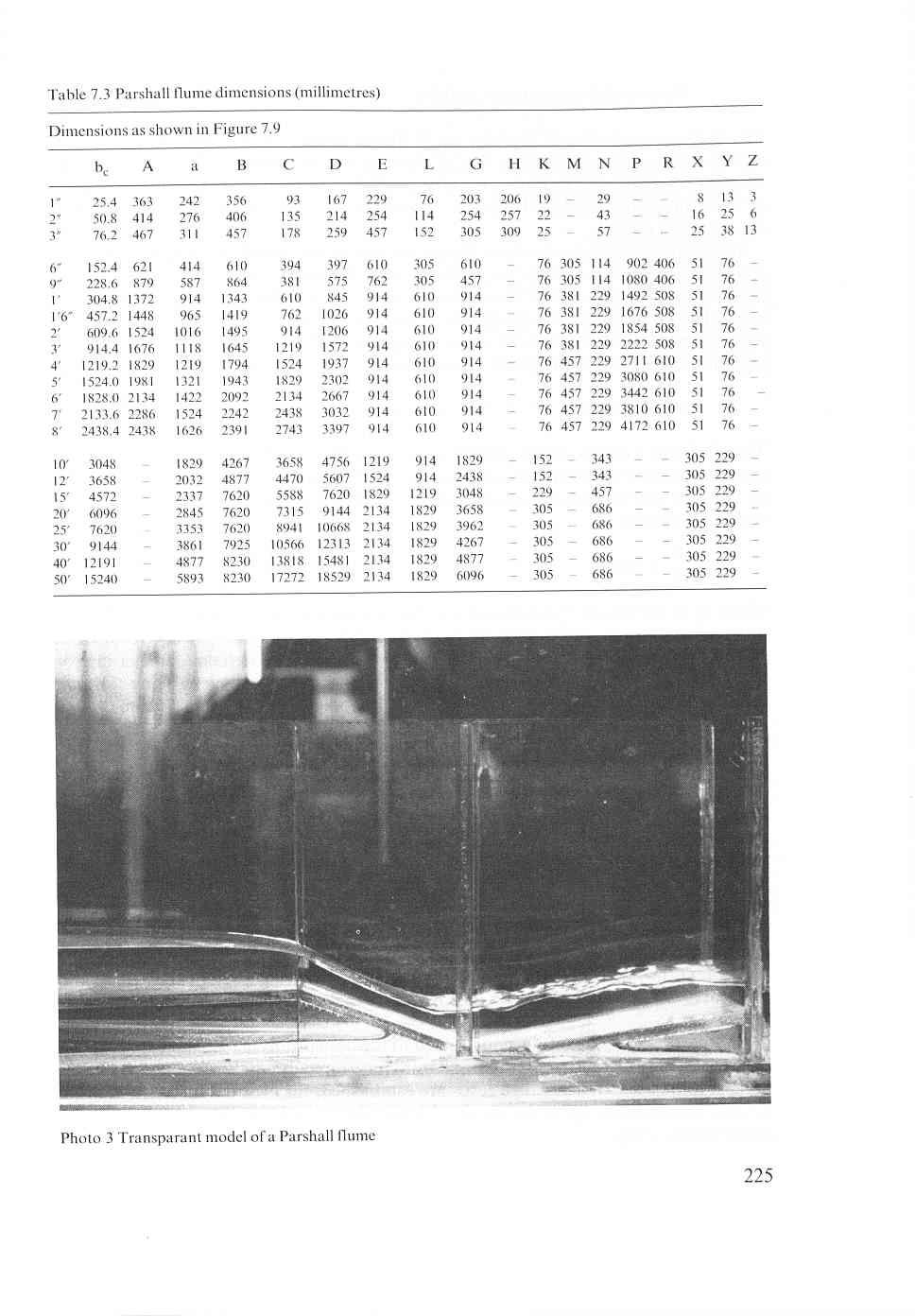
1 measuring ha will be in a zone of flow separation. As already mentioned in Section 7.2.3, the ratios b,/b, and bjl, are also expected to influence the head-discharge relationship. Bennett (1 972) calibrated a number of cutthroat flumes having other overall lengths than m. He reported large scale effects between geometrically identical cutthroat flumes, each of them having sufficiently large dimensions (b, ranged from 0.05 to m). Those scale effects were also mentioned by Eggleston (1967), Skogerboe and Hyatt (1969), and Skogerboe, Bennett, and Walker (1972). In all cases, however, the reported large scale effects are attributed to the improper procedure of comparing measurements with extrapolated relations. As a consequence of the foregoing, no head-discharge relations of cutthroat flumes are given here. Because of their complex hydraulic behaviour, the use of cutthroat flumes is not recommended by the present writers. 7.4 Parshall flumes Description Parshall flumes are calibrated devices for the measurement of water in open channels. They were developed by Parshall (1 922) after whom the device was named. The flume consists of a converging section with a level floor, a throat section with a downward sloping floor, and a diverging section with an upward sloping floor. Because of this unconventional design, the control section of the flume is not situated in the throat but near the end of the level crest in the converging section. The modular limit of the Parshall flume is lower than that of the other long-throated flumes described in Section 7.1. In deviation from the general rule for long-throated flumes where the upstream head must be measured in the approach channel, Parshall flumes are calibrated against a piezometric head, ha, measured at a prescribed location in the converging section. The downstream piezometric head h, is measured in the throat. This typical American practice is also used in the cutthroat and H-flumes. Parshall flumes were developed in various sizes, the dimensions of which are given in Table 7.3. Care must be taken to construct the flumes exactly in accordance with the structural dimensions given for each of the 22 flumes, because the flumes are not hydraulic scale models of each other. Since throat length and throat bottom slope remain constant for series of flumes while other dimensions are varied, each of the 22 flumes is an entirely different device. For example, it cannot be assumed that a dimension in the 12-ft flume will be three times the corresponding dimension in the 4-ft flume. On the basis of throat width, Parshall flumes have been some what arbitrarily classified into three main groups for the convenience of discussing them, selecting sizes, and determining discharges. These groups are very small for 1 -, 2-, and 3-in flumes, small for 6-in through 8-ft flumes and large for IO-ft up to 50-ft flumes (USBR 1971). 224
2
3 Very small flumes (1, 2, and 3 ) The discharge capacity of the very small flumes ranges from 0.09 I/s to 32 I/s. The capacity of each flume overlaps that of the next size by about one-half the discharge range (see Table 7.4). The flumes must be carefully constructed. The exact dimensions of each flume are listed in Table 7.3. The maximum tolerance on the throat width b, equals m. The relatively deep and narrow throat section causes turbulence and makes the h, gauge difficult to read in the very small flumes. Consequently, an h,-gauge, located near the downstream end of the diverging section of the flume is added. Under submerged flow conditions, this gauge may be read instead of the h,-gauge. The h, readings are converted to h, readings by using a graph, as will be explained in Section 7.4.3, and the converted h, readings are then used to determine the discharge. Small flumes (6,9, I, I, 2 up to 8 ) The discharge capacity of the small flumes ranges from m3/s to 3.95 m3/s. The capacity of each size of flume considerably overlaps that of the next size. The length of the side wall of the converging section, A, of the flumes with 1 up to 8 throat width is in metres: b, A = (7-3) where b, is the throat width in metres. The piezometer tap forsthe upstream head, h,, is located in one of the converging walls a distance of a = 3 A upstream from the end of the horizontal crest (see Figure 7.9). The location of the piezometer tap for the downstream head, h,, is the same in all the small flumes, being 51 mm (X = 2 inch) upstream from the low point in the sloping throat floor and 76 mm (Y = 3 inch) above it. The exact dimensions of each size of flume are listed in Table 7.3. Large flumes (1 O up to 50 ) The discharge capacity of the large flumes ranges from O. 16 m3/s to m3/s. The capacity of each size of flume considerably overlaps that of the next size. The axial length of the converging section is considerably longer than it is in the small flumes to obtain an adequately smooth flow pattern in the upstream part of the structure. The measuring station for the upstream head, ha, however, is maintained at a = b,/ m upstream from the end of the horizontal crest. The location of the piezometer tap for the downstream head, h,, is the same in all the large flumes, being 305 mm (12 in) upstream from the floor at the downstream edge of the throat and 229 mm (9 in) above it. The exact dimensions of each size of flume are listed in Table 7.3. All flumes must be carefully constructed to the dimensions listed, and careful levelling is necessary in both longitudinal and transverse directions if the standard discharge table is to be used. When gauge zeros are established, they should be set so that the ha-, hb-, and h,-gauges give the depth of water above the level crest - not the depths above pressure taps. 226
4 surface, S surface FF SECTION A-A converging throat diverging section section section 'I - I III- i-. A Figure 7.9 Parshall flume dimensions If the Parshall flume is never to be operated above the 0.60 submergence limit, there is no need to construct the portion downstream of the throat. The truncated Parshall flume (without diverging section) has the same modular flow characteristics as the standard flume. The truncated flume is sometimes referred to as the 'Montana flume' Evaluation of discharge The upstream head-discharge (ha-q) relationship of Parshall flume of various sizes, as calibrated empirically, is represented by an equation, having the form Q = Kh," (7-4) where K denotes a dimensional factor which is a function of the throat width. The power u varies between and Values of K and u for each size of flume are given in Table 7.4. In the listed equations Q is the modular discharge in m3/s, and ha is the upstream gauge reading in metres. The flumes cover a range of discharges from 0.09 l/s to m3/s and have overlap- 227
5 ping capacities to facilitate the selection of a suitable size. Each of the flumes listed in Table 7.4 is a standard device and has been calibrated for the range of discharges shown in the table. Detailed information on the modular discharge for each size- of flume as a function of h, are presented in the Tables 7.5 to 7.1 I. Table 7.4 Discharge characteristics of Parshall flumes Throat Discharge range Equation Head range Modular width b, in m3/s x IOT3 Q = K hau in metres limit in feet or inches minimum maximum (Q in m3/s) minimum maximum hb/ha 1" 2" 3" 6 9" hal." hal." ha1." ha"" I' 1 ' 6 2' 3' 4' 5' 6' 7' 8' I hal.60' in m3/s 10 12' 15' 20' 25' ' hal hal ha' hal O ,
6 Table 7.5 Free-flow discharge through 1 Parshall measuring flume in I/s computed from the formula Q = hal.55 Head ha (ml,000.o0 I.O02.O03.O04,005,006.O07.O08,009.o I o O O o O O os O I I I I I I I I I Table 7.6 Free-flow discharge through 2 Parshall mesuring flume in l/s computed from the formula Q = Head ha (ml,000.ooi.o02.o03.o04.o05.o06.o07.o08.o09.o 1.o O O o O O7 I.96.O O I I I I I I I I I I I.O I.35 I I I o I I O I I o I I.so I
7 Table 7.7 Free-flow discharge through 3" Parshall measuring flume in I/s computed from the formula Q = ha'.550 Upperhead ha (d.o00.o01.o02.o03.o04.o05.o06.o07.o08.o09.o3.o4.o5.o6.o7.o8.o9.io.i I.12.I3.I I7.I I I I I I I O2 1.o2 1 s o I , O o
8 Table 7.8 Free-flow discharge through 6 Parshall measuring flume in I/s computed from the formula Q = ha'.580 Upperhead ha (m),000.o01,002.o03,004,005,006,007.o08.o09.o3.o4.o5.o6.o7.o8.o9.10.i 1.I2.I3.14.I5.I6.I7.I I I I I I I I 58. I SS.! I I I I
9 Table 7.9 Free-flow discharge through 9 Parshall measuring flume in I/s computed from the formula Q = Upper- head ha ( 4.O00.O0 1.O02.O03,004.O05.O06.O07.O08.O09.O3.O4.o5.O6.O7.O8.O9.IO.II.I2.I3.14.I5.I I so.si I I I I I I
10 Table 7.10 Free-flow discharge through Parshall measuring flumes 1-to-8 foot size in I/s computed from the formulae as shown in Table 7.4 Upper- Discharge in I/s for flumes of various throat widths head ha (") feet feet feet feet feet feet feet feet feet I O I I I , I I02 I04 I06 IO8 I10 I12 I I4 I I I22 I24 I26 I I34 I I40 I I46 I I I I
11 Table 7.10 continued Upper- head ha (" I 8 Discharge in I/s for flumes of various throat widths feet feet feet feet feet feet feet feet feet I66 I68 I70 I I I84 I I I I I I I I I I I I 329. I O I I I I I.o I 560. I
12 Table 7.10 continued Upper- Discharge in l/s for flumes of various throat widths head h, (" feet feet feet feet feet feet feet feet feet I I I I 256. I I I I I I I 897. I I I I048 I069 I090 IIII 1 I33 I I I I98 I220 I242 I I I I I I52 I I I I I I57 I I I I I070 I088 1 IO7 1 I26 I145 I I64 I I84 I I I274 I299 I I506 I532 I559 I I I I I I I 820. I 832. I I I068 I084 I I66 I I83 I I250 I267 I284 I I I342 I I I I508 I I572 I I659 I520 I I I I767 I I I948 I I779 I
13 Table 7.10 continued Upper- Discharge in I/s for flumes of various throat widths head ha (") feet feet feet feet feet feet feet feet feet I I I I007 I I I26 1 I39 1 I I I94 I I249 I I320 I I I I I720 I I703 I725 I748 I I I I I
14 Table 7.1 I Free-flow discharge through Parshall measuring flumes IO to 50 feet size in m3/s. Computed from the formulae as shown in Table 7.4 Upper- Discharge per m3/s for flumes of various throat widths head ha (") feet feet feet feet feet feet feet feet O0 105 I IO I I I50 I55 I I o. I58 O. 173 O I I I.o I.O58 I.O I.266 I I I.65 I.69 o O3 1.O6 1.O I.26 I.29 I.33 I.36 I I I I I I.92 I O4 1.O I I I.90 I I.O I.78 I.83 I I o0 I.o ' I I O3 I.O I I s o 1.57 I.63 I I.90 I o2 1.O I O I I I 237
15 Table 7. I 1 continued Upper- head h, Discharge in m3/s for flumes of various throat widths (" feet feet feet feet feet feet feet feet I I I I I I I
16 Table continued Upper- Discharge in m3/s for flumes of various throat widths head ha (" feet feet feet feet feet feet feet feet O00 I010 I I I Ill I I40 I150 I I60 I I70 I180 I I90 I I230 I I I I I390 I I I I490 I I I I I I I I I I I I I ' I
17 Table 7. I 1 continued Upper- Discharge in m3/s for flumes of various throat widths head ha (") feet feet feet feet feet feet feet feet I I660 I I I 29. I I I I I I I I I I I I I
18 7.4.3 Submerged flow When the ratio of gauge reading h, to ha exceeds the limits of 0.60 for 3-, 6-, and 9-in flumes, 0.70 for 1- to 8-ft flumes and 0.80 for 10- to 50-ft flumes, the modular flume discharge is reduced due to submergence. The non-modular discharge of Parshall flumes equals Qs = Q-QE (7-5) where Q equals the modular discharge (Tables 7.5 to 7.11) and QE is the reduction on the modular discharge due to submergence. The diagrams in Figures 7.10 to 7.16 give the corrections, QE, for submergence for Parshall flumes of various sizes. The correction for the 1-ft flume is made applicable to the 1.5-ft up to 8-ft flumes by multiplying the correction QE for the I-ft flume by the factor given below for the particular size of the flume in use. Size of flume correction b, in ft b,inm factor I S I o 1.4 I Similarly, the correction for the 10-ft flumes is made applicable to the larger flumes by multiplying the correction for the 10-ft flume by the factor given below for the particular flume in use. Size of flume correction b, in ft b,in m factor IO I.o If the size and elevation of the flume cannot be selected to permit modular-flow operation, the submergence ratio h,/h, should be kept below the practical limit of 0.90, 24 1
19 LPSTREAM HEAD ha in metres Figure 7.10 Discharge correction for submerged flow; 1 Parshall flume CORRECTKM 0. in L h Figure 7.1 I Discharge correction for submerged flow; 2 Parshall flume 242
20 UPSTREAM HEAD ho in metres 100.?O.so O7 M.O3.O1 DI O.? ao Figure 7.12 Discharge correction for submerged flow; 3" Parshall flume CORRECTION OE in L/s UPSTREAM HEAD h.in <O0.I O ?O.lo.O7 05.O3 O a o CORRECTION O, in L/s Figure 7.13 Discharge correction for submerged flow; 6 Parshall flume 243
21 UPSTREAM HEAD ha in metres too io.ao.lo 07 B.o3.oa Q. R R W L FLUME.o a ? a i s 7 10 ao io so 70 im CORRECTIOC( 0. in L/S Figure 7.14 Discharge correction for submerged flow; 9 Parshall flume Figure 7.15 Discharge correction for submerged flow; I Parshall flume, correction QE (m3/s) 244
22 CORRECTON in mh Figure 7. I6 Diagram for determining correction to be subtracted from free-discharge flow to obtain submerged flow discharge through 10 Parshall flumes since the flume ceases to be a measuring device if submergence exceeds this limit. It is recommended to use a long-throated flume (Section 7.1) instead of a non-modular Parshall flume. As mentioned, turbulence in the relatively deep and narrow throat of the very small flumes makes the h,-gauge difficult to read. If an h,-gauge is used under submerged flow conditions, the h,-readings should be converted to h,-readings with the aid of Figure 7.17, and the converted h,-values are then used to determine the submerged discharge with the aid of Figures 7.10 to Accuracy of discharge measurement The error in the modular discharge read from the Tables 7.5 to is expected to be about 3%. Under submerged flow conditions the error in the discharge becomes greater, until at 90% submergence the flume ceases to be a measuring device. The method by which this discharge error is to be combined with errors in h,, h,, and the flume dimensions are shown in Annex Loss of head through the flume The size and elevation of the crest of the flume depend on the available loss of head through the flume Ah( N AH). Since for the Parshall flume h, and h, are measured at rather arbitrary locations, the loss of head through the flume Ah is not equal to 245
23 .- o. 3( OX o 10 O O o v HEAO (metres) Figure 7.17 Relationship of h, and hb gauges for I", than 50 percent (after Parshall 1953) 2" and 3" Parshall flumes for submergences greater Figure 7.18 Section of Parshall flume the difference between ha and hb but has a greater value (Figure 7.18). The head loss Ah can be determined from the diagrams in Figures 7.19 and 7.20 for small and large flumes. For very small flumes no data on Ah are available Limits of application The limits of application of the Parshall measuring flumes essential for reasonable accuracy are: a. Each type of flume should be constructed exactly to the dimensions listed in Table, 7.3; 246
24 b. The flume should be carefully levelled in both longitudinal and transverse directions; c. The practical range of heads h, for each type of flume as listed in Table 7.4 is recommended as a limit on h9; d. The submergence ratio h,/h,should not exceed to 8' F SH4LL FL PERCENTAGE OF SUBMERGEN( 4EAD LOSS C AH THROUGH FLUME in metres L 0.10 o O Figure 7.19 Head-loss through Parshall flumes. I' up to 8' Parshall flumes 247
STEALTH INTERNATIONAL INC. DESIGN REPORT #1001 IBC ENERGY DISSIPATING VALVE FLOW TESTING OF 12 VALVE
 STEALTH INTERNATIONAL INC. DESIGN REPORT #1001 IBC ENERGY DISSIPATING VALVE FLOW TESTING OF 12 VALVE 2 This report will discuss the results obtained from flow testing of a 12 IBC valve at Alden Research
(Refer Slide Time: 00:01:10min)
") Introduction to Transportation Engineering Dr. Bhargab Maitra Department of Civil Engineering Indian Institute of Technology, Kharagpur Lecture - 11 Overtaking, Intermediate and Headlight Sight Distances
Introduction to Transportation Engineering Dr. Bhargab Maitra Department of Civil Engineering Indian Institute of Technology, Kharagpur Lecture - 11 Overtaking, Intermediate and Headlight Sight Distances
The Discussion of this exercise covers the following points:
 Exercise 3-3 Venturi Tubes EXERCISE OBJECTIVE In this exercise, you will study the relationship between the flow rate and the pressure drop produced by a venturi tube. You will describe the behavior of
HEATEC TEC-NOTE. Portable fuel tanks. Volumes and Levels. Publication No Revised FIGURE 2. VOLUMES* (GALLONS)
") HEATEC TEC-NOTE SCOPE This document applies to portable fuel tanks currently manufactured by Heatec (Figure 1). It defines different types of tank volumes and enables users to convert levels to volume.
HEATEC TEC-NOTE SCOPE This document applies to portable fuel tanks currently manufactured by Heatec (Figure 1). It defines different types of tank volumes and enables users to convert levels to volume.
Components of Hydronic Systems
 Valve and Actuator Manual 977 Hydronic System Basics Section Engineering Bulletin H111 Issue Date 0789 Components of Hydronic Systems The performance of a hydronic system depends upon many factors. Because
Exercise 4-1. Flowmeters EXERCISE OBJECTIVE DISCUSSION OUTLINE DISCUSSION. Rotameters. How do rotameter tubes work?
 Exercise 4-1 Flowmeters EXERCISE OBJECTIVE Learn the basics of differential pressure flowmeters via the use of a Venturi tube and learn how to safely connect (and disconnect) a differential pressure flowmeter
Chapter III Geometric design of Highways. Tewodros N.
 Chapter III Geometric design of Highways Tewodros N. www.tnigatu.wordpress.com tedynihe@gmail.com Introduction Appropriate Geometric Standards Design Controls and Criteria Design Class Sight Distance Design
CSO/STORMWATER MANAGEMENT. HYDROVEX FluidHook Control Gate Valve
 CSO/STORMWATER MANAGEMENT HYDROVEX FluidHook Control Gate Valve HYDROVEX FLUIDHOOK CONTROL GATE VALVE APPLICATION The flow regulation at storm overflows or retention facilities is usually performed with
CHECK AND CALIBRATION PROCEDURES FOR FATIGUE TEST BENCHES OF WHEEL
 STANDARDS October 2017 CHECK AND CALIBRATION PROCEDURES FOR FATIGUE TEST BENCHES OF WHEEL E S 3.29 Page 1/13 PROCÉDURES DE CONTRÔLE ET CALIBRAGE DE FATIGUE BANCS D'ESSAIS DE ROUE PRÜFUNG UND KALIBRIERUNG
VERIFYING THE ACCURACY OF LIQUID ADDITIVE METERING SYSTEMS
 Test Procedure for VERIFYING THE ACCURACY OF LIQUID ADDITIVE METERING SYSTEMS Texas Department of Transportation TxDOT Designation: Tex-923-K Effective Date: August 1999 1. SCOPE 1.1 Use this method to
3.2. Current Limiting Fuses. Contents
 .2 Contents Description Current Limiting Applications................. Voltage Rating.......................... Interrupting Rating....................... Continuous Current Rating................ Fuse
EXTRACT of chapter XXXIV coupling devices (version of ) ANNEX XXXIV Requirements on mechanical couplings
 ANNEX XXXIV Requirements on mechanical couplings") EXTRACT of chapter XXXIV coupling devices (version of 18.09.2013) ANNEX XXXIV Requirements on mechanical couplings Definitions specific to this Annex Mechanical coupling between tractor and towed vehicle
EXTRACT of chapter XXXIV coupling devices (version of 18.09.2013) ANNEX XXXIV Requirements on mechanical couplings Definitions specific to this Annex Mechanical coupling between tractor and towed vehicle
Piping Design. From the METTLER TOLEDO Weigh Module Systems Handbook
 Piping Design Any time that piping is connected to a tank scale (a dead-to-live connection), there is a potential for mechanical binding. If piping is not installed properly, it can cause weighing errors
A Generalised Approach In Identifying Control Link Tolerances And Its Effect On Design Tolerances Of Mechanism Using Instantaneous Center
 A Generalised Approach In Identifying Control Link Tolerances And Its Effect On Design Tolerances Of Mechanism Using Instantaneous Center C. C. Handa and H. T. Thorat 1 KDK College of Engineering 1 Visveshvarya
Tension Control Inverter
 Tension Control Inverter MD330 User Manual V0.0 Contents Chapter 1 Overview...1 Chapter 2 Tension Control Principles...2 2.1 Schematic diagram for typical curling tension control...2 2.2 Tension control
Module 6. Actuators. Version 2 EE IIT, Kharagpur 1
 Module 6 Actuators Version 2 EE IIT, Kharagpur 1 Lesson 25 Control Valves Version 2 EE IIT, Kharagpur 2 Instructional Objectives At the end of this lesson, the student should be able to: Explain the basic
FLOW NOZZLES - 3 SAMIL INDUSTRY CO.,LTD. IN THIS CHAPTER - 3
 - 3 IN THIS CHAPTER - 3 Here is introduce the measuring primary devices of fluid flow by means of the differential pressure that is flow nozzles to use at high pressure and temperature than the orifice
CHAPTER 4 : RESISTANCE TO PROGRESS OF A VEHICLE - MEASUREMENT METHOD ON THE ROAD - SIMULATION ON A CHASSIS DYNAMOMETER
 CHAPTER 4 : RESISTANCE TO PROGRESS OF A VEHICLE - MEASUREMENT METHOD ON THE ROAD - SIMULATION ON A CHASSIS DYNAMOMETER 1. Scope : This Chapter describes the methods to measure the resistance to the progress
Tilting Flow Channel, 300mm wide
 OSC 77FD530HF Tilting Flow Channel, 300mm wide -The channel is designed for studying the hydraulic flow phenomena Under Frame -The channel bed is an invert which rests on an H-beam under frame
INTRODUCTION Measuring the flow of liquids is a critical need in many industrial plants. In some operations, the ability to conduct accurate flow
 Flow INTRODUCTION Measuring the flow of liquids is a critical need in many industrial plants. In some operations, the ability to conduct accurate flow measurements is so important that it can make the
CLEARLINE PROFILER REPORT P.R. Anderson CleanFlow Systems Limited, Albany, Auckland, New Zealand
 CLEARLINE PROFILER REPORT P.R. Anderson CleanFlow Systems Limited, Albany, Auckland, New Zealand Location: Chullora, Sydney Australia Pipe Size: 1225 Age of Pipe: 1890 s Pipe Type: CICL (Cast-iron) Pipe
V-Notch Weir User Manual
 V-Notch Weir User Manual Man152 2.1.0 04/08/2014 C.Spalton Andy Small Chris Rasmussen Manual No. Revision Date Originator Checked Authorised for Issue User Manual 1 Contents Section 2 : Introduction...
Measurement of thermocouple emf using potentiometer & milivoltmeter. Milivoltmeter consists of a PMMC type meter. The coil gets magnetised when the
 Measurement of thermocouple emf using potentiometer & milivoltmeter. Milivoltmeter consists of a PMMC type meter. The coil gets magnetised when the voltage is applied across the coil. The coil rotates
Experiment (4): Flow measurement
: Flow measurement") Introduction: The flow measuring apparatus is used to familiarize the students with typical methods of flow measurement of an incompressible fluid and, at the same time demonstrate applications of the
Introduction: The flow measuring apparatus is used to familiarize the students with typical methods of flow measurement of an incompressible fluid and, at the same time demonstrate applications of the
LESSON Transmission of Power Introduction
 LESSON 3 3.0 Transmission of Power 3.0.1 Introduction Earlier in our previous course units in Agricultural and Biosystems Engineering, we introduced ourselves to the concept of support and process systems
2014 Gag Update Summary
 2014 Gag Update Summary The SEDAR 10 gag assessment was updated in 2014 with data through 2012. The methodologies and historical data between the two assessments remained mostly consistent, with a few
Hydraulic Design of Navigation Locks
 Hydraulic Design of Navigation Locks U.S. Army Corps of Engineers Navigation Systems Research Program U.S. Army Engineer Research & Development Center Coastal and Hydraulics Laboratory Navigation Branch
EQUAL DISTRIBUTION OF WASTEWATER USING LOW-PRESSURE DISTRIBUTION Larry D. Stephens, P.E. *
 EQUAL DISTRIBUTION OF WASTEWATER USING LOW-PRESSURE DISTRIBUTION Larry D. Stephens, P.E. * INTRODUCTION Experience with onsite systems has proven that equal application of wastewater over the entire soil
The Discussion of this exercise covers the following points:
 Exercise 1 Battery Fundamentals EXERCISE OBJECTIVE When you have completed this exercise, you will be familiar with various types of lead-acid batteries and their features. DISCUSSION OUTLINE The Discussion
Hydraulics Guide. Table 1: Conveyance Factors (English Units)... 7 Table 2: Conveyance Factors (Metric Units)... 8
... 7 Table 2: Conveyance Factors (Metric Units)... 8") Table of Contents 1.1 Index of Tables... 1 1.2 Index of Figures... 1 1.3 Overview of Hydraulic Considerations... 2 1.4 Discharge Curves... 2 1.5 Conveyance Method... 5 1.6 Flow Velocity Considerations...
Table of Contents 1.1 Index of Tables... 1 1.2 Index of Figures... 1 1.3 Overview of Hydraulic Considerations... 2 1.4 Discharge Curves... 2 1.5 Conveyance Method... 5 1.6 Flow Velocity Considerations...
Common position by FR and CEMA on mechanical couplings for towed vehicles 28/9/2015
 Common position by FR and CEMA on mechanical couplings for towed vehicles 28/9/2015 ANNEX XXXIV Requirements on mechanical couplings 1. Definitions For the purposes of this Annex: 1.1. Mechanical coupling
ABSTRACT INTRODUCTION
 Wind tunnel investigation of waste air re-entry with wall ventilation P. Broas Technical Research Centre of Finland, Ship Laboratory, Tekniikantie 12, SF-02150, Espoo, Finland ABSTRACT A wind tunnel investigation
MULTICHANNEL ULTRASONIC FLOW METER AFLOWT UF
 MULTICHANNEL ULTRASONIC FLOW METER AFLOWT UF VERSION UF-5xx d INSTALLATION MANUAL ISO 9001:2008 CONTENTS Page INTRODUCTION... 3 1. SAFETY INSTRUCTIONS... 4 2. MOUNTING PREPARATION... 4 3. MOUNTING REQUIREMENTS...
STAINLESS STEEL PRESSURE REDUCING VALVE PRV ELITE
 Pressure (bar) STAINLESS STEEL PRESSURE REDUCING VALVE PRV ELITE MAIN CHARACTERISTICS The stainless steel PRV elite valve is intended for the function of pressure reduction of the fluids such as water,
CHAPTER 6 MECHANICAL SHOCK TESTS ON DIP-PCB ASSEMBLY
 135 CHAPTER 6 MECHANICAL SHOCK TESTS ON DIP-PCB ASSEMBLY 6.1 INTRODUCTION Shock is often defined as a rapid transfer of energy to a mechanical system, which results in a significant increase in the stress,
IMPACT REGISTER, INC. PRECISION BUILT RECORDERS SINCE 1914
 IMPACT REGISTER, INC. PRECISION BUILT RECORDERS SINCE 1914 RM-3WE (THREE WAY) ACCELEROMETER GENERAL The RM-3WE accelerometer measures and permanently records, for periods of 30, 60, and 90 days, the magnitude,
Technical Information Average Efficiency of the SMA Flexible Storage System
 Technical Information Average Efficiency of the SMA Flexible Storage System The average efficiency of a system for intermediate storage of energy, e.g. of the SMA Flexible Storage System, indicates how
A Short Method For Calculating Outage For Loading of Molasses Tank Cars
 A Short Method For Calculating Outage For Loading of Molasses Tank Cars H. M. BAUSERMAX' It is required by railroad companies thai, molasses cars set for loading shall be loaded within certain limits of
EL Beam Sensors Standard & SC Versions
 EL Beam Sensors Standard & SC Versions 56801399 Copyright 2008 Slope Indicator Company. All Rights Reserved. This equipment should be installed, maintained, and operated by technically qualified personnel.
Permanent Multipath Clamp-On Transit Time Flow Meter
 Permanent Multipath Clamp-On Transit Time Flow Meter By: Dr. J. Skripalle HydroVision GmbH, Germany Introduction For many years now, ultrasonic flow measurements with wetted sensors have been a well established
Original. M. Pang-Ngam 1, N. Soponpongpipat 1. Keywords: Optimum pipe diameter, Total cost, Engineering economic
 Original On the Optimum Pipe Diameter of Water Pumping System by Using Engineering Economic Approach in Case of Being the Installer for Consuming Water M. Pang-Ngam 1, N. Soponpongpipat 1 Abstract The
EMCO Primary Elements for Flow Measurement
 EMCO Primary Elements for Flow Measurement Introduction EMCO primary elements measure the flow of liquids, gases and steam according to the differential pressure principle. The primary elements are widely
SURFACE VEHICLE STANDARD
 400 Commonwealth Drive, Warrendale, PA 15096-0001 SURFACE VEHICLE STANDARD J1287 Issued 1980-06 Reaffirmed 1998-07 REAF. JUL1998 An American National Standard Superseding J1287 JUN93 Measurement of Exhaust
Ohio State University Extension. Boom Sprayer Calibration, AEX Food, Agricultural and Biological Engineering
 Page 1 of 7 Ohio State University Extension Food, Agricultural and Biological Engineering 590 Woody Hayes Dr., Columbus, Ohio 43210 Boom Sprayer Calibration AEX-520-92 H. Erdal Ozkan Professor and Extension
8.2 ROUTE CHOICE BEHAVIOUR:
 8.2 ROUTE CHOICE BEHAVIOUR: The most fundamental element of any traffic assignment is to select a criterion which explains the choice by driver of one route between an origin-destination pair from among
DN 15 to DN100 Between flanges PN10/16/25/40 and Class C C
 MADE OF STAINLESS... Size : Ends : Min Temperature : Max Temperature : Max Pressure : 40 Bars Specifications : Spring type All positions Metal / metal DN 15 to DN100 Between flanges PN10/16/25/40 and Class
Installation Procedures
 For the precision ball and roller bearings supplied by MRC Bearings, skill and cleanliness while handling, mounting and dismounting are necessary to ensure satisfactory bearing performance. As precision
Laboratory Exercise 12 THERMAL EFFICIENCY
 Laboratory Exercise 12 THERMAL EFFICIENCY In part A of this experiment you will be calculating the actual efficiency of an engine and comparing the values to the Carnot efficiency (the maximum efficiency
testing and measuring instruments for vehicle wheels
 testing and measuring instruments for vehicle wheels en testing and measuring instruments for vehicle wheels For more than 20 years MAKRA has been manufacturing measuring and testing equipment for the
Programming of different charge methods with the BaSyTec Battery Test System
 Programming of different charge methods with the BaSyTec Battery Test System Important Note: You have to use the basytec software version 4.0.6.0 or later in the ethernet operation mode if you use the
YARWAY NARVIK MODEL 88 SPID SMALL PIPE INLINE DESUPERHEATER
 A wide range of desuperheaters, pneumatic actuators, strainers to satisfy all specifications of the power, pulp and paper industry and process gas applications FEATURES Fabricated construction Special
Sleeve Valves Energy Dissipaters
 Sleeve Valves Energy Dissipaters Engineering Creative Solutions for Fluid Systems Since 1901 A Tradition of Excellence With the development of the first rubber seated butterfly valve more than 70 years
Strip Width Gauge Operating and Service Instructions
 Strip Width Gauge VABM 4-00 Operating and Service Instructions erstellt am 25.2.2002 freigegeben am Bemerkungen Rev.01 Seiten: Name: Rietdorf Name: Name: measuring - controlling - recording - automation
Materials : Stainless steel ASTM A351 CF8M
 Certificate 3.1 Size : Ends : Min Temperature : Max Temperature : Max Pressure : 40 Bars Specifications : Spring type All positions Metal / metal DN 15 to DN200 Between flanges PN10/16/25/40 and Class
Rosemex Products 96 VENTILATION INDUCTION UNIT
 10 Rosemex Products 96 VENTILATION INDUCTION UNIT 1 INDEX Unit features... 1-4 Nomenclature... 5 System comments... 5 Selection procedures... 5-6 Vertical selection tables... 7-12 Low Vertical selection
Pembina Emerson Border Crossing Interim Measures Microsimulation
 Pembina Emerson Border Crossing Interim Measures Microsimulation Final Report December 2013 Prepared for: North Dakota Department of Transportation Prepared by: Advanced Traffic Analysis Center Upper Great
TRANSMITTER ATTACHES TO THIS SURFACE
 FIELD DEVICES - PRESSURE Product Specifications Logo PSS 3-5A1 B Model IFOA Integral Flow Orifice Assembly Used with I/A Series or Pneumatic d/p Cell Transmitters PNEUMATIC TRANSMITTER TRANSMITTER ATTACHES
Types and 52.20, Specialized test procedure Milk receiving and milk pick-up metering systems
 Types 52.10 and 52.20, Specialized test procedure Milk receiving and milk pick-up metering systems Category: Volume Part: 4-STP Section: 28 Publication date: 2017-06-08 Revision number: 4 Application Milk
Fisher 4194S Differential Pressure Controllers
 Instruction Manual 4194S Controllers Fisher 4194S Differential Pressure Controllers Contents 1. Introduction... 2 Scope of Manual... 2 Description... 2 Specifications... 5 Educational Services... 5 2.
Title: Terms and Conditions for the Approval of Coriolis Liquid Meters. Effective Date: Page: 1 of 9 Revision: 1
 Effective Date: 2012-12-01 Page: 1 of 9 Revision: 1 1.0 Application These terms and conditions apply to Coriolis metering assemblies and to metering installations used in trade 1. 2.0 Definitions In this
TX101/201 Insertion Turbine Instructions
 TX101/201 Insertion Turbine Instructions General Information Ruby bearings and a non-drag pick-off give these adjustable insertion turbine flow sensors a wide flow and long life. A sensor detects the passage
20th. SOLUTIONS for FLUID MOVEMENT, MEASUREMENT & CONTAINMENT. Do You Need a Booster Pump? Is Repeatability or Accuracy More Important?
 Do You Need a Booster Pump? Secrets to Flowmeter Selection Success Is Repeatability or Accuracy More Important? 20th 1995-2015 SOLUTIONS for FLUID MOVEMENT, MEASUREMENT & CONTAINMENT Special Section Inside!
CSO/STORMWATER MANAGEMENT. HYDROVEX CCV Check Valve
 CSO/STORMWATER MANAGEMENT HYDROVEX CCV Check Valve HYDROVEX CCV CIRCULAR CHECK VALVE APPLICATION The HYDROVEX CCV Check Valve is designed for use in water and sewage. It has no reinforcement and is especially
SECTION 9 STORM SEWER INLETS
 SECTION 9 STORM SEWER INLETS CITY OF WESTMINSTER STORM DRAINAGE DESIGN AND TECHNICAL CRITERIA SECTION 9 STORM SEWER INLETS 9.1 INTRODUCTION There are three types of inlets: curb opening, grated, and combination
Instruction Manual. Vibration Calibrator VC20. Manfred Weber. Metra Mess- und Frequenztechnik in Radebeul e.k. Meissner Str D Radebeul
 Instruction Manual Vibration Calibrator VC20 Manfred Weber Metra Mess- und Frequenztechnik in Radebeul e.k. Meissner Str. 58 - D-01445 Radebeul Tel. +49-351 836 2191 Fax +49-351 836 2940 Email: Info@MMF.de
GEOMETRIC ALIGNMENT AND DESIGN
 GEOMETRIC ALIGNMENT AND DESIGN Geometric parameters dependent on design speed For given design speeds, designers aim to achieve at least the desirable minimum values for stopping sight distance, horizontal
MAGNETIC FORCE ON A CURRENT-CARRYING WIRE
 MAGNETIC FORCE ON A CURRENT-CARRYING WIRE Pre-Lab Questions Page 1. What is the SI unit for Magnetic Field? Name: Class: Roster Number: Instructor: 2. The magnetic field on a wire is 12.0 x 10 5 Gausses,
E.P. (Extreme Pressure) & LUBRICITY TESTER OFI Part No
 & LUBRICITY TESTER OFI Part No") OFI Testing Equipment E.P. & Lubricity Tester Instructions Part # 111-00 Page 1 of 8 E.P. (Extreme Pressure) & LUBRICITY TESTER OFI Part No. 111-00 The OFI combination EP and Lubricity Tester is a high-quality
OFI Testing Equipment E.P. & Lubricity Tester Instructions Part # 111-00 Page 1 of 8 E.P. (Extreme Pressure) & LUBRICITY TESTER OFI Part No. 111-00 The OFI combination EP and Lubricity Tester is a high-quality
Selective Coordination Enforcement:
 Selective Coordination Enforcement: Overcurrent Protective Device Basics by Tim Crnko The Basics of Selective Coordination Merely having a higher ampere overcurrent protective device (OCPD) feeding a lower
Fisher 4194HS Differential Pressure Indicating Controllers
 Instruction Manual Fisher 4194HS Differential Pressure Indicating Controllers Contents Introduction... 2 Scope of Manual... 2 Description... 2 Specifications... 5 Educational Services... 5 Installation,
Determination of power loss of combine harvester travel gear
 Agronomy Research 13(1), 5 3, 015 Determination of power loss of combine harvester travel gear L. Beneš *, P. Heřmánek and P. Novák Czech University of Life Sciences Prague, Faculty of Engineering, Department
MOTOR SAMPLE PROBLEM #1 Low-Slip Drive Belts
 MOTOR SAMPLE PROBLEM #1 Low-Slip Drive Belts Low-slip drive belts have been recommended to the owner of Grapes dù Räth as a way to reduce the energy consumption of his wine cellar ventilation system. If
KISSsoft 03/2017 Tutorial 15
 KISSsoft 03/2017 Tutorial 15 Bevel gears KISSsoft AG Rosengartenstrasse 4 8608 Bubikon Switzerland Tel: +41 55 254 20 50 Fax: +41 55 254 20 51 info@kisssoft.ag www.kisssoft.ag Contents 1 Starting KISSsoft...
B G SPIRAL BEVEL GEARBOXES BG SPIRAL BEVEL GEARBOXES
 BG 1 SPECIFICATION GENERAL Spiral bevel gearboxes BG incorporate the most modern advances in bevel gearbox design and construction. These gearboxes offer an extensive range of ratios together with an excellent
M-11 MARINE DIESEL ENGINE FUEL INJECTOR
 Guideline No.M-11(201510) M-11 MARINE DIESEL ENGINE FUEL INJECTOR Issued date: 20 October 2015 China Classification Society Foreword This Guideline constitutes the CCS rules, and establishes the applicable
SHAFT ALIGNMENT FORWARD
 Service Application Manual SAM Chapter 630-76 Section 24 SHAFT ALIGNMENT FORWARD One of the basic problems of any installation is aligning couplings or shafts. Therefore, this section will endeavor to
FLOW RATE STATIC BALANCING Valves for radiators
 Balancing part 3 TECHNICAL FOCUS FLOW RATE STATIC BALANCING Valves for radiators The valves for radiators equipped with pre-setting device play a very important role in balancing the heating systems circuits.
AN OPTIMAL PROFILE AND LEAD MODIFICATION IN CYLINDRICAL GEAR TOOTH BY REDUCING THE LOAD DISTRIBUTION FACTOR
 AN OPTIMAL PROFILE AND LEAD MODIFICATION IN CYLINDRICAL GEAR TOOTH BY REDUCING THE LOAD DISTRIBUTION FACTOR Balasubramanian Narayanan Department of Production Engineering, Sathyabama University, Chennai,
Dynamics of Machines. Prof. Amitabha Ghosh. Department of Mechanical Engineering. Indian Institute of Technology, Kanpur. Module No.
 Dynamics of Machines Prof. Amitabha Ghosh Department of Mechanical Engineering Indian Institute of Technology, Kanpur Module No. # 04 Lecture No. # 03 In-Line Engine Balancing In the last session, you
DIY balancing. Tony Foale 2008
 DIY balancing. Tony Foale 2008 I hope that the main articles on the theory behind engine balance have removed the mystic which often surrounds this subject. In fact there is no reason why anyone, with
Driver Card. ZPA Hybrid driver card. Standard Accessories. Option. Built-in *ZPA logic for avoiding collisions between transferred loads
 Driver Card ZPA Hybrid driver card Conformity Conformity Applicable MDR models Driver model CAUTION tandard Accessories Option Built-in *ZPA logic for avoiding collisions between transferred loads Multiple
SCHMIDT ManualPress 300 Series Manual Presses with Process Monitoring
 Manual Presses with Process Monitoring Process reliability, force/stroke monitoring of the joining process and EN ISO-compatible documentation of the results are becoming the major factors for small and
CENTRIFUGAL PUMP: Parallel and Series Operation 11/11/02
 CENTRIFUGAL PUMP: Parallel and Series Operation 11/11/02 1 CENTRIFUGAL PUMP Location Sub-basement SB-92. (Manual is available) Introduction This experiment illustrates the basic operation and characteristics
FEASIBILITY STYDY OF CHAIN DRIVE IN WATER HYDRAULIC ROTARY JOINT
 FEASIBILITY STYDY OF CHAIN DRIVE IN WATER HYDRAULIC ROTARY JOINT Antti MAKELA, Jouni MATTILA, Mikko SIUKO, Matti VILENIUS Institute of Hydraulics and Automation, Tampere University of Technology P.O.Box
Study of intake manifold for Universiti Malaysia Perlis automotive racing team formula student race car
 Journal of Physics: Conference Series PAPER OPEN ACCESS Study of intake manifold for Universiti Malaysia Perlis automotive racing team formula student race car To cite this article: A Norizan et al 2017
Electromagnetic clutch-brake combinations INTORQ
 Electromagnetic clutch-brake combinations INTORQ 14.800 14.867 7.5 120 Nm setting the standard 2 CBC en 5/2005 Contents Clutch-brake combinations Product information 4 Type code 6 Design selection 8 Overview
SUMMARY. St-jean-sur-Richelieu, 2016, January 12th Client : J.A. Roby Project :PI model : Polaris; Sirius; Véga; Antares; Centauri; Rigel
 SUMMARY St-jean-sur-Richelieu, 2016, January 12th 1 Introduction... 4 1.1 General... 4 1.2 Test unit information... 4 1.3 Results... 4 1.4 Pretest information... 5 2 Summary of test results... 5 2.1 Emissions...
BS EN :2006. Hot finished structural hollow sections of non alloy and fine grain steels
 . BS EN 1010 :006 Hot finished structural hollow sections of non alloy and fine grain steels 1 Scope This part of EN 1010 specifies tolerances for hot finished circular, square, rectangular and elliptical
EZS. Motorized Linear Slides. Series. RoHS-Compliant
 RoHS-Compliant Motorized Linear Slides EZS Series AUDIN -, avenue de la malle - 5137 Saint Brice Courcelles - Tel : 3...1 - Fax : 3... - Web : http: www.audin.fr - Email : info@audin.fr RoHS-Compliant
ULTRASONIC FLOW SENSOR IFX-M4-01
 ULTRASONIC FLOW SENSOR IFX-M4-01 TECHNICAL DESCRIPTION, OPERATING INSTRUCTION IFX-M4-01 2012-09-10 TABLE OF CONTENTS 1. APPLICATION... 3 2. TECHNICAL DATA... 4 3. PACKAGE CONTENT... 6 4. OPERATING PRINCIPLE...
series Silencers
 series SK Silencers www.koolair.com Series SK 1 Silencers CONTENTS ASK-1 and ASK-2 Round Silencers Description 4 ASK-1 Overall Dimensions 5 ASK-2 Overall Dimensions 6 Selection Table and Weights 7 ASK-1
FLUID FLOW. Introduction
 FLUID FLOW Introduction Fluid flow is an important part of many processes, including transporting materials from one point to another, mixing of materials, and chemical reactions. In this experiment, you
Q1. Figure 1 shows a straight wire passing through a piece of card.
 THE MOTOR EFFECT Q1. Figure 1 shows a straight wire passing through a piece of card. A current (I) is passing down through the wire. Figure 1 (a) Describe how you could show that a magnetic field has been
Seals Stretch Running Friction Friction Break-Out Friction. Build With The Best!
 squeeze, min. = 0.0035 with adverse tolerance build-up. If the O-ring is made in a compound that will shrink in the fluid, the minimum possible squeeze under adverse conditions then must be at least.076
FLOW AND HEAT TRANSFER ENHANCEMENT AROUND STAGGERED TUBES USING RECTANGULAR VORTEX GENERATORS
 FLOW AND HEAT TRANSFER ENHANCEMENT AROUND STAGGERED TUBES USING RECTANGULAR VORTEX GENERATORS Prabowo, Melvin Emil S., Nanang R. and Rizki Anggiansyah Department of Mechanical Engineering, ITS Surabaya,
} Rev.1/Add.12/Rev.6/Amend.4
 30 December 2009 AGREEMENT CONCERNING THE ADOPTION OF UNIFORM TECHNICAL PRESCRIPTIONSFOR WHEELED VEHICLES, EQUIPMENT AND PARTS WHICH CAN BE FITTEDAND/OR BE USED ON WHEELED VEHICLES AND THE CONDITIONS FOR
Calculating AC Line Voltage Drop for M215 Microinverters with Engage Cables
 Technical Brief Calculating AC Line Voltage Drop for M215 Microinverters with Engage Cables Contents Overview... 1 Voltage Rise for M215s with the 240 VAC Engage Cable... 2 Voltage Rise for M215s with
Busy Ant Maths and the Scottish Curriculum for Excellence Year 6: Primary 7
 Busy Ant Maths and the Scottish Curriculum for Excellence Year 6: Primary 7 Number, money and measure Estimation and rounding Number and number processes Including addition, subtraction, multiplication
CALIBRATION LEARNING OBJECTIVES
 C H A P TE R 4 CALIBRATION LEARNING OBJECTIVES After completely studying this chapter, you should: Understand the purpose of calibration and why it is an essential process. Know the basic tools needed
Motor Vehicles Working Group (MVWG)
") EUROPEAN COMMISSION ENTERPRISE DIRECTORATE-GENERAL Single market, regulatory environment, industries under vertical legislation Automotive industry Motor Vehicles Working Group (MVWG) Brussels, 27 October
EUROPEAN COMMISSION ENTERPRISE DIRECTORATE-GENERAL Single market, regulatory environment, industries under vertical legislation Automotive industry Motor Vehicles Working Group (MVWG) Brussels, 27 October