Hydraulic Design of Navigation Locks
|
|
|
- Zoe Griffith
- 6 years ago
- Views:
Transcription


1 Hydraulic Design of Navigation Locks U.S. Army Corps of Engineers Navigation Systems Research Program U.S. Army Engineer Research & Development Center Coastal and Hydraulics Laboratory Navigation Branch Richard Stockstill US Army Corps of Engineers


2 Tows Setting Up for Lock Operation Check Posts Line Hooks Floating Mooring Bitts 2
3 USACE Lock Design Guidance Hydraulic Design EM Hydraulic Design of Navigation Locks EM Hydraulic Design of Lock Culvert Valves Planning EM Planning and Design of Navigation Locks General Discussion Davis, J. P Hydraulic Design of Navigation Locks MP HL- 89-5, Vicksburg, MS: U.S. Army Engineer Waterways Experiment Station 3
4 TRANSIT TIME 7 different components: 1. Time required for a tow to move from an arrival point to the lock chamber 2. Time to enter the lock chamber 3. Time to close the gates 4. Time to raise or lower the lock surface (fill or empty) 5. Time to open the gates 6. Time for the tow to exit from the chamber 7. Time required for the tow to reach a clearance point so that another tow moving in the opposite direction can start toward the lock 4

5 Lock Sizes 5
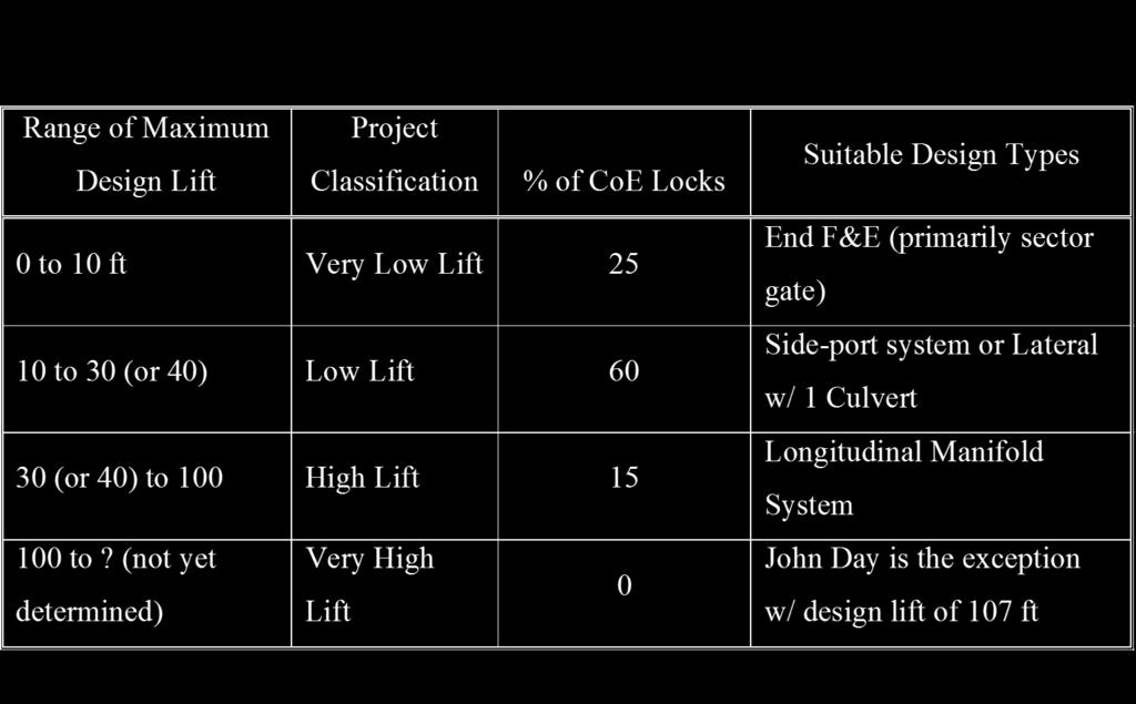
6 Classification by Lift 6
7 End Filling System, Sector Gates 7

8 Sidewall Port System 8
9 9
10 Sidewall Port System Most widely used (in US) for locks up to 1200 by 110 with lift up to about 30 Features Multiport intakes Ports in each wall are staggered Reverse tainter valves Problem: flow from upstream ports occurs first Section View of Sidewall Port System 10

11 Surface Velocities during Lock Filling, Jets Issuing from Sidewall Manifolds 11
12 Interlaced Lateral System 12
13 Split Lateral System 13

14 Single H System Whitten Lock Tennessee-Tombigbee Waterway 14
15 Single H System Whitten Lock 15
16 Double H System 16
17 In-Chamber Longitudinal Culvert System (ILCS) 17
18 ILCS Design Philosophy Develop a system nearly as efficient as the sideport filling and emptying system Culverts in the chamber walls are replaced by culverts in the chamber floor Marmet Lock 18
 Marmet McAlpine")
19 In-chamber Longitudinal Culvert System (ILCS) Marmet McAlpine 19


20 Features of Locks Guide Walls essentially continuations of a lock wall- placed at each end to aid towboat pilot in aligning the tow for entry into the lock chamber used to guide tow into chamber. Guard Walls placed at each end of a lock on the opposite side from the guide walls When 2 parallel locks are built adjacent to spillway, a guard wall may be long or longer than a guide wall Serves as a guard between the navigation channel and the spillway 20
21 Features of Locks Lock Sills structure on the bottom across the lock that the gates contact when they are closed. Sill elevation affects the transit time Downbound Tow Leaving Lock Chamber Upbound Tow Entering Lock Chamber 21
22 Features of Locks Lock Gates Miter Gate Do not operate under head and can not withstand very much reverse head 22
23 Submergible Vertical-Lift Gate fit nicely in high-head locks where the recess can be in the upper sill Overhead Vertical-Lift Gate used at the downstream gate at high-head projects less maintenance than submergible gates Submergible tainter gate Lock Gates Vertical axis sector gate like miter gate, these have 2 gates at each end of the chamber somewhat like tainter gates mounted on vertical axis They are used as end filling in very low lift locks Can be designed to withstand head from either side so they are ideal for tidal situations that result in reverse head 23
24 Lock Gates Rolling gate rolls horizontally across the chamber floor Not used any longer by new USACE designs Still used on large locks in Europe Is the design selected for the Panama Canal 3 rd Lane Locks Tumbler gate hinged on the lock floor when open, it lies flat on the chamber floor Rising sector gate relatively new gate design horizontal axis trunnion 24

25 Debris Accumulation Hydraulic Concerns: Develop an operational procedure to flush floating material over the upper sill, through the chamber, and out of the lower approach Design of trash bars and trash racks at the intakes to keep submerged material from entering the culvert system Gate and sill designs that provide reliable operation in the presence of both submerged and floating debris Identify locations along the flow passage boundaries that might require close inspection and major maintenance 25


26 FILLING AND EMPTYING SYSTEM COMPONENTS Intakes manifolds designed as a combining flow manifold Located in Lock Walls Located in Gate Sill 26
27 FILLING AND EMPTYING SYSTEM COMPONENTS Filling and Emptying Manifolds A p /A c should equal 1.0 (0.95 for sidewall port) Round edges (2-way flow) Ports spaced according to the jet throw distance from the port face to the impact surface 27


28 FILLING AND EMPTYING SYSTEM COMPONENTS Discharge Outlets may be a ported manifold or a bucket or a basin with baffle blocks and an end sill Sidewall manifold 28
29 FILLING AND EMPTYING SYSTEM COMPONENTS Sta 4+65B Discharge Outlets EL Sta 5+00B EL EL EL Interlaced Lateral Manifolds 29
30 Computing Lock Manifold Flow 1-D Hydraulic Equations 3-D Navier-Stokes Equations Evaluate performance with simple graph 30
31 Chamber Performance Typical model evaluations are based on: Surface currents and turbulence can not be hazardous to small craft Free tow drift Hawser forces mooring line forces required to hold a vessel in place 31
32 FILLING CHARACTERISTICS 5-min Valve 32
 C L = lock coefficient H = head (or lift) d = overfill or overempty U = valve coefficient")
33 Hydraulic Efficiency: Lock Coefficient PILLSBURY EQUATION Where: T = operational time required to fill the lock t v = valve operation time A s = surface area of lock chamber 2A c = area of culverts at the valves (assuming 2 valves) C L = lock coefficient H = head (or lift) d = overfill or overempty U = valve coefficient 33

34 HYDRAULIC COEFFICIENTS Published Coefficients often don t apply to lock analysis because: Lock culverts are short and stubby Elements are close to each other The velocity is computed using the Valve Area 34
35 Valve Position Cavitation Index Horizontal Farrel and Ables (1968) found that first 2-4 ports can be located in valve s low pressure zone P ( P V a 2 P ) 2g v Vertical Cavitation Potential (Cavitation Index > 0.6) Either high enough to draw air or Deep enough to ensure positive pressure 35
36 PRESSURES DOWNSTREAM OF VALVES Flow is controlled by the valves Typically, reverse tainter valves Low pressure zones are located in the area of contracted flow V = Q/A A at a contraction, so V and P Where P = pressure at the contraction Slower valve times result in longer periods of contracted flow Inertial effects suggest that high-head locks operate with fast valve openings, so that the concentrated flow period is small. 36

37 PRESSURES DOWNSTREAM OF VALVES Cavitation Index EGL V 2 /2g H LV HGL V B b h R C c b Reverse Tainter Valve Schematic 37
38 Recent Designs In-Chamber Longitudinal Culvert System (ILCS) New lock designs have been developed to save construction, and operation and maintenance costs 2 newest locks have used ILCS designs New McAlpine Lock, Ohio River (37 lift) New Marmet Lock, Kanawha River (24 lift) 38
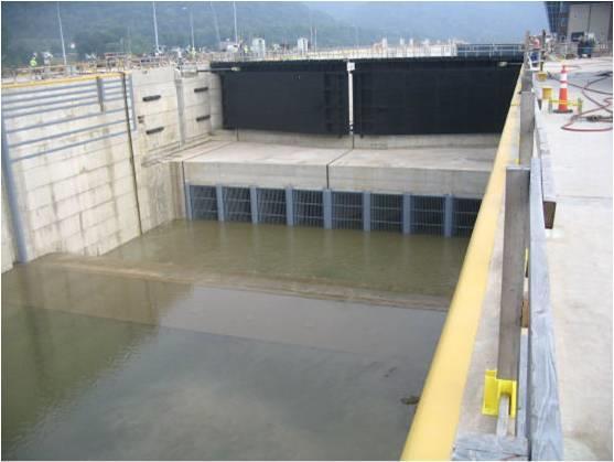
39 Completed Marmet Lock 39
40 ILCS Offers Potential Cost Savings in Wall Construction Culvert Locations for the Sidewall Port and ILCS Filling and Emptying Systems 40

41 In-chamber Longitudinal Culvert System Sidewall Port System 41
42 In-chamber Longitudinal Culvert System (ILCS) 42

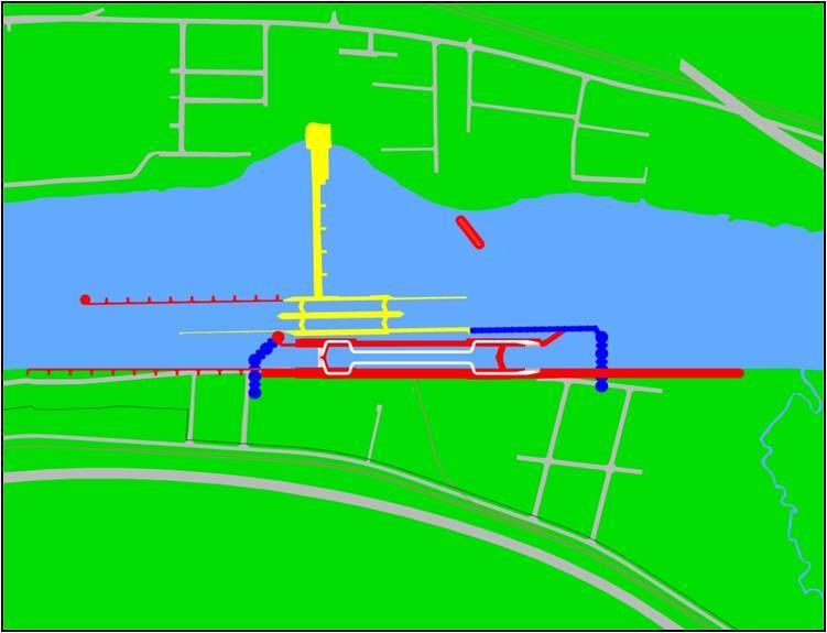
43 Intake Manifolds McAlpine Lock Layout Fit Existing Conditions 43

44 Intake Manifolds Marmet Lock Through-the-Sill Design Reduced Cofferdam Size 44
45 Lock Coefficients - Previous Model Studies Filling: Side Port = 0.73, ILCS = 0.64 Project Filling and Emptying System Initial Head, m Filling Lock Coefficient Emptying Reference Cannelton Model Type 45 Port Arrangement Sidewall Port Ables and Boyd (1966a) Cannelton Model Type 100 Port Arrangement Sidewall Port Ables and Boyd (1966a) Arkansas River Model Sidewall Port Ables and Boyd (1966b) Marmet Model Type 5 Chamber Design McAlpine Model Type 1 Chamber Design McAlpine Model Type 11 Chamber Design ILCS Hite (1999) ILCS Hite (2000) ILCS Hite (2000) 45

46 ILCS Manifolds Allow for alternative lock wall construction, such as RCC or in-the-wet construction Port extensions and wall baffles provide uniform distribution of flow and dissipate energy McAlpine Marmet 46

47 ILCS Research 1:25-Scale Hydraulic Model Hawser Forces Filling & Emptying Times 47
48 ILCS Filling Characteristics m lift, 5.79-m submergence, 5-min normal valve 48
49 Permissible Filling Times Sidewall Port System Allows Faster Filling than ILCS 49
50 ILCS Design Guidance Ports: Spacing chamber width dependent (~ 12m) Number port-to-culvert ratio about Groups at 1/3 points of chamber length Extensions needed on upstream group Wall Baffles: diffuse port jets near lock floor and inhibit upwelling along walls 50

51 Questions? 51
A new in-chamber double longitudinal culverts filling and emptying system for high head and large navigation lock by
 A new in-chamber double longitudinal culverts filling and emptying system for high head and large navigation lock by LI Jun 1, LIU Ben-qin 2, ZHAO Gen-sheng 3 and XUAN Guo-xiang 4 ABSTRACT Xijin hydro-junction
PHYSICAL MODEL TESTS OF ICE PASSAGE AT LOCKS
 Ice in the Environment: Proceedings of the 16th IAHR International Symposium on Ice Dunedin, New Zealand, 2nd 6th December 22 International Association of Hydraulic Engineering and Research PHYSICAL MODEL
STEALTH INTERNATIONAL INC. DESIGN REPORT #1001 IBC ENERGY DISSIPATING VALVE FLOW TESTING OF 12 VALVE
 STEALTH INTERNATIONAL INC. DESIGN REPORT #1001 IBC ENERGY DISSIPATING VALVE FLOW TESTING OF 12 VALVE 2 This report will discuss the results obtained from flow testing of a 12 IBC valve at Alden Research
CSO/STORMWATER MANAGEMENT. HYDROVEX FluidMid Flow Monitoring & Regulating Station with Siphon (Type G)
") CSO/STORMWATER MANAGEMENT HYDROVEX FluidMid Flow Monitoring & Regulating Station with Siphon (Type G) HYDROVEX FLUIDMID FLOW MONITORING & REGULATING STATION WITH SIPHON (TYPE G) APPLICATION The HYDROVEX
CSO/STORMWATER MANAGEMENT HYDROVEX FluidMid Flow Monitoring & Regulating Station with Siphon (Type G) HYDROVEX FLUIDMID FLOW MONITORING & REGULATING STATION WITH SIPHON (TYPE G) APPLICATION The HYDROVEX
NASHVILLE DISTRICT UPDATE TRVA ANNUAL CONFERENCE
 NASHVILLE DISTRICT UPDATE TRVA ANNUAL CONFERENCE 1 LTC Cullen A. Jones, P.E., PMP Nashville District Commander Great Lakes and Ohio River Division US Army Corps of Engineers (USACE) 10 October 2017 The
PAK BENG HYDROPOWER PROJECT
 PAK BENG HYDROPOWER PROJECT Hydrodynamic Characteristics Research on Valve and Culvert at Valve Section for Pak Beng Ship Lock September 2015 CONTENTS Page 1 FOREWORD... - 1-2 RESEARCH CONTENTS AND EXPERIMENT
Nero Needle Valves. Nero Needle Valves
 Nero Needle Valves Main Characteristic The needle valve is mainly designed for water flow rate and pressure regulation in a pipeline. The regulation takes place thank the axial movement of the piston,
Pumping Station. Marisa Handajani
 Pumping Station Marisa Handajani Function To lift or to elevate the liquid from a lower elevation to an adequate height at which it can flow by gravity or overcome the hydrostatic head Applications: 1.
Multilayer Energy Dissipating Inlet Column in Center-Feed Clarifiers 1
 Multilayer Energy Dissipating Inlet Column in Center-Feed Clarifiers 1 References 6,276,537 08/21/2001 Esler et al 210/519 6,800,209 10/05/2004 Wright 210/801 Field of Invention Clarifiers are tanks where
Washtenaw County DESIGN PROCEDURES AND ENGINEERING STANDARDS FOR PRESSURE DISTRIBUTION NETWORKS
 Washtenaw County Department of Planning & Environment Development Services Division DESIGN PROCEDURES AND ENGINEERING STANDARDS FOR PRESSURE DISTRIBUTION NETWORKS 705 N. Zeeb Road Phone: (734) 222-3800
No. of Single leaf Sector Gates 2 Clear span of opening 7.0m Cylinder rebate size. Sill level inner gate Gate crest level - inner.
 YARINGA MARINA SINGLE LEAF SECTOR GATES 1.1 Leading Particulars No. of Single leaf Sector Gates 2 Clear span of opening 7.0m Cylinder rebate size To suit Sector gate depth above sill - 6.5m outer Sill
INTERNATIONAL JOURNAL OF APPLIED ENGINEERING RESEARCH, DINDIGUL Volume 1, No 4, 2011
 Numerical modal analysis of Howell Bunger valve using FEM method Farid Vakili Tahami, Mohammad Zehsaz, Mohammad Ali Saeimi Sadigh, Amin Paykani Department of Mechanical Engineering, University of Tabriz,
CSO/STORMWATER MANAGEMENT. HYDROVEX FluidHook Control Gate Valve
 CSO/STORMWATER MANAGEMENT HYDROVEX FluidHook Control Gate Valve HYDROVEX FLUIDHOOK CONTROL GATE VALVE APPLICATION The flow regulation at storm overflows or retention facilities is usually performed with
City of Peachtree City
 City of Peachtree City Lake Peachtree Spillway Replacement City Council Update September 15, 2016 Project Team Integrated Science & Engineering 1 Spillway Alternatives Analysis Spillway Alternatives Evaluated
Improving the Waterway While Using the Waterway ~ The Chelsea Street Bridge Replacement Project
 Improving the Waterway While Using the Waterway ~ The Chelsea Street Bridge Replacement Project An Overview of Chelsea River The Chelsea River- of strategic importance The Port of Boston handles approximately
Rodney Hunt. A GA Industries Company Bascule and Pelican Gates
 Rodney Hunt A GA Industries Company Bascule and Pelican Gates Hinged Crest Gates Precise Flow and Level Control Fully Functional in Ice Conditions Proven Performance One Source: Design, Build, Actuate
CHAPTER 10 FLOATING WHARVES
 CHAPTER 10 FLOATING WHARVES Both the US Army and Navy have floating equipment suitable for constructing floating wharves. The most promising equipment of each service is discussed below. Section I. Army
Applied Fluid Mechanics
 Applied Fluid Mechanics 1. The Nature of Fluid and the Study of Fluid Mechanics 2. Viscosity of Fluid 3. Pressure Measurement 4. Forces Due to Static Fluid 5. Buoyancy and Stability 6. Flow of Fluid and
STRUCTURE S-13. Revised 2/21/02
 STRUCTURE S-13 This structure is a pumping station with a gated spillway which can control flows which bypass the pumps. The structure is located in Canal 11 (South New River Canal) about 300 feet west
Design Standard - Fume Hoods & Fume Hood Exhausts
 Design Standard - Fume Hoods & Fume Hood Exhausts 1.0 Introduction The fume hood is the primary control device in most laboratories for protecting employees and students from exposure to hazardous chemicals.
Metrovick F2/4 Beryl. Turbo-Union RB199
 Turbo-Union RB199 Metrovick F2/4 Beryl Development of the F2, the first British axial flow turbo-jet, began in f 940. After initial flight trials in the tail of an Avro Lancaster, two F2s were installed
Operation and Maintenance of Electro-Mechanical Equipment of Sabalan Dam
 Operation and Maintenance of Electro-Mechanical Equipment of Sabalan Dam M.Rezaifardi & Sh.Partovi Azar Dam department, Ashenab Consulting Engineers Company, Iran ashenab.icold@gmail.com ABSTRACT Dams
CSO/STORMWATER MANAGEMENT. HYDROVEX CCV Check Valve
 CSO/STORMWATER MANAGEMENT HYDROVEX CCV Check Valve HYDROVEX CCV CIRCULAR CHECK VALVE APPLICATION The HYDROVEX CCV Check Valve is designed for use in water and sewage. It has no reinforcement and is especially
Sleeve Valves Energy Dissipaters
 Sleeve Valves Energy Dissipaters Engineering Creative Solutions for Fluid Systems Since 1901 A Tradition of Excellence With the development of the first rubber seated butterfly valve more than 70 years
PRESSURE REDUCING VALVE
 Schematic Throttles to reduce high upstream pressure to constant lower downstream pressure Low Flow By-Pass controls at low flows 4 PRESSURE REDUCING VALVE with LOW-FLOW BY-PASS FEATURE Main Line valve
PRESSURE REDUCING VALVE
 Schematic Throttles to reduce high upstream pressure to constant lower downstream pressure Low Flow By-Pass controls at low flows 4 PRESSURE REDUCING VALVE with LOW-FLOW BY-PASS FEATURE Main Line valve
Hydraulic Report. County Road 595 Bridge over Second River. Prepared By AECOM Brian A. Hintsala, P.E
 Prepared for: Prepared by: Marquette County Road Commission AECOM Ishpeming, MI Marquette, MI 60240279 December 9, 2011 Hydraulic Report County Road 595 Bridge over Second River Prepared By AECOM Brian
Fundamentals of steam turbine systems
 Principles of operation Fundamentals of steam turbine systems - The motive power in a steam turbine is obtained by the rate of change in momentum of a high velocity jet of steam impinging on a curved blade
LESSON Transmission of Power Introduction
 LESSON 3 3.0 Transmission of Power 3.0.1 Introduction Earlier in our previous course units in Agricultural and Biosystems Engineering, we introduced ourselves to the concept of support and process systems
Impacts of Short Tube Orifice Flow and Geometrical Parameters on Flow Discharge Coefficient Characteristics
 Impacts of Short Tube Orifice Flow and Geometrical Parameters on Flow Discharge Coefficient Characteristics M. Metwally Lecturer, Ph.D., MTC, Cairo, Egypt Abstract Modern offset printing machine, paper
FIXED CONE VALVE. The flow is guided by the inner vanes, in order to decrease the vortex and the vibration;
 BEI JI NG JOI NTFLOW SYSTEM CO. FI XEDCONEVALVE The Fixed cone Valve is typically operated by a manual, electric or hydraulic actuator mounted above the bevel gear. The bevel gear transmits torque to the
How to build a Hydraulic Ram Pump By Seth Johnson Land To House Version 1.1
 Seth Johnson How to build a Hydraulic Ram Pump By Seth Johnson Land To House Version 1.1 History: A man named John Whitehurst first created the Hydraulic Ram Pump in 1772. That means that this ingenious
COMPUTATIONAL FLOW MODEL OF WESTFALL'S 2900 MIXER TO BE USED BY CNRL FOR BITUMEN VISCOSITY CONTROL Report R0. By Kimbal A.
 COMPUTATIONAL FLOW MODEL OF WESTFALL'S 2900 MIXER TO BE USED BY CNRL FOR BITUMEN VISCOSITY CONTROL Report 412509-1R0 By Kimbal A. Hall, PE Submitted to: WESTFALL MANUFACTURING COMPANY May 2012 ALDEN RESEARCH
Experiment No.3: Flow through orifice meter. Background and Theory
 Experiment No.3: Flow through orifice meter Background and Theory Flow meters are used in the industry to measure the volumetric flow rate of fluids. Differential pressure type flow meters (Head flow meters)
Experiment No: 2. To determine the effectiveness of shell and tube, cross flow & plate heat exchangers. Heat Exchangers. Plate-type Extended surfaces
 Experiment No: Objective o determine the effectiveness of shell and tube, cross & plate heat exchangers heory A heat exchanger is an equipment which facilitates the of thermal energy between two or more
C O L M A N. Air Distribution PERFORATED FACE DIFFUSERS P SERIES SERIES
 C O L M A N Air Distribution E N G I N E E R E D A I R P R O D U C T S PERFORATED FACE DIFFUSERS P SERIES P SERIES PERFORATED FACE DIFFUSERS P SERIES QUALITY AND EFFICIENCY WITHOUT COMPROMISE Application:
Redundant Hydraulic and Control System at the Seabrook Gate Complex, New Orleans, LA
 Redundant Hydraulic and Control System at the Seabrook Gate Complex, New Orleans, LA Robert Ferrara, President Thomas Behling, Systems Engineer Abstract The Seabrook Floodgate complex utilizes a 95-foot
NJK Precision Product NJK-02 Sensor Installation Guide
 Precision -02 Sensor 2017 Product Line Precision Product Table of Contents Precision Company Overview - Page 2-02 Installation Guidelines - Page 3-02 Recommended Installations - Page 5-02 Non-Recommended
INSTALLATION AND OPERATING INSTRUCTIONS FOR CONCRETE VAULT TYPE UNITS
 INSTALLATION AND OPERATING INSTRUCTIONS FOR CONCRETE VAULT TYPE UNITS CONTENTS Introduction Safety Operating Principle System Installation Initial Startup System Operations Troubleshooting Maintenance
PRESSURE REDUCING VALVE
 Schematic Throttles to reduce high upstream pressure to constant lower downstream pressure Closes quickly when downstream pressure exceeds reduced pressure setpoint 3 PRESSURE REDUCING VALVE with SURGE
Lesson 5: Directional Control Valves
 : Directional Control Valves Basic Hydraulic Systems Hydraulic Fluids Hydraulic Tank Hydraulic Pumps and Motors Pressure Control Valves Directional Control Valves Flow Control Valves Cylinders : Directional
characteristics, including the ability to turn through 180 degrees for an increase in backing thrust.
 6 Turning CRP Azipod gives a boost to point marine propulsion efficiency Tomi Veikonheimo, Matti Turtiainen Almost as old as the invention of the screw propeller itself, the concept of contra-rotating
SCHOOL OF COMPUTING, ENGINEERING AND MATHEMATICS SEMESTER 2 EXAMINATIONS 2013/2014 ME110. Aircraft and Automotive Systems
 s SCHOOL OF COMPUTING, ENGINEERING AND MATHEMATICS SEMESTER 2 EXAMINATIONS 2013/2014 ME110 Aircraft and Automotive Systems Time allowed: TWO hours Answer TWO questions from THREE in Section A and TWO questions
7.4 Parshall flumes Description
 measuring ha will be in a zone of flow separation. As already mentioned in Section 7.2.3, the ratios b,/b, and bjl, are also expected to influence the head-discharge relationship. Bennett (1 972) calibrated
C O L M A N. Air Distribution CIRCULAR DIFFUSERS LRS SERIES LRS SERIES
 C O L M A N Air Distribution E N G I N E E R E D A I R P R O D U C T S CIRCULAR DIFFUSERS LRS SERIES LRS SERIES CIRCULAR DIFFUSERS L SERIES Application Colman Air Distribution L series circular swirl diffusers
Test Which component has the highest Energy Density? A. Accumulator. B. Battery. C. Capacitor. D. Spring.
 Test 1 1. Which statement is True? A. Pneumatic systems are more suitable than hydraulic systems to drive powerful machines. B. Mechanical systems transfer energy for longer distances than hydraulic systems.
Shipboard fittings and supporting hull structures associated with towing and mooring on conventional vessels ships
 (Jan 2004) (Corr.1 Feb 2004) Rev.1 July 2004) (Rev.2 Sept 2006) (Rev.3 July 2007) (Corr.1 Sept 2014) (Rev.4 Oct 2016) Shipboard fittings and supporting hull structures associated with towing and mooring
Heat Exchangers (Chapter 5)
") Heat Exchangers (Chapter 5) 2 Learning Outcomes (Chapter 5) Classification of heat exchangers Heat Exchanger Design Methods Overall heat transfer coefficient LMTD method ε-ntu method Heat Exchangers Pressure
Heat Exchangers (Chapter 5) 2 Learning Outcomes (Chapter 5) Classification of heat exchangers Heat Exchanger Design Methods Overall heat transfer coefficient LMTD method ε-ntu method Heat Exchangers Pressure
A PLAN TO INTERGRATE AND CONNECT RECREATIONAL BOATING WITH THE BATEMANS BAY BUSINESS PRECINCT (Proposal for Floating Pontoons in the CBD)
") A PLAN TO INTERGRATE AND CONNECT RECREATIONAL BOATING WITH THE BATEMANS BAY BUSINESS PRECINCT (Proposal for Floating Pontoons in the CBD) References: Meeting between representatives from; the Batemans
A PLAN TO INTERGRATE AND CONNECT RECREATIONAL BOATING WITH THE BATEMANS BAY BUSINESS PRECINCT (Proposal for Floating Pontoons in the CBD) References: Meeting between representatives from; the Batemans
Crispin Valves Operating Guide. Crispin
 Crispin Valves Operating Guide Crispin Since 1905 Crispin Multiplex Manufacturing Co. 600 Fowler Avenue Berwick, PA 18603 1-800-AIR-VALV T: (570) 752-4524 F: (570) 752-4962 www.crispinvalve.com sales@crispinvalve.com
LINE SILENCER. Copyright 2009 by PULSCO Incorporated. All rights reserved. Reproduction without permission is prohibited.
 LINE SILENCER Copyright 2009 by PULSCO Incorporated. All rights reserved. Reproduction without permission is prohibited. PRODUCT GUIDE PULSCO LINE SILENCER TABLE OF CONTENTS DESCRIPTION PAGE PULSCO LINE
Theory 6: Engine Performance - Dynamometry Test Code Section IV(2) and D-6
 and D-6") TRAINING ON ANTAM STANDARD CODE For TESTING OF KNAPSACK MISTERS CUM DUSTERS Theory 6: Engine Performance - Dynamometry Test Code Section IV(2) and D-6 2nd Training of Trainers on ANTAM Codes 16-28 October2016,
TRAINING ON ANTAM STANDARD CODE For TESTING OF KNAPSACK MISTERS CUM DUSTERS Theory 6: Engine Performance - Dynamometry Test Code Section IV(2) and D-6 2nd Training of Trainers on ANTAM Codes 16-28 October2016,
AUTOMATIC CONTROL VALVES. TIS asia
 AUTOMATIC CONTROL VALVES VALVES DEDICATED TO THE WATER DISTRIBUTION NETWORK AND HYDROPOWER SECTOR WE DO NOT SELL JUST VALVES, WE SELL A SOLUTION FOR THE EFFICIENCY OF THE WATER NETWORK TIS asia MADE IN
PRESSURE REDUCING CONTROL VALVE
 PRESSURE REDUCING CONTROL VALVE 06/08 Schematics Throttles to reduce high upstream pressure to constant lower downstream pressure Reducing setpoint is adjustable 2 (AOS) X P/L Standard Components 1 Main
Upper Mississippi River. US Army Corps of Engineers Mississippi Valley Division
 Upper Mississippi River US Army Corps of Engineers Mississippi Valley Division Locks & Dams 2017 The 9-foot Channel Navigation Project The Upper Mississippi River Illinois Waterway Navigation System includes
LINEAR DIFFUSERS AND BAR GRILLES
 LINEAR DIFFUSERS AND AR GRILLES LINEAR DIFFUSERS AND AR GRILLES LINEAR SLOT DIFFUSER PLENUMS FOR TECHZONE TYPE CEILINGS Model Series 5300TZ Plenums are designed to fit the 5000TZ Series Slot Diffusers.
ECH 4224L Unit Operations Lab I Fluid Flow FLUID FLOW. Introduction. General Description
 FLUID FLOW Introduction Fluid flow is an important part of many processes, including transporting materials from one point to another, mixing of materials, and chemical reactions. In this experiment, you
Ventilation grilles for installation into walls, sills or rectangular
 X X testregistrierung Ventilation grilles for installation into walls, sills or rectangular ducts Type Ventilation grilles with flat border construction also for continuous horizontal runs The new ventilation
Click on Warman Logo to go back to Menu WARMAN PUMPS ASSEMBLY, OPERATING AND MAINTENANCE INSTRUCTIONS PART 2Q SLURRY JET PUMPS TYPES JPC AND JPH PC2Q
 Click on Warman Logo to go back to Menu WARMAN PUMPS ASSEMBLY, OPERATING AND MAINTENANCE INSTRUCTIONS PART 2Q SLURRY JET PUMPS TYPES JPC AND JPH PC2Q WARMAN PUMPS ASSEMBLY, OPERATING AND MAINTENANCE INSTRUCTIONS
VENT SILENCER PRODUCT GUIDE
 VENT SILENCER Copyright 200 by PULSCO Incorporated. All rights reserved. Reproduction without permission is prohibited. PRODUCT GUIDE PULSCO VENT SILENCER TABLE OF CONTENTS DESCRIPTION PAGE PULSCO VENT
BERMAD Waterworks. Pressure Relief/Sustaining Valve. Model: WW Series. Features and Benefits. Major Additional Features
 Pressure Relief/Sustaining Valve Prioritizing pressure zones Ensuring controlled pipeline fill-up Preventing pipeline emptying Pump overload & cavitation protection Safeguarding pump minimum flow Excessive
GB-250. Submittal Specifications Installation Application Specific Details
 GREASE INTERCEPTOR TECHNICAL DATA Submittal Specifications Installation Application Specific Details 68" (1,727 mm) 13½" (343 mm) 51½" (1,308 mm) 38" (965 mm) SUBMITTAL 33½" (851 mm) STANDARD: 4" plain
Chapter 2. The Vehicle-Tank Metering System
 Chapter 2 The Vehicle-Tank Metering System Chapter Objectives Upon completion of this chapter, you should be able to: 1. Describe the vehicle-tank metering system, its uses, and its relation to other liquid-volume
(3) (4) (6) (5) (10) (9) (8) (7)
 (4) (6) (5) (10) (9) (8) (7)") 3. Fuel System A: GENERAL The fuel pressurized by the fuel tank inside pump is delivered to each fuel injector by way of the fuel pipe and fuel filter. Fuel injection pressure is regulated to an optimum
3. Fuel System A: GENERAL The fuel pressurized by the fuel tank inside pump is delivered to each fuel injector by way of the fuel pipe and fuel filter. Fuel injection pressure is regulated to an optimum
Appendix I Draft Transmission Towers and Lines Relocation Options at the Port of Long Beach
 Appendix I Draft Transmission Towers and Lines Relocation Options at the Port of Long Beach Transmission Towers & Lines Relocation Options at the Port of Long Beach December 2008 Prepared by Parsons 2201
Mounting and Operating Instructions EB 5894 EN. Electric control valves with jet pump. Flanged version of valve with jet pump
 Electric control valves with jet pump Type 3267/5824, Type 3267/5825, Type 3267/3374, Type 3267/3274 Pneumatic control valves with jet pump Type 3267-1, Type 3267-7 Flanged version of valve with jet pump
Shipboard fittings and supporting hull structures associated with towing and mooring on conventional ships
 (Jan 2004) (Corr.1 Feb 2004) Rev.1 July 2004) (Rev.2 Sept 2006) (Rev.3 July 2007) (Corr.1 Sept 2014) (Rev.4 Oct 2016) (Corr.1 Dec 2016) (Corr.2 Mar 2017) Shipboard fittings and supporting hull structures
Fluid Flow Conditioning
 Fluid Flow Conditioning March 2014 Flow Conditioning There is no flow meter on the market that needs flow conditioning. All flow meters are effective without any type of flow conditioning. 1 Flow Conditioning
PUMP TYPES. Pump Sizing. Dose to Gravity. Pumping to Gravity Distribution. Systems that need a Lift. Distribution Box and Tiered Trenches.
 PUMP TYPES Sump Clean Water Only Systems that need a Lift Effluent Multi stage Single stage Sewage Grinder Pumping to Gravity Distribution When STA is at higher elevation than septic tank Pump Sizing TDH
CSO/STORMWATER MANAGEMENT. HYDROVEX Turbo Flow Regulator
 CSO/STORMWATER MANAGEMENT HYDROVEX Turbo Flow Regulator HYDROVEX TURBO FLOW REGULATOR APPLICATION The HYDROVEX Turbo Flow Regulator is a turbine driven vortex flow regulator. It is a development of the
Exhaust System - 2.2L Diesel
 Page 1 of 9 Published: Mar 8, 2007 Exhaust System - 2.2L Diesel COMPONENT LOCATION - WITH DIESEL PARTICULATE FILTER Item Part Number Description 1 Exhaust manifold (ref only) 2 Pressure differential sensor
Project Description - 1 -
 Project Description The Mother Ann Lee Hydroelectric Station is located at Lock and Dam 7 on the Kentucky River. This dam is part of a system of 14 lock and dams installed on the Kentucky River between
Navigation Structures: Robotic platform for the detection of corrosion and protective coating thickness above and below water
 9 th European Workshop on Structural Health Monitoring July 10-13, 2018, Manchester, United Kingdom Navigation Structures: Robotic platform for the detection of corrosion and protective coating thickness
Memorandum October 5, 2017
 614 Magnolia Avenue Ocean Springs, Mississippi 39564 228.818.9626 Memorandum October 5, 2017 To: Gary Miller, U.S. Environmental Protection Agency From: David Keith, John Laplante, Matt Henderson, and
EQUAL DISTRIBUTION OF WASTEWATER USING LOW-PRESSURE DISTRIBUTION Larry D. Stephens, P.E. *
 EQUAL DISTRIBUTION OF WASTEWATER USING LOW-PRESSURE DISTRIBUTION Larry D. Stephens, P.E. * INTRODUCTION Experience with onsite systems has proven that equal application of wastewater over the entire soil
Annex I Tested by (name + signature)...: Approved by (name + signature)...: Date of issue... : 22/11/2012. TUV RHEINLAND ITALIA S.r.l.
...: Approved by (name + signature)...: Date of issue... : 22/11/2012. TUV RHEINLAND ITALIA S.r.l.") TEST REORT Rotating electrical machines art 5: Degrees of protection provided by the integral design of rotating electrical machines (I code) Classification Report Reference No....: 28105442 002 Annex
TEST REORT Rotating electrical machines art 5: Degrees of protection provided by the integral design of rotating electrical machines (I code) Classification Report Reference No....: 28105442 002 Annex
Wet pipe low flow foam/water manifold system
 December 6, 2010 Foam 15a 1. Description With the Wet Pipe Low Flow Foam/Water Manifold System, multiple risers can be supplied from a single proportioning device. A riser manifold is installed with various
LEAD FREE * LFM115 (Globe) LFM1115 (Angle)
 LFM1115 (Angle)") ES-ACV-SB-LFM115_LFM1115 LEAD FREE * Pressure Reducing Control Valve Schematic Throttles to reduce high upstream pressure to constant lower downstream pressure Reducing setpoint is adjustable 2 (AOS) P/L
ES-ACV-SB-LFM115_LFM1115 LEAD FREE * Pressure Reducing Control Valve Schematic Throttles to reduce high upstream pressure to constant lower downstream pressure Reducing setpoint is adjustable 2 (AOS) P/L
M&H AWWA C508 STANDARD SWING CHECK VALVES
 GENERAL M&H AWWA C508 STANDARD SWING CHECK VALVES Style 59-02 plain / 159-Lever & Weight / 259-02 Lever & Spring Sizes 2 Through 36 Water / Sewage Service M&H Swing Check valves are widely specified by
CANADIAN SPECIFICATIONS
 2016 Dodge Durango Specifications are based on the latest product information available at the time of publication. All dimensions are in millimetres (inches) unless otherwise noted. All dimensions measured
Drip In PC Pressure Compensating Dripline
 Pressure Compensating Dripline Micro-Irrigation A technologically superior and cost effective way to irrigate Difficult topographical conditions Low and varying water pressures Installations requiring
TRASH RACK CLEANING MACHINE
 TRASH RACK CLEANING MACHINE 1 SCOPE The work includes the design, manufacturing, supply, transportation, handling, storage, installation (including 1 st and 2 nd Stage embedded parts and any other necessary
EPIC J3413. Uniclass L L2123. CI/SfB (52.5) In6. The most advanced drainage system of its kind. ACO Qmax. Technical Data
 In6. The most advanced drainage system of its kind. ACO Qmax. Technical Data") Uniclass L7315 + L2123 EPIC J3413 CI/SfB (52.5) In6 The most advanced drainage system of its kind ACO Qmax Technical Data ACO Qmax System Contents Load Classes 3 ACO Qmax 600 System Pedestrian and Car
Uniclass L7315 + L2123 EPIC J3413 CI/SfB (52.5) In6 The most advanced drainage system of its kind ACO Qmax Technical Data ACO Qmax System Contents Load Classes 3 ACO Qmax 600 System Pedestrian and Car
LEAD FREE * LFF115 (Globe) LFF1115 (Angle)
 LFF1115 (Angle)") ES-ACV-SB-LFF115_LFF1115 LEAD FREE * Pressure Reducing Control Valve Schematics Throttles to reduce high upstream pressure to constant lower downstream pressure Reducing setpoint is adjustable 2 (AOS)
ES-ACV-SB-LFF115_LFF1115 LEAD FREE * Pressure Reducing Control Valve Schematics Throttles to reduce high upstream pressure to constant lower downstream pressure Reducing setpoint is adjustable 2 (AOS)
3.1 Overview of ATCO Electric s URD System Design
 Page: 3-1 3.0 URD DESIGN GUIDELINES 3.1 Overview of ATCO Electric s URD System Design The power supply to all single lot underground residential services is through front lot service. Single phase transformers
TECHNICAL REFERENCE CLEANING POWER GUIDELINES TANKJET TANK CLEANER OVERVIEW BY TANK DIAMETER OPTIMIZING TANK CLEANING OPERATIONS
 OPTIMIZING TANK CLEANING OPERATIONS CLEANING POWER GUIDELINES Choosing a tank cleaner is based primarily on tank size and level of cleaning required. Understanding the definitions that follow will help
Bucket Elevators. hayes-stolz.com
 Bucket Elevators hayes-stolz.com BUCKET ELEVATORS The rugged design and heavy-duty construction of Hayes & Stolz Bucket Elevators ensure reliable performance for the most demanding elevating requirements.
Upper Mississippi River
 US Army Corps of Engineers Mississippi Valley Division Upper Mississippi River Locks & Dams Front Cover: (May 2009) Locks and Dam 15, Rock Island, Ill. An 80-ton auxiliary lock miter gate is steadied into
DRAFT REPORT TXDOT SH 183 MASTER DRAINAGE STUDY HYDRAULIC ANALYSIS OF ELM FORK OF TRINITY RIVER CROSSING AT SH 183 WITHIN THE ELM FORK WATERSHED
 DRAFT REPORT TXDOT SH 183 MASTER DRAINAGE STUDY HYDRAULIC ANALYSIS OF ELM FORK OF TRINITY RIVER CROSSING AT SH 183 WITHIN THE ELM FORK WATERSHED FOR TEXAS DEPARTMENT OF TRANSPORTATION DALLAS DISTRICT CONTRACT
C O L M A N. Air Distribution LINEAR SLOT DIFFUSERS CD SERIES SERIES
 C O L M A N Air Distribution E N G I N E E R E D A I R P R O D U C T S LINEAR SLOT DIFFUSERS CD SERIES CD SERIES LINEAR SLOT DIFFUSERS QUALITY AND EFFICIENCY WITHOUT COMPROMISE Application Colman Moducel
Smart Rivers Conference September 15, 2011 New Orleans, Louisiana
 Status of Inland Waterways Infrastructure Funding Smart Rivers Conference September 15, 2011 New Orleans, Louisiana 1 The national public policy organization advocating a modern and well-maintained system
Analysis of Exhaust System using AcuSolve
 Analysis of Exhaust System using AcuSolve Abbreviations: CFD (Computational Fluid Dynamics), EBP (Exhaust Back Pressure), RANS (Reynolds Averaged Navier Stokes), Spalart Allmaras (SA), UI (Uniformity Index)
2. a) What is pantograph? What are its uses? b) Prove that the peaucellier mechanism generates a straight-line motion. (5M+10M)
 What is pantograph? What are its uses? b) Prove that the peaucellier mechanism generates a straight-line motion. (5M+10M)") Code No: R22032 R10 SET - 1 1. a) Define the following terms? i) Link ii) Kinematic pair iii) Degrees of freedom b) What are the inversions of double slider crank chain? Describe any two with neat sketches.
Code No: R22032 R10 SET - 1 1. a) Define the following terms? i) Link ii) Kinematic pair iii) Degrees of freedom b) What are the inversions of double slider crank chain? Describe any two with neat sketches.
Soy Transportation Coalition NCSL Legislative Summit August 20, 2014
 Soy Transportation Coalition NCSL Legislative Summit August 20, 2014 Why Should Farmers Care About Transportation? Because our international competitiveness depends on it. Costs of transporting soybeans:
first flust water diverters water quality first downpipe, post/wall mounted and in-ground diverters
 water quality first downpipe, post/wall mounted and in-ground diverters Available in kit form just add PVC pipe Simple, effective and easy to install Includes Slow Release Control Valve - empties after
T95 Load Cell Assembly for Silo, Tank & Vessel Weighing and Axle Weighing
 T95 Load Cell Assembly for Silo, Tank & Vessel Weighing and Axle Weighing Capacities 2t to 20t Stainless Steel Load Sensor OIML C3 approved Integrated Lift Off Prevention Load cell is always in Tension
11/12/2014. Jay Ruble Crounse Corporation
 Jay Ruble Crounse Corporation The U.S Inland waterways system includes 12,000 miles of commercially navigable channels and some 240 lock sites. These inland highways move commerce to and from 38 states,
STUDY OF HYDROGEN DIFFUSION AND DEFLAGRATION IN A CLOSED SYSTEM
 STUDY OF HYDROGEN DIFFUSION AND DEFLAGRATION IN A CLOSED SYSTEM Yuki Ishimoto 1, Erik Merilo 2, Mark Groethe 2, Seiki Chiba 3, Hiroyuki Iwabuchi 1, Kou Sakata 1 1 The Institute of Applied Energy, 14-2,Nishishinbashi
AN EXPLANATION OF CIRCUITS CARTER YH HORIZONTAL CLIMATIC CONTROL CARBURETER
 AN EXPLANATION OF CIRCUITS CARTER YH HORIZONTAL CLIMATIC CONTROL CARBURETER The Carter Model YH carbureter may be compared with a Carter YF downdraft carbureter with the circuits rearranged to operate
Chapter 6. Supercharging
 SHROFF S. R. ROTARY INSTITUTE OF CHEMICAL TECHNOLOGY (SRICT) DEPARTMENT OF MECHANICAL ENGINEERING. Chapter 6. Supercharging Subject: Internal Combustion Engine 1 Outline Chapter 6. Supercharging 6.1 Need