FLIGHT MANUAL. UL airplane. SHARK.AERO s.r.o SHARK.AERO CZ s.r.o.
|
|
|
- Cecil Washington
- 5 years ago
- Views:
Transcription


1 FLIGHT MANUAL UL airplane SHARK.AERO s.r.o SHARK.AERO CZ s.r.o. Version: AFM Shark-EN 60_ _final created from Czech original version : AFM_Shark-CZ_60_ _certifikat.doc
2
3 Airplane Type / version: SHARK UL Serial number: Registration: Date of issue: LAA - Approval number and date: ULL - 05 / / Manufacturer stamp and signature : The airplane must be operated according to informations and limitations presented in this handbook. This handbook must be available to pilot at any time of the flight.
4
5 LIST OF THE REVISIONS AND THE EPAIRS Ordinal No. Number of document - bulletin It concerns to pages No. Date of issue Signature 1/13 2-1,2-2,2-6,2-9, 3-1 to 3-3, 3-6 to to to to 7-10 appendix 3-3 format editing V.Pekár 2/13 2-6,2-7,6-1 to V.Pekár 3/13 2-6, 5-1,5-2,6-4,6-5, V.Pekár 4/15 2-4, 2-6, 7-10, 7-18, J. Skočej 5/ ,2-3,2-4,2-6, 3-6, 4-3, V.Pekár 4-7, 4-11,4-12, 5-2 to 5-6, 6-6, 7-1, 7-10, 7-11, 7-12, 7-14, 7-15, 7-18 to 7-27, 8-6 6/ V.Pekár 7/ to 3-9, 5-2, 5-3, 7-1, V.Pekár 7-7, 7-14,7-19 to / , 6-7 to V.Pekár 9/ , 2-1, 2-8, 2-9, 4-15, 6-2, 6-4, / Rewritten as a part of the LAA type certification requirements V.Pekár J.Dostál
6
7 Content 1. General Introduction Certification bases Warnings, cautions and notes Airplane basic description Three view drawing Limitations Airspeed Airspeed indicator markings analog airspeed indicator markings Engine Engine instrument marking Weight limits Center of gravity (CG) Approved maneuvers Maneuvering load factor G Flight crew Kind of operation Fuel Approved fuel types Fuel tanks capacity Other limitations Placards Emergency procedures Engine failure and emergency landing Engine failure during take-off run Engine failure during take-off In-flight engine failure Carburettor icing In-flight engine restart Fire Engine fire on the ground Engine fire during take-off Engine fire in flight Cockpit / electrical fire Gliding Precautionary Landing Blown-Out Tire Landing Landing with Damaged Landing Gear Landing gear retraction malfunction Landing gear opening malfunction Vibrations from engine or other engine problem
8 3.11. Inadvertent icing encounter Extreme turbulence encounter Electrical system malfunctions Inadvertent Stall and spin recovery Stall recovery Spin recovery USe of Rescue system Normal procedures Pre-flight inspection Cockpit Wing Landing gear Powerplant Control cables Tail unit and fuselage Turning on of electric devices Engine starting Engine warm-up and test Before taxiing Taxiing Check on holding line normal take off Climb Cruise Approach Descent Downwind Normal landing On Base Leg On Final Landing After landing Engine shut down Post-Flight Check Short field take-off and landing procedures Balked landing procedures Fuel SYSTEM use REPEATED TAKE OFF High speed flights Turbulences Maneuvering Landing gear opening Propeller, engine RPM
9 Flaps Landing gear retraction Flutter, high altitude flights Performance Airspeed indicator system calibration Stall speed TAKE-OFF Distance In flight adjustable prop. NEUFORM TXR2-V In flight adjustable prop. Woodcomp SR3000/2WN On ground adjustable prop. DUC SWIRL Landing distance Rate of climb Cruise, endurance, range Airplane empty weight and COG determination Weight and center of gravity determination for flight Technical Description of the airplane AIRFRAME Fuselage Cockpit canopy Engine cowlings Wing Ailerons Flaps Horizontal stabilizer Elevator Rudder Airplane exterior surface painting Landing gear Front undercarriage Main undercarriage Undercarriage retraction and extension CONTROL SYSTEMS Elevator control Aileron control Rudder control Flaps Elevator trim tab control ELECTRIC SYSTEM Fuel system COCKPIT - interior and instruments POWER UNIT Technical data PROPELLER
10 DUC SWIRL 3 blade, on the ground adjustable propeller, diameter 1680 mm Woodcomp SR W two blade in flight electrically adjustable propeller Woodcomp KW 20W - two blade hydraulically in flight adjustable Neuform TXR2-V Rescue system Description of rescue system Stratos/Junkers Magnum The activation mechanism Rescue system installation Towing system Position lights Landing Light ELT Unit Autopilot Airplane handling, care and maintenance Wing Dismounting Remove flaps Disconnect aileron controls Disconnect rear wing spar pin Disassemble the main wing spar pins Disconnect fuel hoses and fuel sensors sockets Remove wing spars out of center-wing Disconnect pitostatic system hoses Secure wings by hangaring (transport) jigs Stabilizer disassembly Parking and mooring General Cover of pitot tube Mooring Hangaring, Ground Handling Towing Tire pressure Supplements
11 1. GENERAL 1.1. INTRODUCTION This handbook is provided with your airplane to allow you obtain as much knowledge as possible for the airplane operation. Read this manual before your first flight and make sure you understand all the information summarized here CERTIFICATION BASES This aircraft was manufactured in accordance ultralight airworthiness standards and does not conform to standard category airworthiness requirements. The following standards were used for approval and testing: UL-2 LTF-UL ASTM standard Czech Republic requirements of LAA German requirements for ultralight airplanes Requirements for Light Sport Aircraft (LSA) valid in USA and used as a background for European light airplane standards WARNINGS, CAUTIONS AND NOTES The following definitions applied to WARNINGS, CAUTIONS and NOTES are used in this manual: WARNING: INFORMATION which could prevent personnel injury or loss of life CAUTION: INFORMATION which could prevent damage of equipment NOTE: INFORMATION of special importance to pilot Page 1-1
12 1.4. AIRPLANE BASIC DESCRIPTION SHARK is an all-composite low-wing ultralight airplane with retractable undercarriage, tandem seats configuration, designed for fast cross-country flights. Airplane is equipped with 100HP Rotax 912 ULS engine and one of propellers acc. paragraph 7.8. Wing span 7,9 m Length 6,85 m Height 2,3 m Wing area 9,5 m 2 MAC length 1,237 m Swept wing angles 3,53 / 13,8 / 39,8 Existing version of the airplane, approved by calculations and tests, cover installation of engines Rotax 912ULS with optional equipment. All versions are calculated and tested for MTOW 600kg, but this specific Flight manual has defined limits, valid for UL category in Czech Republic under LAA CZ. Marking of a specific airplane version is defined in introduction of this flight manual. Deviations from the basic version are described in the following box: Page 1-2
13 1.5. THREE VIEW DRAWING Page 1-3
14

15 2. LIMITATIONS All speeds shown in this manual are indicated speeds. The conversion table in chapter 5.1. can be used to get the real speeds AIRSPEED Speed IAS km/h CAS km/h V NE Never exceed speed V RA Maximal speed in hard turbulence V A Maneuvering speed V FE Maximum speed with open flaps WARNING: Above Maneuvering speed use only small deflections of control surfaces - the airplane may be easily overloaded! 2.2. AIRSPEED INDICATOR MARKINGS EFIS/EMS Dynon SkyView NEVER EXCEED SPEED: km/h CAUTION RANGE: km/h NORMAL OPERATION RANGE: km/h FLAPS OPERATING RANGE: km/h Strana 2-1
. Analog airspeed indicator, used as emergency one, may indicate slightly different speeds see item 5.1.")
16 2.3. ANALOG AIRSPEED INDICATOR MARKINGS NEVER EXCEED SPEED: 327m/h FLAPS OPERATING RANGE: km/h CAUTION RANGE: km/h NORMAL OPERATION RANGE: km/h CAUTION: All speeds in this manual are determined by primary airspeed indicator displayed on EFIS (Dynon SkyView, FLYMAP). Analog airspeed indicator, used as emergency one, may indicate slightly different speeds see item 5.1. Page 2-2
17 2.4. ENGINE SHARK is powered by 100HP ROTAX 912 ULS engine. Airplane Engine type SHARK ROTAX 912 ULS Max. take-off power (kw) 73,5 Max. continuous power (kw) 69 Max. engine speed (5 min) ot/min Max. engine speed (continuous) ot/min Max. cylinder head temperature ( C) 150 Max. oil temperature ( C) 140 Oil pressure - minimum (bar) 0,8 below 3500 rpm 2,0 above 3500 rpm Oil pressure: maximum, cold start only (bar) 7 Oil pressure: normal operation (bar) 2,0 5,0 Fuel pressure: min-max (bar) 0,15 0,4 Operation range of outside temperature -25 C + 50 C For more details see Operator s Manual for all versions of Rotax 912 supplied with the engine. WARNING: Flying this aircraft must always be done with the possibility of a safe landing due to loss of engine power. The pilot is fully responsible for consequences of such failure Page 2-3
, on separate EMS unit (MiniEIS, EMSIS, VIGILUS...) or on conventional imaging devices. An example of FLYMAP engine operating variables: Warning limits of Indicator Unit: 912 ULS TACH - Max.")
18 2.5. ENGINE INSTRUMENT MARKING The airplane is equipped with the integrated engine display. Values can be displayed in the integrated EFIS/EMS (Dynon SkyView, FLYMAP, GARMIN...), on separate EMS unit (MiniEIS, EMSIS, VIGILUS...) or on conventional imaging devices. An example of FLYMAP engine operating variables: Warning limits of Indicator Unit: 912 ULS TACH - Max. RPM [1/min] 5800 EGT - Exhaust gas temperature [ºC] 860 CHT - Cylinder head temperature [ºC] 150 OIL - Oil temperature [ºC] Oil pressure, max [bar] 7 - Oil pressure, min [bar] 0,8 - Oil pressure, normal [bar] 2 5 ERT - Engine room temperature [ºC] 70 TFUEL - Fuel temperature [ºC] 70 normal values are displayed in green color values with higher attention are displayed in yellow critical values are displayed in red Page 2-4
19 2.6. WEIGHT LIMITS Empty weight: standard version (kg) 290 kg Empty weight: fully equiped (kg) 320 kg (max 325 kg) Max. take-off weight: NO Ballistic Recovery System installed (kg) Max. take-off weight: Ballistic Recovery System installed (kg) 450 kg 472,5 kg Max. crew weight: calculated for max take-off weight (kg) 177 kg Min. crew weight: (kg) 55 kg Max. crew weight: rear seat (kg) 95 kg Max. one pilot weight: (kg) 110 kg Max. weight in baggage compartment - for solo flight from front seat (kg) 25 kg Max. weight in baggage compartment (kg) 10 kg Fuel tank filling Baggage weight MAXIMAL CREW WEIGHT (kg) depends on fuel and baggage quantity Fuel gauge full 3/4 1/2 1/4 indication 30 min of flight Fuel quantity in liters kg ,6 Max: 10 kg ½ : 5 kg Without baggage Max. crew weight has to be written indelibly for specific measured weight of airplane. WARNING: Do not exceed these weight limits. Pay attention to fuel quantity, especially when 2 persons are on board. DO NOT EXCEED maximum take-off weight. Page 2-5
20 2.7. CENTER OF GRAVITY (CG) The values for ready to fly airplane (including fuel, crew, baggage). Front center of gravity limit Rear center of gravity limit 16 % MAC 34 % MAC See Section 6 for center of gravity calculation. Retraction of landing gear moves CG 0,5-1% backwards APPROVED MANEUVERS The Shark Airplane may perform: - turns required for normal flying - practicing falls - steep turn (max. bank 60 ) WARNING: All maneuvers must be performed with a positive overload because the fuel and lubrication system is designed for positive overloads. All maneuvers must be performed in a maneuver envelope with maximum positive + 4g and negative -2g overload. WARNING: Aerobatics, intentional stalls and spins are prohibited. Maximum angle of bank: MANEUVERING LOAD FACTOR G Flap up 0 Maximum positive center of gravity load factor + 4 Maximum negative center of gravity load factor - 2 Flaps down Maximum positive center of gravity load factor + 2 Maximum negative center of gravity load factor FLIGHT CREW Minimum crew on board Maximum crew on board 1 pilot 2 persons Page 2-6
21 2.11. KIND OF OPERATION WARNING: Only VFR day flights are permitted. WARNING: IFR flights and flying in clouds is prohibited. Flights in icing conditions are prohibited FUEL Approved fuel types Premium unleaded automtive fuel (Natural 95 in Czech - Standard spec. for Automotive Spark-Ignition Engine Fuel, ASTM D 4814) or AVGAS 100 LL. NOTE: Due to the higher lead content in AVGAS, the wear of the valve seats, the deposits in combustion chamber and lead sediments in the lubrication system will increase. Therefore, use AVGAS only if other fuel types are not available. For more details see Operator s Manual for all versions of Rotax 912 supplied with the engine Fuel tanks capacity Fuel tank types Standard Long Range Fuel tank capacity (each wing tank) 50 liters 75 liters Total fuel capacity 100 liters 150 liters Unusable fuel 1 liter Page 2-7
22 2.13. OTHER LIMITATIONS Max. crosswind component Max. wind in runway direction Maximum outside temperature Minimum outside temperature 16 knots ( 8 m/s ) 30 knots ( 15 m/s ) 50 C -25 C Heavy rain or excessive moisture can cause mild decrease of airplane performance. During these poor conditions we recommend to increase take-off and landing speed approximately about 10 km/hour. WARNING: No smoking on board! Page 2-8
23 2.14. PLACARDS Production label: SHARK.AERO SHARK UL 034/2017 The serial number of the particular airplane (total serial number / year of manufacture) Registration label: Matriculation: Producer: SHARK Aero spol. s r.o. SHARK Type/Name : Production number/year: Empty weight: kg Max. take-off weight: 472,5 kg Front and rear seat / luggage weight limit label: Front seat limit Rear seat limit Luggages limit solo 110 kg 0 kg 25 kg 2+lugg. 110 kg kg 10 kg 2 max 110 kg kg 0 kg Basic information placards: This product is not subject of the Czech Civil Aviation Authority approval and is operated at the user's own risk. AEROBATICS MANEUVERS AND INTENTIONAL SPINS ARE PROHIBITED Page 2-9
24 Basic LAA CZ label: OPERATION INFORMATIONS AND LIMITS - speeds IAS Matriculation Empty weight kg Max. take-off weight kg Max. payload kg Max. baggage weight for 1 pers. / 2. pers. 25 / 10 kg Min / Max. pilot weight Max. passanger weigh (rear seat) 55 / 110 kg 95 kg Stalling speed with flaps V SO 50 km/hour Max. speed with not-retracted undercarriage V LO 150 km/hour Maximum flap extended speed V FE 143 km/hour Max maneuvering speed V A 175 km/hour Max speed in hard turbulency V RA 249 km/hour Never exceed speed V NE 327 km/hour Fuel tank filling Baggage weight MAXIMAL CREW WEIGHT (kg) DEPEND ON FUEL AND BAGGAGE QUANTITY Fuel gauge indication 30min full 3/4 1/2 1/4 of flight Fuel quantity in liters Max: 10 kg ½ : 5 kg Without baggage Engine limit information: ENGINE SPEED Max. take-off (max 5min) Max. continuous Idling rpm rpm rpm Page 2-10
25 50 liters Natural 95 min. MON 85 RON 95 FUEL TANK VOLUME. LIMIT - standard Baggage max. / solo flight 10 / 25 kg tyre 300 kpa 75 liters Natural 95 min. MON 85 RON 95 FUEL TANK VOLUME LIMIT - LongRange BAGGAGE WEIGHT LIMIT TYRES PRESSURE - on the wing, walk-around area for access to cockpit - on the aerodynamic control surfaces Rescue system info - on the tail / small on the Rescue System cover Page 2-11
26
27
28
29 3. EMERGENCY PROCEDURES This section provides checklist of emergency situations which may occur. Emergency situations caused by airplane or engine malfunction are extremely rare with proper preflight inspections and maintenance. However, an emergency situation may occur. The guidelines, described in this section, should be applied to solve the problems. All air speed values in this chapter are presented in km/h - Indicated Airspeed ENGINE FAILURE AND EMERGENCY LANDING Engine failure during take-off run - throttle reduce to idle - ignition off - master switch off - brakes as required Engine failure during take-off - airspeed km/h - landing site - below 150 ft - land straight ahead - above 150 ft - choose suitable landing area in the runway direction or nearest suitable site clear of obstacles. - master switch off - ignition off - fuel tank valve shut - fuel pump off - flaps extend as needed - undercarriage extended / check - safety belts tighten after touchdown: - brakes as required Page 3-1
30 In-flight engine failure - airspeed 120 km/h - trim trim - landing site selection select Check situation, if master switch and ignition are on and fuel valve is open, continue according to procedure 3.2. (in-flight engine start) or by emergency landing according to procedure (if the engine cannot be started up) Carburettor icing - airspeed 140 km/h (optimal) - throttle try to find RPM with smallest loss of power - leave the icing area (if possible) - after 1-2 minutes increase slowly engine power to cruise speed - when engine power is not recovered, land on the nearest airfield or off-airfield following the procedure described in Chyba! Nenašiel sa žiaden zdroj odkazov IN-FLIGHT ENGINE RESTART - airspeed 120 km/h - master switch on - fuel tank valve open tank with more fuel (check) - choke closed (as the engine is warm) - fuel pump on - throttle idle (when choke is activated), 1/3 of travel otherwise. - ignition on - starter start up - if the engine cannot be started up (not enough power from battery), increase the airspeed to km/h to rotate the propeller to support the engine starting. WARNING: Loss of height needed for in-flight engine starting is approximately 600 ft. Page 3-2
31 3.3. FIRE Engine fire on the ground - fuel tank valve off - throttle full - ignition off - master switch off - leave the airplane and extinguish fire (if possible) - fire damage inspect WARNING: DO NOT TAKE ANY FURTHER FLIGHT BEFORE THE FIRE CAUSE HAS BEEN DETERMINED AND REPAIRED Engine fire during take-off - throttle idle - fuel tank valve off - if already airborne keep airspeed 120 km/h and land - brakes as necessary to stop the airplane after the airplane stops: - throttle full - ignition off - leave the airplane and extinguish fire (if possible) Engine fire in flight - fuel tank valve off - throttle full - airspeed increase try to extinguish the flames. Do not exceed V NE - landing site selection use nearest airfield or a suitable landing site for emergency landing - ignition off - master switch off - airspeed 120 km/h - wings flaps extend as needed - undercarriage extend/check - safety belts tighten - perform emergency landing - leave the airplane and extinguish fire (if possible) WARNING: DO NOT ATTEMPT TO RESTART THE ENGINE Page 3-3
32 WARNING: DO NOT TAKE ANY FURTHER FLIGHT BEFORE THE FIRE CAUSE HAS BEEN DETERMINED AND REPAIRED REPAIRED Cockpit / electrical fire - cockpit vents and windows open all vents and windows to remove smoke from the cockpit - electric equipment switches switch off all electric equipment not needed for safe landing Land as soon as possible. Extinguish fire as soon as possible GLIDING Optimal gliding speed 125 km/h Gliding ratio (at km/h), no flaps 1 : PRECAUTIONARY LANDING - choose suitable landing site, evaluate wind (direction and speed), surface, slope and obstacles - perform a fly-over at a speed of 125 km/h, above the selected landing site at suitable height (150 ft recommended), observe the landing site - follow normal landing checklist and land after touchdown perform following: - ignition off - master switch off - fuel tank valve off - brakes as required 3.6. BLOWN-OUT TIRE LANDING Use normal approach and landing procedure, keep damaged wheel above the ground during the flare as long as possible using ailerons (or elevator for the nose wheel). Page 3-4
33 3.7. LANDING WITH DAMAGED LANDING GEAR Use normal approach and landing procedure, keep the damaged wheel, or unopened wheel, or wheel with unlocked leg, above ground during the flare as long as possible using ailerons (or elevator for the nose wheel) LANDING GEAR RETRACTION MALFUNCTION - switch off landing gear circuit switch/breaker - climb to safe altitude where you can continue flight without stress - switch on landing gear circuit/breaker and activate landing gear opening procedure speed bellow 130 km/h - check visually locked landing gear struts - do not use airplane if landing gear system is not checked, repaired and adjusted by authorised person. Note: Electric system of landing gear has safety switch installed, activated by air pressure from pitostatic tube. This system block retracting below speed 115 km/h, and activates warning sound and blinking alarm if all 3 legs are not opened and locked below this speed LANDING GEAR OPENING MALFUNCTION If any malfunction occurs during opening procedure of landing gear - switch off landing gear circuit switch/breaker - climb to safe altitude where you can continue flight without stress - reduce and keep speed on 120 km/h - switch on landing gear circuit switch/breaker and activate landing gear opening procedure - if landing gear is not fully opened and locked, activate retracting of LG, and then try to open it again. Combination of plus and minus G load can help release the system if there is a mechanical failure - if some leg of landing gear is not fully open or locked, use landing gear emergency release. Open small flaps, reduce speed to 120 km/h, switch off landing gear circuit, pull off red emergency release handle of dysfunctional leg - check visually locked landing gear struts Page 3-5
34 EMERGENCY LANDING GEAR EXTRACTING - if you have any doubts the landing gear is properly open and locked, check visually yellow-black flag-arrow via check windows - this visual check is superior to electronic information - in case of one leg stays locked, safe procedure is to retract other legs as well, and perform belly landing. When landing on grass, close flaps, stop engine with 2 blades proppeler in horizontal position to reduce demage to minimum CAUTION: When landing gear emergency release is used, landing gear stays open without possibility to retract it without re-assembling by authorised technician! VIBRATIONS FROM ENGINE OR OTHER ENGINE PROBLEM Vibrations: - use engine power with minimal vibrations - in case the airplane has in flight adjustable propeller try to find in manual control regime angle with minimal vibrations - land as soon as possible, consider off-airfield landing if vibrations increase Oil pressure drop - probability of engine failure. In this case reduce engine power and land as soon as possible (before the failure occurs), consider off-airfield landing INADVERTENT ICING ENCOUNTER - throttle increase above normal cruise settings - course reverse or alter as required to avoid icing - altitude climb (if possible) EXTREME TURBULENCE ENCOUNTER - airspeed recommend 200 km/h (V RA=249 km/h) - safety belts tighten - loose objects fixed Page 3-6
35 3.13. ELECTRICAL SYSTEM MALFUNCTIONS In case of electric system malfunction we have 3 indicators providing informations about system status. Charging indicator - red LED on left top edge of instrument panel. Providing primary information about electric regulator status. - normal function: with the ENGINE START switch on, and engine turned off, the LED is blinking, because generator doesnt provide energy. With running engine, generator provides energy, regulator provides volts and ampers to appliances and for battery charging, and LED stops blinking. - failure: is signalised by blinking of red LED, while the engine is running, it signalizes the regulator doesn t provide energy. Appliances take energy from main battery or backup batteries, which have limited cappacity. The flight may continue for several minutes. Carburator engine will run even in full failure of electric system, energy for spark plugs is generated by magnetos, independent on the rest of the electric system. Engine with injection fuel system is limited by battery capacity, as it needs power for high pressure fuel pump and electronic control unit. Appliances requiring electric power will run until the batteries run out. With both batteries discharged, electric control of landing gear will be inoperative. Emergency opening of landing gear manually will be necessary. Flaps will be inoperative, landing will be possible with closed flaps only. Radio and transponder will be inoperative too. Voltmeter: when the engine is off, voltmeter shows battery voltage. Normal value is between 12 to 13,5 V. Below 11 V the battery is empty and engine start will probably not be possible. With a running engine, voltmeter shows voltage provided by regulator. Normal level is 13,5-14,4 V. If failure of regulator occurs, followed by blinking indicator, it is necessary to check volts, if they gradually decrease with time, it signalise loss of battery voltage, battery is discharged. If battery voltage drops under 10,5 V, some instruments stop working. Damage of battery can occur in the same time. Ammeter: shows current flowing from or to the battery. With engine off, ammeter indicates possitive values, battery is providing current, is discharging. Normal level is 1 to 6 Amps, depends on the number of devices turned on. With running engine, batteries are charged, Page 3-7
36 ammeter shows negative values. When the battery is low, ampers can reach -15 Amps. When battery is charged, current slowly decreases. After few minutes of flight, battery is charged, and ammeter starts showing zero values. This indicates fully charged battery. In case of regulator failure, when current is provided by battery, the ammeter shows plus Amps. Procedure: if charging indicator is blinking - switch off all instruments unnecessary for the flight. Make safety landing at the closest airport and fix the problem INADVERTENT STALL AND SPIN RECOVERY Stall or spin should not occur during normal flight and both are prohibited Stall recovery - push down the nose of airplane by pushing the control stick to increase speed - gradually increase power Loss of altitude in straight direction after stall is: ft = m Spin recovery WARNING: Spin characteristics of the airplane have not been tested. A procedure bellow is for information purposes only. - throttle idle - aileron neutral - rudder opposite to rotation - control stick pushed Once the rotation is stopped, get rudder back to neutral position and establish a level flight. Page 3-8
37 3.15. USE OF RESCUE SYSTEM - engine off - pull red handle of ballistic recovery system placed between legs of both pilots - protect your body WARNING: Rescue system is secured by pin with red flag REMOVE BEFORE FLIGHT, which needs to be removed before every flight. In case you forget to pull the pin out, remove it before use. CAUTION: When the rescue system is used, damage of airplane always occures. Page 3-9
38

39 4. NORMAL PROCEDURES 4.1. PRE-FLIGHT INSPECTION Cockpit - Master switch and ignition off - Attachment and position of seats check, adjust - Safety belts inspect - Instruments and equipment inspect - Control stick inspect, freedom of movement - Rudder pedals inspect, freedom of movement (consider nose wheel control) - Rudder and aileron cable control inspect - Engine control inspect, freedom of movement - Brakes function - Fuel check (level) - Condition of the composite shell check and transparent canopy - Oil quantity between MIN and MAX marks Page 4-1
40 Wing - Wing inspect surface and damages - Hinges, saving inspect - Ailerons inspect, freedom of movement and deflections - Flaps, hinges, control tube, bolts, nuts, securing inspect - Fuel tank tightness and caps inspect - Pitot tube inspect - Fuel tank ventilation holes in flap hinges inspect Landing gear - Landing gear and brake system inspect - Landing gear leg and attachment inspect - Shock absorber of the nose landing gear inspect - Rubber shock absorber of the main landing gear inspect - Retracting system of undercarriage inspect (locking strut, gas springs, steel springs, cables for retracting, emergency locks + bowdens, servo for front leg, sensors for opened and retracted position) - Doors of retractable undercarriage inspect - Tire pressure check - Main and rear wing pins securing inspect - Fuel filters inspect - Connection and condition of fuel hoses inspect - Connectors and wiring to sensors in fuel tank inspect Powerplant - Engine, propeller general condition inspect - Safety pins and wires inspect - Engine mount and engine bed inspect - Exhaust silencer inspect - Ignition system inspect - Fuel system - hoses and pump inspect, drain the system - Cooling fluid inspect - Propeller turn (until you hear burp sound) - Oil level check inspect, refill if needed Page 4-2
41 Control cables - Rudder control cables inspect condition and tension - Turnbuckles, bowdens, safety wire inspect Tail unit and fuselage - Tail unit surface and damages inspect - Control surfaces freedom of movement, deflection - Trim tab inspect - Nut + securing on stabilizer rear pin inspect - Bolts + nuts + controls inspect - Fuselage inspect surface Turning on of electric devices - the audio sequence is played when the EFIS SkyView unit is turned on. It tests the sound. Radio must be turned on. - when the landing gear circuit is turned ON, the signal diodes start blinking and acoustic signal is played. This checks functionality of these devices. - when flaps circuit is turned ON, top green LED starts blinking, and it is necessary to press related button. If flaps are not in zero position, they will retract to zero position ENGINE STARTING - pre-flight inspection completed - safety belts adjust and fasten - instruments values check, settings - canopy closed, locked - master switch switch on - fuel tank valve (left / full tank) open - choke activate (cold engine only) - throttle Idle for cold engine, 1/3 of travel for warm engine - cowl flaps open - pre-heating of carburettors as required - fuel pump on (if left tank is used) - control stick pulled - brakes on - propeller area clear - ignition switch on - starter turn on for max 10 sec, then 2 min. cooling - after engine start up set the idle speed Page 4-3
42 - instruments check out indication (oil pressure must rise within 10 seconds) - choke switch off slowly (cold engine only) - avionics and other switches switch on as required Engine warm-up and test - Warm up to operating temperature - first at idle or 2000 RPM for 2 minutes, then at 2500 RPM to reach oil temperature of 50 C. - Check out temperature and pressure values - must be within operating limits all the time. - Check out the maximum power - speed around 5000 RPM depends on used propeller - Check out ignition (magnetos) - set RPM - drop should not exceed 300 RPM on either magneto - difference between magnetos shouldn t exceed 120 RPM - Check idle RPM ±100 CAUTION: Perform the engine check on suitable terrain heading upwind. Consider also safety of other persons. Do not operate the engine for longer time than necessary and allow sufficient cooling before switching off BEFORE TAXIING Check from left to right: - seat adjust - headset connected - seatbelts locked, tightened Left side of cabin: - items below armrests secured, fixed - check copilot if ready headset, seatbelts - cabin closed, locked, front + rear - cabin windows closed, front + rear - kneeboard + pen write down data, time - fuel tank valve left - throttle 2500 rpm - choke closed - cooling (cowl flaps) opened - ventilations - airstream opened - items below knees secured, fixed Page 4-4
43 Left side of instrument panel: - items in drawer secured, fixed - flaps lever visual check 0,1,2,3, adjust 1 - take-off position - landing gear breaker ON - position of landing switch DOWN (neutral) - landing lights 3 green - landing gear struts arrows visual check of locked position - charging control light off >check - adjustable propeller auto, take-off or manual, set min. angle Middle of instrument panel: - GPS ON, adjust - EFIS ON, adjust - QNH adjust - AOA/stall warning ON, check function - EMS ON, check pressure and temperature in green - fuel amount quantity check, minimum 10 litres in left fuel tank - radio ON, adjust frequency, check function - intercom ON if passenger is on board, check function - transponder ON, adjust (7000) - magneto 1+2 ON - master switch ON Right side of instrument panel: - EFIS alarm LED no warning - backup altitude adjust QNH - switches/breakers ON - fuel pump ON - lights ON - optional instruments check + adjust (ELT, CO detect, FLARM, IPHONE..) Right side of cabin: - ventilation - airstream open - heating according to need - ventilation open - control stick free movement elevator + ailerons - trim neutral - items below armrest fixed, secured - items below knees fixed, secured Page 4-5
44 Middle of the cabin: - pedals adjust, free movement - brakes press, check function - parking brake open - handle of rescue system remove pin (at front seat) - runway and take-off area check of availability - radio report line-up 4.4. TAXIING The maximum taxiing speed is 10 km/h (walking speed). Always check brakes functionality as soon as the airplane start taxiing. Do not use too much brake in snowy conditions, melting ice can freeze on brake discs. Check the temperatures in summer to avoid overheating of the engine. In case of high temperatures and VAPOR LOCK risk, open the oil check cap. In temperatures above 70 o C there is a risk of VAPOR LOCK in the engine compartment, let the engine cool down CHECK ON HOLDING LINE - Cabin closed - Control check, free - Fuel selector left - Mouth opened - Flaps position 1 - Propeller take-off - Circuit breakers set (as needed) - Engine pressure and temperature check - Fuel pump ON - Trim neutral - Handle of rescue system release - Radio report Page 4-6
45 4.6. NORMAL TAKE OFF - Pedal brakes release - Throttle full power Drive straight ahead. Lift slightly nose wheel at about 50 km/h IAS. Take off at speed around 90 km/h, accelerate and climb. Do not climb until speed 115 km/h is reached. WARNING: Do not take-off when engine is not running smoothly or runway is occupied. - initial climb speed 120 km/h - engine speed reduce to max RPM - engine instruments check - landing gear retract above 150 ft, when speed is over 120 km/h, check 3 red marks - wing flaps flaps up above 150 ft, at speed 120 km/h - trim trim - fuel pump off, when level flight Note: In landing gear electric circuit is installed the pressure switch, connected to pitotstatic sytem, and adjusted to speed 115 km/h. This should prevent unintentional retraction of landing gear on the ground. Control unit does not retract landing gear, until the speed is reached. Opening of landing gear is not blocked by this switch. It works at any speed. If all 3 wheels of landing gear are not opened and locked below this speed, pressure switch activates sound and light warning system. Inspection of opened and properly locked landing gear is realized visually via small check windows CLIMB - throttle RPM max - airspeed 120 to 180 km/h as required (130 km/h best angle, 180 km/h best climbing) - temperature check maximum, if needed reduce power to avoid overheating Page 4-7
46 4.8. CRUISE - bring the airplane into horizontal flight - in-flight adjustable propeller RPM - throttle 24 inhg full (as required) - airspeed as required - engine instruments check - fuel tank valves switch between tanks when necessary WARNING: Do not forget to switch the wing tanks supplying the engine on regular basis to prevent fuel starvation. When both fuel tanks are full or almost full, always select the left tank. Followed values are recommended for ideal airplane use: Standard SHARK version Engine Rotax 912 ULS Engine speed (1/min) Power (kw) Torque (Nm) Intake pressure (in Hg) Take-off power ,5 121,0 27,5 Max. continuous power ,0 119, % ,0 97, % ,6 88, % ,0 84, APPROACH Descent - throttle as required - engine instruments check WARNING: Avoid prolonged operation with IDLE during the flight as the engine may become overcooled and lose the power. If higher descent is needed, there is possbility to extend flaps under 140 km/h, and extend the undercarriage. Side slip is not efficient, steep descend is reached with flaps III. Page 4-8
47 4.10. DOWNWIND - power rpm - airspeed reduce to km/h - engine instruments check - fuel tank valve left, if there is enough fuel - fuel pump ON, if left tank is selected - safety belts tighten - approach area and landing site situation check - undercarriage open (3 green lights on) visual check - TWR report (3 green) NORMAL LANDING On Base Leg - power rpm, or according to need - airspeed 120 km/h - engine instruments check - wing flaps take-off position ( position I ) - adjustable propeller take off position - trim trim - final leg airspace situation check On Final - airspeed km/h - power adjust as needed - engine instruments check - wing flaps landing position (II or III) - trim trim - check of landing site situation check Landing At a height 30 ft set the engine at idle speed.. Maintain speed of km/h till the flare. When flaring at a height of 1-2 ft above the ground, decelerate gradually by pulling the control stick backward till the airplane lands. Keep pulling control stick to avoid immediate contact of the front wheel with the ground. Page 4-9
48 After landing - brakes use as needed - wing flaps retract - trim neutral - flaps 0 or 1 - fuel pump off Engine shut down - power cool down the engine at rpm (if necessary) - avionics and other switches off - ignition off - master switch off - fuel tank valve off - closed - secure the airplane use parking brake, anchor an airplane, or otherwise secure the airplane against free movement Post-Flight Check Check the airplane overall condition SHORT FIELD TAKE-OFF AND LANDING PROCEDURES Normal procedures can be followed for short take off. Use second landing flaps setting together with approach speed km/h BALKED LANDING PROCEDURES - power max r.p.m - airspeed 120 km/h - engine instruments check - wing flaps take-off (position 1) - trim trim - landing gear retract, check 3 red - wing flaps retract in 150 ft - trimming trim - power max rpm - climb 120 km/h Page 4-10
49 4.14. FUEL SYSTEM USE Fuel system consists of two integral fuel tanks connected by fuel valve. It is necessary to check fuel level and switch between tanks if needed. According to requirements of engine manufacturer, the fuel system possess of return line back to left fuel tank. Electric fuel pump is installed behind fuel valve, it works for both tanks. NORMAL USE of FUEL SYSTEM: 1. START FROM LEFT FUEL TANK 2. Switch between tanks as needed. 3. Fuel return system draws fuel back into left fuel tank, pilot should check it continuously and switch back to left tank when right one is nearly empty. Do not start from right fuel tank, when left tank is full!!! Excess fuel is returned to the full left tank and continues through air vent out of the airplane REPEATED TAKE OFF During the hot days problem with engine re-startup can occur, caused by overheated fuel in the engine space,. Fuel starts boiling at C. Formed bubbles cause irregular fuel supply and engine can fails during take off. This effect is called Vapour Lock. To reduce risk of Vapour Lock, T connection of return line is placed in highest position of fuel hoses. Most of the airplanes has one or two temperature sensors inside engine space and at fuel hose installed, so pilot has information about these temperatures. Temperatures over 60 o C has yellow indication, attention is needed, over 70 o C has red indication, risk of Vapour Lock. Recommendation is to cool engine down, turn airplane against the wind and run engine at idle, or stop it and let it cool down. During hot days, we recommend to keep oil doors on upper motorcowling open, to reduce this problem. There is no risk of Vapour Lock during the flight. After take off engine compartment cools down to temperature about 20 o C above the air temperature. Engine producer recommend to use AVGAZ fuel in case of Vapor Lock issues. Page 4-11
50 WARNING: Before repeated take-off, during the hot days, is necessary to let the engine run for a longer time and test full throttle to be sure the engine fuel supply is without any problems HIGH SPEED FLIGHTS Because Shark cruising speed is higher comparing to average ultralights, there are certain risks the pilot should know about Turbulences Shark economy cruise speed is 230 km/h. Normal cruise speed is 250 km/h and during faster flights 270 km/h. Max speed at full continuous power is km/h. Max speed depends on installed systems as landing gear doors, airbox, injection, exhaust, weight, temperature, altitude. Speed 250 km/h is possible to use for planning long trips, it is acceptable even in turbulences. Speed 270 km/h is comfortable for passangers when used in conditions of lower turbulences. Speeds over 280 km/h is comfortable only in very low turbulences. In extremely high turbulences is good to reduce speed to km/h Maneuvering Maneuvering speed, when pilot can use full deflections of control system, is 170 km/h, and airplane can reach load factor 4. Normal cruising speed is significantly higher, so is is necessary to use smooth movements of control system. Fast maneuvers can easily exceed strength limits Landing gear opening Approach and entering the traffic pattern is realized at speeds around 250 km/h. At downwind position is needed to decrease speed to 130 km/h, throttle at idle speed, and decrease speed in horizontal flight without descending. Keep in mind it takes some time. Often mistake is late power reducing, higher power than idle, descending. When airplane is descending, speed doesnt decrease, and pilot can get into the stress with next procedures. Unskilled pilots has problems with higher speed range. They tend to fly at higher speeds, because of fear of stall. Page 4-12
51 Propeller, engine RPM Shark easily increase speed when maneuvering. Careful power control is required to avoid engine overrun. This is important for fixed proppeler, but keep it in mind with electrically adjustable propeller as well, because it takes about 12 seconds to change blade angles from minimum to maximum. Therefore even in constant speed mode is recommended to reduce RPM when maneuvering and work smoothly with throttle. Best propeller is hydraulically controlled, as it react very fast, and risk of engine overrun is minimal Flaps At traffic pattern, after opening landing gear, at speed 130 km/h, is recommended to reduce speed to 120 km/h and open flaps 1. Often mistake is higher speed, or speed fluctuation caused by turbulence, or incorrectly pressed button on control panel. Pressure switch, incorporated to flaps control system, is adjusted to 130 km/h. Over this speed flaps will not open, and in case they are already opened, warning will be activated. Therefore is needed to prove if flaps are really open. Another risk associated with flaps is balked landing. Pilot often in stress applies full power, and instead of climb transforms power to speed. Flaps are designed for max. speed 140 km/h. Higher speeds can cause structure overload Landing gear retraction Pressure switch is incorporated to control system of landing gear. It prevents retration below speed 115 km/h. It is recommended to keep airplane in light climb, after take-off, and wait till speed increase enough. Pilot can hold the switch for landing gear on, and wait till the airplane reaches required speed. Then the landing gear retraction sequence automaticly starts. It is recommended to check visually, if retracting procedure started lights blink, or if underarriage is really retracted 3 red lights on. Flight with opened landing gear is possible, landing gear doors was tested up to 230 km/h Flutter, high altitude flights Fast airplanes can have flutter issues. Problems can occur specially during higher speeds in high altitudes, because critical flutter speed decreases with higher altitude. Page 4-13
52 Never exceed speed VNE = 327 km/h (calibrated speed CSA = 333 km/h). Table of VNE changes with increasing altitude: Height m TAS km/h IAS km/h For higher altitude flights, keep maximum allowed speeds indicated in the previous table, or check TAS displayed by modern EFIS devices. Page 4-14
53 5. PERFORMANCE These flight performances are valid for the standard version of airplane at maximum take-off weight 472,5 kg, normal flying technique and ISA conditions (seal level, 15 C, 1013 hpa). Actual performance might be different due to pilot skills, weather and airplane conditions. WARNING: Variations in pilot technique as well as weather conditions and airplane setting (e.g. propeller pitch) can cause significant differences in flight performance AIRSPEED INDICATOR SYSTEM CALIBRATION Primary airspeed indicator EFIS (SkyView, Flymap...) IAS km/h CAS km/h Changing from cruise to take-off or landing configuration does not affect an error of air speed indicator. IAS CAS km/h km/h VS Stall speed in landing configuration VS Stall speed in clean configuration VFO Maximum speed for flap extending III VFO Maximum speed for flap extending II VFO Maximum speed for flap extending I VLO Maximum speed for extending and retracting landing gear VFE Maximum flap extended speed VA Design maneuvering speed VC Design cruise speed- gust intensity loading VRA Maximum turbulence penetration speed VH Maximum speed in level flight at maximum continuous power. VNE Never exceed speed Page 5-1
54 All speeds described in this manual are written as IAS speed, displayed by primary airspeed indicator!!! IAS - indicated speed of flight, indication of airspeed indicator in your airplane CAS - calibrated speed, real speed of flight (in zero flight level ISA) = compensated for indicator and aerodynamic error 5.2. STALL SPEED Stall speed valid for airplane weight 472,5 kg and wing level flight. Deflection indicated Stall speed km/hour IAS km/hour CAS Flaps up Flap take-off position 20 I Flaps 30 II Flaps 40 III TAKE-OFF DISTANCE In flight adjustable prop. NEUFORM TXR2-V-70 Flaps position 20 Take-off run Total take-off distance to 50 ft Grass surface 125 m 225 m Paved surface (concrete / asphalt) 105 m 205 m Flaps position 30 Take-off run Total take-off distance to 50 ft Grass surface 110 m 210 m Paved surface (concrete / asphalt) 100 m 200 m Flaps position 0 Take-off run Total take-off distance to 50 ft Grass surface 270 m 300 m Paved surface (concrete / asphalt) 240 m 270 m Page 5-2
55 In flight adjustable prop. Woodcomp SR3000/2WN Flaps position 20 Take-off run Total take-off distance to 50 ft Grass surface 130 m 225 m Paved surface (concrete/asphalt) 110 m 210 m On ground adjustable prop. DUC SWIRL 1680 Take-off Total take-off Flaps position 20 run distance to 50 ft Grass surface 185 m 290 m Paved surface (concrete/asphalt) 160 m 270 m Page 5-3
56 5.4. LANDING DISTANCE Flaps position 40 Landing ground roll Total landing distance from 50 ft Grass surface 120 m 245 m Paved surface (concrete / asphalt) 120 m 240 m Flaps position 30 Landing ground roll Total landing distance from 50 ft Grass surface 150 m 290 m Paved surface (concrete / asphalt) 150 m 290 m Flaps position 20 Landing ground roll Total landing distance from 50 ft Grass surface 175 m 355 m Paved surface (concrete / asphalt) 175 m 355 m Landing Total landing distance Without flaps (flaps 0 ) ground roll from 50 ft Grass surface 210 m 530 m Paved surface (concrete / asphalt) 210 m 530 m 5.5. RATE OF CLIMB Altitude Neuform TXR2-V-70 Woodcomp SR3000/2W N, KW 20N DUC SWIRL 1680 Max. rate of climb speed (km/hour IAS) 0 ft 3000 ft 0 ft 7,5 m/s 6,5 m/s 5,1 m/s 1470 ft/min 1270 ft/min 1000 ft/min 6,2 m/s 5,2 m/s 3,8 m/s 1220 ft/min 1020 ft/min 745 ft/min With flaps take off configuration 4,7 m/s 3,8 m/s 2,9 m/s 920 ft/min 745 ft/min 570 ft/min 185 km/h 185 km/h 130 km/h Page 5-4
 5.6.")
57 Rate of climb diagram m/s (shows the best speeds for climbing with and without flaps). Take-off configuration undercarriage retracted, max cont. power Cruise configuration Speed Limit of flaps - Speed EAS (km/hour) 5.6. CRUISE, ENDURANCE, RANGE SHARK Rotax 912 ULS HP Regime Long range cruise Economic cruise Page 5-5 Medium cruise Fast cruise Measured Pekár Max. cruise 55% 65% 75% Max. continuous RPM IAS km/h CAS Fuel consumption km/h Mph knots litres / h Endurance hour 8,3 6,3 5,6 4,8 4,0 km Range miles
58 Graph of required and usable THRUST suggests the best cruise speeds for Shark. Page 5-6
59 6. AIRPLANE EMPTY WEIGHT AND CENTRE OF GRAVITY DETERMINATION The airplane is weighted standing on main wheels all tyres must have the correct size and pressure. The airplane has to be levelled for the purpose of c.g. determination. The reference plane is defined on leading edge of wing, where wing and fuselage connect. All operating fluids must be filled to the normal volume and also unusable amount of fuel must be in the fuel tanks. The following values have to be measured: Front wheel reaction R 1 = kg Main left wheel reaction R 2L = kg Main right wheel reaction R 2P = kg Distance between front landing gear and reference lane. Distance between main landing gear and reference line X 1 = mm X 2 = mm Page 6-1
60 Empty plane weight ML is calculated as follows: Permitted range for empty weight: ML = R2L + R2P + R kg Note: different weight limit might apply due to national regulations. Center of gravity for empty plane calculation: Centre of gravity position to MAC: (R 2L + R 2P ). X 2 - R 1. X 1 X L = = [ mm ] M L Centre of gravity position XT to MAC in %: X L x 100 % x 100 % X T = = = [ %MAC ] b MAC Permitted centre of gravity range for empty airplane: % Empty plane weight is calculated and recorded in weighing record, which is integral part of plane documentation: RECORD about the weighing and location of gravity for UL and LSA airplane Shark. Weighting must be performed and recorded when any change on the airplane configuration is made: Date Empty weight M [kg] Center of gravity X L, [mm] X T [%] Performed by Page 6-2
61 6.1. WEIGHT AND CENTER OF GRAVITY DETERMINATION FOR FLIGHT Weight limits are described in section 2 of this manual. Permitted centre of gravity range for airplane ready to fly (including fuel, crew and baggage) is: 16-34% When the airplane is occupied according to the following table, the limits can be met for airplane with an empty weight of kg and center of gravity between 15 to 20%. Front seat max Rear seat max Bggage max solo 110 kg 0 25 kg 2 + baggage 110 kg 69 kg 10 kg 2 max 110 kg 88 kg 0 These weights are limited by the rear center of gravity and lower weight of empty airplane, so it is possible to increase these limits for a particular airplane according to the specific weighting data of the individual airplane. Airplane seriál number: Empty plane weight CG of empty plane kg % BSAT Front seat max Rear seat max Bggage max solo 110 kg 0 25 kg 2 + baggage 110 kg kg 10 kg 2 max 110 kg kg 0 Page 6-3
62 Airplane with 150 liter tanks should be operated from the front seat, during the solo flight, if there is more than 100 l of fuel in the tanks. ATTENTION: Heavier pilot ALWAYS sits on the front seat! Note: The table of CG limits shown on the following pages is based on an analysis of all permitted occupancy of the airplane in both versions = UL and ELSA, including items that can change during the flight. Emptying a full 100 liter tank shifts the center of gravity 1% forward. Emptying a full 150 liter tank shifts the center of gravity 1.5% forward. By retracting of landing gear, the center of gravity shifts between 0.5-1% backward, but it does not affect the given limits. ATTENTION: If the airplane is fully occupied, the maximum take-off weight and CG limit must be checked and maintained, depending on the weight of the pilot, passenger, fuel and luggage. If special equipment is installed, the current CG needs to be determined by a separate calculation or by weighing the take-off weight, including crew, fuel and special equipment. It must be within the permitted range of 16-34%. Page 6-4
63 Examples of CG limits (appendix to the table on page 6-3): Empty weight of airplane kg CG LIMITS for empty airplane % 19-20% Front seat max Rear seat max Luggage max solo 110 kg 0 25 kg 2+baggage 110 kg 69 kg 10 kg 2 max 110 kg 88 kg % Front seat max Rear seat max Luggage max solo 110 kg 0 25 kg 2+baggage 110 kg 74 kg 10 kg 2 max 110 kg 93 kg % Front seat max Rear seat max Luggage max solo 110 kg 0 25 kg 2+baggage 110 kg 80 kg 10 kg 2 max 110 kg 95 kg % Front seat max Rear seat max Luggage max solo 110 kg 0 25 kg 2+baggage 110 kg 85 kg 10 kg 2 max 110 kg 95 kg % Front seat max Rear seat max Luggage max solo 110 kg 0 25 kg 2+baggage 110 kg 90 kg 10 kg 2 max 110 kg 95 kg 0 Page 6-5
64 kg Empty weight of airplane CG LIMITS for empty airplane 15-20% 19-20% Front seat max Rear seat max Luggage max solo 110 kg 0 25 kg 2+baggage 110 kg 72 kg 10 kg 2 max 110 kg 90 kg % Front seat max Rear seat max Luggage max solo 110 kg 0 25 kg 2+baggage 110 kg 77 kg 10 kg 2 max 110 kg 95 kg % Front seat max Rear seat max Luggage max solo 110 kg 0 25 kg 2+baggage 110 kg 83 kg 10 kg 2 max 110 kg 95 kg % Front seat max Rear seat max Luggage max solo 110 kg 0 25 kg 2+baggage 110 kg 88 kg 10 kg 2 max 110 kg 95 kg % Front seat max Rear seat max Luggage max solo 110 kg 0 25 kg 2+baggage 110 kg 95 kg 10 kg 2 max 110 kg 95 kg 0 Page 6-6
65 kg Empty weight of airplane CG LIMITS for empty airplane 15-20% 19-20% Front seat max Rear seat max Luggage max solo 110 kg 0 25 kg 2+baggage 110 kg 74 kg 10 kg 2 max 110 kg 93 kg % Front seat max Rear seat max Luggage max solo 110 kg 0 25 kg 2+baggage 110 kg 80 kg 10 kg 2 max 110 kg 95 kg % Front seat max Rear seat max Luggage max solo 110 kg 0 25 kg 2+baggage 110 kg 85 kg 10 kg 2 max 110 kg 95 kg % Front seat max Rear seat max Luggage max solo 110 kg 0 25 kg 2+baggage 110 kg 90 kg 10 kg 2 max 110 kg 95 kg % Front seat max Rear seat max Luggage max solo 110 kg 0 25 kg 2+baggage 110 kg 95 kg 10 kg 2 max 110 kg 95 kg 0 Page 6-7
66 kg Empty weight of airplane CG LIMITS for empty airplane 15-20% 19-20% Front seat max Rear seat max Luggage max solo 110 kg 0 25 kg 2+baggage 110 kg 78 kg 10 kg 2 max 110 kg 95 kg % Front seat max Rear seat max Luggage max solo 110 kg 0 25 kg 2+baggage 110 kg 84 kg 10 kg 2 max 110 kg 95 kg % Front seat max Rear seat max Luggage max solo 110 kg 0 25 kg 2+baggage 110 kg 89 kg 10 kg 2 max 110 kg 95 kg % Front seat max Rear seat max Luggage max solo 110 kg 0 25 kg 2+baggage 110 kg 94 kg 10 kg 2 max 110 kg 95 kg % Front seat max Rear seat max Luggage max solo 110 kg 0 25 kg 2+baggage 110 kg 95 kg 10 kg 2 max 110 kg 95 kg 0 Page 6-8

67 7. TECHNICAL DESCRIPTION OF THE AIRPLANE SHARK is a composite high-performance low-wing airplane with tandem seats and retractable tricycle type undercarriage, designed according to European UL and US Light Sport Airplane criteria. Airplane is powered by 100HP Rotax 912ULS with variable-pitch composite propeller and 100/150 litres integral fuel tanks in the wings. EQUIPMENT: Shark is equipped by upholstered two-seat tandem cockpit with adjustable seats, full dual control (with sidesticks on the right) and throttle levers on the left panels. Elevator trim tab, radio and autopilot OFF button are placed on sidesticks. Instrument panel: equipped by standard EFIS/EMS displays for both pilots has control panel for landing gears, flaps, propeller, transceiver, transponder and optionally GPS, ELT and backup flight indicators. The single-piece cockpit canopy: supported by gas struts, opens to starboard. Baggage compartment: is located behind the rear seat, accessible from the rear pilot seat or through lockable baggage door on the left side of the plane. Page 7-1

68 7.1. AIRFRAME Carbon-fibre/epoxy airframe consist of glass and aramid fibres, with PVC foam and aramid honeycomb core in sandwich panels. Self-supporting fuselage with integral fin is made as one piece with integral monocoque interior, armrests and floors. Composite wing with carbon main beam and an auxiliary beam carrying hinges of ailerons and flaps have a 60% of trailing edge used for Fowler flap. Wings and stabilizer are dismountable Fuselage Monocoque fuselage is made of carbon-glass fibre / epoxy composites with integral fin. The inner monocoque fuselage shell complemented by ribs is glued into the middle part of the fuselage. It creates integral ergonomic structure of cabin for two crew members sitting in tandem configuration, with the luggage space behind the rear seat, accessible from inside, or outher left side of the fuselage. Part of central fuselage creates 1,73m long center-wing, used for main undercarriage retracting. Fuselage airframe includes all necessary hinges of firewall with four engine mounting hinges, BRS and front undercarriage hinges, main undercarriage and cockpit hinges, 2+1 hinges of horizontal stabilizer, 2 hinges of rudder in the rear part, together with bottom fin with tailbump, prepared for optional towing system Cockpit canopy One-piece cockpit canopy consist of carbon fibre frame with glued plexiglas windscreen. Canopy is opened by gas strut and hinged on the right side (starboard) by two hinges. Canopy is locked from inside by point lock system, reachable by both pilots, with separate outside key-lock Engine cowlings Engine cowlings are fixed to the body by CAM-LOC screws. Bottom cowling has large NACA air intake, with adjustable flap, for cooling of water and oil radiator. Adjustable flap is used during low speeds and taxiing. Top cowling has small air intakes for direct cylinder cooling on both sides. Air from engine compartment is exhausted hrough gills placed on the sides. Top cowling has large door for oil check, which serve as air exhaust hole during hot days. Page 7-2
69 Wing Shark has trapeze composite wing with speed airfoil and elliptic leading edge in aileron part of wing is optimized for fast cross-country flights. Wing structure is carbon-fibre/epoxy monocoque, with PVC foam panels. Carbon-fibre main beam placed in 25% of airfoil and an auxiliary beam carrying flap levers and aileron hinges has got 60% of the trailing edge occupied by powerful single-slotted flaps. Integral fuel tanks (2x50/75 litres) are between main and rear beams of both wings, with connected fuel gauge, inputs and return line ending into root rib and drain valves. Fuel tank ventilation ends in the last hinge of flaps. Wing is optionally equipped by integral position lights at the leading edge of wing tips. The wings can be dismounted for transport or storage by removing two main pins and one rear wing pin, by dismounting flaps drive, ailerons control, fuel hoses and electrical connector Ailerons 40% differential ailerons with carbon monocoque structure are hinged on three carbon hinges attached on the top of monocoque wing. The drive is on the root rib. Aerodynamic forces are balanced by automatic trim tabs Flaps Fowler flaps with monocoque sandwich design are hinged on three lever-hinges and driven by root-rib lever. System of electric flaps has deflections 20 (take-off), 30 (short take off/ landing), and 40 (landing) Horizontal stabilizer Stabilizer has carbon monocoque sandwich design with continual rear beam and auxiliary front beam. Hinges for elevator are attached on the top surface of rear beam. Stabilizer is attached to fuselage by two hinges on the rear fin frame and by one to the rear fuselage bracket Elevator Split carbon nonococque elevator is hinged to stabilizer by 3 hinges. Left part is equipped with electric trim-tab Rudder Carbon monocoque rudder is hinged in two hinges and controlled by lever on root rib, through wires in bowdens. Page 7-3

70 Airplane exterior surface painting White two-component acrylic polyurethane topcoat is used LANDING GEAR Retractable tricycle type landing gear is used, equiped by steerable 13x4" nose wheel and 14x4 main wheels Beringer with hydraulic disc brakes. Front undercarriage is retracted backwards into a box behind the firewall. Main undercarriage is retracted to the central wing boxes Front undercarriage Parts of front undercarriage are welded from steel tubes and sheets. Front wheel fork is made of carbon. Front leg has bronze bearings with grease-caps. Front leg is controlled by pedals of rudder control. In the opened position the undercarriage is secured by break-struts and held in locked position by two gas springs. Front undercarriage damping is provided by V-shaped composite spring. Page 7-4

71 Main undercarriage Legs of main undercarriage are welded from steel tubes and sheets, the main parts are hardened for better resistance required by 600kg MTOW. Legs are hinged in two brackets with mounted bearings SKF between centre-wing beams. Legs are retracted to fuselage bays. Main joints are equipped by bronze bearings with grease-caps. Page 7-5


72 Shock absorbers are assembled from five absorber polyurethane blocks EFFBE, which are hinged between lever and root rib of centre-wing by gimbals. Legs are secured in extended position by break-struts and held in locked position by two gas struts and steel springs. Main wheels Beringer with tyres SAVA 14x4 use hydraulic disc brakes Beringer, controlled by toe-brakes on front pedals Undercarriage retraction and extension Front undercarriage is retracted by independent electromechanical strut LINAK LA12. Page 7-6
73 Extension and retraction of the main undercarriage - is done by system of 2,5 mm steel cables driven by pulleys and connected to electromechanical strut LINAK LA30. Time of retraction is approximately 15 seconds and extension approximately 10 seconds. Electromechanical strut is placed in the rear cockpit floor, accessible from baggage compartment. Locking Undercarriage legs are secured in retracted position by self-locking electromechanical struts, in extended position by gas struts and springs. Electric strut regulates speed of opening. Strut is stopped by proximity inductive sensors when required position it reached. Emergency landing gear extension - is released by mechanical locks controled by bowdens with rods from front seat, independent for every leg. A pressure switch for landing gear, connected to pitotstatic system, is installed in the electrical circuit. Pressure switch is adjusted to speed 115 km/h. This should prevent unintentional retracting of landing gear while plane is standing on the ground. Control unit does not allow to retract landing gear, until speed 115 km/h is reached. Extension of landing gear is not blocked by any switch and works at any speed. Shortcut connector bypassing this pressure switch is installed on instrument panel for maintenance purposes. In case the speed drops below 115 km/h and any of undercarriage legs stay retracted or unlocked, sound warning signal and flashing of particular LED diode is applied. Opened and locked position of locking struts on all three legs can be checked through small information windows. Visual inspection is always superior to electrical signaling and pilot should use it routinely during undercarriage checkup or in case of any doubts of correct function of electronic system. Extension, retraction and signalization of gear Is controlled by the electronic module designed for this purpose, situated behind the instrument panel on the parachute partition together with other electronic modules. Other components of the system are: - relay switching voltage to the servo of main landing gear - control and display panel, on the instrument panel, associated with flaps controll panel - pressure switch set to 115 km/h, provides signal to control unit - contactless inductive position sensors, placed in the landing gear bays, provide informations about landing gear. - second control and display panel can be optionally placed on the rear instrument panel. Page 7-7
74 design Flight manual 7.3. CONTROL SYSTEMS Full dual control, with right-side sidesticks and adjustable front pedals, equipped by toe-brakes. Flap handle and undercarriage retracting control panel are located on the instrument panel. Throttle and choke levers are placed on the left cockpit panel. Trim control switches are placed on the sidesticks Elevator control COMP-LET Elevator is controlled by sidesticks, hinged in control column through system of rods and levers and connected directly with levers of two-piece elevator. optionally installed on one tab Aileron control Ailerons are controlled by side movements of sidesticks, hinged in control column, through system of rods and levers, hinged in carbon brackets of wings. Automatic tabs attached on root parts of ailerons deflect in opposite direction than ailerons. The servo of trim can be Page 7-8

75 Rudder control Rudder is controlled by cables in plastic bowdens and connected at one end with ruddler lever and on the other end with peddals of front undercarriage. This connection allows to control airplane on the ground. System controlling front wheel is automatically disconnection by retraction of undercarriage. The tensioners located in the front and accessible from the cockpit are prestretched to 30 kg Flaps Flaps are controlled by electro-mechanical actuator LINAK LA12 placed under the left armrest of rear seat. The short rod at the root rib controls the flaps through the torsion tube with the lever placed on the first flap hinge. System is controlled by electronic module witch has control and signalisation panel placed together with undercarriage panel on front instrument panel. Optionaly can be same panels placed on rear instrument panel. In the flaps electric circuit is pressure switch installed under the dashboard. It is connected to a pitotstatic system and set to block flaps opening and trigger allarm if the speed exceed km/h Elevator trim tab control Carbon trim-tab of elevator is controlled by servo Ray Allen Z2-10A, placed on root part of left elevator. Servo is mounted in front of elevator beam working as a part of elevator weight ballancing. Page 7-9
76 7.4. ELECTRIC SYSTEM Scheme of electric system in appendix FUEL SYSTEM Page 7-10

77 Air vent of fuel tanks through the external fuel tank flap hinges. Attention: Clogged fuel tank ventilation, caused for example by placing tape over air-vent hole, results in collaps of wing shells creating the fuel tank. This is caused by suction of fuel pump. Page 7-11


78 7.6. COCKPIT - INTERIOR AND INSTRUMENTS Standard instruments, electronic engine monitoring device MiniEIS, EFIS OBLO EFIS/EMS/GPS DYNON SKYVIEW + backup small EFIS OBLO Page 7-12

79 Page 7-13
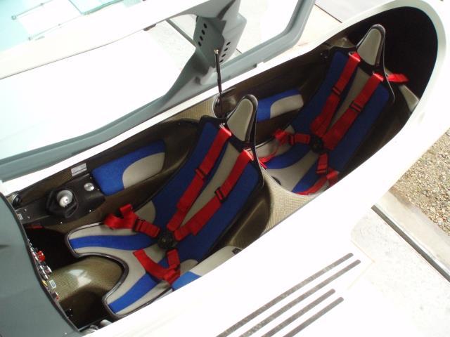
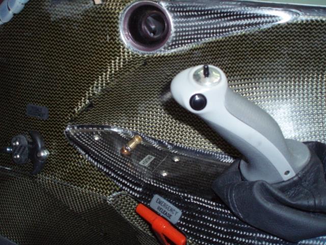
80 ARRANGEMENT Access to seats through right-side openable canopy Two composite height adjustable seats with adjustable headrests and pair of four-point safety belts. Dual control with two sidesticks on the right side, dual rudder control pedals connected with front wheel. Throttle lever and choke placed on left panel with engine cooling flap lever - usable in hot weather conditions. Main wheels are equiped by hydraulic brakes, controlled by the toe brakes placed on front pedals and parking brake. The front pedals are adjustable, ends of the unlocking cables are on the sides of the interior panel. Central brake lever for rear pilot is optional. Air vents are placed on the sides of instrument panel. Flaps control, undercarriage retracting control and propeller control panel are on left side of instrument panel. If propeller is hydraulic, controlling lever for both pilots is on side of throttle lever. Right side of instrument panel is used for backup instruments, GPS, 12V plug, starter, magnetos and master switches. Middle panel is used for EFIS (Dynon SKYVIEW, FLYMAP, Garmin), circuit breakers / switches. Radio and transponder are placed in the middle, or on side of EFIS screen, transponder is often controlled via EFIS screen. Trim switch, radio button and autopilot off button are placed on top of sidesticks. Fuel valve is placed on the left armrest behind the throttle. Indication of fuel amount is visible on EFIS/EMS display. In front of front sidestick is button controlling ventilation and heating. On middle panel and side panels of front seat there are red handles for emergency release of landing gear. Windows allowing to check properly locked gear struts are situated on the root of wings and on middle panel. Baggage compartment situated behind the rear seat is accessible from inside or from outside through lockable doors. Ballistic rescue system has 2 independent activation RED grips installed on the middle panel between pilot legs. Below armrests are small storage compartments. Optionally installed towing system with TOST lock has release handle on left panel. Small camera is installed in towing bracket. It displays rear view on the EFIS screen or on the aditional display. Page 7-14

81 REAR INSTRUMENT PANEL Rear instrument panel is part of cabine frame, optionally is equipped with EFIS/EMS screen connected to main device. Instructor configuration has also panel controlling flaps and landing gear. On the central panel are switches for engine start, magnetos, master switch. On the left panel is central brake lever. Optionally the slave radio control panel is installed. Page 7-15

 ATTENTION: This engine does not meet ICAO aviation standards (FAA, CAA).")
82 7.7. POWER UNIT ROTAX 912 ULS 100HP engine with electric starter, stainless steel exhaust with integral heating. Engine ROTAX type 912 ULS uncertified hp at 2380 RPM DESCRIPTION: 4-cylinder 4-stroke water / air cooled flat motor pressure lubrication with a separate 3 liter oil tank Fully equipped 912 ULS 3 DCDI - composite air distribution, alternator and airbox 2 CD carburetors mechanical diaphragm pump electronic double ignition electric starter integrated reducer I = (Optionally i = 2.43) ATTENTION: This engine does not meet ICAO aviation standards (FAA, CAA). Can be used in experimental and ultra-light airplane (Sport Flying Devices) only. Page 7-16
83 Technical data Performances for standard conditions (MSA/ISA). 912 ULS D.C.D.I. Engine Model Engine power 69,0 kw (95,0 hp) at 5500 RPM Max. 5 min.: 73,5 kw (100,0 hp) at 5800 RPM Torque 128 Nm at 5100 RPM Maximum speed 5800 RPM Bore: 84,0 mm Stroke: 61 mm Cilinder capacity: 1352,0 cm 3 Compression ratio: 10,5:1 Ignition: DUCATI double CDI Ignition timing: 4 to 1000 RPM / above 26 Sparking plugs: ROTAX part no Generator output: 250 W DC at RPM Voltage: 13,5 V OPERATING FILLING: Fuel: Olej: Natural 95 or AVGAS 100 LL API SF or SG, 100LL, not synthetic oil Coolant: 50% BASF Glysantin-Antikorrosion / 50% water WEIGHT- engine Standard engine with gearbox i=2,43 56,6 kg (124,8 lb.) Oil cooler ,5 kg Radiator ,0 kg Slip clutch 1,0 kg Fuel pump incl. pipes 0,2 kg Vacuum pump 0,8 kg External alternator 40 A/ 12 V DC 3,0 kg Rectifier 0,1 kg Page 7-17

84 7.8. PROPELLER Shark can be equipped by different propellers: DUC SWIRL Woodcomp SR WN Woodcomp KW20W Neuform TXR2-V-70-3 blade, on the ground adjustable - 2 blade, in flight electrically adjustable - 2 blade, in flight hydraulically adjustable - 2 blade, in flight electrically adjustable DUC SWIRL 3 blade, on the ground adjustable propeller, diameter 1680 mm Weight of this 3 blade propeller is 4,5 kg. It has carbon core, same as DUC FC WINDSPOON propeller, resistant to heavy loads. This propeller is simple, lightweight, robust, with a stainless steel leading edge. It achieves high cruising speeds, but it is less efficient during take-off. It is therefore not suitable for short grassland airports. Sheet settings are more laborious. Recommended angle is 24º. Page 7-18


85 Specification: Woodcomp SR W two blade in flight electrically adjustable propeller SR 3000/2 electically in flight adjustable propeller with two wood-composite blades, designed for Rotax 912 UL, Rotax 912 ULS and Rotax 914. Diameter is 1600 or 1700 mm. Blades angle is controlled electrically by servo mechanism and can be adjusted from minimum to maximum angle within approximately 8 second. Constant Speed unit: Control unit placed on instrument panel provides manual control of propeller constant speed mode. Page 7-19

86 PROPELLER BLADE DESIGN Propeller blade has wooden core, wrapped by several layers of carbon. Leading edge is made of durable plastic material providing mechanical protection Woodcomp KW 20W - two blade hydraulically in flight adjustable KW 20W has wood-composite blades, designed for Rotax 912 UL, Rotax 912 ULS and Rotax 914. Diameter is 1,7m. Propeller has identical blades and same performance as electrically adjustable SR W. Blades adjustment is controlled by hydrulic regulator using oil from engine lubrication system. Oil goes through hollow shaft in gearbox to the piston inside propeller hub. Regulator is controlled by lever placed on side of throttle. Page 7-20


87 Neuform TXR2-V-70 Neuform TXR2-V-70 is electrically or hydraulically in flight adjustable propeller with two composite blades. The blades are made of glass-fiber and are hollow. Root of blade is duralumin. Outside part of blade leading edge is casted of plastic material with improved resistance to abrasion. Servo controling the angle of the blades is located on the engine gearbox. Mechanical stops and micro switches of maximum and minimum angle of attack are situated on the servo brackets. The minimum angle of attack is set as mechanical stop by spacer rings during propeller assembly. Blade setup provides control unit FLYBOX. Page 7-21
88 7.9. RESCUE SYSTEM Shark is standardly equipped with ballistic rescue system Stratos/Junkers Magnum 501 with 2 independent release handles Description of rescue system Stratos/Junkers Magnum 501 Parachute canopy is pulled out by a specially designed rocket engine. The time required to launch is between seconds, depends on the type of system and air temperature. The rocket engine is placed in the rocket case. After the activation by activation handle the movement is mechanically transported by a bowden cable on a percussive device. It activates two percussion caps which ignit the rocket box. After ignition, the rocket escapes under high pressure from the rocket box, towing the rope which releases the cap of the parachute container, and the parachute is pulled out of the container. Then the bag of parachute is discarded and parachute canopy is filled with air. Technical data: Weight 9,65 kg 21,3 lbs Dimensions 360x245x200mm 14,2x9,7x7,9in Rocket engine Magnum 450 Area of parachute canopy 86 m sqft The number of ropes 32 Max. payload 475 kg 1050 lbs Max. speed 300 km/h 187 mph Repacking interval 6 years Burning time 0,6 sec. Total impulse at 20ºC 0,303 kns Mechanical double ignition Page 7-22


89 Minimum recommended flight level for system activation is 200 m. But there are known cases of successful application in less than 80 m. It also depends on the horizontal and vertical component of velocity. System lifetime is 18 years, if the revision and repackaging is performed every 6 years The activation mechanism Activation mechanism is made of cable with teflon coating and metal bowden. Activation handle has double safety mechanism to prevent accidental launch and lock mechanism for storage and transport. The mechanism is designed to have minimal activation forces under all circumstances. This minimal resistance remains throughout the life of the system. Page 7-23
90 Rescue system installation Rescue system is installed between firewall and canopy/instrument panel. Two front rescue system belts are hinged on the top of engine mounting hinges and are folded inside of rescue system box. Third belt is going under left cockpit frame to rear hinge, mounted on the top of baggage space frame. If the system is activated, the parachute cover is broken in defined places and the rear strip is ripped off the surface of the fuselage under the left edge of the cab frame. Page 7-24
91 7.10. TOWING SYSTEM Not installed. Page 7-25


92 7.11. POSITION LIGHTS Airplane can be optionally equipped by position and strobe lights. Lights are made of transparent material with integrated LED lights. Position lights (red, green and white LEDs) operate constantly. Lights are designed according to the regulations with defined angles and colours. Strobe lights blink. Left wing tip has red position light plus white strobe, right wing tip has green position light plus white strobe, on top of fin is white strobe, rudder has white position light plus white strobe. Strobe flashes are synchronized, three in a row and then break LANDING LIGHT Landing LEDs light can be optionally installed in NACA inlet. Page 7-26


93 7.13. ELT UNIT ELT unit is installed as option. The unit is attached on the bracket, behind the rear baggage frame. It is accessible through the cover of rear baggage frame. In cover is small window for easy ELT check. Antenna is placed on upper rear part of baggage frame and extended above the fuselage surface. Control panel of ELT is placed on instrument panel. Page 7-27

94 7.14. AUTOPILOT Airplane can be optionally equipped with an autopilot, mostly dual-axis. Control system is integrated in EFIS system - Dynon SkyView, FLYMAP, Garmin, or Oblo. Elevator servo is located behind baggage compartment rib. Aileron servo is located on right side in front of spar channel of fuselage. System is activated via separate ETA switch/fuse. The system is controlled and programmed through the EFIS display. Flight course can be inserted or planned route can be followed according to GPS coordinates. Autopilot deactivation buttons are located on both control levers. Servo of elevator Page 7-28
 - Remove flaps - Remove sealing tape from fuselage - root ribs gap -")
95 8. AIRPLANE HANDLING, CARE AND MAINTENANCE 8.1 WING DISMOUNTING Wing dismounting is an option for hangaring in a limited space or for transport. Wing disassemble The disassembly procedure consists of: - Flaps on position III (free access to pins on rear wing beam ) - Remove flaps - Remove sealing tape from fuselage - root ribs gap - Disconnect aileron controls below seat and flaps drive left and right - Unlock and dismount rear wing beam hinge pin - Unlock and dismount two main wing spar pins - Disconnect fuel hoses - Disconnect electric socket from fuel sensors - Disconnect pitotstatic hoses - Remove wing spar brackets from fuselage spar channel - Secure wings by using of hangar/transport jigs Remove flaps Before wings disassembly there is needed to remove flaps : Remove 3 bolts from flap hinges and one from control tube end in flap root rib. Page 8-1

 8.1.4.")
96 Disconnect aileron controls Disconnect aileron control rods below seats on left and right side Disconnect rear wing spar pin Unlock and dismount pins of rear wing SPAR. (accessible after flaps on) Disassemble the main wing spar pins Unlock and dismount both pins of main wing beam hinges (accessible from main undercarriage space) Page 8-2

97 Disconnect fuel hoses and fuel sensors sockets Remove wing spars out of center-wing With disconnected aileron and flaps control rods and free wing hinges, wing can be dismounted from centre wing box by pulling them out in the direction out of the airplane axis Disconnect pitostatic system hoses Disconnect pitostatic hoses before completely removing wing spar from spar channel of centre wing Secure wings by hangaring (transport) jigs Repeat the same procedure for second wing STABILIZER DISASSEMBLY Similar to wing it is possible to remove stabilizer as well: - Remove tape sealing gaps - Disconnect pushrods from elevator - Remove safety pin from rear bolt and remove castle nut - Disconnect connector from elevator trim servo - Move rudder on side - Pull stabilizer backward from pins and bearings Page 8-3
 Ground equipment: - cover of the pitot tube - securing set for mooring - fabric covers of canopy, wings or aircraft 8.3.2.")
98 8.3. PARKING AND MOORING General Always secure the airplane when parked. It is recommended to moor airplane in bad weather conditions or when it is left unattended (overnight etc.) Ground equipment: - cover of the pitot tube - securing set for mooring - fabric covers of canopy, wings or aircraft Cover of pitot tube Use cover of pitot tube while parking, as system protection against blowing air. Cover is provided with a red flag Mooring The airplane mooring set consists of the following: - 3 mooring bolts - 2 long and 1 short mooring cables - 2 wing bolts with M8 eye Mooring bolts should be screwed to the ground and the airplane should be moored by cables as shown below: Page 8-4
Pilot Operating Handbook - Merlin SSDR. TechPro Merlin. Pilot Operating Handbook
 TechPro Merlin Pilot Operating Handbook Aircraft type / version: Merlin Mk 1 Manufacturer: TechPro Aviation Serial no: 0012 Registration no: G-CIWL Date of publication: 20 JANUARY, 2016 This manual must
CARENADO COPYRIGHTS. Normal & Emergency Checklist
 NORMAL PROCEDURES CHECKLIST PREFLIGHT CHECK Control wheel -- RELEASE BELTS Avionics -- OFF Master Switch -- ON Fuel quantity gauges -- CHECK Master switch -- OFF Ignition -- OFF Exterior -- CHECK FOR DAMAGE
Jump to Table of Contents
 Jump to Table of Contents PIPER AIRCRAFT CORPORATION PA-28R-201, CHEROKEE ARROW III SECTION 3 EMERGENCY PROCEDURES 3.3 EMERGENCY PROCEDURES CHECK LIST ENGINE FIRE DURING
INDEX. Preflight Inspection Pages 2-4. Start Up.. Page 5. Take Off. Page 6. Approach to Landing. Pages 7-8. Emergency Procedures..
 INDEX Preflight Inspection Pages 2-4 Start Up.. Page 5 Take Off. Page 6 Approach to Landing. Pages 7-8 Emergency Procedures.. Page 9 Engine Failure Pages 10-13 Propeller Governor Failure Page 14 Fire.
JODEL D.112 INFORMATION MANUAL C-FVOF
 JODEL D.112 INFORMATION MANUAL C-FVOF Table of Contents I General Description...4 Dimensions:...4 Powertrain:...4 Landing gear:...4 Control travel:...4 II Limitations...5 Speed limits:...5 Airpeed indicator
CESSNA 182 CHECKLIST. LEFT WING Trailing Edge 1. Aileron CHECK freedom of movement and security
 CESSNA 182 CHECKLIST PRE-FLIGHT INSPECTION CABIN 1. Pilot s Operating Handbook AVAILABLE IN THE AIRPLANE (A.R.R.O.W.E) 2. Landing Gear Lever DOWN 3. Control Wheel Lock REMOVE 4. Ignition Switch OFF 5.
Flight Procedures Aero AT-3 R100
 Flight Procedures Page: 1 1. FOREWORD... 3 2. FLIGHT PREPARATION... 3 3. PRE-FLIGHT CHECK... 3 3.1. External inspection:... 4 3.2. In the cockpit... 4 3.3. Left wing... 5 3.4. Engine nacelle, canopy and
Com Active/Standby Frequency Switch. C om Active/Standby Frequencies. Terrain. Flight Plan. Button. Button
 ALABEO GNS530 Nav Active/Standby Frequency Switch Com Active/Standby Frequency Switch C om Active/Standby Frequencies Zoom In/Out Button Nav Active/Standby Frequencies On/Off Button Direct To Button Nav1
PA32-RT LANCE II CHECKLIST
 PA32-RT LANCE II CHECKLIST 6815.10.1112 1 Normal Procedures PREFLIGHT CHECK Control Wheel... RELEASE BELTS Parking brake... Set Master Switch... ON Fuel Quantity Gauges... check Master Switch... OFF Ignition...
Cessna 172P PPL Checklist Page 1
 Cessna 172P PPL Checklist 06-08-2017 Page 1 Cessna 172P PPL Checklist 06-08-2017 Page 2 Checklist Items Informational Items Critical Memory Items PREFLIGHT COCKPIT CHECK (DO-LIST) Pitot Cover -- REMOVE
Van s Aircraft RV-7A. Pilot s Operating Handbook N585RV
 Van s Aircraft RV-7A Pilot s Operating Handbook N585RV PERFORMANCE SPECIFICATIONS SPAN:..25 0 LENGTH...20 4 HEIGHT:.. 7 10 SPEED: Maximum at Sea Level...180 knots Cruise, 75% Power at 8,000 Ft...170 knots
Owners Manual. Table of Contents 4.1. INTRODUCTION SPEEDS FOR NORMAL OPERATION CHECKLIST & PROCEDURES 4
 NORMAL OPERATIONS Table of Contents 4.1. INTRODUCTION 2 4.2. SPEEDS FOR NORMAL OPERATION 2 4.3. CHECKLIST & PROCEDURES 4 4.3.1. PREFLIGHT INSPECTION 4 4.3.2. BEFORE STARTING ENGINE 8 4.3.3. STARTING ENGINE
Cessna 172RG WARNING. Maximum Demonstrated Crosswind. Takeoff or landing..15 KTS
 Cessna 172RG INTRODUCTION: This aircraft checklist contains information from the original manufacturer s Pilot Information Manual. Normal procedures associated with optional systems can be found in Section
TECNAM P2004 BRAVO N128LS
 TECNAM P2004 BRAVO N128LS GENERAL INFORMATION NORMAL PROCEDURES TIME SENSITIVE EMERGENCY TECNAM P2004 BRAVO CHECKLIST [FLIGHT PLAN DESIGNATION IS BRAV ] EMERGENCY CONTACT The following are First Landings'
F L I G H T M A N U A L
 LIMITED COMPANY AEROSPOOL PRIEVIDZA Airfield Prievidza 971 03 PRIEVIDZA Slovak Republic Fax: +421 46 51 83 250 Tel.: +421 46 51 83 200 aerospool@aerospool.sk www.aerospool.sk F L I G H T M A N U A L FOR
Aeroplanes DAR ltd. Brief Flight Manual DAR Solo BRIEF FLIGHT MANUAL. DAR-Solo series. Sofia Page 1 of 25
 BRIEF FLIGHT MANUAL DAR-Solo series Sofia 2015 Page 1 of 25 TABLE OF CONTENTS Introduction 3 Limitations and Safety Information 4 General View of DAR-Solo series 6 Ignition 7 Engine warm up 8 Taxiing 9
CZECH AIRCRAFT WORKS 1824, STARÉ , CZECH REPUBLIC
 CZECH AIRCRAFT WORKS Ltd. LU NÍ 1824, STARÉ M STO, 686 02, CZECH REPUBLIC Technical Commission of Light Aircraft Association of the Czech Republic represented by:... and as the organization authorized
FLASHCARDS AIRCRAFT. Courtesy of the Air Safety Institute, a Division of the AOPA Foundation, and made possible by AOPA Services Corporation.
 AIRCRAFT FLASHCARDS Courtesy of the Air Safety Institute, a Division of the AOPA Foundation, and made possible by AOPA Services Corporation. Knowing your aircraft well is essential to safe flying. These
PA28R ARROW CHECKLIST
 PA28R ARROW CHECKLIST 2300.11.0112 1 Normal Procedures Initial PREFLIGHT CHECK General Appearance... CHECKED Position & Taxi Path... CHECKED Tie Downs, Locks, Chocks & Covers... REMOVED Cockpit Controls...UNLOCKED
CIVIL AVIATION AUTHORITY SAFETY AND AIRSPACE REGULATION GROUP MICROLIGHT TYPE APPROVAL DATA SHEET (TADS) NO: BM-82 ISSUE: 2
 NO: BM-82 ISSUE: 2") TYPE: EV-97 Eurostar SL Microlight (1) MANUFACTURER: Light Sport Aviation Ltd, Wycombe Air Park, Hangar 1, Booker, Marlow, Buckinghamshire, SL7 3DP (2) UK IMPORTER: N/A (3) CERTIFICATION: BCAR Section
TYPE: EV-97 Eurostar SL Microlight (1) MANUFACTURER: Light Sport Aviation Ltd, Wycombe Air Park, Hangar 1, Booker, Marlow, Buckinghamshire, SL7 3DP (2) UK IMPORTER: N/A (3) CERTIFICATION: BCAR Section
PA WARRIOR II Quick Reference Handbook
 PA28-161 WARRIOR II Quick Reference Handbook Version 1.0 ALL GREY SHADED AREAS ARE MEMORY ITEMS Normal Procedures Pre-Flight Check... N-1 Before Start... N-3 Flooded Engine Start... N-4 Starting With
Vso 61. Vs1 63. Vr 70. Vx 76. Vxse 78. Vy 89. Vyse. 89 (blue line) Vmc. 61 (radial redline) Vsse 76. Va 134) Vno 163
 Vmc. 61 (radial redline) Vsse 76. Va 134) Vno 163") PA34-200T Piper Seneca II Normal procedures V-speeds Knots Vso 6 Vs 63 Vr 70 Vx 76 Vxse 78 Vy 89 Vyse Vmc 89 (blue line) 6 (radial redline) Vsse 76 Va 2-36(@4507lbs 34) Vno 63 Vfe 38 (0*)/2(25*)/07(40*)
PA34-200T Piper Seneca II Normal procedures V-speeds Knots Vso 6 Vs 63 Vr 70 Vx 76 Vxse 78 Vy 89 Vyse Vmc 89 (blue line) 6 (radial redline) Vsse 76 Va 2-36(@4507lbs 34) Vno 63 Vfe 38 (0*)/2(25*)/07(40*)
TECNAM P92 EAGLET N615TA TECNAM P92 EAGLET CHECKLIST [FLIGHT PLAN DESIGNATION IS ECHO ]
![TECNAM P92 EAGLET N615TA TECNAM P92 EAGLET CHECKLIST [FLIGHT PLAN DESIGNATION IS ECHO ]](/thumbs/86/93080937.jpg "TECNAM P92 EAGLET N615TA TECNAM P92 EAGLET CHECKLIST [FLIGHT PLAN DESIGNATION IS ECHO ]") TECNAM P92 EAGLET CHECKLIST [FLIGHT PLAN DESIGNATION IS ECHO ] EMERGENCY CONTACT The following are First Landings' emergency contact telephone numbers. We ask that you call the numbers in the order listed.
TECNAM P92 EAGLET CHECKLIST [FLIGHT PLAN DESIGNATION IS ECHO ] EMERGENCY CONTACT The following are First Landings' emergency contact telephone numbers. We ask that you call the numbers in the order listed.
AIRCRAFT OPERATING INSTRUCTIONS FOR LIGHT SPORT AIRCRAFT
 EVEKTOR - AEROTECHNIK a.s. Letecka 1384 Tel.: +420572 537 111 686 04 Kunovice Fax: +420 572 537 900 CZECH REPUBLIC email: marketing@evektor.cz FOR LIGHT SPORT AIRCRAFT Serial number: 2010-1306 Registration
PA-28R 201 Piper Arrow
 Beale Aero Club Aircraft Written Test PA-28R 201 Piper Arrow (Required passing score: 80%) 1. If an engine power loss occurs immediately after take off, the pilot s reaction should be to: a. maintain safe
State of Israel Ministry of Transport Civil Aviation Authority TYPE CERTIFICATE DATA SHEET
 State of Israel Ministry of Transport Civil Aviation Authority TYPE CERTIFICATE DATA SHEET TC number: Revision: Aircraft make: Aircraft model: IA298 New BRM Aero BRISTELL RG This Data Sheet which is part
Piper Archer II (PA )
") 1. Oil... 6-8 qts, Cap Secure CABIN 1. POH & Documents.. Check Available 2. Magneto Switch...... OFF 3. Pitot/Static Drains... Push to Drain 4. Avionics/Electrical Switches... OFF 5. Master Switch. ON
1. Oil... 6-8 qts, Cap Secure CABIN 1. POH & Documents.. Check Available 2. Magneto Switch...... OFF 3. Pitot/Static Drains... Push to Drain 4. Avionics/Electrical Switches... OFF 5. Master Switch. ON
Interior Pre Flight Documents: Check Control Wheel Lock: Remove Flight Controls: Check Instruments: Check for Damage Switches: Verify All Off Master
 Interior Pre Flight Documents: Check Control Wheel Lock: Remove Flight Controls: Check Instruments: Check for Damage Switches: Verify All Off Master Switch ALT/BAT: On Fuel Gauge: Check Quantity Flaps:
RFC Dallas, Inc. AIRCRAFT QUESTIONNAIRE (6/3/2018) "A Safe Pilot Knows His Equipment"
 A Safe Pilot Knows His Equipment") RFC Dallas, Inc. AIRCRAFT QUESTIONNAIRE (6/3/2018) "A Safe Pilot Knows His Equipment" NAME: Date: Aircraft: Bonanza Registration Number: Serial Number: The purpose of this questionnaire is to aid the pilot
RFC Dallas, Inc. AIRCRAFT QUESTIONNAIRE (6/3/2018) "A Safe Pilot Knows His Equipment" NAME: Date: Aircraft: Bonanza Registration Number: Serial Number: The purpose of this questionnaire is to aid the pilot
Pilot s Operating Handbook
 Pilot s Operating Handbook Airplane Registration Number: Airplane Serial Number: P100xxxx POH Copy Number: PiperSport Distribution Inc. Date of issue: 10/03/31 i Intentionally left blank Date of issue:
Owners Manual. Table of Contents 3.1. INTRODUCTION AIRSPEEDS FOR EMERGENCY OPERATION OPERATIONAL CHECKLISTS 3
 EMERGENCY PROCEDURES Table of Contents 3.1. INTRODUCTION 2 3.2. AIRSPEEDS FOR EMERGENCY OPERATION 2 3.3. OPERATIONAL CHECKLISTS 3 3.3.1. ENGINE FAILURES 3. ENGINE FAILURE DURING TAKEOFF RUN 3. ENGINE FAILURE
AIRSPEEDS. Cessna 172R Emergency Checklist
 AIRSPEEDS AIRSPEEDS FOR EMERGENCY OPERATION Cessna 172R Emergency Checklist INTRODUCTION This document provides checklist and amplified procedures for coping with emergencies that may occur. Emergencies
Cessna 182S-CHECKLIST PROCEDURES
 Cessna 182S-CHECKLIST PROCEDURES PREFLIGHT INSPECTION 1 CABIN 1. Pitot Tube Cover -- REMOVE (if installed) and check for stoppage 2. Pilot s Operating Handbook AVAILABLE IN THE AIRPLANE 3. Airplane Weight
N1523J CHECKLIST PA Nebraska Flight Center Eppley Airfield 3737 Orville Plaza Omaha, NE Tel. (402)
") CHECKLIST N1523J 1967 Cherokee 140 PA-28-140 F Nebraska Flight Center Eppley Airfield 3737 Orville Plaza Omaha, NE 68110 Tel. (402) 342-4314 www.nebflight.com Piper Cherokee 140 N1523J 1967 GENERAL INFORMATION
CHECKLIST N1523J 1967 Cherokee 140 PA-28-140 F Nebraska Flight Center Eppley Airfield 3737 Orville Plaza Omaha, NE 68110 Tel. (402) 342-4314 www.nebflight.com Piper Cherokee 140 N1523J 1967 GENERAL INFORMATION
FLIGHT MANUAL FOR ULTRALIGHT AEROPLANE
 FLIGHT MANUAL FOR ULTRALIGHT AEROPLANE U 15 Phoenix Registration: LN-YPV Serial number: 03/U15 Producer address: Lochmanova 64 562 01 Ústí nad Orlicí CZECH REPUBLIC www.phoenixair.cz 0. Table of Contents
I. DISPATCH PLANNING & AIRCRAFT EXTERIOR CHECK
 SCHODACK AVIATION Page 1 of 10 I. DISPATCH PLANNING & AIRCRAFT EXTERIOR CHECK 1. Flight Planning 1. Aircraft requirements & preparation: Required aircraft documents: Airworthiness Certificate Registration
I. DISPATCH PLANNING & AIRCRAFT EXTERIOR CHECK
 SCHODACK AVIATION Page 1 of 10 I. DISPATCH PLANNING & AIRCRAFT EXTERIOR CHECK 1. Flight Planning 1. Aircraft requirements & preparation: 1. Required aircraft documents: 1. Airworthiness Certificate 2.
N123AX Piper Saratoga II HP (PA-32R-301) Checklist (v23 - Revision 3 April 2011) AIRSPEEDS FOR SAFE OPERATIONS. Best Rate of Climb (gear up, flaps up)
 Checklist (v23 - Revision 3 April 2011) AIRSPEEDS FOR SAFE OPERATIONS. Best Rate of Climb (gear up, flaps up)") N123AX Piper Saratoga II HP (PA-32R-301) Checklist (v23 - Revision 3 April 2011) AIRSPEEDS FOR SAFE OPERATIS Best Rate of Climb (gear down, flaps up) Best Rate of Climb (gear up, flaps up) Turbulent Air
N123AX Piper Saratoga II HP (PA-32R-301) Checklist (v23 - Revision 3 April 2011) AIRSPEEDS FOR SAFE OPERATIS Best Rate of Climb (gear down, flaps up) Best Rate of Climb (gear up, flaps up) Turbulent Air
CHECKLIST 1969 CESSNA 172-K. NOTE: Verify all information with airplane's POH
 CHECKLIST 1969 CESSNA 172-K NOTE: Verify all information with airplane's POH PRE-FLIGHT INSPECTION 1 CABIN 1 A.R.R.O.W. CHECK Airworthiness Cert. In Clear View Registration In Clear View Radio License
PIPER CUB J3-65 N68952 PRE-FLIGHT CHECKLIST
 PRE-FLIGHT CHECKLIST COCKPIT Check airworthiness certificate, registration, weight & balance documentation Battery - CONNECTED Plug in headsets or secure as required Fuel ON Primer CLOSED & LOCKED Carb
PREFLIGHT CHECK COCKPIT RIGHT WING. NORMAL PROCEDURRES CHECKLIST PA-28RT 201 Arrow IV
 NORMAL PROCEDURRES CHECKLIST PA-28RT 201 Arrow IV PREFLIGHT CHECK COCKPIT Control Wheel -- Release Restraints Avionics -- OFF Parking Brake -- SET All Switches -- OFF Mixture -- IDLE CUT-OFF Master Switch
Preflight Inspection Cabin EMPENNAGE RIGHT WING Trailing Edge RIGHT WING NOSE
 Preflight Inspection Cabin 1. Control Wheel Lock REMOVED 2. Ignition Switch OFF 3. Avionics Power Switch OFF 4. Master Switch ON 5. Fuel Quantity Indicators CHECK QUANTITY 6. Master Switch OFF 7. Fuel
AIR TRACTOR, INC. OLNEY, TEXAS
 TABLE OF CONTENTS LOG OF REVISIONS... 2 DESCRIPTION... 4 SECTION 1 LIMITATIONS... 5 SECTION 2 NORMAL PROCEDURES... 8 SECTION 3 EMERGENCY PROCEDURES... 8 SECTION 4 MANUFACTURER'S SECTION - PERFORMANCE...
RFC Dallas, Inc. AIRCRAFT QUESTIONNAIRE (9/25/2016) "A Safe Pilot Knows His Equipment"
 A Safe Pilot Knows His Equipment") RFC Dallas, Inc. AIRCRAFT QUESTIONNAIRE (9/25/2016) "A Safe Pilot Knows His Equipment" NAME: Date: Aircraft: Cessna 182Q Registration Number: N631S Serial Number: The purpose of this questionnaire is to
RFC Dallas, Inc. AIRCRAFT QUESTIONNAIRE (9/25/2016) "A Safe Pilot Knows His Equipment" NAME: Date: Aircraft: Cessna 182Q Registration Number: N631S Serial Number: The purpose of this questionnaire is to
Checklist LN-DAG SFK 2014
 Checklist LN-DAG SFK 2014 2 GROUND Exsterior Checklist 1. Fuel (wings & filter) - Drained 2. Documents - Checked 3. Fire extinguisher, first aid sur. kit - Checked 4. Magnetos - Off 5. Master switch -
Phoenix S-LSA Glider 04/U15. Aircraft Operating Instructions
 Phoenix S-LSA Glider 04/U15 Aircraft Operating Instructions Table of Contents AIRCRAFT OPERATING INSTRUCTIONS 04/U15 Phoenix S-LSA Glider 0. Table of Contents... 1-4 1. Pilot operating handbook... 5 2.
Pilot s Operating Handbook. for. Airplane Serial Number: Airplane Registration Number: Type Certificate Number:
 Pilot s Operating Handbook Airplane Type: Model: Airplane Serial Number: for Airplane Registration Number: Type Certificate Number: Publication Number: SportStar RTC EASA.A.592 ERTC020-10-AS Date of Issue:
If, nonetheless, an emergency does arise, the guidelines given here should be followed and applied in order to clear the problem.
 3.1 INTRODUCTION 3.1.1 GENERAL This Chapter contains checklists as well as the description of recommended procedures to be followed in the event of an emergency. Engine failure or other airplane-related
Cessna 172 Skyhawk. Aircraft Checklist Models: R & S
 Cessna 172 Skyhawk Aircraft Checklist Models: R & S This is an abbreviated checklist. Most explanatory items, notes cautions and warnings have been omitted for brevity. Procedures in red/bold text in this
Expanded Flight Checklist Cessna 152
 OUTSIDE CHECK INSIDE CABIN 1 Magnetos... OFF 2 Mixture... IDLE CUT OFF 3 Master switch... ON 4 Fuel quantity... CHECKED 5 Master switch... OFF OUTSIDE CABIN 1 Left wing... CHECKED Surface condition Flap
QUICK REFERENCE HANDBOOK TECNAM P92 ECHO
 NORMAL LISTS PRE-START S Park brake Left fuel cock Flight Instruments (No broken glass or bent needles) Engine Instruments (No broken glass or bent needles) Right fuel cock Fuses Landing Light Avionics
INDEX: Normal Procedures Emergency Procedures Pre Flight Inspection NORMAL PROCEDURES BEFORE STARTING ENGINE
 INDEX: Normal Procedures Emergency Procedures Pre Flight Inspection NORMAL PROCEDURES BEFORE STARTING ENGINE 1. Preflight Inspection -- COMPLETE 2. Seats, Belts, Shoulder Harnesses -- ADJUST and LOCK 3.
FLIGHT MANUAL FOR SportStar MAX LIGHT SPORT AIRPLANE
 EVEKTOR - AEROTECHNIK a.s. Letecka 1384 Tel.: +420572 537 111 686 04 Kunovice Fax: +420 572 537 900 CZECH REPUBLIC email: marketing@evektor.cz FOR SportStar MAX LIGHT SPORT AIRPLANE Serial number: Registration
PA GURW (December 30, 2000) PRE-START. Langley Flying School. Airspeeds (MPH) for Safe Operation. Cockpit Checks
 PRE-START. Langley Flying School. Airspeeds (MPH) for Safe Operation. Cockpit Checks") Langley Flying School PA-34-200 GURW (December 30, 2000) Airspeeds (MPH) for Safe Operation V y (all weights) 105 V x (all weights) 90 En Route Climb 120 V mc 80 V yse 105 V xse 93 V r 80 V r (25 Flaps)
Langley Flying School PA-34-200 GURW (December 30, 2000) Airspeeds (MPH) for Safe Operation V y (all weights) 105 V x (all weights) 90 En Route Climb 120 V mc 80 V yse 105 V xse 93 V r 80 V r (25 Flaps)
Best Glide 75 kias (Max Gross)
") CESSNA 172XP CHECKLIST PREFLIGHT (Interior) 1. ACFT DOCS / INSPECTIONS--------CHECK 2. TACH TIME-----------------------------RECORD 3. CONTROL LOCK---------------------REMOVE 4. ELEVATOR / RUDDER TRIM------------
CESSNA 172XP CHECKLIST PREFLIGHT (Interior) 1. ACFT DOCS / INSPECTIONS--------CHECK 2. TACH TIME-----------------------------RECORD 3. CONTROL LOCK---------------------REMOVE 4. ELEVATOR / RUDDER TRIM------------
Flight Procedures. Viper SD-4. CAVOK Aviation Training Ltd.
 Viper SD-4 CAVOK Aviation Training Ltd. Page: 1 1. FOREWORD... 2 2. FLIGHT PREPARATION... 2 3. PRE-FLIGHT CHECK... 3 3.1. In the cockpit... 3 3.2. Left side of the fuselage... 4 3.3. Empennage... 5 3.4.
Phoenix S-LSA Glider 16/U15. Aircraft Operating Instructions
 Phoenix S-LSA Glider 16/U15 Aircraft Operating Instructions Table of Contents AIRCRAFT OPERATING INSTRUCTIONS 0. Table of Contents... 1-4 1. Pilot operating handbook... 5 2. General information... 6 2.1
DO NOT WRITE ON THIS TEST FEB 2013 Elmendorf Aero Club Aircraft Test. Cessna - 182
 DO NOT WRITE ON THIS TEST FEB 2013 Elmendorf Aero Club Aircraft Test Cessna - 182 For the following questions, you will need to refer to the Pilots Information Manual for the C-182R. The bonus questions
PA ARCHER II Quick Reference Handbook
 PA28-180 ARCHER II Quick Reference Handbook ALL GREY SHADED AREAS ARE MEMORY ITEMS 7813.03.0116 1 Table of Contents Normal Procedures... 4 PREFLIGHT CHECK... 4 BEFORE START... 6 FLOODED ENGINE START...
Pilot s Operating Handbook
 Pilot s Operating Handbook Airplane Registration Number: N4465F Airplane Serial Number: 08SC142 i Intentionally left blank ii aircraft is designed and manufactured by: Czech sport aircraft a.s. Na Záhonech
Pilot s Operating Handbook. for. Airplane Serial Number: Airplane Registration Number:
 Pilot s Operating Handbook Airplane Type: Model: Airplane Serial Number: for Airplane Registration Number: Type Certificate Number: Publication Number: SportStar RTC EASA.A.592 ERTC020-10-AS Date of Issue:
AEROPRO. A220 - taildragger
 AEROPRO CZ, Producer of Light Sport Aircraft Mladá 835, 687 25 Hluk, Czech Republic Pilot Operating Handbook and Flight Training Supplement AEROPRO A220 - taildragger Light Sport Aircraft Aircraft Type:
CIVIL AVIATION AUTHORITY TYPE APPROVAL DATA SHEET (TADS) NO: BM-84 ISSUE: 1
 NO: BM-84 ISSUE: 1") TYPE: SHERWOOD SCOUT (1) MANUFACTURER: The Light Aircraft Company Limited Hangar 4 Little Snoring Airfield Fakenham Norfolk NR21 0JL (2) UK IMPORTER: N/A (3) CERTIFICATION: BCAR Section S (Issue 6) (4)
TYPE: SHERWOOD SCOUT (1) MANUFACTURER: The Light Aircraft Company Limited Hangar 4 Little Snoring Airfield Fakenham Norfolk NR21 0JL (2) UK IMPORTER: N/A (3) CERTIFICATION: BCAR Section S (Issue 6) (4)
PIPER CUB J3-65 N68952 PRE-FLIGHT CHECKLIST COCKPIT
 PIPER CUB J3-65 N68952 PRE-FLIGHT CHECKLIST COCKPIT Check airworthiness certificate, registration, weight & balance documentation Battery - CONNECTED Plug in headsets or secure as required Fuel ON Magnetos
Checklist Robin DR40
 Flight Checklist for Normal Operations Massgebend ist das AFM (Parameters, Restrictions, Emergency, etc.) Jan 18 1 COCKPIT PREPARATION BEFORE STARTING ENGINE 1 Aircraft + Cockpit Inspection COMPLETED 1
NORMAL CHECKLIST ATTENTION!
 Avion Training CHECKLIST Normal Checklist CESSNA 172R / TC-STS Cessna 172 R TC-STS NORMAL CHECKLIST ATTENTION! DO NOT STOW THIS CHECKLIST IN DIRECT SUNLIGHT Avion Training - Doc.nr. 212 Revision 1 / 02022018
DA40 Diamond Star Systems Introduction AVIATION
 DA40 Diamond Star Systems Introduction AVIATION DA40 Systems Introduction What we ll look at... Airframe Flight Controls Landing Gear and Hydraulics Engine and Associated Systems Electric and Navigation
Aircraft Checklist Commander 114
 Aircraft Checklist Commander 114 This is an abbreviated checklist. Most explanatory items, notes cautions and warnings have been omitted for brevity. Procedures in red/bold text in this checklist should
NORMAL PROCEDURRES CHECKLIST PA T SENECA II PREFLIGHT CHECK INSIDE CABIN OUTSIDE CABIN
 NORMAL PROCEDURRES CHECKLIST PA-34-200T SENECA II PREFLIGHT CHECK INSIDE CABIN Avionics Master Switch -- OFF Landing Gear Control. -- DOWN Mixture Controls -- IDLE/CUTOFF Ignition Switches -- OFF Master
CESSNA 172N 08E/97E CESSNA 172N 08E/97E PREFLIGHT INSPECTION
 PREFLIGHT INSPECTION Visually check airplane for general condition during walk-around inspection. In cold weather, remove even small accumulations of frost, ice or snow from wing, tail and control surfaces.
Aircraft Checklist Cessna 182T
 Aircraft Checklist Cessna 182T This is an abbreviated checklist. Most explanatory items, notes cautions and warnings have been omitted for brevity. Procedures in red/bold in this checklist should be committed
LANCAIR LEGACY PRE-TEST FLIGHT INSPECTION (8-04)
") LANCAIR LEGACY PRE-TEST FLIGHT INSPECTION (8-04) OWNER PHONE # ADDRESS N SERIAL # AIRCRAFT TYPE DATE / / TACH TIME hrs. TOTAL TIME hrs. EMPTY WEIGHT CG. PAINT & INTERIOR? YES NO ENGINE TYPE PROPELLER ALL
LANCAIR LEGACY PRE-TEST FLIGHT INSPECTION (8-04) OWNER PHONE # ADDRESS N SERIAL # AIRCRAFT TYPE DATE / / TACH TIME hrs. TOTAL TIME hrs. EMPTY WEIGHT CG. PAINT & INTERIOR? YES NO ENGINE TYPE PROPELLER ALL
Flight Checklist for Normal Operations Massgebend ist das AFM (Parameters, Restrictions, Emergency, etc.)
") Flight Checklist for Normal Operations Massgebend ist das AFM (Parameters, Restrictions, Emergency, etc.) Jan18 1 COCKPIT PREPARATION BEFORE STARTING ENGINE 1 Aircraft + Cockpit Inspection COMPLETED 1
Flight Checklist for Normal Operations Massgebend ist das AFM (Parameters, Restrictions, Emergency, etc.) Jan18 1 COCKPIT PREPARATION BEFORE STARTING ENGINE 1 Aircraft + Cockpit Inspection COMPLETED 1
A E R O P R O s.r.o., Production of UL Planes. Dlhá 126, Nitra, Slovak Republic Tel./Fax: FLIGHT MANUAL AEROPRO EUROFOX
 A E R O P R O s.r.o., Production of UL Planes Dlhá 126, 949 07 Nitra, Slovak Republic Tel./Fax: +421 37 6526355 FLIGHT MANUAL AEROPRO EUROFOX Aircraft Name - Type: EuroFOX 912 in version: AEROPRO EuroFOX
Elmendorf Aero Club Aircraft Test
 DO NOT WRITE ON THIS TEST FEB 2014 Elmendorf Aero Club Aircraft Test Cessna - 185 For the following questions, you will need to refer to the Pilots Information Manual for the C-185F and Graphic Engine
GACE Flying Club Aircraft Review Test 2018 N5312S & N5928E. Name: GACE #: Score: Checked by: CFI #:
 GACE Flying Club Aircraft Review Test 2018 N5312S & N5928E Name: GACE #: Score: Checked by: CFI #: Date: (The majority of these questions are for N5312S. All N5928E questions will be marked 28E) 1. What
CIVIL AVIATION AUTHORITY OF THE CZECH REPUBLIC
 CIVIL AVIATION AUTHORITY OF THE CZECH REPUBLIC 69-04 Revision 6 MORAVAN-AEROPLANES a.s. Model Z 526 F 11.04.2007 TYPE CERTIFICATE DATA SHEET No. 69-04 This data sheet which is a part of Type Certificate
Test Flying should only be performed by a pilot who is licensed, rated and experienced on the aircraft type.
 Test Flying Procedure: Test Flying should only be performed by a pilot who is licensed, rated and experienced on the aircraft type. In particular, the test pilot should have recently demonstrated an ability
CESSNA 172I CESSNA 172I PREFLIGHT INSPECTION
 PREFLIGHT INSPECTION Visually check airplane for general condition during walk-around inspection. In cold weather, remove even small accumulations of frost, ice or snow from wing, tail and control surfaces.
KR-030 TOPAZ AIRPLANE
 Section 0 General PILOT S OPERATING HANDBOOK KR-030 TOPAZ AIRPLANE AIRPLANE REGISTER NUMBER: AIRPLANE SERIAL NUMBER: 30 -... -... EDITION: 1 JULY 2010 0-1 Section 0 General 0.1 LOG of REVISIONS Any revisions
V - Speeds. RV-10 V fe Flaps Speeds Trail (0 deg) Half (15 deg) Full (30 deg) 122 kias 96 kias. 80 kias
 Half (15 deg) Full (30 deg) 122 kias 96 kias. 80 kias") RV-10 Check List V - Speeds RV-10 V fe Flaps Speeds Trail (0 deg) Half (15 deg) Full (30 deg) 122 kias 96 kias 87 kias V s1 Stall (Flap Up) 60 kias V s0 Stall (Flap 40 deg) 55 kias Best Glide 80 kias V
RV-10 Check List V - Speeds RV-10 V fe Flaps Speeds Trail (0 deg) Half (15 deg) Full (30 deg) 122 kias 96 kias 87 kias V s1 Stall (Flap Up) 60 kias V s0 Stall (Flap 40 deg) 55 kias Best Glide 80 kias V
OE-AFG KATANA DV 20 BORDEXEMPLAR
 PREFLIGHT PROCEDURES Operator: Fliegergruppe Wien im österreichischen AERO- Club A -2540 Flugplatz Bad Vöslau www.fliegergruppe.at OE-AFG: BJ. 1994 WerkNr: 20071 Eingebaut am 10.4.2006 in Hofkirchen Motornummer:
THIS MANUAL TO BE KEPT IN AIRCRAFT. NG4-LSA
 THIS MANUAL TO BE KEPT IN AIRCRAFT. NG4-LSA AEROSPORT AVIATION PTY LTD, MELBOURNE, AUSTRALIA. REGISTRATION 24-7357 SR No. 001/2008 ROKO AERO A.S. VĚTRNÁ 1604, 688 01 UHERSKÝ BROD, CZECH REPUBLIC phone.:
Changed links from specific to general to account for ever-changing and broken links.
 Flight Training Supplement FTS page iii REV 1: Added the following note to the table of contents "NOTE: Pages 4-7 4-9, 5-7, 5-9, 6-3 and 6-5 correspond to a particular EFIS installation. Please remove
4A.2 AIRSPEEDS FOR NORMAL OPERATING PROCEDURES
 Normal Operating DA 40 AFM 4A.1 INTRODUCTION Chapter 4A contains checklists and describes extended procedures for the normal operation of the airplane. 4A.2 AIRSPEEDS FOR NORMAL OPERATING PROCEDURES Flight
FM-250 Vampire Flight Manual
 FM-250 Vampire Flight Manual Flight Manual Page 0 of 40 TABLE OF CONTENTS SECTION 1. General 2. Limitations 3. Normal Procedures 4. Emergency Procedures 5. Performance 6. Airplane Handling, Service & Maintenance
Cessna 152 Checklist
 Cessna 152 Checklist This checklist covers the operation of the model 152. Use at your own risk, the author nor the publisher is responsible for any damage or accidents resulting from the use of this checklist.
PA , Model E Normal Checklist (04/15/11)
") PA-23-250, Model E Normal Checklist (04/15/11) Key Airspeeds IAS-MPH V NE 249 V NO 198 V LO/LE 150 V A (At max gross weight.) 149 Speed for single engine cruise. 138 V FE Quarter Flaps 160 Half Flaps 140
PA-23-250, Model E Normal Checklist (04/15/11) Key Airspeeds IAS-MPH V NE 249 V NO 198 V LO/LE 150 V A (At max gross weight.) 149 Speed for single engine cruise. 138 V FE Quarter Flaps 160 Half Flaps 140
Pilot operating handbook. EuroFOX Aviation. EuroFOX
 EUROFOX AVIATION, The hangar, Wanshurstgreen Farm, Battle lane, Marden, Kent, TN12 9DF EuroFOX Aviation is a trading name of Ascent industries Ltd. Company registration nr 7731403 Pilot operating handbook
Tie down IAS-TAS Table 14
 PA28-161- 1 Piper PA28-161 Archer II Cockpit Interior Exterior Check Exterior Check [cont.] Before Start Engine Start After Start ENG Flooded Start Start with External Pwr Run-Up Before Takeoff Short Field
DEPARTMENT OF TRANSPORTATION FEDERAL AVIATION ADMINISTRATION TYPE CERTIFICATE DATA SHEET NO. A13CE
 DEPARTMENT OF TRANSPORTATION FEDERAL AVIATION ADMINISTRATION A13CE Revision 28 CESSNA 177 177A 177B November 16, 2010 TYPE CERTIFICATE DATA SHEET NO. A13CE WARNING: Use of alcohol-based fuels can cause
Flight Manual. Manufacturer : Tomark s.r.o, Strojnícka 5, Prešov 08001, Slovakia
 Flight Manual Manufacturer : Tomark s.r.o, Strojnícka 5, Prešov 08001, Slovakia Type : Viper SD - 4 Model : UL Serial number : 0042 Aircraft registration : Category : Manufacturer : Aircraft conforming
2010 Airborne Aviation Pty Ltd
 Aircraft Information Booklet Pitts S-2C VH-JAX Last revised: 10 September 2010 2010 Airborne Aviation Pty Ltd www.airborne-aviation.com.au THIS PAGE INTENTIONALLY LEFT BLANK Contents Aircraft Overview
USAF Aero Club T-41B (Cessna R-172E) Aircraft Exam Updated February 2017
 Aircraft Exam Updated February 2017") USAF Aero Club T-41B (Cessna R-172E) Aircraft Exam Updated February 2017 Instructions Complete the supplement following exam using the answer sheet provided. Do not assume information not specifically
USAF Aero Club T-41B (Cessna R-172E) Aircraft Exam Updated February 2017 Instructions Complete the supplement following exam using the answer sheet provided. Do not assume information not specifically
Flight Manual DG-300. No. page description issue date. 2 4, 17, 21, 33 Installation of an additional tow hook TN Oct. 85
 Flight Manual DG-300 Manual amendments No. page description issue date 1 1, 2, 4-6, 8, 10- amendments and corrections TN 359/7 May 85 12, 15, 16, 19, 21, 22, 24, 25, 28, 30, 31, 33 2 4, 17, 21, 33 Installation
CESSNA 172S NAV III VFR CHECKOUT POH EXAMINATION (Based on N1129K, serial no. 172S revised 10/05/06)
") INTRODUCTION, POH CESSNA 172S NAV III VFR CHECKOUT POH EXAMINATION (Based on N1129K, serial no. 172S10315 - revised 10/05/06) 1. Rate of climb at sea level: 2. Service ceiling: 3. Takeoff performance,
INTRODUCTION, POH CESSNA 172S NAV III VFR CHECKOUT POH EXAMINATION (Based on N1129K, serial no. 172S10315 - revised 10/05/06) 1. Rate of climb at sea level: 2. Service ceiling: 3. Takeoff performance,
CIVIL AVIATION AUTHORITY SAFETY REGULATION GROUP MICROLIGHT TYPE APPROVAL DATA SHEET (TADS) NO: BM 41 ISSUE: 7
 NO: BM 41 ISSUE: 7") TYPE: Shadow Series CD (1) MANUFACTURER CFM Aircraft Ltd (ceased trading) BMAA is responsible for continued airworthiness (2) UK IMPORTER None (3) CERTIFICATION BCAR Section S (First example Advanced Issue
TYPE: Shadow Series CD (1) MANUFACTURER CFM Aircraft Ltd (ceased trading) BMAA is responsible for continued airworthiness (2) UK IMPORTER None (3) CERTIFICATION BCAR Section S (First example Advanced Issue
Flight checklist for normal operations Massgebend ist das AFM (parameters, restrictions, emergency, etc.)
") JAN13 1 Flight checklist for normal operations Massgebend ist das AFM (parameters, restrictions, emergency, etc.) Cockpit preparation before starting engine 1 Aircraft + Cockpit inspection completed (according
JAN13 1 Flight checklist for normal operations Massgebend ist das AFM (parameters, restrictions, emergency, etc.) Cockpit preparation before starting engine 1 Aircraft + Cockpit inspection completed (according
M20J-201 Checklist BEFORE STARTING ENGINE
 M20J-201 Checklist BEFORE STARTING ENGINE Preflight... COMPLETE Baggage door... LATCHED/LOCKED Door... LATCHED/LOCKED Seatbelts... FASTENED Passenger brief....... [seatbelts/exits/smoking/talking/traffic]
Elmendorf Aero Club Aircraft Test
 DO NOT WRITE ON THIS TEST FEB 2013 Elmendorf Aero Club Aircraft Test Cessna - 182 For the following questions, you will need to refer to the Pilots Information Manual for the C-182R. The bonus questions