CABLE LADDERS CATALOGUE
|
|
|
- Robert Boone
- 5 years ago
- Views:
Transcription


1 CABLE LADDERS CATALOGUE
2 CONTENT
3 INTRODUCTION 5 TECHNICAL INFORMATION 13 CABLE LADDER TRAY OVERVIEW 47 ALUMINUM LADDERS 57 STEEL LADDERS 65 LADDER FITTINGS 83 LADDER TYPE ACCESSORIES 89 FIXING ACCESSORIES SYSTEM 95 SUPPORT SYSTEMS 101 HEAVY DUTY SYSTEMS 111 FIRESTOP SYSTEMS 129 HOW TO ORDER 135 LOCATIONS 139
4 01
5 INTRODUCTION


6 Companies Profile IKK Group of Companies The IKK Group is a major business institution, serving most of the Arab World in the Industrial, Construction and Trading fields as well as in Specialized Maintenance and Services. After almost four decades in the business, the IKK Group has become one of the leading enterprises in the region with focus on the Construction Industry in general. The IKK Group operates through 200 divisions, branches and outlets, spread over 16 countries, covering all major cities in the region and employing over 12,000 employees. 6 Introduction

7 UNITECH For Building & Construction Materials Unitech for Building and Construction Materials, a member of the IKK Group of Companies was established in 1979 in Saudi Arabia. A Solutions Provider company, specialized in the: Design /Manufacturing and Trading of Building and Construction Materials. As a declaration of its commitment to quality, the company implemented the Quality Management concept, and has acquired the ISO 9001:2008 Quality Management System, in addition to being a member of the U.S.Green Building Council (USGBC). UNI-METAL - Constructions Steel Products clamps & hangers, block ladders, dry wall and ceiling accessories, cable management systems: cable trays, cable ladders, cable trunkings, basket trays, cable supports: steel lintels and block work accessories. are spread among various cities in the MENA region; KSA, UAE, Lebanon, Jordan, Libya, Oman, Bahrain, Egypt, SFSP - Specialized Factory for Steel Products through a variety of products and through its geographical presence. Production at the factory is observed to international standards of fabrication. SFSP has manufacturing facilities in KSA, UAE, Egypt & Lebanon. SFSP adapts quickly and easily to the market demands and requirements. Quality at SFSP is uncompromised; the factories have been able to acquire ISO 9001: 2008 in Jeddah in Saudi Arabia, Sigma Factory for Steel Products in Ajman in UAE, in addition to ISO 14001: 2004 in the 6th of October City in Egypt


8 SFSP - KSA SFSP / Kingdom of Saudi Arabia Specialized Factory for Steel Products 3rd Industrial City Jeddah Tel: , Fax: sfsp.jeddah@ikkgroup.com Specialized Factory for Steel Products - Khumra / Jeddah Tel : Fax: sfsp.jeddah@ikkgroup.com T C A F 6 S E I OR SFSP / UAE SIGMA Factory for Steel Products DIC (Dubai Industrial City) Tel : Fax: sfsp.dic@ikkgroup.com SFSP / EGYPT Specialized Factory for Steel Products - 6th of October City, Cairo Tel : , Fax: sfsp.cairo@ikkgroup.com SFSP / LEBANON Specialized Factory for Steel Products / s.a.r.l - Tanayel, Bekaa Tel: Fax: sfsp.lebanon@ikkgroup.com


9 ISO Certificates Products Uni-Metal Cable Trays - Ladder type, fittings and accessories from SFSP are manufactured in compliance with international standards. Uni-Metal provides a wide range of products capable of providing the characteristics which respond to the proposed application, along with quality of assembly, speed of installation and cost-saving cable Trays. 9


10 SFSP SFSP Is a leading manufacturer and fabricator of steel and aluminum products used for the support of equipment in industrial, commercial, utility and OEM installations. Our customers have access to the most complete support systems offered in the industry including metal framings, cable management systems, pipe hangers, slotted angles, fasteners and others. (Our factory is equipped with an in-house hot-dip galvanization facility). 10 Introduction


11 CNC Machines Roll Forming Machine Design Office- GERMANY 11
12 02
13 TECHNICAL INFORMATION
14 MATERIALS AND FINISHES Materials Aluminum G.Aluminum 6063 T6 Mild Steel - Plain A. Hot Rolled Steel Plates, Sheets and Coils S235 JR as per: EN / DIN / BS 4360 / ASTM A 653M / ASTM A 1011 / ASTM A a JIS 3101 / JIS 3106 / GB 700 / GB / T1591. ASTM A 907 / ASTM A 1018M. ASTM A 570M / ASTM A 572M. B. Cold Rolled Steel DC 01, as per: EN / DIN 1623, Part 2 / BS 1449:1 / ASTM A366 / ASTM A 1008 / JIS G 3141 / GB 699. EN / ASTM A 568M Mild Steel - Galvanized C. Continuously Pre- Galvanized Hot Dip Zinc Coated Steel DX 51D + Z as per: EN / DIN / BS 2989/ ASTM A 527M / ASTM A 653M / JIS G EN 10326/ EN / ASTM A 526, 527, 528/ ASTM A 146 D. Electro Galvanized Steel (Electrolytic Coating) DC01 + ZE v as per: EN / DIN / ASTM A591 / JIS G 3313 / JIS G 3141/BS 1449:1 EN Stainless Steel F.Austenitic Stainless Steels SS 304 & SS 316, as per: ASTM A 240 /EN / DIN / BS 1449:2 / ASTM A480 / ASTM A666 / ISO 3506 / EN /JIS G 4304 F.1 Stainless Steel Fasteners EN 3506 F.2 Stainless Steel Wire BS 1554,ASTM A276 Finishes 1- Hot DIP Galvanization after Fabrication as per: ASTM A 123 / ASTM A 153 / ISO BS 729 / DIN Zinc Electroplating after Fabrication as per: ASTM B633 / EN / ISO 4042/ BS 1706 / BS 3382 / DIN Powder Coating Epoxy / Polyester / Epoxy & Polyester BS 3900 / ISO 2409 / ISO 1519 / ISO Introduction
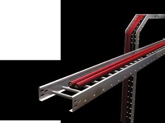
15 PRODUCTS RANGE The different types of tray designs are described below: Ladder (Cable Ladder) Swaged rounded tubular (Aluminum or Steel) or welded c-channel (steel). A prefabricated metal structure consisting of two side rails connected by individual transverse embers or rungs. Cable Ladder Trays are the most common and the most economical types of trays. They also provide maximum ventilation for cabling. Swaged Rounded Tubular Welded C-Channel Trough A prefabricated metal structure with clear openings no greater than 4 (100mm). Trough Cable Trays are the best choice for smaller cables. Ventilated troughs offer some air-flow while completely eliminating cable sagging. Ventilated Bottom Solid Bottom Perforated Cable Tray (Cable Trays) A prefabricated metal structure consisting of a bottom with openings within the cable bearing surface. Solid bottom Cable Trays completely eliminate cable sagging and offer maximum protection for the cables. Wire Mesh (Basket Tray) Is ideally suitable for light - to medium-duty commercial and industrial applications where space is at a premium. SFSP wire Basket Trays have a fast connection profile for installations requiring long runs of straight Cable Trays lengths. Applications : Network cabling, wiring closets, fiber-to-desktop applications and can often be used in suspended ceiling plenum areas and under computer room flooring. Channel (Cable Trunking) A prefabricated metal structure consisting of a one-piece solid bottom channel section not exceeding 6 (150mm) in width. 15
16 Specialized Factory for Steel Products (Jeddah/KSA) Sigma Factory for Steel Products (Ajman & Umm Al Quwain /UAE) Specialized Factory for Steel Products (6th of October/Egypt) Specialized Factory for Steel Products - (Bekaa /Lebanon) UNI-METAL Cable Ladder Tray Systems, fittings and accessories from SFSP are manufactured in compliance with : - IEC International Electrotechnical Commission (Cable management Cable tray systems and cable ladder systems) - SASO IEC (61537/2007) Saudi Standard (Cable management Cable tray systems and cable ladder systems) - NEMA VE National Electrical Manufacturers Association. (Metal Cable Tray Systems) - NEMA VE1 class 20 C - NEMA VE National Electrical Manufacturers Association. (Metal Cable Tray Installation Guide Lines) - NEC (ANSI / NFPA 70) National Electric Code (Metal Cable Tray Guide Lines) 16 Technical Information
17 UNI-METAL Cable Ladder Tray Systems are designed to meet most requirements of cable and electrical wire installations and comply to local and international standards of fabrication and finishing. Cable Ladder Systems are economical wire and cable management systems designed to support and protect electrical wires and cables. National Electric Code (NEC) permits Cable Ladder in a wide variety of indoor and outdoor applications. The NEC also permits Cable Ladder for use as equipment ground conductor. Cable Ladder Systems can provide significant advantages in cable filling over other wiring methods. This can provide savings in the size or number of raceways required, thereby, reducing both material and labor costs. In many cases, NEC permits greater conductor ampacities in Cable Ladder Systems than for other wiring methods. Under certain conditions, the NEC allows Free Air rating of large, single conductor power cables (4/0 & larger) in ventilated Cable Ladder Systems. This can provide significant savings in conductor costs. Cable Ladder permit much greater spacing between support hangers than most other systems, providing savings in support costs and installation labor. 17
18 TECHNICAL INFORMATION ACCORDING TO IEC STANDARD Product under IEC standard are in compliance with the requirement of the European directive. This standard specifies the requirements for: - Installation - Load testing - Classification - Marking, dimensions - Electrical Continuity MATERIAL: Flame spreading resistance: Electrical Conductivity Characteristics Electrical Continuity Characteristics METALLIC: Non Flame Spreading With Conductivity With Continuity SFSP products meet electrical continuity requirement: Resistance 5 milli Ohm/mm without couplers Resistance 50 milli Ohm with splice plate Splice Plate The system components are designed to withstand. The stress likely to occur during recommended transport and storage. Cable tray system and cable ladder systems according to IEC are not intended to be used for human support. Table 1 Classification for resistance against corrosion Class Reference - Material and Finish 0 a None 1 Electroplated to a minimum thickness of 5 µm 2 Electroplated to a minimum thickness of 12 µm 3 Pre-galvanised to grade 275 to EN and EN Pre-galvanised to grade 350 to EN and EN Post-galvanised tp a zinc mean coating thickness (minimum) of 45 µm according to ISO 1461 for zinc thickness only 6 Post-galvanised tp a zinc mean coating thickness (minimum) of 55 µm according to ISO 1461 for zinc thickness only 7 Post-galvanised tp a zinc mean coating thickness (minimum) of 70 µm according to ISO 1461 for zinc thickness only 8 Post-galvanised tp a zinc mean coating thickness (minimum) of 85 µm according to ISO 1461 for zinc thickness only (usually high silicon steel) 9A Stainless steel manufactured to ASTM: A 240/A 240M - 95a designation S30400 or EN grade without a post-treatment b 9B Stainless steel manufactured to ASTM: A 240/A 240M - 95a designation S31603 or EN grade without a post-treatment b 9C Stainless steel manufactured to ASTM: A 240/A 240M - 95a designation S30400 or EN grade with a post-treatment b 9D Stainless steel manufactured to ASTM: A 240/A 240M - 95a designation S31603 or EN grade with a post-treatment b a For materials which have no declared corrosion resistance classification b the post - treatment process is used to improve the protection against crevice crack corrosion and the contamination by other steels. 18 Introduction
19 Table 2 Minimum temperature for the system component as given in table 2 Minimum Temperature Classification Minimum transport, storage, installation and application temperature ºC Table 3 Maximum temperature for the system component as given in table 3 Maximum Temperature Classification Maximum transport, storage, installation and application temperature ºC Table 4 Perforation base area Classification Classification Perforation in the base area A up to 2% B over 2 % and up to 15 % C over 15 % and up to 30 % D More than 30 % NOTE Classification D relates to IEC , Sub clause A , second paragraph Table 5 Free base area classification (Cable Ladder Length) Classification Free base area X up to 80% Y over 80 % and up to 90 % Z More than 90 % NOTE Classification Z relates to IEC , Sub clause A , third paragraph Table 6 Table 7 Class Zinc coating thickness of reference materials Minimum Thickness Minimum coating thickness as given in EN or EN Mean coating thickness (minimum) to ISO 1461 µm µm µm 0a As declared by the manufacturer or responsible vendor Salt spray test duration Class (as detailed in Table 1 Duration h
20 TECHNICAL INFORMATION ACCORDING TO IEC STANDARD Products covered by this standard are, in normal use, passive in respect of electromagnetic influences, emission and immunity. NOTE: When products covered by this standard are installed as part of a wiring installation, the installation may emit or may be influenced by electromagnetic signals. The degree of influence will depend on the nature of the installation within its operating environment and the apparatus connected by the wiring. Power supply cables and signal cables can share the same cable conveyance systems (Trays, Channels, Etc.) Adequate seperation need to be provided (by distance or shielding) between power cables and signal cables. Power cables and signal cables need to be cross at right angles. In order to prevent disturbances, the minimum seperation between power cables and signal cables depends on many factors, such as following: a) The level of immunity from the various electromagnetic interferance (surges, overcurrents, lighting impulses, ring waves, continuous waves, ect.) of the equipment connected to the signal cabling system. b) The connection of the equipment to the grounding system. c) The local electromagnetic environment (the simultaneous appearance of disturbances: for example, harmonics added to discharges and to continuous waves). d) The electromagnetic spectrum. e) The distances that the cables run parallel to each other (the coupling zone). f) The kind of cable. g) Cable attenuation against coupling. h) The quality of the connections between the connectors and the cable. f) The type of cable conveyance system and its accessories. Seperation between signal cabling and power cabling Distance Type of installation Unshielded power cable and Unshielded signal cable Unshielded power cable and shielded signal cable (2) shielded power cable and Unshielded signal cable shielded power cable and shielded signal cable Without a dividing wall or with a non metal divider (1) 200 mm 50 mm 30 mm 0 mm Aluminum divider 100 mm 20 mm 10 mm 0 mm Steel divider 50 mm 5 mm 2 mm 0 mm 1) It is assumed that in the event of a metal divider, the design of the cable conveyance system will provide shielding attenuation that is approximate to the material used in the divider. 2) Shielded signal cables have to be comply with the EN series. 20 Introduction
, additional connections to the ground systems are recommended at irregular intervals. All ground should be a short as possible.")

21 Metal systems for cable conveyance: trays, channels, etc. Metal systems for cable conveyance should always be connected to the local ground at both ends. Over long distances (more than 50 m), additional connections to the ground systems are recommended at irregular intervals. All ground should be a short as possible. Ground and equipotentiel connections Overview, the basic purposes of connection and grounding applicable to unshielded and shielded wiring systems are as follow: - Safety: to limit contact voltage and provide a return path in the event of a fault to ground; - EMC: to have zero potential and equipotentiality, which provide a shielding effect. 21
22 TECHNICAL INFORMATION ACCORDING TO IEC STANDARD 1. Terms and definition: 1.1 Cable tray system or cable ladder system assembly of cable supports consisting of cable tray lengths or cable ladder lengths and other systems components. 1.2 System Component Parts used with in the system components are as follows: a) Cable tray length or cable ladder length b) Cable tray fitting or cable ladder fitting c) Support device d) Mounting device e) System accessory 1.3 Fitting System component used to join, change direction, change dimension or terminate cable tray length (couplers, bends, tees, crosses). 1.4 Support device System component designed to provide mechanical support and which may limit movement of cable runway. 1.5 Mounting device System component used to attach or fix other devices to the cable runway. 1.6 Internal fixing device Device for joining and for fixing system components to other system components. 1.7 External fixing device Device used for fixing a support device to walls, ceiling or other structural parts. 2. Mechanical properties: 2.1 Mechanical strength: SFSP cable tray systems and cable ladder systems provide adequate mechanical strength. The SWL (safe working load) has been tested.the load has been increased to 1.7 times the SWL (according to IEC). 3. Electrical properties: 3.1 Electrical continuity Cable tray system and cable ladder systems have adequate electrical continuity to ensure equipotential bonding and connections to earth. 3.2 Electrical non-conductivity Cable tray system components and cable ladder system components have been declared electrically non conductive. An overall accuracy of surface resistance has been guarantee: surface resistivity= Rx X p/g = surface resistivity in Ohm, Rx = Measured surface Resistance, P = twice the width of cable tray (mm), g = Distance between electrodes in mm. All necessary information for a proper and safe installation and use of the cable tray system and cable ladder system has been provided. The safe working load and impact resistance is valid for the whole temperature declared. The information include: a) Instructions for the assembly and installation of system components and for the precautions required to avoid excessive transverse deflection which could cause damage to the cables. Transverse deflection: Vertical deflection across the width of the base area, omitting the longitudinal deflection, when mounted horizontally. The transverse deflection of each span at the safe working load shall not exceed 1/20th of the cantilever. Mid-Span deflection: The practical mid-span deflection as SWL shall not exceed 1/100th of the span. If the span is greater than the cable tray length or cable ladder the joint shall be placed at min span. 22 Introduction
23 Cable LADDER systems Product footprint Cable ladder accessory foot print standard radius is 300 mm. 90 Degree Flat Bend Crossover Equal Tee Unequal Tee Outside Riser Central, right, or left hand reducer Footprints are identical for all ranges 23


24 NEMA VE1 / Selection Process The following factors shall be considered when determining the appropriate Cable Trays Systems: Materials and Finishes Types of Cable Trays NEMA Classification NEMA Classes Cavity Size Load Depth/Width of Tray Lengths of Straight Sections Radii of Fittings Cable Tray Support Locations Electrical Grounding 24 Technical Information
25 NEMA CLASSIFICATION The National Electrical Manufacturers Association (NEMA VE-1) USA, classifications for Cable Trays were established to simplify and standardize the specifications of Cable Trays. This classification is based on the working load (the total weight of the cables), and the support span (the distance between supports). Cable Load/Working Load The Cable load or the working load is the total weight of the cables to be placed in the tray. The NEMA classes are based on cable loads of 50Lbs/Ft., (74 kg/m), 75Lbs/Ft. (112 kg/m), and 100Lbs/Ft. (149 kg/m). This is the total weight of cables in the tray. For purposes of selecting a suitable tray, this weight shall be rounded off to the next higher NEMA working (allowable) load. Support Spans Support span is the distance between the supports. The NEMA standard support spans are based on 8 (2.4m), 12 (3.7m), 16 (4.9m) and 20 (6.0m). NEMA Classes The following table summarizes the NEMA classes based on cable/working load and support span described previously. Table 1 NEMA Load/Span Designations Class Designation Support Span Feet Working Load Feet m Lbs./Ft. Kg/m 8A B C A B C A B C A B C D
 of the top flange.")
26 NEMA Classes Other Loading Considerations Destruction Load Capacity The total weight in the tray which causes the tray to collapse, is called the destruction load capacity. When trays do collapse, they generally do so by premature lateral buckling (compression) of the top flange. Concentrated Loads A concentrated load is a static weight applied between the side rails at mid span. When specified, these concentrated static loads may be converted to an equivalent uniform load (We), in pounds per linear foot or Kg/m, using the following formula: We = 2 x Concentrated Load Support Span in mm This load is added to the static weight of the cable before selecting the appropriate NEMA load span designation. Please note per the NEMA VE-1 guidelines all SFSP Cable Ladder Trays are labeled as follows: WARNING!! DO NOT USE AS A WALKWAY, LADDER OR SUPPORT FOR PERSONNEL. TO BE USED ONLY AS A MECHANICAL SUPPORT FOR CABLES AND TUBING. Order Reference: SFSP0010 CL Part Number : CTMCL C NEMA VE-1 LOAD CLASS Cable Tray Systems Safety Factor All loads stated in the selection charts have a 1.5 safety factor, in accordance with the NEMA VE-1 guidelines. A safety factor is the reserve strength, above the actual cable loading, for which a tray system was designed. Conversion of Safety Factor from 1.5 to 2.0 The loads stated in the selection charts have a safety factor of 1.5 per the NEMA VE-1 guidelines. To convert the load carrying capabilities, as listed in these charts, to a 2.0 safety factor, multiply the stated loads by Testing Methods Loading data stated in the catalogue have been derived from actual testing of the tray systems, or by means of structural calculations. These figures are based on simple beam calculation, per the NEMA VE-1 guidelines. 26 Technical Information
 is compressed. Material below, is stretched and is in tension. The maximum stress in a simple beam is at the center of the span.")
27 When tray is supported as a simple beam, the load causes bending moments all along the beam resulting in deflection, called sag, inducing stress in the beam. The material above the longitudinal center line (neutral axis) is compressed. Material below, is stretched and is in tension. The maximum stress in a simple beam is at the center of the span. Failure of Cable Trays will occur in compression before tension. This is why tray rails often have stiffened top flanges. A simple beam is present when a single straight section of tray is supported on each end. When a series of straight sections are connected and supported by more than one support it is referred to as a continuous beam. The NEMA VE-1 standards consider only a simple beam for testing purposes, due to the following reasons: 1. It requires maximum properties for a given load and support spacing. 2. It is the easiest when it comes to approximation by calculation. 3. It represents the most severe or worst case loading. 4. Destruction load capacities can be easily verified. Deflection vs. Economy Cable Ladder Trays meet all performance and dimensional criteria with safety factor. When deflection limitations are imposed, a less economical tray system may result. If deflection is a concern, SFSP recommends these maximum limits for the optimum design. DEFLECTION Neutral Axis DEFLECTION Table 2 Simple Beam Span )m 3.60( 12 )m 6.00( 20 STEEL 1/100 1/75 ALUMINUM 1/75 1/50 Continuous beams (such as installed tray) deflect approximately as much as 1 2 of Welded Cable Ladder Trays of simple beams. 27
28 Cavity Size Load Depth/Width of Tray Select the Fittings Fittings are used to change the size or direction of the Cable Ladder Trays. The most important decision to be made in fitting design concerns radius. The radius of the bend, whether horizontal or vertical, can be 305mm, 607mm, 914mm and 1219 mm, or even greater on a custom basis. The selection requires a compromise with the considerations being available space, minimum bending radius of cables, ease of cable pulling, and cost. The typical radius is 607mm. When a standard angle will not work, field fittings or adjustable elbows can be used. It may be necessary to add supports to the tray at these points. Refer to NEMA VE2 Installation Guidelines for suggested support locations. Note that fittings are not subject to NEMA/CSA load ratings. 28 Technical Information
29 29
30 Location of Couplings Since different bending moments are created in each span, there is no simple factor to approximate deflection as the number of spans increases. It is possible to calculate these deflections at any given point by using second integration of the basic differential equation for beams. Testing shows that the center span of a three-tray continuous beam can deflect less than 10 % of its simple beam deflection. 30 Technical Information
31 Couplers at 1/4 from Support Span The support span cant be greater than the straight section length, to ensure no more than one splice is located between supports. Location of Couplers. The location of the coupler dramatically affects the deflection of a Cable Ladder Trays System under equal loading conditions. Testing indicates that the maximum deflection of the center span of a three-span tray run can decrease four times if the couplers are moved from one-quarter span to above the supports. This can be a major concern for designers considering modular systems for tray and pipe racks. Support Locations for Fittings 1/4 span L L L LENGTHS OF STRAIGHT SECTIONS Cable Ladder Trays are available in 12 (3.7m) and 24 (7.4m) lengths in accordance with the NEMA Standards. Customized lengths are also available upon request. The following factors need to be considered when specifying the lengths of the trays: Support Span The support span shall not be greater than the tray length. This ensures that the two splice plate connections will not fall within one support span. Space Constraints When installing trays in a limited space, as often encountered in commercial applications, 10 (3.0m) and 12 (3.7m) lengths of tray are easier to handle and therefore are better suited for those applications. Labor Costs Where trays are being installed in an industrial facility, where space is not a significant issue, handling 20 (6.1m) and 24 (7.4m) lengths may be more economical. In this instance, half as many tray connections need to be made. Additionally, if the proper tray system is specified, support spans may be lengthened. 31
32 RADIUS OF FITTINGS Cable Ladder Tray fittings are used to change directions both horizontally and vertically. The standard radii for Cable Ladder Tray fittings are 12 (305mm), 24 (610mm), and 36 (915mm). The radii of the fittings shall be based upon minimum bending radius of the cables. This information can be obtained from the cable manufacturer. Based on the total number of cables to be placed in the tray it may be more practical to use the next higher radius. Cable Ladder Tray SUPPORT POSITIONS Straight Sections A general rule of thumb is that the splice plates shall not fall beyond the 1 4 point of the span, or the distance between supports. For example: On a 20 (6.1m) support span, the splice plates shall not be further than 5 (1.5m) away from the support location. Under no circumstances shall two Cable Ladder Tray splices fall between any pair of supports. For special applications, mid-span splice plates can be furnished. Please contact the factory. Fittings Supports for Cable Ladder Tray elbows are critical. It is important to note that the Cable Ladder Tray will come under its greatest stress when cables are being pulled into the tray. Therefore, proper placement of supports is necessary to ensure that the integrity of the tray system is maintained during the cable pulling operation. The diagrams on page 2-10 show the recommended support locations for fittings. Thermal Expansion and Contraction It is important to use expansion connectors when installing long runs of Cable Ladder Trays. The number of expansion connectors required will depend on: (1) the maximum temperature difference (2) the tray material being installed Expansion Connectors allow 1 (2.5cm) of travel. This table illustrates how often expansion splice plates shall be used. Expansion Splice Plate Regular Splice Plate Expansion Splice Plate Expansion Guides Firm Hold-Down Expansion Guides 32 Technical Information
33 Cable Ladder Tray SUPPORT POSITIONS The below mentioned table is used to determine the proper gap setting between trays. The metal temperature determines the proper gap setting at the time of installation. Establish maximum and minimum temperatures in summer and winter for the area. Draw a line connecting them. Using the metal temperature at time of installation (C or F ) draw a horizontal to temperature slope and plot straight down to find the gap distance at expansion joint. This diagram illustrates the proper installation of an expansion system. It is important to note that Cable Ladder Trays grounding straps are required when expansion connections are made. This will ensure proper grounding continuity. MAX. TEMP MIN. TEMP. METAL TEMPERATURE AT TIME OF INSTALLATION (F O or C O ) TEMPERATURE SLOPE C O F O 0 1/8 1/4 3/8 1/2 5/8 3/4 7/8 1 (0.0) (3.2) (6.3) (9.5) (12.7) (15.9) (19.0) (22.2) (25.4) GAP SETTING, INCHES (MM) Temperature Difference Distance between Expansion Joints Steel Aluminum Copper 25 F (14 C) 512 (156m) 260 (79m) 363 (111m) 50 F (28 C) 256 (78m) 130 (40m) 182 (55m) 75 F (42 C) 171 (52m) 87 (27m) 121 (37m) 100 F (56 C) 128 (39m) 65 (20m) 90 (27m) 125 F (70 C) 102' (31m) 52 (16m) 72 (22m) 150 F (83 C) 85 (26m) 43 (13m) 60 (18m) 175 F (97 C) 73 (22m) 37 (11m) 52 (16m) Table
34 ELECTRICAL GROUNDING NEC (ANSI / NFPA 70), Article allows for Cable Trays to be used as an equipment grounding conductor in commercial and industrial establishments. The following table lists specific ampere ratings and the minimum cross sectional area requirements for each rating. SFSP produces Cable Tray Systems which meet the National Electrical Code (ANSI/NFPA 70), these can be used for any project worldwide except where another standard may take precedence, such as the Canadian Standards Association (CSA). When required, Cable Trays can be installed per the Canadian Electrical Code Parts I and II (CEC). Trays and splice plates meet the bonding requirements of the CSA Standards and the CEC. The cross-sectional area for each Cable Trays System, straight sections and fittings can be found on the appropriate selection charts contained within this publication. In addition, all Cable Trays, straight sections and fittings are supplied with pressure sensitive labels indicating the cross sectional area of both side rails, as required by the (NEC) National Electrical Code. Table 4 Max. Fuse Amp Rating Circuit Breaker Amp Trip Setting or Relay Amp Trip Setting for Ground Fault Protection of any Cable Trays Circuit In the Cable Trays Systems Minimum Cross Sectional Area of Metal* Steel Cable Trays Aluminum Cable Trays In 2 mm 2 In 2 mm ** , , , , ** 1,290 *Total cross sectional area of both side rails for ladder trough type trays, or the minimum cross-sectional area for metal in channel type Cable Trays or Cable Trays of one piece construction. Bonding Jumpers / Straps Cable Tray connections made with standard rigid splice plates, these rigid type connections do not require electrical bonding straps. Electrical bonding straps are required where Cable Trays are joined by connectors which allow movement, such as: vertical adjustable connectors, horizontal adjustable connectors and expansion connectors. Proper grounding is also necessary where Cable Trays run parallel to each other, are stacked upon one another and in other instances where tray runs are discontinuous. Summary You are now ready to select the best Cable Trays System to meet your needs. By now, we hope you ve decided to select the system using the NEMA CLASSIFICATION (8A, 12B, 20C, etc.) which makes your work so much easier. Selection is also possible using physical dimensions, performance or any combination of these data listed NEMA oriented. 34 Technical Information
35 CABLE specifications Most cable manufacturers offer a very accurate method of calculating cable weights, and appropriates lists or tables can be obtained from them. Important: The tables only provide a rough overview. They are average values, which may vary from manufacturer to manufacturer. Please refer to the manufacturer s specifications for the exact values. Actual cable weights of different cable types Insulated power cables Insulated power cables Telecommunication Cables Type Cable load kg/m Type Cable load kg/m Type Cable load kg/m Type Cable load kg/m 1 x x x x 2 x 0, x x x x 2 x 0, x x x x 2 x 0, x x x x 2 x 0, x x x x 2 x 0, x x x x 2 x 0, x x x x 2 x 0, x x x 1, x 2 x 0, x x x 2, x 2 x 0, x x x x 2 x 0, x x x x 2 x 0, x x x x 2 x 0, x x 1, x x 2 x 0, x x 2, x x 2 x 0, x x x x 2 x 0, x x x 2 x 0, x x x 2 x 0, x x x 2 x 0, x x x x 1, x x 2, x x x x x x x x IT cables type cat Cable load Type kg/m Coax cable (Standard) Type Cable load kg/m Cat. 5/Cat SAT/BK cable
36 CABLE specifications External diameter and cross section Type Insulated power cables Insulated power cables Telecommunication Cables Ø mm Useful crosssection cm² Type Ø mm Useful crosssection cm² Type Ø mm Useful cross-section cm² 1 x x x 2 x 0, x x x 2 x 0, x x x 2 x 0, x x x 2 x 0, x x x 2 x 0, x x x 2 x 0, x x x 2 x 0, x x x 2 x 0, x x x 2 x 0, x x x 2 x 0, x x x 2 x 0, x x x 2 x 0, x x 1, x 2 x 0, x x 2, x 2 x 0, x x x 2 x 0, x x x 2 x 0, x x x 2 x 0, x x x 2 x 0, x x x x 1, x x 2, x x x x x x x x x x x x x x x x x 1, x 2, x x x x x x Technical Information
37 The choice is made under consideration of: 1- The number of cable to be passed in a Cable Tray (Load carrying capacity of the tray). 2- The load of cable to be passed in a cable tray and support distance. Cable Capacity For the estimation of cable area, the table shown below is used to help. Table 1 Space needed for cable to type NYY for example: Cable Diameter Area per cable x Number of cable Usable area NYY mm cm² cm² 4 x 1,5 12,5 1,5 x 1 1,5 4 x 2,5 14,0 1,8 x 1 1,8 4 x 6,0 16,5 3,0 x 1 3,0 4 x ,0 x 1 5,0 4 x ,0 x 1 12,0 4 x ,0 x 1 16,0 A 39,30 cm² For cables of any size the area per cable is multiplied with the number of cables, whereas the sum(a) is the total area of the cables. The result is the needed cross section area of the Cable Tray. Example For the cable shown in table 1 (using 1 cable of each type) we need min. a Cable tray of 40.0 cm². Cable Weight Table 2 Weight of cables type NYY (Power Cable) Cable Cable weight Number of Total weight x = NYY N/m Cables (variable) N/m 4 x 1,5 1,6 x 1 = 1,6 4 x 2,5 2,3 x 1 = 2,3 4 x 6,0 4,6 x 1 = 4,6 4 x 16 10,9 x 1 = 10,9 4 x 35 20,9 x 1 = 20,9 4 x 70 31,0 x 1 = 31,0 Cable Load F = 71,3 N/m To determine the total weight, each cable weight is multiplied with the its number. The result is the estimated cable load (F). The highest possible cable load is decisive. This is calculated by multiplication of the usable diameter with the specific cable weight. According to DIN VDE 0639 Type of Cable Support Cable Specific Cable weight Cable Ladder Control line cables Usable section x 2,8N/m x cm² Cable Tray Voltage line cables Usable sectionx1,5 N/m x cm² Supporting structures The supporting structures for Cable Tray or Cable Ladder contain a) On walls: bracket support or wall bracket b) On ceiling: ceiling bracket support In order to choose construction pieced of sufficient weight load ability, the load of each Cable Tray or Cable Ladder at the support point has to be determined. 37
38 Cable Ladder Trays System Design Nomenclature 1. Cable Ladder Trays 2. Ventilated Cable Ladder Trays 3. Joint Plate / Fish Plate Horizontal Bend Horizontal Bend 6. Horizontal Tee 7. Horizontal Cross Vertical Outside Bend Vertical Outside Bend Vertical Inside Bend 11. Vertical Bend 12. Vertical Tee 13. Left Reducer 14. Frame Type Box Connector 15. Barrier Strip 16. Solid Flanged Tray Cover 17. Channel Straight Section 18. Channel Cable Ladder Trays, 90 Vertical Outside 19. Expansion Connectors 38 Technical Information
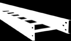
39 Aluminum SWAGEd tubular Cable Ladder Trays Is a structure consisting of two side rails, connected by individual rungs and is manufactured in accordance with NEMA Standard #VE-1. Rungs are fastened to the side members by an exclusive swaging process. This assembly method ensures a superior mechanical and electrical connection. RUNG SPACING (center-to-center) RUNG LOAD DEPTH SIDE RAIL TOP FLANGE (stiffened type shown) SIDE RAIL SIDE RAIL HEIGHT WIDTH LENGTH BOTTOM FLANGE Side Members Side members are designed with top and bottom flanges turned outwards. This simplifies fastening the Cable Ladder Trays to the supports. Cable Ladder Trays with outward facing flanges allow complete access within the cable loading area and eliminate the possibility of cable damage from sharp edges within the cable area. The return on the top flange strengthens the side member and allows cables to be smoothly dropped over the side. Rung Ladder rungs are 1.00 (25mm) diameter tubings flattened on top to provide a cable bearing surface. This construction allows cables to drop out anywhere without contacting a sharp edge. Rung Spacing The interval at which rungs are swaged to the side member. This is measured from center line of rung to center line of rung. SFSP manufactures straight lengths with four standard rung spacings: 6 (150mm), 9 (229mm), 12 (305mm) and 18 (457mm). Rung spacing is generally determined by the size and type of the cable being supported. When in doubt, 9 (229mm) rung spacing is a generally accepted compromise. Length The longitudinal dimensions of standard Cable Ladder Trays are 10 (3.0m), 12 (3.7m), 20 (6.1m) and 24 (7.4m). Width The transverse dimensions of Cable Ladder Trays are measured inside (from side member web to side member web) and are furnished in seven standard widths: 6 (150mm), 9 (229mm), 12 (305mm), 18 (457mm), 24 (610mm), 30 (750mm) and 36 (915mm). Overall Width Overall ladder width is equal to the inside or nominal width plus the width of the side member flanges. 39
, 4 (100mm), 5 (125mm) and 6 (150mm) in accordance with NEMA Standard VE-1. Overall Height Overall height is equal to the loading depth plus 1.25 (30mm).")
40 Aluminum SWAGEd tubular Cable Ladder Trays Load Depth Measured from top surface of rung to the top of the side member. This is not to be confused with the overall height. SFSP manufactures four loading depths: 3 (75mm), 4 (100mm), 5 (125mm) and 6 (150mm) in accordance with NEMA Standard VE-1. Overall Height Overall height is equal to the loading depth plus 1.25 (30mm). Fittings For changing direction horizontally and vertically, SFSP manufactures elbows, tees and crosses in all widths and loading depths. Fittings are available in three standard radii; 12 (305mm), 24 (610mm) and 36 (915mm). Maintain a nominal 9 (229mm) rung spacing through the center line of all fittings. Swaged Rounded Tubular Cable Ladder Trays Features: 1. Universal Curvilinear Splice Plate System The splice plates for rigid connections have a slight curve so that they can be used on straight sections or fittings. Tightening of the fastener pulls the plate flush with the side rail,which makes the fasteners snug and the joint becomes superior structurally and electrically. Even when hand-tight, there is pressure on the fastener to hold it securely. Note: Heavy Duty and Mid Span Splice Plates are available upon request. 2. New Zero Tangent Fittings Tangent as referred to on Cable Tray fittings is the straight part at the end of the curve to accommodate a flat splice plate. This wastes space in tightly packed areas, such as spreader rooms, where the heat of thousands of cables accumulate. Eliminating tangents allows more tray runs to distribute the heat. Zero tangent fittings can save up to 12 (3.7m) per row of tray. 3. Swaged Rung Cable Ladder Trays System Process The heart of the design is the tubular rung and its connection to the side rail by cold swaging, a process where special machinery compresses and locks the tubular rung material around both the inside and outside of the Cable Trays side rails. This connection is made without the use of heat which can potentially disturb the molecular structure of the metal and weaken it. The tubular rung is flattened during the swaging process to ensure a proper cable bearing surface. 40 Technical Information

 section of tray can be lifted on one end with little or no twisting or bending of the tray section.")

41 Swage Advantages Swaging allows the side rails to be turned outwards, simplifying cable installation and providing 100% access to the cables. Cold swaging yields the most rigid tray systems in the industry. The swaged rung connection resists stresses in all directions: up or down, side to side or in and out. The swaged ladder also resists the camber and warping effects encountered in a typical welde system. The increased rigidity means that a 24 (7.4m) section of tray can be lifted on one end with little or no twisting or bending of the tray section. This rigid construction makes the trays safer for field personnel to handle and reduces shipping damage. Electrical Properties Electrically, the 106 tons of pressure in the swaging process virtually eliminates the interstices and a homogenous electrical path results in the following: Resistance of Aluminum Swaged Tray: 31 microhms Resistance of Steel Swaged Tray: 37.3 microhms Resistance of Popular Aluminum Welded Tray: 101 microhms Conclusion Cold swaging yields a very strong, efficient and aesthetically pleasing system that stands the test of time and offers installation savings due to its ease of handling. 41
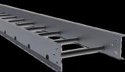
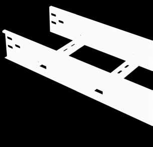
42 Steel Cable Ladder Trays Rounded Tubular Rung Slotted C-Channel Rung Is a prefabricated metal structure consisting of reinforced Welded Cable Ladder Trays -shaped rungs, arc welded to the side rails and is manufactured according to NEMA Standard VE-1. Welded Cable Ladder Trays rungs are fastened to the side rails with an automatic, self-indexing MIG-arc-welding system, plug welding a 0.5 (12.5mm) diameter zone. The superior strength of the plug weld withstands the rigors of shipping, handling, erection and cable support service. Side Members Welded Cable Ladder Trays side members are designed with top and bottom flanges turned inwards. This minimizes the space requirements of the Cable Trays Systems, and allows a very low side rail height for each NEMA Standard VE-1 load depth. Slotted Rungs Slotted shaped rungs are provided on trays 6 (150mm), 9 (229mm), 12 (305mm), 18 (457mm) and 24 (610mm) wide. All slotted rungs are 2.5 (63mm), and provide a 1.25 (30mm) cable bearing surface. Slots provide a neat, convenient option for cable tie down requirements. Slots are 5 16 (6.25mm) wide and 5 8 (12.5mm) in length, and are located on 1 (25mm) centers across the entire width of the rung Solid Rungs Solid shaped Rungs are provided on trays 30 (750mm) and 36 (915mm) wide. Solid Rungs for steel trays are 2.25 (58mm) wide and provide a 7 8 (22mm) cable bearing surface. Rung Spacing SFSP manufactures straight lengths with four standard rung spacings; 6 (150mm), 9 (229mm), 12 (305mm) and 18 (457mm). The 6 (150mm) rung spacing results in a 3.75 (94mm) opening between rungs allowing the tray to be classified as a ventilated trough per NEMA Standard VE-1. Length The longitudinal dimensions of standard Welded Cable Ladder Trays are 10 (3.0m), 12 (3.7m), 20 (6.1m) and 24 (7.4m). Width The transverse dimensions of Welded Cable Ladder Trays are measured from the inside and are furnished in seven standard widths: 6 (150mm), 9 (229mm), 12 (305mm), 18 (457mm), 24 (610mm), 30 (750mm) and 36 (915mm). 42 Technical Information
43 Upside Downside Overall Width Overall tray width is equal to the inside or nominal width plus the thickness of the two side rail webs. Overall Tray Width = Nominal (5mm) Width. Load Depth Measured from the top surface of the rungs to the top of the side member. SFSP manufactures four load depths; (73mm), (101mm), (127mm) and (153mm) corresponding to the four nominal load depths in NEMA Standard 1 (25mm), 3 (75mm), 4 (100mm), 5 (125mm) and 6 (150mm). Overall Height Welded Cable Ladder Trays overall height is equal to the load depth plus 1.25 (30mm). Fittings For changing direction both horizontally and vertically, SFSP manufactures tees and crosses in all widths and load depths. Standard fittings maintain a nominal 9 (229mm) rung spacing through the center line of the fitting. 43
44 Steel Cable Ladder Trays Welded Ladder Cable Tray Features: 1. Compact Economical System Welded Cable Ladder Trays are an extremely compact economical flange in Cable Trays Systems which allow the designer to utilize these Cable Trays in tight locations. The extremely low profile Welded Cable Ladder Trays Rungs (5 8 high) minimize the required side rail height while maintaining NEMA Standard VE-1 nominal load depths. Overall system height is only 5 8 greater than the actual load depth. 2. Universal Curvilinear Splice Plate System The splice plates for rigid connections have a slight curve so they can be used on straight sections or fittings. Tightening of the fastener pulls the plate flush with the side rail. The fasteners are snug and the joint is superior structurally and electrically. Even when hand-tight, there is pressure on the fastener to hold it securely. Note: Heavy Duty and Mid Span Splice Plates are available upon request. 3. Zero Tangent Fittings Tangent as referred to on Cable Tray fittings is the straight part at the end of the curve to accommodate a flat splice plate. This wastes space in tightly packed areas, such as spreader rooms, where the heat of thousands of cables accumulate. Eliminating tangents allows more tray runs to distribute the heat. Inspection of proper installation of splice plates is done visually. If the plate is bowed away from the rail, nuts shall be tightened. 4. Welded Assembly System Welded Cable Ladder Trays rungs on straight sections are assembled to the side rails using an automatic, these welds are 700% larger and stronger than the common resistance (spot) weld in use today. Electrical properties of the assembly are unequalled; are well within the NEMA requirements due to the continuous electrical path. The mechanical strength of this welded assembly withstands the rigors of shipping, handling, erection and service. The size of the weld keeps the vertical axis of the side rail from sloping inwards under load. The weld maintains the 90 angle between the side rail and bottom. This allows full use of the section properties. Spot welds do not permit this. Also, stresses on spot welds (barely 1 8 (3mm) in diameter) are so severe that breakage often occurs during shipping and erection. Welded Cable Ladder Trays fittings are also assembled by MIG-arc welding. 44 Technical Information

45 45
46 46 Technical Information 03
47 CABLE LADDER TRAY OVERVIEW 47


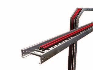
48 CABLE LADDER TRAY SYSTEMS OVERVIEW SFSP s Cable Tray Systems are available in a variety of finishes, and in varying width and load depth for many applications including primary service entrances, main power feeders, branch wirings, instruments and communications cables. Applications: - Industrial: Gas facilities Oil facilities Power Plants Petrochemical Plants Automotive Plants Paper Plants Food Processing Power Plants Refineries Manufacturing Mining - Commercial: Shopping Centers Control Buildings Schools Hospitals Office Buildings Airports Stadiums Features: Rounded side rail flanges protect cables. All designs permit easy cable dropout with no sharp edges to damage insulation. Slotted C-Channel rungs allow simple cable fastening. High strength splices allow random locations between supports (full sections used on all simple beams). Standard straight section length is 3000 mm. Complete line of fittings and accessories. Cable Ladder Trays consist of two longitudinal side rails connected by rungs. SFSP designs are very popular due to their versatility and low costs. They also provide: maximum ventilation for conductor cooling, smooth edges on side rails and rungs to protect cables and slots for easy cable fastening when required. Various rung spacings are available to provide support for most cables, from small flexible cables to the most rigid interlocked armor power cable. 48 Cable Tray Systems Overview
49 SWAGED Cable Ladder Trays (aluminum) Aluminum 6063 T6 - Side Rails Design Data Aluminum 6063 T6 Load Classes Side Rail Height (mm) Load Depth Fd (mm) Thickness (mm) F (mm) W cm 3 I cm 4 Side Rail Load kg/m Span (m) Classes NEMA A A A A A A A C A A A B SFSP s Swaged Cable Ladder Trays consist of 2 outside rails that are connected by a round tubular rung of 25 mm outside diameter. SFSP s Swaged Cable Ladder Trays are manufactured in widths (w): 150 mm, 225 mm, 300 mm, 450 mm, 500 mm, 600 mm, 750 mm and 900 mm. Other dimensions are available upon request. Tubular Rungs The available distance spacing (S) between the rungs is 229 mm. Length (L): 2440/3000 mm. Side height of the side rail is 110 mm, 136 mm, 162 mm and 188 mm. Other dimensions are available upon request. Swaged Cable Ladder Trays are available in: Aluminum 6063 T6 Rail Tubular Rounded Rung x x s L 49

50 SWAGED Cable Ladder Trays (aluminum) (153 mm) (127 mm) (101 mm) (75 mm) C Type Swaged connections make the most rigid tray system in the industry. The swaging process does not affect the temper and strength of surrounding metal the way that traditional welding does. 50 Cable Tray Systems Overview

51 51
52 SWAGED Cable Ladder Trays (aluminum) Aluminum Cable Ladder Trays - General Overview L A C.Ladder Side Rail 6 C.Ladder Side Rail C.Ladder Side Rail 4 C.Ladder Side Rail SFSP can make modifications and design materials or finishes as it deems necessary or desirable. All illustrations, drawings and descriptive material in this publication are of a generally informative nature only, and do not form a complete package of the specifications or description of the goods. Most of the dimensions shown are nominal. 52 Cable Tray Systems Overview
 Plain or slotted, and can be mounted upwards or downwards.")
 MATERIAL THICKNESS 1.50 mm 2.00 mm 2.")
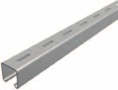
53 Steel Cable Ladder Trays (STEEL S235 JRG2) RUNG TYPES (Swaged and Channel) Swaged Type (Aluminum & Steel) Rounded tubular with 25 mm diameter Rung standard spacing 229 mm Channel Type (Steel) Plain or slotted, and can be mounted upwards or downwards. Rung standard spacing 229 mm RAIL TYPES Types of Rail: C-Type, Z-Type and R-Type MATERIALS Pre-Galvanized / Stainless Steel (See Page 14) FINISHES Hot-Dip Galvanized, Zinc Electroplating and Epoxy Powder Coating. (See Page 14) MATERIAL THICKNESS 1.50 mm 2.00 mm 2.50 mm Rounded Tubular - Swaged or Welded Plain Channel (Steel) Slotted Channel (Steel) Z-Type C-Type R-Type 53
54 Steel Cable Ladder Trays - General Overview Tubular Rounded Rung 25mm diameter X 1.5mm thickness (t) RUNG L W SIDE RAIL S S Rung Types and Dimensions Rung Thicknesses: 1.5 mm, 2.0 mm and 2.5mm 21 Downwards 50 mm 13 X 30 mm 41 Upwards (slots only upon request ) 54 Cable Tray Systems Overview
55 Length and Rung Spacing Side Rail Types Height of rail 50mm - 150mm All Units are in (mm) 55
56 56 Cable Tray Systems Overview 04

57 ladder TYPE RUNS aluminum SECTION 57

58 58 Aluminum Ladders Swaged Tubular Rung Aluminum 6063 T6
59 Aluminum 6063 T6 NEMA Class A (52 kg/m by 3.0m) and 8A (95 kg/m by 2.40m) NEMA Class C (97.0 kg/m by 3.0 m) NEMA Class 12 A (74 kg/m by 3.70 m) NEMA Class 12 B (134 kg/m by 3.70 m) Aluminum 6063 T6 - Side Rails Design Data Load Classes Side Rail Height (mm) Load Depth Fd (mm) Thickness (mm) F (mm) W cm 3 I cm 4 Side Rail Load kg/m Span (m) Classes NEMA A A A A A A A C A A A B F T Side Height Load Depth Tubular Rung 59
60 ALT - A1 (Swaged Rounded Tubular) ALUMINUM LADDER - Tubular Rung Aluminum 6063 T6 NEMA Class A (52 kg/m by 3,0m) and 8A (95 kg/m by 2,40m) Side Rail: A1 Height: 110 mm Load Depth: 82 mm Rung - Spacing: 229 mm 20 Tubular Rounded Rung 9.5 H W L NEMA CLASS A Width Support Distance Load Rung Deflection Rail (mm) (m) KN/m (mm) (mm) Side Rail A1 Side Height: 110 Load Depth: Tubular Rung All Units are in (mm) X 20 X Rung: 25x1.5 mm Width )mm( Order Example Item (h) (w) Type ALT - A C ALT - A C Order Example: ALT - A1 - Side height (h) - Width(w) - Side type For more ordering details, please check page 136 Other dimensions can be manufactured and supplied upon request. 60 Aluminum Ladders
61 ALT - A2 (Swaged Rounded Tubular) ALUMINUM LADDER - Tubular Rung Aluminum 6063 T6 NEMA Class C (97.0 kg/m by 3.0 m) Side Rail: A2 Height: 138 mm Load Depth: 108 mm Rung - Spacing: 229 mm 20 H Tubular Rounded Rung 9.5 W L NEMA CLASS A Width Support Distance Load Rung Deflection Rail (mm) (m) KN/m (mm) (mm) Side Rail A1 Side Height: 138 Load Depth: Tubular Rung All Units are in (mm) Tubular Rung: 25x1.5 mm X 20 X Tubular Rung: 25x2.0 mm Width )mm( Order Example Item (h) (w) Type ALT - A C Tubular Rung: 30x1.5 mm 225 ALT - A C Order Example: ALT - A2 - Side height (h) - Width(w) - Side type For more ordering details, please check page 136 Other dimensions can be manufactured and supplied upon request. 61
 Side Rail: A3 Height: 162 mm Load Depth: 132 mm Rung - Spacing: 229 mm 20 H Tubular Rounded Rung 9.")
62 ALT - A3 (Swaged Rounded Tubular) ALUMINUM LADDER - Tubular Rung Aluminum 6063 T6 NEMA Class 12 A (74 kg/m by 3.70 m) Side Rail: A3 Height: 162 mm Load Depth: 132 mm Rung - Spacing: 229 mm 20 H Tubular Rounded Rung 9.5 W L NEMA CLASS A Width Support Distance Load Rung Deflection Rail (mm) (m) KN/m (mm) (mm) Side Rail A1 Side Height: 162 Load Depth: Tubular Rung Tubular Rung: 25x1.5 mm All Units are in (mm) X 20 X Tubular Rung: 25x2.0 mm Width )mm( Order Example Item (h) (w) Type Tubular Rung: 30x1.5 mm 150 ALT - A C ALT - A C Order Example: ALT - A3 - Side height (h) - Width(w) - Side type For more ordering details, please check page 136 Other dimensions can be manufactured and supplied upon request. 62 Aluminum Ladders
63 ALT - A4 (Swaged Rounded Tubular) ALUMINUM LADDER - Tubular Rung Aluminum 6063 T6 NEMA Class 12 B (134 kg/m by 3.70 m) Side Rail: A4 Height: 138 mm Load Depth: 158 mm Rung - Spacing: 229 mm H Tubular Rounded Rung W L NEMA CLASS A Width Support Distance Load Rung Deflection Rail (mm) (m) KN/m (mm) (mm) Side Rail A1 Side Height: 188 Load Depth: Tubular Rung Tubular Rung: 25x1.5 mm All Units are in (mm) X 20 X Tubular Rung: 25x2.0 mm Tubular Rung: 30x1.5 mm Width )mm( Order Example Item (h) (w) Type ALT - A C Tubular Rung: 30x2.0 mm 225 ALT - A C Order Example: ALT - A4 - Side height (h) - Width(w) - Side type For more ordering details, please check page 136 Other dimensions can be manufactured and supplied upon request. 63
64 64 Introduction 05


65 STEEL ladder TYPE RUNS STEEL SECTION 65

66 66 Steel Ladders Swaged Tubular Rung Steel S235 JRG2
 NEMA Class 16A (82 kg/m by 4.90m) NEMA Class 12A (87 kg/m by 3.70m) NEMA Class 12C (150 kg/m by 3.70m) NEMA Class D (67 kg/m by 6.")
67 Steel S235 JRG2 NEMA Class 8C (149 kg/m by 2.40m) NEMA Class 12A (74 kg/m by 3.70m) NEMA Class 12B (118 kg/m by 3.70m) NEMA Class 12A (74 kg/m by 3.70m) NEMA Class 12B (123 kg/m by 3.70m) NEMA Class 16A (82 kg/m by 4.90m) NEMA Class 12A (87 kg/m by 3.70m) NEMA Class 12C (150 kg/m by 3.70m) NEMA Class D (67 kg/m by 6.0m) Steel S235 JRG2 - Side Rails Design Data Side Rail Classes Height Load Depth Thickness F W I NEMA (mm) Fd (mm) (mm) (mm) cm 3 cm 4 Span Class S A S B S A S A S C S D Load Classes Side Rail Load Span Classes kg/m (m) NEMA S A S B S A S A S C S D F T Side Height Load Depth Tubular Rung 67
68 SLT - S1 STEEL LADDER - Swaged Tubular Rung Steel S235 JRG2 NEMA Class 12A (74 kg/m by 3.70m) Side Rail: S1 Height: 105 mm Load Depth: 75 mm Rung - Spacing: 229 mm H Tubular Rounded Rung NEMA CLASS 12A Width Support Distance Load Rung Deflection Rail (mm) (m) KN/m (mm) (mm) W Side Rail S1 L Side Height: 105 Load Depth: Tubular Rung All Units are in (mm) X 20 X Tubular Rung: 25 X 1.5 mm Width )mm( Order Example Item (h) (w) Type SLT - S C SLT - S C Order Example: SLT - S1 - Side height (h) - Width(w) - Side type For more ordering details, please check page 136 Other dimensions can be manufactured and supplied upon request. 68 Steel Ladders
69 SLT - S2 STEEL LADDER - Swaged Tubular Rung Steel S235 JRG2 NEMA Class 12B (123 kg/m by 3.70m) Side Rail: S2 Height: 130 mm Load Depth: 100 mm Rung - Spacing: 229 mm H Tubular Rounded Rung W L NEMA CLASS 12A Width Support Distance Load Rung Deflection Rail (mm) (m) KN/m (mm) (mm) Side Rail S1 Side Height: 130 Load Depth: Tubular Rung All Units are in (mm) X 20 X Tubular Rung: 25 X 1.5 mm Width )mm( Order Example Item (h) (w) Type SLT - S C SLT - S C Order Example: SLT - S2 - Side height (h) - Width(w) - Side type For more ordering details, please check page 136 Other dimensions can be manufactured and supplied upon request. 69
 (m) KN/m (mm) (mm) Side Rail S1 Side Height: 155 Load Depth: 125 2.0 Tubular Rung 2.40 4.93 0.02 4.19 150 3.0 3.21 0.01 6.")
70 SLT - S3 STEEL LADDER - Swaged Tubular Rung Steel S235 JRG2 NEMA Class 16A (82 kg/m by 4.90m) Side Rail: S3 Height: 155 mm Load Depth: 125 mm Rung - Spacing: 229 mm H Tubular Rounded Rung W L NEMA CLASS 12A Width Support Distance Load Rung Deflection Rail (mm) (m) KN/m (mm) (mm) Side Rail S1 Side Height: 155 Load Depth: Tubular Rung All Units are in (mm) X 20 X Tubular Rung: 25 X 1.5 mm Width )mm( Order Example Item (h) (w) Type SLT - S C SLT - S C Order Example: SLT - S3 - Side height (h) - Width(w) - Side type For more ordering details, please check page 136 Other dimensions can be manufactured and supplied upon request. 70 Steel Ladders
 (m) KN/m (mm) (mm) Side Rail S1 Side Height: 105 Load Depth: 75 2.5 Tubular Rung 2.40 3.34 0.01 6.33 150 3.0 2.14 0.01 9.")

71 SLT - S4 STEEL LADDER - Swaged Tubular Rung Steel S235 JRG2 NEMA Class 12A (87 kg/m by 3.70m) Side Rail: S4 Height: 105 mm Load Depth: 75 mm Rung - Spacing: 229 mm H Tubular Rounded Rung W L NEMA CLASS 12A Width Support Distance Load Rung Deflection Rail (mm) (m) KN/m (mm) (mm) Side Rail S1 Side Height: 105 Load Depth: Tubular Rung All Units are in (mm) X 20 X Tubular Rung: 25 X 1.5 mm Width )mm( Order Example Item (h) (w) Type SLT - S C SLT - S C Order Example: SLT - S4 - Side height (h) - Width(w) - Side type For more ordering details, please check page 136 Other dimensions can be manufactured and supplied upon request. 71
72 SLT - S5 STEEL LADDER - Swaged Tubular Rung Steel S235 JRG2 NEMA Class 12C (150 kg/m by 3.70m) Side Rail: S5 Height: 130 mm Load Depth: 100 mm Rung - Spacing: 229 mm H Tubular Rounded Rung W L NEMA CLASS 12A Width Support Distance Load Rung Deflection Rail (mm) (m) KN/m (mm) (mm) Side Rail S1 Side Height: 130 Load Depth: Tubular Rung All Units are in (mm) X 20 X Tubular Rung: 25 X 1.5 mm Width )mm( Order Example Item (h) (w) Type SLT - S C SLT - S C Order Example: SLT - S5 - Side height (h) - Width(w) - Side type For more ordering details, please check page 136 Other dimensions can be manufactured and supplied upon request. 72 Steel Ladders
73 SLT - S6 STEEL LADDER - Swaged Tubular Rung Steel S235 JRG2 NEMA Class D (67 kg/m by 6.0m) Side Rail: S6 Height: 155 mm Load Depth: 125 mm Rung - Spacing: 229 mm H Tubular Rounded Rung W L NEMA CLASS 12A Width Support Distance Load Rung Deflection Rail (mm) (m) KN/m (mm) (mm) Side Rail S1 Side Height: 155 Load Depth: Tubular Rung All Units are in (mm) X 20 X Tubular Rung: 25 X 1.5 mm Width )mm( Order Example Item (h) (w) Type SLT - S C SLT - S C Tubular Rung: 25 X 2.0 mm Order Example: SLT - S6 - Side height (h) - Width(w) - Side type For more ordering details, please check page 136 Other dimensions can be manufactured and supplied upon request. 73

74 74 Steel Ladders Channel Rung Steel S235 JRG2
 NEMA Class 12B (123 kg/m by 3.70m) NEMA Class 16A (82 kg/m by 4.90m) NEMA Class 12A (87 kg/m by 3.70m) NEMA Class 12C (150 kg/m by 3.70m) NEMA Class D (67 kg/m by 6.")
75 welded C-CHANNEL - LADDER TYPE RUNS Steel S235 JRG2 NEMA Class 8C (149 kg/m by 2.40m) NEMA Class 12A (74 kg/m by 3.70m) NEMA Class 12B (118 kg/m by 3.70m) NEMA Class 12A (74 kg/m by 3.70m) NEMA Class 12B (123 kg/m by 3.70m) NEMA Class 16A (82 kg/m by 4.90m) NEMA Class 12A (87 kg/m by 3.70m) NEMA Class 12C (150 kg/m by 3.70m) NEMA Class D (67 kg/m by 6.0m) Steel S235 JRG2 - Side Rails Design Data Side Rail Classes Height Load Depth Thickness F W I NEMA (mm) Fd (mm) (mm) (mm) cm 3 cm 4 Span Class S A S B S A S A S C S D Load Classes Side Rail Load Span Classes kg/m (m) NEMA S A S B S A S A S C S D F Side Height Load Depth T C.Channel 21x41 mm 75
76 SL - S1 STEEL LADDER - Channel Rung NEMA Class 12A (74 kg/m by 3.70m) Side Rail: S1 Height: 105 mm Load Depth: 75 mm Rung - Spacing: 229 mm Steel S235 JRG2 20 NEMA CLASS 12A Width Support Distance Load Rung Deflection Rail (mm) (m) KN/m (mm) (mm) Side Rail S1 Side Height: 105 Load Depth: C.Channel 21X All Units are in (mm) X 20 X Rung 41 x 21 x 1.5 mm Width )mm( Order Example Item (h) (w) Type SL - S C SL - S C Order Example: SLT - S1 - Side height (h) - Width(w) - Side type For more ordering details, please check page 136 Other dimensions can be manufactured and supplied upon request. 76 Steel Ladders
77 SL - S2 STEEL LADDER - Channel Rung NEMA Class 12B (123 kg/m by 3.70m) Side Rail: S2 Height: 130 mm Load Depth: 100 mm Rung - Spacing: 229 mm Steel S235 JRG2 20 NEMA CLASS 12A Width Support Distance Load Rung Deflection Rail (mm) (m) KN/m (mm) (mm) Side Rail S1 Side Height: 130 Load Depth: C.Channel 21X All Units are in (mm) X 20 X Rung 41 x 21 x 1.5 mm Width )mm( Order Example Item (h) (w) Type SL - S C SL - S C Order Example: SLT - S2 - Side height (h) - Width(w) - Side type For more ordering details, please check page 136 Other dimensions can be manufactured and supplied upon request. 77
78 SL - S3 STEEL LADDER - Channel Rung NEMA Class 16A (82 kg/m by 4.90m) Side Rail: S3 Height: 155 mm Load Depth: 125 mm Rung - Spacing: 229 mm Steel S235 JRG2 20 NEMA CLASS 12A Width Support Distance Load Rung Deflection Rail (mm) (m) KN/m (mm) (mm) Side Rail S1 Side Height: 155 Load Depth: C.Channel 21X All Units are in (mm) Rung 41 x 21 x 1.5 mm X 20 X Rung 41 x 41 x 1.5 mm Width )mm( Order Example Item (h) (w) Type 150 SL - S C Rung 41 x 41 x 1.5 mm 225 SL - S C Rung 41 x mm Order Example: SL - S3 - Side height (h) - Width(w) - Side type For more ordering details, please check page 136 Other dimensions can be manufactured and supplied upon request. 78 Steel Ladders
79 SL - S4 STEEL LADDER - Channel Rung NEMA Class 12A (87 kg/m by 3.70m) Side Rail: S4 Height: 105 mm Load Depth: 75 mm Rung - Spacing: 229 mm Steel S235 JRG2 20 NEMA CLASS 12A Width Support Distance Load Rung Deflection Rail (mm) (m) KN/m (mm) (mm) Side Rail S1 Side Height: 105 Load Depth: C.Channel 21X All Units are in (mm) X 20 X Rung 41 x 21 x 1.5 mm Width )mm( Order Example Item (h) (w) Type SL - S C Rung 41 x 21 x 2.0 mm 225 SL - S C Order Example: SL - S4 - Side height (h) - Width(w) - Side type For more ordering details, please check page Other dimensions can be manufactured and supplied upon request. 79
 Side Rail: S5 Height: 130 mm Load Depth: 100 mm Rung - Spacing: 229 mm Steel S235 JRG2 20 NEMA CLASS 12A Width Support Distance Load Rung Deflection Rail (mm) (m) KN/m (mm) (mm) Side Rail S1")
80 SL - S5 STEEL LADDER - Channel Rung NEMA Class 12C (150 kg/m by 3.70m) Side Rail: S5 Height: 130 mm Load Depth: 100 mm Rung - Spacing: 229 mm Steel S235 JRG2 20 NEMA CLASS 12A Width Support Distance Load Rung Deflection Rail (mm) (m) KN/m (mm) (mm) Side Rail S1 Side Height: 130 Load Depth: C.Channel 21X All Units are in (mm) Rung 41 x 21 x 1.5 mm X 20 X Rung 41 x 21 x 2.0 mm Width )mm( Order Example Item (h) (w) Type 150 SL - S C Rung 41 x 41 x 1.5 mm 225 SL - S C Rung 41 x 21 x 2.0 mm Order Example: SL - S5 - Side height (h) - Width(w) - Side type For more ordering details, please check page 136 Other dimensions can be manufactured and supplied upon request. 80 Steel Ladders
 (m) KN/m (mm) (mm) Side Rail S1 Side Height: 155 Load Depth: 125 2.5 C.Channel 21X41 2.40 6.06 0.03 4.21 150 3.0 3.94 0.02 6.72 3.70 2.59 0.01 1.33 4.90 1.28 0.01 16.29 2.40 6.06 0.09 4.")
81 SL - S6 STEEL LADDER - Channel Rung NEMA Class Steel S9 Side Rail: S6 Height: 155 mm Load Depth: 125 mm Rung - Spacing: 229 mm Steel S235 JRG2 20 NEMA CLASS 12A Width Support Distance Load Rung Deflection Rail (mm) (m) KN/m (mm) (mm) Side Rail S1 Side Height: 155 Load Depth: C.Channel 21X Rung 41 x 21 x 1.5 mm All Units are in (mm). 155 X 20 X Rung 41 x 21 x 2.0 mm Rung 41 x 41 x 1.5 mm Rung 41 x 21 x 2.5 mm Rung 41 x 41 x 1.5 mm Rung 41 x 21 x 2.0 mm Width )mm( Order Example Item (h) (w) Type 150 SL - S C SL - S C Other dimensions can be manufactured and supplied upon request. Order Example: SL - S6 - Side height (h) - Width(w) - Side type For more ordering details, please check page
82 82 Introduction 06


83 LADDER TYPE FITTINGS 83


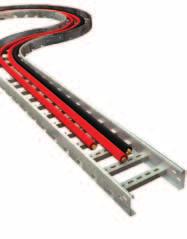
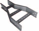
84 84 LADDER FITTINGS LADDER TYPE FITTINGS SFSP fittings are available in bending radii of 300, 450, 600 and 900 mm to accommodate a wide range of cable sizes and types. The horizontal and vertical elbows are available in 450 and 900 of arc. All illustrations shown herein depict our standard ladder rung. The rung spacing of ladder fittings is generally maintained at the fitting centerline. Cable Ladder Tray fittings are usually manufactured in two types: cornered and curved.


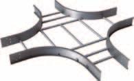


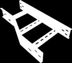
85 Bend T 2110R Bend T 2410R Tee Branch T 2710R Horizontal Cross (Intersection) R 85


")


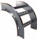

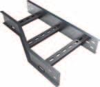

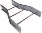
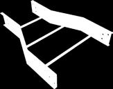
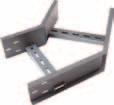
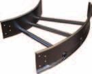
86 86 LADDER FITTINGS Inside Vertical Elbow (Inside Riser) T 3310R Outside Vertical Elbow (Outside Riser) T 3610R Straight Central Reducers R Right Hand Reducers R


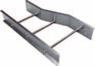
87 Left Hand Reducers R 87
88 88 LADDER FITTINGS 07

89 LADDER Tray ACCESSORIES 89
90 CONNECTORS Straight connector / R Order Example Item (h) (t) h R Order Example: Side height (h) - Thickness (t) For more ordering details, please check page 136 Angle connector / R h h R Order Example: Side height (h) - Thickness (t) For more ordering details, please check page 136 Adjustable Vertical Connector 1030 / 1030 R Order Example 100 T 100 T Item (h) (t) H H R Adjustable Horizontal Connector 1040 / 1040 R Order Example: Side height (h) - Thickness (t) For more ordering details, please check page 136 Order Example Item (h) (t) h H R R Order Example: 1040/1040R - Side height (h) - Thickness (t) For more ordering details, please check page Ladder Type Accessories
91 Barrier Strip 1070 For Cable Trays For Cable Ladders 1070 Available Lengths: 2440 / 3000 mm Available Lengths: 2440 / 3000 mm Drop-out plate / 1110 For Cable Trays For Cable Ladders 1110 Cable Tie / 1120 For Cable Trays For Cable Ladders Nylon ties provide easy attachment of Ladder Cable Tray rungs
92 CONNECTORS rimping Type Copper C Tubular Cable Terminal Ends / 1200 G H B C D E Cable mm2 Stud A Hole B C Bonding Jumper / 1300 Dimensions (mm) A D C D G A BH 6 C6 9 D Threaded Rod Size mm B J Nut Hanger Washer Ladder Type Accessories Dimensions (mm) J E E Current Rating AMP Cover Trunking Lid Trunking Body 2 Self Tapping Screw Screw, Nut and Washer J Earth Wire Green / Yellow
93 Functions Ladder Cable Tray covers shall be considered for any of the following purposes: Protection from falling objects or debris, as may occur beneath personnel walkways. Shielding from ultraviolet rays of the sun and guarding against other weathering elements. Minimizing accumulation of foreign contaminants such as ash or other industrial deposits. Protection of cables and personnel where a riser tray penetrates a floor or grating. COVERS Solid Cover 2000 Ventilated Cover Covers Side Height Types : Solid without flange - (SOF) Solid with flange - (SWF) Ventilated without flange - (VOF) Ventilated with flange - (VWF) 2100 Order Width SFSP Example )mm( Item Type (W) )t( 2000 SWF Cable covers are supplied with or without a 15 mm down turned flange. Straight section covers are furnished 3000 mm long. All fitting covers are furnished in solid design only. Order Example: Type - Width (w) - Thickness (t) For more ordering details, please check page 136 Ladder Cable Tray Covers with Locking Clamp Covers Side Height Types : Solid without flange - (VOF) Solid with flange - (VWF) Width )mm( Order Example Item (W) )t( Order Example: Type - Width (w) - Thickness (t) For more ordering details, please check page
94 94 Ladder Type Accessories 08


95 FASTENERS, bolts AND NUTS 95
96 FRAMING SYSTEMS Round Washers DIN 125, ASTM F436 Washers (SRW) DIN 125 ASTM F436 Zinc Plated Stainless Steel D d S (mm) (mm) (mm) M6 M M8 M M10 M M12 M M16 M M18 M M20 M Order Example: SRW - M 12 -DIN 115 Round Washers DIN 440, DIN 9021 Washers (SRW) DIN 440, DIN 9021 DIN Zinc Plated Stainless Steel D d S (mm) (mm) (mm) 440 M M8 M M10 M M M12 M M16 M Order Example: SRW - M 12 DIN 9021 Square Washers SSW Square Washers (SSW) SSW 40/40 for all channels 41/21 Series SSW 41/41 for all channels 41/41 Series H.D. Glavanized Bolt Stainless Steel Bolt a x b x d (mm) M8 M10 40 x 40 x (4-5-6) M10 M12 40 x 40 x (4-5-6) M12 M16 40 x 40 x (4-5-6) Order Example: SSW 41/41 M 12 - d 96 Fixing Accessories System

 Electroplated Thread Stainless Steel Thread D L Load cap. (mm) (mm) (kn) M6 M6 10/10 15 2.")
97 Fully Threaded Rods Grade 4.6 DIN 975 ASTM A 36, A193 Threaded Rod (STR) - DIN ASTM A36 Zinc Plated Thread Length Load cap. (mm) (kn) M6 2000/ M8 2000/ M / M / M / M M Round Head Machine Screws Round Head (SRH) DIN 7985 Zinc Plated Thread Length (mm) d (mm) M M M Order Example: SRH - M 10 DIN 7985 Coupler Sleeves Rounded Coupler Sleeves (SCS) Electroplated Thread Stainless Steel Thread D L Load cap. (mm) (mm) (kn) M6 M6 10/ M8 M8 12/ M10 M10 13/ M12 M12 16/ M16 M16 21/ M20 M20 26/ Order Example: SCS - M
98 FRAMING SYSTEMS Roofing Bolts Roofing Bolts (SRB) - Materials : low carbon steel, carbon steel - Steel S235, grade 4.6, 4.8 and Surfaces : plain, black and zinc plated - Length = X (mm) Y (mm) M4 x - y M5 x - y M6 x - y M8 x - y Thread Size (mm) (mm) (mm) (mm) Length Order Example: SRB - M 6 Carriage Bolts with Nut Below Head DIN 603 Carriage Bolts )STC( H P E Zinc Plated H.D. Glavanized Grade 4.6 Head (E) (E) (A) mm Head (H) mm Square Width (O) mm Square Depth (P) mm M5 M M6 M Order Example: STC - M 6 O M8 M M10 M M16 M A Hexagon Nuts DIN 934, DIN EN 24032, ASTM A 563 Hexagon nut (SHN) DIN 934 or ISO 4032 (= DIN EN 24032) ASTM A563 m e S Zinc Plated Thread Stainless Steel Thread S/m DIN S/m ISO (mm) (mm) (mm) M6 M6 10/5 10/ M8 M8 13/6.5 13/ M10 M10 17/8 16/ M12 M12 19/10 18/ M16 M16 24/13 24/ M18 M18 26/16 26/ M20 M20 30/18 29/ e Order Example: SHN - M Fixing Accessories System
99 Hexagonal Rod Coupler Grade 8.8 ASRM a 563 Hexagonal Rod Coupler with view hole (SHR) Electroplated Thread Stainless Steel Thread D L Load cap. (mm) (mm) (kn) M10 M M12 M M16 M M 18 M M 20 M Order Example: HRC - GV - M 12 Machine HexHead Bolts DIN 933, DIN 24017, ASTM A307, A449 Hex Head Bolt (SHB) DIN 933 or EN ASTM A307, A449 (without nut) Zinc Plated Dimension Stainless Steel Dimension M 6 x 12 M 6 x 25 M 8 x 25 M 8 x 25 M 8 x 40 M 10 x 20 S DIN S EN (mm) (mm) Order Example: HB - 7P - M 12 x 1000 M 10 x 30 M 10 x 30 M 10 x 45 M 10 x 45 M 10 x 60 M 10 x 70 M 12 x S M 12 x 25 M 12 x 25 M 12 x 30 M 12 x 30 M 12 x 40 M 12 x 40 M 12 x 50 M 12 x 60 M 12 x 60 M 12 x 80 M 12 x 80 M 12 x 90 M 16 x 40 M 16 x M 16 x 60 M 16 x 60 M 16 x 90 M 16 x 90 M 18 x 40 M 18 x M 18 x 50 M 18 x 50 M 18 x 60 M 18 x 60 M 18 x 80 M 18 x 80 M 20 x 40 M 20 x Hex Head Bolt USED in combination with channels nuts. M 20 x 50 M 20 x 50 M 20 x 60 M 20 x 60 M 20 x 80 M 20 x
100 100 Fixing Accessories System 09


101 Cantilevers & Beams 101
102 Channel SFSP s metal framing channel is cold formed on modern rolling machines from low carbon steel manufactured according to BS 6946:1988. A continuous slot provides the ability to make attachments at any point. Lengths Standard length: 3000mm with ± 3.2mm length tolerance. Custom lengths are available upon request. Finishes Standard Finishes: Pre-Galvanized finish (ASTM A653M coating G90 and G60). Hot Dip Galvanized after fabrication (ASTM A123 or BSEN ISO1461:2009). Other custom coatings are available upon request. GENERAL INFORMATION 102 Support Systems

103 Metal Framing Channels Selection Chart 22.0 Part No Channel Dimensions Height H Width W Thickness CCH - 220/ mm 41.0 mm 1.5 mm CCH - 240/ mm 41.0 mm 1.5 mm CCH - 320/ mm 41.0 mm 2.0 mm CCH - 340/ mm 41.0 mm 2.0 mm CCH - 420/ mm 41.0 mm 2.5 mm CCH - 440/ mm 41.0 mm 2.5 mm For Toothed Channel add T after the Part no. ex: CCH-220T CCH Material Thickness for 1.5 mm 2 for 2.0 mm 3 for 2.5 mm 4 Size mm 21/41-2 mm 41/41-4 T Channel Patterns PT - 0 ST - 1 B2B - 2 Toothed channel Channel Hole Patterns PT Plain Type ST Slotted Type B2B Type Toothed channel type Part No Thick. mm. Height H Part No Thick. mm. Height H Part No Thick. mm. Height H CCH CCH CCH CCH CCH CCH CCH CCH CCH CCH CCH CCH CCH CCH CCH CCH CCH CCH For Toothed Channel add T after the Part no. ex: CCH-220T 103
104 Cantilever Arm Bracket Cantilever Arm Brackets - SCA CCH421 41x21x2.5 A Length Allowable Load A (mm) F 1 * F 2 * F z ** Base plate : height (h) x width (b) x thickness (t) In the case of concrete support frame, use anchor M10 In the case of concrete C-Channel frame, Hexbolt M8. ** Connection force (pull-out force) : 3.10 (kn) A Length Allowable Load A (mm) F 1 * F 2 * F z ** Base plate : height (h) x width (b) x thickness (t) In the case of concrete support frame, use anchor M16. In the case of concrete C-Channel frame, Hexbolt M8. ** Connection force (pull-out force) : 7.50 (kn) * Given Loads are always in [kn] Allowable characteristic live load 25 F 1 or F 2 h 25 h-50 1/2 A 1/2 A Length A (mm) b t 104 Support Systems
 x width (b) x thickness (t) 140 50 10 In the case of concrete support frame, use anchor M12.")
105 Cantilever Arm Brackets - SCA CCH422 41x21x2.5 B2B A Length Allowable Load A (mm) F 1 * F 2 * F z ** Base plate : height (h) x width (b) x thickness (t) In the case of concrete support frame, use anchor M12. In the case of concrete C-Channel frame, Hexbolt M8. ** Connection force (pull-out force) : 4,8 (kn) CCH442 41x41x2.5 B2B A Length Allowable Load A (mm) F 1 * F 2 * F z ** Base plate : height (h) x width (b) x thickness (t) In the case of concrete support frame, use anchor M16. In the case of concrete C-Channel frame, Hexbolt M10. ** Connection force (pull-out force) : 8,30 (kn) * Given Loads are always in [kn] Allowable characteristic live load F 1 or F 2 25 h b 25 h-50 t 1/2 A 1/2 A Length A (mm) 105
106 Cantilever Arm Bracket U - Support / All Units are in (mm). U-Support with welded-on head plate 200 x 100 x 5mm Order Example Item (h) (t) Order Example: Length (L) - Thickness (t) For more ordering details, please check page 136 I - Support / 3050 Head Plate / x 100 x 5mm All Units are in (mm). U-Support with welded-on head plate 200 x 100 x 5mm Order Example Item (h) (t) Order Example: Length (L) - Thickness (t) For more ordering details, please check page Support Systems
107 Wall Bracket / For U-Support Thickness 5 mm for I-Support U-Support with welded-on head plate 200 x 100 x 5mm Order Example Item (h) (t) Order Example: Length (L) - Thickness (t) For more ordering details, please check page 136 Support Connectors / 3300 Clamping Plates / Order Example Item (h) (t) Order Example: 3300/ Length (L) - Thickness (t) For more ordering details, please check page

108 Cantilever Arm Bracket Support Plates / Angles / Welded Head Plate Head Plate Head Plate: variable, transverse Carrier lug Support Bracket Head Plate: variable, longitudinal Support connector 108 Support Systems
109 Hold Down Clamp Support Clamps / 3450 Clamping Angles /
110 110 Support Systems 10


111 heavy duty Anchoring SYSTEMS 111
112 General Information Direction of Loading The direction of the applied load shall be considered to determine the most appropriate anchor. The tension and shear components shall be lesser than the recommended load/design resistance in the direction concerned. Tensile Loading Tensile loads are applied along the axis of fixing (see Fig.1). Common examples include suspended ceiling applications and the suspension of mechanical services, pipework, ductwork,etc... Shear Loads Shear loads act at right angles to the axis of fixing and directly against the face of the structural material (see Fig.2). Shear performance is governed mainly by the shear strength of the bolt material and by the compressive strength of the supporting substrate. Oblique / Combined Loads Oblique loads are a combination of tension and shear components (see Fig.3). If the angle of the applied oblique load is within 10 of pure tension or pure shear, the safe working load for that direction may be assumed. Otherwise, the applied oblique load shall be resolved into its shear and tensile components. Offset Loads Offset loads act at right angles to the fixing axis but are offset from the surface (see Fig.4). In this situation, the deflection of the bolt due to bending needs to be considered as well as the shear capacity of the anchor Slotted Holes in Fixture When fixing anchors through slotted holes; it is important to ensure that there is an adequate surface of contact between the washer and the fixture to guarantee a positive clamping force. If in doubt, a square plate washer with a thickness of 3mm or above would be recommended in place of the standard washer supplied. Diamond Drilled Holes When holes are formed in the structure using a diamond drilling system; extra care is required to ensure the holes are thoroughly cleaned by brushing and blowing for at least three times. Also, to make a key for the anchor (particularly if a bonded anchor is installed) the sides of the hole shall be roughened up by inserting a standard masonry bit into the hole attached to a hammer action drilling machine. A resin with minimal shrinkage shall be selected for diamond drilled holes. 112 Heavy Duty Anchors
113 Fig.1 Fig.2 Fig.3 Fig
114 Expansion Steel Anchor - STM STM Expansion Steel Anchor STM/H Features: Suitable for all screws or threaded bolts with metric thread. Low energy impact, power-saving assembly. Multiple removing and fixing. Inside threaded anchor, allows great flexibility. Can use variable lengths and art of threaded rods or bolts. Small edge distance and small distance between anchors. Provide uniform load by tightening the screw or hexagon nut, the cone pulls into the expansion anchor and tightens against the drilled hole. Suitable for use in concrete and natural stone. Typical Applications: Cable Management, handrails, brackets, staircases, ladders, machines, window panels, base plates, scaffoldings and frameworks Technical Data: Recommended loads (non cracked -concrete C 20/25). Type (order No) Tension Load Shear Load Bending Moment (kn) (kn) (Nm) Screw Grade M M M M *for cracked concrete we shall use 0,5 x this value (approximately) Materials: zinc plated steel. stainless steel [ SS 304 (A2), SS 316 (A4) ]. 114 Heavy Duty Anchors
115 Setting Data: Edge distance > 1,5 x H eff., distance between anchors > 3 x H eff. Thickness of foundation > 2 x H eff. Size H eff. Edge Distance C Installation Parameters: Distance Between Anchors S Thickness of Foundation hmin Washer Tightening Torque Spanner size (mm) (mm) (mm) (mm) (Ø) (Nm) (mm) M x M x M x M x H eff = Effective anchorage depth. Bolt Size Throughbolt, stainless steel A4/316 Length exp.unit Drill (Ø) Drilling depth H eff. Usable Length Screw Ø x Length (mm) (mm) (mm) (mm) (mm) (mm) M M6 x 50 M M8 x 60 M M10 x 80 M M12 x 90 Usable Length Thickness of Foundation Features European Technical Appro Torque controlled expansi Applications in damp area Stainless steel A4/316 Face xing or through xin Applications facades, cable trays, railings, s under-constructions, high-ra Spaner Size M Bolt Size Tension load Shear load Bending moment Heff. Edge Distance Distance between (kn) (kn) (Nm) (mm) C (mm) anchor S (mm) Washer M H eff M Drilling depth M M Length M Washer (Ø) 12 x x x x x 3.0 Installation Installation T inst Drill a hole and clean it with a brush, remove dust with a blower. 2 - Place the plug and the object to fix. 3 - Tighten the screw. 4 - Fixing completed. Plug & drill Ø Length (mm) (mm) Usable Length (mm) 5 10
116 Drop-in Anchor - SDA SDA Features: Provides permanently fixed threaded socket in concrete. Use in non-cracked concrete or cracked concrete and natural stone. The anchor will spread and tighten against the drilled hole after inserting with setting tool. Low setting depth, reduced drilling time. Enables cost-effective assembly. Multiple removing and fixing. Typical Applications: Pipes, ventilation ducts, suspended ceilings, sprinkler systems, brackets, threaded rods and Cable Trays. Technical Data: Type (order No) Tension Load Shear Load Bending Moment Screw Grade (kn) (kn) (Nm) M M M M *for cracked concrete we shall use 0,5 x this value (approximately) Materials: zinc plated steel. stainless steel [ SS 304 (A2), SS 316 (A4) ]. Setting Data: Edge distance > 1.5 x effective anchorage depth, distance between anchors > 3,0 x effective anchorage depth, min. thickness of foundation > 2,5 x H eff. Size H eff. Edge Distance C Distance Between Anchors S Thickness of Foundation hmin Washer Tightening Torque Spanner size (mm) (mm) (mm) (mm) (Ø) (Nm) (mm) M M M M M Heavy Duty Anchors
117 :34:42 E ANCHOR - STAINLESS STEEL Install with manual setting tool or mechanical (T setting tool 2. Easy Face to install xing by or hammer through action. xin 1. Internally threaded to take stud or bolt. inst ) for use with hammer action drilling machines. 3. Slotted sleeve and captive interna 25 g tool 2. Easy to install 11 by hammer 8 action WA-06 facilitate MAXIMUM ANCHOR HOLE HOLE easy setting and expans 30 THREAD THREAD LENGTH Applications RECOMMENDED 3. Slotted sleeve 13 and captive 10 LENGTH internal tapered 32 wedge 11to DIAMETER DEPTH WA-08 PRODUCT SIZE TYPICAL APPLICATIONS (mm) facades, TORQUE 40 (mm) (mm) (mm) cable trays, railings, CODE s facilitate easy 15 (d) setting and 12 expansion. 42 (l e For ( l ) G ) WA-10 (Nm) permanently fixing threaded sockets (d o ) in concrete (h and o ) good under-constructions, quality stone WA-12 (T inst ) high-ra e Ideal for secure fixing for mechanical services, cable trays, platforms, drain covers, suspended 65Installation 25 Parameters: M e Securing equipment 67 that may 95 need to be removed or replaced. WA-16 rete and good 80 quality stone. 35 M WA , cable trays, H eff = Effective anchorage depth. R-DCA platforms, WEDGE drain ANCHOR M10covers, - ZINC suspended 40PLATEDceilings 15 etc Anchor Length H eff oved or replaced. M TEEL Effective MAXIMUM Anchor Thread Drill Drilling Min. ANCHOR Screw Max.Screw HOLE HOLE Thread M16 65 Anchorage THREAD 25 THREAD 20 LENGTH RECOMMENDED D ng Tool HOLE DIAMETER (mm) (d o ) ( l ) (d o ) (h o ) Length Length (Ø) Depth Depth LENGTH E Depth E DIAMETER DEPTH Size Bolt Size Tension load Shear Depth load SIZEH eff. Bending moment (mm) Heff. Edge Distance Distance between TORQUE (mm) (d) MAXIMUM (mm) (mm) ANCHOR (mm) (mm) (kn) HOLE (mm) (mm) (kn) HOLE (mm) (mm) (Nm) (l Drill Ø ( l ) G (mm) (mm) ) C (mm) anchor S (mm) (Nm) THREAD LENGTH ETA PENDING RECOMMENDED 2007 (d o ) (h o ) (T inst ) LENGTH DIAMETER DEPTH PRODUCT M6 M25 6 (mm) TORQUE NEW CODE (mm) (mm) (mm) Mechanical Setting CODE Tool 120 M8 M30 8 (l ( l ) G ) MAXIMUM (Nm) HOLE (d E E= Screw Depth M10 M o ) (h o ) RECOMMENDED (T inst 17 ) DEPTH M PRODUCT Drilling Depth M TORQUE NEW CODE 18 (mm) M CODE WA-A M16 (h (Nm) o ) (T inst ) WA-A Installation WA WA-A4-10 THREAD SIZE 10 50Installation (d) WA WA-A4-12 R-DCA 1 WEDGE ANCHOR 2- STAINLESS STEEL M WA WA-A M WA-12 ANCHOR HOLE HOLE THREAD THREAD LENGTH LENGTH DIAMETER DEPTH SIZE (mm) M10 Mechanical Setting Tool WA-16 (mm) (mm) (mm) T (d) (l inst ( l ) G ) (d o ) (h o ) M WA-20 2 M Tighten to the recommended torque. 4 - Fixing completed. M20 MAXIMUM RECOMMENDED TORQUE (Nm) (T inst ) PRODU Washer CODE (Ø) M x x 1.6 M x 2.0 M x x 3.0 M M M THREAD (d) M6 M Drill a hole and clean it with a brush, M6 remove dust with 25 a blower Insert the anchor sleeve 27in the hole M16 M M20 M M READ Usable Plug & drill Ø Length nhole SIZE MAXIMUM THREAD SIZE GRIP TYPE HOLE M Length (d) Manual Setting RECOMMENDED Tool (d) DIAMETER DEPTH PRODUCT (mm) (mm) (mm) TORQUE NEW CODE M6 (mm) (mm) CODE M6 SDS-plus Use Manual the setting Setting tool Tool to drive (Nm) (d o ) (h o ) the internal wedge into the anchor (T inst ) Mechanical Setting Tool M8 M8 SDS-plus M WA-A4-06 M10 SDS-plus M WA-A4-08 M12 SDS-plus M WA-A4-10 M16 SDS-max M WA-A4-12 M20 SDS-max WA-A quired 2. Remove debris and 3. Insert wedge anchor, 4. Use the setting 10 tool to Altern 15 Mechanical Setting Tool epth. thoroughly clean hole with slotted end drive the internal 10 wedge 110 settin 30 chanical Alternatively Setting brush Tool use and the pump. mechanical setting tool with an appropriate drilling machine. into the anchor drillin sory Service Tel: +44 (0) , Fax: +44 (0) Installation b and 3. Insert wedge anchor, 4. Use the setting tool to 5. Alternatively 16 use mechanical an hole with slotted end drive the internal wedge setting tool with 16 appropriate p. into the anchor. drilling machine M8 PRODU M10 CODE 1. Drill a hole of required diameter and depth , Fax: +44 (0) Remove debris and thoroughly clean hole with brush and pump. 3. Insert wedge anchor, slotted end first. 4. Use the setting tool to drive the internal wedge into the anchor. 5. A s d 34 Technical Advisory Service Tel: +44 (0) , Fax: +44 (0)
118 Sleeve Anchor - SAS Features: Suitable for use in concrete, natural stone, brickwork and blockwork Small distance between anchors. Optimum performance in most base material types. No protruding threads after installation. Small distance between anchors and from edge. Controlled expansion. Zinc plated > 5µm. Effective force distribution in the drilled hole. Sleeve anchor with hexagon screw or with threaded bolt. SAS Typical Applications: Uni-channel,railings, steel constructions, machines, high-racks, cable support systems and mechanical fixations. Technical Data: Recommended loads (non cracked-concreted C 20/25). Bolt Size Tension Load Shear Load Torque Moment (kn) (kn) (Nm) M M M M *for cracked concrete we shall use 0,5 x this value (approximately) Materials: zinc plated steel. stainless steel [ SS 304 (A2), SS 316 (A4) ]. Setting Data: Edge distance > 1.5 x effective anchorage depth, distance between anchors > 3,0 x effective anchorage depth, min. thickness of foundation > 2,5 x H eff. Bolt Size H eff. Edge Distance C Distance Between Anchors S Thickness of Foundation hmin Washer (Ø) Tightening Torque Spanner size (mm) (mm) (mm) (mm) (mm) (Nm) M x M x M x M x Sleeve Anchor - SAS: with hexagon screw (non-cracked concrete C20/25). Hole Ø in Fixture Drilling Depth Setting Depth Min.Usable Length Size Length Drill H eff. (mm) (Ø) (mm) (mm) (Ø) (mm) (mm) M Spaner Size M Usable Length Drill Ø Drilling Depth M M M M Washer H eff Setting Depth M Length *for cracked concrete we shall use 0,5 x this value (approximately). 118 Heavy Duty Anchors
119 load d (kn) (kn) (Nm) (mm) C (mm) M M 1(Nm) 0 (Nm) M12 M anchor S (mm) (Ø) x 1.6 thickness thickness 4.1 Tighten Min. Min. 16 x 1.6 M 8 moment 7 5 Spanner Bending moment Distance between Distance to edge torque Spanner Spanner Spanner Distance between Distance to edge Shear Tighten torque Shear loadload Bending (kn) (kn) anchor 26.5 anchor S (mm) S (mm) (Nm)(Nm) Installation of Sleeve Anchor - SAS I nsta lla tion 1 2 C (mm) C (mm) of found 8 7 size (SAS) size (SAS) size (SAB) size (SAB) 58 of found 20 x 2.0 (hmin) mm mm (hmin) 24 x x Tinst Tinst Tinst 1 - Drill a hole and clean it with a brush, remove dust with a blower. 2 - Insert the sleeve anchor through the fixture Drill ØDrm lesnagbtlh eg tttih ngsdeetp with hexagon screw 2hexagon illm Ø mm LengthLength ThreadThDrreilalidngDdreilp litnhgu desapb thleu elesn titnhgdepth enchor Anchor with screw into the hole. 3 - Tighten to the recommended torque. mm mm Sleeve Anchor - SAB: With threaded bolt and nut. Size M6 Length Drill (Ø) Hole Ø in Fixture Min. Drilling Depth Min. Setting Depth H eff. (mm) (mm) (mm) (mm) (Ø) (mm) with threaded nut M6threaded 64 bolt 8and 10 enchor Anchor with bolt and nut M M M M M M M M M M M Installation ( push-through installation ) 1 Length Length (mm) (mm) mm mm mm mm min. min. mm mm M6 M6 Usable MPlug 6 M 6& drill Ø Length Length M 8 M(mm) 8 (mm) (mm) M8 M M 1 0M M 1 0M 1 06 Max Usable Length (mm) Usable Length Drilling Usable Setting 5 Se Drilling Usable Plug & drill Ø Length Spanner 25 Plug & drillmø Length Length Depth M Drill ØDepth Depth Length Size (mm) 5 Dep (mm) (mm) (mm) (mm) (mm) (mm) 1 0 (mm) 40 (mm) 60 5 ( Washer H0 eff Setting Depth Drilling Depth Length Drilling Usable Setting Drilling Usable Setting Size Drill Ø Length Usable depthsetting Usable depth m Se depth min.drill a hole. 2 - Remove dust Sizea blower Drilland Ø cleanlength 1Drilling - Place thelength fixture (object) and with the hole depth withdrilling a brush. length depth length depth min. depth length dep (mm) (mm) (mm) (mm) (mm) (mm) (mm) (mm) (mm) 3 - Tap the anchor(mm) through the fixture tool. 4 -(mm) Tighten to the(mm) recommended torque. (mm) (mm) (mm) with a hammer or a setting(mm) (mm) ( installation ) Installation ( pre-positioned M6 M6 M6 M8 M6 M8 M8 M10M8 3 M10M10 M Drill a hole of requested diameter and depth. 2 - Remove dust with a blower and clean the hole with a brush. 3 - Tap with a hammer or a setting tool until fixing depth is reached. 4 -Tighten to the recommended torque
120 Through Bolt (Wedge Anchor) - STB Features: Suitable for use in cracked concrete or in non-cracked concrete and in natural stone. Special design of the clip in stainless steel which ensures a safe hold in the hole. Torque controlled expansion. Zinc plated > 5µm. User friendly, face fixing or through fixing. SDB Typical Applications: Uni - channel, hand rails, steel constructions, Cable Trays, supports, brackets, ducts and shelf feet. Technical Data: Through bolt zinc plated (non-cracked C20/25). Usable Length Drilling Depth Tension Load Shear Load Torque Moment Bolt Size (kn) (kn) (Nm) M Throughbolt, stainless steel Drill Ø A4/316 M M M M Materials: *for cracked concrete we shall use 0,5 x this value (approximately) Zinc plated steel. Stainless steel [ SS 304 (A2), SS 316 (A4) ]. Metal Products 120 Heavy Duty Anchors M HA Washer H eff Setting Depth Bolt Length F Features Europe Torque Applic Stainle Face x A Applicati fa facades, c u under-co Feature Smal Torqu Zinc Throu Setting Data: Bolt Bolt Size Size Tension Tension load load Shear load Shear load Bending Bending moment moment Heff. Heff. Edge Distance Edge Distan (kn) (kn) (kn) (kn) (Nm) (Nm) (mm) (mm) C (mm) Applica C (mm) anch M6 M steel 60 con Edge distance > 1,5 H eff., distance between M8anchors > x H 4.1 eff M Thickness of foundation > 2 x H eff. M10 87 M12M Edge Distance M16M Thickness 14 of Tightening 120 Bolt H eff. Distance Between Washer Foundation Torque Spanner Size C Anchors S hmin Size (mm) (mm) (mm) (Ø) (mm) (Nm) M Installation x M Installation 16 x M x M x M Type 240 Tension 30 load x 3.0 Shear 160 load 80 Bending moment 24 Tighten torque Distance between Distance T inst (Order No) (kn) (kn) (Nm) (Nm) anchor S (mm) C (m M6 M8 M10 M Throughbolt, stainless steel A4/316 Sleeve Anchor Through bolt
121 Installation Parameters: roughbolt, stainless steel steel A4/316 A4/316 Tension load load (kn) (kn) Through bolt zinc plated, stainless steel or hot-dip galvanized. Hole Ø in Usable Length Bolt Length Drill Ø Drilling Depth Setting Depth H eff. Bolt Size Fixture Fix (mm) (mm) (mm) (mm) (mm) (mm) (mm) M M Applications Applications facades, facades, cable cable trays, trays, railings, railings, steel steel constructions, constructions, machines, under-constructions, high-racks, high-racks, 50 pro pro les 20 les M M Shear Shear load load Bending Bending moment moment Heff. Heff. Edge Edge Distance Distance Distance Distance between between Washer Washer Thickness Thickness of of Tighten Tighten torque tor foundation 65 (kn) (kn) (Nm) (Nm) (mm) (mm) C (mm) C (mm) anchor anchor S (mm) S (mm) (Ø) foundation (Ø) (Nm) (mm) (mm) (Nm) x x M x x x x x x x x H eff.= Effective anchorage depth Installation ( pre-positioned installation ) Installation Features Features European European Technical Technical Approval Approval Option Option 7 for 7 uncracked for uncracke co Torque Torque controlled controlled expansion expansion Applications Applications in damp in damp areas areas and and outdoors outdoors Stainless Stainless steel steel A4/316 A4/316 Face Face xing xing or through or through xing xing T inst T inst T inst 1 - Drill a hole and clean with a brush, remove dust with a blower. Place the fixture and insert the through bolt with a hammer. 3 - Tighten to the recommended torque. Plug Plug & drill & drill Ø ØLength Length (mm) (mm) (mm) (mm) Usable Usable Setting Setting Length Length depth depth min. min. (mm) (mm) (mm) (mm)
122 Shield Anchor - SSA Features: Assembly detachable, multiple removing and fixing. Low energy impact, power-saving assembly. Force controlled expansion. Flexibility inside threaded anchor. Variable length and art of threaded rods or bolts. By tightening the screw, the cone pulls into the sleeve and tense against the drill hole. Small edge distance and small distance between anchor. Expansion elements are held together by a spring. Optimum taper nut angle for maximum expansion. Pressed steel segment ensures consistent dimensional accuracy. Provide a projecting stud to support fixture during installation and removal. Suitable for use in concrete, natural stone, brick and sand stone. SSA Typical Applications: For fixing: steel constructions, handrails, consoles, brackets, ladders, gates and spacing designs. Technical Data: (Recommended loads concrete C 20/25 and in brick work). Size Materials: Distance to Edge C Zinc plated and die-cast. Setting Data: Distance Between Anchors S Min. Thickness of Foundation hmin H eff. (mm) (mm) (mm) (mm) M M M M Edge distance > 1,5 x H eff., distance between anchors > 3 x H eff. Thickness of foundation > 2 x H eff. Concrete Brick Work Torque Size Tension Shear Tension Shear Concrete Torque Brick KN KN KN N.m N.m M M M M *for cracked concrete we shall use 0,5 x this value (approximately) 122 Heavy Duty Anchors
123 Installation Installation Parameters: A- Using a hexagon screw: insert shield only, place the fixture over the hole and insert a hexagon screw with a washer through the fixture. B- Using a threaded bolt and nut: insert the shield with a threaded bolt, position the fixture over the thread and add a washer with a nut. A- Shield Anchor with Hexagon Screw: Size M6 M8 M10 M12 Installation Bolt Length Min.Drill Ø Shield Length Min. Hole Depth Setting Depth H eff. Usable Length Spanner Size (mm) (mm) (mm) (mm) (mm) (mm) T inst 1 - Drill a hole and clean it with a brush, remove dust with a blower. 2 - Place the plug and the object to fix. 3 - Tighten the screw. 4 - Fixing completed. B- Shield Anchor with Threaded Bolt and Nut: Size M6 M8 M10 M12 Throughbolt, stainless steel A4/316 Features European Technical Approval Option 7 for uncracked concrete Torque controlled expansion Threaded Min. Hole Min. Drill Ø Shield Length Applications Setting in Depth damp areas Usable and outdoors Length Spaner Size Length Depth Stainless steel H eff. A4/316 (mm) (mm) (mm) (mm) Face xing or through xing (mm) (mm) Applications facades, cable trays, railings, steel constructions, 60 machines, Bending moment 60 Heff. Edge 65Distance 50 under-constructions, high-racks, pro les Distance between Washer Thickness 30 of foundation anchor S (mm) (Ø) 60(mm) x x x x x Bolt Size Tension load Shear load Tighten torque Spanner (kn) (kn) (Nm) (mm) C (mm) (Nm) size M M M M M Installation T inst Drill a hole and clean it with a brush, remove dust with a blower. 2 - Place the plug and the object to fix. 3 - Tighten the screw. 4 - Fixing completed. Plug & drill Ø (mm) Length (mm) Usable Length (mm) Setting depth min. (mm)
124 Resin Capsule, Epoxy-Acrylate - (cea) Features: European Technical Approval Option 8 for uncracked concrete Small edge and space distances Temperature range short term: -40 C C Temperature range long term: -40 C C Anchor rod with 45 end Typical Applications: Steel constructions, Cable Trays, guard rails, under-constructions and machines Materials: Stainless Hot-Dip Galvanized. Technical Data: Recommended loads (concrete C 20/25). Tension load Shear load Bending moment Bending moment A4-70 Distance betw. anchors (s) Edge distance (c) Min. distance betw. anchors (smin) Min. edge distance (cmin) Min. thickness of found. (hmin) Tighten torque Spanner size (kn) (kn) (Nm) (Nm) (mm) (mm) (mm) (mm) (mm) (Nm) M M M M M M20/ M20/ M M CEAL M CEAL M CEAL M CEAL M CEAL M CEAL M Safety factor 2.5 / 1 kn 100 kg Temperatures: Temperature -5 to 5 C (min.) 5 to 20 C (min.) 20 to 30 C (min.) 30 C and more (min.) Hardening times Heavy Duty Anchors
125 Resin Capsule, Epoxy-Acrylate (CEA) Ø Length Drilling Hole Ø Drilling Depth (mm) (mm) (mm) (mm) Resin Capsule, Epoxy-Acrylate (CEA) (setting depth 1.5x) Ø Length Drilling Hole Ø Drilling Depth (mm) (mm) (mm) (mm) Fit to Anchor Rod M8x M10x M12x M16x M20x M24x405 Setting Tool for rods without drive For M8, M10, M12, M14, M16, M20, M24, M
126 Resin Capsule, Epoxy-Acrylate - (cea) Anchor Rod Thread Thread Thread Length (mm) Usable Length (mm) M M M M M M M M M M M M Throughbolt, stainless Throughbolt, steel stainless A4/316 steel A4/316 M M M M M Anchor Sleeve with internal thread Ø Drilling Hole Ø Drilling Depth Min. Screw in (mm) (mm) (mm) (mm) M M M M16 Bolt Size 20Tension load 28 Shear Bolt load Size 125 Tension Bending load moment 24 Shear Heff. load Bending Edge moment Distance Distance Heff. between Edge Distance Washer Distance Thickness between of foundation (kn) (kn) (kn) (Nm) (kn) (mm) (Nm) C (mm) anchor (mm) S (mm) C (mm) (Ø) anchor S (mm) M (mm) M M x M M x M M x M M x M16 14 M x Materials: Zinc Plated Steel Hot-Dip Galvanized. Installation 1 2 Installation 3 Features Features European Technical Approval European Option Technical 7 for uncracked Approval con Op Torque controlled expansion Torque controlled expansion Applications in damp areas Applications and outdoors in damp areas and Stainless steel A4/316 Stainless steel A4/316 Face xing or through Face xing xing or through xing Applications Applications facades, cable trays, railings, facades, steel cable constructions, trays, railings, machines, steel co under-constructions, high-racks, under-constructions, pro les high-racks, p 5 Tighten Washer torque Thi fo (Ø)(Nm) 12 x x x x x T inst T inst 1-2Drill a hole of requested 2diameter and depth. 2 - Remove dust with a blower and clean the hole with a brush. 3 - Tap with a hammer or a setting tool until fixing depth is reached. 5 - Tighten to the recommended torque. 126 Heavy Duty Anchors Plug & drill Ø (mm) Length (mm) Usable Plug & drill Ø Setting Length Length depth min. (mm) (mm) (mm) (mm) Usable Length (mm) S de

127 127
128 128 Heavy Duty Anchors 11


129 FIRESTOP SYSTEMS 129


130 SFSP SFSP PRODUCT DESCRIPTION BASIC USE COMPOSITION & MATERIALS PRODUCT SELECTOR FIRESTOP SEALANTS COMPOSITE SHEET FIRESTOP MORTAR FIRESTOP PUTTY FIRESTOP PILLOWS PATHWAYS PUTTY PADS FIRE PROTECTIVE CABLE COATING Specialized Construction Technologies Firestop Systems

131 BETA CONTECH Beta Contech is specialized in advanced architectural and industrial products, ranging from raised access to flooring systems, architectural expansion joint systems, architectural impact protection systems, firestopping systems and others. The company operates within the GCC and MENA countries and has a wide reputation among contractors. STI FIRESTOP Specified Technologies is an industry leader solely committed to the development of innovative, reliable firestopping solutions that help stop the spread of fire smoke and toxic fumes. Beta Contech s innovative firestop solutions are for all types of new construction and retrofit applications. PRODUCT DESCRIPTION Basic Usage These products are used solely or in combination to construct firestop systems effective in sealing through-penetrations, construction joints and high traffic openings against the spread of fire, smoke or hot gasses. A wide range of tested systems is available for standard constructions and penetrants with ratings up to 4 hours. These products and systems are suitable for sealing electrical, plumbing, mechanical or data/communications penetrations, including: Pipes, Conduits or Ducts Metallic Nonmetallic Insulated Cables Telephone Power Data and Control Cable Trays and Bus Ducts Steel Aluminum and Copper Construction Joints Composition & Materials STI Firestop products are a unique combination of passive and intumescent (expands when heated) materials. Products utilizing this expansion mechanism exhibit unusually fast and aggressive, highly directionalized expansion


132 PRODUCT DESCRIPTION Firestop Sealants Triple S Intumescent Sealant Premium grade, water-based firestop caulk featuring STI s patented two-stage intumescent technology. The perfect choice for the broadest array of combustible and non-combustible electrical penetrants requiring a permanent, durable seal. Firestop Sealants LCI Intumescent Sealant Standard grade, water-based firestop caulk engineered to address most common combustible and noncombustible electrical applications typically found in light commercial construction. Pathways EZ-Path Fire Rated Pathway A mechanical cable pathway system utilizing a self-contained, self-sealing firestop system. Easy moves, adds and changes with no firestopping required ever. Three sizes and a full range of accessories adapt this system to virtually any application. Putty Pads SSP Putty Pads When used with both metallic and non-metallic switch and receptacle boxes, pads are UL Tested and Classified to permit larger boxes and reduced spacing. 132 Firestop Systems


133 Composite Sheet Intumescent Composite Sheet Lightweight, easily fabricated panel surface mounts to walls and floors to provide a neat, clean seal for medium to large openings typically used for Cable Trays, bus ducts, and conduit banks. Fire Protective Cable Coating CS Cable Spray Water-based spray applied coating used to provide short term circuit integrity and improved flame spread characteristics for grouped electrical cables. Firestop Mortar SSM Firestop Mortar A strong, lightweight and cementitious mortar designed for large openings typically used for Cable Trays or banks of conduits. Firestop Putty SSP Intumescent Putty Non-hardening intumescent putty which is easily installed and removed making it the perfect choice for cable penetrations requiring occasional retrofitting. Firestop Pillows SSB Intumescent Firestop Pillows Compressible cushions are easily installed and removed. The perfect firestop solution for medium to large openings including cable bundles, Cable Trays, bus ducts and multiple conduits
134 134 Firestop Systems 12


135 HOW TO ORDER 135


136 Ordering Cable ladder Trays & Accessories Materials and finishes abbreviations: Cable trays and accessories are available in the following: Materials & Finishes Aluminium Pre-Galvanized Stainless Steel Code AL PG SS Hot-dip Galvanized Electrolytic Galvanized Powder Coated HD EG PC
137 - Item & Order Number for Sections & Fittings When ordering cable ladder trays, the full order number shall include the material used, width of the tray, side height,type of side and the length rail. SFSP Order Example SFSP 4CL / R 3000 AI PC Item Side Width Thickness Side Length Pre. Galvanized Powder Coated Number Height (mm) (mm) Type (mm) (Materials) (Finishes) Examples: 1- Order number for Aluminum (6063-H34) cable ladder tray, 3050 mm length, 76.2 mm side height, 2.5 mm rail thickness, 1.5 mm rung thickness and 500 mm width with R-type return flange: MCL76A R 3050 Al (6063-H34) 2- Order number for Pre-Galvanized 3000 mm length cable tray, 75 mm side height, 2.0 mm rail thickness, 2.0 mm rung thickness and 300 mm width with Z-type return flange: HCL Z 3000 PG PC 3- Order number for powder coated curved T-branch, 100 mm side height, and 700 mm width with straight end: C PG PC N.B.: Order number for connectors will include the item number, side height and thickness of the sheet. For more information on ordering and types, UCM technical staff are ready to assist you with all necessary details.
138 13


139 LOCATIONS
140 OUTLETS Sales Operations Jeddah / KSA Tel : Fax: unitech.ksa@ikkgroup.com Jeddah - Ghurab Showroom / KSA Tel : Fax: unitech.ksa@ikkgroup.com Mak kah, Taif / KSA Tel : Fax: unitech.ksa@ikkgroup.com Riyadh North / KSA Tel : Fax: unitech.ksa@ikkgroup.com Riyadh South / KSA Tel : Fax: unitech.ksa@ikkgroup.com Riyadh - West / KSA Tel : Fax: unitech.ksa@ikkgroup.com Qassim / Buraidah / KSA Tel : Fax: unitech.ksa@ikkgroup.com Qassim Showroom / KSA Tel : Fax: unitech.ksa@ikkgroup.com Hafr el Batin / KSA Tel : Fax: unitech.ksa@ikkgroup.com Hail / KSA Tel : Fax: unitech.ksa@ikkgroup.com Skakah / Qurayyat / KSA Tel : Fax: unitech.ksa@ikkgroup.com Tabuk / KSA Tel : Fax: unitech.ksa@ikkgroup.com Khamis Mushayt / KSA Tel : Fax: unitech.ksa@ikkgroup.com Najran / KSA Tel : Fax : unitech.ksa@ikkgroup.com Sharorah / KSA Tel : Fax: unitech.ksa@ikkgroup.com Al -Baha / KSA Tel : Fax: unitech.ksa@ikkgroup.com Gizan / KSA Tel : Fax: unitech.ksa@ikkgroup.com Al Qunfudah / KSA Tel : Fax: unitech.ksa@ikkgroup.com Mad inah / KSA Tel : Fax: unitech.ksa@ikkgroup.com Mad inah Showroom - UPF / KSA Tel : Fax: unitech.ksa@ikkgroup.com Yanbu / KSA Tel : Fax: unitech.ksa@ikkgroup.com Design, Logistics, Materials, Media & R&D GERMANY Stuttgart Tel : Fax: unitech.germany@ikkgroup.com CHINA Yiwu - Zhejiang Province Tel : Fax: unitech.china@ikkgroup.com KSA TOSL Jeddah Tel : Fax: tosl.ksa@ikkgroup.com 106
141 Dammam / KSA Tel : Fax: unitech.ksa@ikkgroup.com Dammam / Showroom / KSA Tel : Fax: unitech.ksa@ikkgroup.com Jubail / KSA Tel : Fax: unitech.ksa@ikkgroup.com Hufuf / KSA Tel : Fax: unitech.ksa@ikkgroup.com Hufuf / Showroom / KSA Tel : Fax: unitech.ksa@ikkgroup.com Manama / Bahrain Tel : Fax: unitech.bahrain@ikkgroup.com Kuwait City / Kuwait Tel : Fax: unitech.kuwait@ikkgroup.com Dubai - Al Rashidiyah / UAE Tel : Fax : unitech.dubai@ikkgroup.com Abu Dhabi - Musaffah / UAE Tel: Fax: unitech.auh@ikkgroup.com Al Ain / UAE Tel : Fax: unitech.alain@ikkgroup.com Beirut / Lebanon Tel : Fax: unitech.lebanon@ikkgroup.com Tripoli Showroom / Lebanon Tel : Fax: unitech.lebanon@ikkgroup.com Amman / Jordan Tel : Fax: unitech.jordan@ikkgroup.com Muscat / Oman Tel : Fax : unitech.oman@ikkgroup.com Cairo - El Gomhoria St. / Egypt Tel: Fax: unitech.egypt@ikkgroup.com Tripoli / Libya Tel: Fax: unitech.libya@ikkgroup.com UAE TOSL Jebel Ali Tel : 4304/ Tel : Fax: tosl.jxb@ikkgroup.com LEBANON Tel : Fax:
142 Managing Office Main Branch Branch Factory Design Office Purchasing & Supply
143 l Kingdom of Saudi Arabia, United Arab Emirates, Bahrain, Jordan, Egypt, Lebanon, Germany, China, Oman, Libya, Kuwait.

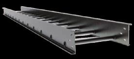

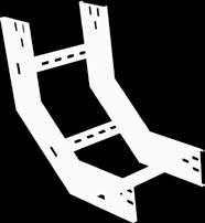
144
CABLE LADDER TRAYS CATALOGUE
 CABLE LADDER TRAYS CATALOGUE INDEX - About SFSP 2 - Cable Ladder Trays 10 - Cable Ladder Trays Run 44 - Ladder Tray Fittings 86 - Ladder Tray Accessories 90 - Cable Tray Support System 97 - Concrete Support
CABLE LADDER TRAY CATALOGUE.
 CABLE LADDER TRAY CATALOGUE www.ikkgroup.com INDEX Cable Ladder Tray Catalogue - About SFSP - Cable Ladder Trays - Cable Ladder Tray Runs - Cable Ladder Tray Fittings - Cable Tray Accessories - Cable Tray
CABLE LAddEr TrAY CATALoguE 1
 CABLE ladder TRAY catalogue www.ikkgroup.com 1 INDEX Cable Ladder Tray Catalogue - About SFSP - Cable Ladder Trays - Cable Ladder Tray Runs - Cable Ladder Tray Fittings - Cable Tray Accessories - Cable
Cable ladder systems. Development and testing
 Cable ladder systems Metsec cable ladder systems have been developed to provide cost effective solutions for the support of cables in a wide range of market sectors. These sectors include: * Coercial *
Series 2, 3, 4 Steel Cable Ladder Steel Cable Ladder, Series 2, 3, 4 & 5
 Cable Ladder with Slotted Rung (shown with alternating slot orientation) Cable Ladder with Slotted Rung (shown with continuous slot down - also available with continuous slot up) HDS-1 Steel Cable Ladder,
ABN Quality Endorsed Company ISO9001 Lic No EDITION 2
 ABN 43 8 71 335 SECTION 4 Cable Ladder and A U S T R A L I A W I D E A U S T R A L I A N M A D E Quality Endorsed Company ISO91 Lic No 13146 EDITION 2 SECTION 4: Cable Ladder & Type 3/5 Type 4/7L Type
CABLE MANAGEMENT SOLUTIONS CATALOGUE2003/04 A COMPLETE CABLE MANAGEMENT SOLUTION FOR COMMERCIAL AND INDUSTRIAL APPLICATIONS.
 CLE MNGEMENT SOLUTIONS CTLOGUE2003/04 COMPLETE CLE MNGEMENT SOLUTION FOR COMMERCIL ND INDUSTRIL PPLICTIONS www.legrand.co.uk FSTRCK F31 FSTRCK F31 SYSTEM STEEL WIRE CLE TRY Legrand With a large range of
Series 1 Steel - Straight Sections
 Series 1 Steel - Straight Sections Series 1 Steel H-1 B-Line series Cable Tray Systems Series 1 Steel - ccessories & Fittings Series 1 Steel How The Service dvisor Works We know that your time is important!
Cable Support Systems Admiralty Pattern Tray Cable Ladder Type 2/30 Cable Ladder Type 3/50 K-1000 Channel KT3/KT5 Ladder Tray
 www.hesales.com.au Cable Support Systems Admiralty Pattern Tray Cable Ladder Type 2/3 Cable Ladder Type 3/5 K- Channel KT3/KT5 Ladder Tray -.55mm base Galvabond - 2.4m length. 14mm side - Self-splicing
CONFIGURATION OF CABLE SUPPORT SYSTEMs
 CONFIGURATION OF CABLE s CABLE TRUNKING Page 4 - page 7 CABLE TRAY Page 8 - page 11 CABLE LADDER Page 12 - page 14 3 SS249/ IEC 61084 COMPLIED STEEL SURFACE CABLE TRUNKING CEE PRODUCT CODE SS-CEE 6 3 (#)
Series 2, 3, 4, & 5 Aluminum - Straight Sections
 - Straight Sections I-1 B-Line series Cable Tray Systems - Accessories For Aluminum Fittings see fittings section pages L-1 thru L-17 How The Service Advisor Works We know that your time is important!
Cable Tray CT2D-18. Tray2Day SM. cable tray service program
 Cable Tray CT2D-18 Tray2Day SM cable tray service program * * At, we believe that power is a fundamental part of just about everything people do. That s why we re dedicated to helping our customers s find
ADDER SYSTEM CABLE L
 17 Introduction CALE LADDE The ICMS cable ladder system consists of a wide range of aluminum and Steel cable ladders, Fittings and accessories. Ladder Trays are available in two models: Tubular rungs mechanically
EZTray. Cable Management Made Easy
 EZTray Cable Management Made Easy PRESENTATION Introduction:.................................. 3 EZ Tray: The Tray That Saves You Time!.............. 4-5 EZ Tray: The Innovative Cable Management Solution....
PRODUCT CATALOGUE - CABLE TRAYS
 PRODUCT CATALOGUE - CABLE TRAYS 098711969 shivshaktiindustries.delhi@gmail.com S. S. Engineering, B-2621, DSIDC Complex, Narela Industrial Area, New Narela, Delhi-140 Table of Contents Perforated Cable
Swifts SW strength, speed and flexibility
 Swifts SW strength, speed and flexibility STEEL WIRE CABLE TRAY / PRODUCT GUIDE Global vision... 21st Century solutions Established in the UK since 1972, Legrand is a world leading manufacturer of products
Wire ø in. Cat. No. ETQ 2002SS *ETQ 2004SS *ETQ 2006SS
 Steel Basket Tray Deep U-Profile Fast connection system, low profile for confined spaces The deep U-profile is ideally suited for light- to medium-duty commercial and industrial applications where space
Welded cable ladder system
 Welded cable ladder system System information Pure OBO cable ladder competence Electricians have placed their trust in OBO Bettermann cable ladders for decades. The range stretches from riveted connections,
Series 2, 3, 4, & 5 Steel - Accessories
 - ccessories Splice Plates Standard 8-hole pattern for all steel splice plates. One pair including hardware provided with straight section. Boxed in pairs Expansion Splice Plates Expansion plates allow
Swifts SW. strength, speed and flexibility STEEL WIRE CABLE TRAY / PRODUCT GUIDE
 Swifts S strength, speed and flexibility STEEL IRE CABLE TRAY / PRODUCT GUIDE Global vision... 2st Century solutions Established in the UK since 972, Legrand is a world leading manufacturer of products
ABN Quality Endorsed Company ISO9001 Lic No EDITION 2
 ABN 43 008 701 335 SECTION 5 Structural Cable Ladder Systems A U S T R A L I A W I D E A U S T R A L I A N M A D E Quality Endorsed Company ISO9001 Lic No 13146 EDITION 2 SECTION 5: Structural Cable Ladder
Bridge Overhang Brackets
 Bridge C49, C49D, C49S and C49JR Bridge Dayton Superior offers the bridge contractor four different Horizontal Length versions of the C49 Bridge Bracket, which allows for maximum adjustability to meet
Product Catalogue. Cable Management Solutions
 Product Catalogue Cable Management Solutions Cable management solutions Introduction Cable ladder & accessories Perforated tray & accessories Trunking & accessories Channel tray & accessories Superstrut
Busway Construction. Bus Bars
 Busway Construction Bus Bars A better understanding of what busway is can be gained by examining its construction. A typical Siemens Sentron busway section has three or four formed aluminum or copper bars
SECTION PIPE HANGERS AND SUPPORTS
 Part I - GENERAL 1.01 SECTION INCLUDES A. The work covered under this section consists of the furnishing of all necessary labor, supervision, materials, equipment, and services to completely execute the
Series 2, 3, 4, & 5 Aluminum - Accessories
 Wedge Lock Splice Plates Standard 4-hole pattern. Furnished in pairs, with hardware. One pair including hardware provided with each section. Boxed in pairs with hardware. For field installation drill 13
2. Runway & Crane System
 2. Runway & Crane System The crane runway girders, crane, columns and building frames can all be regarded as components of the overall crane installation. The individual components cannot be designed in
ONTRAC WIRE MESH CABLE TRAY SYSTEM
 P R O D U C T D ATA S H E E T ONTRAC WIRE MESH CABLE TRAY SYSTEM K E Y F E AT U R E S Available in two styles: Shaped and Standard Tray Easy to use pathway solution that supports large quantities of network
Series 2, 3, 4, & 5 Aluminum - Accessories
 The following is a list of accessories and fittings that can be provided with S8 tray. For more information on these items, contact our Engineering Department. Fittings Horizontal Bends 30 Bends with 24,
PRODUCT CATALOGUE MECHANICALSUPPORT.CO.NZ 0508 CABLE TRAY CERTIFIED QUALITY SYSTEM ISO 9001:2015 REGISTERED COMPANY
 BS OHSAS 18001:2007 & AS/NZS 4801:2001 Certificate No. NZP1023HS R PRODUCT CATALOGUE REGISTERED COMPANY MECHANICALSUPPORT.CO.NZ 0508 CABLE TRAY Who we are Founded in 2005 by Directors Hayden Froggatt and
WORK STATION BRIDGE CRANES
 FREE STANDING WORK STATION BRIDGE CRANES CAPACITIES: SPANS: ENCLOSED TRACKS: PRODUCTIVITY: Up to 4000 lbs Up to 30' Steel, Aluminum & Stainless Steel Average 28% Increase A Class Above... In Productivity.
Channel Cable Tray - Accessories & Fittings
 hannel able Tray - Straight Sections E-1 -Line series able Tray Systems hannel able Tray - ccessories & Fittings How The Service dvisor Works We know that your time is important! That s why the color-coding
STRAIGHT PERFORATED TRAY
 STRAIGHT PERFORATED TRAY RETURNED EDGE TYPE RETURNED FLANGE TYPE NOTE: Other sizes are available upon request WIDTH (W) HEIGHT (H) 50 15 15 150 15 15 15 400 15 500 15 600 15 STRAIGHT CABLE TRAY STANDARD
ORDERING: Specify size, figure number, description, nominal pipe size or special O.D. and C-to-C dimension. C - C LOAD lb.
 Fig. 2110 www.pipingtech.com/fig2110 Sway Strut with 4 of Adjustment Engineered spring supports option 1 option 2 ORDERING: Specify size, figure number, description, nominal pipe size or special O.D. and
Insulating cable tray
 Cable conduction and protection system 66 raw material colour U23X Gris UV 66 U23X For support, protection and conduction of cables Good performance outdoors and to corrosion due to over 40 years experience
INDEX EASY RAIL: THE SOLUTION IS EASY...D4 EXAMPLES OF LOAD CAPACITIES...D5 ORDER CODES...D6 MOUNTING EXAMPLES...D7 TECHNICAL DATA...
 INDEX EASY RAIL: THE SOLUTION IS EASY...D4 EXAMPLES OF LOAD CAPACITIES...D5 ORDER CODES...D6 MOUNTING EXAMPLES...D7 TECHNICAL DATA...D8 STANDARD CONFIGURATIONS...D10 VERIFICATION UNDER STATIC LOAD...D12
# INDEX. Created on: Revised on: N/A Cable Trays Manual 1 ABBREVIATIONS 2 SYSTEM COMPONENTS 3 DEFNITIONS 4 MATERIAL & FINISH OPTIONS
 # INDEX 1 ABBREVIATIONS 2 SYSTEM COMPONENTS 3 DEFNITIONS 4 MATERIAL & FINISH OPTIONS 5 GENERAL INFORMATION 6 ADAPTATION TO NEMA STANDARDS 7 CABLE TRAYS 8 CABLE LADDERS 9 ACCESSORIES 10 SUPPORTS 11 INSTALLATION
WIRE BASKET TRAY CANADIAN ELECTRICAL RACEWAYS INC.
 CANADIAN ELECTRICAL RACEWAYS INC. WIRE BASKET TRAY Made of heavy-gauge zinc plated wire mesh, CER basket tray is ideal for your commercial or industrial cable management project. A full range of cable
CERTIFIED QUALITY SYSTEM ISO 9001:2015 REGISTERED COMPANY
 BS OHSAS 18001:2007 & AS/NZS 4801:2001 Certificate No. NZP1023HS R CABLE TRAY ALUMINIUM CABLE LADDER CABLE TRUNKING PRODUCT CATALOGUE Electrical Cable Containment REGISTERED COMPANY Mechanical Support
Series 3 & 4 Stainless Steel - Accessories
 - Accessories Splice Plates Standard 8-hole pattern for all steel splice plates. One pair including hardware provided with straight section. (Expansion splice quantity subtracted) Boxed in pairs with hardware.
accqpulse Velocity Profiler Sensor Installation Guide
 accqpulse Velocity Profiler Sensor Installation Guide Instruction Sheet #69-7403-012 Released May 2016 Overview This instruction guide is for the installation of the accqpulse shallow water and deep water
Hi-Tech specially designed components allow for fast and easy assembly.
 OPEN SHELVING MEDIUM, HEAVY AND EXTRA HEAVY-DUTY HI-TECH STEEL SHELVING Open Starter Units Include: Two beaded front posts, two angle back posts, one pair of back sway braces, two pair of side sway braces
Industrial Control Transformers
 6 Industrial Control Transformers Section 6 Industrial Control Transformers provide a low and safe control voltage for the operation of electromagnetic devices, such as motor starters, contactors, solenoids
Dearborn Overhead Crane
 A Class Above... In Productivity. In Safety. In Ease of Positioning and Movement. In Ease of Installation. In Designs, Capacities, and Spans. It s no wonder more and more businesses like yours are choosing
User's Manual: Series 270I Model 270I Process Current Loop-Powered Isolator
 User's Manual: Series 270I Model 270I Process Current Loop-Powered Isolator Table of Contents Page Introduction... 1 Description... 1 Specifications... 2 Installation... 3 Calibration... 4 General Maintenance...
Knürr Smaract. Knürr Smaract. CompactRack
 CompactRack Features Ample space for components and cabling provided in an efficient, compact design. The innovative frame concept with triangular extrusions ensures low weight while maintaining high stability.
Supreme. Supreme Framing System. Product Catalog IAPMO UNIFORM ER #0313
 Supreme Supreme Framing System Product Catalog IAPMO UNIFORM ER #0313 2507 Table of Contents Certification of Materials 5 LEED Credits 5 Independent Product Certification 5 Code Approvals, Performance
Power-Limiting Cables
 Power-Limiting Cables This section provides general design guidelines for power-limiting heat-tracing systems installed on insulated metal pipes. For other applications or design assistance, contact your
SECTION LOW VOLTAGE DISTRIBUTION EQUIPMENT
 SECTION 16400 LOW VOLTAGE DISTRIBUTION EQUIPMENT A. General 1. The University does not accept Series-Rated equipment for power distribution switchboards, distribution panels and branch circuit panelboards.
NEMA CABLE LADDER [GENERAL INFORMATION]
![NEMA CABLE LADDER [GENERAL INFORMATION]](/thumbs/93/112454241.jpg "NEMA CABLE LADDER [GENERAL INFORMATION]") NEMA CABLE LADDER [GENERAL INFORMATION] Cable Support Systems NEMA Cable Ladder Cable Tray Acrofil ire Basket Brackets & Supports Unistrut manufactures and markets the largest range of cable ladder systems
NEMA CABLE LADDER [GENERAL INFORMATION] Cable Support Systems NEMA Cable Ladder Cable Tray Acrofil ire Basket Brackets & Supports Unistrut manufactures and markets the largest range of cable ladder systems
EMC Compatible enclosure assembly
 EMC Compatible enclosure assembly 1 The definition of electromagnetic compatibility (EMC) is the ability of an electrical device to function satisfactorily in its electromagnetic environment without adversely
Midwest Dry Type Transformers
 Midwest Electric Products Midwest Dry Type Transformers Reliable and Efficient Performance From a Name You Know DOE 2016 Efficiency Transformers Catalog General Information...2 General Purpose... 3 Single-Phase
Clipper Defined. Shelving. Clipper Hi-Performance Shelving Systems. Growth with. Penco Hi-Performance Shelves. Growth with
 Defined Clipper Hi-Performance Systems At the heart of the Clipper System is the ingenious Penco Clipper Clip. It is easily installed, holds the shelf firmly in place, can be repositioned at any time,
ELITE SERIES R-410A Ready - Multi-Position
 PRODUCT SPECIFICATIONS AIR HANDLERS CBXM ELITE SERIES R-0A Ready - Multi-Position Bulletin No. 0 October 07 Supersedes June 0 Nominal Capacity -. to Tons Optional Electric Heat -. to 0 kw MODEL NUMBER
BUSWAY Low Voltage (Pow-R-Flex)
") BUSWAY LOW VOLTAGE (POW-R-FLEX) PART 1 GENERAL 1.01 1.02 SCOPE The Contractor shall furnish and install the busway system including all necessary fittings, hangers and accessories as specified herein and
BUSWAY LOW VOLTAGE (POW-R-FLEX) PART 1 GENERAL 1.01 1.02 SCOPE The Contractor shall furnish and install the busway system including all necessary fittings, hangers and accessories as specified herein and
MR - MEDIUM RATING A
 88 MR - MEDIUM RATING 160-1000A SECTION CONTENTS 90 General features 96 Advantages 100 Illustrated contents MR MEDIUM RATING 102 Trunking components 110 Feed units and end covers 113 Tap-off boxes 118
CABLE MANAGEMENT SOLUTIONS CATALOGUE2003/04 A COMPLETE CABLE MANAGEMENT SOLUTION FOR COMMERCIAL AND INDUSTRIAL APPLICATIONS.
 CABLE MANAGEMENT SOLUTIONS CATALOGUE03/04 A COMPLETE CABLE MANAGEMENT SOLUTION FOR COMMERCIAL AND INDUSTRIAL APPLICATIONS www.legrand.co.uk CHANNEL SUPPORT THE BACKBONE OF ALL YOUR SUPPORT NEEDS Swifts
Selection Guide Motor Control Device Solutions
 Selection Guide Motor Control Device Solutions Expect more and get it from c3controls. Our portfolio of Motor Control Devices consists of worldclass products designed and manufactured to meet your requirements
T&B Cable Tray. In this section...
 In this section... T& Cable Tray T& Cable Tray Overview... -260-261 luminum Tray... -262-309 Steel Tray... -310-333 One-Piece Tray... -334-357 Channel Tray... -358-373 Common ccessories... -374-376 Grounding
2507 (IBC 2006 ONLY) 3054 (IBC 2006 ONLY) Supreme Framing System Product Catalog
 3054 (IBC 2006 ONLY) Supreme Framing System Product Catalog") 12 0 2 / 2009IANT C B I PL COM 2507 (IBC 2006 ONLY) 3054 (IBC 2006 ONLY) R Supreme Framing System Product Catalog Supreme Framing System The Benefits of Supreme Framing System Speak for Themselves What
12 0 2 / 2009IANT C B I PL COM 2507 (IBC 2006 ONLY) 3054 (IBC 2006 ONLY) R Supreme Framing System Product Catalog Supreme Framing System The Benefits of Supreme Framing System Speak for Themselves What
Design Standard. Purpose: Design Standard:
 Design Standard Purpose: This design standard has the purpose of creating a consistent application of motor-control centers throughout the East Side Union High School District, therefore achieving a standard
BAC, BAF, BAH Central Station Air Handlers
 PRODUCT DATA & INSTALLATION Bulletin B80-BA-PDI-5 Part # 1097717 PRODUCT SUPPORT web: b-rp.ca/bah email: ahu@b-rp.ca call: 1-844-893-3222 x527 scan: BAC, BAF, BAH Central Station Air Handlers Indoor and
Battery Technology for Data Centers and Network Rooms: Site Planning
 Battery Technology for Data Centers and Network Rooms: Site Planning White Paper # 33 Executive Summary The site requirements and costs for protecting information technology and network environments are
Mipco Connections for Refrigerated Containers. No One Does It Like Mipco. The Mipco. Advantage. Reliability. Safety. Easy Installation & Service
 No One Does It Like Mipco Mipco Interlocked Reefer Power Outlets are used extensively in port terminals and shipboard applications to provide a safe, watertight electrical connection for refrigerated containers.
Understanding Electrical Terms
 Understanding Electrical Terms Complimentary brochure from Understanding Electrical Terms In today s computer-intensive work environments, a critical issue is clean, reliable power. Powerlite is the industry
R310EN 2211 ( ) The Drive & Control Company
 The Drive & Control Company") eline Ball Rail Systems R310EN 2211 (2006.04) The Drive & Control Company Bosch Rexroth AG Linear Motion and Assembly Technologies Ball Rail Systems Roller Rail Systems Linear Bushings and Shafts Ball
eline Ball Rail Systems R310EN 2211 (2006.04) The Drive & Control Company Bosch Rexroth AG Linear Motion and Assembly Technologies Ball Rail Systems Roller Rail Systems Linear Bushings and Shafts Ball
3EQ Composite Housed Surge Arresters
 Power Transmission and Distribution 3EQ Composite Housed Surge Arresters Saving Money and Space, Gaining Reliability A perfect Combination of Cost-Savings, Safety and Reliability 3EQ Surge Arresters: Your
CATALOGUE MEDIUM TO HEAVY DUTY IDLER
 CATALOGUE MEDIUM TO HEAVY DUTY IDLER Sandvik Materials Handling PULLEYS, IDLERS AND MATERIALS HANDLING SYSTEMS INDEX 3 ROLL INLINE CARRY & IMPACT PAGE 3 3 ROLL INLINE PLAIN P/A TRAINER PAGE 5 SINGLE ROLL
Series 1 Steel - Straight Sections
 LST-1 able Systems - Straight Sections How The Service dvisor Works -Line knows that your time is important! That s why the color-coding system in this catalog is designed to help you select products that
Design Standards NEMA
 Design Standards Although several organizations are involved in establishing standards for the design, construction, and application of motor control centers, the primary standards are established by UL,
WavePro LT Busway Cost effective solution for electrical distribution
 Busway Cost effective solution for electrical distribution 1/ Busway 20 year life Mylar wrap insulation Up to 5000A for both Feeder and Plug-In IP 40/42/55/65 protections 50% AL housing ground with internal
Steel Conduits Conduit Fittings Flexible Conduits
 Conduits Conduit Fittings Flexible Conduits CONTENT 1. INTRODUCTION VOLTECX products introduction and selecting VOLTECX 2. STEEL CONDUITS VOLTECX BS4568: Part 1: 1970 (Class 4) Conduit IEC 61386-21:2004;
A I R H A N D L E R S CB26UH-R. MERIT Series R-22 - Upflow / Horizontal P R O D U C T S P E C I F I C AT I O N S
 P R O D U C T S P E C I F I C AT I O N S A I R H A N D L E R S CB6UH-R MERIT Series R- - Upflow / Horizontal Bulletin No. 1067 April 01 Supersedes January 01 Nominal Capacity - 1.5 to 5 Tons Optional Electric
Welded cable ladder system
 Title page Welded cable ladder system 04 KTS roschüre_geschweißtes Kabelleiter System / en / 0/05/207 (LLExport_0927) / 0/05/207 System information OO - Pure cable ladder competence Electricians have placed
POWER RAIL TM P8. Assembly Instructions. step-by-step assembly and installation. Version 2, Rev A SP PCN
 POWER RAIL TM P8 Assembly Instructions step-by-step assembly and installation Version 2, Rev A SP3412-2 PCN 021317-1 Power Rail TM P8 Ratings The Power Rail P8 conforms to ANSI/UL UL2703 (2015) Standard
Safety Grating DIAMOND-GRIP PRODUCT DESCRIPTION FEATURES & BENEFITS MATERIAL SPECIFICATIONS. Note:
 DIAMOND-GRIP PRODUCT DESCRIPTION Diamond-Grip is a one-piece metal plank grating manufactured by a cold forming process in the shape of a channel. The web of the channel is the walking surface and has
2: Stylebox Stylebox 15 Overview B 2_ Complete Stylebox 15 Kits B 2_ Stylebox 15 Standard Kit B 2_8
 2.1 Stylebox 15 Overview 2_3 2.1.1 Complete Stylebox 15 Kits 2_7 2.1.2 Stylebox 15 Standard Kit 2_8 2.2 Stylebox 15 Smart 2_10 2.2.1 Width 2_11 2.2.2 Height ezel 2_11 2.2.3 Depth 2_11 2.2.4 Top Cover Panel
Singular and rows of racks in steel and stainless steel, PC racks. Server and distribution rack systems, enclosures and housings
 IT-SOLUTIONS Well conceived Haewa Group has gained a strong profile as an innovative and competent supplier for the machinery, systems, electrical and electronic industries, well beyond European geographic
Safety and Installation Instructions For Fluitecnik PV Modules
 Safety and Installation Instructions For Fluitecnik PV Modules 1.0 Introduction This manual provides safety and installation instructions for (PV) Fluitecnik Sun Energy photovoltaic (PV) modules registered
IBER DISTRIBUTION FRAME (FDF) FOR EXCHANGE SIZE 900MM x 2200MM x 300 MM
 FOR EXCHANGE SIZE 900MM x 2200MM x 300 MM") F 19 Rack Exchange & Shelf Unit IBER DISTRIBUTION FRAME (FDF) FOR EXCHANGE SIZE 900MM x 2200MM x 300 MM 1. General : 1.1 This specification covers the requirements of the fiber distribution frame (FDF)
F 19 Rack Exchange & Shelf Unit IBER DISTRIBUTION FRAME (FDF) FOR EXCHANGE SIZE 900MM x 2200MM x 300 MM 1. General : 1.1 This specification covers the requirements of the fiber distribution frame (FDF)
Selection Guide. Control Circuit and Load Protection
 Selection Guide Control Circuit and Load Protection Circuit Protection Portfolio 1489-M Circuit Breakers Approved for branch circuit protection in the United States and Canada, and certified as Miniature
TEKNISK RIKTLINJE TR05-10E
 Notes Change notes Date 1 (A) Revision of standards and new template 09 / 07 2010 2 Template changed.clause. 10.5.1.4 support clamp inserted. Clause 10.5.4.2 creepage text revised. Clause 10.6.7 Dry inserted
by Jim Phillips, P. E.
 by Jim Phillips, P. E. Baking flour, coal dust and gasoline; what do these things have in common? They are not the ingredients for a strange new cake recipe. Each of these ingredients is the fuel that
VIBRATING WIRE SURFACE STRAIN GAUGE. Model SM-5B. Roctest Limited, All rights reserved.
 INSTRUCTION MANUAL VIBRATING WIRE SURFACE STRAIN GAUGE Model Roctest Limited, 2012. All rights reserved. This product should be installed and operated only by qualified personnel. Its misuse is potentially
Have You Been Grounded Lately
 Have You Been Grounded Lately Thurs, Oct. 26, 2017 9:15-10:15 Phil Simmons Author, Electrical Grounding and Bonding Author Cengage Learning Phil Simmons Have You Been Grounded Lately 2017 NEC Changes Relative
IBC 2009/2012 COMPLIANT. Supreme Framing System. Product Catalog
 IBC 2009/2012 COMPLIANT 2507 Supreme Framing System Product Catalog Supreme Framing System The Benefits of Supreme Framing System Speak for Themselves What is the Supreme Framing System? Supreme Framing
B-LINE SERIES SGPC-16. Safety gratings. Safety gratings. Safety for every walk of life
 Safety gratings SGPC-16 B-LINE SERIES Safety gratings Safety for every walk of life Product Applications Grip Strut Eaton s B-Line series safety grating offering is ideal for a wide variety of applications.
31-SDMS-02 REV. 01 SPECIFICATIONS FOR
 31-SDMS-02 REV. 01 SPECIFICATIONS FOR LOW VOLTAGE DISTRIBUTION PILLAR This specification is property of SEC and subject to change or modification without any notice C O N T E N T S S. NO. D E S C R I P
4.5 COMPOSITE STEEL AND CONCRETE
 4.5 COMPOSITE STEEL AND CONCRETE 4.5.1 RULES OF THUMB 4.5 Composite Steel and Concrete (1/11) Typical starting point Overall concrete depth 130mm (Grade 30) Depth of profiled decking 60mm Size beam with
MILLTRONICS UNIVERSAL SCALE NIVERSAL SCALE Rev. 1.2
 MILLTRONICS UNIVERSAL SCALE NIVERSAL SCALE 33455530 Rev. 1.2 Safety Guidelines Warning notices must be observed to ensure personal safety as well as that of others, and to protect the product and the connected
AF series contactors (9 2650)
") R E32527 R E39322 contactors General purpose and motor applications AF series contactors (9 2650) 3- & 4-pole contactors General purpose up to 2700 A Motor applications up to 50 hp, 900 kw NEMA Sizes 00
R E32527 R E39322 contactors General purpose and motor applications AF series contactors (9 2650) 3- & 4-pole contactors General purpose up to 2700 A Motor applications up to 50 hp, 900 kw NEMA Sizes 00
GENERAL INFORMATION FEATURES.
 TECHNICAL GUIDE GENERAL INFORMATION SUPERIOR ENGINEERED JOIST SYSTEMS JoistRite is a specially designed, patented, cold-formed steel section that has one of the highest strength-to-mass ratios of any structural
Part C: Electronics Cooling Methods in Industry
 Part C: Electronics Cooling Methods in Industry Indicative Contents Heat Sinks Heat Pipes Heat Pipes in Electronics Cooling (1) Heat Pipes in Electronics Cooling (2) Thermoelectric Cooling Immersion Cooling
ROLLER GATES. Waterman Industries of Egypt. Roller gates are nominated for heavy duty service where large loads and sizes are going to be encountered.
 ROLLER GATES Roller Gates are ideally suited for controlling water in any large openings such as may be found in power plants, water and sewage treatment facilities, flood control projects, irrigation
Product Range Handbook
 Product Range Handbook 1 Where to find us Building 144 Culham Number 1 Site Station Road CULHAM Oxon OX14 3DA Sales: +44 (0)1865 409300 Fax: +44 (0)1865 407991 2 INDEX PAGE ROUND BARS 4 SQUARE BAR 5 TEES
FUSES. Safety through quality
 Safety through quality HH HIGH VOLTAGE Over many decades SIBA has developed a global product line of High Voltage Fuses that are comprehensive for any and all applications. Superior engineering, advanced
Guidelines for Modernizing Existing Electrical Switchgear in LV and MV Networks
 Guidelines for Modernizing Existing Electrical Switchgear in LV and MV Networks by Georges Barbarin Executive summary Aging electrical switchgear infrastructure is a threat to the reliability of power
SITRANS P measuring instruments for pressure
 Overview Application The pressure transmitter is designed for the special requirements of the food, pharmaceutical and biotechnology industries. The use of high-grade materials guarantees compliance with
Spring hangers, spring supports
 Spring hangers, spring supports 2 spring Spring hangers, supports PRODUCT 2 GROUP Spring hangers, spring supports Contents Page Field of application...2.1 Overview of spring hangers and spring supports...2.3
WEAPONX CIRCUIT COMPRESSION
 WeaponX Ignition Coil Technology WeaponX designs and employs the greatest performance proven technologies available. The creation of a high quality ignition system has been a challenging process for OEMS