CABLE LADDER TRAYS CATALOGUE
|
|
|
- Juliet Sharp
- 5 years ago
- Views:
Transcription


1 CABLE LADDER TRAYS CATALOGUE
2 INDEX - About SFSP 2 - Cable Ladder Trays 10 - Cable Ladder Trays Run 44 - Ladder Tray Fittings 86 - Ladder Tray Accessories 90 - Cable Tray Support System 97 - Concrete Support Anchors Firestop Systems How to Order 118 1
3 SFSP Specialized Factory for Steel Products /s.a.r.l Specialized Factory for Steel Products is a leading factory in Lebanon, established in the year 2011 to serve the steel construction products industry in Lebanon and the region. Production at the factory is observed using modern practices of manufacturing methods in the steel construction industry with a definite compliance to international standards of fabrication. SFSP adapts quickly and easily to market demands and requirements. The factory is operating a top of the line production machinery, automated with high technology to ensure quality and maintain speed with delicacy. Quality at SFSP is uncompromised; the factory is working as per ISO 9001: 2008 Quality Management System, with care for the safety of its workers and clients as well as the welfare of its society by acknowledging the environmental key issues, trying to maintain a pollution-free production facility TECHNICAL SERVICES A crucial factor in the job of a factory is to provide continuous technical services and consultations. That s why SFSP has invested in a professional team of researchers and specialists. SFSP has recruited brilliant graduates and experienced engineers having the appropriate knowhow on the on latest technology changes and development in the steel building materials industry. The product range is developed and updated according to the relevant standards of fabrication across markets, whilst the business processes are evaluated to achieve maximum efficiency. SFSP R&D Core Objectives - Carry out responsibilities effectively in a safe and healthy work environment. - Develop and implement research programs relevant to the products and solutions introduced and ensure that the results are communicated clearly in-house and among the clients, concisely and accurately. 2

4 SOCIAL RESPONSIBILITY Being socially responsible is a part of who we are and how we do our business. We aim to provide useful products and services, to provide jobs and development opportunities for our communities, and to gain satisfaction through meaningful work. We make a difference by acting on the values and principles of our societies and we inspire others to do so. At SFSP, we anticipate and reduce threats caused by environmental changes or natural disasters, and we are well adapted to significant social changes. We contribute to a more sustainable society by means of value and support to our consumers, supply chains, and stakeholders. We are keen to identify ways they can improve our impacts on the people and places we work and live in, and thereby become more valuable and valued members of society. - Organizational governance: We promote accountability and transparency at all levels, thus, promoting responsibility - Human care: We treat individuals with respect; and make efforts to help members of vulnerable groups - Labor practices: We provide just, safe and favorable conditions to workers - Environment: At SFSP, we Identify and improve environmental impacts of our operations, including the resource use of natural resources and waste disposal. - Fair operating practices: Practicing accountability and fairness in dealings with other businesses At SFSP, we are committed to continuous improvement ongoing learning, process review and innovative thinking that foster new initiatives; and better practices. Our environmental programs evolve to meet today s changing needs while; protecting resources for future; generations. 3


5 ENVIRONMENTAL AWARENESS SFSP is committed to the following: Compliance with all statutory and regulatory requirements related to its activities, products and services and the environmental aspects. Identifying quality and environmental objectives by review and audit of the processes both inhouse and on-site. Formally setting objectives based on the results of the process reviews and their significance in relation to their impact on the environment and the continual improvement of the quality and environmental management system. Implementing management programs to achieve these objectives. Investing in a well-trained and motivated workforce. Working closely with suppliers and customers to ensure mutual understanding and benefits of the environmental aspects consideration. Reviewing our policy and objectives as part of the Management Review Process. Communicating this policy to all persons working for or on behalf of the organization. Preventing and minimizing Pollution to the environment. SFSP / Lebanon management@sfsp-lebanon.com LOCATION Specialized Factory for Steel Products / s.a.r.l Tanayel, Bekaa Tel: Fax:


6 HEALTH AND SAFETY The Factory Management regard the health and safety of the employees, clients and all others that may be affected by their operations to be of a major importance. In support of this, the management promotes health and safety throughout the Factory s operations and endeavour to engender a positive attitude in all employees towards the prevention of accidents and maintenance of healthy working arrangements. The Factory satisfies the requirements of the Health, Safety and related legislation by setting out the responsibilities of all levels of staff and the arrangements for carrying out those responsibilities and in particular do what is reasonably practicable to: 1. Maintains safe & healthy working conditions. 2. Ensures that all facilities and equipment are safe and properly maintained. 3. Provides products that can be applied and used safely and without risk to health. 4. Provides and maintain working procedures, that are safe and without risk to health, throughout the its operations in respect of: The use, handling, storage, transports and disposal of materials and substances. The use of factory equipment. Potential emergency situations, including first aid, fire and escape of substances. 5. Ensure the competence of employees. SFSP facilities are equipped with advanced machinery amongst are Cable Management Production Lines, Steel cladding systems production lines, metal lathes and blockwork production line, garbage and linen chutes production line, and also partition and ceiling profiles production capacity, and Computerized Numerical Cut machines to ensure delicacy and speed of delivery. CNC PUNCHING 5


7 SFSP PRODUCTS SFSP produces a variety of products ranging from cable management systems; cable trays, cable ladders, basket trays, trunkings and support systems, to mechanical cladding fixations, steel lintels and block work accessories, plasterers beads, expanded metal and block work reinforcement, strut channel systems, pipe clamps & hangers, gypsum profiles as well as garbage and linen chutes. With the introduction of new machines and the enhancement of production methods, SFSP continues to develop its production methods systematically as well as thoroughly. CABLE TRAYS & ACCESSORIES Cable Trays are designed to meet most requirements of cable and electrical wire installations and comply to local and international standards of fabrications and finishes. CABLE LADDERS (WELDED & SWAGED) Cable Ladders of different side heights are available upon request. BASKET TRAYS & ACCESSORIES SFSP s Basket Tray systems make connections fast and simple with limited need for tools. Its design allows for continuous airflow, and prevents heating up of cables. SFSP s Basket Tray comes in a full range of sizes and is made with high-strength welded steel wires. CABLE TRUNKINGS Cable Trunkings and Accessories are offered in a comprehensive range. Mill galvanized, hot-dip galvanized, and powder coated are the various finishes produced in our factories. UNDERFLOOR TRUNKING Underfloor Trunking Systems solutions incorporate a range of products for the distribution of power and data services, it is a coordinated set of containments that protect, segregate, contain, and route cables within a given environment. CABLE MANAGEMENT SUPPORT SYSTEMS Cable Support Systems are well designed to provide necessary support for cable trays, cable ladders and trunkings. Cable supports are manufactured according to common standards from high quality raw materials. C-CHANNEL STRUT SYSTEMS SFSP s Metal Framing Systems provide an economical solution for electrical, mechanical and industrial supports with a wide variety of applications in the construction industry. Applications: - Pipe and Conduit Supports - Tunnel Pipe Stanchions - Racks and Shelvings - Wall Framings. 6


8 EXPANDED METALS, PLASTERERS` BEADS Expanded Metals help the formation of joints, protection of corners and resistance against cracks, chips and impact damage. BLOCK LADDER REINFORCEMENT SFSP ladder and truss types are used for the reinforcement of brick and block masonry to give improved tensile strength to walls subjected to lateral loading e.g. wind and seismic. SFSPblock reinforcements reduces the risk of cracking either at stress concentration around opening. STEEL LINTELS & BLOCK WORK ACCESSORIES Steel Lintels provide a combination of strength and light weight, resulting in efficient load bearing performance and increased productivity on site. They are characterized by their ease of installation in addition to time as well as money saving. PIPE CLAMPS & HANGERS Pipe Clamps and Hangers from SFSP used in the support of pipes and equipments are manufactured according to the highest standards of fabrication.a diversified choice of Pipe Hangers, Pipe Clamps, EMT Straps, Omega Clamps, Beam Clamps, J and U-Bolts and Threaded Accessories. MARBLE & GRANITE FIXINGS Stangle Cladding Fixation includes design, calculation and production of several types of mechanical fixings and accessories used for cladding purposes. Stainless and galvanized steel are among the various materials used in the fabrication. DRY WALL & CEILING PROFILES SFSP provides a complete product range for dry wall and ceiling constructions. Studs, Runners, Furring Channels, Ceiling Channels and Wall Angles are among the range of products produced to service the dry wall installers. GARBAGE & LINEN CHUTES Chutes from SFSP are very convenient, simple and low cost method of controlling and disposing of refuse and linen. Chutes meet the most stringent requirements of environmental health and safety. Chutes are used as original equipment in new buildings, such as : Hotels, Hospitals, High Rises and Residential Towers. EXPANSION JOINTS COVERS SFSP manufactures architectural lines of thermal, seismic, waterproof, and firerated expansion joint systems meeting aesthetic and structural demands of multiple projects including airports, hospitals, commercial and residential buildings, shopping malls, and several other structural types Materials used in SFSP expansion joints systems includes 6063 Aluminum, Rubber (Natural and Neoprene), Stainless Steel, TPE. 7


9 Cable Management Systems SFSP Cable Management Systems, fittings and accessories are manufactured in compliance with international standards. SFSP provides a wide range of products capable of providing the characteristics which respond to the proposed application, along with quality of assembly, speed of installation and costsaving Cable Management Systems. Calculations are provided by our design office in Stuttgart, Germany. SFSP Cable Management Systems are designed to meet most requirements of cable and electrical wire installations and comply to local and international standards of fabrication and finishing. Cable Management Systems are economical wire and cable management systems designed to support and protect electrical wires and cables. National Electric Code (NEC) permits Cable Trays in a wide variety of indoor and outdoor applications. The NEC also permits Cable Trays for use as equipment ground conductor. Cable Management Systems can provide significant advantages in cable filling over other wiring methods. This can provide savings in the size or number of raceways required, thereby, reducing both material and labor costs. In many cases, NEC permits greater conductor ampacities in Cable Tray Systems than for other wiring methods. Under certain conditions, the NEC allows Free Air rating of large, single conductor power cables (4/0 & larger) in ventilated Cable Management Systems. This can provide significant savings in conductor costs. Cable Management Systems permit much greater spacing between support hangers than most other systems, providing savings in support costs and installation labor. Cable Management Systems` types fittings and accessories from SFSP are manufactured in compliance with : - IEC 61537: BS EN 61537:2007 International Electrotechnical Commission (Cable management, Cable tray systems and cable ladder systems) - SASO IEC (61537:2006) Saudi Standard (Cable management, Cable tray systems and cable ladder systems) - NEMA VE National Electrical Manufacturers Association. (Metal Cable Tray Systems) - NEMA VE National Electrical Manufacturers Association. (Metal Cable Tray Installation Guide Lines) - NEC (ANSI / NFPA 70) National Electric Code (Metal Cable Tray Guide Lines) 8
10 CABLE LADDER TRAY


11 Cable Ladder Trays are are designed to meet most requirements of cable and electrical wire installations and comply to local and international standards of fabrication and finishing. This catalogue is designed to be helpful to engineers and contractors in the application and selection of Ladder Tray products for construction and maintenance. If a unique application requires a special product not included in this catalogue, SFSP engineering personnel are ready to furnish design consultation and realistic cost estimates. In addition, know-how are available for your convenience. 10
12 PRODUCTS RANGE The different types of tray designs are described below: Ladder Tray (Cable Ladder) Swaged rounded tubular (Aluminum or Steel) or welded c-channel (steel). A prefabricated metal structure consisting of two side rails connected by individual transverse embers or rungs. Cable Ladder Trays are the most common and the most economical types of trays. They also provide maximum ventilation for cabling. Swaged Rounded Tubular Welded C-Channel Perforated Cable Tray (Cable Trays) A prefabricated metal structure consisting of a bottom with openings within the cable bearing surface. Solid bottom Cable Trays completely eliminate cable sagging and offer maximum protection for the cables. Perforated Cable Tray Wire Mesh (Basket Tray) Is ideally suitable for light - to medium-duty commercial and industrial applications where space is at a premium. SFSP wire Basket Trays have a fast connection profile for installations requiring long runs of straight Cable Trays lengths. Applications : Network cabling, wiring closets, fiberto-desktop applications and can often be used in suspended ceiling plenum areas and under computer room flooring. Wire Mesh Solid (Cable Trunking) A prefabricated metal structure consisting of a one-piece solid bottom channel section because we are reaching 600mm. Cable Trunking 11
13 MATERIALS & FINISHES Materials Mild Steel - Plain A. Hot Rolled Steel Plates, Sheets and Coils S235 JR, as per: EN / DIN / BS 4360 / ASTM A 653M / ASTM A 1011 / ASTM A a JIS 3101 / JIS 3106 / GB 700 / GB / T1591. ASTM A 907 / ASTM A 1018M. ASTM A 570M / ASTM A 572M. B. Cold Rolled Steel DC 01, as per: EN / DIN 1623, Part 2 / BS 1449:1 / ASTM A366 / ASTM A 1008 / JIS G 3141 / GB 699. EN / ASTM A 568M Mild Steel - Galvanized C. Continuously Pre- Galvanized Hot Dip Zinc Coated Steel DX 51D + Z, as per: EN / DIN / BS 2989/ ASTM A 527M / ASTM A 653M / JIS G EN 10326/ EN / ASTM A 526, 527, 528/ ASTM A 146 D. Electro Galvanized Steel (Electrolytic Coating) DC01 + ZE v, as per: EN / DIN / ASTM A591 / JIS G 3313 / JIS G 3141/BS 1449:1 EN Aluminum E. Aluminum 6063 T6 Stainless Steel F.Austenitic Stainless Steels SS 304 & SS 316, as per: ASTM A 240 /EN / DIN / BS 1449:2 / ASTM A480 / ASTM A666 / ISO 3506 / EN /JIS G 4304 F.1 Stainless Steel Fasteners EN 3506 F.2 Stainless Steel Wire BS 1554,ASTM A276 Finishes 1- Hot DIP Galvanization after Fabrication as per: ASTM A 123 / ASTM A 153 / ISO BS 729 / DIN Zinc Electroplating after Fabrication as per: ASTM B633 / EN / ISO 4042/ BS 1706 / BS 3382 / DIN Powder Coating Epoxy / Polyester / Epoxy & Polyester BS 3900 / ISO 2409 / ISO 1519 / ISO
 - SASO IEC (61537/2007) Saudi Standard (Cable management Cable tray systems and cable ladder systems) - NEMA VE 1-2009 National Electrical Manufacturers Association.")
14 SFSP Cable Ladder Tray Systems, fittings and accessories from SFSP are manufactured in compliance with :v - IEC International Electrotechnical Commission (Cable management Cable tray systems and cable ladder systems) - SASO IEC (61537/2007) Saudi Standard (Cable management Cable tray systems and cable ladder systems) - NEMA VE National Electrical Manufacturers Association. (Metal Cable Tray Systems) - NEMA VE 1 class 20 C - NEMA VE National Electrical Manufacturers Association. (Metal Cable Tray Installation Guide Lines) - NEC (ANSI / NFPA 70) National Electric Code (Metal Cable Tray Guide Lines) SFSP Cable Ladder Tray Systems are designed to meet most requirements of cable and electrical wire installations and comply to local and international standards of fabrication and finishing. Cable Ladder Systems are economical wire and cable management systems designed to support and protect electrical wires and cables. National Electric Code (NEC) permits Cable Ladder in a wide variety of indoor and outdoor applications. The NEC also permits Cable Ladder for use as equipment ground conductor. Cable Ladder Systems can provide significant advantages in cable filling over other wiring methods. This can provide savings in the size or number of raceways required, thereby, reducing both material and labor costs. In many cases, NEC permits greater conductor ampacities in Cable Ladder Systems than for other wiring methods. Under certain conditions, the NEC allows Free Air rating of large, single conductor power cables (4/0 & larger) in ventilated Cable Ladder Systems. This can provide significant savings in conductor costs. Cable Ladder permit much greater spacing between support hangers than most other systems, providing savings in support costs and installation labor. 13
15 TECHNICAL INFORMATION ACCORDING TO IEC STANDARD Product under IEC standard are in compliance with the requirement of the European directive. This standard specifies the requirements for: - Installation - Load testing - Classification - Marking, dimensions - Electrical Continuity MATERIAL: Flame spreading resistance: Electrical Conductivity Characteristics Electrical Continuity Characteristics METALLIC: Non Flame Spreading With Conductivity With Continuity SFSP products meet electrical continuity requirement: Resistance 5 milli Ohm/mm without couplers Resistance 50 milli Ohm with splice plate Splice Plate The system components are designed to withstand. The stress likely to occur during recommended transport and storage. Cable tray system and cable ladder systems according to IEC are not intended to be used for human support. Table 1 Classification for resistance against corrosion Class 0 a None Reference - Material and Finish 1 Electroplated to a minimum thickness of 5 µm 2 Electroplated to a minimum thickness of 12 µm 3 Pre-galvanised to grade 275 to EN and EN Pre-galvanised to grade 350 to EN and EN Post-galvanised tp a zinc mean coating thickness (minimum) of 45 µm according to ISO 1461 for zinc thickness only 6 Post-galvanised tp a zinc mean coating thickness (minimum) of 55 µm according to ISO 1461 for zinc thickness only 7 Post-galvanised tp a zinc mean coating thickness (minimum) of 70 µm according to ISO 1461 for zinc thickness only 8 Post-galvanised tp a zinc mean coating thickness (minimum) of 85 µm according to ISO 1461 for zinc thickness only (usually high silicon steel) 9A 9B 9C 9D Stainless steel manufactured to ASTM: A 240/A 240M - 95a designation S30400 or EN grade without a post-treatment b Stainless steel manufactured to ASTM: A 240/A 240M - 95a designation S31603 or EN grade without a post-treatment b Stainless steel manufactured to ASTM: A 240/A 240M - 95a designation S30400 or EN grade with a post-treatment b Stainless steel manufactured to ASTM: A 240/A 240M - 95a designation S31603 or EN grade with a post-treatment b a For materials which have no declared corrosion resistance classification b the post - treatment process is used to improve the protection against crevice crack corrosion and the contamination by other steels. 14
16 Table 2 Minimum temperature for the system component as given in table 2 Minimum Temperature Classification Minimum transport, storage, installation and application temperature ºC Table 3 Maximum temperature for the system component as given in table 3 Maximum Temperature Classification Maximum transport, storage, installation and application temperature ºC Table 4 Classification Perforation base area Classification A up to 2% Perforation in the base area B over 2 % and up to 15 % C over 15 % and up to 30 % D More than 30 % NOTE Classification D relates to IEC , Sub clause A , second paragraph Table 5 Free base area classification (Cable Ladder Length) Classification Free base area X up to 80% Y over 80 % and up to 90 % Z More than 90 % NOTE Classification Z relates to IEC , Sub clause A , third paragraph Table 6 Zinc coating thickness of reference materials Table 7 Salt spray test duration Class Minimum Thickness Minimum coating thickness as given in EN or EN Mean coating thickness (minimum) to ISO 1461 µm µm µm 0a As declared by the manufacturer or responsible vendor Class (as detailed in Table 1 Duration h
17 TECHNICAL INFORMATION ACCORDING TO IEC STANDARD Products covered by this standard are, in normal use, passive in respect of electromagnetic influences, emission and immunity. NOTE: When products covered by this standard are installed as part of a wiring installation, the installation may emit or may be influenced by electromagnetic signals. The degree of influence will depend on the nature of the installation within its operating environment and the apparatus connected by the wiring. Power supply cables and signal cables can share the same cable conveyance systems (Trays, Channels, Etc.) Adequate seperation need to be provided (by distance or shielding) between power cables and signal cables. Power cables and signal cables need to be cross at right angles. In order to prevent disturbances, the minimum seperation between power cables and signal cables depends on many factors, such as following: a) The level of immunity from the various electromagnetic interferance (surges, overcurrents, lighting impulses, ring waves, continuous waves, ect.) of the equipment connected to the signal cabling system. b) The connection of the equipment to the grounding system. c) The local electromagnetic environment (the simultaneous appearance of disturbances: for example, harmonics added to discharges and to continuous waves). d) The electromagnetic spectrum. e) The distances that the cables run parallel to each other (the coupling zone). f) The kind of cable. g) Cable attenuation against coupling. h) The quality of the connections between the connectors and the cable. f) The type of cable conveyance system and its accessories. Seperation between signal cabling and power cabling Distance Type of installation Without a dividing wall or with a non metal divider (1) Aluminum divider Steel divider Unshielded power cable and Unshielded signal cable 200 mm 100 mm 50 mm Unshielded power cable and shielded signal cable (2) 50 mm 20 mm 5 mm shielded power cable and Unshielded signal cable 30 mm 10 mm 2 mm shielded power cable and shielded signal cable 0 mm 0 mm 0 mm 1) It is assumed that in the event of a metal divider, the design of the cable conveyance system will provide shielding attenuation that is approximate to the material used in the divider. 2) Shielded signal cables have to be comply with the EN series. Metal systems for cable conveyance: trays, channels, etc. Metal systems for cable conveyance should always be connected to the local ground at both ends. Over long distances (more than 50 m), additional connections to the ground systems are recommended at irregular intervals. All ground should be a short as possible. Ground and equipotentiel connections Overview, the basic purposes of connection and grounding applicable to unshielded and shielded wiring systems are as follow: - Safety: to limit contact voltage and provide a return path in the event of a fault to ground; - EMC: to have zero potential and equipotentiality, which provide a shielding effect. 16
18 1. Terms and definition: 1.1 Cable tray system or cable ladder tray system assembly of cable supports consisting of cable tray lengths or cable ladder lengths and other systems components. 1.2 System Component Parts used with in the system components are as follows: a) Cable tray length or cable ladder tray length b) Cable tray fitting or cable ladder tray fitting c) Support device d) Mounting device e) System accessory 1.3 Fitting System component used to join, change direction, change dimension or terminate cable tray length (couplers, bends, tees, crosses). 1.4 Support device System component designed to provide mechanical support and which may limit movement of cable runway. 1.5 Mounting device System component used to attach or fix other devices to the cable runway. 1.6 Internal fixing device Device for joining and for fixing system components to other system components. 1.7 External fixing device Device used for fixing a support device to walls, ceiling or other structural parts. 2. Mechanical properties: 2.1 Mechanical strength: SFSP cable tray systems and cable ladder tray systems provide adequate mechanical strength. The SWL (safe working load) has been tested.the load has been increased to 1.7 times the SWL (according to IEC). 3. Electrical properties: 3.1 Electrical continuity Cable tray system and cable ladder tray systems have adequate electrical continuity to ensure equipotential bonding and connections to earth. 3.2 Electrical non-conductivity Cable tray system components and cable ladder tray system components have been declared electrically non conductive. An overall accuracy of surface resistance has been guarantee: surface resistivity= Rx X p/g = surface resistivity in Ohm, Rx = Measured surface Resistance, P = twice the width of cable tray (mm), g = Distance between electrodes in mm. All necessary information for a proper and safe installation and use of the cable tray system and cable ladder system has been provided. The safe working load and impact resistance is valid for the whole temperature declared. The information include: a) Instructions for the assembly and installation of system components and for the precautions required to avoid excessive transverse deflection which could cause damage to the cables. Transverse deflection: Vertical deflection across the width of the base area, omitting the longitudinal deflection, when mounted horizontally. The transverse deflection of each span at the safe working load shall not exceed 1/20th of the cantilever. Mid-Span deflection: The practical mid-span deflection as SWL shall not exceed 1/100th of the span. If the span is greater than the cable tray length or cable ladder the joint shall be placed at min span. 17
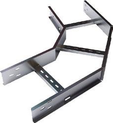
19 CABLE LADDER SYSTEMS Product footprint Cable ladder tray accessory foot print standard radius is 300 mm. 90 Degree Flat Bend Crossover Equal Tee Unequal Tee Outside Riser Central, right, or left hand reducer 18
20 NEMA VE1 / SELECTION PROCESS The following factors shall be considered when determining the appropriate Cable Trays Systems: Materials and Finishes Types of Cable Trays NEMA Classification NEMA Classes Cavity Size Load Depth/ of Tray NEMA CLASSIFICATION The National Electrical Manufacturers Association (NEMA VE-1) USA, classifications for Cable Trays were established to simplify and standardize the specifications of Cable Trays. This classification is based on the working load (the total weight of the cables), and the support span (the distance between supports). Cable Load/Working Load The Cable load or the working load is the total weight of the cables to be placed in the tray. The NEMA classes are based on cable loads of 50Lbs/Ft., (74 kg/m), 75Lbs/Ft. (112 kg/m), and 100Lbs/Ft. (149 kg/m). This is the total weight of cables in the tray. For purposes of selecting a suitable tray, this weight shall be rounded off to the next higher NEMA working (allowable) load. Support Spans Support span is the distance between the supports. The NEMA standard support spans are based on 8 (2.4m), 12 (3.7m), 16 (4.9m) and 20 (6.0m). NEMA CLASSES The following table summarizes the NEMA classes based on cable/working load and support span described previously. Table 1 NEMA Load/Span Designations Class Designation Support Span Feet Working Load Feet m Lbs./Ft. Kg/m 8A B C A B C A B C A B C D
 of the top flange.")
21 NEMA CLASSES Other Loading Considerations Destruction Load Capacity The total weight in the tray which causes the tray to collapse, is called the destruction load capacity. When trays do collapse, they generally do so by premature lateral buckling (compression) of the top flange. Concentrated Loads A concentrated load is a static weight applied between the side rails at mid span. When specified, these concentrated static loads may be converted to an equivalent uniform load (We), in pounds per linear foot or Kg/m, using the following formula: We = 2 x Concentrated Load Support Span in mm This load is added to the static weight of the cable before selecting the appropriate NEMA load span designation. Please note per the NEMA VE-1 guidelines all SFSP Cable Ladder Trays are labeled as follows: WARNING!! DO NOT USE AS A WALKWAY, LADDER OR SUPPORT FOR PERSONNEL. TO BE USED ONLY AS A MECHANICAL SUPPORT FOR CABLES AND TUBING. Order Reference: SFSP0010 CL Part Number : CTMCL C NEMA VE-1 LOAD CLASS Cable Tray Systems Safety Factor All loads stated in the selection charts have a 1.5 safety factor, in accordance with the NEMA VE-1 guidelines. A safety factor is the reserve strength, above the actual cable loading, for which a tray system was designed. Conversion of Safety Factor from 1.5 to 2.0 The loads stated in the selection charts have a safety factor of 1.5 per the NEMA VE-1 guidelines. To convert the load carrying capabilities, as listed in these charts, to a 2.0 safety factor, multiply the stated loads by Testing Methods Loading data stated in the catalogue have been derived from actual testing of the tray systems, or by means of structural calculations. These figures are based on simple beam calculation, per the NEMA VE-1 guidelines. 20
 is compressed. Material below, is stretched and is in tension. The maximum stress in a simple beam is at the center of the span.")
22 When tray is supported as a simple beam, the load causes bending moments all along the beam resulting in deflection, called sag, inducing stress in the beam. The material above the longitudinal center line (neutral axis) is compressed. Material below, is stretched and is in tension. The maximum stress in a simple beam is at the center of the span. Failure of Cable Trays will occur in compression before tension. This is why tray rails often have stiffened top flanges. A simple beam is present when a single straight section of tray is supported on each end. When a series of straight sections are connected and supported by more than one support it is referred to as a continuous beam. The NEMA VE-1 standards consider only a simple beam for testing purposes, due to the following reasons: 1. It requires maximum properties for a given load and support spacing. 2. It is the easiest when it comes to approximation by calculation. 3. It represents the most severe or worst case loading. 4. Destruction load capacities can be easily verified. Deflection vs. Economy Cable Ladder Trays meet all performance and dimensional criteria with safety factor. When deflection limitations are imposed, a less economical tray system may result. If deflection is a concern, SFSP recommends these maximum limits for the optimum design. DEFLECTION Neutral Axis DEFLECTION Table 2 Simple Beam Span )m 3.60( 12 )m 6.00( 20 STEEL 1/100 1/75 ALUMINUM 1/75 1/50 Continuous beams (such as installed tray) deflect approximately as much as 1 2 of Welded Cable Ladder Trays of simple beams. 21
23 CAVITY SIZE LOAD DEPTH/WIDTH OF TRAY Select the Fittings Fittings are used to change the size or direction of the Cable Ladder Trays. The most important decision to be made in fitting design concerns radius. The radius of the bend, whether horizontal or vertical, can be 305mm, 607mm, 914mm and 1219 mm, or even greater on a custom basis. The selection requires a compromise with the considerations being available space, minimum bending radius of cables, ease of cable pulling, and cost. The typical radius is 607mm. When a standard angle will not work, field fittings or adjustable elbows can be used. It may be necessary to add supports to the tray at these points. Refer to NEMA VE2 Installation Guidelines for suggested support locations. Note that fittings are not subject to NEMA/CSA load ratings. 22
24 Location of Couplings Since different bending moments are created in each span, there is no simple factor to approximate deflection as the number of spans increases. It is possible to calculate these deflections at any given point by using second integration of the basic differential equation for beams. Testing shows that the center span of a three-tray continuous beam can deflect less than 10 % of its simple beam deflection. Couplers at 1/4 from Support Span The support span cant be greater than the straight section length, to ensure no more than one splice is located between supports. Location of Couplers. The location of the coupler dramatically affects the deflection of a Cable Ladder Trays System under equal loading conditions. Testing indicates that the maximum deflection of the center span of a three-span tray run can decrease four times if the couplers are moved from one-quarter span to above the supports. This can be a major concern for designers considering modular systems for tray and pipe racks. Support Locations for Fittings 1/4 span L L L LENGTHS OF STRAIGHT SECTIONS Cable Ladder Trays are available in 12 (3.7m) and 24 (7.4m) lengths in accordance with the NEMA Standards. Customized lengths are also available upon request. The following factors need to be considered when specifying the lengths of the trays: Support Span The support span shall not be greater than the tray length. This ensures that the two splice plate connections will not fall within one support span. Space Constraints When installing trays in a limited space, as often encountered in commercial applications, 10 (3.0m) and 12 (3.7m) lengths of tray are easier to handle and therefore are better suited for those applications. Labor Costs Where trays are being installed in an industrial facility, where space is not a significant issue, handling 20 (6.1m) and 24 (7.4m) lengths may be more economical. In this instance, half as many tray connections need to be made. Additionally, if the proper tray system is specified, support spans may be lengthened. 23
25 RADIUS OF FITTINGS Cable Ladder Tray fittings are used to change directions both horizontally and vertically. The standard radii for Cable Ladder Tray fittings are 12 (305mm), 24 (610mm), and 36 (915mm). The radii of the fittings shall be based upon minimum bending radius of the cables. This information can be obtained from the cable manufacturer. Based on the total number of cables to be placed in the tray it may be more practical to use the next higher radius. CABLE LADDER TRAY SUPPORT POSITIONS Straight Sections A general rule of thumb is that the splice plates shall not fall beyond the 1 4 point of the span, or the distance between supports. For example: On a 20 (6.1m) support span, the splice plates shall not be further than 5 (1.5m) away from the support location. Under no circumstances shall two Cable Ladder Tray splices fall between any pair of supports. For special applications, mid-span splice plates can be furnished. Please contact the factory. Fittings Supports for Cable Ladder Tray elbows are critical. It is important to note that the Cable Ladder Tray will come under its greatest stress when cables are being pulled into the tray. Therefore, proper placement of supports is necessary to ensure that the integrity of the tray system is maintained during the cable pulling operation. The diagrams on page 2-10 show the recommended support locations for fittings. Thermal Expansion and Contraction It is important to use expansion connectors when installing long runs of Cable Ladder Trays. The number of expansion connectors required will depend on: (1) the maximum temperature difference (2) the tray material being installed Expansion Connectors allow 1 (2.5cm) of travel. This table illustrates how often expansion splice plates shall be used. Expansion Splice Plate Regular Splice Plate Expansion Splice Plate Expansion Guides Firm Hold-Down Expansion Guides 24
26 CABLE LADDER TRAY SUPPORT POSITIONS The below mentioned table is used to determine the proper gap setting between trays. The metal temperature determines the proper gap setting at the time of installation. Establish maximum and minimum temperatures in summer and winter for the area. Draw a line connecting them. Using the metal temperature at time of installation (C or F ) draw a horizontal to temperature slope and plot straight down to find the gap distance at expansion joint. This diagram illustrates the proper installation of an expansion system. It is important to note that Cable Ladder Trays grounding straps are required when expansion connections are made. This will ensure proper grounding continuity. MAX. TEMP MIN. TEMP METAL TEMPERATURE AT TIME OF INSTALLATION (FO or CO) TEMPERATURE SLOPE GAP SETTING, INCHES (MM) C O F O 0 1/8 1/4 3/8 1/2 5/8 3/4 7/8 1 (0.0) (3.2) (6.3) (9.5) (12.7) (15.9) (19.0) (22.2) (25.4) Temperature Difference Distance between Expansion Joints Steel Aluminum Copper 25 F (14 C) 512 (156m) 260 (79m) 363 (111m) 50 F (28 C) 256 (78m) 130 (40m) 182 (55m) 75 F (42 C) 171 (52m) 87 (27m) 121 (37m) 100 F (56 C) 128 (39m) 65 (20m) 90 (27m) Table F (70 C) 102' (31m) 52 (16m) 72 (22m) 150 F (83 C) 85 (26m) 43 (13m) 60 (18m) 175 F (97 C) 73 (22m) 37 (11m) 52 (16m) 25
27 ELECTRICAL GROUNDING NEC (ANSI / NFPA 70), Article allows for Cable Trays to be used as an equipment grounding conductor in commercial and industrial establishments. The following table lists specific ampere ratings and the minimum cross sectional area requirements for each rating. SFSP produces Cable Tray Systems which meet the National Electrical Code (ANSI/NFPA 70), these can be used for any project worldwide except where another standard may take precedence, such as the Canadian Standards Association (CSA). When required, Cable Trays can be installed per the Canadian Electrical Code Parts I and II (CEC). Trays and splice plates meet the bonding requirements of the CSA Standards and the CEC. The cross-sectional area for each Cable Trays System, straight sections and fittings can be found on the appropriate selection charts contained within this publication. In addition, all Cable Trays, straight sections and fittings are supplied with pressure sensitive labels indicating the cross sectional area of both side rails, as required by the (NEC) National Electrical Code. Table 4 Max. Fuse Amp Rating Circuit Breaker Amp Trip Setting or Relay Amp Trip Setting for Ground Fault Protection of any Cable Trays Circuit In the Cable Trays Systems Minimum Cross Sectional Area of Metal* Steel Cable Trays Aluminum Cable Trays In 2 mm 2 In 2 mm ** , , , , ** 1,290 *Total cross sectional area of both side rails for ladder trough type trays, or the minimum cross-sectional area for metal in channel type Cable Trays or Cable Trays of one piece construction. Bonding Jumpers / Straps Cable Tray connections made with standard rigid splice plates, these rigid type connections do not require electrical bonding straps. Electrical bonding straps are required where Cable Trays are joined by connectors which allow movement, such as: vertical adjustable connectors, horizontal adjustable connectors and expansion connectors. Proper grounding is also necessary where Cable Trays run parallel to each other, are stacked upon one another and in other instances where tray runs are discontinuous. Summary You are now ready to select the best Cable Trays System to meet your needs. By now, we hope you ve decided to select the system using the NEMA CLASSIFICATION (8A, 12B, 20C, etc.) which makes your work so much easier. Selection is also possible using physical dimensions, performance or any combination of these data listed NEMA oriented. 26
28 CABLE SPECIFICATIONS Most cable manufacturers offer a very accurate method of calculating cable weights, and appropriates lists or tables can be obtained from them. Important: The tables only provide a rough overview. They are average values, which may vary from manufacturer to manufacturer. Please refer to the manufacturer s specifications for the exact values. Actual cable weights of different cable types Insulated power cables Insulated power cables Telecommunication Cables Type Cable load kg/m Type Cable load kg/m Type Cable load kg/m Type Cable load kg/m 1 x x x x 2 x 0, x x x x 2 x 0, x x x x 2 x 0, x x x x 2 x 0, x x x x 2 x 0, x x x x 2 x 0, x x x x 2 x 0, x x x 1, x 2 x 0, x x x 2, x 2 x 0, x x x x 2 x 0, x x x x 2 x 0, x x x x 2 x 0, x x 1, x x 2 x 0, x x 2, x x 2 x 0, x x x x 2 x 0, x x x 2 x 0, x x x 2 x 0, x x x 2 x 0, x x x x 1, x x 2, x x x x x x x x IT cables type cat Type Cable load kg/m Coax cable (Standard) Type Cable load kg/m Cat. 5/Cat SAT/BK cable
29 CABLE SPECIFICATIONS External diameter and cross section Type Insulated power cables Insulated power cables Telecommunication Cables Ø mm Useful crosssection cm² Type Ø mm Useful crosssection cm² Type Ø mm Useful cross-section cm² 1 x x x 2 x 0, x x x 2 x 0, x x x 2 x 0, x x x 2 x 0, x x x 2 x 0, x x x 2 x 0, x x x 2 x 0, x x x 2 x 0, x x x 2 x 0, x x x 2 x 0, x x x 2 x 0, x x x 2 x 0, x x 1, x 2 x 0, x x 2, x 2 x 0, x x x 2 x 0, x x x 2 x 0, x x x 2 x 0, x x x 2 x 0, x x x x 1, x x 2, x x x x x x x x x x x x x x x x x 1, x 2, x x x x x x
30 The choice is made under consideration of: 1- The number of cable to be passed in a Cable Tray (Load carrying capacity of the tray). 2- The load of cable to be passed in a cable tray and support distance. Cable Capacity For the estimation of cable area, the table shown below is used to help. Table 1 Space needed for cable to type NYY for example: Cable Diameter Area per cable x Number of cable Usable area NYY mm cm² cm² 4 x 1,5 12,5 1,5 x 1 1,5 4 x 2,5 14,0 1,8 x 1 1,8 4 x 6,0 16,5 3,0 x 1 3,0 4 x ,0 x 1 5,0 4 x ,0 x 1 12,0 4 x ,0 x 1 16,0 A 39,30 cm² For cables of any size the area per cable is multiplied with the number of cables, whereas the sum(a) is the total area of the cables. The result is the needed cross section area of the Cable Tray. Example For the cable shown in table 1 (using 1 cable of each type) we need min. a Cable tray of 40.0 cm². Table 2 Weight of cables type NYY (Power Cable) Cable Cable weight Number of Total weight x = NYY N/m Cables (variable) N/m 4 x 1,5 1,6 x 1 = 1,6 4 x 2,5 2,3 x 1 = 2,3 4 x 6,0 4,6 x 1 = 4,6 4 x 16 10,9 x 1 = 10,9 4 x 35 20,9 x 1 = 20,9 4 x 70 31,0 x 1 = 31,0 Cable Load F = 71,3 N/m Cable Weight To determine the total weight, each cable weight is multiplied with the its number. The result is the estimated cable load (F). The highest possible cable load is decisive. This is calculated by multiplication of the usable diameter with the specific cable weight. According to DIN VDE 0639 Type of Cable Support Cable Specific Cable weight Cable Ladder Control line cables Usable section x 2,8N/m x cm² Cable Tray Voltage line cables Usable sectionx1,5 N/m x cm² Supporting structures In order to choose construction pieced of sufficient weight load ability, the load of each Cable Tray or Cable Ladder at the support point has to be determined. The supporting structures for Cable Tray or Cable Ladder contain a) On walls: bracket support or wall bracket b) On ceiling: ceiling bracket support 29
31 CABLE LADDER TRAYS SYSTEM DESIGN Nomenclature 1. Cable Ladder Trays 2. Ventilated Cable Ladder Trays 3. Joint Plate / Fish Plate Horizontal Bend Horizontal Bend 6. Horizontal Tee 7. Horizontal Cross Vertical Outside Bend Vertical Outside Bend Vertical Inside Bend 11. Vertical Bend 12. Vertical Tee 13. Left Reducer 14. Frame Type Box Connector 15. Barrier Strip 16. Solid Flanged Tray Cover 17. Channel Straight Section 18. Channel Cable Ladder Trays, 90 Vertical Outside 19. Expansion Connectors
32
33 ALUMINUM SWAGED TUBULAR CABLE LADDER TRAYS Is a structure consisting of two side rails, connected by individual rungs and is manufactured in accordance with NEMA Standard #VE-1. Rungs are fastened to the side members by an exclusive swaging process. This assembly method ensures a superior mechanical and electrical connection. RUNG SPACING (center-to-center) RUNG LOAD DEPTH SIDE RAIL TOP FLANGE (stiffened type shown) SIDE RAIL SIDE RAIL HEIGHT WIDTH LENGTH BOTTOM FLANGE Side Members Side members are designed with top and bottom flanges turned outwards. This simplifies fastening the Cable Ladder Trays to the supports. Cable Ladder Trays with outward facing flanges allow complete access within the cable loading area and eliminate the possibility of cable damage from sharp edges within the cable area. The return on the top flange strengthens the side member and allows cables to be smoothly dropped over the side. Rung Ladder rungs are 1.00 (25mm) diameter tubings flattened on top to provide a cable bearing surface. This construction allows cables to drop out anywhere without contacting a sharp edge. Rung Spacing The interval at which rungs are swaged to the side member. This is measured from center line of rung to center line of rung. SFSP manufactures straight lengths with four standard rung spacings: 6 (150mm), 9 (229mm), 12 (305mm) and 18 (457mm). Rung spacing is generally determined by the size and type of the cable being supported. When in doubt, 9 (229mm) rung spacing is a generally accepted compromise. Length The longitudinal dimensions of standard Cable Ladder Trays are 10 (3.0m), 12 (3.7m), 20 (6.1m) and 24 (7.4m). The transverse dimensions of Cable Ladder Trays are measured inside (from side member web to side member web) and are furnished in seven standard widths: 6 (150mm), 9 (229mm), 12 (305mm), 18 (457mm), 24 (610mm), 30 (750mm) and 36 (915mm). Overall Overall ladder width is equal to the inside or nominal width plus the width of the side member flanges. 32
34 Load Depth Measured from top surface of rung to the top of the side member. This is not to be confused with the overall height. SFSP manufactures four loading depths: 3 (75mm), 4 (100mm), 5 (125mm) and 6 (150mm) in accordance with NEMA Standard VE-1. Overall Height Overall height is equal to the loading depth plus 1.25 (30mm). Fittings For changing direction horizontally and vertically, SFSP manufactures elbows, tees and crosses in all widths and loading depths. Fittings are available in three standard radii; 12 (305mm), 24 (610mm) and 36 (915mm). Maintain a nominal 9 (229mm) rung spacing through the center line of all fittings. Swaged Rounded Tubular Cable Ladder Trays Features: 1. Universal Curvilinear Splice Plate System The splice plates for rigid connections have a slight curve so that they can be used on straight sections or fittings. Tightening of the fastener pulls the plate flush with the side rail,which makes the fasteners snug and the joint becomes superior structurally and electrically. Even when hand-tight, there is pressure on the fastener to hold it securely. Note: Heavy Duty and Mid Span Splice Plates are available upon request. 2. New Zero Tangent Fittings Tangent as referred to on Cable Ladder Trays fittings is the straight part at the end of the curve to accommodate a flat splice plate. This wastes space in tightly packed areas, such as spreader rooms, where the heat of thousands of cables accumulate. Eliminating tangents allows more tray runs to distribute the heat. Zero tangent fittings can save up to 12 (3.7m) per row of tray. 3. Swaged Rung Cable Ladder Trays System Process The heart of the design is the tubular rung and its connection to the side rail by cold swaging, a process where special machinery compresses and locks the tubular rung material around both the inside and outside of the Cable Trays side rails. This connection is made without the use of heat which can potentially disturb the molecular structure of the metal and weaken it. The tubular rung is flattened during the swaging process to ensure a proper cable bearing surface. Swage Advantages Swaging allows the side rails to be turned outwards, simplifying cable installation and providing 100% access to the cables. Cold swaging yields the most rigid tray systems in the industry. The swaged rung connection resists stresses in all directions: up or down, side to side or in and out. The swaged ladder also resists the camber and warping effects encountered in a typical welde system. The increased rigidity means that a 24 (7.4m) section of tray can be lifted on one end with little or no twisting or bending of the tray section. This rigid construction makes the trays safer for field personnel to handle and reduces shipping damage. Electrical Properties Electrically, the 106 tons of pressure in the swaging process virtually eliminates the interstices and a homogenous electrical path results in the following: Resistance of Aluminum Swaged Tray: 31 microhms Resistance of Steel Swaged Tray: 37.3 microhms Resistance of Popular Aluminum Welded Tray: 101 microhms Conclusion Cold swaging yields a very strong, efficient and aesthetically pleasing system that stands the test of time and offers installation savings due to its ease of handling. 33
35 STEEL CABLE LADDER TRAYS Is a prefabricated metal structure consisting of reinforced Welded Cable Ladder Trays -shaped rungs, arc welded to the side rails and is manufactured according to NEMA Standard VE-1. Welded Cable Ladder Trays rungs are fastened to the side rails with an automatic, self-indexing MIG-arc-welding system, plug welding a 0.5 (12.5mm) diameter zone. The superior strength of the plug weld withstands the rigors of shipping, handling, erection and cable support service. Side Members Welded Cable Ladder Trays side members are designed with top and bottom flanges turned inwards. This minimizes the space requirements of the Cable Trays Systems, and allows a very low side rail height for each NEMA Standard VE-1 load depth. Slotted Rungs Slotted shaped rungs are provided on trays 6 (150mm), 9 (229mm), 12 (305mm), 18 (457mm) and 24 (610mm) wide. All slotted rungs are 2.5 (63mm), and provide a 1.25 (30mm) cable bearing surface. Slots provide a neat, convenient option for cable tie down requirements. Slots are 5 16 (6.25mm) wide and 5 8 (12.5mm) in length, and are located on 1 (25mm) centers across the entire width of the rung Solid Rungs Solid shaped Rungs are provided on trays 30 (750mm) and 36 (915mm) wide. Solid Rungs for steel trays are 2.25 (58mm) wide and provide a 7 8 (22mm) cable bearing surface. Rung Spacing SFSP manufactures straight lengths with four standard rung spacings; 6 (150mm), 9 (229mm), 12 (305mm) and 18 (457mm). The 6 (150mm) rung spacing results in a 3.75 (94mm) opening between rungs allowing the tray to be classified as a ventilated trough per NEMA Standard VE-1. Length The longitudinal dimensions of standard Welded Cable Ladder Trays are 10 (3.0m), 12 (3.7m), 20 (6.1m) and 24 (7.4m). The transverse dimensions of Welded Cable Ladder Trays are measured from the inside and are furnished in seven standard widths: 6 (150mm), 9 (229mm), 12 (305mm), 18 (457mm), 24 (610mm), 30 (750mm) and 36 (915mm). Overall Overall tray width is equal to the inside or nominal width plus the thickness of the two side rail webs. Overall Tray = Nominal (5mm). Load Depth Measured from the top surface of the rungs to the top of the side member. SFSP manufactures four load depths; (73mm), (101mm), (127mm) and (153mm) corresponding to the four nominal load depths in NEMA Standard 1 (25mm), 3 (75mm), 4 (100mm), 5 (125mm) and 6 (150mm). Overall Height Welded Cable Ladder Trays overall height is equal to the load depth plus 1.25 (30mm). Fittings For changing direction both horizontally and vertically, SFSP manufactures tees and crosses in all widths and load depths. Standard fittings maintain a nominal 9 (229mm) rung spacing through the center line of the fitting. C-Channel Rung Upside Tubular Rung Rounded Tubular Rung Slotted C-Channel Rung Downside 34
36 Welded Ladder Cable Tray Features: 1. Compact Economical System Welded Cable Ladder Trays are an extremely compact economical flange in Cable Trays Systems which allow the designer to utilize these Cable Trays in tight locations. The extremely low profile Welded Cable Ladder Trays Rungs (5 8 high) minimize the required side rail height while maintaining NEMA Standard VE-1 nominal load depths. Overall system height is only 5 8 greater than the actual load depth. 2. Universal Curvilinear Splice Plate System The splice plates for rigid connections have a slight curve so they can be used on straight sections or fittings. Tightening of the fastener pulls the plate flush with the side rail. The fasteners are snug and the joint is superior structurally and electrically. Even when hand-tight, there is pressure on the fastener to hold it securely. Note: Heavy Duty and Mid Span Splice Plates are available upon request. 3. Zero Tangent Fittings Tangent as referred to on Cable Tray fittings is the straight part at the end of the curve to accommodate a flat splice plate. This wastes space in tightly packed areas, such as spreader rooms, where the heat of thousands of cables accumulate. Eliminating tangents allows more tray runs to distribute the heat. Inspection of proper installation of splice plates is done visually. If the plate is bowed away from the rail, nuts shall be tightened. 4. Welded Assembly System Welded Cable Ladder Trays rungs on straight sections are assembled to the side rails using an automatic, these welds are 700% larger and stronger than the common resistance (spot) weld in use today. Electrical properties of the assembly are unequalled; are well within the NEMA requirements due to the continuous electrical path. The mechanical strength of this welded assembly withstands the rigors of shipping, handling, erection and service. The size of the weld keeps the vertical axis of the side rail from sloping inwards under load. The weld maintains the 90 angle between the side rail and bottom. This allows full use of the section properties. Spot welds do not permit this. Also, stresses on spot welds (barely 1 8 (3mm) in diameter) are so severe that breakage often occurs during shipping and erection. Welded Cable Ladder Trays fittings are also assembled by MIG-arc welding. 35
37 CABLE LADDER TRAY SYSTEMS OVERVIEW SFSP s Cable Ladder Trays Systems are available in a variety of finishes, and in varying width and load depth for many applications including primary service entrances, main power feeders, branch wirings, instruments and communications cables. Applications: - Industrial: Gas facilities, Oil facilities, Power Plants, Petrochemical Plants, Automotive Plants, Paper Plants, Food Processing, Power Plants, Refineries, Manufacturing, Mining. - Commercial: Shopping Centers, Control Buildings, Schools, Hospitals, Office Buildings, Airports, Stadiums Features: Rounded side rail flanges protect cables. All designs permit easy cable dropout with no sharp edges to damage insulation. Slotted C-Channel rungs allow simple cable fastening. High strength splices allow random locations between supports (full sections used on all simple beams). Standard straight section length is 3000 mm. Complete line of fittings and accessories. Cable Ladder Trays consist of two longitudinal side rails connected by rungs. SFSP designs are very popular due to their versatility and low costs. They also provide: maximum ventilation for conductor cooling, smooth edges on side rails and rungs to protect cables and slots for easy cable fastening when required. Various rung spacings are available to provide support for most cables, from small flexible cables to the most rigid interlocked armor power cable. SWAGED CABLE LADDER TRAYS (ALUMINUM) Aluminum 6063 T6 - Side Rails Design Data Aluminum 6063 T6 Load Classes Side Rail Height (mm) Load Depth Fd (mm) Thickness (mm) F (mm) W cm 3 I cm 4 Side Rail Load kg/m Span (m) Classes NEMA A A A A A A A C A A A B SFSP s Swaged Cable Ladder Trays consist of 2 outside rails that are connected by a round tubular rung of 25 mm outside diameter. SFSP s Swaged Cable Ladder Trays are manufactured in widths (w): 150 mm, 225 mm, 300 mm, 450 mm, 500 mm, 600 mm, 750 mm and 900 mm. Other dimensions are available upon request. Tubular Rungs The available distance spacing (S) between the rungs is 229 mm. Length (L): 2440/3000 mm. Side height of the side rail is 110 mm, 136 mm, 162 mm and 188 mm. Other dimensions are available upon request. Swaged Cable Ladder Trays are available in: Aluminum 6063 T6 Rail L x Tubular Rounded Rung x S 36
38 SWAGED CABLE LADDER TRAYS (ALUMINUM) (153 mm) (127 mm) (101 mm) (75 mm) C Type Swaged connections make the most rigid tray system in the industry. The swaging process does not affect the temper and strength of surrounding metal the way that traditional welding does. 37
39 SWAGED CABLE LADDER TRAYS (ALUMINUM) Aluminum Cable Ladder Trays - General Overview L A C.Ladder Side Rail 6 C.Ladder Side Rail C.Ladder Side Rail 4 C.Ladder Side Rail SFSP can make modifications and design materials or finishes as it deems necessary or desirable. All illustrations, drawings and descriptive material in this publication are of a generally informative nature only, and do not form a complete package of the specifications or description of the goods. Most of the dimensions shown are nominal. 38
 Rounded tubular with 25 mm diameter Rung")

 Slotted")

40 STEEL CABLE LADDER TRAYS (STEEL S235 JRG2) RUNG TYPES (Swaged and Channel) Swaged Type (Aluminum & Steel) Rounded tubular with 25 mm diameter Rung standard spacing 229 mm Channel Type (Steel) Plain or slotted, and can be mounted upwards or downwards. Rung standard spacing 229 mm RAIL TYPES Types of Rail: C-Type, Z-Type and R-Type Rounded Tubular - Swaged or Welded Plain Channel (Steel) Slotted Channel (Steel) Z-Type C-Type R-Type MATERIALS Pre-Galvanized / Stainless Steel FINISHES Hot-Dip Galvanized, Zinc Electroplating and Epoxy Powder Coating. MATERIAL THICKNESS 1.50 mm 2.00 mm 2.50 mm 39
41 STEEL CABLE LADDER TRAYS - GENERAL OVERVIEW Tubular Rounded Rung 25mm diameter X 1.5mm thickness (t) RUNG L W SIDE RAIL S S Rung Types and Dimensions Rung Thicknesses: 1.5 mm, 2.0 mm and 2.5mm 21 Downwards 50 mm 13 X 30 mm 41 Upwards (slots only upon request ) 40
42 Length and Rung Spacing Side Rail Types Height of rail 50mm - 150mm All Units are in (mm) 41
43
44 CABLE LADDER TRAY RUNS
45 44
46 SWAGED TUBULAR RUNG ALUMINUM 6063 T6 NEMA Class A (52 kg/m by 3.0m) and 8A (95 kg/m by 2.40m) NEMA Class C (97.0 kg/m by 3.0 m) NEMA Class 12 A (74 kg/m by 3.70 m) NEMA Class 12 B (134 kg/m by 3.70 m) F T Side Height Load Depth Tubular Rung Aluminum 6063 T6 - Side Rails Design Data Side Rail Height (mm) Load Depth Fd (mm) Thickness (mm) A A A A F (mm) W cm 3 I cm 4 Load Classes Side Rail Load kg/m Span (m) Classes NEMA A A A C A A A B 45
 - NEMA Class A (52 kg/m by 3,0m) and 8A (95 kg/m by 2,40m) - Side Rail: A1 - Height: 110 mm - Load Depth:")
 - (w) - Side type Other dimensions can be manufactured and supplied upon request.")
47 ALT - A1 (SWAGED ROUNDED TUBULAR) 2.00 mm Thickness (Side Height 110 mm) - NEMA Class A (52 kg/m by 3,0m) and 8A (95 kg/m by 2,40m) - Side Rail: A1 - Height: 110 mm - Load Depth: 82 mm - Rung Spacing: 229 mm 110 Tubular Rounded Rung W L All Units are in (mm) Side Height: 110 Load Depth: Tubular Rung Order Example: ALT - A1 - Side height (h) - (w) - Side type Other dimensions can be manufactured and supplied upon request. For more ordering details, please check page 134 )mm( Order Example Item (h) (w) Type 150 ALT - A C 225 ALT - A C 46
48 NEMA CLASS A Support Distance Load Rung Deflection (mm) (m) KN/m (mm) (mm) Rail Side Rail A X 20 X Rung 25x1.5 mm
 - Side Rail: A2 - Height: 138 mm - Load Depth: 108 mm - Rung Spacing: 229 mm 138 Tubular Rounded Rung 20 9.5 W L All Units are in (mm) Side Height: 138 Load Depth: 108 2.")
49 ALT - A2 (SWAGED ROUNDED TUBULAR) 2.00 mm Thickness (Side Height 138 mm) - NEMA Class C (97.0 kg/m by 3.0 m) - Side Rail: A2 - Height: 138 mm - Load Depth: 108 mm - Rung Spacing: 229 mm 138 Tubular Rounded Rung W L All Units are in (mm) Side Height: 138 Load Depth: Tubular Rung Order Example: ALT - A2 - Side height (h) - (w) - Side type Other dimensions can be manufactured and supplied upon request. For more ordering details, please check page 134 )mm( Order Example Item (h) (w) Type 150 ALT - A C 225 ALT - A C 48
50 NEMA CLASS A Support Distance Load Rung Deflection Rail (mm) (m) KN/m (mm) (mm) Side Rail A Tubular Rung: 25x1.5 mm 138 X 20 X Tubular Rung: 25x2.0 mm Tubular Rung: 30x1.5 mm 49
 - Side Rail: A3 - Height: 162 mm - Load Depth: 132 mm - Rung Spacing: 229 mm 162 Tubular Rounded Rung 20 9.")
 - (w) - Side type Other dimensions can be manufactured and supplied upon request.")
51 ALT - A3 (SWAGED ROUNDED TUBULAR) 2.00 mm Thickness (Side Height 162 mm) - NEMA Class 12 A (74 kg/m by 3.70 m) - Side Rail: A3 - Height: 162 mm - Load Depth: 132 mm - Rung Spacing: 229 mm 162 Tubular Rounded Rung W L All Units are in (mm) Side Height: 162 Load Depth: Tubular Rung Order Example: ALT - A3 - Side height (h) - (w) - Side type Other dimensions can be manufactured and supplied upon request. For more ordering details, please check page 134 )mm( Order Example Item (h) (w) Type 150 ALT - A C 225 ALT - A C 50
52 NEMA CLASS A Support Distance Load Rung Deflection Rail (mm) (m) KN/m (mm) (mm) Side Rail A Tubular Rung: 25x1.5 mm 162 X 20 X Tubular Rung: 25x2.0 mm Tubular Rung: 30x1.5 mm 51
53 ALT - A4 (SWAGED ROUNDED TUBULAR) 2.50 mm Thickness (Side Height 188 mm) - NEMA Class 12 B (134 kg/m by 3.70 m) - Side Rail: A4 - Height: 188 mm - Load Depth: 158 mm - Rung Spacing: 229 mm 188 Tubular Rounded Rung W L All Units are in (mm) Side Height: 188 Load Depth: Tubular Rung Order Example: ALT - A4 - Side height (h) - (w) - Side type Other dimensions can be manufactured and supplied upon request. For more ordering details, please check page 134 )mm( Order Example Item (h) (w) Type 150 ALT - A C 225 ALT - A C 52
54 NEMA CLASS A Support Distance Load Rung Deflection Rail (mm) (m) KN/m (mm) (mm) Side Rail A Tubular Rung: 25x1.5 mm X 20 X Tubular Rung: 25x2.0 mm Tubular Rung: 30x1.5 mm Tubular Rung: 30x2.0 mm
 159.")
55 ALT - A5 (SWAGED ROUNDED TUBULAR) 2.65 mm Thickness (Side Height mm) - NEMA Class 20 C (149 kg/m) - Side Rail: A5 - Height: mm - Thickness 2.65 mm - Load Depth: 127 mm - Rung Spacing: 229 mm - Length: 6 Meter All Units are in (mm) Tubular Rounded Rung W L Order Example: - Allowable TENSILE STRESS 145 N/mm² = 14,5 kn/cm² -Short support + big width = Rung decisive - Long support + short width = Rail decisive For more ordering details, please check page
56 NEMA CLASS A Support Distance Load Rung Deflection Rail (mm) (m) KN/m (mm) (mm) x 45 x
57 56
58 SWAGED TUBULAR RUNG STEEL S235 JRG2 NEMA Class 8C (149 kg/m by 2.40m) NEMA Class 12A (74 kg/m by 3.70m) NEMA Class 12B (118 kg/m by 3.70m) NEMA Class 12A (74 kg/m by 3.70m) NEMA Class 12B (123 kg/m by 3.70m) NEMA Class 16A (82 kg/m by 4.90m) NEMA Class 12A (87 kg/m by 3.70m) NEMA Class 12C (150 kg/m by 3.70m) NEMA Class D (67 kg/m by 6.0m) F T Side Height Load Depth Tubular Rung Steel S235 JRG2 - Side Rails Design Data Side Rail Classes Height Load Depth Thickness F W I NEMA (mm) Fd (mm) (mm) (mm) cm 3 cm 4 Span Class S A S B S A S A S C S D Load Classes Side Rail Load kg/m S A S B S A S A S C S D Span (m) Classes NEMA 57
59 SLT - S mm Thickness (Side Height 105 mm) - NEMA Class 12A (74 kg/m by 3.70m) - Side Rail: S1 - Height: 105 mm - Load Depth: 75 mm - Rung - Spacing: 229 mm 105 Tubular Rounded Rung W L All Units are in (mm) Side Height: 105 Load Depth: Tubular Rung Order Example: SLT - S1 - Side height (h) - (w) - Side type Other dimensions can be manufactured and supplied upon request. For more ordering details, please check page 134 )mm( Order Example Item (h) (w) Type 150 SLT - S C 225 SLT - S C 58
60 NEMA CLASS 12A Support Distance Load Rung Deflection Rail (mm) (m) KN/m (mm) (mm) Side Rail S X 20 X Tubular Rung: 25 X 1.5 mm
61 130 SLT - S mm Thickness (Side Height 130 mm) - NEMA Class 12B (123 kg/m by 3.70m) - Side Rail: S2 - Height: 130 mm - Load Depth: 100 mm - Rung Spacing: 229 mm Tubular Rounded Rung W L All Units are in (mm) Side Height: 130 Load Depth: Tubular Rung Order Example: SLT - S2 - Side height (h) - (w) - Side type Other dimensions can be manufactured and supplied upon request. For more ordering details, please check page 134 )mm( Order Example Item (h) (w) Type 150 SLT - S C 225 SLT - S C 60
62 NEMA CLASS 12A Support Distance Load Rung Deflection Rail (mm) (m) KN/m (mm) (mm) Side Rail S X 20 X Tubular Rung: 25 X 1.5 mm
63 SLT - S mm Thickness (Side Height 155 mm) - NEMA Class 16A (82 kg/m by 4.90m) - Side Rail: S3 - Height: 155 mm - Load Depth: 125 mm - Rung Spacing: 229 mm 155 Tubular Rounded Rung W L All Units are in (mm) Side Height: 155 Load Depth: Tubular Rung Order Example: SLT - S3 - Side height (h) - (w) - Side type Other dimensions can be manufactured and supplied upon request. For more ordering details, please check page 134 )mm( Order Example Item (h) (w) Type 150 SLT - S C 225 SLT - S C 62
64 NEMA CLASS 12A Support Distance Load Rung Deflection Rail (mm) (m) KN/m (mm) (mm) Side Rail S X 20 X Tubular Rung: 25 X 1.5 mm
65 SLT - S mm Thickness (Side Height 105 mm) - NEMA Class 12A (87 kg/m by 3.70m) - Side Rail: S4 - Height: 105 mm - Load Depth: 75 mm - Rung Spacing: 229 mm All Units are in (mm) 105 Tubular Rounded Rung W L Side Height: 105 Load Depth: Tubular Rung Order Example: SLT - S4 - Side height (h) - (w) - Side type Other dimensions can be manufactured and supplied upon request. For more ordering details, please check page 134 )mm( Order Example Item (h) (w) Type 150 SLT - S C 225 SLT - S C 64
66 NEMA CLASS 12A Support Distance Load Rung Deflection Rail (mm) (m) KN/m (mm) (mm) Side Rail S X 20 X Tubular Rung: 25 X 1.5 mm
67 SLT - S mm Thickness (Side Height 130 mm) - NEMA Class 12C (150 kg/m by 3.70m) - Side Rail: S5 - Height: 130 mm - Load Depth: 100 mm - Rung Spacing: 229 mm All Units are in (mm) 105 Tubular Rounded Rung W L Side Height: 130 Load Depth: Tubular Rung Order Example: SLT - S5 - Side height (h) - (w) - Side type Other dimensions can be manufactured and supplied upon request. For more ordering details, please check page 134 )mm( Order Example Item (h) (w) Type 150 SLT - S C 225 SLT - S C 66
68 NEMA CLASS 12A Support Distance Load Rung Deflection Rail (mm) (m) KN/m (mm) (mm) Side Rail S X 20 X Tubular Rung: 25 X 1.5 mm
 155 Tubular Rounded Rung W L Side Height: 155 Load Depth: 125 2.")
69 SLT - S mm Thickness (Side Height 155 mm) - NEMA Class D (67 kg/m by 6.0m) - Side Rail: S6 - Height: 155 mm - Load Depth: 125 mm - Rung - Spacing: 229 mm All Units are in (mm) 155 Tubular Rounded Rung W L Side Height: 155 Load Depth: Tubular Rung Order Example: SLT - S6 - Side height (h) - (w) - Side type Other dimensions can be manufactured and supplied upon request. For more ordering details, please check page 134 )mm( Order Example Item (h) (w) Type 150 SLT - S C 225 SLT - S C 68
70 NEMA CLASS 12A Support Distance Load Rung Deflection Rail (mm) (m) KN/m (mm) (mm) Side Rail S X 20 X Tubular Rung: 25 X 1.5 mm Tubular Rung: 25 X 2.0 mm
71 70
 NEMA Class 12B (123 kg/m by 3.70m) NEMA Class 16A (82 kg/m by 4.90m) NEMA Class 12A (87 kg/m by 3.70m) NEMA Class 12C (150 kg/m by 3.70m) NEMA Class D (67 kg/m by 6.")
72 WELDED C-CHANNEL - LADDER TYPE RUNS STEEL S235 JRG2 NEMA Class 8C (149 kg/m by 2.40m) NEMA Class 12A (74 kg/m by 3.70m) NEMA Class 12B (118 kg/m by 3.70m) NEMA Class 12A (74 kg/m by 3.70m) NEMA Class 12B (123 kg/m by 3.70m) NEMA Class 16A (82 kg/m by 4.90m) NEMA Class 12A (87 kg/m by 3.70m) NEMA Class 12C (150 kg/m by 3.70m) NEMA Class D (67 kg/m by 6.0m) F Side Height Load Depth T C.Channel 21x41 mm Steel S235 JRG2 - Side Rails Design Data Side Rail Classes Height Load Depth Thickness F W I NEMA (mm) Fd (mm) (mm) (mm) cm 3 cm 4 Span Class S A S B S A S A S C S D Load Classes Side Rail Load kg/m S A S B S A S A S C S D Span (m) Classes NEMA 71
 - Side Rail: S1 - Height: 105 mm - Load Depth: 75 mm - Rung - Spacing: 229 mm 20 All Units are in (mm) Side Height: 105 Load Depth: 75 2.0 C.")
73 SL - S mm Thickness (Side Height 105 mm) - NEMA Class 12A (74 kg/m by 3.70m) - Side Rail: S1 - Height: 105 mm - Load Depth: 75 mm - Rung - Spacing: 229 mm 20 All Units are in (mm) Side Height: 105 Load Depth: C.Channel 21X41 Order Example: SL - S1 - Side height (h) - (w) - Side type Other dimensions can be manufactured and supplied upon request. For more ordering details, please check page 134 )mm( Order Example Item (h) (w) Type 150 SL - S C 225 SL - S C 72
74 NEMA CLASS 12A Support Distance Load Rung Deflection Rail (mm) (m) KN/m (mm) (mm) Side Rail S X 20 X Rung 41 x 21 x 1.5 mm
75 SL - S mm Thickness (Side Height 130 mm) - NEMA Class 12B (123 kg/m by 3.70m) - Side Rail: S2 - Height: 130 mm - Load Depth: 100 mm - Rung Spacing: 229 mm 20 All Units are in (mm) Side Height: 130 Load Depth: C.Channel 21X41 Order Example: SL - S2 - Side height (h) - (w) - Side type Other dimensions can be manufactured and supplied upon request. For more ordering details, please check page 134 )mm( Order Example Item (h) (w) Type 150 SL - S C 225 SL - S C 74
76 NEMA CLASS 12A Support Distance Load Rung Deflection Rail (mm) (m) KN/m (mm) (mm) Side Rail S X 20 X Rung 41 x 21 x 1.5 mm
77 SL - S mm Thickness (Side Height 155 mm) - NEMA Class 16A (82 kg/m by 4.90m) - Side Rail: S3 - Height: 155 mm - Load Depth: 125 mm - Rung Spacing: 229 mm 20 All Units are in (mm) Side Height: 155 Load Depth: C.Channel 21X41 Order Example: SL - S3 - Side height (h) - (w) - Side type Other dimensions can be manufactured and supplied upon request. For more ordering details, please check page 134 )mm( Order Example Item (h) (w) Type 150 SL - S C 225 SL - S C 76
78 NEMA CLASS 12A Support Distance Load Rung Deflection Rail (mm) (m) KN/m (mm) (mm) Side Rail S Rung 41 x 21 x 1.5 mm 155 X 20 X Rung 41 x 41 x 1.5 mm Rung 41 x 41 x 1.5 mm Rung 41 x mm 77
79 SL - S mm Thickness (Side Height 105 mm) - NEMA Class 12A (87 kg/m by 3.70m) - Side Rail: S4 - Height: 105 mm - Load Depth: 75 mm - Rung Spacing: 229 mm 20 All Units are in (mm) Side Height: 105 Load Depth: C.Channel 21X41 Order Example: SL - S4 - Side height (h) - (w) - Side type Other dimensions can be manufactured and supplied upon request. For more ordering details, please check page 134 )mm( Order Example Item (h) (w) Type 150 SL - S C 225 SL - S C 78
80 NEMA CLASS 12A Support Distance Load Rung Deflection Rail (mm) (m) KN/m (mm) (mm) Side Rail S Rung 41 x 21 x 1.5 mm 130 X 20 X Rung 41 x 21 x 2.0 mm
 - Side Rail: S5 - Height: 130 mm - Load Depth: 100 mm - Rung Spacing: 229 mm 20 All Units are in (mm) Side Height: 130")
 - (w) - Side type Other dimensions can be manufactured and supplied")
81 SL - S mm Thickness (Side Height 130 mm) - NEMA Class 12C (150 kg/m by 3.70m) - Side Rail: S5 - Height: 130 mm - Load Depth: 100 mm - Rung Spacing: 229 mm 20 All Units are in (mm) Side Height: 130 Load Depth: C.Channel 21X41 Order Example: SL - S5 - Side height (h) - (w) - Side type Other dimensions can be manufactured and supplied upon request. For more ordering details, please check page 134 )mm( Order Example Item (h) (w) Type 150 SL - S C 225 SL - S C 80
82 NEMA CLASS 12A Support Distance Load Rung Deflection Rail (mm) (m) KN/m (mm) (mm) Side Rail S Rung 41 x 21 x 1.5 mm 130 X 20 X Rung 41 x 21 x 2.0 mm Rung 41 x 41 x 1.5 mm Rung 41 x 21 x 2.0 mm 81
 - NEMA Class Steel S9 - Side Rail: S6 - Height: 155 mm - Load Depth: 125 mm - Rung Spacing: 229 mm 20 All Units are in (mm) Side Height: 155 Load Depth: 125 2.5 C.")
83 SL - S mm Thickness (Side Height 155 mm) - NEMA Class Steel S9 - Side Rail: S6 - Height: 155 mm - Load Depth: 125 mm - Rung Spacing: 229 mm 20 All Units are in (mm) Side Height: 155 Load Depth: C.Channel 21X41 Order Example: SL - S6 - Side height (h) - (w) - Side type Other dimensions can be manufactured and supplied upon request. For more ordering details, please check page 134 )mm( Order Example Item (h) (w) Type 150 SL - S C 225 SL - S C 82
84 NEMA CLASS 12A Support Distance Load Rung Deflection Rail (mm) (m) KN/m (mm) (mm) Side Rail S Rung 41 x 21 x 1.5 mm X 20 X Rung 41 x 21 x 2.0 mm Rung 41 x 41 x 1.5 mm Rung 41 x 21 x 2.0 mm Rung 41 x 41 x 1.5 mm Rung 41 x 21 x 2.5 mm
85
86 LADDER TYPE FITTINGS
87 BEND 45 WELDED CORNERED Side Heights: 105, 130 & 155 mm Thicknesses: 2.00 and 2.50 mm WELDED CURVED Side Heights: 105, 130 & 155 mm Thicknesses: 2.00 and 2.50 mm SWAGED TUBULAR RUNG Side Heights: 105, 130 & 155 mm Thicknesses: 2.00 and 2.50 mm NEMA CLASS 12A NEMA CLASS 12A NEMA CLASS 12A 105 X 20 X X 20 X X 20 X X 20 X X 20 X X 20 X mm 225 mm 300 mm 450 mm 600 mm 750 mm 900 mm 105 X 20 X X 20 X X 20 X X 20 X X 20 X X 20 X mm 225 mm 300 mm 450 mm 600 mm 750 mm 900 mm 105 X 20 X X 20 X X 20 X X 20 X X 20 X X 20 X mm 225 mm 300 mm 450 mm 600 mm 750 mm 900 mm BEND 90 WELDED CORNERED Side Heights: 105, 130 & 155 mm Thicknesses: 2.00 and 2.50 mm WELDED CURVED Side Heights: 105, 130 & 155 mm Thicknesses: 2.00 and 2.50 mm SWAGED TUBULAR RUNG Side Heights: 105, 130 & 155 mm Thicknesses: 2.00 and 2.50 mm NEMA CLASS 12A NEMA CLASS 12A NEMA CLASS 12A 105 X 20 X X 20 X X 20 X X 20 X X 20 X X 20 X mm 225 mm 300 mm 450 mm 600 mm 750 mm 900 mm 105 X 20 X X 20 X X 20 X X 20 X X 20 X X 20 X mm 225 mm 300 mm 450 mm 600 mm 750 mm 900 mm 105 X 20 X X 20 X X 20 X X 20 X X 20 X X 20 X mm 225 mm 300 mm 450 mm 600 mm 750 mm 900 mm TEE BRANCH WELDED CORNERED Side Heights: 105, 130 & 155 mm Thicknesses: 2.00 and 2.50 mm WELDED CURVED Side Heights: 105, 130 & 155 mm Thicknesses: 2.00 and 2.50 mm SWAGED TUBULAR RUNG Side Heights: 105, 130 & 155 mm Thicknesses: 2.00 and 2.50 mm NEMA CLASS 12A NEMA CLASS 12A NEMA CLASS 12A 105 X 20 X X 20 X X 20 X X 20 X X 20 X X 20 X mm 225 mm 300 mm 450 mm 600 mm 750 mm 900 mm 105 X 20 X X 20 X X 20 X X 20 X X 20 X X 20 X mm 225 mm 300 mm 450 mm 600 mm 750 mm 900 mm 105 X 20 X X 20 X X 20 X X 20 X X 20 X X 20 X mm 225 mm 300 mm 450 mm 600 mm 750 mm 900 mm 86
88 HORIZONTAL CROSS (INTERSECTION) WELDED CORNERED Side Heights: 105, 130 & 155 mm Thicknesses: 2.00 and 2.50 mm SWAGED TUBULAR RUNG Side Heights: 105, 130 & 155 mm Thicknesses: 2.00 and 2.50 mm NEMA CLASS 12A NEMA CLASS 12A 105 X 20 X X 20 X X 20 X X 20 X X 20 X X 20 X mm 225 mm 300 mm 450 mm 600 mm 750 mm 900 mm 105 X 20 X X 20 X X 20 X X 20 X X 20 X X 20 X mm 225 mm 300 mm 450 mm 600 mm 750 mm 900 mm INSIDE VERTICAL ELBOW (INSIDE RISER) WELDED CORNERED WELDED CURVED SWAGED TUBULAR RUNG Side Heights: 105, 130 & 155 mm Thicknesses: 2.00 and 2.50 mm Side Heights: 105, 130 & 155 mm Thicknesses: 2.00 and 2.50 mm Side Heights: 105, 130 & 155 mm Thicknesses: 2.00 and 2.50 mm NEMA CLASS 12A NEMA CLASS 12A NEMA CLASS 12A 105 X 20 X X 20 X X 20 X X 20 X X 20 X X 20 X mm 225 mm 300 mm 450 mm 600 mm 750 mm 900 mm 105 X 20 X X 20 X X 20 X X 20 X X 20 X X 20 X mm 225 mm 300 mm 450 mm 600 mm 750 mm 900 mm 105 X 20 X X 20 X X 20 X X 20 X X 20 X X 20 X mm 225 mm 300 mm 450 mm 600 mm 750 mm 900 mm OUTSIDE VERTICAL ELBOW (OUTSIDE RISER) WELDED CORNERED WELDED CURVED SWAGED TUBULAR RUNG Side Heights: 105, 130 & 155 mm Thicknesses: 2.00 and 2.50 mm Side Heights: 105, 130 & 155 mm Thicknesses: 2.00 and 2.50 mm Side Heights: 105, 130 & 155 mm Thicknesses: 2.00 and 2.50 mm NEMA CLASS 12A NEMA CLASS 12A NEMA CLASS 12A 105 X 20 X X 20 X X 20 X X 20 X X 20 X X 20 X mm 225 mm 300 mm 450 mm 600 mm 750 mm 900 mm 105 X 20 X X 20 X X 20 X X 20 X X 20 X X 20 X mm 225 mm 300 mm 450 mm 600 mm 750 mm 900 mm 105 X 20 X X 20 X X 20 X X 20 X X 20 X X 20 X mm 225 mm 300 mm 450 mm 600 mm 750 mm 900 mm 87


89 STRAIGHT CENTRAL REDUCERS WELDED CORNERED Side Heights: 105, 130 & 155 mm Thicknesses: 2.00 and 2.50 mm SWAGED TUBULAR RUNG Side Heights: 105, 130 & 155 mm Thicknesses: 2.00 and 2.50 mm NEMA CLASS 12A NEMA CLASS 12A 105 X 20 X X 20 X X 20 X X 20 X X 20 X X 20 X mm 225 mm 300 mm 450 mm 600 mm 750 mm 900 mm 105 X 20 X X 20 X X 20 X X 20 X X 20 X X 20 X mm 225 mm 300 mm 450 mm 600 mm 750 mm 900 mm RIGHT HAND REDUCERS WELDED CORNERED Side Heights: 105, 130 & 155 mm Thicknesses: 2.00 and 2.50 mm SWAGED TUBULAR RUNG Side Heights: 105, 130 & 155 mm Thicknesses: 2.00 and 2.50 mm NEMA CLASS 12A NEMA CLASS 12A 105 X 20 X X 20 X X 20 X X 20 X X 20 X X 20 X mm 225 mm 300 mm 450 mm 600 mm 750 mm 900 mm 105 X 20 X X 20 X X 20 X X 20 X X 20 X X 20 X mm 225 mm 300 mm 450 mm 600 mm 750 mm 900 mm LEFT HAND REDUCERS WELDED CORNERED Side Heights: 105, 130 & 155 mm Thicknesses: 2.00 and 2.50 mm SWAGED TUBULAR RUNG Side Heights: 105, 130 & 155 mm Thicknesses: 2.00 and 2.50 mm NEMA CLASS 12A NEMA CLASS 12A 105 X 20 X X 20 X X 20 X X 20 X X 20 X X 20 X mm 225 mm 300 mm 450 mm 600 mm 750 mm 900 mm 105 X 20 X X 20 X X 20 X X 20 X X 20 X X 20 X mm 225 mm 300 mm 450 mm 600 mm 750 mm 900 mm 88
90 LADDER TRAY ACCESSORIES
91 CONNECTORS Straight connector / R Order Example Item (h) (t) h 1000R R Angle connector / R Order Example Item (h) (t) h h R R Adjustable Vertical Connector 1030 / 1030 R Order Example 100 T 100 T Item (h) (t) R H H R Adjustable Horizontal Connector 1040 / 1040 R Order Example Item (h) (t) h 175 H R R 90
92 Barrier Strip 1070 For Cable Trays For Cable Ladders 1070 Available Lengths: 2440 / 3000 mm Available Lengths: 2440 / 3000 mm Drop-out plate / 1110 For Cable Trays For Cable Ladders 1110 Cable Tie / 1120 For Cable Trays For Cable Ladders Nylon ties provide easy attachment of Ladder Cable Tray rungs
 A C D G H B J 1.5 6.5 1.")


93 Crimping Type Copper / 2100 Tinned Copper Flexible Braids / 2200 Tubular Cable Terminal Ends Crimped with Connectors/ Terminals G H B D E C Cable mm 2 Stud Hole Dimensions (mm) A C D G H B J Size Dimensions (mm) Current mm 2 rating J E1 E2 AMP

 Solid with flange - (SWF) Ventilated without flange - (VOF) Ventilated with flange - (VWF) 2000")
94 COVERS Functions Ladder Cable Tray covers shall be considered for any of the following purposes: Protection from falling objects or debris, as may occur beneath personnel walkways. Shielding from ultraviolet rays of the sun and guarding against other weathering elements. Minimizing accumulation of foreign contaminants such as ash or other industrial deposits. Protection of cables and personnel where a riser tray penetrates a floor or grating. Solid Cover / 2000 Ventilated Cover / 2010 Covers Side Height Types : Solid without flange - (SOF) Solid with flange - (SWF) Ventilated without flange - (VOF) Ventilated with flange - (VWF) 2000 Order SFSP Example )mm( Item Type (W) )t( 2000 SWF Cable covers are supplied with or without a 15 mm down turned flange. Straight section covers are furnished 3000 mm long. All fitting covers are furnished in solid design only. Ladder Cable Tray Covers with Locking Clamp Covers Side Height Types : Solid without flange - (VOF) Solid with flange - (VWF) )mm( Order Example Item (W) )t(
95 FRAMING SYSTEMS ASTM F436 Round Washers DIN 440, DIN 9021 Washers (SRW) DIN 125 ASTM F436 Washers (SRW) DIN 440 DIN 9021 Zinc Plated Stainless Steel D d S (mm) (mm) (mm) M6 M M8 M M10 M M12 M M16 M M18 M M20 M DIN Zinc Plated Stainless Steel D d S (mm) (mm) (mm) 440 M M8 M M10 M M M12 M M16 M Square Washers SSW Square Washers (SSW) H.D. Galvanized Bolt Stainless Steel Bolt a x b x d (mm) M8 M10 40 x 40 x (4-5-6) M10 M12 40 x 40 x (4-5-6) M12 M16 40 x 40 x (4-5-6) SSW 40/40 for all channels 41/21 Series SSW 41/41 for all channels 41/41 Series Fully Threaded Rods Grade 4.6 DIN 975 ASTM A 36, A193 Threaded Rod (STR) - DIN ASTM A36 Zinc Plated Thread Length (mm) Load cap. (kn) M6 2000/ M8 2000/ M / M / M / M M Round Head Machine Screws Round Head (SRH) DIN 7985 Coupler Sleeves Rounded Coupler Sleeves (SCS) Zinc Plated Thread Length (mm) d (mm) M M M Roofing Bolts Roofing Bolts (SRB) - Materials : low carbon steel, carbon steel - Steel S235, grade 4.6, 4.8 and Surfaces : plain, black and zinc plated - Length = X (mm) Y (mm) Thread Size M4 x - y M5 x - y M6 x - y M8 x - y (mm) (mm) (mm) (mm) Length Electroplated Thread Stainless Steel Thread D L Load Capacity (mm) (mm) (kn) M6 M6 10/ M8 M8 12/ M10 M10 13/ M12 M12 16/ M16 M16 21/ M20 M20 26/ Carriage Bolts with Nut Below Head DIN 603 Carriage Bolts (STC) Zinc Plated (E) H.D. Galvanized Grade 4.6 (E) Head (A) mm Head (H) mm Square (O) mm Square Depth (P) mm M5 M M6 M M8 M M10 M M16 M
96 Hexagonal Rod Coupler Grade 8.8 ASTM a 563 Hexagonal Rod Coupler with view hole (SHR) Electroplated Thread Stainless Steel Thread D L (mm) (mm) Load capacity (kn) M10 M M12 M M16 M M 18 M M 20 M Hexagon Nuts DIN 934, DIN EN 24032, ASTM A 563 Hexagon nut (SHN) DIN 934 or ISO 4032 (= DIN EN 24032) ASTM A563 Zinc Plated Thread Stainless Steel Thread S/m DIN S/m ISO e (mm) (mm) (mm) M6 M6 10/5 10/ M8 M8 13/6.5 13/ M10 M10 17/8 16/ M12 M12 19/10 18/ M16 M16 24/13 24/ M18 M18 26/16 26/ M20 M20 30/18 29/ DIN 933, DIN 24017, ASTM A307, A449 Hex Head Bolt (SHB) DIN 933 or EN ASTM A307, A449 (without nut) Zinc Plated Dimension Stainless Steel Dimension S DIN (mm) S EN (mm) M 6 x 12 M 6 x 25 M 8 x 25 M 8 x 25 M 8 x 40 M 10 x 20 M 10 x 30 M 10 x 30 M 10 x 45 M 10 x 45 M 10 x 60 M 10 x 70 M 12 x 22 M 12 x 25 M 12 x 25 M 12 x 30 M 12 x 30 M 12 x 40 M 12 x 40 M 12 x 50 M 12 x 60 M 12 x 60 M 12 x 80 M 12 x 80 M 12 x 90 M 16 x 40 M 16 x 40 M 16 x 60 M 16 x 60 M 16 x 90 M 16 x 90 M 18 x 40 M 18 x 40 M 18 x 50 M 18 x 50 M 18 x 60 M 18 x 60 M 18 x 80 M 18 x 80 M 20 x 40 M 20 x 40 M 20 x 50 M 20 x 50 M 20 x 60 M 20 x 60 M 20 x 80 M 20 x

97 CABLE TRAY SUPPORT SYSTEM
98 GENERAL INFORMATION CHANNEL SFSP s metal framing channel is cold formed on modern rolling machines from low carbon steel manufactured according to BS 6946:1988. A continuous slot provides the ability to make attachments at any point. LENGTHS Standard length: 3000mm with ± 3.2mm length tolerance. Custom lengths are available upon request. FINISHES Standard Finishes: Pre-Galvanized finish (ASTM A653M coating G90 and G60). Hot Dip Galvanized after fabrication (ASTM A123 or BSEN ISO1461:2009). Other custom coatings are available upon request Metal Framing Channels SELECTION CHART 82.0 Part No Height H Channel Dimensions W Thickness CCH - 220/ mm 41.0 mm 1.5 mm CCH - 240/ mm 41.0 mm 1.5 mm CCH - 320/ mm 41.0 mm 2.0 mm 41.0 CCH - 340/ mm 41.0 mm 2.0 mm CCH - 420/ mm 41.0 mm 2.5 mm CCH - 440/ mm 41.0 mm 2.5 mm For Toothed Channel add T after the Part no. ex.: CCH-220T CCH T Material Thickness for 1.5 mm 2 for 2.0 mm 3 for 2.5 mm 4 Size mm 21/41-2 mm 41/41-4 Channel Patterns PT - 0 ST - 1 B2B - 2 Toothed channel


99 Channel Hole Patterns PT PLAIN TYPE ST SLOTTED TYPE B2B TYPE Part No Thick. mm. Height H Part No Thick. mm. Height H Part No Thick. mm. Height H CCH CCH CCH CCH CCH CCH CCH CCH CCH CCH CCH CCH CCH CCH CCH CCH CCH CCH For Toothed Channel add T after the Part no. ex: CCH-220T Toothed channel type 98
 x width (b) x thickness (t) 100 50 8 In the case of concrete support frame, use anchor M10 In the case of concrete C-Channel frame, Hex bolt M8.")
100 CANTILEVER ARM BRACKET Cantilever Arm Brackets - SCA CCH421 41x21x2.5 A Length Allowable Load A (mm) F 1 * F 2 * F z ** Base plate : height (h) x width (b) x thickness (t) In the case of concrete support frame, use anchor M10 In the case of concrete C-Channel frame, Hex bolt M8. ** Connection force (pull-out force) : 3.10 (kn) A Length Allowable Load A (mm) F 1 * F 2 * F z ** Base plate : height (h) x width (b) x thickness (t) In the case of concrete support frame, use anchor M16. In the case of concrete C-Channel frame, Hex bolt M8. ** Connection force (pull-out force) : 7.50 (kn) * Given Loads are always in [kn] Allowable characteristic live load 25 F 1 or F 2 h 25 h-50 1/2 A 1/2 A Length A (mm) b t 99
 x width (b) x thickness (t) 140 50 10 In the case of concrete support frame, use anchor M12.")

101 Cantilever Arm Brackets - SCA CCH422 41x21x2.5 B2B A Length Allowable Load A (mm) F 1 * F 2 * F z ** Base plate : height (h) x width (b) x thickness (t) In the case of concrete support frame, use anchor M12. In the case of concrete C-Channel frame, Hexbolt M8. ** Connection force (pull-out force) : 4,8 (kn) CCH442 41x41x2.5 B2B A Length Allowable Load A (mm) F 1 * F 2 * F z ** Base plate : height (h) x width (b) x thickness (t) In the case of concrete support frame, use anchor M16. In the case of concrete C-Channel frame, Hex bolt M10. ** Connection force (pull-out force) : 8,30 (kn) * Given Loads are always in [kn] Allowable characteristic live load F 1 or F 2 25 h b 25 h-50 t 1/2 A 1/2 A Length A (mm) 100
102 CANTILEVER ARM BRACKET U - Support / All Units are in (mm). U-Support with welded-on head plate 200 x 100 x 5mm Order Example Item (h) (t) Order Example: Length (L) - Thickness (t) I - Support / 3050 Head Plate / x 100 x 5mm All Units are in (mm). U-Support with welded-on head plate 200 x 100 x 5mm Order Example Item (h) (t) Order Example: Length (L) - Thickness (t)
103 Wall Bracket / For U-Support Thickness 5 mm for I-Support U-Support with welded-on head plate 200 x 100 x 5mm Order Example Item (h) (t) Order Example: Length (L) - Thickness (t) Support Connectors / 3300 Clamping Plates / Order Example Item (h) (t) Order Example: 3300/ Length (L) - Thickness (t) For more ordering details, please check page

104 Support Plates / Angles / Welded Head Plate Head Plate Head Plate: variable, transverse Carrier lug Support Bracket Head Plate: variable, longitudinal Support connector 103
105 Hold Down Clamp Support Clamps / 3450 Clamping Angles /
106 CONCRETE SUPPORT ANCHORS
107 Direction of Loading The direction of the applied load shall be considered to determine the most appropriate anchor. The tension and shear components shall be lesser than the recommended load/design resistance in the direction concerned. Tensile Loading Tensile loads are applied along the axis of fixing (see Fig.1). Common examples include suspended ceiling applications and the suspension of mechanical services, pipe work, duct work,etc... Fig.1 Fig.2 Shear Loads Shear loads act at right angles to the axis of fixing and directly against the face of the structural material (see Fig.2). Shear performance is governed mainly by the shear strength of the bolt material and by the compressive strength of the supporting substrate. Oblique / Combined Loads Oblique loads are a combination of tension and shear components (see Fig.3). If the angle of the applied oblique load is within 10 of pure tension or pure shear, the safe working load for that direction may be assumed. Otherwise, the applied oblique load shall be resolved into its shear and tensile components. Fig.3 Fig.4 Offset Loads Offset loads act at right angles to the fixing axis but are offset from the surface (see Fig.4). In this situation, the deflection of the bolt due to bending needs to be considered as well as the shear capacity of the anchor Slotted Holes in Fixture When fixing anchors through slotted holes; it is important to ensure that there is an adequate surface of contact between the washer and the fixture to guarantee a positive clamping force. If in doubt, a square plate washer with a thickness of 3mm or above would be recommended in place of the standard washer supplied. Diamond Drilled Holes When holes are formed in the structure using a diamond drilling system; extra care is required to ensure the holes are thoroughly cleaned by brushing and blowing for at least three times. Also, to make a key for the anchor (particularly if a bonded anchor is installed) the sides of the hole shall be roughened up by inserting a standard masonry bit into the hole attached to a hammer action drilling machine. A resin with minimal shrinkage shall be selected for diamond drilled holes. 106


108 STM STM/H Features: Suitable for all screws or threaded bolts with metric thread. Low energy impact, power-saving assembly. Multiple removing and fixing. Inside threaded anchor, allows great flexibility. Can use variable lengths and art of threaded rods or bolts. Small edge distance and small distance between anchors. Provide uniform load by tightening the screw or hexagon nut, the cone pulls into the expansion anchor and tightens against the drilled hole. Suitable for use in concrete and natural stone. Typical Applications: Cable Management, handrails, brackets, staircases, ladders, machines, window panels, base plates, scaffoldings and frameworks Technical Data: Recommended loads (non cracked -concrete C 20/25). Type (Order No) Materials: Tension Load Shear Load Bending Moment (kn) (kn) (Nm) Screw Grade M M M M *for cracked concrete we shall use 0,5 x this value (approximately) Zinc plated steel. Stainless steel [ SS 304 (A2), SS 316 (A4) ]. Setting Data: Edge distance > 1,5 x H eff., distance between anchors > 3 x H eff. Thickness of foundation > 2 x H eff. Size H eff. Edge Distance C Distance Between Anchors S Thickness of Foundation hmin Washer Tightening Torque Spanner size (mm) (mm) (mm) (mm) (Ø) (Nm) (mm) M x M x M x M x
109 DROP-IN ANCHOR - SDA SDA Features: Provides permanently fixed threaded socket in concrete. Use in non-cracked concrete or cracked concrete and natural stone. The anchor will spread and tighten against the drilled hole after inserting with setting tool. Low setting depth, reduced drilling time. Enables cost-effective assembly. Multiple removing and fixing. Typical Applications: Pipes, ventilation ducts, suspended ceilings, sprinkler systems, brackets, threaded rods and Cable Trays. Technical Data: Type (Order No) Tension Load Shear Load Bending Moment (kn) (kn) (Nm) Screw Grade M M M M *for cracked concrete we shall use 0,5 x this value (approximately) Materials: Zinc plated steel. Stainless steel [ SS 304 (A2), SS 316 (A4) ]. Setting Data: Edge distance > 1.5 x effective anchorage depth, distance between anchors > 3,0 x effective anchorage depth, min. thickness of foundation > 2,5 x H eff. Size H eff. Edge Distance C Distance Between Anchors S Thickness of Foundation hmin Washer Tightening Torque Spanner size (mm) (mm) (mm) (mm) (Ø) (Nm) (mm) M M M M M
110 SLEEVE ANCHOR - SAS Features: Suitable for use in concrete, natural stone, brickwork and blockwork Small distance between anchors. Optimum performance in most base material types. No protruding threads after installation. Small distance between anchors and from edge. Controlled expansion. Zinc plated > 5µm. Effective force distribution in the drilled hole. Sleeve anchor with hexagon screw or with threaded bolt. SAS Typical Applications: Uni-channel,railings, steel constructions, machines, high-racks, cable support systems and mechanical fixations. Technical Data: Recommended loads (non cracked-concreted C 20/25). Bolt Size Tension Load Shear Load Torque Moment (kn) (kn) (Nm) M M M M *for cracked concrete we shall use 0,5 x this value (approximately) Materials: Zinc plated steel. Stainless steel [ SS 304 (A2), SS 316 (A4) ]. Setting Data: Edge distance > 1.5 x effective anchorage depth, distance between anchors > 3,0 x effective anchorage depth, min. thickness of foundation > 2,5 x H eff. Bolt Size H eff. Edge Distance C Distance Between Anchors S Thickness of Foundation hmin Washer (Ø) Tightening Torque Spanner size (mm) (mm) (mm) (mm) (mm) (Nm) M x M x M x M x Sleeve Anchor - SAS: With hexagon screw (non-cracked concrete C20/25). Size Length Drill Hole Ø in Fixture Drilling Depth Setting Depth H eff. Min.Usable Length (mm) (Ø) (mm) (mm) (Ø) (mm) (mm) Usable Length Drilling Depth M M Spanner Size M Drill Ø M M Washer H eff M M *for cracked concrete we shall use 0,5 x this value (approximately). Setting Depth Length 109
111 110 THROUGH BOLT (WEDGE ANCHOR) - STB Features: Suitable for use in cracked concrete or in non-cracked concrete and in natural stone. Special design of the clip in stainless steel which ensures a safe hold in the hole. Torque controlled expansion. Zinc plated > 5µm. User friendly, face fixing or through fixing. Typical Applications: Uni - channel, hand rails, steel construction, Cable Trays, supports, brackets, ducts and shelf feet. Technical Data: Through Bolt zinc plated (non-cracked C20/25). Bolt Size M M M M M Materials: Usable Length Drilling Depth Tension Load Shear Load Throughbolt, Torque Moment stainless steel A4/316 (kn) (kn) (Nm) *for cracked concrete we shall use 0,5 x this value (approximately) Zinc plated steel. Stainless steel [ SS 304 (A2), SS 316 (A4) ]. Metal Products M HA Throughbolt, stainless steel A4/316 Washer Drill Ø H eff Setting Depth Bolt Length Featu Eur Tor App Sta Fac Setting Data: Bolt Bolt Size Size Tension Tension load load Shear load Shear load Bending Bending moment moment Heff. Heff. Edge Distance Edge D (kn) (kn) (kn) (kn) (Nm) (Nm) (mm) (mm) C (mm) C ( Appli Edge distance > 1,5 H eff., distance between Manchors 6 M6 > 3 x 2.6 H eff steel 6c Thickness of foundation > 2 x H eff. M8 M M10M M12M Edge Distance M16M 16 Thickness of Tightening 1 Bolt H eff. Distance Between Washer Foundation Torque Spanner Size C Anchors S hmin Size Installation Installation 2 Sleeve Anchor (mm) (mm) (mm) (Ø) (mm) (Nm) M x M x M x M x M Type Tension 30 x 3.0 load 160 Shear load 80 Bending 24 moment (Order No) M6 M8 2 M10 M12 (kn) (kn) (Nm) SDB Tighten torque (Nm) Through bolt Distance between anchor S (mm) Applic facade under Featu Sm Tor Zin Th Distan
112 SHIELD ANCHOR - SSA Features: SSA Assembly detachable, multiple removing and fixing. Low energy impact, power-saving assembly. Force controlled expansion. Flexibility inside threaded anchor. Variable length and art of threaded rods or bolts. By tightening the screw, the cone pulls into the sleeve and tense against the drill hole. Small edge distance and small distance between anchor. Expansion elements are held together by a spring. Optimum taper nut angle for maximum expansion. Pressed steel segment ensures consistent dimensional accuracy. Provide a projecting stud to support fixture during installation and removal. Suitable for use in concrete, natural stone, brick and sand stone. Typical Applications: For fixing: steel constructions, handrails, consoles, brackets, ladders, gates and spacing designs. Technical Data: (Recommended loads concrete C 20/25 and in brick work). Size Distance to Edge C Distance Between Anchors S Min. Thickness of Foundation hmin H eff. (mm) (mm) (mm) (mm) M M M M Materials: Zinc plated and die-cast. Setting Data: Edge distance > 1,5 x H eff., distance between anchors > 3 x H eff. Thickness of foundation > 2 x H eff. Size Tension Concrete Shear Brick Work Tension Shear Torque Concrete Torque Brick KN KN KN N.m N.m M M M M *for cracked concrete we shall use 0,5 x this value (approximately) 111
113
114 FIRESTOP SYSTEMS 113

115 PRODUCT DESCRIPTION: BASIC USE COMPOSITION & MATERIALS PRODUCT SELECTOR: FIRESTOP SEALANTS COMPOSITE SHEET FIRESTOP MORTAR FIRESTOP PUTTY FIRESTOP PILLOWS PATHWAYS PUTTY PADS FIRE PROTECTIVE CABLE COATING BETA CONTECH Beta Contech is specialized in advanced architectural and industrial products, ranging from raised access to flooring systems, architectural expansion joint systems, architectural impact protection systems, firestopping systems and others. The company operates within the GCC and MENA countries and has a wide reputation among contractors. STI FIRESTOP Specified Technologies is an industry leader solely committed to the development of innovative, reliable firestopping solutions that help stop the spread of fire smoke and toxic fumes. Beta Contech s innovative firestop solutions are for all types of new construction and retrofit applications. PRODUCT DESCRIPTION Basic Usage These products are used solely or in combination to construct firestop systems effective in sealing through-penetrations, construction joints and high traffic openings against the spread of fire, smoke or hot gasses. A wide range of tested systems is available for standard constructions and penetrants with ratings up to 4 hours. These products and systems are suitable for sealing electrical, plumbing, mechanical or data/communications penetrations, including: Pipes, Conduits or Ducts Metallic Nonmetallic Insulated Cables Telephone Power Data and Control Cable Trays and Bus Ducts Steel Aluminum and Copper Construction Joints Composition & Materials STI Firestop products are a unique combination of passive and intumescent (expands when heated) materials. Products utilizing this expansion mechanism exhibit unusually fast and aggressive, highly directionalized expansion. 114
116 PRODUCT DESCRIPTION Firestop Sealants Firestop Sealants Triple S Intumescent Sealant Premium grade, water-based firestop caulk featuring STI s patented two-stage intumescent technology. The perfect choice for the broadest array of combustible and non-combustible electrical penetrants requiring a permanent, durable seal. LCI Intumescent Sealant Standard grade, water-based firestop caulk engineered to address most common combustible and noncombustible electrical applications typically found in light commercial construction. Pathways Putty Pads EZ-Path Fire Rated Pathway A mechanical cable pathway system utilizing a self-contained, self-sealing firestop system. Easy moves, adds and changes with no firestopping required ever. Three sizes and a full range of accessories adapt this system to virtually any application. SSP Putty Pads When used with both metallic and non-metallic switch and receptacle boxes, pads are UL Tested and Classified to permit larger boxes and reduced spacing. Composite Sheet Fire Protective Cable Coating Intumescent Composite Sheet Lightweight, easily fabricated panel surface mounts to walls and floors to provide a neat, clean seal for medium to large openings typically used for Cable Trays, bus ducts, and conduit banks. CS Cable Spray Water-based spray applied coating used to provide short term circuit integrity and improved flame spread characteristics for grouped electrical cables. Firestop Mortar Firestop Putty SSM Firestop Mortar A strong, lightweight and cementitious mortar designed for large openings typically used for Cable Trays or banks of conduits. SSP Intumescent Putty Non-hardening intumescent putty which is easily installed and removed making it the perfect choice for cable penetrations requiring occasional retrofitting. Firestop Pillows SSB Intumescent Firestop Pillows Compressible cushions are easily installed and removed. The perfect firestop solution for medium to large openings including cable bundles, Cable Trays, bus ducts and multiple conduits. 115
117 116


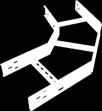
118 HOW TO ORDER
CABLE LADDERS CATALOGUE
 CABLE LADDERS CATALOGUE CONTENT INTRODUCTION 5 TECHNICAL INFORMATION 13 CABLE LADDER TRAY OVERVIEW 47 ALUMINUM LADDERS 57 STEEL LADDERS 65 LADDER FITTINGS 83 LADDER TYPE ACCESSORIES 89 FIXING ACCESSORIES
CABLE LADDER TRAY CATALOGUE.
 CABLE LADDER TRAY CATALOGUE www.ikkgroup.com INDEX Cable Ladder Tray Catalogue - About SFSP - Cable Ladder Trays - Cable Ladder Tray Runs - Cable Ladder Tray Fittings - Cable Tray Accessories - Cable Tray
CABLE LAddEr TrAY CATALoguE 1
 CABLE ladder TRAY catalogue www.ikkgroup.com 1 INDEX Cable Ladder Tray Catalogue - About SFSP - Cable Ladder Trays - Cable Ladder Tray Runs - Cable Ladder Tray Fittings - Cable Tray Accessories - Cable
Cable ladder systems. Development and testing
 Cable ladder systems Metsec cable ladder systems have been developed to provide cost effective solutions for the support of cables in a wide range of market sectors. These sectors include: * Coercial *
Series 2, 3, 4 Steel Cable Ladder Steel Cable Ladder, Series 2, 3, 4 & 5
 Cable Ladder with Slotted Rung (shown with alternating slot orientation) Cable Ladder with Slotted Rung (shown with continuous slot down - also available with continuous slot up) HDS-1 Steel Cable Ladder,
Series 1 Steel - Straight Sections
 Series 1 Steel - Straight Sections Series 1 Steel H-1 B-Line series Cable Tray Systems Series 1 Steel - ccessories & Fittings Series 1 Steel How The Service dvisor Works We know that your time is important!
CABLE MANAGEMENT SOLUTIONS CATALOGUE2003/04 A COMPLETE CABLE MANAGEMENT SOLUTION FOR COMMERCIAL AND INDUSTRIAL APPLICATIONS.
 CLE MNGEMENT SOLUTIONS CTLOGUE2003/04 COMPLETE CLE MNGEMENT SOLUTION FOR COMMERCIL ND INDUSTRIL PPLICTIONS www.legrand.co.uk FSTRCK F31 FSTRCK F31 SYSTEM STEEL WIRE CLE TRY Legrand With a large range of
Guidelines for Modernizing Existing Electrical Switchgear in LV and MV Networks
 Guidelines for Modernizing Existing Electrical Switchgear in LV and MV Networks by Georges Barbarin Executive summary Aging electrical switchgear infrastructure is a threat to the reliability of power
EZTray. Cable Management Made Easy
 EZTray Cable Management Made Easy PRESENTATION Introduction:.................................. 3 EZ Tray: The Tray That Saves You Time!.............. 4-5 EZ Tray: The Innovative Cable Management Solution....
Series 2, 3, 4, & 5 Aluminum - Straight Sections
 - Straight Sections I-1 B-Line series Cable Tray Systems - Accessories For Aluminum Fittings see fittings section pages L-1 thru L-17 How The Service Advisor Works We know that your time is important!
PRODUCT CATALOGUE - CABLE TRAYS
 PRODUCT CATALOGUE - CABLE TRAYS 098711969 shivshaktiindustries.delhi@gmail.com S. S. Engineering, B-2621, DSIDC Complex, Narela Industrial Area, New Narela, Delhi-140 Table of Contents Perforated Cable
PRODUCT CATALOGUE MECHANICALSUPPORT.CO.NZ 0508 CABLE TRAY CERTIFIED QUALITY SYSTEM ISO 9001:2015 REGISTERED COMPANY
 BS OHSAS 18001:2007 & AS/NZS 4801:2001 Certificate No. NZP1023HS R PRODUCT CATALOGUE REGISTERED COMPANY MECHANICALSUPPORT.CO.NZ 0508 CABLE TRAY Who we are Founded in 2005 by Directors Hayden Froggatt and
Power and Distribution Transformers
 Power and Distribution Transformers VRT Power Ltd. We Enable Energy VRT is a modern manufacturer for high-performance oil-immersed power transformers up to 800 MVA 500 kv. Customized design and the development
Singular and rows of racks in steel and stainless steel, PC racks. Server and distribution rack systems, enclosures and housings
 IT-SOLUTIONS Well conceived Haewa Group has gained a strong profile as an innovative and competent supplier for the machinery, systems, electrical and electronic industries, well beyond European geographic
Swifts SW strength, speed and flexibility
 Swifts SW strength, speed and flexibility STEEL WIRE CABLE TRAY / PRODUCT GUIDE Global vision... 21st Century solutions Established in the UK since 1972, Legrand is a world leading manufacturer of products
# INDEX. Created on: Revised on: N/A Cable Trays Manual 1 ABBREVIATIONS 2 SYSTEM COMPONENTS 3 DEFNITIONS 4 MATERIAL & FINISH OPTIONS
 # INDEX 1 ABBREVIATIONS 2 SYSTEM COMPONENTS 3 DEFNITIONS 4 MATERIAL & FINISH OPTIONS 5 GENERAL INFORMATION 6 ADAPTATION TO NEMA STANDARDS 7 CABLE TRAYS 8 CABLE LADDERS 9 ACCESSORIES 10 SUPPORTS 11 INSTALLATION
2507 (IBC 2006 ONLY) 3054 (IBC 2006 ONLY) Supreme Framing System Product Catalog
 3054 (IBC 2006 ONLY) Supreme Framing System Product Catalog") 12 0 2 / 2009IANT C B I PL COM 2507 (IBC 2006 ONLY) 3054 (IBC 2006 ONLY) R Supreme Framing System Product Catalog Supreme Framing System The Benefits of Supreme Framing System Speak for Themselves What
12 0 2 / 2009IANT C B I PL COM 2507 (IBC 2006 ONLY) 3054 (IBC 2006 ONLY) R Supreme Framing System Product Catalog Supreme Framing System The Benefits of Supreme Framing System Speak for Themselves What
Swifts SW. strength, speed and flexibility STEEL WIRE CABLE TRAY / PRODUCT GUIDE
 Swifts S strength, speed and flexibility STEEL IRE CABLE TRAY / PRODUCT GUIDE Global vision... 2st Century solutions Established in the UK since 972, Legrand is a world leading manufacturer of products
Midwest Dry Type Transformers
 Midwest Electric Products Midwest Dry Type Transformers Reliable and Efficient Performance From a Name You Know DOE 2016 Efficiency Transformers Catalog General Information...2 General Purpose... 3 Single-Phase
Cable Support Systems Admiralty Pattern Tray Cable Ladder Type 2/30 Cable Ladder Type 3/50 K-1000 Channel KT3/KT5 Ladder Tray
 www.hesales.com.au Cable Support Systems Admiralty Pattern Tray Cable Ladder Type 2/3 Cable Ladder Type 3/5 K- Channel KT3/KT5 Ladder Tray -.55mm base Galvabond - 2.4m length. 14mm side - Self-splicing
ABN Quality Endorsed Company ISO9001 Lic No EDITION 2
 ABN 43 8 71 335 SECTION 4 Cable Ladder and A U S T R A L I A W I D E A U S T R A L I A N M A D E Quality Endorsed Company ISO91 Lic No 13146 EDITION 2 SECTION 4: Cable Ladder & Type 3/5 Type 4/7L Type
Low Voltage Systems. MNS BS - front & rear access switchboards Tested, tried & trusted solutions. Power and productivity for a better world TM
 Low Voltage Systems MNS BS - front & rear access switchboards Tested, tried & trusted solutions Power and productivity for a better world TM MNS BS Tested, tried and trusted MNS - Global system design
CERTIFIED QUALITY SYSTEM ISO 9001:2015 REGISTERED COMPANY
 BS OHSAS 18001:2007 & AS/NZS 4801:2001 Certificate No. NZP1023HS R CABLE TRAY ALUMINIUM CABLE LADDER CABLE TRUNKING PRODUCT CATALOGUE Electrical Cable Containment REGISTERED COMPANY Mechanical Support
CONFIGURATION OF CABLE SUPPORT SYSTEMs
 CONFIGURATION OF CABLE s CABLE TRUNKING Page 4 - page 7 CABLE TRAY Page 8 - page 11 CABLE LADDER Page 12 - page 14 3 SS249/ IEC 61084 COMPLIED STEEL SURFACE CABLE TRUNKING CEE PRODUCT CODE SS-CEE 6 3 (#)
B kv T&D GAS INSULATED SWITCHGEAR
 GAS INSULATED SWITCHGEAR B 105 170 300 kv The increasing demand for electrical power in cities and industrial centers necessitates the installation of a compact and efficient distribution and transmission
Supreme. Supreme Framing System. Product Catalog IAPMO UNIFORM ER #0313
 Supreme Supreme Framing System Product Catalog IAPMO UNIFORM ER #0313 2507 Table of Contents Certification of Materials 5 LEED Credits 5 Independent Product Certification 5 Code Approvals, Performance
Insulating cable tray
 Cable conduction and protection system 66 raw material colour U23X Gris UV 66 U23X For support, protection and conduction of cables Good performance outdoors and to corrosion due to over 40 years experience
Busway Construction. Bus Bars
 Busway Construction Bus Bars A better understanding of what busway is can be gained by examining its construction. A typical Siemens Sentron busway section has three or four formed aluminum or copper bars
Welded cable ladder system
 Welded cable ladder system System information Pure OBO cable ladder competence Electricians have placed their trust in OBO Bettermann cable ladders for decades. The range stretches from riveted connections,
TEKNISK RIKTLINJE TR05-10E
 Notes Change notes Date 1 (A) Revision of standards and new template 09 / 07 2010 2 Template changed.clause. 10.5.1.4 support clamp inserted. Clause 10.5.4.2 creepage text revised. Clause 10.6.7 Dry inserted
ROOFING SOLUTIONS DESIGN GUIDE PURLINS AND GIRTS DESIGN GUIDE PURLINS AND GIRTS S&T029N
 DESIGN GUIDE PURLINS AND GIRTS ROOFING SOLUTIONS DESIGN GUIDE PURLINS AND GIRTS S&T029N JUL 2015 CONTENTS INTRODUCTION 2 Acknowledgements 2 Disclaimer 2 Product Technical Statement 3 Producer Statement
Series 2, 3, 4, & 5 Steel - Accessories
 - ccessories Splice Plates Standard 8-hole pattern for all steel splice plates. One pair including hardware provided with straight section. Boxed in pairs Expansion Splice Plates Expansion plates allow
Knürr Smaract. Knürr Smaract. CompactRack
 CompactRack Features Ample space for components and cabling provided in an efficient, compact design. The innovative frame concept with triangular extrusions ensures low weight while maintaining high stability.
WORK STATION BRIDGE CRANES
 FREE STANDING WORK STATION BRIDGE CRANES CAPACITIES: SPANS: ENCLOSED TRACKS: PRODUCTIVITY: Up to 4000 lbs Up to 30' Steel, Aluminum & Stainless Steel Average 28% Increase A Class Above... In Productivity.
IBC 2009/2012 COMPLIANT. Supreme Framing System. Product Catalog
 IBC 2009/2012 COMPLIANT 2507 Supreme Framing System Product Catalog Supreme Framing System The Benefits of Supreme Framing System Speak for Themselves What is the Supreme Framing System? Supreme Framing
SECTION LOW VOLTAGE DISTRIBUTION EQUIPMENT
 SECTION 16400 LOW VOLTAGE DISTRIBUTION EQUIPMENT A. General 1. The University does not accept Series-Rated equipment for power distribution switchboards, distribution panels and branch circuit panelboards.
Bridge Overhang Brackets
 Bridge C49, C49D, C49S and C49JR Bridge Dayton Superior offers the bridge contractor four different Horizontal Length versions of the C49 Bridge Bracket, which allows for maximum adjustability to meet
Steel Conduits Conduit Fittings Flexible Conduits
 Conduits Conduit Fittings Flexible Conduits CONTENT 1. INTRODUCTION VOLTECX products introduction and selecting VOLTECX 2. STEEL CONDUITS VOLTECX BS4568: Part 1: 1970 (Class 4) Conduit IEC 61386-21:2004;
SECTION PIPE HANGERS AND SUPPORTS
 Part I - GENERAL 1.01 SECTION INCLUDES A. The work covered under this section consists of the furnishing of all necessary labor, supervision, materials, equipment, and services to completely execute the
T&B Cable Tray. In this section...
 In this section... T& Cable Tray T& Cable Tray Overview... -260-261 luminum Tray... -262-309 Steel Tray... -310-333 One-Piece Tray... -334-357 Channel Tray... -358-373 Common ccessories... -374-376 Grounding
600 SERIES STANDARD DUTY STRAIGHT TRACK INSTALLATION INSTRUCTIONS
 600 SERIES STANDARD DUTY STRAIGHT TRACK INSTALLATION INSTRUCTIONS PLEASE READ INSTRUCTIONS THOROUGHLY BEFORE BEGINNING. A. BI-PARTING TRAVEL 1. Before raising track into position, determine location of
American made. American strong. The mark of a true craftsman. A strong history. Mission. . Republic Steel acquires facility from Elyria Iron and Steel
 American made. American strong. For more than 85 years, Republic Conduit has manufactured the nation s premier steel electrical conduit. The mark of a true craftsman. Since 1928, Republic Conduit has been
Infrastructure & Power. FP M c Cann. Tel: +44(0) Fax: +44(0)
 Fax: +44(0)") Infrastructure & Power FP M c Cann Tel: +44(0)1455 290 780 Fax: +44(0)1455 292 189 Infrastructure & Power Infrastructure & Power Power Infrastructure Cable Trough Systems FP McCann offers a specialist
Infrastructure & Power FP M c Cann Tel: +44(0)1455 290 780 Fax: +44(0)1455 292 189 Infrastructure & Power Infrastructure & Power Power Infrastructure Cable Trough Systems FP McCann offers a specialist
Wire ø in. Cat. No. ETQ 2002SS *ETQ 2004SS *ETQ 2006SS
 Steel Basket Tray Deep U-Profile Fast connection system, low profile for confined spaces The deep U-profile is ideally suited for light- to medium-duty commercial and industrial applications where space
Series 2, 3, 4, & 5 Aluminum - Accessories
 Wedge Lock Splice Plates Standard 4-hole pattern. Furnished in pairs, with hardware. One pair including hardware provided with each section. Boxed in pairs with hardware. For field installation drill 13
EQUIPMENT PROTECTION
 Contractor Specifier s Guide EQUIPMENT PROTECTION WWW.PENTAIRPROTECT.COM/HOFFMAN Volume 8 Hoffman Has You Covered From utility junctions to protecting relays, contactors and wire, Hoffman has you covered.
Cable Tray CT2D-18. Tray2Day SM. cable tray service program
 Cable Tray CT2D-18 Tray2Day SM cable tray service program * * At, we believe that power is a fundamental part of just about everything people do. That s why we re dedicated to helping our customers s find
WIRE BASKET TRAY CANADIAN ELECTRICAL RACEWAYS INC.
 CANADIAN ELECTRICAL RACEWAYS INC. WIRE BASKET TRAY Made of heavy-gauge zinc plated wire mesh, CER basket tray is ideal for your commercial or industrial cable management project. A full range of cable
CHAPTER V RESIDENTIAL WIRING
 CHAPTER V RESIDENTIAL WIRING 5.1. THE SERVICE ENTRANCE Buildings and other structures receive the electrical energy through the service entrance. In residential wiring, the electric company supply this
Microlectric Meter Sockets. Smart solutions that save you time and money
 Microlectric Meter Sockets Smart solutions that save you time and money 5 reasons why Microlectric is the only brand you need in meter sockets Save time and money with problem-free installation. Robust
ORDERING: Specify size, figure number, description, nominal pipe size or special O.D. and C-to-C dimension. C - C LOAD lb.
 Fig. 2110 www.pipingtech.com/fig2110 Sway Strut with 4 of Adjustment Engineered spring supports option 1 option 2 ORDERING: Specify size, figure number, description, nominal pipe size or special O.D. and
Volume 1 Series 2200 Specification for Road Works. Clause Title Page
 PARAPETS Contents Clause Title Page 2201 General... 2 2202 Vehicle... 2 2203 Anchorages and Attachment Systems for Vehicle... 2 2204 Amendments and Additions to BS 6779... 3 2205 Protection Against Corrosion...
Product Catalogue. Cable Management Solutions
 Product Catalogue Cable Management Solutions Cable management solutions Introduction Cable ladder & accessories Perforated tray & accessories Trunking & accessories Channel tray & accessories Superstrut
Series 2, 3, 4, & 5 Aluminum - Accessories
 The following is a list of accessories and fittings that can be provided with S8 tray. For more information on these items, contact our Engineering Department. Fittings Horizontal Bends 30 Bends with 24,
BUSWAY Low Voltage (Pow-R-Flex)
") BUSWAY LOW VOLTAGE (POW-R-FLEX) PART 1 GENERAL 1.01 1.02 SCOPE The Contractor shall furnish and install the busway system including all necessary fittings, hangers and accessories as specified herein and
BUSWAY LOW VOLTAGE (POW-R-FLEX) PART 1 GENERAL 1.01 1.02 SCOPE The Contractor shall furnish and install the busway system including all necessary fittings, hangers and accessories as specified herein and
Emergi-Lite EMEX central power supply solutions
 Emergi-Lite EMEX central power supply solutions Reliable central back up power Available for AC/AC and AC/DC power supply systems Exceptional overload performance Entire modular build for quick and simple
Design Standard. Purpose: Design Standard:
 Design Standard Purpose: This design standard has the purpose of creating a consistent application of motor-control centers throughout the East Side Union High School District, therefore achieving a standard
RE-PR1-F 1-Phase Din-Rail Mount 1.5, 3 & 6kW
 Page 1 of 5 RE-PR1-F 1-Phase Din-Rail Mount 1.5, 3 & Features: Benefits: 0-10Vdc or 0-5Vdc control input Over temperature protection with auto reset Din-rail mounting Efficient electronic switching No
SUBSTATION DESIGN TRAINING
 2017 SUBSTATION DESIGN TRAINING ADVANCE ELECTRICAL DESIGN & ENGINEERING INSITUTE (Registered under MSME& An ISO 9001:2008 CERTIFIED) Training Centre: Advance Group of Institutions C-1, Second Floor Near
Generator Fire Safety: Generator assemblies should be located outside the building.
 SECTION 33 70 00 - ELECTRICAL DISTRIBUTION PACKAGED GENERATOR ASSEMBLIES Generator Fire Safety: Generator assemblies should be located outside the building. All fuel piping from the outside of the building
 Siemens Com www.alfazalengineering.com Company Introduction Al-Fazal Engineering is Authorized Dealer of Siemens Components supply and Services also we are electrical construction material manufacturing
CABLE MANAGEMENT SOLUTIONS CATALOGUE2003/04 A COMPLETE CABLE MANAGEMENT SOLUTION FOR COMMERCIAL AND INDUSTRIAL APPLICATIONS.
 CABLE MANAGEMENT SOLUTIONS CATALOGUE03/04 A COMPLETE CABLE MANAGEMENT SOLUTION FOR COMMERCIAL AND INDUSTRIAL APPLICATIONS www.legrand.co.uk CHANNEL SUPPORT THE BACKBONE OF ALL YOUR SUPPORT NEEDS Swifts
CP-250E-60/72-208/240-MC4 Microinverter with Modular Trunk Cable
 CP-250E-60/72-208/240-MC4 Microinverter with Modular Trunk Cable Chilicon Power Aug 2016 1 CONTENTS CP-250E Microinverter System... 3 The CP-100 Cortex Gateway... 3 Important Safety Information... 4 Inverter
ADDER SYSTEM CABLE L
 17 Introduction CALE LADDE The ICMS cable ladder system consists of a wide range of aluminum and Steel cable ladders, Fittings and accessories. Ladder Trays are available in two models: Tubular rungs mechanically
Low Voltage Main Distribution Board
 s M series... Low Voltage Main Distribution Board Safe and intelligent power distribution Whether in industrial plants, in infrastructure or in buildings, all technical plant depends on the reliable supply
Commissioning chilled water TES systems
 Commissioning chilled water TES systems Chilled water thermal energy storage systems should be as simple as possible. The success of a project depends on documenting and continually evaluating the owner
Exceeding the standards with MNS
 Exceeding the standards with MNS Exceeding the standards with MNS 5 essentials of switchgear solutions Since ABB first introduced MNS the modular low voltage switchgear platform over forty years ago, MNS
Section COMMUNICATION EQUIPMENT ROOM FITTINGS. Section Communications Cabinets, Racks, Frames and Enclosures
 PART 1 GENERAL 1.1 WORK INCLUDED Section 27 11 00 COMMUNICATION EQUIPMENT ROOM FITTINGS Section 27 11 16 Communications Cabinets, Racks, Frames and Enclosures A. Provide all labor, materials, and equipment
Pretest Module 29 High Voltage Unit 1
 Pretest Module 29 High Voltage Unit 1 1. Is a person qualified to work on high-voltage installations when this module is completed? 2. What is the code definition of high-voltage? 3. What is the IEEE definition
Channel Cable Tray - Accessories & Fittings
 hannel able Tray - Straight Sections E-1 -Line series able Tray Systems hannel able Tray - ccessories & Fittings How The Service dvisor Works We know that your time is important! That s why the color-coding
EMC Compatible enclosure assembly
 EMC Compatible enclosure assembly 1 The definition of electromagnetic compatibility (EMC) is the ability of an electrical device to function satisfactorily in its electromagnetic environment without adversely
CAST RESIN DISTRIBUTION TRANSFORMERS 2016 EDITION
 CAST RESIN DISTRIBUTION TRANSFORMERS 2016 EDITION TMC TRANSFORMERS - GLOBAL NETWORK UK & IRELAND SPAIN NORTH AMERICA & CANADA GERMANY SWITZERLAND BENELUX & AUSTRIA ITALY POLAND INDIA CENTRAL & SOUTH AMERICA
Selection Guide Motor Control Device Solutions
 Selection Guide Motor Control Device Solutions Expect more and get it from c3controls. Our portfolio of Motor Control Devices consists of worldclass products designed and manufactured to meet your requirements
Multideck 50-V2 Features and Applications
 Features and Applications is a dovetail profile deck with a depth of 50mm providing spans up to 4m unpropped. Greater Design Efficiency The larger range of Multideck gauge thicknesses available allow much
CATALOGUE MEDIUM TO HEAVY DUTY IDLER
 CATALOGUE MEDIUM TO HEAVY DUTY IDLER Sandvik Materials Handling PULLEYS, IDLERS AND MATERIALS HANDLING SYSTEMS INDEX 3 ROLL INLINE CARRY & IMPACT PAGE 3 3 ROLL INLINE PLAIN P/A TRAINER PAGE 5 SINGLE ROLL
Tecstrut Channel Suspension & Framing System
 lindab I the ventilation products specialist Tecstrut Channel Suspension & Framing System Complies with HVCA specification DW144. Manufactured from corrosion resistant materials. Channels produced in accordance
VIBRATING WIRE SURFACE STRAIN GAUGE. Model SM-5B. Roctest Limited, All rights reserved.
 INSTRUCTION MANUAL VIBRATING WIRE SURFACE STRAIN GAUGE Model Roctest Limited, 2012. All rights reserved. This product should be installed and operated only by qualified personnel. Its misuse is potentially
Industrial Control Transformers
 6 Industrial Control Transformers Section 6 Industrial Control Transformers provide a low and safe control voltage for the operation of electromagnetic devices, such as motor starters, contactors, solenoids
SECTION HVAC POWER VENTILATORS
 SECTION 233423 HVAC POWER VENTILATORS 1. PART 1 GENERAL 1.1. RELATED DOCUMENTS A. Drawings and general provisions of the Contract, including General and Supplementary Conditions and Division 01 Specification
accqpulse Velocity Profiler Sensor Installation Guide
 accqpulse Velocity Profiler Sensor Installation Guide Instruction Sheet #69-7403-012 Released May 2016 Overview This instruction guide is for the installation of the accqpulse shallow water and deep water
Multideck 80-V2 Features and Applications
 Features and Applications is designed to incorporate all the advantages of the Multideck 60-V2 but in a deeper profile to provide longer spans up to 5.4m unpropped. Concrete Volume Savings Due to its unique
31-SDMS-02 REV. 01 SPECIFICATIONS FOR
 31-SDMS-02 REV. 01 SPECIFICATIONS FOR LOW VOLTAGE DISTRIBUTION PILLAR This specification is property of SEC and subject to change or modification without any notice C O N T E N T S S. NO. D E S C R I P
Clipper Defined. Shelving. Clipper Hi-Performance Shelving Systems. Growth with. Penco Hi-Performance Shelves. Growth with
 Defined Clipper Hi-Performance Systems At the heart of the Clipper System is the ingenious Penco Clipper Clip. It is easily installed, holds the shelf firmly in place, can be repositioned at any time,
Drawer runners for wooden drawers: FR roller runners
 : FR roller runners www.hettich.com Summary of ranges FR roller runners 3 Technik für Möbel 1 FR roller runners Noticeable convenience opening and closing drawers: roller runners with integrated self closing
High-Voltage Circuit-Breakers 3AP1/ kv up to 550 kv. Power Transmission and Distribution
 High-Voltage Circuit-Breakers AP/ 7.5 kv up to 550 kv Power Transmission and Distribution The AP/ High-Voltage Circuit-Breakers Now Applicable for 550 kv Decades of our experience in high-voltage switching
PIPINGSOLUTIONS, INC.
 Piping Stress Analysis Where do I start? The following information will take you step-by-step through the logic of the data collection effort that should occur prior to beginning to model a piping system
Personalized Solutions. Personalized Service.
 Personalized Solutions. Personalized Service. HOUSTON S SOLID WASTE Houston s Largest Privately Owned Waste Company MANAGEMENT HAS BEEN AN INTEGRAL PART OF SPRINT S OPERATIONS FOR OVER 25 YEARS. THE KNOWLEDGE,
Main switches in accordance with European standard directives
 Main switches in accordance with European standard directives N N ABB y ABB Switches in accordance with EU Directives New concept n order to dismantle technical barriers in commerce, the Council of the
Performa Mesh Trays. Flexible solution for the routing of cables
 Flexible solution for the routing of cables Solutions for each application Performa is one of the most flexible solutions on the market for the routing of cables in light duty and medium duty installations.
(RNW) Power Resistor Chamber. Token Electronics Industry Co., Ltd. Version: January 13, Web:
 Power Resistor Chamber. Token Electronics Industry Co., Ltd. Version: January 13, Web:") Version: January 13, 2017 (RNW) Power Resistor Chamber Token Electronics Industry Co., Ltd. Web: www.token.com.tw Email: rfq@token.com.tw Taiwan: No.137, Sec. 1, Zhongxing Rd., Wugu District, New Taipei
Version: January 13, 2017 (RNW) Power Resistor Chamber Token Electronics Industry Co., Ltd. Web: www.token.com.tw Email: rfq@token.com.tw Taiwan: No.137, Sec. 1, Zhongxing Rd., Wugu District, New Taipei
Low voltage capacitors CLMD Improving power factor and enhancing power quality of your network
 PRODUCT BROCHURE Low voltage capacitors CLMD Improving power factor and enhancing power quality of your network s.a. ABB n.v. Power Quality Products Allée Centrale 10 Z.I. Jumet B-6040 Charleroi (Jumet)
Sturdy hinge with added value. SlideOn
 Sturdy hinge with added value. SlideOn SlideOn easy to use, great performance SlideOn is extremely easy to fit, simply sliding on in seconds flat. Combining SlideOn with Hettich Direkt mounting plates
SECTORFLEX CABLE CATALOGUE
 SECTORFLEX CABLE CATALOGUE SAVING SPACE AND TIME R & D + i SERVING OUR CUSTOMERS PRESENTATION One of the largest companies in the sector worldwide. General Cable is a leading company in the manufacture
Medium Voltage Standby non-paralleling Control GUIDE FORM SPECIFICATION
 Medium Voltage Standby non-paralleling Control 1. GENERAL GUIDE FORM SPECIFICATION A. The requirements of the contract, Division 1, and part 16 apply to work in this section. 1.01 SECTIONS INCLUDE A. Medium
Upward opening flap fitting. Flap stay. Lift Junior (P. 6) mm / mm min. 45 mm max. 2.5 kg
 mm / mm min. 45 mm max. 2.5 kg") 2 www.hettich.com Range summary / technical comparison Upward opening flap fitting Flap stay Flap stay Application width / height, inside carcase depth, weight Lift Junior (P. 6) 300-1000 mm / 200-500
2 www.hettich.com Range summary / technical comparison Upward opening flap fitting Flap stay Flap stay Application width / height, inside carcase depth, weight Lift Junior (P. 6) 300-1000 mm / 200-500
MGE TM Galaxy TM 7000 GFC
 MGE TM Galaxy TM 7000 GFC Grid Frequency Converter (GFC) for Shore Connection solution 500 kva Performance 3 Phase Power Protection with high adaptability to meet the unique requirements of Shore Connection
PRODUCT CATALOGUE LOUCON METAL LTD. 37 and 39 Grenfell Crescent, Nepean, ON K2G 0G3. Hours of Operation: Monday-Friday 8:00 AM 5:00 PM
 PRODUCT CATALOGUE 37 and 39 Grenfell Crescent, Nepean, ON K2G 0G3 Hours of Operation: Monday-Friday 8:00 AM 5:00 PM Phone: (613) 226-1102 Fax: (613) 226-6097 e-mail: info@louconmetal.com web: www.louconmetal.com
STRAIGHT PERFORATED TRAY
 STRAIGHT PERFORATED TRAY RETURNED EDGE TYPE RETURNED FLANGE TYPE NOTE: Other sizes are available upon request WIDTH (W) HEIGHT (H) 50 15 15 150 15 15 15 400 15 500 15 600 15 STRAIGHT CABLE TRAY STANDARD
Expanding Your Solutions. Steel Framing and Accessories. ICC ESR and 2015 IBC, IRC
 Expanding Your Solutions Steel Framing and Accessories ICC ESR-30 20 and 2015 IBC, IRC Effective 1/4/2017 Table of Contents Introduction to CEMCO... 1 Product Identification... 2 3 LEED Certification...
BOSS STEEL Metal Reference Book Version 9
 Intro BOSS STEEL Metal Reference Book Version 9 This ninth edition of the Boss Steel Metal Reference Book has been designed to inform and assist you in making the right decision when it comes to acquiring