Table of Contents S.No Title Page No 1 HIGHWAY PLANNING AND ALIGNMENT History of highway engineering Ancient Roads
|
|
|
- Logan Stewart
- 5 years ago
- Views:
Transcription
1 Table of Contents S.No Title Page No 1 HIGHWAY PLANNING AND ALIGNMENT History of highway engineering Ancient Roads Roman roads French roads British roads Bombay road congress Road development Plans Five Year Plans Classifications of roads Road patterns Camber Types of cambers Width of carriage way Importance of Kerbs Right of way Alignment 24 2 GEOMETRIC DESIGN OF HIGHWAYS Design Speed Topography Other factors Factors affecting Sight distance Stopping sight distance Overtaking sight distance Horizontal curve Analysis of Super-elevation Design of super-elevation Mechanical widening Psychological widening Length of transition curve Vertical alignment Types of gradient Creeper lane Grade compensation Summit curve Types of Summit Curve Design considerations for valley curve Length of the valley curve 36 3 DESIGN OF FLEXIBLE AND RIGID PAVEMENTS Flexible pavements 38
2 3.2 Types of Flexible Pavements Types of Failure in flexible pavements Rigid pavements Types of Rigid Pavements Material characterization for pavement construction The Environmental factors that affect the pavement materials Factors which affects pavement design Typical layers of a flexible pavement Important factor in the pavement design The construction of WBM Equivalent single wheel load Requirements of Bituminous mixes Design procedures for flexible pavement Equivalent single axle load Design criteria as per IRC Design procedure of IRC for flexible pavement 48 4 HIGHWAY CONSTRUCTION MATERIALS AND PRACTICE Soil Types Tests on soil Crushing test Abrasion test Impact test Soundness test Shape tests Specific Gravity and water absorption Bitumen adhesion test California Bearing Ratio Test Desirable properties of aggregates Different forms of bitumen Tests on bitumen Penetration test Specific gravity test and Viscosity test 64 5 EVALUATION AND MAINTENANCE OF PAVEMENTS Surface deformation in detail Surface defects in detail Patches And Potholes Edge Defects In Detail Causes And Remedies Of Shear Cracks 72
3 HIGHWAY ENGINEERING L T P C OBJECTIVES: To give an overview about the highway engineering with respect to, planning, design, construction and maintenance of highways as per IRC standards, specifications and methods. UNIT I HIGHWAY PLANNING AND ALIGNMENT 8 Significance of highway planning Modal limitations towards sustainability - History of road development in India Classification of highways Locations and functions Factors influencing highway alignment Soil suitability analysis - Road ecology - Engineering surveys for alignment, objectives, conventional and modern methods. UNIT II GEOMETRIC DESIGN OF HIGHWAYS 12 Typical cross sections of Urban and Rural roads Cross sectional elements - Sight distances Horizontal curves, Super elevation, transition curves, widening at curves Vertical curves - Gradients, Special consideration for hill roads - Hairpin bends Lateral and vertical clearance at underpasses. UNIT III DESIGN OF FLEXIBLE AND RIGID PAVEMENTS 9 Design principles pavement components and their role - Design practice for flexible and rigid Pavements (IRC methods only) - Embankments. UNIT IV HIGHWAY CONSTRUCTION MATERIALS AND PRACTICE 8 Highway construction materials, properties, testing methods CBR Test for subgrade - tests on aggregate & bitumen Construction practice including modern materials and methods,bituminous and Concrete road construction, Polymer modified bitumen, Recycling, Different materials Glass, Fiber, Plastic, Geo-Textiles, Geo-Membrane (problem not included) - Quality control measures - Highway drainage Construction machineries. UNIT V EVALUATION AND MAINTENANCE OF PAVEMENTS 8 Pavement distress in flexible and rigid pavements Pavement Management Systems - Pavement evaluation, roughness, present serviceability index, skid resistance, structural evaluation, evaluation by deflection measurements Strengthening of pavements Types of maintenance Highway Project formulation. OUTCOMES: TOTAL: 45 PERIODS The students completing this course would have acquired knowledge on planning, design, construction and maintenance of highways as per IRC standards and other methods. TEXT BOOKS: 1. Khanna.S. K., Justo.C.E.G and Veeraragavan A. "", Nemchand Publishers, Subramanian K.P., "Highways, Railways, Airport and Harbour Engineering", Scitech Publications (India), Chennai, Indian Road Congress (IRC), Guidelines and Special Publications of Planning and Design. REFERENCES: 1. Kadiyali.L.R. "Principles and Practice of ", Khanna Technical Publications, 8 th edition Delhi, Yang H. Huang, "Pavement Analysis and Design", Pearson Education Inc, Nineth Impression, South Asia, Ian D. Walsh, "ICE manual of highway design and management", ICE Publishers, I st Edition, USA, Fred L. Mannering, Scott S. Washburn and Walter P.Kilareski, "Principles of Highway Engineering and Traffic Analysis", Wiley India Pvt. Ltd., New Delhi, Garber and Hoel, "Principles of Traffic and ", CENGAGE Learning, New Delhi, O Flaherty.C.A "Highways, Butterworth Heinemann, Oxford, 2006

4 UNIT I HIGHWAY PLANNING AND ALIGNMENT Significance of highway planning Modal limitations towards sustainability History of road development in India Classification of highways Locations and functions Factors influencing highway alignment Soil suitability analysis - Road ecology - Engineering surveys for alignment, objectives, conventional and modern methods. 1.1 History of highway engineering The history of highway enginnering gives us an idea about the roads of ancient times. Roads in Rome were constructed in a large scale and it radiated in many directions helping them in military operations. Thus they are considered to be pioneers in road construction. In this section we will see in detail about Ancient roads, Roman roads, British roads, French roads etc Ancient Roads The first mode of transport was by foot. These human pathways would have been developed for specific purposes leading to camp sites, food, streams for drinking water etc. The next major mode of transport was the use of animals for transporting both men and materials. Since these loaded animals required more horizontal and vertical clearances than the walking man, track ways emerged. The invention of wheel in Mesopotamian civilization led to the development of animal drawn vehicles. Then it became necessary that the road surface should be capable of carrying greater loads. Thus roads with harder surfaces emerged. To provide adequate strength to carry the wheels, the new ways tended to follow the sunny drier side of a path. These have led to the development of foot-paths. After the invention of wheel, animal drawn vehicles were developed and the need for hard surface road emerged. Traces of such hard roads were obtained from various ancient civilization dated as old as 3500 BC. The earliest authentic record of road was found from Assyrian empire constructed about 1900 BC Roman roads The earliest large scale road construction is attributed to Romans who constructed an extensive system of roads radiating in many directions from Rome. They were a remarkable achievement and provided travel times across Europe, Asia minor, and north Africa. Romans recognized that the fundamentals of good road construction were to provide good drainage, good material and good workmanship. Their roads were very durable, and some are still existing. Roman roads were always constructed on a firm 1

5 formed subgrade strengthened where necessary with wooden piles. The roads were bordered on both sides by longitudinal drains. The next step was the construction of the agger. This was a raised formation up to a 1 meter high and 15 m wide and was constructed with materials excavated during the side drain construction. This was then topped with a sand leveling course. The agger contributed greatly to moisture control in the pavement. The pavement structure on the top of the agger varied greatly. In the case of heavy traffic, a surface course of large 250 mm thick hexagonal flag stones were provided. A typical cross section of roman road The main features of the Roman roads are that they were built straight regardless of gradient and used heavy foundation stones at the bottom. They mixed lime and volcanic puzzolana to make mortar and they added gravel to this mortar to make concrete. Thus concrete was a major Roman road making innovation French roads The next major development in the road construction occurred during the regime of Napoleon. The significant contributions were given by Tresaguet in 1764 and a typical cross section of this road. He developed a cheaper method of construction than the lavish and locally unsuccessful revival of Roman practice. The pavement used 200 mm pieces of quarried stone of a more compact form and shaped such that they had at least one flat side which was placed on a compact formation. Smaller pieces of broken stones were then compacted into the spaces between larger stones to provide a level surface. Finally the running layer was made with a layer of 25 mm sized broken stone. All this structure was placed in a trench in order to keep the running surface level with the surrounding country side. This created major drainage problems which were counteracted by making the surface as impervious as possible, cambering the surface and providing deep side ditches. He gave much importance for drainage. He also enunciated the necessity for continuous organized maintenance, instead of intermittent repairs if the roads were to be kept usable all times. For this he divided the roads between villages into sections of such length that an entire road could be covered by maintenance men living nearby British roads The British government also gave importance to road construction. The British engineer John Macadam introduced what can be considered as the first scientific road construction method. Stone size was an important element of Macadam recipe. By empirical observation of many roads 2

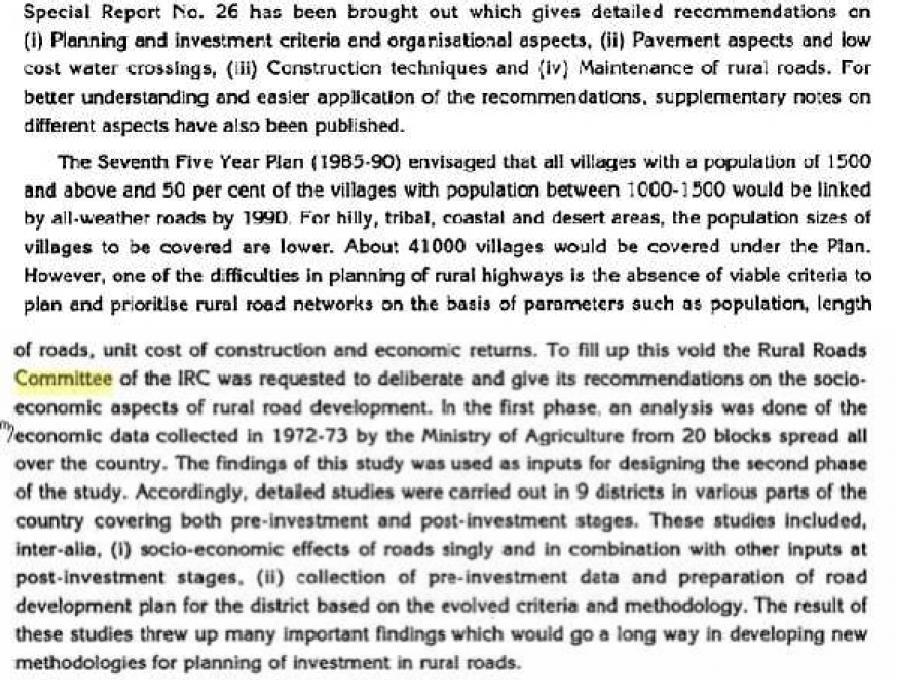
6 , he came to realize that 250 mm layers of well compacted broken angular stone would provide the same strength and stiffness and a better running surface than an expensive pavement founded on large stone blocks. Thus he introduced an economical method of road construction. The mechanical interlock between the individual stone pieces provided strength and stiffness to the course. But the inter particle friction abraded the sharp interlocking faces and partly destroy the effectiveness of the course. This effect was overcome by introducing good quality interstitial finer material to produce a well-graded mix. Such mixes also proved less permeable and easier to compact. 1.2 Bombay road congress: The length of roads envisaged under the Nagpur plan was achieved by the end of it, but the road system was deficient in many respects. The changed economic, industrial and agricultural conditions in the country warranted a review of the Nagpur plan. Accordingly a 20-year plan was drafted by the Roads wing of Government of India, which is popularly known as the Bombay plan. The highlights of the plan were: It was the second 20 year road plan ( ) The total road length targeted to construct was about 10 lakhs. Rural roads were given specific attention. Scientific methods of construction was proposed for the rural roads. The necessary technical advice to the Panchayaths should be given by State PWD's. They suggested that the length of the road should be increased so as to give a road density of 32kms/100 sq.km The construction of 1600 km of expressways was also then included in the plan. 3


7 4
8 1.3 Road development Plans. 5

9 6

10 1.4 Five Year Plans 7
11 8
12 9

13 10

14 11
15 12


16 13


17 14
18 15
19 1.5 Classifications of roads 16
20 17


21 1.6 Road patterns 18
22 19

23 1.7 Camber Camber or cant is the cross slope provided to raise middle of the road surface in the transverse direction to drain of rain water from road surface. The objectives of providing camber are: _ Surface protection especially for gravel and bituminous roads _ Sub-grade protection by proper drainage _ Quick drying of pavement which in turn increases safety Too steep slope is undesirable for it will erode the surface. Camber is measured in 1 in n or n% (Eg. 1 in 50 or 2%) and the value depends on the type of pavement surface. The values suggested by IRC for various categories of pavement is given in Table. 20


24 1.7.1 Types of cambers. The common types of camber are parabolic, straight, or combination of them 1.8 Width of carriage way Width of the carriage way or the width of the pavement depends on the width of the traffic lane and number of lanes. Width of a traffic lane depends on the width of the vehicle and the clearance. Side clearance improves operating speed and safety. The maximum permissible width of a vehicle is 2.44 and the desirable side clearance for single lane traffic is 0.68 m. This require minimum of lane width of 3.75 m for a single lane road.however, the side clearance required is about 0.53 m, on either side and 1.06 m in the center. Therefore, a two lane road require minimum of 3.5 meter for each lane The desirable carriage way width recommended by IRC is given in Table 21
25 1.9 Importance of Kerbs Kerbs indicate the boundary between the carriage way and the shoulder or islands or footpaths. Different types of kerbs are Low or mountable kerbs : This type of kerbs are provided such that they encourage the traffic to remain in the through traffic lanes and also allow the driver to enter the shoulder area with little difficulty. The height of this kerb is about 10 cm above the pavement edge with a slope which allows the vehicle to climb easily. This is usually provided at medians and channelization schemes and also helps in longitudinal drainage. Semi-barrier type kerbs : When the pedestrian traffic is high, these kerbs are provided. Their height is 15 cm above the pavement edge. This type of kerb prevents encroachment of parking vehicles, but at acute emergency it is possible to drive over this kerb with some difficulty. Barrier type kerbs : They are designed to discourage vehicles from leaving the pavement. They are provided when there is considerable amount of pedestrian traffic. They are placed at a height of 20 cm above the pavement edge with a steep batter. Submerged kerbs: They are used in rural roads. The kerbs are provided at pavement edges between the pavement edge and shoulders. They provide lateral confinement and stability to the pavement. Width of formation: Width of formation or roadway width is the sum of the widths of pavements or carriage way including separators and shoulders. 22

26 1.10 Right of way. Right of way (ROW) or land width is the width of land acquired for the road, along its alignment. It should be adequate to accommodate all the cross-sectional elements of the highway and may reasonably provide for future development. To prevent ribbon development along highways, control lines and building lines may be provided. Control line is a line which represents the nearest limits of future uncontrolled building activity in relation to a road. Building line represents a line on either side of the road, between which and the road no building activity is permitted at all. The right of way width is governed by: Width of formation: It depends on the category of the highway and width of roadway and road margins. Height of embankment or depth of cutting: It is governed by the topography and the vertical alignment. Side slopes of embankment or cutting: It depends on the height of the slope, soil type etc. Drainage system and their size which depends on rainfall, topography etc. Sight distance considerations : On curves etc. there is restriction to the visibility on the inner side of the curve due to the presence of some obstructions like building structures etc. 23
27 Reserve land for future widening: Some land has to be acquired in advance anticipating future developments like widening of the road. The importance of reserved land is emphasized by the following. Extra width of land is available for the construction of roadside facilities. Land acquisition is not possible later, because the land may be occupied for various other purposes (buildings, business etc.) The normal ROW requirements for built up and open areas as specified by IRC is given in Table 12:4 A typical cross section of a ROW is given in Figure 12: Alignment The position or the layout of the central line of the highway on the ground is called the alignment. Horizontal alignment includes straight and curved paths. Vertical alignment includes level and gradients. Alignment decision is important because a bad alignment will enhance the construction, maintenance and vehicle operating costs. Once an alignment is fixed and constructed, it is not easy to change it due to increase in cost of adjoining land and construction of costly structures by the roadside. 24
28 Requirements The requirements of an ideal alignment are The alignment between two terminal stations should be short and as far as possible be straight, but due to some practical considerations deviations may be needed. The alignment should be easy to construct and maintain. It should be easy for the operation of vehicles. So to the maximum extend easy gradients and curves should be provided. It should be safe both from the construction and operating point of view especially at slopes, embankments, and cutting. It should have safe geometric features. The alignment should be economical and it can be considered so only when the initial cost, maintenance cost, and operating cost are minimum. Factors controlling alignment We have seen the requirements of an alignment. But it is not always possible to satisfy all these requirements. Hence we have to make a judicial choice considering all the factors. The various factors that control the alignment are as follows: 1.Obligatory points: These are the control points governing the highway alignment. These points are classified into two categories. Points through which it should pass and points through which it should not pass. Some of the examples are: o Bridge site: The bridge can be located only where the river has straight and permanent path and also where the abutment and pier can be strongly founded. The road approach to the bridge should not be curved and skew crossing should be avoided as possible. Thus to locate a bridge the highway alignment may be changed. o Mountain: While the alignment passes through a mountain, the various alternatives are to either construct a tunnel or to go round the hills. The suitability of the alternative depends on factors like topography, site conditions and construction and operation cost. o Intermediate town: The alignment may be slightly deviated to connect an intermediate town or village nearby. These were some of the obligatory points through which the alignment should pass. Coming to the second category, that is the points through which the alignment should not pass are: Religious places: These have been protected by the law from being acquired for any purpose. Therefore, these points should be avoided while aligning. Very costly structures: Acquiring such structures means heavy compensation which would result in an increase in initial cost. So the alignment may be deviated not to pass through that point. Lakes/ponds etc: The presence of a lake or pond on the alignment path would also necessitate deviation of the alignment. 2. Traffic: The alignment should suit the traffic requirements. Based on the origin- destination data 25
29 of the area, the desire lines should be drawn. The new alignment should be drawn keeping in view the desire lines, traffic flow pattern etc. 3. Geometric design: Geometric design factors such as gradient, radius of curve, sight distance etc. also govern the alignment of the highway. To keep the radius of curve minimum, it may be required to change the alignment. The alignments should be finalized such that the obstructions to visibility do not restrict the minimum requirements of sight distance. The design standards vary with the class of road and the terrain and accordingly the highway should be aligned. 4. Economy: The alignment finalized should be economical. All the three costs i.e. construction, maintenance, and operating cost should be minimum. The construction cost can be decreased much if it is possible to maintain a balance between cutting and filling. Also try to avoid very high embankments and very deep cuttings as the construction cost will be very higher in these cases. 26
30 UNIT II GEOMETRIC DESIGN OF HIGHWAYS Typical cross sections of Urban and Rural roads Cross sectional elements - Sight distances Horizontal curves, Super elevation, transition curves, widening at curves Vertical curves Gradients, Special consideration for hill roads - Hairpin bends Lateral and vertical clearance at underpasses 2.1 Design Speed The design speed, as noted earlier, is the single most important factor in the design of horizontal alignment. The design speed also depends on the type of the road. For e.g, the design speed expected from a National highway will be much higher than a village road, and hence the curve geometry will vary significantly. The design speed also depends on the type of terrain. A plain terrain can afford to have any geometry, but for the same standard in a hilly terrain requires substantial cutting and filling implying exorbitant costs as well as safety concern due to unstable slopes. Therefore, the design speed is normally reduced for terrains with steep slopes. For instance, Indian Road Congress (IRC) has classified the terrains into four categories, namely plain, rolling, mountainous, and steep based on the cross slope as given in table. Based on the type of road and type of terrain the design speed varies. The IRC has suggested desirable or ruling speed as well as minimum suggested design speed and is tabulated in table. Table : Terrain classification Terrain classification Cross slope (%) Plain 0-10 Rolling Mountainous Steep The recommended design speed is given in Table. Table : Design speed in as per IRC (ruling and minimum) Type Plain Rolling Hilly Steep NS&SH MDR ODR VR
31 2.1.1 Topography: The next important factor that affects the geometric design is the topography. It is easier to construct roads with required standards for a plain terrain. However, for a given design speed, the construction cost increases multiform with the gradient and the terrain. Therefore, geometric design standards are different for different terrain to keep the cost of construction and time of construction under control. This is characterized by sharper curves and steeper gradients Other factors : In addition to design speed and topography, there are various other factors that affect the geometric design and they are brie y discussed below: Vehicle: The dimensions, weight of the axle and operating characteristics of a vehicle influence the design aspects such as width of the pavement, radii of the curve, clearances, parking geometrics etc. A design vehicle which has standard weight, dimensions and operating characteristics are used to establish highway design controls to accommodate vehicles of a designated type. Human: The important human factors that influence geometric design are the physical, mental and psychological characteristics of the driver and pedestrians like the reaction time. Traffic: It will be uneconomical to design the road for peak traffic flow. Therefore a reasonable value of traffic volume is selected as the design hourly volume which is determined from the various traffic data collected. The geometric design is thus based on this design volume, capacity etc. Environmental: Factors like air pollution, noise pollution etc. should be given due consideration in the geometric design of roads. Economy: The design adopted should be economical as far as possible. It should match with the funds allotted for capital cost and maintenance cost. Others: Geometric design should affected. be such that the aesthetics of the region is not 2.2 Factors affecting Sight distance The most important consideration in all these is that at all times the driver traveling at the design speed of the highway must have sufficient carriageway distance within his line of vision to allow him to stop his vehicle before colliding with a slowly moving or stationary object appearing suddenly in his own traffic lane. The computation of sight distance depends on: Reaction time of the driver Reaction time of a driver is the time taken from the instant the object is visible to the driver to the instant when the brakes are applied. The total reaction time may be split up into four components based on PIEV theory. In practice, all these times are usually combined into a total perceptionreaction time suitable for design purposes as well as for easy measurement. Many of the studies show that drivers require about 1.5 to 2 secs under normal conditions. However, taking into 28
32 consideration the variability of driver characteristics, a higher value is normally used in design. For example, IRC suggests a reaction time of 2.5 secs. Speed of the vehicle The speed of the vehicle very much affects the sight distance. Higher the speed, more time will be required to stop the vehicle. Hence it is evident that, as the speed increases, sight distance also increases. Efficiency of brakes The efficiency of the brakes depends upon the age of the vehicle, vehicle characteristics etc. If the brake efficiency is 100%, the vehicle will stop the moment the brakes are applied. But practically, it is not possible to achieve 100% brake efficiency. Therefore the sight distance required will be more when the efficiency of brakes are less. Also for safe geometric design, we assume that the vehicles have only 50% brake efficiency. Frictional resistance between the tyre and the road The frictional resistance between the tyre and road plays an important role to bring the vehicle to stop. When the frictional resistance is more, the vehicles stop immediately. Thus sight required will be less. No separate provision for brake efficiency is provided while computing the sight distance. This is taken into account along with the factor of longitudinal friction. IRC has specified the value of longitudinal friction in between 0.35 to 0.4. Gradient of the road. Gradient of the road also affects the sight distance. While climbing up a gradient, the vehicle can stop immediately. Therefore sight distance required is less. While descending a gradient, gravity also comes into action and more time will be required to stop the vehicle. Sight distance required will be more in this case. 2.3 Stopping sight distance Stopping sight distance (SSD) is the minimum sight distance available on a highway at any spot having sufficient length to enable the driver to stop a vehicle traveling at design speed, safely without collision with any other obstruction. There is a term called safe stopping distance and is one of the important measures in tra c engineering. It is the distance a vehicle travels from the point at which a situation is rst perceived to the time the deceleration is complete. Drivers must have adequate time if they are to suddenly respond to a situation. Thus in highway design, sight distance atleast equal to the safe stopping distance should be provided. The stopping sight distance is the sum of lag distance and the braking distance. Lag distance is the distance the vehicle traveled during the reaction time t and is given by vt, where v is the velocity in m=sec2. Braking distance is the distance traveled by the vehicle during braking operation. For a level road this is obtained by equating the work done in stopping the vehicle and the kinetic energy of the vehicle. If F is the maximum frictional force developed and the braking distance is l, then work done against friction in stopping the vehicle is F l = f W l where W is the total weight of the vehicle. The kinetic energy at the design speed is Therefore, the SSD = lag distance + braking distance and given by: where v is the design speed in m=sec2, t is the reaction time in sec, g is the acceleration due to gravity and f is the coefficient of friction. The coefficient of friction f is given below for various design speed. When there is an ascending gradient of say +n%, the component of gravity adds to braking action and hence braking distance is decreased. The component of gravity acting parallel to the surface which adds to the braking force is equal to W sin W tan = W n=100. Equating kinetic energy and work done: 29
33 Similarly the braking distance can be derived for a descending gradient. 2.4 Overtaking sight distance The overtaking sight distance is the minimum distance open to the vision of the driver of a vehicle intending to overtake the slow vehicle ahead safely against the traffic in the opposite direction. The overtaking sight distance or passing sight distance is measured along the center line of the road over which a driver with his eye level 1.2 m above the road surface can see the top of an object 1.2 m above the road surface. The factors that affect the OSD are: 1. Velocities of the overtaking vehicle, overtaken vehicle and of the vehicle coming in the opposite direction. 2. Spacing between vehicles, which in-turn depends on the speed 3. Skill and reaction time of the driver. 4. Rate of acceleration of overtaking vehicle. 5. Gradient of the road. The dynamics of the overtaking operation is given in the figure which is a time-space diagram. The x-axis denotes the time and y-axis shows the distance traveled by the vehicles. The trajectory of the slow moving vehicle (B) is shown as a straight line which indicates that it is traveling at a constant speed. A fast moving vehicle (A) is traveling behind the vehicle B. The trajectory of the vehicle is shown initially with a steeper slope. The dotted line indicates the path of the vehicle A if B was absent. The vehicle A slows down to follow the vehicle B as shown in the figure with same slope from t0 to t1. Then it overtakes the vehicle B and occupies the left lane at time t 3. The time duration T = t3 t1 is the actual duration of the overtaking operation. The snapshots of the road at time t0 ; t1, and t3 are shown on the left side of the figure. From the Figure, the overtaking sight distance consists of three parts. It is assumed that the vehicle A is forced to reduce its speed to vb, the speed of the slow moving vehicle B and travels behind it during the reaction time t of the driver. So d1 is given by: d1 = vb t Then the vehicle A starts to accelerate, shifts the lane, overtake and shift back to the original lane. The vehicle A maintains the spacing s before and after overtaking. The spacing s in m is given by: s = 0:7vb + 6 Let T be the duration of actual overtaking. The distance traveled by B during the overtaking operation is 2s + vb T. Also, during this time, vehicle A accelerated from initial velocity vb and overtaking is completed while 30
34 The distance traveled by the vehicle C moving at design speed v m=sec during overtaking operation is given by: where vb is the velocity of the slow moving vehicle in m=sec2, t the reaction time of the driver in sec, s is the spacing between the two vehicle in m and a is the overtaking vehicles acceleration in m=sec2. In case the speed of the overtaken vehicle is not given, it can be assumed that it moves 16 kmph slower the design speed. The acceleration values of the fast vehicle depends on its speed 2.5 Horizontal curve The presence of horizontal curve imparts centrifugal force which is reactive force acting outward on a vehicle negotiating it. Centrifugal force depends on speed and radius of the horizontal curve and is counteracted to a certain extent by transverse friction between the tyre and pavement surface. On a curved road, this force tends to cause the vehicle to overrun or to slide outward from the centre of road curvature. For proper design of the curve, an understanding of the forces acting on a vehicle taking a horizontal curve is necessary. Various forces acting on the vehicle are illustrated in the figure. They are the centrifugal force (P) acting outward, weight of the vehicle (W) acting downward, and the reaction of the ground on the wheels (R A and RB ). The centrifugal force and the weight is assumed to be from the centre of gravity which is at h units above the ground. Let the wheel base be assumed as b units. The centrifugal force P in kg=m2 is given by where W is the weight of the vehicle in kg, v is the speed of the vehicle in m=sec, g is the acceleration due to gravity in m=sec2 and R is the radius of the curve in m. The centrifugal force has two effects: A tendency to overturn the vehicle about the outer wheels and a tendency for transverse skidding. Taking moments of the forces with respect to the outer wheel when the vehicle is just The second tendency of the vehicle is for transverse skidding. i.e. When the centrifugal force P is greater than the maximum possible transverse skid resistance due to friction between the pavement surface and tyre. The transverse skid resistance (F) is given by: F= = FA + FB f (RA + RB ) = fw where FA and FB is the fractional force at tyre A and B, R A and RB is the reaction at tyre A and B, f is the lateral coefficient of friction and W is the weight of the vehicle. This is counteracted by the centrifugal force (P), and equating: 31
35 2.6 Analysis of Super-elevation Super-elevation or cant or banking is the transverse slope provided at horizontal curve to counteract the centrifugal force, by raising the outer edge of the pavement with respect to the inner edge, throughout the length of the horizontal curve. When the outer edge is raised, a component of the curve weight will be complimented in counteracting the effect of centrifugal force. In order to find out how much this raising should be, the following analysis may be done. The forces acting on a vehicle while taking a horizontal curve with superelevation is shown in figure Forces acting on a vehicle on horizontal curve of radius R m at a speed of v m=sec2 are: Analysis of super-elevation P the centrifugal force acting horizontally out-wards through the center of gravity, W the weight of the vehicle acting down-wards through the center of gravity, and F the friction force between the wheels and the pavement, along the surface inward. At equilibrium, by resolving the forces parallel to the surface of the pavement we get, P cos = W sinθ + FA + FB = W sinθ + f (RA + RB) = W sinθ + f (W cosθ + P sinθ) where W is the weight of the vehicle, P is the centrifugal force, f is the coefficient of friction, is the transverse slope due to super elevation. Dividing by W cosθ, we get: By substituting the value of P/W this in equation Design of super-elevation While designing the various elements of the road like superelevation, we design it for a particular vehicle called design vehicle which has some standard weight and dimensions. But in the actual case, the road has to cater for mixed traffic. Different vehicles with different dimensions and varying speeds ply on the road. For example, in the case of a heavily loaded truck with high centre of gravity and low speed, superelevation should be less; otherwise chances of toppling are more. Taking into practical considerations of all such situations, IRC has given some guidelines about the maximum and minimum superelevation etc. For fast moving vehicles, providing higher superelevation without considering coefficient of friction is safe, i.e. centrifugal force is fully counteracted by the weight of the vehicle or superelevation. For slow moving vehicles, providing lower superelevation considering coefficient of friction is safe, i.e. centrifugal force is counteracted by superelevation and coefficient of friction. IRC suggests following 2.7 Mechanical widening The reasons for the mechanical widening are: When a vehicle negotiates a horizontal curve, the rear wheels follow a path of shorter radius than the front wheels as shown in figure. This phenomenon is called o - tracking, and has the effect of increasing the effective width of a road space required by the vehicle. Therefore, to provide the same clearance between vehicles traveling in opposite direction on curved roads as is provided on straight sections, there must be extra width of carriageway available. This is an important factor when high proportion of vehicles are using the road. Trailor trucks also need extra carriageway, depending on the type of joint. In addition speeds higher than the design speed causes transverse skidding which requires additional width for safety purpose. The expression for extra width can be derived from the simple geometry of 32
36 a vehicle at a horizontal curve as shown in figure. Let R1 is the radius of the outer track line of the rear wheel, R2 is the radius of the outer track line of the front wheel l is the distance between the front and rear wheel, n is the number of lanes, then the mechanical widening Wm is derived below: 2.8 Psychological widening `Widening of pavements has to be done for some psychological reasons also. There is a tendency for the drivers to drive close to the edges of the pavement on curves. Some extra space is to be provided for more clearance for the crossing and overtaking operations on curves. IRC proposed an empirical relation for the psychological Widening at horizontal curves Wps: 2.9 Length of transition curve The length of the transition curve should be determined as the maximum of the following three criteria: rate of change of centrifugal acceleration, rate of change of superelevation, and an empirical formula given by IRC. Rate of change of centrifugal acceleration At the tangent point, radius is infinity and hence centrifugal acceleration is zero. At the end of the transition, the radius R has minimum value R. The rate of change of centrifugal acceleration should be adopted such that the design should not cause discomfort to the drivers. If c is the rate of change of centrifugal acceleration, it is given by an empirical formula suggested by by IRC 2.10 Vertical alignment The vertical alignment of a road consists of gradients(straight lines in a vertical plane) and vertical curves. The vertical alignment is usually drawn as a pro le, which is a graph with elevation as vertical axis and the horizontal distance along the centre line of the road as the the horizontal axis. Just as a circular curve is used to connect horizontal straight stretches of road, vertical curves connect two gradients. When these two curves meet, they form either convex or concave. The former is called a summit curve, while the latter is called a valley curve Types of gradient Many studies have shown that gradient upto seven percent can have considerable effect on the speeds of the passenger cars. On the contrary, the speeds of the heavy vehicles are considerably reduced when long gradients as at as two percent is adopted. Although, flatter gradients are desirable, it is evident that the cost of construction will also be very high. Therefore, IRC has specified the desirable gradients for each terrain. However, it may not be economically viable to adopt such gradients in certain locations, steeper gradients are permitted for short duration. Different types of grades are discussed below and the recommended type of gradients for each type of terrain and type of gradient is given in table 17:1. Ruling gradient, limiting gradient, exceptional gradient and minimum gradient are some types of gradients which are discussed below. Ruling gradient The ruling gradient or the design gradient is the maximum gradient with which the designer attempts 33
37 to design the vertical pro le of the road. This depends on the terrain, length of the grade, speed, pulling power of the vehicle and the presence of the horizontal curve. In flatter terrain, it may be possible to provide at gradients, but in hilly terrain it is not economical and sometimes not possible also. The ruling gradient is adopted by the designer by considering a particular speed as the design speed and for a design vehicle with standard dimensions. But our country has a heterogeneous traffic and hence it is not possible to lay down precise standards for the country as a whole. Hence IRC has recommended some values for ruling gradient for different types of terrain. Limiting gradient This gradient is adopted when the ruling gradient results in enormous increase in cost of construction. On rolling terrain and hilly terrain it may be frequently necessary to adopt limiting gradient. But the length of the limiting gradient stretches should be limited and must be sandwiched by either straight roads or easier grades. Exceptional gradient Exceptional gradient are very steeper gradients given at unavoidable situations. They should be limited for short stretches not exceeding about 100 metres at a stretch. In mountainous and steep terrain, successive exceptional gradients must be separated by a minimum 100 metre length gentler gradient. At hairpin bends, the gradient is restricted to 2.5%. Critical length of the grade The maximum length of the ascending gradient which a loaded truck can operate without undue reduction in speed is called critical length of the grade. A speed of 25 kmph is a reasonable value. This value depends on the size, power, load, grad-ability of the truck, initial speed, final desirable minimum speed etc. Minimum gradient This is important only at locations where surface drainage is important. Camber will take care of the lateral drainage. But the longitudinal drainage along the side drains require some slope for smooth flow of water. Therefore minimum gradient is provided for drainage purpose and it depends on the rain fall, type of soil and other site conditions. A minimum of 1 in 500 may be sufficient for concrete drain and 1 in 200 for open soil drains are found to give satisfactory performance Creeper lane When the uphill climb is extremely long, it may be desirable to introduce an additional lane so as to allow slow ascending vehicles to be removed from the main stream so that the fast moving vehicles are not affected. Such a newly introduced lane is called creeper lane. There are no hard and fast rules as when to introduce a creeper lane. But generally, it can be said that it is desirable to provide a creeper lane when the speed of the vehicle gets reduced to half the design speed. When there is no restrictive sight distance to reduce the speed of the approaching vehicle, the additional lane may be initiated at some distance uphill from the beginning of the slope. But when the restrictions are responsible for the lowering of speeds, obviously the lane should be initiated at a point closer to the bottom of the hill. Also the creeper lane should end at a point well beyond the hill crest, so that the slow moving vehicles can return back to the normal lane without any danger. 34
38 In addition, the creeper lane should not end suddenly, but only in a tapered manner for efficient as well as safer transition of vehicles to the normal lane 2.13 Grade compensation While a vehicle is negotiating a horizontal curve, if there is a gradient also, then there will be increased resistance to traction due to both curve and the gradient. In such cases, the total resistance should not exceed the resistance due to gradient specified. For the design, in some cases this maximum value is limited to the ruling gradient and in some cases as limiting gradient. So if a curve need to be introduced in a portion which has got the maximum permissible gradient, then some compensation should be provided so as to decrease the gradient for overcoming the tractive loss due to curve. Thus grade compensation can be defined as the reduction in gradient at the horizontal curve because of the additional tractive force required due to curve resistance (T cosθ ), which is intended to o set the extra tractive force involved at the curve. IRC gave the following specification for the grade compensation. 1. Grade compensation is not required for grades flatter than 4% because the loss of tractive force is negligible. 2. Grade compensation is 30+R %, where R is the radius of the horizontal curve in meters. 3. The maximum grade compensation is limited to 75R % Summit curve Summit curves are vertical curves with gradient upwards. They are formed when two gradients meet as illus-trated in figure 17:2 in any of the following four ways: = when a positive gradient meets another positive gradient Types of Summit Curve Many curve forms can be used with satisfactory results, the common practice has been to use parabolic curves in summit curves. This is primarily because of the ease with it can be laid out as well as allowing a comfortable transition from one gradient to another. Although a circular curve offers equal sight distance at every point on the curve, for very small deviation angles a circular curve and parabolic curves are almost congruent. Furthermore, the use of parabolic curves were found to give excellent riding comfort In determining the type and length of the vertical curve, the design considerations are comfort and security of the driver, and the appearance of the pro le alignment. Among these, sight distance requirements for the safety is most important on summit curves. The stopping sight distance or absolute minimum sight distance should be provided on these curves and where overtaking is not prohibited, overtaking sight distance or intermediate sight distance should be provided as far as possible. When a fast moving vehicle travels along a summit curve, there is less discomfort to the passengers. This is because the centrifugal force will be acting upwards while the vehicle negotiates a summit curve which is against the gravity and hence a part of the tyre pressure is relieved. Also if the curve is provided with adequate sight distance, the length would be sufficient to ease the shock due to change in gradient. Circular summit curves are identical since the radius 35
39 remains same throughout and hence the sight distance. From this point of view, transition curves are not desirable since it has varying radius and so the sight distance will also vary. The deviation angle provided on summit curves for highways are very large, and so the a simple parabola is almost congruent to a circular arc, between the same tangent points. Parabolic curves is easy for computation and also it had been found out that it provides good riding comfort to the drivers. It is also easy for field implementation. Due to all these reasons, a simple parabolic curve is preferred as summit curve. Length of the summit curve The important design aspect of the summit curve is the determination of the length of the curve which is parabolic. As noted earlier, the length of the curve is guided by the sight distance consideration. That is, a driver should be able to stop his vehicle safely if there is an obstruction on the other side of the road. Equation of the parabola is given by y = ax 2, where N is the deviation angle and L is the length of the In deriving the length of the curve, two situations can arise depending on the uphill and downhill gradients when the length of the curve is greater than the sight distance and the length of the curve is greater than the sight distance Design considerations for valley curve There is no restriction to sight distance at valley curves during day time. But visibility is reduced during night. In the absence or inadequacy of street light, the only source for visibility is with the help of headlights. Hence valley curves are designed taking into account of headlight distance. In valley curves, the centrifugal force will be acting downwards along with the weight of the vehicle, and hence impact to the vehicle will be more. This will result in jerking of the vehicle and cause discomfort to the passengers. Thus the most important design factors considered in valley curves are: (1) impact-free movement of vehicles at design speed and (2) availability of stopping sight distance under headlight of vehicles for night driving. For gradually introducing and increasing the centrifugal force acting downwards, the best shape that could be given for a valley curve is a transition curve. Cubic parabola is generally preferred in vertical valley curves. During night, under headlight driving condition, sight distance reduces and availability of stopping sight distance under head light is very important. The head light sight distance should be at least equal to the stopping sight distance. There is no problem of overtaking sight distance at night since the other vehicles with headlights could be seen from a considerable distance Length of the valley curve The valley curve is made fully transitional by providing two similar transition curves of equal length The transitional curve is set out by a cubic parabola y = bx 3. The length of the valley transition curve is designed based on two criteria: comfort criteria; that is allowable rate of change of centrifugal acceleration is limited to a comfortable level of about 0:6m=sec3. safety criteria; that is the driver should have adequate headlight sight distance at any part of the country. 36
40 Comfort criteria The length of the valley curve based on the rate of change of centrifugal acceleration that will ensure comfort: Let c is the rate of change of acceleration, R the minimum radius of the curve, v is the design speed and t is where L is the total length of valley curve, N is the deviation angle in radians or tangent of the deviation angle or the algebraic difference in grades, and c is the allowable rate of change of centrifugal acceleration which may be taken as 0:6m=sec3. Safety criteria Length of the valley curve for headlight distance may be determined for two conditions: (1) length of the valley curve greater than stopping sight distance and (2) length of the valley curve less than the stopping sight distance. 37
41 UNIT III DESIGN OF FLEXIBLE AND RIGID PAVEMENTS Design principles pavement components and their role - Design practice for flexible and rigid Pavements (IRC methods only) - Embankments. 3.1 Flexible pavements Flexible pavements will transmit wheel load stresses to the lower layers by grain-to-grain transfer through the points of contact in the granular structure (see Figure 19:1). The wheel load acting on the pavement will be distributed to a wider area, and the stress decreases with the depth. Taking advantage of this stress distribution characteristic, flexible pavements normally has many layers. Hence, the design of flexible pavement uses the concept of layered system. Based on this, flexible pavement may be constructed in a number of layers and the top layer has to be of best quality to sustain maximum compressive stress, in addition to wear and tear. The lower layers will experience lesser magnitude of stress and low quality material can be used. Flexible pavements are constructed using bituminous materials. These can be either in the form of surface treatments (such as bituminous surface treatments generally found on low volume roads) or, asphalt concrete surface courses (generally used on high volume roads such as national highways). Flexible pavement layers reflect the deformation of the lower layers on to the surface layer (e.g., if there is any undulation in sub-grade then it will be transferred to the surface layer). In the case of flexible pavement, the design is based on overall performance of flexible pavement, and the stresses produced should be kept well below the allowable stresses of each pavement layer. 3.2 Types of Flexible Pavements The following types of construction have been used in flexible pavement: Conventional layered flexible pavement, Full - depth asphalt pavement, and Contained rock asphalt mat (CRAM). Conventional flexible pavements are layered systems with high quality expensive materials are placed in the top where stresses are high, and low quality cheap materials are placed in lower layers. Full - depth asphalt pavements are constructed by placing bituminous layers directly on the soil sub-grade. This is more suitable when there is high traffic and local materials are not available. Contained rock asphalt mats are constructed by placing dense/open graded aggregate layers in between two asphalt layers. Modified dense graded asphalt concrete is placed above the sub-grade will significantly reduce the vertical compressive strain on soil sub-grade and protect from surface water. 38
42 3.3 Types of Failure in flexible pavements The major flexible pavement failures are fatigue cracking, rutting, and thermal cracking. The fatigue cracking of flexible pavement is due to horizontal tensile strain at the bottom of the asphaltic concrete. The failure criterion relates allowable number of load repetitions to tensile strain and this relation can be determined in the laboratory fatigue test on asphaltic concrete specimens. Rutting occurs only on flexible pavements as indicated by permanent deformation or rut depth along wheel load path. Two design methods have been used to control rutting: one to limit the vertical compressive strain on the top of subgrade and other to limit rutting to a tolerable amount (12 mm normally). Thermal cracking includes both low-temperature cracking and thermal fatigue cracking. Typical Cross section of Rigid pavement 3.4 Rigid pavements Rigid pavements have sufficient flexural strength to transmit the wheel load stresses to a wider area below. A typical cross section of the rigid pavement is shown in Figure. Compared to flexible pavement, rigid pavements are placed either directly on the prepared sub-grade or on a single layer of granular or stabilized material. Since there is only one layer of material between the concrete and the sub-grade, this layer can be called as base or sub-base course. In rigid pavement, load is distributed by the slab action, and the pavement behaves like an elastic plate resting on a viscous medium.rigid pavements are constructed by Portland cement concrete (PCC) and should be analyzed by plate theory instead of layer theory, assuming an elastic plate resting on viscous foundation. Plate theory is a simplified version of layer theory that assumes the concrete slab as a medium thick plate which is plane before loading and to remain plane after loading. Bending of the slab due to wheel load and temperature variation and the resulting tensile and flexural stress. 3.5 Types of Rigid Pavements Rigid pavements can be classified into four types: Jointed plain concrete pavement (JPCP), Jointed reinforced concrete pavement (JRCP), Continuous reinforced concrete pavement (CRCP), and Pre-stressed concrete pavement (PCP). 39
43 Jointed Plain Concrete Pavement: are plain cement concrete pavements constructed with closely spaced contraction joints. Dowel bars or aggregate interlocks are normally used for load transfer across joints. They normally has a joint spacing of 5 to 10m. Jointed Reinforced Concrete Pavement: Although reinforcements do not improve the structural capacity significantly, they can drastically increase the joint spacing to 10 to 30m. Dowel bars are required for load transfer. Reinforcements help to keep the slab together even after cracks. Continuous Reinforced Concrete Pavement: Complete elimination of joints are achieved by reinforce-ment. 3.6 Material characterization for pavement construction The following material properties are important for both flexible and rigid pavements. When pavements are considered as linear elastic, the elastic moduli and poisson ratio of subgrade and each component layer must be specified. If the elastic modulus of a material varies with the time of loading, then the resilient modulus, which is elastic modulus under repeated loads, must be selected in accordance with a load duration corresponding to the vehicle speed. When a material is considered non-linear elastic, the constitutive equation relating the resilient modulus to the state of the stress must be provided. However, many of these material properties are used in visco-elastic models which are very complex and in the development stage. This book covers the layered elastic model which require the modulus of elasticity and poisson ratio only. 3.7 The Environmental factors that affect the pavement materials Environmental factors affect the performance of the pavement materials and cause various damages. Environ-mental factors that affect pavement are of two types, temperature and precipitation and they are discussed below: Temperature The effect of temperature on asphalt pavements is different from that of concrete pavements. Temperature affects the resilient modulus of asphalt layers, while it induces curling of concrete slab. In rigid pavements, due to difference in temperatures of top and bottom of slab, temperature stresses or frictional stresses are developed. While in flexible pavement, dynamic modulus of asphaltic concrete varies with temperature. Frost heave causes differential settlements and pavement roughness. Most detrimental effect of frost penetration occurs during the spring break up period when the ice melts and subgrade is a saturated condition. Precipitation The precipitation from rain and snow affects the quantity of surface water in filtrating 40
44 into the subgrade and the depth of ground water table. Poor drainage may bring lack of shear strength,pumping, loss of support, etc. 3.8 Factors which affects pavement design Traffic and Loading There are three different approaches for considering vehicular and traffic characteristics, which affects pavement design. Fixed traffic: Thickness of pavement is governed by single load and number of load repetitions is not considered. The heaviest wheel load anticipated is used for design purpose. This is an old method and is rarely used today for pavement design. Fixed vehicle: In the fixed vehicle procedure, the thickness is governed by the number of repetitions of a standard axle load. If the axle load is not a standard one, then it must be converted to an equivalent axle load by number of repetitions of given axle load and its equivalent axle load factor. Variable traffic and vehicle: In this approach, both traffic and vehicle are considered individually, so there is no need to assign an equivalent factor for each axle load. The loads can be divided into a number of groups and the stresses, strains, and deflections under each load group can be determined separately; and used for design purposes. The traffic and loading factors to be considered include axle loads, load repetitions, and tyre contact area. 3.9 Typical layers of a flexible pavement Typical layers of a conventional flexible pavement includes seal coat, surface course, tack coat, binder course, prime coat, base course, sub-base course, compacted sub-grade, and natural sub- grade. Seal Coat: Seal coat is a thin surface treatment used to water-proof the surface and to provide skid resistance. Tack Coat: Tack coat is a very light application of asphalt, usually asphalt emulsion diluted with water. It provides proper bonding between two layer of binder course and must be thin, uniformly cover the entire surface, and set very fast. Prime Coat: Prime coat is an application of low viscous cutback bitumen to an absorbent surface like granular bases on which binder layer is placed. It provides bonding between two layers. Unlike tack coat, prime coat penetrates into the layer below, plugs the voids, and forms a water tight surface. Surface course 41
45 Surface course is the layer directly in contact with traffic loads and generally contains superior quality materials. They are usually constructed with dense graded asphalt concrete(ac). The functions and requirements of this layer are: It provides characteristics such as friction, smoothness, drainage, etc. Also it will prevent the entrance of excessive quantities of surface water into the underlying base, sub-base and subgrade, It must be tough to resist the distortion under traffic and provide a smooth and skid- resistant riding surface, It must be water proof to protect the entire base and sub-grade from the weakening effect of water. Binder course This layer provides the bulk of the asphalt concrete structure. It's chief purpose is to distribute load to the base course The binder course generally consists of aggregates having less asphalt and doesn't require quality as high as the surface course, so replacing a part of the surface course by the binder course results in more economical design. Base course The base course is the layer of material immediately beneath the surface of binder course and it provides additional load distribution and contributes to the sub-surface drainage It may be composed of crushed stone, crushed slag, and other untreated or stabilized materials. Sub-Base course The sub-base course is the layer of material beneath the base course and the primary functions are to provide structural support, improve drainage, and reduce the intrusion of fines from the sub-grade in the pavement structure If the base course is open graded, then the sub-base course with more fines can serve as a filler between sub-grade and the base course A sub-base course is not always needed or used. For example, a pavement constructed over a high quality, stiff sub-grade may not need the additional features offered by a sub-base course. In such situations, sub-base course may not be provided. Sub-grade The top soil or sub-grade is a layer of natural soil prepared to receive the stresses from the layers above. It is essential that at no time soil sub-grade is overstressed. It should be compacted to the desirable density, near the optimum moisture content. 42
46 3.10 Important factor in the pavement design Traffic is the most important factor in the pavement design. The key factors include contact pressure, wheel load, axle configuration, moving loads, load, and load repetitions. Contact pressure: The tyre pressure is an important factor, as it determine the contact area and the contact pressure between the wheel and the pavement surface. Even though the shape of the contact area is elliptical, for sake of simplicity in analysis, a circular area is often considered. Wheel load: The next important factor is the wheel load which determines the depth of the pavement required to ensure that the subgrade soil is not failed. Wheel configuration affect the stress distribution and deflection within a pavemnet. Many commercial vehicles have dual rear wheels which ensure that the contact pressure is within the limits. The normal practice is to convert dual wheel into an equivalent single wheel load so that the analysis is made simpler. Axle configuration: The load carrying capacity of the commercial vehicle is further enhanced by the intro-duction of multiple axles. Moving loads: The damage to the pavement is much higher if the vehicle is moving at creep speed. Many studies show that when the speed is increased from 2 km/hr to 24 km/hr, the stresses and deflection reduced by 40 per cent. Repetition of Loads: The influence of traffic on pavement not only depend on the magnitude of the wheel load, but also on the frequency of the load applications. Each load application causes some deformation and the total deformation is the summation of all these. Although the pavement deformation due to single axle load is very small, the cumulative effect of number of load repetition is significant. Therefore, modern design is based on total number of standard axle load (usually 80 kn single axle). 3.11The construction of WBM Sub-base Sub-base materials comprise natural sand, gravel, laterite, brick metal, crushed stone or combinations thereof meeting the prescribed grading and physical requirements. The sub-base material should have a minimum CBR of 20 % and 30 % for traffic upto 2 msa and traffic exceeding 2 msa respectively. Sub-base usually consist of granular or WBM and the thickness should not be less than 150 mm for design traffic less than 10 msa and 200 mm for design traffic of 1:0 msa and above. Base The recommended designs are for unbounded granular bases which comprise conventional water bound macadam 43
47 (WBM) or wet mix macadam (WMM) or equivalent confirming to MOST specifications. The materials should be of good quality with minimum thickness of 225 mm for traffic up to 2 msa an 150 mm for traffic exceeding 2 msa. Bituminous surfacing The surfacing consists of a wearing course or a binder course plus wearing course. The most commonly used wearing courses are surface dressing, open graded premix carpet, mix seal surfacing, semi-dense bituminous concrete and bituminous concrete. For binder course, MOST specifies, it is desirable to use bituminous macadam (BM) for traffic upto 5 msa and dense bituminous macadam (DBM) for traffic more than 5 msa Equivalent single wheel load. To carry maximum load with in the specified limit and to carry greater load, dual wheel, or dual tandem assembly is often used. Equivalent single wheel load (ESWL) is the single wheel load having the same contact pressure, which produces same value of maximum stress, deflection, tensile stress or contact pressure at the desired depth. The procedure of finding the ESWL for equal stress criteria is provided below. This is a semi-rational method, known as Boyd and Foster method, based on the following assumptions: equalancy concept is based on equal stress; contact area is circular; influence angle is 45o; and soil medium is elastic, homogeneous, and isotropic half space. The ESWL is given by: where P is the wheel load, S is the center to center distance between the two wheels, d is the clear distance between two wheels, and z is the desired depth Requirements of Bituminous mixes Stability Stability is defined as the resistance of the paving mix to deformation under traffic load. Two examples of failure are (i) shoving - a transverse rigid deformation which occurs at areas subject to severe acceleration and (ii) grooving - longitudinal ridging due to channelization of traffic. Stability depend on the inter-particle friction, primarily of the aggregates and the cohesion offered by the bitumen. Sufficient binder must be available to coat all the particles at the same time should offer 44
48 enough liquid friction. However, the stability decreases when the binder content is high and when the particles are kept apart. Durability Durability is defined as the resistance of the mix against weathering and abrasive actions. Weathering causes hardening due to loss of volatiles in the bitumen. Abrasion is due to wheel loads which causes tensile strains. Typical examples of failure are (i) pot-holes, - deterioration of pavements locally and (ii) stripping, lost of binder from the aggregates and aggregates are exposed. Disintegration is minimized by high binder content since they cause the mix to be air and waterproof and the bitumen lm is more resistant to hardening. Flexibility Flexibility is a measure of the level of bending strength needed to counteract traffic load and prevent cracking of surface. Fracture is the cracks formed on the surface (hairline-cracks, alligator cracks), main reasons are shrinkage and brittleness of the binder. Shrinkage cracks are due to volume change in the binder due to aging. Brittleness is due to repeated bending of the surface due to traffic loads. Higher bitumen content will give better flexibility and less fracture. Skid resistance It is the resistance of the finished pavement against skidding which depends on the surface texture and bitumen content. It is an important factor in high speed traffic. Normally, an open graded coarse surface texture is desirable. Workability Workability is the ease with which the mix can be laid and compacted, and formed to the required condition and shape. This depends on the gradation of aggregates, their shape and texture, bitumen content and its type. Angular, flaky, and elongated aggregates workability. On the other hand, rounded aggregates improve workability Design procedures for flexible pavement For flexible pavements, structural design is mainly concerned with determining appropriate layer thickness and composition. The main design factors are stresses due to traffic load and temperature variations. Two methods of flexible pavement structural design are common today: Empirical design and mechanistic empirical design. Empirical design An empirical approach is one which is based on the results of experimentation or experience. Some of them are either based on physical properties or strength parameters of soil 45
49 subgrade. An empirical approach is one which is based on the results of experimentation or experience. An empirical analysis of flexible pavement design can be done with or with out a soil strength test. An example of design without soil strength test is by using HRB soil classification system, in which soils are grouped from A-1 to A-7 and a group index is added to differentiate soils within each group. Example with soil strength test uses McLeod, Stabilometer, California Bearing Ratio (CBR) test. CBR test is widely known and will be discussed. Mechanistic-Empirical Design Empirical-Mechanistic method of design is based on the mechanics of materials that relates input, such as wheel load, to an output or pavement response. In pavement design, the responses are the stresses, strains, and deflections within a pavement structure and the physical causes are the loads and material properties of the pavement structure. The relationship between these phenomena and their physical causes are typically described using some mathematical models. Along with this mechanistic approach, empirical elements are used when defining what value of the calculated stresses, strains, and deflections result in pavement failure. The relationship between physical phenomena and pavement failure is described by empirically derived equations that compute the number of loading cycles to failure Equivalent single axle load Vehicles can have many axles which will distribute the load into different axles, and in turn to the pavement through the wheels. A standard truck has two axles, front axle with two wheels and rear axle with four wheels. But to carry large loads multiple axles are provided. Since the design of flexible pavements is by layered theory, only the wheels on one side needed to be considered. On the other hand, the design of rigid pavement is by plate theory and hence the wheel load on both sides of axle need to be considered. Legal axle load: The maximum allowed axle load on the roads is called legal axle load. For highways the maximum legal axle load in India, specified by IRC, is 10 tonnes. Standard axle load: It is a single axle load with dual wheel carrying 80 KN load and the design of pavement is based on the standard axle load. Repetition of axle loads: The deformation of pavement due to a single application of axle load may be small but due to repeated application of load there would be accumulation of unrecovered or permanent deformation which results in failure of pavement. If the pavement structure fails with N1 number of repetition of load W1 and for the same failure criteria if it requires N2 number of repetition of load W2, then W1 N1 and W2N2 are considered equivalent. Note that, W1N1 and W2 N2 equivalency depends on the failure criterion employed. Equivalent axle load factor: An equivalent axle load factor (EALF) defines the damage per pass to a pavement by the ith type of axle relative to the damage per pass of a standard axle load. While finding the EALF, the failure criterion is important. Two types of failure criterias are commonly adopted: fatigue cracking and ruttings. The fatigue cracking model has the following form: 46
50 where, Nf is the number of load repetition for a certain percentage of cracking, t is the tensile strain at the bottom of the binder course, E is the modulus of elasticity, and f1; f2; f3 are constants. If we consider fatigue 3.16 Design criteria as per IRC The flexible pavements has been modeled as a three layer structure and stresses and strains at critical locations have been computed using the linear elastic model. To give proper consideration to the aspects of performance, the following three types of pavement distress resulting from repeated (cyclic) application of traffic loads are considered: vertical compressive strain at the top of the sub-grade which can cause sub-grade deformation resulting in permanent deformation at the pavement surface. horizontal tensile strain or stress at the bottom of the bituminous layer which can cause fracture of the bituminous layer. pavement deformation within the bituminous layer. While the permanent deformation within the bituminous layer can be controlled by meeting the mix design requirements, thickness of granular and bituminous layers are selected using the analytical design approach so that strains at the critical points are within the allowable limits. For calculating tensile strains at the bottom of the bituminous layer, the stiffness of dense bituminous macadam (DBM) layer with 60/70 bitumen has been used in the analysis. Failure Criteria A and B are the critical locations for tensile strains ( t ). Maximum value of the strain is adopted for design. C is the critical location for the vertical subgrade strain ( z ) since the maximum value of the ( z ) occurs mostly at C. Fatigue Criteria: Bituminous surfacings of pavements display flexural fatigue cracking if the tensile strain at the bottom of the bituminous layer is beyond certain limit. The relation between the fatigue life of the pavement and the tensile strain in the bottom of the bituminous layer was obtained as in which, Nf is the allowable number of load repetitions to control fatigue cracking and E is the Elastic modulus of bituminous layer. The use of equation 28.1 would result in fatigue cracking of 20% of the total area. Rutting Criteria 47
51 The allowable number of load repetitions to control permanent deformation can be expressed as 3.17 Design procedure of IRC for flexible pavement. Based on the performance of existing designs and using analytical approach, simple design charts and a catalogue of pavement designs are added in the code. The pavement designs are given for subgrade CBR values ranging from 2% to 10% and design traffic ranging from 1 msa to 150 msa for an average annual pavement temperature of 35 C. The later thicknesses obtained from the analysis have been slightly modified to adapt the designs to stage construction. Using the following simple input parameters, appropriate designs could be chosen for the given traffic and soil strength: Design traffic in terms of cumulative number of standard axles; and CBR value of subgrade. Design traffic The method considers traffic in terms of the cumulative number of standard axles (8160 kg) to be carried by the pavement during the design life. This requires the following information: Initial trafficin terms of CVPD Traffic growth rate during the design life Design life in number of years Vehicle damage factor (VDF) Distribution of commercial traffic over the carriage way. Initial traffic Initial traffic is determined in terms of commercial vehicles per day (CVPD). For the structural design of the pavement only commercial vehicles are considered assuming laden weight of three tonnes or more and their axle loading will be considered. Estimate of the initial daily average traffic flow for any road should normally be based on 7-day 24-hour classified traffic counts (ADT). In case of new roads, traffic estimates can be made on the basis of potential land use and traffic on existing routes in the area. Traffic growth rate traffic growth rates can be estimated (i) by studying the past trends of traffic growth, and (ii) by establishing econometric models. If adequate data is not available, it is recommended that an average annual growth rate of 7.5 percent may be adopted. 48
52 Design life For the purpose of the pavement design, the design life is defined in terms of the cumulative number of standard axles that can be carried before strengthening of the pavement is necessary. It is recommended that pavements for arterial roads like NH, SH should be designed for a life of 15 years, EH and urban roads for 20 years and other categories of roads for 10 to 15 years. Vehicle Damage Factor The vehicle damage factor (VDF) is a multiplier for converting the number of commercial vehicles of different axle loads and axle configurations to the number of standard axle-load repetitions. It is defined as equivalent number of standard axles per commercial vehicle. The VDF varies with the axle configuration, axle loading, terrain, type of road, and from region to region. The axle load equivalency factors are used to convert different axle load repetitions into equivalent standard axle load repetitions. For these equivalency factors refer IRC: The exact VDF values are arrived after extensive field surveys. Vehicle distribution A realistic assessment of distribution of commercial traffic by direction and by lane is necessary as it directly affects the total equivalent standard axle load application used in the design. Until reliable data is available, the following distribution may be assumed. Single lane roads: Traffic tends to be more channelized on single roads than two lane roads and to allow for this concentration of wheel load repetitions, the design should be based on total number of commercial vehicles in both directions. Two-lane single carriageway roads: The design should be based on 75 % of the commercial vehicles in both directions. Four-lane single carriageway roads: The design should be based on 40 % of the total number of commercial vehicles in both directions. Dual carriageway roads: For the design of dual two-lane carriageway roads should be based on 75 % of the number of commercial vehicles in each direction. For dual three-lane carriageway and dual four-lane carriageway the distribution factor will be 60 % and 45 % respectively. Design the pavement for construction of a new bypass with the following data: 1. Two lane carriage way 2. Initial traffic in the year of completion of construction = 400 CVPD (sum of both directions) 3. Traffic growth rate = 7.5 % 4. Design life = 15 years 5. Vehicle damage factor based on axle load survey = 2.5 standard axle per commercial 49
53 vehicle 6. Design CBR of subgrade soil = 4%. = = 7:2 msa 4. Total pavement thickness for CBR 4% and traffic 7.2 msa from IRC: chart1 = 660 mm 5. Pavement composition can be obtained by interpolation from Pavement Design Catalogue (IRC: ). (a) Bituminous surfacing = 25 mm SDBC + 70 mm DBM (b) Road-base = 250 mm WBM (c) sub-base = 315 mm granular material of CBR not less than 30 % Design the pavement for construction of a new two lane carriageway for design life 15 years using IRC method. The initial traffic in the year of completion in each direction is 150 CVPD and growth rate is 5%. Vehicle damage factor based on axle load survey = 2.5 std axle per commercial vehicle. Design CBR of subgrade soil=4%. 1. Distribution factor = = :837 = 4:4 msa 4. Total pavement thickness for CBR 4% and traffic 4.4 msa from IRC: chart1 = 580 mm 5. Pavement composition can be obtained by interpolation from Pavement Design Catalogue (IRC: ). (a) Bituminous surfacing = 20 mm PC + 50 mm BM (b) Road-base = 250 mm Granular base (c) sub-base = 280 mm granular material. 50

54 UNIT IV HIGHWAY CONSTRUCTION MATERIALS AND PRACTICE Highway construction materials, properties, testing methods CBR Test for subgrade tests on aggregate & bitumen Construction practice including modern materials and methods,bituminous and Concrete road construction, Polymer modified bitumen, Recycling, Different materials Glass, Fiber, Plastic, Geo-Textiles, GeoMembrane (problem not included) - Quality control measures - Highway drainage Construction machineries 4.1 Soil Types The wide range of soil types available as highway construction materials have made it obligatory on the part of the highway engineer to identify and classify different soils. A survey of locally available materials and soil types conducted in India revealed wide variety of soil types, gravel, moorum and naturally occurring soft aggregates, which can be used in road construction. Broadly, the soil types ca n be cat egorized as Laterite soil, Moorum / red soil, Desert sands, Alluvial soil, Clay including Black cotton soil. Indian standard grain size soil classification system Gravel: These are coarse materials with particle size under 2.36 mm with little or no fines contributing to cohesion of materials. Moorum: These are products of decomposition and weathering of the pavement rock. Visually these are similar to gravel except presence of higher content of fines. Silts: These are finer than sand, brighter in color as compared to clay, and exhibit little cohesion. When a lump of silty soil mixed with water, alternately squeezed and tapped a shiny surface makes its appearance, thus dilatancy is a specific property of such soil. Clays: These are finer than silts. Clayey soils exhibit stickiness, high strength when dry, and show no dilatancy. Black cotton soil and other expansive clays exhibit swelling and shrinkage properties. Paste of clay with water when rubbed in between fingers leaves stain, which is not observed for silts. 51
55 4.2 Tests on soil Sub grade soil is an integral part of the road pavement structure as it provides the support to the pavement from beneath. The sub grade soil and its properties are important in the design of pavement structure. The main function of the sub grade is to give adequate support to the pavement and for this the sub grade should possess sufficient stability under adverse climatic and loading conditions. Therefore, it is very essential to evaluate the sub grade by conducting tests. The tests used to evaluate the strength properties of soils may be broadly divided into three groups: Shear tests Bearing tests Penetration tests Shear tests are usually carried out on relatively small soil samples in the laboratory. In order to find out the strength properties of soil, a number of representative samples from different locations are tested. Some of the commonly known shear tests are direct shear test, triaxial compression test, and unconfined compression test. Bearing tests are loading tests carried out on sub grade soils in-situ with a load bearing area. The results of the bearing tests are influenced by variations in the soil properties within the stressed soil mass underneath and hence the overall stability of the part of the soil mass stressed could be studied. Penetration tests may be considered as small scale bearing tests in which the size of the loaded area is relatively much smaller and ratio of the penetration to the size of the loaded area is much greater than the ratios in bearing tests. The penetration tests are carried out in the field or in the laboratory Crushing test One of the model in which pavement material can fail is by crushing under compressive 52
56 stress. A test is standardized by IS:2386 part-iv and used to determine the crushing strength of aggregates. The aggregate crushing value provides a relative measure of resistance to crushing under gradually applied crushing load. The test consists of subjecting the specimen of aggregate in standard mould to a compression test under standard load conditions (Figure 22:1). Dry aggregates passing through 12.5 mm sieves and retained 10 mm sieves are filled in a cylindrical measure of 11.5 mm diameter and 18 cm height in three layers. Each layer is tampered 25 times with at standard tamping rod. The test sample is weighed and placed in the test cylinder in three layers each layer being tampered again. The specimen is subjected to a compressive load of 40 tonnes gradually applied at the rate of 4 tonnes per minute. Then crushed aggregates are then sieved through 2.36 mm sieve and weight of passing material (W2 ) is expressed as percentage of the weight of the total sample (W1 ) which is the aggregate crushing value. Aggregate crushing value = W1x100 W2 A value less than 10 signifies an exceptionally strong aggregate while above 35 would normally be regarded as weak aggregates Abrasion test Abrasion test is carried out to test the hardness property of aggregates and to decide whether they are suitable for different pavement construction works. Los Angeles abrasion test is a preferred one for carrying out the hardness property and has been standardized in India (IS:2386 part-iv). The principle of Los Angeles abrasion test is to find the percentage wear due to relative rubbing action between the aggregate and steel balls used as abrasive charge. Los Angeles machine consists of circular drum of internal diameter 700 mm and length 520 mm mounted on horizontal axis enabling it to be rotated (see Figure 22:2). An abrasive charge consisting of cast iron spherical balls of 48 mm diameters and weight g is placed in the cylinder along with the aggregates. The number of the abrasive spheres varies according to the grading of the sample. The quantity of aggregates to be used depends upon the gradation and usually ranges from 5-10 kg. The cylinder is then locked and rotated at the speed of rpm for a total of revolutions depending upon the gradation of aggregates. 53
57 Los Angeles abrasion test setup After specified revolutions, the material is sieved through 1.7 mm sieve and passed fraction is expressed as percentage total weight of the sample. This value is called Los Angeles abrasion value. A maximum value of 40 percent is allowed for WBM base course in Indian conditions. For bituminous concrete, a maximum value of 35 is specified Impact test The aggregate impact test is carried out to evaluate the resistance to impact of aggregates. Aggregates passing 12.5 mm sieve and retained on 10 mm sieve is filled in a cylindrical steel cup of internal dia 10.2 mm and depth 5 cm which is attached to a metal base of impact testing machine. The material is filled in 3 layers where each layer is tamped for 25 number of blows. Metal hammer of weight 13.5 to 14 Kg is arranged to drop with a free fall of 38.0 cm by vertical guides and the test specimen is subjected to 15 number of blows. The crushed aggregate is allowed to pass through 2.36 mm IS sieve. And the impact value is measured as percentage of aggregates passing sieve (W2 ) to the total weight of the sample (W1 ). 54

58 Impact test setup Aggregate impact value = W1 W2 100 Aggregates to be used for wearing course, the impact value shouldn't exceed 30 percent. For bituminous macadam the maximum permissible value is 35 percent. For Water bound macadam base courses the maximum permissible value defined by IRC is 40 percent Soundness test Soundness test is intended to study the resistance of aggregates to weathering action, by conducting accelerated weathering test cycles. The Porous aggregates subjected to freezing and thawing are likely to disintegrate prematurely. To ascertain the durability of such aggregates, they are subjected to an accelerated soundness test as specified in IS:2386 part-v. Aggregates of specified size are subjected to cycles of alternate wetting in a saturated solution of either sodium sulphate or magnesium sulphate for hours and then dried in oven at oC to a constant weight. After five cycles, the loss in weight of aggregates is determined by sieving out all undersized particles and weighing. And the loss in weight should not exceed 12 percent when tested with sodium sulphate and 18 percent with magnesium sulphate solution. 4.3 Shape tests The particle shape of the aggregate mass is determined by the percentage of flaky 55

 is 1.8 times their mean dimension.")
59 and elongated particles in it. Aggregates which are flaky or elongated are detrimental to higher workability and stability of mixes. Flakiness gauge The flakiness index is defined as the percentage by weight of aggregate particles whose least dimension is less than 0.6 times their mean size. Test procedure had been standardized in India (IS:2386 part-i). Elongation gauge The elongation index of an aggregate is defined as the percentage by weight of particles whose greatest dimension (length) is 1.8 times their mean dimension. This test is applicable to aggregates larger than 6.3 mm. This test is also specified in (IS:2386 Part-I). However there are no recognized limits for the elongation index. 4.4 Specific Gravity and water absorption The specific gravity and water absorption of aggregates are important properties that are required for the design of concrete and bituminous mixes. The specific gravity of a solid is the ratio of its mass to that of an equal volume of distilled water at a specified temperature. Because the aggregates may contain water-permeable voids, so two measures of specific gravity of aggregates are used: apparent specific gravity and bulk specific gravity. 56
60 Apparent Specific Gravity, Gapp, is computed on the basis of the net volume of aggregates i.e the volume excluding water-permeable voids. Thus where, MD is the dry mass of the aggregate, VN is the net volume of the aggregates excluding the volume of the absorbed matter, W is the density of water. Bulk Specific Gravity, Gbulk, is computed on the basis of the total volume of aggregates including water permeable voids. Thus where, VB is the total volume of the aggregates including the volume of absorbed water. Water absorption, The difference between the apparent and bulk specific gravities is nothing but the water-permeable voids of the aggregates. We can measure the volume of such voids by weighing the aggregates dry and in a saturated, surface dry condition, with all permeable voids filled with water. The difference of the above two is MW. MW is the weight of dry aggregates minus weight of aggregates saturated surface dry condition. Thus The specific gravity of aggregates normally used in road construction ranges from about 2.5 to 2.9. Water absorption values ranges from 0.1 to about 2.0 percent for aggregates normally used in road surfacing. 4.5 Bitumen adhesion test Bitumen adheres well to all normal types of road aggregates provided they are dry and free from dust. In the absence of water there is practically no adhesion problem of bituminous construction. Adhesion problem occurs when the aggregate is wet and cold. This problem can be dealt with by removing moisture from the aggregate by drying and increasing the mixing temperature. Further, the presence of water causes stripping of binder from the coated aggregates. This problems occur when bitumen mixture is permeable to water. Several laboratory tests are conducted to arbitrarily determine the adhesion of bitumen binder to an aggregate in the presence of water. Static immersion test is one specified by IRC and is quite simple. The principle of the test is by immersing aggregate fully coated with binder in water maintained at 400C temperature for 24 hours. 57
61 IRC has specified maximum stripping value of aggregates should not exceed 5%. 4.6 California Bearing Ratio Test California Bearing Ratio (CBR) test was developed by the California Division of Highway as a method of classifying and evaluating soil-sub grade and base course materials for flexible pavements. CBR test, an empirical test, has been used to determine the material properties for pavement design. Empirical tests measure the strength of the material and are not a true representation of the resilient modulus. It is a penetration test wherein a standard piston, having an area of 3 in 2 (or 50 mm diameter), is used to penetrate the soil at a standard rate of 1.25 mm/minute. The pressure up to a penetration of 12.5 mm and it's ratio to the bearing value of a standard crushed rock is termed as the CBR. In most cases, CBR decreases as the penetration increases. The ratio at 2.5 mm penetration is used as the CBR. In some case, the ratio at 5 mm may be greater than that at 2.5 mm. If this occurs, the ratio at 5 mm should be used. The CBR is a measure of resistance of a material to penetration of standard plunger under controlled density and moisture conditions. The test procedure should be strictly adhered if high degree of reproducibility is desired. The CBR test may be conducted in re-moulded or undisturbed specimen in the laboratory. The test is simple and has been extensively investigated for field correlations of flexible pavement thickness requirement. Test Procedure The laboratory CBR apparatus consists of a mould 150 mm diameter with a base plate and a collar, a loading frame and dial gauges for measuring the penetration values and the expansion on soaking. The specimen in the mould is soaked in water for four days and the swelling and water absorption values are noted. The surcharge weight is placed on the top of the specimen in the mould and the assembly is placed under the plunger of the loading frame. Load is applied on the sample by a standard plunger with dia of 50 mm at the rate of 1.25 mm/min. A load penetration curve is drawn. The load values on standard crushed stones are 1370 kg and 2055 kg at 2.5 mm and 5.0 mm penetrations respectively. CBR value is expressed as a percentage of the actual load causing the penetrations of 2.5 mm or 5.0 mm to the standard loads mentioned above. Therefore, 58

62 Two values of CBR will be obtained. If the value of 2.5 mm is greater than that of 5.0 mm penetration, the former is adopted. If the CBR value obtained from test at 5.0 mm penetration is higher than that at 2.5 mm, then the test is to be repeated for checking. If the check test again gives similar results, then higher value obtained at 5.0 mm penetration is reported as the CBR value. The average CBR value of three test specimens is reported as the CBR value of the sample. 4.7 Desirable properties of aggregates Strength The aggregates used in top layers are subjected to (i) Stress action due to traffic wheel load, (ii) Wear and tear, (iii) crushing. For a high quality pavement, the aggregates should posses high resistance to crushing, and to withstand the stresses due to traffic wheel load. Hardness The aggregates used in the surface course are subjected to constant rubbing or abrasion due to moving traffic. The aggregates should be hard enough to resist the abrasive action caused by the movements of traffic. The abrasive action is severe when steel tyred vehicles moves over the aggregates exposed at the top surface. Toughness Resistance of the aggregates to impact is termed as toughness. Aggregates used in the 59
63 pavement should be able to resist the effect caused by the jumping of the steel tyred wheels from one particle to another at different levels causes severe impact on the aggregates. Shape of aggregates Aggregates which happen to fall in a particular size range may have rounded, cubical, angular, aky or elongated particles. It is evident that the flaky and elongated particles will have less strength and durability when compared with cubical, angular or rounded particles of the same aggregate. Hence too flaky and too much elongated aggregates should be avoided as far as possible. Adhesion with bitumen The aggregates used in bituminous pavements should have less affinity with water when compared with bitu-minous materials, otherwise the bituminous coating on the aggregate will be stripped o in presence of water. Durability The property of aggregates to withstand adverse action of weather is called soundness. The aggregates are sub-jected to the physical and chemical action of rain and bottom water, impurities there-in and that of atmosphere, hence it is desirable that the road aggregates used in the construction should be sound enough to withstand the weathering action Freedom from deleterious particles Specifications for aggregates used in bituminous mixes usually require the aggregates to be clean, tough and durable in nature and free from excess amount of at or elongated pieces, dust, clay balls and other objectionable material. Similarly aggregates used in Portland cement concrete mixes must be clean and free from deleterious substances such as clay lumps, chert, silt and other organic impurities. 4.8 Different forms of bitumen Cutback bitumen Normal practice is to heat bitumen to reduce its viscosity. In some situations preference is given to use liquid binders such as cutback bitumen. In cutback bitumen suitable solvent is used to lower the viscosity of the bitumen. From the environmental point of view also cutback bitumen is preferred. The solvent from the bituminous material will evaporate and the bitumen will bind the aggregate. Cutback bitumen is used for cold weather bituminous road construction and maintenance. The distillates used for preparation of cutback bitumen are naphtha, kerosene, diesel oil, and furnace oil. There are 60
64 different types of cutback bitumen like rapid curing (RC), medium curing (MC), and slow curing (SC). RC is recommended for surface dressing and patchwork. MC is recommended for premix with less quantity of fine aggregates. SC is used for premix with appreciable quantity of fine aggregates. Bitumen Emulsion Bitumen emulsion is a liquid product in which bitumen is suspended in a finely divided condition in an aqueous medium and stabilised by suitable material. Normally cationic type emulsions are used in India. The bitumen content in the emulsion is around 60% and the remaining is water. When the emulsion is applied on the road it breaks down resulting in release of water and the mix starts to set. The time of setting depends upon the grade of bitumen. The viscosity of bituminous emulsions can be measured as per IS: Three types of bituminous emulsions are available, which are Rapid setting (RS), Medium setting (MS), and Slow setting (SC). Bitumen emulsions are ideal binders for hill road construction. Where heating of bitumen or aggregates are difficult. Rapid setting emulsions are used for surface dressing work. Medium setting emulsions are preferred for premix jobs and patch repairs work. Slow setting emulsions are preferred in rainy season. Bituminous primers In bituminous primer the distillate is absorbed by the road surface on which it is spread. The absorption therefore depends on the porosity of the surface. Bitumen primers are useful on the stabilised surfaces and water bound macadam base courses. Bituminous primers are generally prepared on road sites by mixing penetration bitumen with petroleum distillate. Modified Bitumen Certain additives or blend of additives called as bitumen modifiers can improve properties of Bitumen and bituminous mixes. Bitumen treated with these modifiers is known as modified bitumen. Polymer modified bitumen (PMB)/ crumb rubber modified bitumen (CRMB) should be used only in wearing course depending upon the requirements of extreme climatic variations. The detailed specifications for modified bitumen have been issued by IRC: SP: It must be noted that the performance of PMB and CRMB is dependent on strict control on temperature during construction. The advantages of using modified bitumen are as follows Lower susceptibility to daily and seasonal temperature variations Higher resistance to deformation at high pavement temperature Better age resistance properties Higher fatigue life for mixes Better adhesion between aggregates and binder Prevention of cracking and reflective cracking 61

65 4.9 Tests on bitumen There are a number of tests to assess the properties of bituminous materials. The following tests are usually conducted to evaluate different properties of bituminous materials Penetration test Ductility test Softening point test Specific gravity test Viscosity test Flash and Fire point test Float test Water content test Loss on heating test Penetration test It measures the hardness or softness of bitumen by measuring the depth in tenths of a millimeter to which a standard loaded needle will penetrate vertically in 5 seconds. BIS had standardised the equipment and test procedure. The penetrometer consists of a needle assembly with a total weight of 100g and a device for releasing and locking in any position. The bitumen is softened to a pouring consistency, stirred thoroughly and poured into containers at a depth at least 15 mm in excess of the expected penetration. The test should be conducted at a specified temperature of 25o C. It may be noted that penetration value is largely influenced by any inaccuracy with regards to pouring temperature, size of the needle, weight placed on the needle and the test temperature. A grade of 40/50 bitumen means the penetration value is in the range 40 to 50 at standard test conditions. In hot climates, a lower penetration grade is preferred. The Figure shows a schematic Penetration Test setup. the Ductility test and Softening point test 62

66 Ductility is the property of bitumen that permits it to undergo great deformation or elongation. Ductility is defined as the distance in cm, to which a standard sample or briquette of the material will be elongated without breaking. Dimension of the briquette thus formed is exactly 1 cm square. The bitumen sample is heated and poured in the mould assembly placed on a plate. These samples with moulds are cooled in the air and then in water bath at 27o C temperature. The excess bitumen is cut and the surface is leveled using a hot knife. Then the mould with assembly containing sample is kept in water bath of the ductility machine for about 90 minutes. The sides of the moulds are removed, the clips are hooked on the machine and the machine is operated. The distance up to the point of breaking of thread is the ductility value which is reported in cm. The ductility value gets affected by factors such as pouring temperature, test temperature, rate of pulling etc. A minimum ductility value of 75 cm has been specified by the BIS. Figure shows ductility moulds to be filled with bitumen. Softening point denotes the temperature at which the bitumen attains a particular degree of softening under the specifications of test. The test is conducted by using Ring and Ball apparatus. A brass ring containing test sample of bitumen is suspended in liquid like water or glycerin at a given temperature. A steel ball is placed upon the bitumen sample and the liquid medium is heated at a rate of 5 o C per minute. Temperature is noted when the softened bitumen touches the metal plate which is at a specified distance below. Generally, higher softening point indicates lower temperature susceptibility and is preferred in hot climates. Figure shows Softening Point test setup. 63
67 4.9.2 Specific gravity test and Viscosity test Specific gravity test In paving jobs, to classify a binder, density property is of great use. In most cases bitumen is weighed, but when used with aggregates, the bitumen is converted to volume using density values. The density of bitumen is greatly influenced by its chemical composition. Increase in aromatic type mineral impurities cause an increase in specific gravity. The specific gravity of bitumen is defined as the ratio of mass of given volume of bitumen of known content to the mass of equal volume of water at 27 o C. The specific gravity can be measured using either pycnometer or preparing a cube specimen of bitumen in semi solid or solid state. The specific gravity of bitumen varies from 0.97 to Viscosity test Viscosity denotes the fluid property of bituminous material and it is a measure of resistance to flow. At the application temperature, this characteristic greatly influences the strength of resulting paving mixes. Low or high viscosity during compaction or mixing has been observed to result in lower stability values. At high viscosity, it resist the compactive effort and thereby resulting mix is heterogeneous, hence low stability values. And at low viscosity instead of providing a uniform lm over aggregates, it will lubricate the aggregate particles. Orifice type viscometers are used to indirectly find the viscosity of liquid binders like cutbacks and emulsions. The viscosity expressed in seconds is the time taken by the 50 ml bitumen material to pass through the orifice of a cup, under standard test conditions and specified temperature. Viscosity of a cutback can be measured with either 4.0 mm orifice at 25o C or 10 mm orifice at 25 or 40o C. 64
68 UNIT V EVALUATION AND MAINTENANCE OF PAVEMENTS Pavement distress in flexible and rigid pavements Pavement Management Systems -Pavement evaluation, roughness, present serviceability index, skid resistance, structural evaluation, evaluation by deflection measurements Strengthening of pavements Types of maintenance Highway Project formulation. 5.1 Surface deformation in detail 65

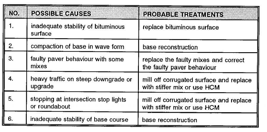

69 66


70 5.2 Surface defects in detail. 67


71 68

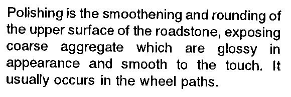


72 69


73 5.3 Patches And Potholes 70

74 5.4 Edge Defects In Detail 71


75 5.5 Causes And Remedies Of Shear Cracks 72
76 III year / V Sem Civil Engineering UNIT-I HIGHWAY PLANNING AND ALIGNMENT PART- A (2 Marks) 1. Define central road fund? On the recommendation of Jayakar Committee, a Central Road Fund came into existence on 1st march 1929, Upon the authority of a resolution adopted by the Indian legislature. 2. Define National Highway Act 1956? In 1956, National Highway act was passed declaring the National Highways and empowering the central Govt. to declare any other highway to be NH. This act came into force with effect from 15th April Explain CRRI? CRRI- The central Road Research Institute Delhi in 1950 It is an organ of the council of scientific and industrial research, and in function include. 4. Write Short notes on Highway Research Board? This board was set up by I.R.C in 1973 to give proper direction and guidance to road research work in India. 5. What are classified roads in Nagpur plan? 1. National Highways (NH) 2. State Highways (SH) 3. District Roads: (1) Major district Roads (2) Other district Roads 4. Village roads. 6. Define Express ways? These roads are of higher, day than National highway. There are Such roads on which only font moving vehicles like car and jeeps are classified. 7. What are the modified classifications of Road system by Third RDP ( )? 1. Primary System 2. Secondary System 3. Tertiary system 8. What are types of Road patterns? 1. Rectangular (or) Black pattern. 2. Radial (or) Star and black pattern. 9. Write short notes or Nagpur plan (or) its 20-year Road plan. The first attempt for proper Scientific planning of roads in India, Wan made in chief Engineers conference held at Nagpur in Nagpur conference finalized at 20 years ( ) road development plan. 10. Write short notes on Second twenty year road plan ( ) A Second road development programmer ( ) was finalized by the chief engineers connected with road development, both at centre and Staten in a meeting held at Hyde Chad in What are the fundamental principles of alignment? 1. Length of road should be shortest 2. The Proposed road should form a most economical line. 1 R.Arthanareswaran
77 III year / V Sem Civil Engineering 3. The alignment should provide corny. 12. What are the function which control the selection of alignment? 1. Volume and type of traffic 2. Obligatory points 3. Canal river (or) railway crossings 4. Geotechnical standard to he adopted 13. Define obligatory point? Obligatory points are such points which act to control points in highway alignment. 14. What are special considerations for him road alignment? 1. Stability 2. Drainage 3. Geometric standard 4. Deep writing and heavy fillings should he avoided. 15. What are the various types of engineering surveys? 1. Map shady 2. Reconnaissance survey 3. Preliminary survey 4. Detailed Survey 16. What are two type of road project? 1. A new highway Project 2. Re-alignment (or) revenging Highway project 17. What are head involved in Highway Geometric? 1. Cross Section eleventh like camber, Super elevation 2. Sight distance character sight like stopping sight distance, overtaking sight distance etc. 3. Horizontal and vertical alignments 18. Define camber? Traverse slope given to the road surface in called camber. It is provided mainly to drain off rain water from the road surface. 19. What are the factors deepens on camber? 1. Account of Surface 2. Type ground surface 20. What camber recommended in WBM Road? Water Bound Macadam road 1 to 33 (3%) 1 in 40 (2.5%). 21. What camber recommended in bihiminour road? Bihiminour surface 1 in 40 (2.5%) 1 in 50 (2%) 22. What camber recommended in cement concrete Road? Cement concrete Road 1 in 50 (2%) 1 in 60 (1.7%) 23. What are the different types of camber? 1. Parabolic camber 2. Sloped camber 3. Composite camber 24. Define carriage way width? Metal led puce strip of road meant for vehicular traffic movement in called carriage 2 R.Arthanareswaran
78 III year / V Sem Civil Engineering way. 25. Define dual carriageways? Each portion of the carriageway is reserved for traffic moving in opposite direction. Such carriage ways are called dual carriageways. 26. What are the width of carriage way in meteor two lane without raised wert state highways? State highways 7.0 m 27. Write note on high speed barrier herb? This herb is 23cm to 45cm to height. This herb is mainly used at initial location such as bridge and hill roads. 28. Define formation width? Formation width is also called road way. It is the sum of width of carriage way shoulders, and separations it provided 29. Define Right of way:- Area to the acquired along the road alignment in called right of way. 30. What are the important modifications made in Macadam s method with respect to the other methods? Following are the important modifications made in Macadam s method. i) Realizing the importance of subgrade drainage and compaction, the subgrades were prepared with sufficient cross slope. ii) Heavy foundation stones were replaced with broken stones and with adequate drainage arrangements. iii) The total thickness is comparatively less and the order of 25 cm. iv) The size of broken stones used for the layer was based on the stability under animal drawn vehicles. 31. What are the objectives of Central Road Fund? As per the recommendation of Jayakar Committee, a Central Road Fund was created in 1 st march The Consumers of petrol were then charged an extra levy of 2.64 paisa per liter (i.e., two annas per gallon). Twenty percent of the revenue collected through the fund was retained as Central Reserve and the balance allotted to the various states based on the actual petrol consumptions. 32. State the principles of highway financing. Highway financing is concerned with the sources and distribution of the money that is obtained for highway purposes. Thus the basic principle in highway financing is that the money spent on the construction and maintenance must be recovered from the roads users. 33. Mention the functions of medians in urban roads. Separators or medians are provided to prevent the head on collision between two vehicles moving in opposite directions in the adjacent lanes. These medians may be in the form of pavement markings, physical dividers or area separators. Out of these three pavement making is the respect. 3 R.Arthanareswaran
79 III year / V Sem Civil Engineering 1.Nagpur classification PART B (16 Marks) In Nagpur road classification, all roads were classified into five categories as National highways, State highways, Major district roads, Other district roads and village roads. National highways They are main highways running through the length and breadth of India connecting major ports, foreign highways, capitals of large states and large industrial and tourist centers including roads required for strategic movements. It was recommended by Jayakar committee that the National highways should be the frame on which the entire road communication should be based. All the national highways are assigned the respective numbers. For e.g. the highway connecting Delhi-Ambala-Amritsar is denoted as NH-1 (Delhi-Amritsar), where as a bifurcation of this highway beyond Fullundar to Srinagar and Uri is denoted as NH-1_A. They are constructed and maintained by CPWD. The total length of National highway in the country is 58,112 Kms, and constitute about 2% of total road networks of India and carry 40% of total traffic. State highways They are the arterial roads of a state, connecting up with the national highways of adjacent states, district head quarters and important cities within the state They also serve as main arteries to and from district roads. Total length of all SH in the country is 1,37,119 Kms. Major district roads Important roads with in a district serving areas of production and markets, connecting those with each other or with the major highways. India has a total of 4,70,000 kms of MDR. Other district roads Roads serving rural areas of production and providing them with outlet to market centers or other important roads like MDR or SH. Village roads They are roads connecting villages or group of villages with each other or to the nearest road of a higher category like ODR or MDR. India has 26,50,000 kms of ODR+VR out of the total 33,15,231 kms of all type of roads. 4 R.Arthanareswaran
80 III year / V Sem Civil Engineering 2.Alignment The position or the layout of the central line of the highway on the ground is called the alignment. Horizontal alignment includes straight and curved paths. Vertical alignment includes level and gradients. Alignment decision is important because a bad alignment will enhance the construction, maintenance and vehicle operating costs. Once an alignment is fixed and constructed, it is not easy to change it due to increase in cost of adjoining land and construction of costly structures by the roadside. Requirements The requirements of an ideal alignment are The alignment between two terminal stations should be short and as far as possible be straight, but due to some practical considerations deviations may be needed. The alignment should be easy to construct and maintain. It should be easy for the operation of vehicles. So to the maximum extend easy gradients and curves should be provided. It should be safe both from the construction and operating point of view especially at slopes, embankments, and cutting. It should have safe geometric features. The alignment should be economical and it can be considered so only when the initial cost, maintenance cost, and operating cost are minimum. Factors controlling alignment We have seen the requirements of an alignment. But it is not always possible to satisfy all these requirements. Hence we have to make a judicial choice considering all the factors. The various factors that control the alignment are as follows: Obligatory points: These are the control points governing the highway alignment. These points are classified into two categories. Points through which it should pass and points through which it should not pass. Some of the examples are: o Bridge site: The bridge can be located only where the river has straight and permanent path and also where the abutment and pier can be strongly founded. The road approach to the bridge should not be curved and skew crossing should be avoided as possible. Thus to locate a bridge the highway alignment may be changed. o Mountain: While the alignment passes through a mountain, the various alternatives are to either construct a tunnel or to go round the hills. The suitability of the alternative depends on factors like topography, site conditions and construction and operation cost. 5 R.Arthanareswaran
81 III year / V Sem Civil Engineering o Intermediate town: The alignment may be slightly deviated to connect an intermediate town or village nearby. These were some of the obligatory points through which the alignment should pass. Coming to the second category, that is the points through which the alignment should not pass are: Religious places: These have been protected by the law from being acquired for any purpose. Therefore, these points should be avoided while aligning. Very costly structures: Acquiring such structures means heavy compensation which would result in an increase in initial cost. So the alignment may be deviated not to pass through that point. Lakes/ponds etc: The presence of a lake or pond on the alignment path would also necessitate deviation of the alignment. Traffic: The alignment should suit the traffic requirements. Based on the origindestination data of the area, the desire lines should be drawn. The new alignment should be drawn keeping in view the desire lines, traffic flow pattern etc. Geometric design: Geometric design factors such as gradient, radius of curve, sight distance etc. also govern the alignment of the highway. To keep the radius of curve minimum, it may be required to change the alignment. The alignments should be finalized such that the obstructions to visibility do not restrict the minimum requirements of sight distance. The design standards vary with the class of road and the terrain and accordingly the highway should be aligned. Economy: The alignment finalized should be economical. All the three costs i.e. construction, maintenance, and operating cost should be minimum. The construction cost can be decreased much if it is possible to maintain a balance between cutting and filling. Also try to avoid very high embankments and very deep cuttings as the construction cost will be very higher in these cases. 3. Explain Jayakar committee recommendations. The first World war period and that immediately following it found a rapid growth in motor transport. So need for better roads became a necessity. For that, the Government of India appointed a committee called Road development Committee with Mr.M.R. Jayakar as the chairman. This committee came to be known as Jayakar committee Jayakar Committee In 1927 Jayakar committee for Indian road development was appointed. The major recommendations and the resulting implementations were: Committee found that the road development of the country has become beyond the capacity of local governments and suggested that Central government should take the proper charge considering it as a matter of national interest. 6 R.Arthanareswaran
82 III year / V Sem Civil Engineering They gave more stress on long term planning programme, for a period of 20 years (hence called twenty year plan) that is to formulate plans and implement those plans with in the next 20 years. One of the recommendations was the holding of periodic road conferences to discuss about road construction and development. This paved the way for the establishment of a semi-official technical body called Indian Road Congress (IRC) in 1934 The committee suggested imposition of additional taxation on motor transport which includes duty on motor spirit, vehicle taxation, license fees for vehicles plying for hire. This led to the introduction of a development fund called Central road fund in This fund was intended for road development. A dedicated research organization should be constituted to carry out research and development work. This resulted in the formation of Central Road Research Institute (CRRI) in Write about the Lucknow road congress 1984 This plan has been prepared keeping in view the growth pattern envisaged in various fields by the turn of the century. Some of the salient features of this plan are as given below: This was the third 20 year road plan ( ). It is also called Lucknow road plan. It aimed at constructing a road length of 12 lakh kilometres by the year 1981 resulting in a road density of 82kms/100 sq.km The plan has set the target length of NH to be completed by the end of seventh, eighth and ninth five year plan periods. It aims at improving the transportation facilities in villages, towns etc. such that no part of country is farther than 50 km from NH. One of the goals contained in the plan was that expressways should be constructed on major traffic corridors to provide speedy travel. Energy conservation, environmental quality of roads and road safety measures were also given due importance in this plan. 1. (i) State the construction steps of Macadam method of road formation. (ii) Compare with Telford road construction. 2. How urban and rural roads are classified? Explain. 3. State and explain the various types of kerbs. 4. (i) What are the requirements of an ideal highway alignment? Discuss briefly. (ii)compare Conventional methods with modern methods in Highway. 5. (i) Discuss in detail about the obligatory points controlling highway alignment. (ii) Explain 1. GIS 2. GPS 3. Remote sensing 4. Total station 7 R.Arthanareswaran
83 III year / V Sem Civil Engineering 6. Define MORTH. Write the importance of MORTH. 7. (i) Briefly explain the role of MORTH and IRC in highway development. (ii) State and explain the economic factors influencing highway alignments. 8. Draw typical cross sections of urban and rural roads. 9. Draw a neat sketch and explain the cross section of an urban arterial. 10. With a neat sketch explain the cross-sectional elements of a 2 lane rural road on embankment. 11. Write the salient features of Nagpur Road plan. 12. Describe the various steps in a highway project. 13. Explain the different components of the National Highway Development Programme (NHDP). 14. Describe the classification of urban roads in India. Give the cross section of urban Arterial Street with all its features. 15. (i) Explain the activities of National Highway Authority of India. (ii) Explain the procedure for carrying out road alignment using remote sensing and GIS technique. 16. Compare the three Twenty year road development plan in India. Also discuss the merits of each one of them. 17. Explain in detail about second twenty year road plan. 18. Write a brief notes on: a. Central Road Fund (CRF). b. Indian Roads Congress (IRC). c. Motor vehicle act. d. Central Road Research Institute (CRRI). e. Highway Research Board (HRB). f. Nagpur road plan. g. National Highway Authority of India (NHAI). 8 R.Arthanareswaran
84 III year / V Sem Civil Engineering UNIT-II GEOMETRIC DESIGN OF HIGHWAYS PART- A (2 Marks) 1. Define sight distance? Sight distance in the actual length of road over which a driver sitting at a specified height in a vehicle can see objects either moving (or) stationary on the road surface. 2. What are classifications of sight distance depending upon the situation? 1. Stopping sight distance 2. Sate overtaking sight distance 3. Sight distance at intersection 3. Define S.S.D? Stopping sight distance is the minimum distance required with in which a vehicle moving at designed speed can be stopped without colliding with a stationary object on the road surface. 4. What is the height of driver eye above the road surface? IRC recommended height of driver eye is 1.22m. 5. Define reaction time:- It is the time in seconds which a driver can take from the instant the objects visible to him to the instant the brakes are effectively applied. 6. Define perception period? Perception period is the time taken by an average driver to realize a danger a head before actually trying to apply the breaker. 7. Define overtaking sight distance (OSD) The distance visible to the driver of a vehicle intending to overtake another slow moving vehicle, without causing any inconvenience (or) possibility of accident to the traffic in the opposite direction in called overtaking sight distance (or) safe passing sight distance. 8. Define design speed? Design speed can be defined as the speed which is permissible for safe and comfortable driving on a given surface of the highway. 9. What are the two effects of centrifugal force? 1. Tendency to overturn the vehicle. 2. Tendency to skid the vehicle laterally. 10. Define super elevation? The outer edge of the road in raised above the inner edge called super elevation (or) cant (or) banking. 11. What is the relation between super elevation, continuant of friction and centrifugal force e+f=v 2 /9.8R e = super elevation whose value is taken an 40 (or) 1/15 f = Lateral frictional coefficient whose value in R = Radian of curve in metros. g = 9.8 V = speed of vehicle in m/sec. 9 R.Arthanareswaran
85 III year / V Sem Civil Engineering 13. Define horizontal curve? It is a curve in plan to provide change in the direction of the central time by the road surface. 14. What are the factors attesting the design of curve? 1. Design speed of the vehicle 2. Allowable friction 3. Maximum allowable super elevation. 4. Permissible centrifugal ration. 15. Define vertical curve? It is a curve in the longitudinal section of a highway to provide a easy change of the gradient. 16. What are curve used in a highway. 1. Circular curve 2. Transition curve 3. Parabolic curve 17. What is the value of radian of the simple curve? R= 1720m app 18. Define compound curve? A compound curve currish of a serial of hoot (or) more simple curve that run in the same direction and joint at common tangent point. 19. Define Reverse curve? A reverse curve consist of two simple curve opposite direction that point at the common tangent point. This common point in called the point of reverse curve 20. What are the types of transition curve? 1. True spiral (or clothed. 2. cubic spiral. 3. cubic parabolic. 4. Lemniscate s. 21. What are characteristics of Transition curve? 1. It should meet the straight path tangentially 2. It should meet the circular curve tangentially 22. What is the equation of a spiral transition curve? Ls = m Ö Q Where m = Ö2RL = a constant Q = tangent of deflection angle in radians 23. How many methods to determine the length of transition curve? (1) By the rate of charge of radial acceleration (2) By empirical formula 24. Define gradient? It is the rate of rise (or) fall of road level along if length 25. What are the factors governs the gradient? (1) characteristics of the traffic. (2) Physical factors of the site such a drainage, safety, (3) Bridge, approach Road and railway Line intersection etc. 10 R.Arthanareswaran
86 III year / V Sem Civil Engineering 26. What are different types of gradient? (1). Maximum gradient (2). Puling gradient (3). Limiting gradient (4). Exceptional gradient 27. What are the driaclvantager of Exceptional gradient? (1). More fuel consumption (2). More friction losses (3). Efficiency of engine reducer (4). Early fatigue to animals. 28. What are the hyper of vertical curve? 1. Summit curve 2. Valley curve 29. what is the minimum Radian of vertical curve? The minimum ration of the curve is given by L R = --- Q 30. What is the length of valley curve? L= 0.38 (NV 3) ½ L = Total Length of valley curve N = Deviation angle v = Design speed in triumph PART B (16 Marks) 1.Types of gradient Many studies have shown that gradient upto seven percent can have considerable effect on the speeds of the passenger cars. On the contrary, the speeds of the heavy vehicles are considerably reduced when long gradients as flat as two percent is adopted. Although, flatter gradients are desirable, it is evident that the cost of construction will also be very high. Therefore, IRC has specified the desirable gradients for each terrain. However, it may not be economically viable to adopt such gradients in certain locations, steeper gradients are permitted for short duration. Different types of grades are discussed below and the recommended type of gradients for each type of terrain and type of gradient is given in table 1. Table 1: IRC Specifications for gradients for different roads Terrain Ruling Limitings Exceptional Plain/Rolling Hilly Steep Ruling gradient, limiting gradient, exceptional gradient and minimum gradient are some types of gradients which are discussed below. Ruling gradient 11 R.Arthanareswaran
87 III year / V Sem Civil Engineering The ruling gradient or the design gradient is the maximum gradient with which the designer attempts to design the vertical profile of the road. This depends on the terrain, length of the grade, speed, pulling power of the vehicle and the presence of the horizontal curve. In flatter terrain, it may be possible to provide flat gradients, but in hilly terrain it is not economical and sometimes not possible also. The ruling gradient is adopted by the designer by considering a particular speed as the design speed and for a design vehicle with standard dimensions. But our country has a heterogeneous traffic and hence it is not possible to lay down precise standards for the country as a whole. Hence IRC has recommended some values for ruling gradient for different types of terrain. Limiting gradient This gradient is adopted when the ruling gradient results in enormous increase in cost of construction. On rolling terrain and hilly terrain it may be frequently necessary to adopt limiting gradient. But the length of the limiting gradient stretches should be limited and must be sandwiched by either straight roads or easier grades. Exceptional gradient Exceptional gradient are very steeper gradients given at unavoidable situations. They should be limited for short stretches not exceeding about 100 metres at a stretch. In mountainous and steep terrain, successive exceptional gradients must be separated by a minimum 100 metre length gentler gradient. At hairpin bends, the gradient is restricted to 2.5%. Critical length of the grade The maximum length of the ascending gradient which a loaded truck can operate without undue reduction in speed is called critical length of the grade. A speed of 25 kmph is a reasonable value. This value depends on the size, power, load, grad-ability of the truck, initial speed, final desirable minimum speed Minimum gradient This is important only at locations where surface drainage is important. Camber will take care of the lateral drainage. But the longitudinal drainage along the side drains require some slope for smooth flow of water. Therefore minimum gradient is provided for drainage purpose and it depends on the rain fall, type of soil and other site conditions. A minimum of 1 in 500 may be sufficient for concrete drain and 1 in 200 for open soil drains are found to give satisfactory performance. 3. How is super-elevation attained? Elimination of the crown of the cambered section by: Rotating the outer edge about the crown : The outer half of the cross slope is rotated about the crown at a desired rate such that this surface falls on the same plane as the inner half. Shifting the position of the crown: This method is also known as 12 R.Arthanareswaran
88 III year / V Sem Civil Engineering diagonal crown method. Here the position of the crown is progressively shifted outwards, thus increasing the width of the inner half of cross section progressively. Rotation of the pavement cross section to attain full super elevation by: There are two methods of attaining superelevation by rotating the pavement Rotation about the center line: The pavement is rotated such that the inner edge is depressed and the outer edge is raised both by half the total amount of superelevation, i.e., by E=2 with respect to the centre. Rotation about the inner edge: Here the pavement is rotated raising the outer edge as well as the centre such that the outer edge is raised by the full amount of superelevation with respect to the inner edge 4. What are the factors affecting Sight distance? The most important consideration in all these is that at all times the driver traveling at the design speed of the highway must have sufficient carriageway distance within his line of vision to allow him to stop his vehicle before colliding with a slowly moving or stationary object appearing suddenly in his own traffic lane The computation of sight distance depends on: Reaction time of the driver Reaction time of a driver is the time taken from the instant the object is visible to the driver to the instant when the brakes are applied. The total reaction time may be split up into four components based on PIEV theory. In practice, all these times are usually combined into a total perception-reaction time suitable for design purposes as well as for easy measurement. Many of the studies show that drivers require about 1.5 to 2 secs under normal conditions. However, taking into consideration the variability of driver characteristics, a higher value is normally used in design. For example, IRC suggests a reaction time of 2.5 secs. Speed of the vehicle The speed of the vehicle very much affects the sight distance. Higher the speed, more time will be required to stop the vehicle. Hence it is evident that, as the speed increases, sight distance also increases. Efficiency of brakes The efficiency of the brakes depends upon the age of the vehicle, vehicle characteristics etc. If the brake efficiency is 100%, the vehicle will stop the moment 13 R.Arthanareswaran
89 III year / V Sem Civil Engineering the brakes are applied. But practically, it is not possible to achieve 100% brake efficiency. Therefore the sight distance required will be more when the efficiency of brakes are less. Also for safe geometric design, we assume that the vehicles have only 50% brake efficiency. Frictional resistance between the tyre and the road The frictional resistance between the tyre and road plays an important role to bring the vehicle to stop. When the frictional resistance is more, the vehicles stop immediately. Thus sight required will be less. No separate provision for brake efficiency is provided while computing the sight distance. This is taken into account along with the factor of longitudinal friction. IRC has specified the value of longitudinal friction in between 0.35 to 0.4. Gradient of the road. Gradient of the road also affects the sight distance. While climbing up a gradient, the vehicle can stop immediately. Therefore sight distance required is less. While descending a gradient, gravity also comes into action and more time will be required to stop the vehicle. Sight distance required will be more in this case. 1. What are the objectives of widening of road pavement at horizontal curves? Derive an expression for the extra widening 2. (i) The speed of overtaking and over taken vehicles are70 and 40 kmph, respectively on a two way traffic road. If the acceleration of overtaking vehicle is 0.99m/sec 2 a. Calculate safe overtaking sight distance b. Mention the minimum length of overtaking zone and c. Draw a neat-sketch of the overtaking zone and show position of sign posts. (ii) What is overtaking sight distance and intermediate sight distance? 3. (i) Derive the formula for the radius of horizontal curve. (ii) Why do you provide the extra widening on horizontal curves? 4. Describe the various types of horizontal curves. 5. Under what circumstances summit curves are provided. 6. What are the objectives of providing transition curves in the horizontal alignment of highway curves? Mention the method of designing transition curve length. 7. What are the objectives of widening of road pavement at horizontal curves? Derive an expression for the extra widening. 8. What are the objects of extra widening of pavements at horizontal highway curves? Mention the recommended method of design and introduction in the field. 9. A valley curve is formed by a descending gradient of 1 in 25 meeting an ascending gradient of 1 in 30. Design the length of valley curve to fulfill both comfort condition for a design speed of 80 kmph (c = 0.6 mtr/sec 3 ) and a head sight distance 14 R.Arthanareswaran
90 III year / V Sem Civil Engineering of 127 m for this speed. 10. (i) Compute the stopping sight distance on a highway with a design speed of 80 kph, if the highway is on an upgrade of 2%. (ii) Outline the design elements of hill roads. 11. (i) What is the need for transition curve? How its length is determined? (ii) Explain the procedure for calculating the length of valley curve. 12. (i) Explain the factors influencing the geometric design of hill roads. (ii) Calculate the SSD for design speed of 70 kmph for two way traffic and one way traffic road. Take reaction time = 2.5 seconds and coefficient of friction = (1) Derive the formula for calculating super elevation on horizontal curve. (2) Explain the factors influencing overtaking sight distance 14. Calculate the stopping sight distance required to avoid head on collision of two cars approaching from opposite directions at a speed of 75 kmph and 80 kmph. Assume that the reaction time of divers be 2.5 secs and coefficient between road surface and tyros be (i) Distinguish between overtaking sight distance and intermediate sight distance. How will you calculate these? (ii) What is the super elevation to be provided on a horizontal curve on a National Highway in plain terrain (Hint: Design speed =100 kph), if the curve has a radius of 310 m? 16. (i) Why is super elevation provided for pavements in curves? Explain the factors influencing it. (ii) Why are extra widening of pavements requited in curve? 17. (i) Calculate the stopping sight distance for the design speed of 60 kmph for a twoway traffic road and an one-way traffic road, Take the reaction time of driver as 2.5 seconds and the coefficient of friction as (ii) Under what circumstances summit curves are provided. 18. (i) Calculate the stopping sight distance to avoid head on collision of two cars approaching from opposite directions at 100k/hr and 80 k/hr. Make suitable assumptions. (ii) A highway width 7.5 m of radius 150 m, with a speed of 130 km/hr and the length of wheel base is 7.0 m. Find out the extra widening required. 19. Calculate the stopping sight required to avoid head on collision of two cars approaching from opposite directions at a speed of 75 kmph and 85 kmph. Assume the reaction time of drivers be 2.5 secs. And the coefficient of friction between road surface and tyres is Calculate the minimum set back distance required on a two lane highway curve radius 400 m so as to provide an intermediate sight distance 180 m, assuming the length of the curve to be greater than SD (200 m). 21. A valley curve is formed due to two gradients +2.5% and 1.75%. If the design speed of this highway is 80 kmph, determine the stopping sight distance and design the valley curve to fulfill both comfort and head light sight distance conditions. 15 R.Arthanareswaran
91 III year / V Sem Civil Engineering UNIT-III FLEXIBLE AND RIGID PAVEMENTS PART- A (2 Marks) 1. What are the materials required for W.B.M roads? 1. Coarse aggregate. 2. Screenings. 3. Filler materials 2. What are types of bituminous road? 1. Surface dressing 2. Bituminous bound macadam 3. Define seal coat? Premised snail bitumen (or) surface dressing type seal coat is applied either immediately (or) after a few days. 4. What are methods adopted consummation of cement concrete pavement? 1. Cement grout method 2. Rolled concrete method. 3. Cement connate slab method 5. What types of join provided in cement concrete pavements? 1. Expansion joint 2. Contraction joint 3. Warping joint. 6. What material used as joint Filler? 1. Soft wood 2. Impregnated fiber board 3. Cork (or) cork bound with bitumen 4. Coir fiber 7. What mate rich used a joint sealer? 1. Birdmen 2. Rubén bitumen 8. Write short notes on Hair pin bend? A hair pin bend should he located on the hill side having the minimum slope and maximum stability It should be sate against land slide and ground water. Hair pin bends with long arms and further spacing should he provided. 9. What are the methods of pavement? 1. Flexible pavement 2. Rigid pavement 10. What are the components of a fallible pavement? 1. Soil sub grade 2. Sub base course 3. Base course 4. Wearing course 11. Define sub grade? The soil sub grade in a layer of natural soil prepared to receive the other lays of the pavement. 16 R.Arthanareswaran
92 III year / V Sem Civil Engineering 12. What properties posses soil sub grade? a. strength b. Drainage c. Ease of compaction d. permanency of compaction etc. 13. What are tests conducted the strength properties of the sub grade? 1. California bearing ratio tests 2. California resistance value test 3. Plate bearing test 4. Trysail shear test 14. Define bone course? It is the foundation layer, designed for the structural stability. The main function of the bare course in edible pavements is to improve the load supporting capacity by distributing the load through a finite ethicalness. 15. Define leaving course? It is that component of pavement with which the wheels of vehicular are in archival contain. 16. What are the factors attaching stability of pavement? a. Traffic factors. b. Mosher factors. c. Climatic factors. d. Soil factors e. Stets dissipation factors. PART B (16 Marks) 1.Comparison of Flexible and Rigid Pavement 1. Deformation in the sub grade is transferred to the upper layers 2. Design is based on load distributing characteristics of the component layers 3. Have low flexural strength 4. Load is transferred by grain to grain contact 5. Have low completion cost but repairing cost is high 6. Have low life span 7. Surfacing cannot be laid directly on the sub grade but a sub base is needed 1. Deformation in the sub grade is not transferred to subsequent layers 2. Design is based on flexural strength or slab action 3. Have high flexural strength 4. No such phenomenon of grain to grain load transfer exists 5. Have low repairing cost but completion cost is high 6. Life span is more as compare to flexible 7. Surfacing can be directly laid on the sub grade 17 R.Arthanareswaran
93 III year / V Sem Civil Engineering 2.What are the Types of Flexible Pavements? The following types of construction have been used in flexible pavement: Conventional layered flexible pavement, Full - depth asphalt pavement, and Contained rock asphalt mat (CRAM). Conventional flexible pavements are layered systems with high quality expensive materials are placed in the top where stresses are high, and low quality cheap materials are placed in lower layers. Full - depth asphalt pavements are constructed by placing bituminous layers directly on the soil sub-grade. This is more suitable when there is high traffic and local materials are not available. Contained rock asphalt mats are constructed by placing dense/open graded aggregate layers in between two asphalt layers. Modified dense graded asphalt concrete is placed above the sub-grade will significantly reduce the vertical compressive strain on soil sub-grade and protect from surface water. 3.What are the Typical layers of a flexible pavement? Typical layers of a conventional flexible pavement includes seal coat, surface course, tack coat, binder course, prime coat, base course, sub-base course, compacted sub-grade, and natural subgrade. Seal Coat: Seal coat is a thin surface treatment used to water-proof the surface and to provide skid resistance. Tack Coat: Tack coat is a very light application of asphalt, usually asphalt emulsion diluted with water. It provides proper bonding between two layer of binder course and must be thin, uniformly cover the entire surface, and set very fast. Prime Coat: Prime coat is an application of low viscous cutback bitumen to an absorbent surface like granular bases on which binder layer is placed. It provides bonding between two layers. Unlike tack coat, prime coat penetrates into the layer below, plugs the voids, and forms a water tight surface. Surface course Surface course is the layer directly in contact with traffic loads and generally contains superior quality materials. They are usually constructed with dense graded asphalt concrete(ac). The functions and requirements of this layer are: It provides characteristics such as friction, smoothness, drainage, etc. Also it will prevent the entrance of excessive quantities of surface water into the underlying base, sub-base and sub- 18 R.Arthanareswaran
94 III year / V Sem Civil Engineering grade, It must be tough to resist the distortion under traffic and provide a smooth and skid- resistant riding surface, It must be water proof to protect the entire base and sub-grade from the weakening effect of water. Binder course This layer provides the bulk of the asphalt concrete structure. It's chief purpose is to distribute load to the base course The binder course generally consists of aggregates having less asphalt and doesn't require quality as high as the surface course, so replacing a part of the surface course by the binder course results in more economical design. Base course The base course is the layer of material immediately beneath the surface of binder course and it provides additional load distribution and contributes to the sub-surface drainage It may be composed of crushed stone, crushed slag, and other untreated or stabilized materials. Sub-Base course The sub-base course is the layer of material beneath the base course and the primary functions are to provide structural support, improve drainage, and reduce the intrusion of fines from the sub-grade in the pavement structure If the base course is open graded, then the sub-base course with more fines can serve as a filler between sub-grade and the base course A sub-base course is not always needed or used. For example, a pavement constructed over a high quality, stiff sub-grade may not need the additional features offered by a sub-base course. In such situations, sub-base course may not be provided. Sub-grade The top soil or sub-grade is a layer of natural soil prepared to receive the stresses from the layers above. It is essential that at no time soil sub-grade is overstressed. It should be compacted to the desirable density, near the optimum moisture content. 19 R.Arthanareswaran
95 III year / V Sem Civil Engineering 4. What are the different types of road surfaces? Unsurfaced earthen roads, or cart-track Unsurfaced earthen roads upgrades with natural soil from borrow pits and attention to drainage, and compaction is by traffic Dry aggregate and sand-clays mix, in which the the former act as wear resistant and the latter as natural binder Water-bound macadam, the above constituents, mixed together (pre-mix or in-situ) with water and com-pacted to improve the strength Oiled roads, introduced to reduce dust by bitumen stabilized soils Seal coat: the base course is protected from traffic and moisture by sealing the surface with a thin lm of bitumen aggregate mix, which is structurally strong surface for pneumatic-tyred traffic. This is provided on firm and smooth base course after a tack coat using cutback bitumen or bitumen emulsions with a penetration of 5 mm. Asphaltic concrete: Traffic and the axle configuration are increasing very much which raises demand for the new type of pavement which can meet the above requirements. The asphaltic concrete is one which is the high dense graded premix and it is termed as the highest quality pavement surface course. Bitumen mix or asphalt mix overlays of minimum mm to as high as mm or even more. 5. What are the Design procedures for flexible pavement For flexible pavements, structural design is mainly concerned with determining appropriate layer thickness and composition. The main design factors are stresses due to traffic load and temperature variations. Two methods of flexible pavement structural design are common today: Empirical design and mechanistic empirical design. Empirical design An empirical approach is one which is based on the results of experimentation or experience. Some of them are either based on physical properties or strength parameters of soil subgrade. An empirical approach is one which is based on the results 20 R.Arthanareswaran
96 III year / V Sem Civil Engineering of experimentation or experience. An empirical analysis of flexible pavement design can be done with or with out a soil strength test. An example of design without soil strength test is by using HRB soil classification system, in which soils are grouped from A-1 to A-7 and a group index is added to differentiate soils within each group. Example with soil strength test uses McLeod, Stabilometer, California Bearing Ratio (CBR) test. CBR test is widely known and will be discussed. Mechanistic- Empirical Design Empirical-Mechanistic method of design is based on the mechanics of materials that relates input, such as wheel load, to an output or pavement response. In pavement design, the responses are the stresses, strains, and deflections within a pavement structure and the physical causes are the loads and material properties of the pavement structure. The relationship between these phenomena and their physical causes are typically described using some mathematical models. Along with this mechanistic approach, empirical elements are used when defining what value of the calculated stresses, strains, deflections result in pavement failure. The relationship between physical phenomena and pavement failure is described by empirically derived equations that compute the number of loading cycles to failure. and 1. Briefly give the IRC Recommendations useful in the design of cement concrete pavement. 2. Explain in detail about the IRC method of flexible pavement design. Discuss limitation of this method. 3. Explain the methods of design of Flexible pavement by CBR method. 4. Discuss the advantage and limitations of CBR method of design. 5. Differentiate between Flexible and rigid Pavement (or) Compare Flexible and Rigid Pavement. 6. Explain the design consideration for spacing of expansion and construction Joints. 7. What are the objectives of joints in cement concrete pavement? Sketch the different types of joints used in pavement construction. Indicate the principle of design. 8. Explain mud pumping. What are the causes for mud pumping and how it can be prevented? 9. Define ESWL and Lane distribution factor and explain their significance. 10. Describe the factors influencing the design of pavements. 11. Explain the recommended design procedure for design of rigid pavements by 21 R.Arthanareswaran
97 III year / V Sem Civil Engineering IRC. 12. List the different stresses induced in cement concrete pavements. Discuss the critical combination of these stresses. 13. How will you calculate the Equivalent Single Wheel Load for a given combination of wheel loads? 14. Explain the IRC method of design of rigid pavements. 15. Explain the factors to be considered in the design of pavements. 16. State how variations in climatic conditions affect the design of pavements. 17. What is equivalent single wheel load? Explain briefly. 18. Design the pavement of a plain cement concrete 7m wide. Use IRC Recommendations where ever applicable. Adopt expansion joint gap 20mm and Maximum variation in temperature between summer and winter is 40 c.present Traffic intensity is 1050 veh/day of weight more than 3T. Modulus of reaction of sub base 7 kg/cm³.e for concrete = 3x10 5 kg/cm², µ = 0.15 and radius of contact area is 15 cm and design wheel load is 4100 kg. Temperature differential slab in the region is 17.3, 19.0 and 20.3 for thickness is of 15, 20 and 25cm respectively.( use design chart if necessary) 19. CBR value of sub grade is 4%. Calculate total thickness of pavement. Also calculated the thickness of sub base, base, wearing layer having CBR value of 15%, 80%, and 90% respectively. Use IRC accepted CBR curve D. (Use design chart) 20. Using the following data, design the flexible pavements layers CBR of the sub-grade soil = 5% CBR of poorly graded gravel sub-base = 15% CBR of WBM = 80% Design life = 15 years Annual rate of increase in the heavy vehicles = 7.5% No. of heavy vehicles per day during last count = 200 No. of years between the year of completion and year of last count = 3 years. Assume any other data found required 21. Design the flexible pavement for construction of new Highway with the following data. Number of commercial vehicles as per last count = 1000 Period of construction = 3 years Annual traffic growth rate = 8% Category of road = NH, two lane single carriageway Design life = 10 years. 22 R.Arthanareswaran
98 III year / V Sem Civil Engineering UNIT IV HIGHWAY MATERIALS AND CONSTRUCTION PRACTICE PART- A (2 Marks) 1. Define contact presume? Contact presume = 2. Define Rigidity factor? Rigidity factor = loud on wheel Contact area contact presume Type presume 3. What is ESUL? Equivalent Single Used Load 4. What understand by Repetition of load? The repeated loading may produce permanent and non uniform deformation of sub grade. 5. What are the causes of increase in moisture? 1. Percolation of surface water through Erath in the pavement surface. 2. Entry of water through edger of the pavement 3. Seepage 4. Capillary rise from high water table 6. What is meaning of frost heave? The terms frost heave return to rising up of the pavement portion. 7. What method is used for strengthening of flexible pavement? Benkelman Beam Reflection method. 8. What is the basic principle of Benkelman Beam deflection method? The deflection method is based on the concept that pavement section which have been conditioned by traffic elastically under a load. 9. What are the factors considered deformation under a given load? 1. Sub grade soil type 2. Soil mousier content and its compaction 3. Thickness of pavement layers 4. Drainage conditions. 10. What are factors causing stressor in slab? 1. Used loads 2. Cyclic changer in temperature 3. Changes in moisture 4. Volumetric changer in bare course. 11. Define hand aggregator give example? Hand aggregator are used to resist crushing effect and adverse weather effect (ex) granite trap 23 R.Arthanareswaran
99 III year / V Sem Civil Engineering 12. What is the user of soft aggregator? They can also be used in lower layer of good type of roads. Soft aggregator are usable in low cost road. 13. What are the proportions of aggregator? 1. Strength 2. Hardness 3. Toughens 4. Sound ness 5. shape of aggregate 6. Bushmen adhesion properly 7. Cementations 14. What are test for Road aggregator? 1. Abrasion test 2. Lost angler abrasion test 15. Define Elongation index? This test is also suitable for aggregate of size greater than 6.3mm and is carried our in the same way a how been explained in flakiness index PART B (16 Marks) 1. What are the Tests on soil? Sub grade soil is an integral part of the road pavement structure as it provides the support to the pavement from beneath. The sub grade soil and its properties are important in the design of pavement structure. The main function of the sub grade is to give adequate support to the pavement and for this the sub grade should possess sufficient stability under adverse climatic and loading conditions. Therefore, it is very essential to evaluate the sub grade by conducting tests. The tests used to evaluate the strength properties of soils may be broadly divided into three groups: Shear tests Bearing tests Penetration tests Shear tests are usually carried out on relatively small soil samples in the laboratory. In order to find out the strength properties of soil, a number of representative samples from different locations are tested. Some of the commonly known shear tests are direct shear test, triaxial compression test, and unconfined compression test. Bearing tests are loading tests carried out on sub grade soils in-situ with a load bearing area. The results of the bearing tests are influenced by variations in the soil properties within the stressed soil mass underneath and hence the overall stability of the part of the soil mass stressed could be studied. 24 R.Arthanareswaran

100 III year / V Sem Civil Engineering Penetration tests may be considered as small scale bearing tests in which the size of the loaded area is relatively much smaller and ratio of the penetration to the size of the loaded area is much greater than the ratios in bearing tests. The penetration tests are carried out in the field or in the laboratory. 2. Explain the Crushing test One of the model in which pavement material can fail is by crushing under compressive stress. A test is standardized by IS:2386 part-iv and used to determine the crushing strength of aggregates. The aggregate crushing value provides a relative measure of resistance to crushing under gradually applied crushing load. The test consists of subjecting the specimen of aggregate in standard mould to a compression test under standard load conditions (Figure 22:1). Dry aggregates passing through 12.5 mm sieves and retained 10 mm sieves are filled in a cylindrical measure of 11.5 mm diameter and 18 cm height in three layers. Each layer is tampered 25 times with at standard tamping rod. The test sample is weighed and placed in the test cylinder in three layers each layer being tampered again. The specimen is subjected to a compressive load of 40 tonnes gradually applied at the rate of 4 tonnes per minute. Then crushed aggregates are then sieved through 2.36 mm sieve and weight of passing material (W 2 ) is expressed as percentage of the weight of the total sample (W 1 ) which is the aggregate crushing value. Aggregate crushing value = W1x100 W2 A value less than 10 signifies an exceptionally strong aggregate while above 35 would normally be regarded as weak aggregates. 3. What are the Shape tests? The particle shape of the aggregate mass is determined by the percentage of flaky and elongated particles in it. Aggregates which are flaky or elongated are detrimental to 25 R.Arthanareswaran
101 III year / V Sem Civil Engineering higher workability and stability of mixes. Flakiness gauge The flakiness index is defined as the percentage by weight of aggregate particles whose least dimension is less than 0.6 times their mean size. Test procedure had been standardized in India (IS:2386 part-i). Elongation gauge The elongation index of an aggregate is defined as the percentage by weight of particles whose greatest dimension (length) is 1.8 times their mean dimension. This test is applicable to aggregates larger than 6.3 mm. This test is also specified in (IS:2386 Part-I). However there are no recognized limits for the elongation index. 4. Explain the California Bearing Ratio Test California Bearing Ratio (CBR) test was developed by the California Division of Highway as a method of classifying and evaluating soil-sub grade and base course materials for flexible pavements. CBR test, an empirical test, has been used to determine the material properties for pavement design. Empirical tests measure the strength of the material and are not a true representation of the resilient modulus. It is a penetration test wherein a standard piston, having an area of 3 in 2 (or 50 mm diameter), is used to penetrate the soil at a standard rate of 1.25 mm/minute. The pressure up to a penetration of 12.5 mm and it's ratio to the bearing value of a standard crushed rock is termed as the 26 R.Arthanareswaran
102 III year / V Sem Civil Engineering CBR. In most cases, CBR decreases as the penetration increases. The ratio at 2.5 mm penetration is used as the CBR. In some case, the ratio at 5 mm may be greater than that at 2.5 mm. If this occurs, the ratio at 5 mm should be used. The CBR is a measure of resistance of a material to penetration of standard plunger under controlled density and moisture conditions. The test procedure should be strictly adhered if high degree of reproducibility is desired. The CBR test may be conducted in re-moulded or undisturbed specimen in the laboratory. The test is simple and has been extensively investigated for field correlations of flexible pavement thickness requirement. Test Procedure The laboratory CBR apparatus consists of a mould 150 mm diameter with a base plate and a collar, a loading frame and dial gauges for measuring the penetration values and the expansion on soaking. The specimen in the mould is soaked in water for four days and the swelling and water absorption values are noted. The surcharge weight is placed on the top of the specimen in the mould and the assembly is placed under the plunger of the loading frame. Load is applied on the sample by a standard plunger with dia of 50 mm at the rate of 1.25 mm/min. A load penetration curve is drawn. The load values on standard crushed stones are 1370 kg and 2055 kg at 2.5 mm and 5.0 mm penetrations respectively. CBR value is expressed as a percentage of the actual load causing the penetrations of 2.5 mm or 5.0 mm to the standard loads mentioned above. Therefore, Two values of CBR will be obtained. If the value of 2.5 mm is greater than that of 5.0 mm penetration, the former is adopted. If the CBR value obtained from test at 5.0 mm penetration is higher than that at 2.5 mm, then the test is to be repeated for checking. If the check test again gives similar results, then higher value obtained at 5.0 mm penetration is reported as the CBR value. The average CBR value of three test specimens is reported as the CBR value of the sample. 27 R.Arthanareswaran
103 III year / V Sem Civil Engineering 5. What are the Desirable properties of aggregates? Strength The aggregates used in top layers are subjected to (i) Stress action due to traffic wheel load, (ii) Wear and tear, (iii) crushing. For a high quality pavement, the aggregates should posses high resistance to crushing, and to withstand the stresses due to traffic wheel load. Hardness The aggregates used in the surface course are subjected to constant rubbing or abrasion due to moving traffic. The aggregates should be hard enough to resist the abrasive action caused by the movements of traffic. The abrasive action is severe when steel tyred vehicles moves over the aggregates exposed at the top surface. Toughness Resistance of the aggregates to impact is termed as toughness. Aggregates used in the pavement should be able to resist the effect caused by the jumping of the steel tyred wheels from one particle to another at different levels causes severe impact on the aggregates. Shape of aggregates Aggregates which happen to fall in a particular size range may have rounded, cubical, angular, aky or elongated particles. It is evident that the flaky and elongated particles will 28 R.Arthanareswaran
104 III year / V Sem Civil Engineering have less strength and durability when compared with cubical, angular or rounded particles of the same aggregate. Hence too flaky and too much elongated aggregates should be avoided as far as possible. Adhesion with bitumen The aggregates used in bituminous pavements should have less affinity with water when compared with bitu-minous materials, otherwise the bituminous coating on the aggregate will be stripped o in presence of water. Durability The property of aggregates to withstand adverse action of weather is called soundness. The aggregates are sub-jected to the physical and chemical action of rain and bottom water, impurities there-in and that of atmosphere, hence it is desirable that the road aggregates used in the construction should be sound enough to withstand the weathering action Freedom from deleterious particles Specifications for aggregates used in bituminous mixes usually require the aggregates to be clean, tough and durable in nature and free from excess amount of at or elongated pieces, dust, clay balls and other objectionable material. Similarly aggregates used in Portland cement concrete mixes must be clean and free from deleterious substances such as clay lumps, chert, silt and other organic impurities. 1. Write down the construction steps for water bound macadam road. Explain with sketch. 2. Describe the construction steps for surface dressing (or) Bituminous concrete methods of Bituminous construction with sketch. 3. Enumerate the steps in the construction of cement concrete pavement. Explain with sketch. 4. Write short notes on (a) CBR test on soil (b) Field density test on soil. 5. Explain with sketch the following testing methods. (a) Penetration test on Bitumen (b) Softening point test on Bitumen (or) Briefly explain the penetration test and softening point test on Bitumen. 6. Explain with neat sketch of impact value test on aggregates. 7. Explain with neat sketch of Durability test on Bitumen. 8. Explain with neat sketch of Los angel s abrasion testing method of Road aggregates. 9. Explain with neat sketches how the subsurface drainage system is provided to lower the water table and control seepage flow. 10. Explain briefly with sketches Drainage in Hill Roads 29 R.Arthanareswaran
105 III year / V Sem Civil Engineering 11. Explain briefly crushing strength test on Road aggregates with sketches 12. Describe how impact value of aggregate and specific gravity of bitumen are found by experiment in laboratory? 13. Distinguish between impact and abrasion values of aggregate. How are these values measured? 14. What is WBM? Describe the construction procedure of a WBM road. 15. Distinguish between viscosity and softening point of road bitumen. Describe their test procedures. 16. Discuss the importance of surface and sub-surface drainage in highways. 17. What are the desirable properties of road aggregates? Explain briefly. 18. Write a note on aggregate impact test. 19. Write short notes on the following: (i) Crushing Test (ii) Water Absorption Test (iii) Ductility Test (iv) Viscosity Test. 20. Describe how impact value of aggregate is found in laboratory. 21. Explain the test procedure for assessing polishing value of aggregate. 22. Explain the construction procedure of dense bituminous macadam road. 23. Describe the procedure recommended by bureau of Indian standards for carrying out the following tests. a. Abrasion Test b. Flash and Fire point test 24. Specify the design approach for the surface drainage system of highways. 25. Explain the construction procedure for bituminous concrete. 26. Describe how impact value of aggregate and specific gravity of bitumen are found by experiment in laboratory? 27. Explain the construction procedure of the following types of roads. (i) Dense Bituminous Macadam. (ii) Bituminous Concrete. 30 R.Arthanareswaran
106 III year / V Sem Civil Engineering UNIT V HIGHWAY MAINTENANCE PART- A (2 Marks) 1. What are the proportions of bihiminour material? 1. Consistency 2. Durability 2. What are test of bitumen? 1. Generation test 2. Ductility test 3. Solubility test 3. What are different grade of bitumen? 30/40, 80/100, 60/70 4. Define emulsion? Emulsion is a combination of water bitumen and an emulsifying agent. 5. What are test for bitumen emulsion? 1. Sieve test 2. Mining test 6. What are general causers of pavement failure? 1. Faulty material of commotion 2. Faulty construction and improper quality control during construction. 7. What are typical failover of flexible pavement? 1. Shear failure 2. Longitudinal cracks. 8. What is typical failure of cement concrete pavements? 1. Mud pumping 2. Spelling of join 9. What are the classifications of maintenance? 1. Routine maintenance (or) repairs 2. Periodic maintenance 3. Special repairs. 10. What are two methods of pavements evaluation? 1. Structural evaluation of pavement 2. Evaluation of pavement surface conditions. 31 R.Arthanareswaran
107 III year / V Sem Civil Engineering PART B (16 Marks) 1. Explain the edge defects in detail. 32 R.Arthanareswaran


108 III year / V Sem Civil Engineering 2. Explain the patches and potholes. 1. Discuss the various types of failure in Flexible pavement? Explain the causes. (or) 33 R.Arthanareswaran
(HIGHWAY GEOMETRIC DESIGN -1)
") LECTURE HOUR-21 TE-1(10CV56) UNIT-3 (HIGHWAY GEOMETRIC DESIGN -1) Typical Cross section of highway class: Typical two lane National or state highway (Rural section) Typical single lane road with paved
LECTURE HOUR-21 TE-1(10CV56) UNIT-3 (HIGHWAY GEOMETRIC DESIGN -1) Typical Cross section of highway class: Typical two lane National or state highway (Rural section) Typical single lane road with paved
VALLIAMMAI ENGINEERING COLLEGE SRM Nagar, Kattankulathur DEPARTMENT OF CIVIL ENGINEERING SUBJECT NAME: HIGHWAY ENGINEERING
 VALLIAMMAI ENGINEERING COLLEGE SRM Nagar, Kattankulathur 603 203 DEPARTMENT OF CIVIL ENGINEERING SUBJECT CODE: CE6504 SUBJECT NAME: HIGHWAY ENGINEERING YEAR: III SEM : V QUESTION BANK (As per Anna University
Head light sight distance is the distance visible to a driver during night driving under the illumination of head light
 HPTER 13. SIGHT DISTNE NPTEL May 24, 2006 hapter 13 Sight distance 13.1 Overview The safe and efficient operation of vehicles on the road depends very much on the visibility of the road ahead of the driver.
Introduction to geometric design
 Chapter 11 Introduction to geometric design 11.1 Overview The geometric design of highways deals with the dimensions and layout of visible features of the highway. The emphasis of the geometric design
CE2255- HIGHWAY ENGINEERING (FOR IV SEMESTER)
") CE2255 HIGHWAY ENGINEERING /UNIT-II/GEOMETRIC DESIGN OF HIGHWAYS CE2255- HIGHWAY ENGINEERING (FOR IV SEMESTER) UNIT II GEOMETRIC DESIGN OF HIGHWAYS DEPARTMENT OF CIVIL ENGINEERING DEPARTMENT OF CIVIL ENGINEERING/CNCET/KARUR
CE2255 HIGHWAY ENGINEERING /UNIT-II/GEOMETRIC DESIGN OF HIGHWAYS CE2255- HIGHWAY ENGINEERING (FOR IV SEMESTER) UNIT II GEOMETRIC DESIGN OF HIGHWAYS DEPARTMENT OF CIVIL ENGINEERING DEPARTMENT OF CIVIL ENGINEERING/CNCET/KARUR
UNIT-1 PART:A. 3. (i) What are the requirements of an ideal highway alignment? Discuss briefly.
 What are the requirements of an ideal highway alignment? Discuss briefly.") UNIT-1 PART:A 1. What is meant by TRANSPORTATION. 2. List twenty-year road development plans. 3. Mention any two Recommendation of Jayakar committee. 4. What are the functions of IRC and CRRI. 5. Define
UNIT-1 PART:A 1. What is meant by TRANSPORTATION. 2. List twenty-year road development plans. 3. Mention any two Recommendation of Jayakar committee. 4. What are the functions of IRC and CRRI. 5. Define
Transportation Engineering - I (A60132)
") LECTURE NOTES ON Transportation Engineering - I (A60132) III B. Tech - II Semester (JNTUH-R15) Mr. D. M. V. Praneeth Assistant Professor, INSTITUTE OF AERONAUTICAL ENGINEERING (Autonomous) DUNDIGAL, HYDERABAD
LECTURE NOTES ON Transportation Engineering - I (A60132) III B. Tech - II Semester (JNTUH-R15) Mr. D. M. V. Praneeth Assistant Professor, INSTITUTE OF AERONAUTICAL ENGINEERING (Autonomous) DUNDIGAL, HYDERABAD
GEOMETRIC ALIGNMENT AND DESIGN
 GEOMETRIC ALIGNMENT AND DESIGN Geometric parameters dependent on design speed For given design speeds, designers aim to achieve at least the desirable minimum values for stopping sight distance, horizontal
(Refer Slide Time: 00:01:10min)
") Introduction to Transportation Engineering Dr. Bhargab Maitra Department of Civil Engineering Indian Institute of Technology, Kharagpur Lecture - 11 Overtaking, Intermediate and Headlight Sight Distances
Introduction to Transportation Engineering Dr. Bhargab Maitra Department of Civil Engineering Indian Institute of Technology, Kharagpur Lecture - 11 Overtaking, Intermediate and Headlight Sight Distances
 i) The importance of sub grade drainage and compaction were recognized and the sub grade was compacted and was prepared with a cross slope of 1 in 36. ii) Macadam was the first person to suggest the heavy
Chapter III Geometric design of Highways. Tewodros N.
 Chapter III Geometric design of Highways Tewodros N. www.tnigatu.wordpress.com tedynihe@gmail.com Introduction Appropriate Geometric Standards Design Controls and Criteria Design Class Sight Distance Design
CE 6504 HIGHWAY ENGINEERING HIGHWAY PLANNING AND ALIGNMENT 9 GEOMETRIC DESIGN OF HIGHWAYS 9 FLEXIBLE AND RIGID PAVEMENTS 9
 CE 6504 HIGHWAY ENGINEERING 3 0 0 3 OBJECTIVE The objective of the course is to educate the students on the various components of Highway Engineering. It exposes the students to highway planning, engineering
Chapter III Geometric design of Highways. Tewodros N.
 Chapter III Geometric design of Highways Tewodros N. www.tnigatu.wordpress.com tedynihe@gmail.com Introduction Appropriate Geometric Standards Design Controls and Criteria Design Class Sight Distance Design
Recommendations for AASHTO Superelevation Design
 Recommendations for AASHTO Superelevation Design September, 2003 Prepared by: Design Quality Assurance Bureau NYSDOT TABLE OF CONTENTS Contents Page INTRODUCTION...1 OVERVIEW AND COMPARISON...1 Fundamentals...1
JCE4600 Fundamentals of Traffic Engineering
 JCE4600 Fundamentals of Traffic Engineering Introduction to Geometric Design Agenda Kinematics Human Factors Stopping Sight Distance Cornering Intersection Design Cross Sections 1 AASHTO Green Book Kinematics
Horizontal Alignment
 Session 8 Jim Rosenow, PE, Mn/DOT March 5-7, 2010 Horizontal Alignment The shortest distance between two points is: A straight line The circumference of a circle passing through both points and the center
Sight Distance. A fundamental principle of good design is that
 Session 9 Jack Broz, PE, HR Green May 5-7, 2010 Sight Distance A fundamental principle of good design is that the alignment and cross section should provide adequate sight lines for drivers operating their
DISTRIBUTION: Electronic Recipients List TRANSMITTAL LETTER NO. (15-01) MINNESOTA DEPARTMENT OF TRANSPORTATION. MANUAL: Road Design English Manual
 MINNESOTA DEPARTMENT OF TRANSPORTATION. MANUAL: Road Design English Manual") DISTRIBUTION: Electronic Recipients List MINNESOTA DEPARTMENT OF TRANSPORTATION DEVELOPED BY: Design Standards Unit ISSUED BY: Office of Project Management and Technical Support TRANSMITTAL LETTER NO.
DISTRIBUTION: Electronic Recipients List MINNESOTA DEPARTMENT OF TRANSPORTATION DEVELOPED BY: Design Standards Unit ISSUED BY: Office of Project Management and Technical Support TRANSMITTAL LETTER NO.
Alberta Infrastructure HIGHWAY GEOMETRIC DESIGN GUIDE AUGUST 1999
 &+$37(5Ã)Ã Alberta Infrastructure HIGHWAY GEOMETRIC DESIGN GUIDE AUGUST 1999 &+$37(5) 52$'6,'()$&,/,7,(6 7$%/(2)&217(176 Section Subject Page Number Page Date F.1 VEHICLE INSPECTION STATIONS... F-3 April
Strategies for Negotiating Hills and Curves
 Idaho Driver Education and Training Strategies for Negotiating Hills and Curves M9-1 DRIVING THROUGH CURVES Curves Come in a Variety of Designs Curves have a higher risk because there are many line-ofsight
CEE 320. Fall Horizontal Alignment
 Horizontal Alignment Horizontal Alignment Objective: Geometry of directional transition to ensure: Safety Comfort Primary challenge Transition between two directions Fundamentals Circular curves Superelevation
Speed Limit on Railway Curves. (Use of SuperElevation on Railways)
") Speed Limit on Railway Curves (Use of SuperElevation on Railways) Introduction When a train rounds a curve, it has a tendency to want to travel in a straight direction and the track must resist this movement,
Speed Limit on Railway Curves (Use of SuperElevation on Railways) Introduction When a train rounds a curve, it has a tendency to want to travel in a straight direction and the track must resist this movement,
GEOMETRIC ALIGNMENT AND DESIGN
 GEOMETRIC ALIGNMENT AND DESIGN Geometric parameters dependent on design speed For given design speeds, designers aim to achieve at least the desirable minimum values for stopping sight distance, horizontal
LESSON Transmission of Power Introduction
 LESSON 3 3.0 Transmission of Power 3.0.1 Introduction Earlier in our previous course units in Agricultural and Biosystems Engineering, we introduced ourselves to the concept of support and process systems
Analysis of Design of a Flexible Pavement with Cemented Base and Granular Subbase
 Volume-5, Issue-4, August-2015 International Journal of Engineering and Management Research Page Number: 187-192 Analysis of Design of a Flexible Pavement with Cemented Base and Granular Subbase Vikash
TRANSPORTATION ENGINEERING-I PCCI4302. Lecture-1 Highway Development And Planning. Civil Engineering Department. Bhubaneswar
 TRANSPORTATION ENGINEERING-I PCCI4302 Lecture-1 Highway Development And Planning Civil Engineering Department College of Engineering and Technology(CET) Bhubaneswar Transportation engineering Transportation
CHAPTER THREE DC MOTOR OVERVIEW AND MATHEMATICAL MODEL
 CHAPTER THREE DC MOTOR OVERVIEW AND MATHEMATICAL MODEL 3.1 Introduction Almost every mechanical movement that we see around us is accomplished by an electric motor. Electric machines are a means of converting
GUIDE FOR DETERMINING MOTOR VEHICLE ACCIDENT PREVENTABILITY
 GUIDE FOR DETERMINING MOTOR VEHICLE ACCIDENT PREVENTABILITY Introduction 2 General Questions to Consider 2 Specific Types of Accidents: Intersection Collisions 4 Sideswipes 4 Head-On Collision 5 Skidding
KINGS COLLEGE OF ENGINEERING SECOND YEAR - IV SEMESTER CE HIGHWAY ENGINEERING (REGULATION 2008-CHENNAI) UNIT-I PLANNING AND ALIGNMENT
 UNIT-I PLANNING AND ALIGNMENT") KINGS COLLEGE OF ENGINEERING DEPARTMENT OF CIVIL ENGINEERING SECOND YEAR - IV SEMESTER CE 2255 - HIGHWAY ENGINEERING (REGULATION 2008-CHENNAI) UNIT-I HIGHWAY PLANNING AND ALIGNMENT PART- A (2 Marks) 1.
KINGS COLLEGE OF ENGINEERING DEPARTMENT OF CIVIL ENGINEERING SECOND YEAR - IV SEMESTER CE 2255 - HIGHWAY ENGINEERING (REGULATION 2008-CHENNAI) UNIT-I HIGHWAY PLANNING AND ALIGNMENT PART- A (2 Marks) 1.
Vehicle Types and Dynamics Milos N. Mladenovic Assistant Professor Department of Built Environment
 Vehicle Types and Dynamics Milos N. Mladenovic Assistant Professor Department of Built Environment 19.02.2018 Outline Transport modes Vehicle and road design relationship Resistance forces Acceleration
MECA0494 : Braking systems
 MECA0494 : Braking systems Pierre Duysinx Research Center in Sustainable Automotive Technologies of University of Liege Academic Year 2017-2018 1 MECA0494 Driveline and Braking Systems Monday 23/10 (@ULG)
Module 4.2 Curves and Hills
 MONTANA TEEN DRIVER EDUCATION & TRAINING Lesson Plan & Teacher Commentary Lesson Objective: Module 4.2 Curves and Hills The student is expected to: (a) describe and respond to line-of-sight and path-of-travel
800 Access Control, R/W Use Permits and Drive Design
 Table of Contents 801 Access Control... 8-1 801.1 Access Control Directives... 8-1 801.2 Access Control Policies... 8-1 801.2.1 Interstate Limited Access... 8-1 801.2.2 Limited Access... 8-1 801.2.3 Controlled
SUBJECTNAME : HIGHWAY ENGINEERING SUBJECT CODE: CE 2255 UNIT-I HIGHWAY PLANNING &ALIGNMENT
 SUBJECTNAME : HIGHWAY ENGINEERING SUBJECT CODE: CE 2255 UNIT-I HIGHWAY PLANNING &ALIGNMENT PART-A 1. Nagpur road plan formula were prepared by assuming a) rectangular or block road pattern b) radial or
STOPPING SIGHT DISTANCE AS A MINIMUM CRITERION FOR APPROACH SPACING
 STOPPING SIGHT DISTANCE AS A MINIMUM CRITERION prepared for Oregon Department of Transportation Salem, Oregon by the Transportation Research Institute Oregon State University Corvallis, Oregon 97331-4304
Regimes of Fluid Film Lubrication
 Regimes of Fluid Film Lubrication Introduction Sliding between clean solid surfaces generally results in high friction and severe wear. Clean surfaces readily adsorb traces of foreign substances, such
Page
 Page Page Page 3 Page 4 Page 5 Page 6 Page 7 Page 9 3-6 I A Policy on Geometric of Highways and Streets A strict application of the maximum relative gradient criterion provides runofflengths for four-lane
 اجزا ء سیست م اهی ح م ل و نق ل http://mnooriamiri.professora.ir Road users-drivers, pedestrians, bicyclists, passengers Vehicles- private and commercial Streets and highways Traffic control devices The
American Association of State Highway and Transportation Officials. June Dear Customer:
 American Association of State Highway and Transportation Officials John R. Njord, President Executive Director Utah Department of Transportation John Horsley Executive Director June 2004 Dear Customer:
safedirection.com.au Ref: PM 017/02
 DISTRIBUTOR 0 Product Manual Ref: PM 017/02 Table of Contents 1.0 Introduction... 3 2.0 The... 3 3.0 How the Functions... 4 4.0 Crash Test Performance... 4 5.0 Characteristics of Terminals... 5 5.1 Gating
Alignment Comparison Report (May 9, 2002) PARK BRIDGE TO BRAKE CHECK (10 Mile Bridge) TRANS CANADA HIGHWAY (CCR)
 PARK BRIDGE TO BRAKE CHECK (10 Mile Bridge) TRANS CANADA HIGHWAY (CCR)") Alignment Comparison Report (May 9, 2002) PARK BRIDGE TO BRAKE CHECK (10 Mile Bridge) TRANS CANADA HIGHWAY (CCR) INTRODUCTION The Ministry of Transportation (MoT), Region 2, Highway Engineering staff were
Alignment Comparison Report (May 9, 2002) PARK BRIDGE TO BRAKE CHECK (10 Mile Bridge) TRANS CANADA HIGHWAY (CCR) INTRODUCTION The Ministry of Transportation (MoT), Region 2, Highway Engineering staff were
Conventional Approach
 Session 6 Jack Broz, PE, HR Green May 5-7, 2010 Conventional Approach Classification required by Federal law General Categories: Arterial Collector Local 6-1 Functional Classifications Changing Road Classification
AASHTO Policy on Geometric Design of Highways and Streets
 AASHTO Policy on Geometric Design of Highways and Streets 2001 Highlights and Major Changes Since the 1994 Edition Jim Mills, P.E. Roadway Design Office 605 Suwannee Street MS-32 Tallahassee, FL 32399-0450
VTU EDUSAT PROGRAMME -17 DYNAMICS OF MACHINES (10 ME 54) Unit-7 ADARSHA H G GYROSCOPE
 Unit-7 ADARSHA H G GYROSCOPE") VTU EDUSAT PROGRAMME -17 DYNAMICS OF MACHINES (10 ME 54) 1.0 INTRODUCTION Unit-7 GYROSCOPE Gyre is a Greek word, meaning circular motion and Gyration means the whirling motion. A gyroscope is a spatial
VTU EDUSAT PROGRAMME -17 DYNAMICS OF MACHINES (10 ME 54) 1.0 INTRODUCTION Unit-7 GYROSCOPE Gyre is a Greek word, meaning circular motion and Gyration means the whirling motion. A gyroscope is a spatial
RSMS. RSMS is. Road Surface Management System. Road Surface Management Goals - CNHRPC. Road Surface Management Goals - Municipal
 RSMS Road Surface Management System RSMS is. CNHRPC Transportation Advisory Committee 6/1/12 1 2 a methodology intended to provide an overview and estimate of a road system's condition and the approximate
Maximum Superelevation: Desirable, Allowable, and Absolute
 Maximum Superelevation: Desirable, Allowable, and Absolute Nazmul Hasan, M. Eng. SNC-Lavalin Inc. ancouver, ON ABSTRACT The maximum values of superelevation are often qualified as desirable, allowable
Date of Issue: For: County Engineer. County Road No.: Maintenance Area: Section Forman Payment Required: (Options: Cash Cheque Credit Card)
") County of Wellington Engineering Services Department Roads Division 74 Woolwich Street Guelph, Ontario N1H 3T9 Phone: (519) 837-2601 Fax: (519) 837-8138 Email: roadsinfo@wellington.ca ENTRANCE PERMIT OWNER/APPLICANT
County of Wellington Engineering Services Department Roads Division 74 Woolwich Street Guelph, Ontario N1H 3T9 Phone: (519) 837-2601 Fax: (519) 837-8138 Email: roadsinfo@wellington.ca ENTRANCE PERMIT OWNER/APPLICANT
Formation of single/double Track
 Formation of single/double Track Formation of track Track Stresses due to wheel load Failure of formation Due to over stressed condition Poor construction Excessive moisture content of the filling material
1.3 Research Objective
 1.3 Research Objective This research project will focus on a solution package that can facilitate the following objectives: 1. A better delineation of the no-passing zone, in particular the danger zone,
Motorcycle ATV Braking Data Analysis. Progress Report
 Motorcycle ATV Braking Data Analysis Progress Report Mark D. Osborne And Russ G. Alger Keweenaw Research Center Houghton, MI 49931 February 14 TABLE OF CONTENTS Page 1. INTRODUCTION... 1 2. MOTORCYCLE
Defensive Driving Policy
 Date: 01 January 2015 To: All Chieftain Contract Services LLC Employees From: Scott Wiegers, Director of Safety, Chieftain Contract Services LLC Re: Defensive Driving Policy Defensive Driving Policy Chieftain
D1.3 FINAL REPORT (WORKPACKAGE SUMMARY REPORT)
") WP 1 D1.3 FINAL REPORT (WORKPACKAGE SUMMARY REPORT) Project Acronym: Smart RRS Project Full Title: Innovative Concepts for smart road restraint systems to provide greater safety for vulnerable road users.
WP 1 D1.3 FINAL REPORT (WORKPACKAGE SUMMARY REPORT) Project Acronym: Smart RRS Project Full Title: Innovative Concepts for smart road restraint systems to provide greater safety for vulnerable road users.
Geometric Design and Road Surface: Impacts on Motorcycle Safety
 Geometric Design and Road Surface: Impacts on Motorcycle Safety International Conference on Transport and Road Research, Mombasa, Kenya, 15 th to 17 March 2016 Introduction Findings of AFCAP-funded research
EXCEPTION TO STANDARDS REPORT
 EXCEPTION TO STANDARDS REPORT PROJECT DESCRIPTION AND NEED The project is located in Section 6, Township 23 North, Range 9 East and Section 31 Township 24 North, Range 9 East, in the Town of Stockton,
Introduction. 3. The sample calculations used throughout this paper are based on a roadway posted at 35 mph.
 Calculating a Legally Enforceable Yellow Change Interval For Turning Lanes in California by Jay Beeber, Executive Director, Safer Streets L.A., Member ITE and J. J. Bahen, Jr., P.E., Life Member National
Parking Studies. Lecture Notes in Transportation Systems Engineering. Prof. Tom V. Mathew. 1 Overview 1
 Parking Studies Lecture Notes in Transportation Systems Engineering Prof. Tom V. Mathew Contents 1 Overview 1 2 Parking system 1 2.1 On street parking.................................. 2 2.2 Off street
Traffic Standards and Guidelines 1999 Survey RSS 10. Skid Resistance
 Traffic Standards and Guidelines 1999 Survey RSS 10 Skid Resistance October 1999 ISSN 1174-7161 ISBN 0478 206577 ii Survey of Traffic Standards and Guidelines The Land Transport Safety Authority (LTSA)
TREAD and TRACTION. Tread- The grooved surface of a tire that grips the road.
 1 NAME: HOUR: DATE: NO: Chapter 5: Natural Laws and Car Control GRAVITY- Is the force that pulls all things to Earth. UPHILL DRIVING- Gravity will decrease your car down when going uphill, unless you use
TRANSLATION (OR LINEAR)
") 5) Load Bearing Mechanisms Load bearing mechanisms are the structural backbone of any linear / rotary motion system, and are a critical consideration. This section will introduce most of the more common
5) Load Bearing Mechanisms Load bearing mechanisms are the structural backbone of any linear / rotary motion system, and are a critical consideration. This section will introduce most of the more common
Lecture 4: Capacity and Level of Service (LoS) of Freeways Basic Segments. Prof. Responsável: Filipe Moura
 of Freeways Basic Segments. Prof. Responsável: Filipe Moura") Lecture 4: Capacity and Level of Service (LoS) of Freeways Basic Segments Prof. Responsável: Filipe Moura Engenharia de Tráfego Rodoviário Lecture 4 - Basic Freeway segments 1 CAPACITY AND LEVEL OF SERVICE
Lecture 4: Capacity and Level of Service (LoS) of Freeways Basic Segments Prof. Responsável: Filipe Moura Engenharia de Tráfego Rodoviário Lecture 4 - Basic Freeway segments 1 CAPACITY AND LEVEL OF SERVICE
Cold milling machines W 1000 F and W 1200 F. The flexible ones in the 1-metre class
 Cold milling machines W 1000 F and W 1200 F The flexible ones in the 1-metre class Cold milling machines W 1000 F and W 1200 F: the flexible ones in the 1-metre class The W 1000 F and W 1200 F have proved
The Knowledge Bank at The Ohio State University. Ohio State Engineer. Electrolysis in Underground Structures
 The Knowledge Bank at The Ohio State University Ohio State Engineer Title: Creators: Issue Date: Publisher: Electrolysis in Underground Structures Rei, P. F. Pepper, H. C. Hoover, C. H. Frankenberg, R.
A KINEMATIC APPROACH TO HORIZONTAL CURVE TRANSITION DESIGN. James A. Bonneson, P.E.
 TRB Paper No.: 00-0590 A KINEMATIC APPROACH TO HORIZONTAL CURVE TRANSITION DESIGN by James A. Bonneson, P.E. Associate Research Engineer Texas A&M University College Station, TX 77843-3135 (409) 845-9906
(1) These regulations, may be called the Rules of the Road Regulations, (2) They shall come into force on the first day of July, 1989.
 These regulations, may be called the Rules of the Road Regulations, (2) They shall come into force on the first day of July, 1989.") Rules of the Road Regulations, 1989 1S.O. 439(E) dated June 12, 1989.- In exercise of the powers conferred by Section 118 of the Motor Vehicle Act, 1988 (59 of 1988), the Central Government hereby makes
Rules of the Road Regulations, 1989 1S.O. 439(E) dated June 12, 1989.- In exercise of the powers conferred by Section 118 of the Motor Vehicle Act, 1988 (59 of 1988), the Central Government hereby makes
Table Common AREMA Lateral Turnouts Currently in Use in Passenger Rail Systems
 DRAFT CHAPTER 11 SECTIONS 3.5.11.8, 3.5.11.9 Part 3 Track and Roadway Considerations SECTION 3.5 TRACK AND ROADWAY CONSIDERATIONS 3.5.11.8 Turnouts and Crossovers (2012) Turnouts and crossovers are used
DIRECTIONAL DRIVEWAYS AT HIGHWAYS WITHOUT CURB
 DIRECTIONAL DRIVEWAYS AT HIGHWAYS WITHOUT CURB 20 (6m) 25 (7.5m) Desirable outline of parking area 10 (3m) 16 (4.8m) 50 (15 m) R 75 (23m) R Taper Alternate outline of 20 (6m) R parking area Pave shoulders
Transportation Engineering II UNIT - I
 Transportation Engineering II UNIT - I I. Components of a Permanent Way: A. Rails: Rails are the I-section members of a track laid in two parallel lines to provide a level surface for the movement of trains.
file://c:\users\salearners\desktop\e-books2\road Signs Two K53 Learners Licenc...
 Page 1 of 15 ROAD SIGNS TWO >> 1) What does this sign tell motorists: [A] The right lane is coming to an end in 200m [B] A highway is beginning in 200m [C] The left lane is coming to an end in 200m 2)
TURN AND CURVE SIGNS
 Page 1 of 6 RECOMMENDED PRACTICES PART SECTION SUB-SECTION HIGHWAY SIGNS WARNING SIGNS General Standard Unexpected changes in roadway alignment (such as abrupt turns, curves, or the termination of road
Effortless Water Lifting Bucket Elevator Biswa Bihari Rath 1, Nabnit Panigrahi 2
 Effortless Water Lifting Bucket Elevator Biswa Bihari Rath 1, Nabnit Panigrahi 2 1 Assistant Professor, Gandhi Institute For Technology, Bhubaneswar, Odisha India 2 Dean Research, Gandhi Institute For
CHANGE LIST for MDOT Traffic and Safety Geometric Design Guides. May 23, 2017: The following update was made to the web site.
 CHANGE LIST for MDOT Traffic and Safety Geometric Design Guides Note: Located at https://mdotjboss.state.mi.us/tssd/tssdhome.htm May 23, 2017: The following update was made to the web site. GEO-650-D Flares
DESIGN STANDARDS SECTION DS 3 STREETS
 DESIGN STANDARDS SECTION DS 3 STREETS DS 3-01 GENERAL: A. INTENT: The intent of these Design Standards is to provide minimum standards for the design of public streets. These standards are intended to
Submission to Greater Cambridge City Deal
 What Transport for Cambridge? 2 1 Submission to Greater Cambridge City Deal By Professor Marcial Echenique OBE ScD RIBA RTPI and Jonathan Barker Introduction Cambridge Futures was founded in 1997 as a
Special edition paper
 Efforts for Greater Ride Comfort Koji Asano* Yasushi Kajitani* Aiming to improve of ride comfort, we have worked to overcome issues increasing Shinkansen speed including control of vertical and lateral
NEW CAR TIPS. Teaching Guidelines
 NEW CAR TIPS Teaching Guidelines Subject: Algebra Topics: Patterns and Functions Grades: 7-12 Concepts: Independent and dependent variables Slope Direct variation (optional) Knowledge and Skills: Can relate
MICHIGAN DEPARTMENT OF TRANSPORTATION SPECIAL PROVISION FOR PAVEMENT RIDE QUALITY (IRI ACCEPTANCE CRITERIA)
") MICHIGAN DEPARTMENT OF TRANSPORTATION 03SP502(P) SPECIAL PROVISION FOR PAVEMENT RIDE QUALITY (IRI ACCEPTANCE CRITERIA) C&T:TEH 1 of 8 C&T:APPR:JFS:MJE:01-28-08 FHWA:APPR:02-01-08 a. Description. Provide
MICHIGAN DEPARTMENT OF TRANSPORTATION 03SP502(P) SPECIAL PROVISION FOR PAVEMENT RIDE QUALITY (IRI ACCEPTANCE CRITERIA) C&T:TEH 1 of 8 C&T:APPR:JFS:MJE:01-28-08 FHWA:APPR:02-01-08 a. Description. Provide
Investigating the impact of track gradients on traction energy efficiency in freight transportation by railway
 Energy and Sustainability III 461 Investigating the impact of track gradients on traction energy efficiency in freight transportation by railway G. Bureika & G. Vaičiūnas Department of Railway Transport,
Florida Department of Education Curriculum Framework Grades 9 12, ADULT. Subject Area: Safety and Driver Education
 Florida Department of Education Curriculum Framework Grades 9 12, ADULT Subject Area: Safety and Driver Education Course Number: 1900300 Course Title: Driver Education/Traffic Safety Classroom Credit:.5
MICHIGAN DEPARTMENT OF TRANSPORTATION SPECIAL PROVISION FOR PAVEMENT RIDE QUALITY (MEAN ROUGHNESS INDEX ACCEPTANCE CRITERIA)
") MICHIGAN DEPARTMENT OF TRANSPORTATION SPECIAL PROVISION FOR PAVEMENT RIDE QUALITY (MEAN ROUGHNESS INDEX ACCEPTANCE CRITERIA) CFS:TEH 1 of 10 APPR:KPK:JFS:07-07-16 FHWA:APPR:07-15-16 a. Description. This
MICHIGAN DEPARTMENT OF TRANSPORTATION SPECIAL PROVISION FOR PAVEMENT RIDE QUALITY (MEAN ROUGHNESS INDEX ACCEPTANCE CRITERIA) CFS:TEH 1 of 10 APPR:KPK:JFS:07-07-16 FHWA:APPR:07-15-16 a. Description. This
ISO 8855 INTERNATIONAL STANDARD. Road vehicles Vehicle dynamics and road-holding ability Vocabulary
 INTERNATIONAL STANDARD ISO 8855 Second edition 2011-12-15 Road vehicles Vehicle dynamics and road-holding ability Vocabulary Véhicules routiers Dynamique des véhicules et tenue de route Vocabulaire Reference
Technical Memorandum. To: From: Date: October 14 th, 2018 Project #: 1302 Project Name: Subject: Distribution:
 Technical Memorandum To: Tom Hanrahan Jeff Sharp From: Date: October 14 th, 2018 Project #: 1302 Project Name: Subject: Distribution: Barrie Lockhart Road LP Conformity Review Scott Young Sorbara Group
Headlight Test and Rating Protocol (Version I)
") Headlight Test and Rating Protocol (Version I) February 2016 HEADLIGHT TEST AND RATING PROTOCOL (VERSION I) This document describes the Insurance Institute for Highway Safety (IIHS) headlight test and
Headlight Test and Rating Protocol (Version I) February 2016 HEADLIGHT TEST AND RATING PROTOCOL (VERSION I) This document describes the Insurance Institute for Highway Safety (IIHS) headlight test and
Horizontal Sight Distance Considerations Freeway and Interchange Reconstruction
 80 TRANSPORTATION RESEARCH RECORD 1208 Horizontal Sight Distance Considerations Freeway and Interchange Reconstruction In JOEL p. LEISCH With improvements being made to freeways and expressways, the problem
Australian 5" Gauge Track Notes
 Australian 5" Gauge Track Notes Track gauge The track gauge is normally specified as 5" with a tolerance of -0 / + 1 / 32 " or 127mm -0 / +0.8mm. The rail is generally made from rectangular bar (25 x 10
Engineering Dept. Highways & Transportation Engineering
 The University College of Applied Sciences UCAS Engineering Dept. Highways & Transportation Engineering (BENG 4326) Instructors: Dr. Y. R. Sarraj Chapter 4 Traffic Engineering Studies Reference: Traffic
What do autonomous vehicles mean to traffic congestion and crash? Network traffic flow modeling and simulation for autonomous vehicles
 What do autonomous vehicles mean to traffic congestion and crash? Network traffic flow modeling and simulation for autonomous vehicles FINAL RESEARCH REPORT Sean Qian (PI), Shuguan Yang (RA) Contract No.
Single-Vehicle Run-Off-The-Road Incidents: Is The Highway The Cause?
 Single-Vehicle Run-Off-The-Road Incidents: Is The Highway The Cause? by Joseph J. McHugh, P.E. and Lance Robson, P.E., Robson Forensic, Inc. Lancaster, Pennsylvania Each year, run-off-the-road (ROR) vehicle
Section 6H.01 Typical Applications
 December 27, 2010 Draft Page 6H-1 Section 6H.01 Typical Applications Support: 01 Whenever the acronym TTC is used in this Chapter, it refers to temporary traffic control. 02 The needs and control of all
[Insert name] newsletter CALCULATING SAFETY OUTCOMES FOR ROAD PROJECTS. User Manual MONTH YEAR
![[Insert name] newsletter CALCULATING SAFETY OUTCOMES FOR ROAD PROJECTS. User Manual MONTH YEAR](/thumbs/75/72619921.jpg "[Insert name] newsletter CALCULATING SAFETY OUTCOMES FOR ROAD PROJECTS. User Manual MONTH YEAR") [Insert name] newsletter MONTH YEAR CALCULATING SAFETY OUTCOMES FOR ROAD PROJECTS User Manual MAY 2012 Page 2 of 20 Contents 1 Introduction... 4 1.1 Background... 4 1.2 Overview... 4 1.3 When is the Worksheet
[Insert name] newsletter MONTH YEAR CALCULATING SAFETY OUTCOMES FOR ROAD PROJECTS User Manual MAY 2012 Page 2 of 20 Contents 1 Introduction... 4 1.1 Background... 4 1.2 Overview... 4 1.3 When is the Worksheet
ANNEX B SPECIFICATIONS FOR THE PROTECTION OF LEVEL CROSSINGS
 ANNEX B SPECIFICATIONS FOR THE PROTECTION OF LEVEL CROSSINGS ) INTRODUCTION Definition: A level crossing arises from the intersection of a road with the railway. It then creates a problem, since the level
PLEASE SUBMIT THE CORRECT PERMIT FEE WITH PAGES 1 & 3 OF APPLICATION TO: OCONTO COUNTY HIGHWAY DEPT, P.O. BOX 138, OCONTO, WI 54153
 PLEASE SUBMIT THE CORRECT PERMIT FEE WITH PAGES 1 & 3 OF APPLICATION TO: OCONTO COUNTY HIGHWAY DEPT, P.O. BOX 138, OCONTO, WI 54153 APPLICATION/PERMIT TO INSTALL ACCESS DRIVEWAY TO A COUNTY TRUNK HIGHWAY
Electromechanical Steering with Parallel-axis Drive
 Service Training Self-study Programme 399 Electromechanical Steering with Parallel-axis Drive Design and Function The electromechanical power steering has many advantages compared with a hydraulic steering
Identification of safety hazards on existing road network regarding road Geometric Design: Implementation in Greece
 4 th International Conference on Road Safety and Simulation RSS 2013 23 rd -25 th October 2013 Rome, Italy Identification of safety hazards on existing road network regarding road Geometric Design: Implementation
CHAPTER 2 ZONING AND DEVELOPMENT
 2.200 GENERAL DEVELOPMENT STANDARDS CHAPTER 2 ZONING AND DEVELOPMENT Section 2.201 GENERAL PROVISIONS... 2.2-1 Section 2.202 FENCES AND VISIONS CLEARANCE... 2.2-2 2.202.01 Fences... 2.2-2 2.202.02 Vision
CAUSE ANALYSIS OF TRAFFIC CRASHES BLACK SPOTS ON HIGHWAY LONG STEEP DOWNGRADES IN CHINA
 CAUSE ANALYSIS OF TRAFFIC CRASHES BLACK SPOTS ON HIGHWAY LONG STEEP DOWNGRADES IN CHINA JIAO Chengwu Research Institute of Highway (RIOH), MoT 8 Xitucheng Rd, Beijing, China E-mail: cw.jiao@rioh.cn HAO
Ch. 157 ESTABLISHED SOUND LEVELS CHAPTER 157. ESTABLISHED SOUND LEVELS
 Ch. 157 ESTABLISHED SOUND LEVELS 67 157.1 CHAPTER 157. ESTABLISHED SOUND LEVELS Subchap. A. GENERAL PROVISIONS... 157.1 B. NOISE LIMITS... 157.11 C. ADMINISTRATIVE PROVISIONS... 157.21 D. INSTRUMENTATION...
Lane changing. Where more than one lane is changed in one movement, the appropriate blind spot shall be checked prior to crossing each lane-line.
 Module 23: Lane changing 1. Obey all road traffic signs, signals, rules and markings. 2. Check rear-view mirrors and appropriate blind spot. 3. Signal intension. 4. Check appropriate blind spot. 5. Steer
STUDY OF GEOMETRIC FEATURES OF ROAD AND ACCIDENT RATE. A Thesis Submitted in Partial Fulfilment of the Requirements for the Award of the Degree of
 STUDY OF GEOMETRIC FEATURES OF ROAD AND ACCIDENT RATE A Thesis Submitted in Partial Fulfilment of the Requirements for the Award of the Degree of Bachelor of Technology In CIVIL ENGINEERING Submitted by
Road Accident Investigation. specialists in the UK who use mathematics to reconstruct the probable manoeuvres
 Road Accident Investigation The phrases the police service and using mathematics are not usually associated with each other. There are however a small number of police officers and other specialists in
STEERING SYSTEM Introduction
 STEERING SYSTEM Introduction The steering makes it possible to change direction. The steering must be reliable and safe; there must not be too much play in the steering. It must be possible to steer accurately.