Stantec Consulting Request for HVDC Information on behalf of Alberta Department of Energy
|
|
|
- Jeremy Kelley
- 6 years ago
- Views:
Transcription
1 ABB Response August 20, 2009 Stantec Consulting Request for HVDC Information on behalf of Alberta Department of Energy Background Stantec has been awarded a study by the Alberta Department of Energy, to study and compare all of the available technologies for the transmission of bulk electrical power within the province of Alberta. In particular we have been requested to compare the following technologies: 500 kv AC overhead lines 500 kv AC underground cables HVDC in the conventional LCC with overhead lines HVDC in the conventional LCC with underground cables HVDC in VSC with overhead lines (in all HVDC voltages available) HVDC in VSC with underground cables (in all HVDC voltages available) FACTS systems Other technologies Since your firm is a supplier of HVDC systems, we would request that you provide information to Stantec with respect to the HVDC systems described above, including approximate or budgetary prices and the power transmission capabilities. We would like to include your information into our report. Stantec can provide the transmission line and transmission cable information required. In addition we request any current information that you may have regarding: For proven HVDC technology, how many installations of the various types do you have installed worldwide Does your firm currently have any HVDC orders placed, especially for "cutting edge" systems for the various HVDC systems or "other technology" including FACTs systems, if so can you provide some details Within a 5 year time period, does your firm expect to be bringing new technology or systems to the market, and to provide some details of the possible offering 1
2 ABB Response August 20, 2009 Power Transmission Capabilities EHV AC and Conventional HVDC with OVHD lines: The following sets of curves compare power transmission capability versus distance as a function of voltage for EHV AC and conventional HVDC transmission lines for two different available dc current ratings, 3000 A and 4000 A. The EHV AC transfer ratings versus distance are based on St. Clair loadability curves. 1 Max Line Capability v Distance (3000 Adc) Max Line Loading (MW) Transmission Distance (mi) 345 kv AC 500 kv AC 765 kv AC ± 500 kv DC ± 600 kv DC ± 800 kv DC Max Line Capability v Distance (4000 Adc) Max Line Loading (MW) Transmission Distance (mi) 345 kv AC 500 kv AC 765 kv AC ± 500 kv DC ± 600 kv DC ± 800 kv DC The HVDC lines use a bipolar configuration with two independent circuits. HVDC converter overloads of approximately twenty-five percent, 25%, are possible. The transfer capability of the AC lines can be increased by the addition of series compensation or by intermediate switching stations with shunt compensation. 1 Analytical Development of Loadability Characteristics for EHV and UHV Transmission Lines, Dunlop, Gutman, and Marchenko, IEEE Transactions on Power Apparatus and Systems, Vol. PAS-98, No. 2 March/April
3 ABB Response August 20, 2009 AC Underground Cables: The following set of curves depicts typical transfer capability for AC cables as a function of voltage and distance 2. The drop off in transfer capability with distance for a given ampacity is due to the cumulative effect of charging current. There is no such effect for HVDC cables. These curves are indicative since cable capacitance varies with its physical characteristics such as type and thickness of insulation material, conductor size etc. Conventional Mass-Impregnated, Lapped-Paper HVDC Cables: Conventional HVDC cables are comprised of mass-impregnated, lapped-paper insulation. These cables have been used mainly for submarine cable applications at DC transmission voltages up to 500 kv and power ratings up to 800 MW. Cable joints are mostly made at the factory where the cable is loaded unto a turntable on a cable laying vessel for transport and laying. Such cables are not conducive for long-distance, underground cable applications due to transport limitations and amount of time and skilled craftsmen needed to make field joints. 2 Economic Comparison of HVAC and HVDC Solutions for Large Offshore Wind Farms under Special Consideration of Reliability, KTH Electrical Engineering, Royal Institute of Technology, Department of Electrical Engineering, Stockholm 2005, Master s Thesis X-EtS/ESS
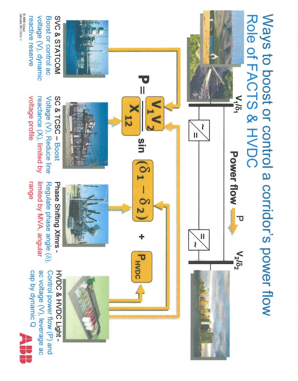
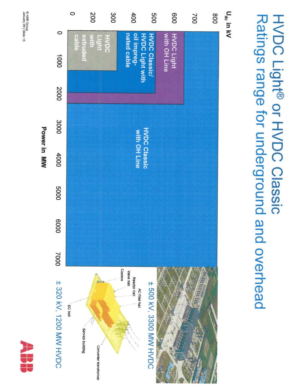
4 ABB Response August 20, 2009 HVDC Light Extruded Polymer Cables: Extruded HVDC Light cables with polymer insulation are available for both land and sea applications. These cables are much more conducive for land cable applications since they can be more easily transported on cable drums and can be spliced using pre-molded cable joints. HVDC Light land cables are currently available in voltages up to 400 kv dc. HVDC Light sea cables are currently available in voltages up to 320 kv dc. More information on ABB high voltage cables, including reference lists, can be found at HVDC Converter Technology: ABB offers conventional HVDC converter technology with line-commutated, thyristor valves and HVDC Light converter technology with self-commutated, IGBT valves. Conventional HVDC converters are available at voltages up to 800 kv and continuous current ratings up to 4000 A dc. HVDC Light converters are currently available at voltages up to +/- 320 kv and continuous current ratings of up to 1880 A dc. HVDC Light can be used for overhead transmission voltages up to +/- 640 kv for bipolar power ratings up to 2400 MW. More information on ABB HVDC technology, including reference lists, can be found at FACTS: The ABB FACTS portfolio includes series compensation, thyristor-controlled series compensation (TCSC), static var compensator (SVC) and static synchronous compensators (STATCOM). More information on ABB FACTS technologies, including reference lists, can be found at HVDC Budgetary Prices: Over the last several years, ABB has provided various budgetary EPC price estimates for HVDC and HVDC Light converter stations and cables to several different Alberta Transmission Facilities Owners (TFOs), either directly or via their consulting firms. The TFO s have added other owner costs, e.g. land, permitting, transmission lines, interconnection costs, overheads, profits, and taxes to develop their total project cost estimates. We ordinarily only provide detailed budgetary estimates to potential customers. EPC estimates by themselves may be misleading since they are not total project costs. 4
5 ABB Response August 20, 2009 HVDC Reference Lists: Links for downloading the latest available HVDC and HVDC Light Project Reference Lists can be found in the lower right-hand column at: HVDC Projects Underway: A list of HVDC and HVDC Light projects currently underway can be found in the righthand column at: FACTS Projects Reference Lists: Links to FACTS projects for series and shunt compensation respectively can be found by way of the following link: Future Offerings: The trend toward higher voltage and power ratings for conventional HVDC, HVDC Light and extruded AC and HVDC cables will continue. HVDC Light conversion efficiencies will also continue to improve. In the near future HVDC Light can be used for underground transmission at voltages up to +/- 400 kv dc and power levels up to 1500 MW per circuit. 5

6 Paper title: The ABCs of HVDC Transmission Technology Copyright 2007 IEEE. Published in: IEEE Power & Energy Magazine March/April 2007 Vol. 5 No. 2 This material is posted here with permission of the IEEE. Such permission of the IEEE does not in any way imply IEEE endorsement of any of ABB Power Technologies AB s products or services. Internal or personal use of this material is permitted. However, permission to reprint/republish this material for advertising or promotional purposes or for creating new collective works for resale or redistribution must be obtained from the IEEE by writing to pubs-permissions@ieee.org. By choosing to view this document, you agree to all provisions of the copyright laws protecting it.

7 32 IEEE power & energy magazine /07/$ IEEE march/april 2007

8 HHIGH VOLTAGE DIRECT CURRENT (HVDC) TECHNOLOGY HAS characteristics that make it especially attractive for certain transmission applications. HVDC transmission is widely recognized as being advantageous for long-distance bulk-power delivery, asynchronous interconnections, and long submarine cable crossings. The number of HVDC projects committed or under consideration globally has increased in recent years reflecting a renewed interest in this mature technology. New converter designs have broadened the potential range of HVDC transmission to include applications for underground, offshore, economic replacement of reliability-must-run generation, and voltage stabilization. This broader range of applications has contributed to the recent growth of HVDC transmission. There are approximately ten new HVDC projects under construction or active consideration in North America along with many more projects underway globally. Figure 1 shows the Danish terminal for Skagerrak s pole 3, which is rated 440 MW. Figure 2 shows the ±500-kV HVDC transmission line for the 2,000 MW Intermountain Power Project between Utah and California. This article discusses HVDC technologies, application areas where HVDC is favorable compared to ac transmission, system configuration, station design, and operating principles. Core HVDC Technologies Two basic converter technologies are used in modern HVDC transmission systems. These are conventional line-commutated current source converters (CSCs) and self-commutated voltage source converters (VSCs). Figure 3 shows a conventional HVDC converter station with CSCs while Figure 4 shows a HVDC converter station with VSCs. PHOTODISC Line-Commutated Current Source Converter Conventional HVDC transmission employs line-commutated CSCs with thyristor valves. Such converters require a synchronous voltage source in order to operate. The basic building block used for HVDC conversion is the threephase, full-wave bridge referred to as a six-pulse or Graetz bridge. The term six-pulse is due to six commutations or switching operations per period resulting in a characteristic harmonic ripple of six times the fundamental frequency in the dc output voltage. Each six-pulse bridge is comprised of six controlled switching elements or thyristor valves. Each valve is comprised of a suitable number of series-connected thyristors to achieve the desired dc voltage rating. The dc terminals of two six-pulse bridges with ac voltage sources phase displaced by 30 can be connected in series to increase the dc voltage and eliminate some of the characteristic ac current and dc voltage harmonics. Operation in this manner is referred to as 12-pulse operation. In 12-pulse operation, the characteristic ac current and dc voltage harmonics have frequencies of 12n ± 1 and 12n, respectively. The 30 phase displacement is achieved by feeding one bridge through a transformer with a wye-connected secondary and the other bridge through a transformer with a delta-connected secondary. Most modern HVDC transmission schemes utilize 12-pulse converters to reduce the harmonic filtering requirements required for six-pulse operation; e.g., fifth and seventh on the ac side and sixth on the dc side. This is because, although these harmonic currents still flow through the valves and the transformer windings, they are march/april 2007 IEEE power & energy magazine 33


9 figure 1. HVDC converter station with ac filters in the foreground and valve hall in the background. figure 2. A ±500-kV HVDC transmission line. HVDC-CSC ac ac Filters Outdoor Indoor Converter Transformers figure 3. Conventional HVDC with current source converters. 180 out of phase and cancel out on the primary side of the converter transformer. Figure 5 shows the thyristor valve arrangement for a 12-pulse converter with three quadruple valves, one for each phase. Each thyristor valve is built up with series-connected thyristor modules. Line-commutated converters require a relatively strong synchronous voltage source in order to commutate. Commutation is the transfer of current from one phase to another in a synchronized firing sequence of the thyristor valves. The three-phase symmetrical short circuit capacity available from the network at the converter connection point should be at least twice the converter rating for converter operation. Linecommutated CSCs can only operate with the ac current lagging the voltage, so the conversion process demands reactive power. Reactive power is supplied from the ac filters, which look capacitive at the fundamental frequency, shunt banks, or series capacitors that are an integral part of the converter station. Any surplus or deficit in reactive power from these local sources must be accommodated by the ac system. This difference in reactive power needs to be kept within a given band to keep the ac voltage within the desired tolerance. The weaker the ac system or the further the converter is away from generation, the tighter the reactive power exchange must be to stay within the desired voltage tolerance. Figure 6 illustrates the reactive power demand, reactive power compensation, and reactive power exchange with the ac network as a function of dc load current. Converters with series capacitors connected between the valves and the transformers were introduced in the late 1990s for weak-system, back-to-back applications. These converters are referred to as capacitor-commutated converters (CCCs). The series capacitor provides some of the converter reactive power compensation requirements automatically with load current and provides part of the commutation voltage, improving voltage stability. The overvoltage protection of the series capacitors is simple since the capacitor is not exposed to line faults, and the fault current for internal converter faults is limited by the impedance of the converter transformers. The CCC configuration allows higher power ratings in areas were the ac network is close to its voltage stability limit. The asynchronous Garabi interconnection between Brazil and Argentina consists of MW parallel CCC links. The Rapid City Tie between the Eastern and Western interconnected systems consists of MW parallel CCC links (Figure 7). Both installations use a modular design with converter valves located within prefabricated electrical enclosures rather than a conventional valve hall. dc Filters Self-Commutated Voltage Source Converter HVDC transmission using VSCs with pulse-width modulation (PWM), commercially known as HVDC Light, was introduced in the late 1990s. Since then the progression to higher voltage and power ratings for these converters has roughly paralleled that for thyristor valve converters in the 1970s. These VSC-based systems are self- 34 IEEE power & energy magazine march/april 2007 dc Thyristor Valves


10 commutated with insulated-gate bipolar transistor (IGBT) valves and solid-dielectric extruded HVDC cables. Figure 8 illustrates solid-state converter development for the two different types of converter technologies using thyristor valves and IGBT valves. HVDC transmission with VSCs can be beneficial to overall system performance. VSC technology can rapidly control both active and reactive power independently of one another. Reactive power can also be controlled at each terminal independent of the dc transmission voltage level. This control capability gives total flexibility to place converters anywhere in the ac network since there is no restriction on minimum network short-circuit capacity. Self-commutation with VSC even permits black start; i.e., the converter can be used to synthesize a balanced set of three phase voltages like a virtual synchronous generator. The dynamic support of the ac voltage at each converter terminal improves the voltage stability and can increase the transfer capability of the sending- and receiving-end ac systems, thereby leveraging the transfer capability of the dc link. Figure 9 shows the IGBT converter valve arrangement for a VSC station. Figure 10 shows the active and reactive power operating range for a converter station with a VSC. Unlike conventional HVDC transmission, the converters themselves have no reactive power demand and can actually control their reactive power to regulate ac system voltage just like a generator. HVDC Applications HVDC transmission applications can be broken down into different basic categories. Although the rationale for selection of HVDC is often economic, there may be other reasons for its selection. HVDC may be the only feasible way to interconnect two asynchronous networks, reduce fault currents, utilize long underground cable circuits, bypass network congestion, share utility rightsof-way without degradation of reliability, and to mitigate environmental concerns. In all of these applications, HVDC nicely complements the ac transmission system. HVDC-VSC ac Outdoor Indoor such as hydroelectric developments, mine-mouth power plants, or large-scale wind farms. Higher power transfers are possible over longer distances using fewer lines with HVDC transmission than with ac transmission. Typical HVDC lines utilize a bipolar configuration with two independent poles, one at a positive voltage and the other at a negative voltage with respect to ground. Bipolar HVDC lines are comparable to a double circuit ac line since they can operate at half power with one pole out of service but require only one-third the number of insulated sets of conductors as a double circuit ac line. Automatic restarts from temporary dc line fault clearing sequences are routine even for generator outlet transmission. No synchro-checking is required as for automatic reclosures following ac line faults since the dc restarts do not expose turbine generator units to high risk of transient torque amplification from closing into faults or across high phase angles. The controllability of HVDC links offer firm transmission capacity figure 4. HVDC with voltage source converters. dc IGBT Valves Thyristor Module Long-Distance Bulk Power Transmission HVDC transmission systems often provide a more economical alternative to ac transmission for long-distance bulkpower delivery from remote resources march/april 2007 Single Double Valve Quadruple Valve Thyristors figure 5. Thyristor valve arrangement for a 12-pulse converter with three quadruple valves, one for each phase. IEEE power & energy magazine 35

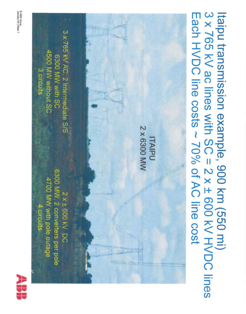
11 Shunt Banks Harmonic Filters Classic Filter figure 6. Reactive power compensation for conventional HVDC converter station. without limitation due to network congestion or loop flow on parallel paths. Controllability allows the HVDC to leap-frog multiple choke-points or bypass sequential path limits in the ac network. Therefore, the utilization of HVDC links is usually higher than that for extra high voltage ac transmission, lowering the transmission cost per MWh. This controllability can also be very beneficial for the parallel transmission since, by eliminating loop flow, it frees up this transmission capacity for its intended purpose of serving intermediate load and providing an outlet for local generation. Whenever long-distance transmission is discussed, the concept of break-even distance frequently arises. This is where the savings in line costs offset the higher converter station costs. A bipolar HVDC line uses only two insulated sets of conductors rather than three. This results in narrower rights-of-way, smaller transmission towers, and lower line losses than with ac lines of comparable capacity. A rough approximation of the savings in line construction is 30%. Although break-even distance is influenced by the costs of right-of-way and line construction with a typical value of 500 km, the concept itself is misleading because in many cases more ac lines are needed to deliver the same power over the same distance due to system stability limitations. Q 0,5 0,13 Unbalance Converter 1.0 l d Furthermore, the long-distance ac lines usually require intermediate switching stations and reactive power compensation. This can increase the substation costs for ac transmission to the point where it is comparable to that for HVDC transmission. For example, the generator outlet transmission alternative for the ±250-kV, 500- MW Square Butte Project was two 345-kV series-compensated ac transmission lines. The 12,600-MW Itaipu project has half its power delivered on three 800-kV seriescompensated ac lines (three circuits) and the other half delivered on two ±600-kV bipolar HVDC lines (four circuits). Similarly, the ±500-kV, 1,600- MW Intermountain Power Project (IPP) ac alternative comprised two 500-kV ac lines. The IPP takes advantage of the double-circuit nature of the bipolar line and includes a 100% short-term and 50% continuous monopolar overload. The first 6,000-MW stage of the transmission for the Three Gorges Project in China would have required kV ac lines as opposed to 2 ±500-kV, 3,000-MW bipolar HVDC lines. Table 1 contains an economic comparison of capital costs and losses for different ac and dc transmission alternatives for a hypothetical 750-mile, 3,000-MW transmission system. The long transmission distance requires intermediate substations or switching stations and shunt reactors for the ac alternatives. The long distance and heavy power transfer, nearly twice the surge-impedance loading on the 500-kV ac alternatives, require a high level of series compensation. These ac station costs are included in the cost estimates for the ac alternatives. It is interesting to compare the economics for transmission to that of transporting an equivalent amount of energy using other transport methods, in this case using rail transportation of sub-bituminous western coal with a heat content of 8,500 Btu/lb to support a 3,000-MW base load power plant with heat rate of 8,500 Btu/kWh operating at an 85% l d Ua ++ Ula Uca + l a Ub ++ Ulb Ucb + l b Uc ++ Ulc Ucc + l c Valve Enclosures Commutation Capacitor Converter Transformer figure 7. Asynchronous back-to-back tie with capacitor-commutated converter near Rapid City, South Dakota. 36 IEEE power & energy magazine march/april 2007

12 load factor. The rail route is assumed to be longer than the more direct transmission route; i.e., 900 miles. Each unit train is comprised of 100 cars each carrying 100 tons of coal. The plant requires three unit trains per day. The annual coal transportation costs are about US$560 million per year at an assumed rate of US$50/ton. This works out to be US$186 kw/year and US$25 per MWh. The annual diesel fuel consumed in the process is in excess of 20 million gallons at 500 net ton-miles per gallon. The rail transportation costs are subject to escalation and congestion whereas the transmission costs are fixed. Furthermore, transmission is the only way to deliver remote renewable resources. 2,000 1,800 1,600 1,400 1,200 1, Underground and Submarine Cable Transmission Unlike the case for ac cables, there is no physical restriction limiting the distance or power level for HVDC underground or submarine cables. Underground cables can be used on shared rights-ofway with other utilities without impacting reliability concerns over use of common corridors. For underground or submarine cable systems there is considerable savings in installed cable costs and cost of losses when using HVDC transmission. Depending on the power level to be transmitted, these savings can offset the higher converter station costs at distances of 40 km or more. Furthermore, there is a drop-off in cable capacity with ac transmission over distance due to its reactive component of charging current since cables have higher capacitances and lower inductances than ac overhead lines. Although this can be compensated by intermediate shunt compensation for underground cables at increased expense, it is not practical to do so for submarine cables. For a given cable conductor area, the line losses with HVDC cables can be about half those of ac cables. This is due to ac cables requiring more conductors (three phases), carrying the reactive component of current, skin-effect, and induced currents in the cable sheath and armor. With a cable system, the need to balance unequal loadings or the risk of postcontingency overloads often necessitates use of a series-connected reactors or phase shifting transformers. These potential problems do not exist with a controlled HVDC cable system. Extruded HVDC cables with prefabricated joints used with VSC-based transmission are lighter, more flexible, and easier to splice than the mass-impregnated oil-paper cables figure 8. Solid-state converter development Thyristor MW Thyristor KV IGBT MW IGBT kv IGBT Valve StakPak figure 9. HVDC IGBT valve converter arrangement. Submodule Cable Chip (MINDs) used for conventional HVDC transmission, thus making them more conducive for land cable applications where transport limitations and extra splicing costs can drive up installation costs. The lower-cost cable installations made possible by the extruded HVDC cables and prefabricated joints makes long-distance underground transmission economically feasible for use in areas with rights-of-way constraints or subject to permitting difficulties or delays with overhead lines. Asynchronous Ties With HVDC transmission systems, interconnections can be made between asynchronous networks for more economic or reliable system operation. The asynchronous interconnection allows interconnections of mutual benefit while providing a buffer between the two systems. Often these interconnections use back-to-back converters with no transmission line. march/april 2007 IEEE power & energy magazine 37
 and its neigh")
13 Asynchronous HVDC links act as an effective firewall against propagation of cascading outages in one network from passing to another network. Many asynchronous interconnections exist in North America between the Eastern and Western interconnected systems, between the Electric Reliability Council of Texas (ERCOT) and its neighbors, [e.g., Mexico and the Southwest Power Pool (SPP)], and between Quebec and its neighbors (e.g., New England and the Maritimes). The August 2003 Active Power (p.u.) P-Q Diagram Reactive Power (p.u.) HVDC VSC Operating Range figure 10. Operating range for voltage source converter HVDC transmission x 40 MW VSC HVDC figure 11. VSC power supply to Troll A production platform. Northeast blackout provides an example of the firewall against cascading outages provided by asynchronous interconnections. As the outage expanded and propagated around the lower Great Lakes and through Ontario and New York, it stopped at the asynchronous interface with Quebec. Quebec was unaffected; the weak ac interconnections between New York and New England tripped, but the HVDC links from Quebec continued to deliver power to New England. Regulators try to eliminate seams in electrical networks because of their potential restriction on power markets. Electrical seams, however, serve as natural points of separation by acting as shear-pins, thereby reducing the impact of large-scale system disturbances. Asynchronous ties can eliminate market seams while retaining natural points of separation. Interconnections between asynchronous networks are often at the periphery of the respective systems where the networks tend to be weak relative to the desired power transfer. Higher power transfers can be achieved with improved voltage stability in weak system applications using CCCs. The dynamic voltage support and improved voltage stability offered by VSC-based converters permits even higher power transfers without as much need for ac system reinforcement. VSCs do not suffer commutation failures, allowing fast recoveries from nearby ac faults. Economic power schedules that reverse power direction can be made without any restrictions since there is no minimum power or current restrictions. Operating Area Offshore Transmission Self-commutation, dynamic voltage control, and black-start capability allow compact VSC HVDC transmission to serve isolated loads on islands or offshore production platforms over long-distance submarine cables. This capability can eliminate the need for running expensive local generation or provide an outlet for offshore generation such as that from wind. The VSCs can operate at variable frequency to more efficiently drive large compressor or pumping loads using high-voltage motors. Figure 11 shows the Troll A production platform in the North Sea where power to drive compressors is delivered from shore to reduce the higher carbon emissions and higher O&M costs associated with less efficient platform-based generation. Large remote wind generation arrays require a collector system, reactive power 38 IEEE power & energy magazine march/april 2007
14 support, and outlet transmission. Transmission for wind generation must often traverse scenic or environmentally sensitive areas or bodies of water. Many of the better wind sites with higher capacity factors are located offshore. VSC-based HVDC transmission allows efficient use of long-distance land or submarine cables and provides reactive support to the wind generation complex. Figure 12 shows a design for an offshore converter station designed to transmit power from offshore wind generation. Multiterminal Systems Most HVDC systems are for point-to-point transmission with a converter station at each end. The use of intermediate taps is rare. Conventional HVDC transmission uses voltage polarity reversal to reverse the power direction. Polarity reversal requires no special switching arrangement for a twoterminal system where both terminals reverse polarity by control action with no switching to reverse power direction. Special dc-side switching arrangements are needed for polarity reversal in a multiterminal system, however, where it may be desired to reverse the power direction at a tap while maintaining the same power direction on the remaining terminals. For a bipolar system this can be done by connecting the converter to the opposite pole. VSC HVDC transmission, however, reverses power through reversal of the current direction rather than voltage polarity. Thus, power can be reversed at an intermediate tap independently of the main power flow direction without switching to reverse voltage polarity. Power Delivery to Large Urban Areas Power supply for large cities depends on local generation and power import capability. Local table 1. Comparative costs of HVDC and EHV AC transmission alternatives. DC Alternatives AC Alternatives Hybrid AC/DC Alternative Alternative Kv 2 x kv kv +800 kv 500 kv 500 kv 765 kv kv 500 kv Total Bipole 2 bipoles Bipole Bipole 2 Single Ckt Double Ckt 2 Singl Ckt Bipole Single Ckt AC + DC Capital Cost Rated Power (MW) Station costs including reactive compenstation (M$) $420 $680 $465 $510 $542 $542 $630 $420 $302 $722 Transmission line cost (M$/mile) $1.60 $1.60 $1.80 $1.95 $2.00 $3.20 $2.80 $1.60 $2.00 Distance in miles 750 1, , , ,500 Transmission Line Cost (M$) $1,200 $2,400 $1,350 $1,463 $3,000 $2,400 $4,200 $1,200 $1,500 $2,700 Total Cost (M$) $1,620 $3,080 $1,815 $1,973 $3,542 $2,942 $4,830 $1,620 $1,802 $3,422 Annual Payment, 30 10% $172 $327 $193 $209 $376 $312 $512 $172 $191 $363 Cost per kw-yr $57.28 $81.68 $64.18 $69.75 $ $ $ $57.28 $ $80.66 Cost per 85% Utilization Factor $7.69 $10.97 $8.62 $9.37 $16.82 $13.97 $22.93 $7.69 $17.11 $10.83 full load Losses at full load in % 6.44% 3.35% 4.93% 3.43% 6.93% 6.93% 4.62% 5.29% 4.79% 5.12% Capitalized cost of $1500 kw (M$) $246 $171 $188 $131 $265 $265 $177 $135 $61 $196 Parameters: Interest rate % 10% Capitalized cost of losses $/kw $1,500 Note: AC current assumes 94% pf Full load converter station losses = 9.75% per station Total substation losses (transformers, reactors) assumed = 0.5% of rated power march/april 2007 IEEE power & energy magazine 39

15 generation is often older and less efficient than newer units located remotely. Often, however, the older, less-efficient units located near the city center must be dispatched out-ofmerit because they must be run for voltage support or reliability due to inadequate transmission. Air quality regulations may limit the availability of these units. New transmission into large cities is difficult to site due to right-of-way limitations and land-use constraints. figure 12. VSC converter for offshore wind generation. Compact VSC-based underground transmission circuits can be placed on existing dual-use rights-of-way to bring in power as well as to provide voltage support, allowing a more economical power supply without compromising reliability. The receiving terminal acts like a virtual generator delivering power and supplying voltage regulation and dynamic reactive power reserve. Stations are compact and housed mainly indoors, making siting in urban areas somewhat easier. Furthermore, the dynamic voltage support offered by the VSC can often increase the capability of the adjacent ac transmission. System Configurations and Operating Modes Figure 13 shows the different common system configurations and operating modes used for HVDC transmission. Monopolar systems are the simplest and least expensive systems for moderate power transfers since only two converters and one high-voltage insulated cable or line conductor are required. Such systems have been used with low-voltage electrode lines and sea electrodes to carry the return current in submarine cable crossings. In some areas conditions are not conducive to monopolar earth or sea return. This could be the case in heavily congested Monopole, Ground Return Bipole Bipole, Series-Connected Converters Monopole, Metallic Return Monopole, Midpoint Grounded Bipole, Metallic Return Back-to-Back Multiterminal figure 13. HVDC configurations and operating modes. 40 IEEE power & energy magazine march/april 2007


16 ac Switchyard Converter Transformers ac Line Valve Hall Shunt Capacitors dc Line Harmonic Filters dc Switchyard figure 14. Monopolar HVDC converter station. areas, fresh water cable crossings, or areas with high earth resistivity. In such cases a metallic neutral- or low-voltage cable is used for the return path and the dc circuit uses a simple local ground connection for potential reference only. Back-toback stations are used for interconnection of asynchronous networks and use ac lines to connect on either side. In such systems power transfer is limited by the relative capacities of the adjacent ac systems at the point of connection. As an economic alternative to a monopolar system with metallic return, the midpoint of a 12-pulse converter can be connected to earth directly or through an impedance and two half-voltage cables or line conductors can be used. The converter is only operated in 12-pulse mode so there is never any stray earth current. VSC-based HVDC transmission is usually arranged with a single converter connected pole-to-pole rather than poleto-ground. The center point of the converter is connected to ground through a high impedance to provide a reference for the dc voltage. Thus, half the converter dc voltage appears across the insulation on each of the two dc cables, one positive the other negative. The most common configuration for modern overhead HVDC transmission lines is bipolar with a single 12-pulse converter for each pole at each terminal. This gives two independent dc circuits each capable of half capacity. For normal balanced operation there is no earth current. Monopolar earth return operation, often with overload capacity, can be used during outages of the opposite pole. Earth return operation can be minimized during monopolar outages by using the opposite pole line for metallic return via pole/converter bypass switches at each end. This requires a metallic-return transfer breaker in the ground electrode line at Coolers ac Filters figure 15. VSC HVDC converter station. Phase Reactors IGBT Valve Enclosures march/april 2007 IEEE power & energy magazine 41
17 one of the dc terminals to commutate the current from the relatively low resistance of the earth into that of the dc line conductor. Metallic return operation capability is provided for most dc transmission systems. This not only is effective during converter outages but also during line insulation failures where the remaining insulation strength is adequate to withstand the low resistive voltage drop in the metallic return path. For very-high-power HVDC transmission, especially at dc voltages above ±500 kv (i.e., ±600 kv or ±800 kv), seriesconnected converters can be used to reduce the energy unavailability for individual converter outages or partial line insulation failure. By using two series-connected converters per pole in a bipolar system, only one quarter of the transmission capacity is lost for a converter outage or if the line insulation for the affected pole is degraded to where it can only support half the rated dc line voltage. Operating in this mode also avoids the need to transfer to monopolar metallic return to limit the duration of emergency earth return. Station Design and Layout Conventional HVDC The converter station layout depends on a number of factors such as the dc system configuration (i.e., monopolar, bipolar, or back-to-back), ac filtering, and reactive power compensation requirements. The thyristor valves are air-insulated, water-cooled, and enclosed in a converter building often referred to as a valve hall. For back-to-back ties with their characteristically low dc voltage, thyristor valves can be housed in prefabricated electrical enclosures, in which case a valve hall is not required. To obtain a more compact station design and reduce the number of insulated high-voltage wall bushings, converter transformers are often placed adjacent to the valve hall with valve winding bushings protruding through the building walls for connection to the valves. Double or quadruple valve structures housing valve modules are used within the valve hall. Valve arresters are located immediately adjacent to the valves. Indoor motor-operated grounding switches are used for personnel safety during maintenance. Closed-loop valve cooling systems are used to circulate the cooling medium, deionized water or water-glycol mix, through the indoor thyristor valves with heat transfer to dry coolers located outdoors. Area requirements for conventional HVDC converter stations are influenced by the ac system voltage and reactive power compensation requirements where each individual bank rating may be limited by such system requirements as reactive power exchange and maximum voltage step on bank switching. The ac yard with filters and shunt compensation can take up as much as three quarters of the total area requirements of the converter station. Figure 14 shows a typical arrangement for an HVDC converter station. VSC-Based HVDC The transmission circuit consists of a bipolar two-wire HVDC system with converters connected pole-to-pole. DC capacitors are used to provide a stiff dc voltage source. The dc capacitors are grounded at their electrical center point to establish the earth reference potential for the transmission system. There is no earth return operation. The converters are coupled to the ac system through ac phase reactors and power transformers. Unlike most conventional HVDC systems, harmonic filters are located between the phase reactors and power transformers. Therefore, the transformers are exposed to no dc voltage stresses or harmonic loading, allowing use of ordinary power transformers. Figure 15 shows the station arrangement for a ±150-kV, 350 to 550-MW VSC converter station. The IGBT valves used in VSC converters are comprised of series-connected IGBT positions. The IGBT is a hybrid device exhibiting the low forward drop of a bipolar transistor as a ac Bus Control TCP ID dc Line R Control TCP ac Bus UdR Udl I R I S u α I T I u R R us I S u IT T I d U d u T u R α u u S figure 16. Conventional HVDC control. 42 IEEE power & energy magazine march/april 2007
18 conducting device. Instead of the regular current-controlled base, the IGBT has a voltage-controlled capacitive gate, as in the MOSFET device. A complete IGBT position consists of an IGBT, an antiparallel diode, a gate unit, a voltage divider, and a watercooled heat sink. Each gate unit includes gate-driving circuits, surveillance circuits, and optical interface. The gatedriving electronics control the gate voltage and current at turn-on and turn-off to achieve optimal turn-on and turn-off processes of the IGBTs. To be able to switch voltages higher than the rated voltage of one IGBT, many positions are connected in series in each valve similar to thyristors in conventional HVDC valves. All IGBTs must turn on and off at the same moment to achieve an evenly distributed voltage across the valve. Higher currents are handled by paralleling IGBT components or press packs. The primary objective of the valve dc-side capacitor is to provide a stiff voltage source and a low-inductance path for the turn-off switching currents and to provide energy storage. The capacitor also reduces the harmonic ripple on the dc voltage. Disturbances in the system (e.g., ac faults) will cause dc voltage variations. The ability to limit these voltage variations depends on the size of the dc-side capacitor. Since the dc capacitors are used indoors, dry capacitors are used. AC filters for VSC HVDC converters have smaller ratings than those for conventional converters and are not required for reactive power compensation. Therefore, these filters are always connected to the converter bus and not switched with transmission loading. All equipment for VSC-based HVDC converter stations, except the transformer, high-side breaker, and valve coolers, is located indoors. HVDC Control and Operating Principles Conventional HVDC The fundamental objectives of an HVDC control system are as follows: 1) to control basic system quantities such as dc line current, dc voltage, and transmitted power accurately and with sufficient speed of response 2) to maintain adequate commutation margin in inverter operation so that the valves can recover their forward blocking capability after conduction before their voltage polarity reverses 3) to control higher-level quantities such as frequency in isolated mode or provide power oscillation damping to help stabilize the ac network 4) to compensate for loss of a pole, a generator, or an ac transmission circuit by rapid readjustment of power 5) to ensure stable operation with reliable commutation in the presence of system disturbances 6) to minimize system losses and converter reactive power consumption 7) to ensure proper operation with fast and stable recoveries during ac system faults and disturbances. ac Line Voltages OPWM u DC1 u DC2 u AC-ref1 + q ref1 u AC1 ac Voltage Control i PWM Internal Current Control u DC-ref1 + dc Voltage Control p ref1 u DC-ref2 + dc Voltage Control p ref2 PWM Internal Current Control i u AC2 u AC-ref2 ac Voltage Control q ref2 figure 17. Control of VSC HVDC transmission. Principle Control of HVDC-Light march/april 2007 IEEE power & energy magazine 43
19 For conventional HVDC transmission, one terminal sets the dc voltage level while the other terminal(s) regulates the (its) dc current by controlling its output voltage relative to that maintained by the voltage-setting terminal. Since the dc line resistance is low, large changes in current and hence power can be made with relatively small changes in firing angle (alpha). Two independent methods exist for controlling the converter dc output voltage. These are 1) by changing the ratio between the direct voltage and the ac voltage by varying the delay angle or 2) by changing the converter ac voltage via load tap changers (LTCs) on the converter transformer. Whereas the former method is rapid the latter method is slow due to the limited speed of response of the LTC. Use of high delay angles to achieve a larger dynamic range, however, increases the converter reactive power consumption. To minimize the reactive power demand while still providing adequate dynamic control range and commutation margin, the LTC is used at the rectifier terminal to keep the delay angle within its desired steady-state range (e.g., ) and at the inverter to keep the extinction angle within its desired range (e.g., ), if the angle is used for dc voltage control or to maintain rated dc voltage if operating in minimum commutation margin control mode. Figure 16 shows the characteristic transformer current and dc bridge voltage waveforms along with the controlled items Ud, Id, and tap changer position (TCP). VSC-Based HVDC Power can be controlled by changing the phase angle of the converter ac voltage with respect to the filter bus voltage, whereas the reactive power can be controlled by changing the magnitude of the fundamental component of the converter ac voltage with respect to the filter bus voltage. By controlling these two aspects of the converter voltage, operation in all four quadrants is possible. This means that the converter can be operated in the middle of its reactive power range near unity power factor to maintain dynamic reactive power reserve for contingency voltage support similar to a static var compensator. It also means that the real power transfer can be changed rapidly without altering the reactive power exchange with the ac network or waiting for switching of shunt compensation. Being able to independently control ac voltage magnitude and phase relative to the system voltage allows use of separate active and reactive power control loops for HVDC system regulation. The active power control loop can be set to control either the active power or the dc-side voltage. In a dc link, one station will then be selected to control the active power while the other must be set to control the dc-side voltage. The reactive power control loop can be set to control either the reactive power or the ac-side voltage. Either of these two modes can be selected independently at either end of the dc link. Figure 17 shows the characteristic ac voltage waveforms before and after the ac filters along with the controlled items Ud, Id, Q, and Uac. Conclusions The favorable economics of long-distance bulk-power transmission with HVDC together with its controllability make it an interesting alternative or complement to ac transmission. The higher voltage levels, mature technology, and new converter designs have significantly increased the interest in HVDC transmission and expanded the range of applications. For Further Reading B. Jacobson, Y. Jiang-Hafner, P. Rey, and G. Asplund, HVDC with voltage source converters and extruded cables for up to ±300 kv and 1000 MW, in Proc. CIGRÉ 2006, Paris, France, pp. B L. Ronstrom, B.D. Railing, J.J. Miller, P. Steckley, G. Moreau, P. Bard, and J. Lindberg, Cross sound cable project second generation VSC technology for HVDC, Proc. CIGRÉ 2006, Paris, France, pp. B M. Bahrman, D. Dickinson, P. Fisher, and M. Stoltz, The Rapid City Tie New technology tames the East-West interconnection, in Proc. Minnesota Power Systems Conf., St. Paul, MN, Nov D. McCallum, G. Moreau, J. Primeau, D. Soulier, M. Bahrman, and B. Ekehov, Multiterminal integration of the Nicolet Converter Station into the Quebec-New England Phase II transmission system, in Proc. CIGRÉ 1994, Paris, France. A. Ekstrom and G. Liss, A refined HVDC control system, IEEE Trans. Power Systems, vol. PAS-89, pp , May-June Biographies Michael P. Bahrman received a B.S.E.E. from Michigan Technological University. He is currently the U.S. HVDC marketing and sales manger for ABB Inc. He has 24 years of experience with ABB Power Systems including system analysis, system design, multiterminal HVDC control development, and project management for various HVDC and FACTS projects in North America. Prior to joining ABB, he was with Minnesota Power for 10 years where he held positions as transmission planning engineer, HVDC control engineer, and manager of system operations. He has been an active member of IEEE, serving on a number of subcommittees and working groups in the area of HVDC and FACTS. Brian K. Johnson received the Ph.D. in electrical engineering from the University of Wisconsin-Madison. He is currently a professor in the Department of Electrical and Computer Engineering at the University of Idaho. His interests include power system protection and the application of power electronics to utility systems, security and survivability of ITS systems and power systems, distributed sensor and control networks, and real-time simulation of traffic systems. He is a member of the Board of Governors of the IEEE Intelligent Transportation Systems Society and the Administrative Committee of the IEEE Council on Superconductivity. p&e 44 IEEE power & energy magazine march/april 2007

20
21
22

23

24
25
26
27
28
29

30
31

32
33
34

35

36

37
38
39
40

41

42
43

44

45
46

47

48

49
50

51

52
53

54

55

56

57
58
59
60
61
62
63
64
65
66
67
68
69
70
71

72

73
74
75

76

77

78

79 HVDC & SVC Light - Reference list
80 ABB HVDC & SVC Light Projects Worldwide Hällsjön 2 Hagfors 3 Gotland 4 Directlink 5 Tjæreborg 6 Eagle Pass 7 Moselstahlwerke 8 Cross Sound Cable 9 Murraylink 10 Polarit 11 Evron 12 Troll A 13 Holly 14 Estlink 15 Ameristeel 16 ZPSS 17 Mesnay 18 Martham 19 Liepajas 20 Siam Yamato 21 NORD E.ON 1 22 Caprivi Link Interconnector 23 Valhall 6 13

81
82 SCHEME 1. HÄLLSJÖN HVDC Light 2. HAGFORS SVC Light 3. GOTLAND HVDC Light Commissioning year Power Transmitted, MW 3-50 Direct voltage, kv ±10 - ±80 Converters per station Direct voltage per converter, kv ±10 - ±80 Direct current, A Reactive power range, MVAr ± /-55 Converter station location and AC grid voltage Hällsjön, 10 kv, 50 Hz Grängesberg, 10 kv, 50 Hz Hagfors, 36 kv, 50 Hz Näs, 77 kv, 50 Hz Bäcks, 77 kv, 50 Hz Length of overhead DC line, km Cable arrangement - - Bipolar Length of cable route, km Grounding of the DC circuit AC grids at both ends Synchronous - Synchronous Control Active and reactive power Steel, reactive power, flicker mitigation Active and reactive power, AC voltage Emergency change of power flow Main reason for choosing VSC system Pilot system Flicker mitigation Wind power, environmental, controllability Owner VB Elnät, SWEDEN Uddeholm, SWEDEN GEAB, SWEDEN Main supplier of converter equipment ABB ABB ABB
83 4. DIRECTLINK HVDC Light 5. TJÆREBORG HVDC Light 6. EAGLE PASS HVDC Light 7. MOSELSTAHLWERKE SVC Light x ±80 ± ±80 ± /-165-3/+4 ± Terranora, 110 kv, 50 Hz Mullumbimby, 132 kv, 50 Hz Enge, 10.5 kv, 50 hz Tjæreborg, 10.5 kv, 50 Hz Eagle Pass, 138 kv, 60 Hz Trier, 20 kv, 50 Hz Bipolar Bipolar (Back to Back) Asynchronous (when delivered) Synchronous / asynchronous Asynchronous - Active and reactive power, AC voltage Active and reactive power, AC voltage, variable frequency control Active and reactive power, AC voltage Steel, reactive power, flicker mitigation - - Runback implemented - Energy trade, environment, controllability Wind power, environment, controllability AC voltage support (SVC operation), power exchange Flicker mitigation TransEnergy, USA North Power, AUSTRALIA Eltra, DENMARK AEP, USA RWE Energie, GERMANY ABB ABB ABB ABB
84 SCHEME 8. CROSS SOUND CABLE HVDC Light 9. MURRAYLINK HVDC Light 10. POLARIT SVC Light Commissioning year Power Transmitted, MW Direct voltage, kv ±150 ±150 - Converters per station Direct voltage per converter, kv ±150 ±150 - Direct current, A Reactive power range, MVAr ± / Converter station location and AC grid voltage New Haven, 345 kv, 60 Hz Shoreham, 138 kv, 60 Hz Berri, 132 kv Red Cliffs, 220 kv Tornio, 33 kv, 50 Hz Length of overhead DC line, km Cable arrangement Bipolar Bipolar - Length of cable route, km Grounding of the DC circuit AC grids at both ends Synchronous Synchronous - Control Active and reactive power, AC voltage Active power and AC voltage Steel, reactive power, flicker mitigation Emergency change of power flow Runback implemented Runback implemented - Main reason for choosing VSC system Energy trade, controllability Energy trade, environment, controllability Very high flicker mitigation, compactness Owner TransEnergie US, USA TransEnergie US, USA AvestaPolarit Stainless Oy, FINLAND Main supplier of converter equipment ABB ABB ABB
85 11. EVRON SVC Light 12. TROLL A HVDC Light 13. HOLLY SVC Light 14. ESTLINK HVDC Light 15. AMERISTEEL SVC Light x ±60 - ± ± ±17 Troll A: NA Kollsnes: +24/ / -80 ±125 ±32 Evron, 90 kv, 50 Hz Troll A, 56 kv Kollsnes, 132 kv Austin, 138 kv, 60 Hz Espoo, 400 kv, 50 Hz Harku, 330 kv, 50 Hz Charlotte, 13.2 kv, 60 Hz Bipolar - Bipolar Asynchronous - Railway, load balancing, active filtering Motordrive and VHV motor, AC voltage, frequency control Reactive power Active and reactive power, AC voltage, frequency control, damping control Steel, reactive power, flicker mitigation Runback implemented, black start - Active filtering Platform electrification, environment, CO 2 -tax Voltage support, compactness Energy trade, AC voltage contol Flicker mitigation SNCF/RTE, FRANCE Statoil, NORWAY Austin Energy, USA Nordic Energy Link AS, ESTONIA Gerdau Ameristeel, USA ABB ABB ABB ABB ABB
86 SCHEME 16. ZPSS SVC Light 17. MESNAY SVC Light 18. MARTHAM SVC Light 19. LIEPAJAS SVC Light Commissioning year Power Transmitted, MW Direct voltage, kv Converters per station Direct voltage per converter, kv Direct current, A Reactive power range, MVAr ±82 ±15 ±0.6 ±164 Converter station location and AC grid voltage Ziangjiagang, 35 kv, 50 Hz Jura Mesnay, 63 kv, 50 Hz Martham, 11 kv, 50 Hz Liepaja, 33 kv, 50 Hz Length of overhead DC line, km Cable arrangement Length of cable route, km Grounding of the DC circuit AC grids at both ends Control Steel, reactive power, flicker mitigation Railway, load balancing, active filtering Active and reactive power Steel, reactive power, flicker mitigation Emergency change of power flow Main reason for choosing VSC system Flicker mitigation Active filtering Voltage support Flicker mitigation Owner ZPSS, CHINA SNCF/RTE, FRANCE EDF Energy, UK Liepajas Metalurgs, LATVIA Main supplier of converter equipment ABB ABB ABB ABB
87 20. SIAM YAMATO SVC Light 21. NORD E.ON 1 HVDC Light 22. CAPRIVI LINK HVDC Light 23. VALHALL HVDC Light ± ± ±120 ±150 ± 200 Valhall: 110 transient Lista: +10/-10 Bangkok, 22 kv, 50 Hz Diele, 380 kv, Borkum 2, 170 kv Zambezi, 330 kv, 50 Hz Gerus, 400 kv, 50 Hz Lista, 300 kv Valhall, 11 kv Bipolar - Coaxial Earth electrode - - Asynchronous Synchronous 50 Hz, 60 Hz isolated Steel, reactive power, flicker mitigation Active and reactive power, AC voltage, frequency control - Runback implemented Active power, AC voltage, frequency control Runback implemented, power supply of black network AC voltage, frequency control - Flicker mitigation Offshore wind, power to shore Energy trade, energy import, weak AC networks Platform electrification, environment, CO 2 -tax Siam Yamato Steel, THAI- LAND E.ON Netz, GERMANY NamPower, NAMIBIA BP, NORWAY ABB ABB ABB ABB
88 POW-0027 Rev. 7 Elanders, 2007, Västerås ABB AB ABB AB Grid Systems - HVDC Grid Systems - FACTS SE Ludvika, Sweden SE Västerås, Sweden Tel: Tel Fax: Fax:

89 Elanders, Västerås 2008 HVDC Classic - Reference list Thyristor valve projects and converter station upgrades POW-0013 Rev. 7 ABB AB Grid Systems - HVDC SE Ludvika, Sweden Tel: Fax:
Gunnar Asplund HVDC R&D Manager Sweden. Latest HVDC Light developments. IEEE Montreal
 Gunnar Asplund HVDC R&D Manager Sweden Latest HVDC Light developments IEEE Montreal 2006-06-21 HVDC Light, continuous reactive power control HVDC static Q (p.u.) HVDC dynamic HVDC Light P (pu) BA PTPS
ABB Group August 27, 2010 Slide 1
 Michael Bahrman P.E., ABB Grid Systems, August 31, 2010, Asia Pacific Clean Energy Summit 2010, Honolulu Integration of Variable Renewable Energy for Hawaii Transmission of Isolated Resources August 27,
The Application of Power Electronics to the Alberta Grid
 The Application of Power Electronics to the Alberta Grid Peter Kuffel, Michael Paradis ATCO Electric APIC May 5, 2016 Power Electronics Semiconductor devices used in power transmission systems Types: Thyristor
Offshore Wind Connections HVDC for Offshore Grids
 Michael Bahrman P.E., Grid Systems, UWIG Technical Workshop, Maui, October 2011 Offshore Wind Connections HVDC for Offshore Grids October 18, 2011 Slide 1 HVDC for Offshore Grids Topics Offshore wind market
ABB POWER SYSTEMS CONSULTING
 ABB POWER SYSTEMS CONSULTING DOMINION VIRGINIA POWER Offshore Wind Interconnection Study 2011-E7406-1 R1 Summary Report Prepared for: DOMINION VIRGINIA POWER Report No.: 2011-E7406-1 R1 Date: 29 February
HVDC Solutions. for Integration of the Renewable Energy Resources. Marcus Haeusler HVDC Lead Engineer. siemens.com/energy/power-transmission
 HVDC Solutions for Integration of the Renewable Energy Resources Marcus Haeusler HVDC Lead Engineer siemens.com/energy/power-transmission Agenda Principles of HVDC operation HVDC converter types HVDC configurations
Peter Lundberg, ABB HVDC, Nov 2016 HVDC Light - Power from shore. ABB Group November 16, 2016 Slide 1 1JNL A
 Peter Lundberg, ABB HVDC, Nov 2016 HVDC Light - Power from shore November 16, 2016 Slide 1 1JNL258935 A Content Driving forces Challenges Solutions Reference projects Summary November 16, 2016 Slide 2
Dr.-Ing. Ervin Spahi, Wadden Sea Forum, Bremerhaven Electric grid on and off-shore: current status, obstacles and new developments
 Dr.-Ing. Ervin Spahi, Wadden Sea Forum, Bremerhaven 26.11.09 Electric grid on and off-shore: current status, obstacles and new developments November 26, 2009 Slide 1 Transmission grid The challenges Optimal
Evaluation of the Performance of Back-to-Back HVDC Converter and Variable Frequency Transformer for Power Flow Control in a Weak Interconnection
 Evaluation of the Performance of Back-to-Back HVDC Converter and Variable Frequency Transformer for Power Flow Control in a Weak Interconnection B. Bagen, D. Jacobson, G. Lane and H. M. Turanli Manitoba
Chapter 1. Overview of HVDC applications
 ELEC0445 - High Voltage Direct Current grids Part 1. Line Commutated Converters Chapter 1. Overview of HVDC applications Patricia Rousseaux t.vancutsem@ulg.ac.be Thierry Van Cutsem www.montefiore.ulg.ac.be/~vct
HVDC POWER FROM SHORE. B. WESTMAN* K. ERIKSSON* G. PERSSON* A. MÆLAND** ABB Sweden*, Norway**
 http://www.cigre.org B4-PS1 Planning and implementation of HVDC projects including, need, justification, design, integration of wind generation, environmental and economic assessment. 2016 Paris Session
Power Engineering - Egill Benedikt Hreinsson. Lecture 15a. HVDC Transmission. 2 November 2011
 1 HVDC Transmission 2 HVDC Transmission High Voltage Direct Current Transmission 3 AC to DC Comparison Originally the power systems were DC An historical struggle between Edison and Westinghouse was called:
Wind Power Plants with VSC Based STATCOM in PSCAD/EMTDC Environment
 2012 2nd International Conference on Power and Energy Systems (ICPES 2012) IPCSIT vol. 56 (2012) (2012) IACSIT Press, Singapore DOI: 10.7763/IPCSIT.2012.V56.2 Wind Power Plants with VSC Based STATCOM in
Overview of Flexible AC Transmission Systems
 Overview of Flexible AC Transmission Systems What is FACTS? Flexible AC Transmission System (FACTS): Alternating current transmission systems incorporating power electronic-based and other static controllers
Raphael Görner, Head of Marketing & Sales, Grid Systems Germany Building bridges with HVDC Solar Energy for Science
 Raphael Görner, Head of Marketing & Sales, Grid Systems Germany 20.05.2011 Building bridges with HVDC Solar Energy for Science May 20, 2011 Slide 1 Europe 20XX Scenario ABB s DC grid vision already in
POWER TRANSMISSION OF LOW FREQUENCY WIND FIRMS
 Available Online at www.ijcsmc.com International Journal of Computer Science and Mobile Computing A Monthly Journal of Computer Science and Information Technology IJCSMC, Vol. 3, Issue. 10, October 2014,
Protective firing in LCC HVDC: Purposes and present principles. Settings and behaviour. V. F. LESCALE* P. KARLSSON
 21, rue d Artois, F-75008 PARIS B4-70 CIGRE 2016 http : //www.cigre.org Protective firing in LCC HVDC: Purposes and present principles. Settings and behaviour. V. F. LESCALE* P. KARLSSON VILES Consulting
Benefits of HVDC and FACTS Devices Applied in Power Systems
 Benefits of HVDC and FACTS Devices Applied in Power Systems 1 P. SURESH KUMAR, 2 G. RAVI KUMAR 1 M.Tech Research Scholar, Priyadarshini Institute of Technology & Management 2 Associate Professor, Priyadarshini
ELG4125: Flexible AC Transmission Systems (FACTS)
") ELG4125: Flexible AC Transmission Systems (FACTS) The philosophy of FACTS is to use power electronics for controlling power flow in a transmission network, thus allowing the transmission line to be loaded
ELG4125: Flexible AC Transmission Systems (FACTS) The philosophy of FACTS is to use power electronics for controlling power flow in a transmission network, thus allowing the transmission line to be loaded
Next Generation of UHVDC System. R. Montaño, D Wu, L. Arevalo, B. Jacobson ABB - HVDC Sweden
 Conference-1 Latest Technologies in T & D, Renewable Energy Integration, Smart Grid, Energy Efficiency, Communication Next Generation of UHVDC System R. Montaño, D Wu, L. Arevalo, B. Jacobson ABB - HVDC
Transmission Grid Reinforcement with Embedded VSC-HVDC. Jonatan Danielsson, Sugam Patel, Jiuping Pan, Reynaldo Nuqui
 Transmission Grid Reinforcement with Embedded VSC-HVDC Jonatan Danielsson, Sugam Patel, Jiuping Pan, Reynaldo Nuqui Outline Introduction HVDC-Light Transmission Technologies Embedded VSC-HVDC for AC Grid
ABB Roger Rosenqvist: August 30, 2012
 ABB Roger Rosenqvist: August 30, 2012 Cable Systems for EHV Transmission Cable Systems for EHV Transmission Speaker name: Speaker title: Company name: Roger Rosenqvist Vice President, Business Development
WESTERN INTERCONNECTION TRANSMISSION TECHNOLGOY FORUM
 1 1 The Latest in the MIT Future of Studies Recognizing the growing importance of energy issues and MIT s role as an honest broker, MIT faculty have undertaken a series of in-depth multidisciplinary studies.
Power From Shore: An introduction to HVDC Light Offshore
 Lead Competence Center presentation Power From Shore: An introduction to HVDC Light Offshore COE-0017 ABB AS, Automation Technologies Division - 1 - Presentation overview: COE-0017 ABB Automation Technologies
Enabling the power of wind. Competence and expertise for wind power customers
 Enabling the power of wind Competence and expertise for wind power customers This is Rising demand for energy and its impact on the environment are the defining challenges of this century. is tackling
What can HVDC Light do for you it s time to connect Applications Key Components
 Power from shore inauguration event Bo Normark Marketing and Sales, Grid Systems What can HVDC Light do for you it s time to connect Applications Key Components ABB-Toll Inauguration -1 - HVDC Light :
HVDC-Flexible in China. Sep
 HVDC-Flexible in China Sep 2015 1 Content SGCC and CET Overview HVDC Flexible Technology Comparison of Conventional HVDC and Flexible HVDC Applications of Flexible HVDC Flexible HVDC in China Sep 2015
CHAPTER 3 TRANSIENT STABILITY ENHANCEMENT IN A REAL TIME SYSTEM USING STATCOM
 61 CHAPTER 3 TRANSIENT STABILITY ENHANCEMENT IN A REAL TIME SYSTEM USING STATCOM 3.1 INTRODUCTION The modeling of the real time system with STATCOM using MiPower simulation software is presented in this
HVDC Transmission: Part of the Energy Solution? Peter Hartley Economics Department & James A. Baker III Institute for Public Policy, Rice University
 HVDC Transmission: Part of the Energy Solution? Peter Hartley Economics Department & James A. Baker III Institute for Public Policy, Rice University Why has HVDC taken off? HV is needed to transmit DC
Peter Lundberg, Global Product Manager, November 2016 ABB Power Systems Offshore wind connection
 Peter Lundberg, Global Product Manager, November 2016 ABB Power Systems Offshore wind connection Slide 1 Integrity, Health, Safety and Environment Always most important our core values Integrity Code of
High Voltage Direct Current and Alternating Current Transmission Systems Conference. August Nari Hingorani
 High Voltage Direct Current and Alternating Current Transmission Systems Conference at EPRI Palo Alto CA August 30 31 2011 Scope of VSC Based Technology in HVDC and FACTS Nari Hingorani HVDC and FACTS:
Experience on Technical Solutions for Grid Integration of Offshore Windfarms
 Experience on Technical Solutions for Grid Integration of Offshore Windfarms Liangzhong Yao Programme Manager AREVA T&D Technology Centre 18 June 2007, DTI Conference Centre, London Agenda The 90MW Barrow
Implementation of FC-TCR for Reactive Power Control
 IOSR Journal of Electrical and Electronics Engineering (IOSR-JEEE) e-issn: 2278-1676,p-ISSN: 2320-3331, Volume 5, Issue 5 (May. - Jun. 2013), PP 01-05 Implementation of FC-TCR for Reactive Power Control
Research on Transient Stability of Large Scale Onshore Wind Power Transmission via LCC HVDC
 Research on Transient Stability of Large Scale Onshore Wind Power Transmission via LCC HVDC Rong Cai, Mats Andersson, Hailian Xie Corporate Research, Power and Control ABB (China) Ltd. Beijing, China rong.cai@cn.abb.com,
Final Written Examination.
 Benha University Semester (3 th year Power &Control) Faculty of Engineering Electrical Power Systems (E1331) Electrical Engineering Department Semester 2015-2016 Final Written Examination. 10/1/2016 Time
Tibin Joseph Marie Curie Early Stage Researcher Institute of Energy Cardiff University
 Tibin Joseph Marie Curie Early Stage Researcher Institute of Energy Cardiff University Contents Introduction Planned Network Reinforcement for 2020 The Three Machine Generic Model Subsynchronous Resonance
Towards Realization of a Highly Controllable Transmission System HVDC Light
 Towards Realization of a Highly Controllable Transmission System HVDC Light ABB Group -1- Ernst Scholtz, PhD ABB Corporate Research Outline Background HVDC Classic versus HVDC Light Benefits and Applications
Peter Lundberg, Product Manager HVDC Light, Guangzhou, Sept New Solutions for Transmission Systems HVDC Light ( 轻型直流 )
") Peter Lundberg, Product Manager HVDC Light, Guangzhou, Sept 3 2013 New Solutions for Transmission Systems HVDC Light ( 轻型直流 ) September 13, 2013 Slide 1 Content Introduction HVDC Light features and capabilities
Peter Lundberg, Product Manager HVDC Light, Guangzhou, Sept 3 2013 New Solutions for Transmission Systems HVDC Light ( 轻型直流 ) September 13, 2013 Slide 1 Content Introduction HVDC Light features and capabilities
ECE 421 Project 1, Group 3 HVDC. Brian Beilstein, Robert Germick, James Haney, Alexander Joss, Matt Murphy, Shutang You
 ECE 421 Project 1, Group 3 HVDC Brian Beilstein, Robert Germick, James Haney, Alexander Joss, Matt Murphy, Shutang You History and Basic Theory First HVDC link in Sweden Mercury Arc Rectifiers Silicon
The 1,400-MW Kii-Channel HVDC System
 The 1,4-MW Kii-Channel HVDC System The 1,4-MW Kii-Channel HVDC System 114 Hiroyuki Nakao Masahiro Hirose Takehisa Sakai Naoki Kawamura Hiroaki Miyata Makoto Kadowaki Takahiro Oomori Akihiko Watanabe OVERVIEW:
Drivers, Building Blocks (Cables, Offshore), EU and US Examples, Grid- Enabled HVDC, LCC-MTDC
, EU and US Examples, Grid- Enabled HVDC, LCC-MTDC") Björn Jacobson, ABB Power Systems HVDC, Oct. 4, 2011 Developments in Multiterminal HVDC Drivers, Building Blocks (Cables, Offshore), EU and US Eamples, Grid- Enabled HVDC, LCC-MTDC IEEE EPEC 2011 Winnipeg,
Björn Jacobson, ABB Power Systems HVDC, Oct. 4, 2011 Developments in Multiterminal HVDC Drivers, Building Blocks (Cables, Offshore), EU and US Eamples, Grid- Enabled HVDC, LCC-MTDC IEEE EPEC 2011 Winnipeg,
The Smart Way. HVDC PLUS One Step Ahead. Answers for energy.
 The Smart Way HVDC PLUS One Step Ahead Answers for energy. 2 HVDC PLUS Maximum power in the smallest space The customized solution for evolving energy markets Keeping the power flowing is part of our life
INTRODUCTION. In today s highly complex and interconnected power systems, mostly made up of thousands of buses and hundreds of generators,
 1 INTRODUCTION 1.1 GENERAL INTRODUCTION In today s highly complex and interconnected power systems, mostly made up of thousands of buses and hundreds of generators, there is a great need to improve electric
Electric Power Delivery To Big Cities
 Problem Definition Electric Power Delivery To Big Cities a) Socio-economic incentives are a major factor in the movement of population to big cities b) Increasing demand of electric power has strained
EPRI HVDC Research. Gary Sibilant, EPRI. August 30, 2011
 EPRI HVDC Research John Chan, Ram Adapa, Bernie Clairmont & Gary Sibilant, EPRI EPRI HVDC & FACTS Conference August 30, 2011 Presentation Contents 1. Team Members 2. Research Program Objective & Scope
Offshore Wind: Grid Connection & Technology Options. Dietmar Retzmann Focus on. CO 2 Reduction Green Energy Megacities Security of Supply
 Offshore Wind: Grid Connection & Technology Options Dietmar Retzmann 1 10-2011 E T PS S/Re Focus on CO 2 Reduction Green Energy Megacities Security of Supply 2 10-2011 E T PS S/Re 1 EWEA s 2030 Offshore
Drivers, Building Blocks (Cables, Offshore), EU and US Examples, Grid- Enabled HVDC, LCC-MTDC
, EU and US Examples, Grid- Enabled HVDC, LCC-MTDC") Dr. Magnus Callavik, Power Systems HVDC, Aug 29, 2011 Developments in Multiterminal HVDC Drivers, Building Blocks (Cables, Offshore), EU and US Examples, Grid- Enabled HVDC, LCC-MTDC EPRI s High Voltage
Dr. Magnus Callavik, Power Systems HVDC, Aug 29, 2011 Developments in Multiterminal HVDC Drivers, Building Blocks (Cables, Offshore), EU and US Examples, Grid- Enabled HVDC, LCC-MTDC EPRI s High Voltage
Dynamic Control of Grid Assets
 Dynamic Control of Grid Assets ISGT Panel on Power Electronics in the Smart Grid Prof Deepak Divan Associate Director, Strategic Energy Institute Director, Intelligent Power Infrastructure Consortium School
Electrical Test of STATCOM Valves
 21, rue d Artois, F-75008 PARIS 619 CIGRE 2016 http : //www.cigre.org Electrical Test of STATCOM Valves Baoliang SHENG 1, Christer DANIELSSON 1, Rolf NEUBERT 2, Juha TURUNEN 3, Yuanliang LAN 4, Fan XU
Integration of Large Wind Farms into Electric Grids
 Integration of Large Wind Farms into Electric Grids Dr Mohammad AlZoubi Introduction Development WHAT IS NEXT!! Over the next 12 years, Europe must build new power capacity equal to half the current total.
ABB s capabilities in advanced power transmission
 Power from shore inauguration event Jan Söderström Head of Business Unit Grid Systems ABB s capabilities in advanced power transmission ABB-Toll Inauguration -1 - Power Technology Systems Intelligent systems:
ABB FACTS Grid connection of Wind Farms
 Christian PAYERL ABB FACTS Grid connection of Wind Farms May 28, 2010 Slide 1 ABB Power of Wind May 28, 2010 Slide 2 ABB FACTS 300 engineers, highly skilled in the following disciplines: Development Marketing
SVC Light For electrical transmission grids
 SVC Light For electrical transmission grids SVC Light was introduced in 1997 and improves the efficiency of transmission systems, increasing the power transmission capacity as well as reducing the risk
HVDC. TMT&D provides the best and most economical HVDC system.
 HVDC TMT&D HVDC TMT&D provides the best and most economical HVDC system. In 1955, TMT&D started the development of HVDC and is the leading HVDC supplier in Japan. TMT&D has continued to develop HVDC technology
Power Quality Improvement Using Statcom in Ieee 30 Bus System
 Advance in Electronic and Electric Engineering. ISSN 2231-1297, Volume 3, Number 6 (2013), pp. 727-732 Research India Publications http://www.ripublication.com/aeee.htm Power Quality Improvement Using
Dynamic Control of Grid Assets
 Dynamic Control of Grid Assets Panel on Power Electronics in the Smart Grid Prof Deepak Divan Associate Director, Strategic Energy Institute Director, Intelligent Power Infrastructure Consortium School
CMU Electricity Conference, 9th March 2011
 CMU Electricity Conference, 9th March 2011 Operation Challenges in Power Systems with Renewable Energy Sources Vaibhav Donde, PhD with Dr. Xiaoming Feng and Dr. Jiuping Pan ABB US Corporate Research March
Joint Con Edison LIPA Offshore Wind Power Integration Project Feasibility Assessment
 Joint Con Edison LIPA Offshore Wind Power Integration Project Feasibility Assessment For NPCC Governmental / Regulatory Affairs Advisory Group May 21 st, 2009 ON IT Executive Summary Engineers from Con
GE Energy. Variable Frequency Transformers Grid Inter-tie
 GE Energy Variable Frequency Transformers Grid Inter-tie Variable Frequency Transformers GE Energy revolutionizes the world of transmission solutions with its new Variable Frequency Transformer (VFT).
Modern Power-Electronic Converters for High-Voltage Direct-Current (HVDC) Transmission Systems
 Transmission Systems") Modern Power-Electronic Converters for High-Voltage Direct-Current (HVDC) Transmission Systems Energy Systems Group Electrical and Computer Engineering Ryerson University Map of Canada 2 Ryerson University,
Modern Power-Electronic Converters for High-Voltage Direct-Current (HVDC) Transmission Systems Energy Systems Group Electrical and Computer Engineering Ryerson University Map of Canada 2 Ryerson University,
INSTALLATION OF CAPACITOR BANK IN 132/11 KV SUBSTATION FOR PARING DOWN OF LOAD CURRENT
 INSTALLATION OF CAPACITOR BANK IN 132/11 KV SUBSTATION FOR PARING DOWN OF LOAD CURRENT Prof. Chandrashekhar Sakode 1, Vicky R. Khode 2, Harshal R. Malokar 3, Sanket S. Hate 4, Vinay H. Nasre 5, Ashish
ELECTRICAL POWER SYSTEMS 2016 PROJECTS
 ELECTRICAL POWER SYSTEMS 2016 PROJECTS DRIVES 1 A dual inverter for an open end winding induction motor drive without an isolation transformer 2 A Robust V/f Based Sensorless MTPA Control Strategy for
Voltage Sag Mitigation in IEEE 6 Bus System by using STATCOM and UPFC
 IJSTE - International Journal of Science Technology & Engineering Volume 2 Issue 01 July 2015 ISSN (online): 2349-784X Voltage Sag Mitigation in IEEE 6 Bus System by using STATCOM and UPFC Ravindra Mohana
Transmission s Future Today. High Capacity High Efficiency Low Profile
 Transmission s Future Today High Capacity High Efficiency Low Profile BOLD TM Breakthrough in Overhead Line Design BOLD is a compact transmission line design that combines the advantages of higher capacity,
AMERICAN ELECTRIC POWER 2017 FILING FERC FORM 715 ANNUAL TRANSMISSION PLANNING AND EVALUATION REPORT PART 4 TRANSMISSION PLANNING RELIABILITY CRITERIA
 AMERICAN ELECTRIC POWER 2017 FILING FERC FORM 715 ANNUAL TRANSMISSION PLANNING AND EVALUATION REPORT PART 4 TRANSMISSION PLANNING RELIABILITY CRITERIA AEP Texas (comprised of its Central and North Divisions
The Role of Offshore Wind
 The Role of Offshore Wind Place your chosen image here. The four corners must just cover the arrow tips. For covers, the three pictures should be the same size and in a straight line. Richard Proctor ENI
ISO Rules Part 500 Facilities Division 502 Technical Requirements Section Interconnected Electric System Protection Requirements
 Applicability 1 Section 502.3 applies to: the legal owner of a generating unit directly connected to the transmission system with a maximum authorized real power rating greater than 18 MW; the legal owner
Static frequency converter couples US paper mill s 25-Hz and 60-Hz electricity grids
 Static frequency converter couples US paper mill s 2-Hz and 0-Hz electricity grids Before 0 Hz was adopted as the standard frequency for electricity distribution in the USA, power companies across the
HVDC Innovative Technology for Smart Grids and Super Grids. Wilfried Breuer CEO Power Transmission Solutions, Siemens Energy Sector
 HVDC Innovative Technology for Smart Grids and Super Grids CEO Power Transmission Solutions, Siemens Energy Sector BritNed: Pre-launch Press Event Maasvlakte, March 31, 2011 Siemens AG 2011 Energy Sector
Congestion relief. FACTS the key to congestion relief Rolf Grünbaum, Peter Lundberg, Göran Strömberg, Bertil Berggren. Powering the economy
 Thema Themenbereich Congestion relief FACTS the key to congestion relief Rolf Grünbaum, Peter Lundberg, Göran Strömberg, Bertil Berggren From the light that goes on when we flick a switch, to industry
Concepts And Application Of Flexible Alternating Current Transmission System (FACTS) In Electric Power Network
 In Electric Power Network") Concepts And Application Of Flexible Alternating Current Transmission System (FACTS) In Electric Power Network Nwozor Obinna Eugene Department of Electrical and Computer Engineering, Federal University
Concepts And Application Of Flexible Alternating Current Transmission System (FACTS) In Electric Power Network Nwozor Obinna Eugene Department of Electrical and Computer Engineering, Federal University
TRANSMISSION PLANNING CRITERIA
 CONSOLIDATED EDISON COMPANY OF NEW YORK, INC. 4 IRVING PLACE NEW YORK, NY 10003-3502 Effective Date: TRANSMISSION PLANNING CRITERIA PURPOSE This specification describes Con Edison s Criteria for assessing
Modular Multilevel Submodules for Converters, from the State of the Art to Future Trends
 Modular Multilevel Submodules for Converters, from the State of the Art to Future Trends 1) ; Otto Kreutzer 2) ; Martin Nagelmüller 3) 1) Fraunhofer Institute of Integrated Systems and Device Technology
Shunt Capacitor Bank Protection in UHV Pilot Project. Qing Tian
 Shunt Capacitor Bank Protection in UHV Pilot Project Qing Tian 2012-5 INTRODUCTION State Grid Corp. of China, the largest electric power provider in the country, has first build a 1000 kv transmission
ABB Wind Power Solution
 Feng Li, Wind ISI, CNABB, November, 2016 ABB Wind Power Solution November 13, 2016 Slide 1 ABB deliveries from A to Z into the wind industry Wind power generation, transmission and integration, control
ELECTRICAL POWER and POWER ELECTRONICS
 Introduction to ELECTRICAL POWER and POWER ELECTRONICS MUKUND R PATEL (cj* CRC Press Taylor & Francis Group Boca Raton London New York CRC Press is an imprint of the Taylor & Francis Croup, an informa
City centre in-feed feasible by HVDC Light
 City centre in-feed feasible by HVDC Light Staffan Rudin, Guang Bai, Changchun Zhou Power Technologies & Corporate Research ABB (China) Limited Introduction As the size of a concentrated load in cities
CIGRE US National Committee 2013 Grid of the Future Symposium. Facilitating Bulk Wind Power Integration Using LCC HVDC
 CIGRE US National Committee 2013 Grid of the Future Symposium Facilitating Bulk Wind Power Integration Using LCC HVDC Introduction Many states in US need to meet their renewable energy mandate Wind energy
Comparison of the Performance of HVDC and HVAC Overhead Transmission Lines for the Itaipu System
 Comparison of the Performance of HVDC and HVAC Overhead Transmission Lines for the Itaipu System John Graham* Sergio E Santo Abhay Kumar ABB Ltda Eletrobras-Furnas ABB AB, HVDC Brazil Brazil Sweden *Corresponding
Long distance bulk transmission
 Long distance bulk transmission Dr. Yanny Fu, KEMA Consulting 6 October 2010 Experience you can trust. 2 Contents Transmission technologies AC and DC Overhead lines and underground/submarine cables Transmission
Cigre SC B4 Activities Towards HVDC Grids. HVDC Grid Workshop Belgium
 Cigre SC B4 Activities Towards HVDC Grids Bjarne Andersen Chairman of Cigre Study Committee B4 HVDC and Power Electronics HVDC Grid Workshop Belgium 2014 1 Contents Why build HVDC Grids? Types of HVDC
High Voltage Surge Arresters Buyer s Guide Section Transmission Line Arrester PEXLINK
 High Voltage Surge Arresters Buyer s Guide Section Transmission Line Arrester PEXLINK Definitions Transmission Line Arresters Backflashover Occurs when lightning strikes the tower structure or overhead
Status and Trends of HVDC
 Status and Trends of HVDC Dr. Mohamed Rashwan Chairman of CIGRE Study Committee B4 HVDC and Power Electronics ELECTRICITY SUPPLY SYSTEMS OF THE FUTURE INTERNATIONAL COUNCIL ON LARGE ELECTRIC SYSTEMS The
Modular Standardized Electrical and Control Solutions for Fast Track Projects
 Modular Standardized Electrical and Control Solutions for Supporting fast track projects ABB is the leading supplier of electrical and control equipment for power plants. The company offers a comprehensive
Variable frequency transformer for asynchronous power transfer
 Variable frequency transformer for asynchronous power transfer by Einar Larsen, Richard Piwko and Donald McLaren, GE Energy A new power transmission technology has been developed. The variable frequency
Targeted Application of STATCOM Technology in the Distribution Zone
 Targeted Application of STATCOM Technology in the Distribution Zone Christopher J. Lee Senior Power Controls Design Engineer Electrical Distribution Division Mitsubishi Electric Power Products Electric
Solutions for Smart Transmission Panel Session
 October 22, 2013 CIGRE Grid of The Future Symposium Solutions for Smart Transmission Panel Session Gary Rackliffe, VP Smart Grids North America Smarter Grids Integration of OT and IT Distribution Analytics
REDUCING VULNERABILITY OF AN ELECTRICITY INTENSIVE PROCESS THROUGH AN ASYNCHRONOUS INTERCONNECTION
 REDUCING VULNERABILITY OF AN ELECTRICITY INTENSIVE PROCESS THROUGH AN ASYNCHRONOUS INTERCONNECTION Summary Abhay Kumar Mata Prasad R C Maheshwari Asea Brown Boveri Ltd. 4th Floor, 71 Nehru Place, New Delhi
Low-Frequency AC Transmission for Offshore Wind Power
 Low-Frequency AC Transmission for Offshore Wind Power 1 Palagiri Mehantaj, 2 D.Chinna Dastagiri M.Tech Student, Dept. of EEE, Sri Sai engineering college, Andhra Pradesh, India 1 Assistant professor,dept.
Contents. Prefece. List of Acronyms «xxi. Chapter 1 History of Power Systems 1
 Contents Prefece xv Author xix List of Acronyms «xxi Chapter 1 History of Power Systems 1 LI Thomas A. Edison (1847-1931) 5 1.2 Nikola Tesla (1856-1943) 7 1.3 Battle of AC versus DC 8 1.4 Today's Power
Interconnection Feasibility Study Report GIP-226-FEAS-R3
 Interconnection Feasibility Study Report GIP-226-FEAS-R3 System Interconnection Request #226 70 MW Wind Generating Facility Kings County (L-6013) 2010 07 21 Control Centre Operations Nova Scotia Power
Fast thyristors. When burning for induction heating solutions.
 Fast thyristors. When burning for induction heating solutions. By Ladislav Radvan, ABB s.r.o., Semiconductors. Published by Power Electronics Europe (August 2014) Induction heating is one of the key metal
Statcom Operation for Wind Power Generator with Improved Transient Stability
 Advance in Electronic and Electric Engineering. ISSN 2231-1297, Volume 4, Number 3 (2014), pp. 259-264 Research India Publications http://www.ripublication.com/aeee.htm Statcom Operation for Wind Power
100 MW Wind Generation Project
 A subsidiary of Pinnacle West Capital Corporation 100 MW Wind Generation Project CUSTOMER FINAL Feasibility Study Results By Transmission Planning, APS December 21, 2007 Executive Summary This Feasibility
Grid Integration of Large Scale Wind and Solar
 Grid Integration of Large Scale Wind and Solar 1 Siemens AG All rights Energy reserved. Sector Siemens Energy Sector Answers for Energy Supply Energy products and solutions in 6 Divisions Oil & Gas Fossil
Enhancement of Power Quality in Transmission Line Using Flexible Ac Transmission System
 Enhancement of Power Quality in Transmission Line Using Flexible Ac Transmission System Raju Pandey, A. K. Kori Abstract FACTS devices can be added to power transmission and distribution systems at appropriate
A Review on Reactive Power Compensation Technologies
 IJSRD - International Journal for Scientific Research & Development Vol. 4, Issue 11, 2017 ISSN (online): 2321-0613 A Review on Reactive Power Compensation Technologies Minal Dilip Sathe 1 Gopal Chaudhari
Abstract. Benefits and challenges of a grid coupled wound rotor synchronous generator in a wind turbine application
 Issue #WP102: Technical Information from Cummins Generator Technologies Benefits and challenges of a grid coupled wound rotor synchronous generator in a wind turbine application White Paper Ram Pillai
Unit Protection System for Pumped-Storage Power Stations
 Unit Protection System for Pumped-Storage Power Stations 1. Introduction In many power systems, pumped-storage power stations are used in addition to run-of-river power stations. These power stations serve
OBJECTIVES LCC HVDC SYSTEMS VSC HVDC SYSTEMS COMMON EQUIPMENT DIFFERENT OPTIONS ECONOMIC IMPACTS CONCLUSIONS
 OBJECTIVES LCC HVDC SYSTEMS VSC HVDC SYSTEMS COMMON EQUIPMENT DIFFERENT OPTIONS ECONOMIC IMPACTS CONCLUSIONS Investigate Feasibility of Converting or Upgrading Existing LCC to VSC Two Scenarios Considered