LS-DYNA MODELING ENHANCEMENT SUPPORT
|
|
|
- Valerie Richardson
- 6 years ago
- Views:
Transcription


1 Midwest States Pooled Fund Research Program Fiscal Year 2016 (Year 26) Research Project Number TPF-5(193) Supplement #99 NDOR Sponsoring Agency Code RPFP-16-LSDYNA LS-DYNA MODELING ENHANCEMENT SUPPORT Submitted by John D. Reid, Ph.D. Professor Robert W. Bielenberg, M.S.M.E. Research Associate Engineer Chaz Ginger Graduate Research Assistant MIDWEST ROADSIDE SAFETY FACILITY Nebraska Transportation Center University of Nebraska-Lincoln 130 Whittier Research Center 2200 Vine Street Lincoln, Nebraska (402) Submitted to MIDWEST STATES POOLED FUND PROGRAM Nebraska Department of Roads 1500 Nebraska Highway 2 Lincoln, Nebraska MwRSF Research Report No. TRP April 6, 2017
2 TECHNICAL REPORT DOCUMENTATION PAGE 1. Report No Recipient s Accession No. TRP Title and Subtitle 5. Report Date LS-DYNA Modeling Enhancement Support April 6, Author(s) 8. Performing Organization Report No. Reid, J.D., Bielenberg, R.W., and Ginger, C. TRP Performing Organization Name and Address 10. Project/Task/Work Unit No. Midwest Roadside Safety Facility (MwRSF) Nebraska Transportation Center University of Nebraska-Lincoln 130 Whittier Research Center 2200 Vine Street Lincoln, Nebraska Contract or Grant (G) No. TPF-5(193) Supplement # Sponsoring Organization Name and Address 13. Type of Report and Period Covered Midwest States Pooled Fund Program Nebraska Department of Roads 1500 Nebraska Highway 2 Lincoln, Nebraska Final Report: Sponsoring Agency Code RPFP-16-LSDYNA 15. Supplementary Notes Prepared in cooperation with U.S. Department of Transportation, Federal Highway Administration. 16. Abstract The Pooled Fund Program member states provided funding for LS-DYNA modeling enhancements in Years 17 thru 22 ( ), with a project period of This report documents many of the modeling issues addressed throughout the project period. The funding has been effectively utilized to advance the current state-of-the-art for computer simulation and has provided the following benefits for the entire industry: (1) improved roadside safety hardware, (2) reduced development time and cost, (3) improved understanding of the behavior of roadside safety features, especially for impacts outside of normal crash test conditions, (4) improved LS-DYNA modeling techniques and procedures, and (5) improved confidence in modeling. 17. Document Analysis/Descriptors 18. Availability Statement Computer Simulation, Highway Safety, LS-DYNA No restrictions. Document available from: National Technical Information Services, Springfield, Virginia Security Class (this report) 20. Security Class (this page) 21. No. of Pages 22. Price Unclassified Unclassified 80 i
3 DISCLAIMER STATEMENT This report was completed with funding from the Federal Highway Administration, U.S. Department of Transportation and the Midwest States Pooled Fund Program. The contents of this report reflect the views and opinions of the authors who are responsible for the facts and the accuracy of the data presented herein. The contents do not necessarily reflect the official views or policies of the state highway departments participating in the Midwest States Pooled Fund Program nor the Federal Highway Administration, U.S. Department of Transportation. This report does not constitute a standard, specification, regulation, product endorsement, or an endorsement of manufacturers. ii
4 ACKNOWLEDGEMENTS The authors wish to acknowledge the Midwest States Pooled Fund Program funded by the Illinois Department of Transportation, Indiana Department of Transportation, Iowa Department of Transportation, Kansas Department of Transportation, Minnesota Department of Transportation, Missouri Department of Transportation, Nebraska Department of Roads, New Jersey Department of Transportation, Ohio Department of Transportation, South Dakota Department of Transportation, Wisconsin Department of Transportation, and Wyoming Department of Transportation for sponsoring this project. The authors would also like to acknowledge Livermore Software Technology Corporation (LSTC), developers of LS-DYNA, for their on-going support since The National Crash Analysis Center (NCAC) developed and provided various car and truck models used by MwRSF. The majority of the simulation work performed during this project was completed utilizing the Holland Computing Center of the University of Nebraska-Lincoln. Acknowledgement is also given to the following UNL graduate students who have contributed to the LS-DYNA knowledge base due to their creative usage of the code in many different scenarios. Phanidhar Anugonda David A. Gutierrez Curt L. Meyer Kevin Schrum Steven W. Arens Ken C. Halvorsen Ryan M. Nelson Nitin Sharma Ryan J. Bateman Jason A. Hascall Tony J. Paulsen Cale Stolle David J. Belter Jason E. Herr Gene W. Paulsen Cody Stolle Dustin Boesch Nicholas R. Hiser Brian G. Pfeifer Ryan Terpsma Bavneet S. Brar Brandt M. Humphrey Karla A. Polivka Jeff Thiele Brian A. Coon Eric R. Jowza Joe Putjenter Nicholas Weiland Matthew Dick Ramen D. Julin Sridhar Ravikoti Brent Wilson Benjamin J. Dickey Beau D. Kuipers Brett Schlueter Bradley J. Winkelbauer Ritesh M. Fating Scott H. Magner Jennifer D. Schmidt Ling Zhu iii
5 TABLE OF CONTENTS TECHNICAL REPORT DOCUMENTATION PAGE... i DISCLAIMER STATEMENT... ii ACKNOWLEDGEMENTS... iii TABLE OF CONTENTS... iv LIST OF FIGURES... v LIST OF TABLES... vii 1 INTRODUCTION Problem Statement Objective Scope LS-DYNA USAGE SINCE PROJECT EXAMPLES SINCE VEHICLE MODELING Implementing a Model for usage by MwRSF Chevy 2500 Pickup 2000 kg (2000p) Chevy Geo Metro 820 kg (820c) Dodge Neon 1317 kg (1500 kg and 1100 kg) Chevy Silverado Pickup 2270 kg (2270p) Toyota Yaris 1100 kg (1100c) Difficulties in Simulating the Yaris Yaris Model 2015 Update Ford F800 Single Unit Truck 8000 kg and kg MwRSF Bogies Component and Subsystem Models MGS MODELING SOIL MODELING FRICTION MODELING MASS SCALING, CONTACTS, ELEMENT FORMULATIONS Background ASME 2009 paper SUMMARY AND CONCLUSIONS iv
6 LIST OF FIGURES Figure 1. Investigating the Use of a New Universal Breakaway Steel Post...11 Figure 2. Development of a Low-Cost, Energy-Absorbing Bridge Rail...12 Figure 3. Development of Advanced Finite Element Material Models for Cable Barrier Wire Rope...13 Figure 4. Feasibility Analysis and Concept Development of a Crash Cushion Diaphragm Structure for High-Speed Race Tracks...14 Figure 5. Test Matrices for Evaluating Cable Median Barriers Placed in V-Ditches...15 Figure 6. Improved Models of Cable-to-Post Attachments Cable Barriers for High-Tension...16 Figure 7. Development and Recommendations for a Non-Proprietary, High-Tension, Cable End Terminal System...17 Figure 8. Determination of the Maximum MGS Mounting Height Phase II Detailed Analysis with LS-DYNA...18 Figure 9. Zone of Intrusion for Permanent 9.1-Degree Single-Slope Concrete Barriers...19 Figure 10. Development of a Retrofit, Low-Deflection, Temporary Concrete Barrier System...20 Figure 11. Increase Span Length for the MGS Long-Span Guardrail System...21 Figure 12. Front Suspension and Tire Modeling for Use in Culvert Grate Impact Simulation...22 Figure 13. NCAP Simulation: mm, s and tons units versus mm, ms and kg units...25 Figure 14. Neon NCAP Accelerations...25 Figure 15. Neon NCAP Barrier Forces...26 Figure 16. Neon NCAP Velocities...26 Figure 17. Dodge Neon Model...28 Figure 18. Three Versions of the Silverado Model...29 Figure Yaris reduced model...37 Figure 20. SUT Version 5 Model from Battelle...38 Figure 21. MwRSF Bogies...39 Figure 22. MwRSF Bogie Models...40 Figure 23. Solid Element Foam Bogie...41 Figure 24. Silverado Front Suspension Subsystem...41 Figure 25. Various Modeling Approaches for MGS End Anchor Figure 26. Soil Modeling: Phase I, slides Figure 27. Soil Modeling: Phase I, slides Figure 28. Soil Modeling: Phase I, slides Figure 29. Soil Modeling: Phase I, slides Figure 30. Soil Modeling: Phase I, slides Figure 31. Soil Modeling: Phase I, slides Figure 32. Soil Modeling: Phase I, slides Figure 33. Soil Modeling: Phase I, slides Figure 34. Soil Modeling: Phase II, Part 1, slides Figure 35. Soil Modeling: Phase II, Part 1, slides Figure 36. Soil Modeling: Phase II, Part 2, slides Figure 37. Soil Modeling: Phase II, Part 2, slides Figure 38. Soil Modeling: Phase II, Part 2, slides Figure 39. Soil Modeling: Phase II, Part 2, slides Figure 40. Soil Modeling: Phase II, Part 2, slides v
7 Figure 41. Soil Modeling: Phase II, Part 2, slides Figure 42. Soil Modeling: Phase II, Part 3, slides Figure 43. Soil Modeling: Phase II, Part 3, slides Figure 44. Soil Modeling: Phase II, Part 3, slides Figure 45. Friction Modeling: slides Figure 46. Friction Modeling: slides Figure 47. Friction Modeling: slides Figure 48. Friction Modeling: slides Figure 49. Friction Modeling: slides Figure 50. Friction Modeling: slides Figure 51. Friction Modeling: slides Figure 52. Friction Modeling: slides Figure 53. Friction Modeling: slides Figure 54. Friction Modeling: slides Figure 55. Friction Modeling: slides Figure 56. Friction Modeling: slides Figure 57. Friction Modeling: slides vi
8 LIST OF TABLES Table 1. Projects that used LS-DYNA...4 Table 1 (Continued). Projects that used LS-DYNA...5 Table 1 (Continued). Projects that used LS-DYNA...6 Table 1 (Continued). Projects that used LS-DYNA...7 Table 2. Theses and Dissertations that used LS-DYNA...8 Table 2 (Continued). Theses and Dissertations that used LS-DYNA...9 vii
9 1 INTRODUCTION 1.1 Problem Statement LS-DYNA finite element analysis is now a well-established numerical modeling tool used for development and evaluation of roadside safety features. Although LS-DYNA has been used often and successfully by roadside safety researchers and engineers, there still remain several limitations for its use that are solely based on the inability to focus on basic modeling. Original funding for developing basic LS-DYNA modeling techniques was provided by FHWA throughout the Centers of Excellence. After that funding had been eliminated, the Pooled Fund Program member states began providing a limited amount of annual funding to continue such efforts. That funding was provided in Years 17 thru 22 ( ). Due to project priorities, MwRSF researchers were unable to devote enough man-power to expend all of those resources in a timely fashion, and thus, the annual funding was temporarily halted. At this time, the referenced funds are nearing depletion. 1.2 Objective The objective of this research effort was to advance roadside safety simulation techniques and procedures which would ultimately be used to improve safety hardware design. Funding was used to address specific modeling needs shared by many safety programs. 1.3 Scope This report documents many of the things accomplished with LS-DYNA during the project period, including (1) MwRSF projects that used LS-DYNA since 2004, (2) vehicle modeling, (3) MGS modeling, (4) soil modeling, and (5) friction modeling. It is to give the reader an indication of the many advances and usages MwRSF has made over the past 10 years in nonlinear finite element simulation. For two primary reasons, it is not possible to distinguish which items discussed in this report were accomplished specifically with this project funding. First, solving LS-DYNA problems and improving LS-DYNA techniques are often done in lock-step with one or more other MwRSF projects. And, second, a majority of the funding allocated was during summer periods to cover a portion of Dr. Reid s summer salary; his salary during the Fall, Winter and Spring are covered by the Mechanical & Materials Engineering Department. Because Dr. Reid worked with LS-DYNA throughout the year, every year, as well as working on other pooled fund specific projects, distinguishing exactly what was done during what portion of the year is not possible, and thus it is not possible to distinguish exactly what was achieved by this project. However, it is safe to say that a significant portion of the LS-DYNA work described in this report would not have been possible without the LS-DYNA supplement project provided by the pooled fund. 1
10 Special Note from author J.D. Reid: This report is different than most all other MwRSF reports. Each chapter is basically stand alone, with many chapters being presented in a different format and style than the reader is used to. It is not important that everyone understand everything within each chapter. Computer simulation is part science and part art; that idea flows into how this report was organized and written. The overall story being told is how MwRSF has made effective use (or not) of LS- DYNA simulation over the past 10 years. 2
11 2 LS-DYNA USAGE SINCE 2004 Although project funding did not start until 2006, it is appropriate to start with LS-DYNA usage since 2004 because in that year the following paper was published documenting significant LS-DYNA work at MwRSF prior to then: J.D. Reid, LS-DYNA Simulation Influence on Roadside Hardware, Transportation Research Record 1890, TRB, National Research Council, Washington, D.C., November 2004, pp Table 1 lists the projects completed by MwRSF since 2004 that have used LS-DYNA in some capacity. Similarly, Table 2 lists the Theses and Dissertations of the MwRSF graduate students who have used LS-DYNA in some capacity in their work. Often, there is a direct correlation between a Master s Thesis and an MwRSF project. But many MwRSF projects do not have corresponding Master s Thesis. 3
12 4 Improvements Made April 6, 2017 Table 1. Projects that used LS-DYNA Report Title Report Number Report Date Description of DYNA Usage Usage Development of the Midwest Guardrail System (MGS) for Standard and Reduced Post Spacing and in Combination with Curbs TRP Sept. 1, 2004 Study guardrail design parameters, dynamic bogie testing on steel posts placed at various embedment depths Importance to Project Moderate High Critical Flare Rates for W-Beam Guardrail - Determining Maximum Capacity Using Computer Simulation TRP Jan. 24, 2005 Simulation evaluation w/ test, simulation of 13:1 and 10:1 Flared impact Moderate Low Development of Tie-Down and Transition Systems for Temporary Concrete Barrier on Asphalt Road Surfaces TRP Feb. 23, 2007 Determination of CIP for full scale crash test Moderate High Analyzing Guardrail System Crash Behavior in Cyprus TRP Dec. 1, 2006 Low budget investigation of guardrail systems in Cyprus Low Critical Allows tight-budget countries opportunity to gain knowledge on roadside safety Phase III Development of a Short-Radius Guardrail for Intersecting Roadways TRP Dec. 6, 2007 Evaluation of effectiveness of a redesigned anchorage Moderate Medium Approach Slope for Midwest Guardrail System TRP Dec. 4, 2008 Determination of critical slope and associated offset for MGS Moderate High Performance Evaluation of Safety Grates For Cross- Drainage Culverts TRP Oct. 23, 2008 Identification of criticial impact conditions for culvert grates, determination of appropriate size Moderate High Performance Limits for 152-mm (6-in.) High Curbs Placed in Advance of the MGS Using MASH-08 Vehicles Part I: Vehicle-Curb Testing and LS-DYNA Analysis TRP May 6, 2009 Evaluation of pickup model, verification of critical locations from trajectory analysis Moderate High Development of a TCB to Permanent Concrete Median Barrier Approach Transition TRP July 15, 2010 Determine CIP for second full-scale crash test on TCB transition Low Medium Termination and Anchorage of Temporary Concrete Barriers TRP Oct. 29, 2009 Investigate behavior of terminating TCB under various end segment constraints Low Medium Phase I Development of a Non-Proprietary, Four-Cable, High Tension Median Barrier TRP Dec. 28, 2011 Determine critical ditch width, cable barrier placement within depressed median, and top cable height Moderate High
13 5 Improvements Made April 6, 2017 Table 1 (Continued). Projects that used LS-DYNA Report Title Report Number Report Date Description of DYNA Usage Usage Analysis, Design, and Dynamic Evaluation of a TL-2 Rough Stone Masonry Guardwall TRP May 6, 2009 Determine the minimum top mounting height to prevent vehicular instabilities and barrier override Importance to Project Moderate Medium Investigating the Use of a New Universal Breakaway Steel Post TRP Aug. 3, 2009 Modeling of the fracturing bolt post Moderate High Safety Investigation and Guidance for Work-Zone Devices in Freight Transportation Systems Subjected to Passenger Car and Truck Impacts with New Crash Standards Development of a Low-Cost, Energy-Absorbing Bridge Rail Development of Advanced Finite Element Material Models for Cable Barrier Wire Rope Performance Limitis for 6-in. (152-mm) High Curbs Placed in Advance of the MGS Using MASH Vehicles Part III: Full-Scale Crash Testing (TL-2) Phase I Development of an Aesthetic, Precast Concrete Bridge Rail TRP (MATC-UNL-100) March 1, 2010 TRP Aug. 11, 2010 TRP (MATC-UNL-220) Aug. 2, 2010 TRP Nov. 24, 2010 TRP Feb. 13, 2012 Evaluate the performance of one sign support system Model side-mounted tubular post tearout concept to better understand behavior of energy-absorbing post Develop an improved material model of wire rope Determine the critical offset distance for TL-2 conditions, Impacting MGS at various offsets from the curb Determine the barrier height necessary to prevent rollover, peak impact loads Moderate Medium Extensive High Extensive Critical Low Medium Moderate High Zone of Intrusion Study TRP Oct. 15, 2010 Investigate ZOI Moderate Critical Little research on sign support performance was performed prior to this project Model considered important to future development of energy absorbing hinge systems New wire rope model more accurately simulated wire rope tension and bogie vehicle motion than previous models Cost-Effective Treatment of Existing Guardrail Systems TRP May 5, 2013 Determine the IS of the impact giving the containment limit for its respected guardrail height Low Low Design and Evaluation of the SAFER Barrier Installed on Portable Concrete Barrier TRP July 28, 2011 Model SAFER barrier installed on TCB Moderate High Feasibility Analysis and Concept Devlopment of a Crash Cushion Diaphragm Structure For High-Speed Race Tracks TRP March 20, 2012 Evaluate and refine Crash Cushion diagphragm components Extensive Critical project resulted in prototype hardware for the diaphragm, guide rail, and angle brackets for use in a prototype race track crash cushion
14 6 Improvements Made April 6, 2017 Table 1 (Continued). Projects that used LS-DYNA Report Title Report Number Report Date Description of DYNA Usage Usage Test Matrices for Evaluating Cable Median Barriers Placed in V-Ditches TRP July 13, 2012 Study bumper trajectories and kinematics of a vehicle as it travels into and through a median ditch Importance to Project Extensive Critical Improved Models of Cable-to-Post Attachments for High-Tension Cable Barriers TRP (MATC) May 25, 2012 Develop constitutive models of keyway bolts for use in simulations of full-scale tests Extensive Critical Development and Recommendations for a Non- Propretary, High-Tension, Cable End Terminal System TRP July 17, 2012 Modeling cable terminal anchor hardware and compared to bogie testing results. Extensive Critical Redesigned model eliminated many of the crash performance issues with previous high-tension, cable anchor bracket assembly Determination of the Maximum MGS Mounting Height Phase II Detailed Analysis with LS-DYNA TRP Dec. 5, 2012 Detailed analysis of an increasedheight MGS Extensive Critical Minimum Effective Guardrail Length For the MGS TRP Aug. 12, 2013 Analyze MGS performance with lengths of 62 ft 6 in. and 50 ft Moderate Medium Downstream Anchoring Requirements for the Midwest Guardrail System TRP Oct. 28, 2013 Model bogie tests and validated against test results Extensive Medium Development of a New Energy-Absorbing Roadside/Median Barrier System with Restorable Elastomer Cartridges TRP July 16, 2013 Determine optimal size and shape of the energy absorber Extensive Critical Simulation effort revealed accurate elastomeric models without fully characterizing elasomeric behavior Design of Cable-to-Post Attachments for Use in a Non- Proprietary, High-Tension, Cable Median Barrier TRP Aug. 29, 2013 Model vertical pull test on an ASTM A449 keyway bolt placed in a dualwidth keyway Low Medium Design of an Improved Post for Use in a Non-Proprietary High-Tension Cable Median Barrier TRP May 7, 2015 Design and evaluate improved post sections for the non-proprietary hightension cable median barrier system Moderate Critical Lead to the development of MWP Numerical Investigation on the Performance of Steel Guardrail Systems with Varied Mechanical Properties TRP July 25, 2013 Determine dynamic deflections, working widths, and safety performance of the MGS using various combinations of steel post strength, steel rail strength, and soil strength Extensive Critical
15 7 April 6, 2017 Table 1 (Continued). Projects that used LS-DYNA Report Title Report Number Report Date Description of DYNA Usage Usage Zone of Intrusion for Permanent 9.1-Degree Single- Slope Concrete Barriers TRP March 14, 2014 Determine the ZOI of the barrier at different speeds Importance to Project Extensive Critical Improvements Made Simulation of dummies in roadside safety applictaions. Creates insight on what improvements need to be made to Concrete Barriers Devlopment of a Retrofit, Low-Deflection, Temporary Concrete Barrier System TRP March 31, 2014 Development and analysis for limiting TCB deflections Extensive Critical Extending TL-2 Short-Radius Guardrail to Larger Radii TRP March 31, 2014 Yuma County system simulated with larger radii of 24, 48, and 72 ft Extensive Critical Development of a MASH TL-3 Transistion Between Guardrail and Portable Concrete Barriers TRP June 26, 2014 Develop a stiffness transition between PCBs and W-beam guardrail to improve safety Extensive Critical previously-developed PCB transitions have only involved attachment to permanent, safety-shape concrete roadside barriers and permanent concrete median barriers Increase Span Length for the MGS Long-Span Guardrail System TRP Dec. 17, 2014 Detailed analysis of the MGS long-span guardrail system Extensive Critical Predicting the Dynamic Fracture of Steel via a Non-Local Strain-Energy Density Failure Criterion TRP (NTC) June 23, 2014 Model non-local fracture of steel Moderate Critical Conceptual Development of an Impact-Attenuation System for Intersecting Roadways MGS Dynamic Deflections and Working Widths at Lower Speeds TRP Sept. 30, 2015 TRP Sept. 29, 2015 Model prototype net attenuator system to investigate performance for treatment of bridge rails adjacent to intersecting roadways Models MGS installed on level terrain and in combination with curbs to investigate dynamic deflections and working widths at lower speeds and at alternative impact locations Moderate Medium Extensive Critical model could be useful for future investigations into the viability of the net attenuator concept Design and Evaluation of an Energy-Absorbing, Reusable Roadside/Median Barrier TRP July 29, 2015 Evaluate several concrete beam splices Extensive Critical
16 8 April 6, 2017 Table 2. Theses and Dissertations that used LS-DYNA Title - Thesis (M.S.)/Dissertation (PhD) M.S./PhD Author Date MwRSF Report Description of DYNA Usage Front Suspension and Tire Modeling for Use in Culvert Grate Impact Simulation Identification of a Critical Flare Rate for W- Beam Guardrail in High-Speed Facilities Using Computer Simulation Usage Amount Importance to Project M.S. D.A. Boesch April 2004 N/A Front suspension and tire modeling Extensive Critical M.S. B.D. Kuipers Dec TRP Post-In-Soil modeling, Identification of critical flare rate for w-beam guardrail in high-speed facilities Extensive Medium Improvements Made Very little improvement had been made to front suspension and tire modeling model since its development in 1996 Crash Cushion Diaphragm Modeling and Correlation with Bogie Test M.S. N. Sharma Dec N/A Crash Cushion Diaphragm Modeling and Correlation with Bogie Test Extensive Critical Critical Offset of the Midwest Guardrail System Behind A Curb M.S. L. Zhu June 2008 TRP Pickup model evaluation, replicate curb impact, verify critical locations Extensive Medium Investigating the Use of a New Universal Steel Breakaway Post M.S. S.W. Arens May 2009 TRP Analyze the fracturing-bolt steel post Moderate High Development of Guidelines for Deformable and Rigid Switch in LS-DYNA Simulation PhD L. Zhu Aug N/A Development of guidelines for deformable and rigid switch Extensive Critical Few research results available at the time for implementing D-R switches Analysis of Existing Work-Zone Devices with MASH Safety Performance Criteria M.S. J.D. Schmidt Dec TRP Evaluate the performance of one (MATC-UNL-100) sign support system Moderate Medium Little research on sign support performance prior to this project Development of a Low-Cost, Energy- Absorbing Bridge Rail M.S. J.C. Thiele Dec TRP Model side-mounted tubular post tear-out concept to study behavior Extensive High Model considered important to future development of energy absorbing hinge systems A Concise Model of 3X7 Wire Rope Used in Cable Guardrail Systems M.S. C.S. Stolle May 2010 TRP Create a more accurate model of 19- (MATC-UNL-220) mm diameter 3x7 wire rope Extensive Critical New wire rope model more accurately simulated wire rope tension and bogie vehicle motion than previous models Feasibility Analysis and Concept Development of a Crash Cushion Diaphragm Structure for High-Speed Race Tracks Development and Recommendations for a Non-Proprietary, High-Tension, Cable End Terminal System M.S. C.L. Meyer Dec TRP M.S. R.J. Terpsma April 2012 TRP Evaluate modifications of two concepts for diaphragm to guide rail connection Model cable terminal anchor and compared to bogie testing results Extensive Critical Extensive Critical Project resulted in prototype hardware for the diaphragm, guide rail, and angle brackets for use in a prototype race track crash cushion Redesigned model eliminated many of the crash performance issues with previous high-tension, cable anchor bracket assembly
17 9 Improvements Made April 6, 2017 Table 2 (Continued). Theses and Dissertations that used LS-DYNA Title - Thesis (M.S.)/Dissertation (PhD) M.S./PhD Author Date MwRSF Report Description of DYNA Usage Identification of a Maximum Guardrail Height for the Midwest Guardrail System Using Computer Simulation M.S. R.D. Julin June 2012 TRP Determine critical rail height on various approach slopes Usage Amount Importance to Project Extensive Critical Development of a New Energy-Absorbing Roadside/Median Barrier System with Restorable Elastomer Cartridges PhD J.D. Schmidt Nov TRP Determine optimal size and shape of energy absorber Extensive Critical Simulation effort revealed accurate elastomeric models without fully characterizing elasomeric behavior Predicting Vehicle Dynamics for Roadside Safety Using Multibody Systems Simulations M.S. B. Schlueter Nov N/A Model systems of vehicle; suspension, steering, drivetrain. Validation of model with tests. Low High Foundation for future multibody systems simulations to solve vehicle dynamics problems in roadside safety Cost-Effective Treatment of Existing Guardrail Systems M.S. M.J. Wibelhaus Nov TRP Model pickup impact at various rail heights Low Low Cable Median Barrier Failure Analysis and Remediation PhD C.S. Stolle Dec N/A Model of CMB to identify causes of penetrations; Compared results to 3 crashes w/ photgraphic evidence Moderate High Design of Cable-to-Post Attachments for Use in a Non-Proprietary, High-Tension, Cable Median Barrier M.S. R.J. Bateman May 2013 TRP Model vertical pull test on an ASTM A449 keyway bolt placed in a dualwidth keyway Low Medium Zone of Intrusion For Permanent 9.1 Single- Slope Concrete Barriers M.S. C. Stolle June 2013 TRP Modeling of 9.1⁰ Single-Slope concrete Barriers to study ZOI Extensive Critical Simulation of dummies in roadside safety applications. Creates insight on improving Concrete Barriers Predicting the Dynamic Fracture of Steel via a Non-Local Strain-Energy Density Failure Criterion PhD K.D. Schrum Dec TRP (NTC) Model non-local fracture Moderate Critical Development of a MASH TL-3 Transition Between Guardrail and Portable Concrete Barriers Increased Span Length For the MGS Long- Span Guardrail System M.S. D.A. Gutierrez May 2014 TRP M.S. N.A. Weiland July 2014 TRP Analyze, refine, and evaluate PCB transistions Simulate 25-ft Long-Span system then compared to full-scale crash tests. Simulation of CRT Post impact Extensive Critical Extensive Critical Previously-developed PCB transitions have only involved attachment to permanent, safety-shape concrete roadside barriers and permanent concrete median barriers Simulations of the long-span system indicated that improvements to the end-anchorage models should be pursued
18 3 PROJECT EXAMPLES SINCE 2004 Since LS-DYNA is a graphical tool, this section contains simulation results of 12 selected projects from Tables 1 and 2, and where appropriate, comparison to physical testing. For each project and for easy reference, the report number is listed at the top of each page and the report title is used for the corresponding figure caption. Additionally, the list of those 12 selected projects is as follows: 1. Investigating the Use of a New Universal Breakaway Steel Post TRP Development of a Low-Cost, Energy-Absorbing Bridge Rail TRP Development of Advanced Finite Element Material Models for Cable Barrier Wire Rope TRP Feasibility Analysis and Concept Development of a Crash Cushion Diaphragm Structure for High-Speed Race Tracks TRP Test Matrices for Evaluating Cable Median Barriers Placed in V-Ditches TRP Improved Models of Cable-to-Post Attachments Cable Barriers for High-Tension TRP Development and Recommendations for a Non-Proprietary, High-Tension, Cable End Terminal System TRP Determination of the Maximum MGS Mounting Height Phase II Detailed Analysis with LS-DYNA TRP Zone of Intrusion for Permanent 9.1-Degree Single-Slope Concrete Barriers TRP Development of a Retrofit, Low-Deflection, Temporary Concrete Barrier System TRP Increase Span Length for the MGS Long-Span Guardrail System TRP Front Suspension and Tire Modeling for Use in Culvert Grate Impact Simulation D.A. Boesch Thesis 10

19 From MwRSF Research Report No. TRP Figure 1. Investigating the Use of a New Universal Breakaway Steel Post 11

20 From MwRSF Research Report No. TRP Figure 2. Development of a Low-Cost, Energy-Absorbing Bridge Rail 12

21 From MwRSF Research Report No. TRP Figure 3. Development of Advanced Finite Element Material Models for Cable Barrier Wire Rope 13

22 From MwRSF Research Report No. TRP Figure 4. Feasibility Analysis and Concept Development of a Crash Cushion Diaphragm Structure for High-Speed Race Tracks 14

23 From MwRSF Research Report No. TRP Figure 5. Test Matrices for Evaluating Cable Median Barriers Placed in V-Ditches 15

24 From MwRSF Research Report No. TRP Figure 6. Improved Models of Cable-to-Post Attachments Cable Barriers for High-Tension 16

25 From MwRSF Research Report No. TRP Figure 7. Development and Recommendations for a Non-Proprietary, High-Tension, Cable End Terminal System 17

26 From MwRSF Research Report No. TRP Figure 8. Determination of the Maximum MGS Mounting Height Phase II Detailed Analysis with LS-DYNA 18

27 From MwRSF Research Report No. TRP Figure 9. Zone of Intrusion for Permanent 9.1-Degree Single-Slope Concrete Barriers 19

28 From MwRSF Research Report No. TRP Figure 10. Development of a Retrofit, Low-Deflection, Temporary Concrete Barrier System 20

29 From MwRSF Research Report No. TRP Figure 11. Increase Span Length for the MGS Long-Span Guardrail System 21

30 From D.A. Boesch Master s Thesis Figure 12. Front Suspension and Tire Modeling for Use in Culvert Grate Impact Simulation 22
31 4 VEHICLE MODELING 4.1 Implementing a Model for usage by MwRSF When a vehicle model is obtained for usage by MwRSF, it goes through a rigorous inspection and organization process before it is used on a project. This process usually involves communicating with the source to discuss the model and to modify the model to be more responsive and stable in MwRSF applications. The integration steps are broken down into four major categories, called Models (capital M). Each Model category usually has multiple submodels of the vehicle within that category. Model 1 original model Model 2 split model into multiple include files Model 3 change units Model 4 position and make ready for roadside hardware imp During the vehicle model integration process many simple model checks are made by simulating controlled cases; including (1) run the model as is [it is not uncommon for the original model obtained to have troubles successfully completing on our computers using our version of LS-DYNA], (2) simulate the NCAP test [35 mph frontal impact in a fixed, rigid wall], (3) insure there is a ground below the tires and gravity is defined in the model, and then run a gravity check [simulate the model for 2000 ms while the vehicle does nothing but settles down on the ground], (4) run the model for an extended period of time while it simply rolls straight ahead at 100 km/h, and (5) while rolling at 30 mph apply a controlled force to the front steering knuckle in order to evaluate the steering capabilities, including removing the force and checking that the vehicle returns to a straight path. Each of these simulation cases may or may not be run for each Model category. It all depends on the vehicle on hand, the target project for the vehicle, and the amount of time available for thoroughness. 1. Model 1 original model The original model is investigated to get acquainted with it and to see what details it has or does not have. Slightly modified versions of the original model would include modifying control parameters (*CONTROL_xxx dyna commands) as well as some parameters within specific keywords, and setting values to MwRSF recommended values. Sometimes when a vehicle model goes unstable during a simulation, the original model needs to be re-investigated to see if the trouble is related to the base model or with the modified version(s) that are developed and improved (hopefully) over time. 2. Model 2 split model into multiple include files The actual LS-DYNA model is often referred to as the dyna deck. When a vehicle model is obtained, it is usually in one large undocumented dyna deck file. Model 2 breaks the dyna deck into multiple files, called include files, in order to isolate the major functions within the dyna deck. For example, Version 3 of the reduced Silverado model is divided into the following files: 23
32 silverado-v3r.k silverado-v3r-accelerometers-dummies-misc.k silverado-v3r-connections.k silverado-v3r-contacts.k silverado-v3r-control.k silverado-v3r-elements.k silverado-v3r-gravity-and-ground.k silverado-v3r-init-stress-beam.k silverado-v3r-init-vel.k silverado-v3r-nodes.k silverado-v3r-parts.k silverado-v3r-wheels-tires.k File silverado-control.k controls the model; it sets global control parameters, request specific outputs, and includes silverado-v3.k. If this vehicle is used to simulate an impact event, say the MGS, then the control file will also include the mgs model along with any special handling required to control the simulation. For example, renumbering the nodes and elements of the vehicle may be required to prevent the vehicle and mgs from having the same numbering schemes, which is not allowed. Another common example is to use the control file to reposition the vehicle for different impact conditions. The included file silverado-v3.k is actually the master file for the entire silverado model. It is pretty much stand-alone and can be used without the silverado-control.k file for various reasons (for example, like being included directly by another model). File silveradov3.k main purpose is to include all of the other files listed above. Sometimes it is used to override parameters or outputs set in the control file. During this Model 2 development phase a lot is learned about the model and how it is put together. The various dyna decks are also documented for better reference. When a model needs to be modified, it is often much easier and quicker to work with the include files. Models 3 and 4, described next, will continue to use include files. Sometimes during those phases, some of the include files from Model 2 are broken-up into even more detailed include files. 3. Model 3 change units LS-DYNA has no units, it is up to the analyst to use consistent units. Both NCAC and GMU use units of ton, mm, s, N, MPa, N-mm; while MwRSF uses units of kg, mm, ms, kn, GPa, kn-mm for LS-DYNA models. Thus, a conversion of units is required. There are multiple ways to do this conversion. Unfortunately, it has been found that various versions of LS-DYNA have limitations on their automatic unit conversion transformation capabilities. This requires special handling and review to ensure all units are converted properly. Typically, the author converts one file at a time (the include files from Model 2). Depending on the include file breakdown, several of those files do not need conversion. Changing units will change the results from the simulation. This is a complex issue and not easily explained, and complete details are beyond the scope of this document. As an example, the Dodge Neon is simulated impacting a fixed wall head-on at 35 mph; this is 24

33 referred to as the NCAP test. The simulation is done twice, first with the original units of mm, s and tons, and second after the units have been changed to mm, ms and kg. The deformations after the impacts are shown in Figure 13. The difference in the crush is practically unobservable. However, the accelerations of the C.G. and the forces on the barrier due to the impacting Neon are different, as shown in Figures 14 and 15. Examining the velocity curves, as shown in Figure 16, the differences in the accelerations are inconsequential in regard to their effect on the velocity. It is common in LS-DYNA simulation studies to say that results are the same, but different. Figure 13. NCAP Simulation: mm, s and tons units versus mm, ms and kg units Figure 14. Neon NCAP Accelerations 25
34 Figure 15. Neon NCAP Barrier Forces Figure 16. Neon NCAP Velocities 4. Model 4 position and make ready for roadside hardware impact At this point in the implementation process, the vehicle model is ready for usage, but it still requires some manipulation and variations. Three factors are discussed here: (1) orientation and position, (2) tires and wheels, and (3) vehicle mesh. In practice, there are special cases that arise based on specific project requirements and vehicles being used for that project. Detailing the special cases is beyond the scope of this report. (1) Orientation and Position: Since most impact conditions are at 100 km/h and 25- degrees, a baseline vehicle will be set-up at these conditions at a standard location in space. That way, those developing roadside hardware know where to place their model. Changing the initial velocity of the vehicle is rather simple so variations on that are placed within the control file, all but the active speed are commented out. If a simple translation of the vehicle is needed prior to simulation that can be easily accomplished in the control file. If a different initial orientation (i.e., rotation) is required, that is often better done separately, creating a 26
35 different version of the model. Typically, there might be three orientations, heading in the x- direction, at a 25-degree angle for the standard impact, and at 155-degree angle for the reverse direction impact condition. (2) Tires and Wheels: Initial tires from NCAC are almost always extremely stiff, far beyond anything seen in physical testing. However, these tires are very stable under many impact conditions. UNL has developed a variation on that model which significantly softens the tires. The switch is done by swapping out the dyna keyword commands associated with the tire pressurization airbags with a significantly different method. In practice, once set-up, to change tire models it is simply a matter of changing the tire include file name in the vehicle model. The softer tire, while more accurate, is prone to be more unstable than the stiff tire. Why? Because the softer the tire, the more it can deform, which can lead to reaching its limit of deformation and cause numerical instability. In real life, a tire could debead or rupture in such situations. The tire models do not have those capabilities. A third tire model, referred to as the UNL detailed tire model, was developed by Dustin Boesch for his Master s Thesis for the c2500 pick-up truck model. This tire model takes into account the actual complexities of a real tire. It s deformation behavior matches physical testing very well. It also does not have the capability to de-bead or rupture, so is even more prone to instabilities at high deformations. This tire model is specific to wheel and tire type of the actual vehicle being modeled and thus, must be developed for each desired tire/wheel combination. A very time consuming task (often months). Swapping between the simpler tire models and this detailed tire model requires several modifications to the include files that make up the vehicle model. This model is required for accurate riding over curbs, or rocks, or any debris that results in significant tire compression. (3) Vehicle Mesh: It is not uncommon for portions of a vehicle model to need remeshing. This is usually due to unforeseen large deformations or snagging of a relatively coarse mesh compared to its deformation pattern. The re-meshing is done on a case-by-case basis and may or may not make its way back to updating the baseline vehicle model. A localized re-meshing, used to solve a particular numerical problem to help a particular project, may or may not be a good idea for the overall effectiveness of a vehicle model. Meshing is still part art, and often requires re-working surrounding components as well as the connections made to the portion being re-meshed. In summary, trying to organize and keep clean all the various versions of a vehicle model can be cumbersome, to say the least. It a project needs, say a 2270p pick-up truck model, it s not so trivial which orientation, which tires and wheels, does it need a specialized meshed version, etc. all need to be determined and made available in a timely manner. 4.2 Chevy 2500 Pickup 2000 kg (2000p) By the time this project started, the c2500 pick-up model was well established within MwRSF. Various models including coarse mesh model and detailed mesh model were in use, with the many variations of tires, orientation, and so forth. As the NCHRP 350 official vehicle, the c2500 was used on a majority of the simulation projects for many years, and is still in use today. With MASH, this c2500 is no longer the official pick-up truck used in most projects, so it 27

36 more or less is treated as a bogie vehicle for its relative simplicity, robustness and computational efficiency. This model requires some maintenance on a case-by-case basis, but does not utilize project funding to do so. 4.3 Chevy Geo Metro 820 kg (820c) The original Geo Metro model, representing the NCHRP 350 small car vehicle, was released by NCAC in January Many versions and variations were developed by several groups between 1999 and The family tree structure of the variations is quite diverse. MwRSF investigated many of the Geo models it had direct access to. In 2007, Marco Anghileri, from Politecnico di Milano, Italy, provided MwRSF with its modified version. This model is referred to as igeo (the i standing for Italy). MwRSF implemented the igeo following the procedure described earlier. The igeo became MwRSF s go-to small car model; including a surrogate 1100 kg model by adding mass at strategic locations. This model requires some maintenance on a case-by-case basis, but does not utilize project funding to do so. 4.4 Dodge Neon 1317 kg (1500 kg and 1100 kg) Version 5 of the Dodge Neon was obtained from NCAC in November That version was used for experimental purposes. Version 7 was obtained in January 2006 and prepared for MwRSF usage. Primarily, mass was added to it to make it a 1500 kg vehicle in order to simulate a mid-size vehicle. One such application was for a project with Cyprus, investigating their guardrail systems. Version 7d was obtained in June 2009 and prepared for MwRSF usage. Mass was modified to make this version a surrogate 1100 kg vehicle, the new MASH small car vehicle. It has been used on several MwRSF projects. The Neon has proven to be a little unstable at times but has not been required in projects often enough to make a concentrated effort beyond the basic implementation process in order to significantly improve its shortcomings. MwRSF does not crash test with Dodge Neon s. Figure 17. Dodge Neon Model 28

37 4.5 Chevy Silverado Pickup 2270 kg (2270p) Version 1 of the Silverado model was obtained from NCAC in October It was prepared for MwRSF usage with two variations; one with the original NCAC tires and one with the reduced MwRSF tires. Version 1 was used for simulating impact with the MGS and with the MGS-on-Curb. This model was short lived. Version 2 of the Silverado was obtained from NCAC in February 2009 and prepared for MwRSF usage. This version had significant updates and was deemed a better model than Version 1. This model was the workhorse 2270p model for several years and is still in use. It is considered a little less accurate than Version 3, but much more stable. One significant difference between Version 2 and Version 3 models is that Version 2 does not have steering capabilities. This model was used to successfully calibrate the MGS model with the NCHRP Verification and Validation procedures. Version 2 has many variations dealing with connection and mesh problems as they showed up on individual projects. Version 3 and Version 3-reduced of the Silverado were obtained from NCAC in March 2012 and prepared for MwRSF usage. These versions had significant updates and were deemed better models than Version 2. Version 3-reduced is a much smaller model than the other versions, and thus is relatively CPU inexpensive. Version 3-reduced is currently by far the most common model used for MwRSF projects. Both versions have many variations. For example, Version 3-reduced (silverado-v3r) has a variation that includes the detailed tire models developed by MwRSF. Version 2 Version 3 Version 3-reduced Figure 18. Three Versions of the Silverado Model 4.6 Toyota Yaris 1100 kg (1100c) Version v1m of the Yaris was obtained from NCAC in December After an initial investigation of the model, a brief review was sent to NCAC discussing observations. In order to provide a better understanding for the vehicle model integration process discussed previously, a copy of that review follows. 29
38 Yaris Review to NCAC Page 1 30

39 Yaris Review to NCAC Page 2 31
40 Yaris Review to NCAC Page 3 32
41 Yaris Review to NCAC Page 4 33
42 Yaris Review to NCAC Page 5 34
43 35 April 6, 2017 Version v2g of the Yaris was obtained from NCAC on March 29, 2012 and prepared for MwRSF usage. This version addressed, among other things, the issues raised in the January 12 review. However, the model size grew from 770 parts with 975,000 elements up to 920 parts with 1,515,000 elements. Seriously taxing our ability to understand all the details within the model and our computer resources to handle such a large model. Note that in addition to the vehicle model, one must also have a roadside hardware model to go along with it; further increasing the overall size of the project model Difficulties in Simulating the Yaris Many difficulties arose when trying to get the Yaris to work well with the MGS model. A partial listing of some of the difficulties follows, this work was done in These items are not in any particular order since they weren't solved in a linear fashion. The comments are a direct copy from the dyna decks, and thus left in somewhat poor English grammar. ***** tires Different results were obtained when using the NCAC tire model and the UNL tire model. The UNL tire model is more physically correct way to model the tire. The UNL tire model would sometimes go unstable due to excessive crush. By changing the sidewall E to 0.3 (from 0.03) the model became much more stable. Of course, the tire stiffness goes up - it was already more stiff than physical testing results we have of other tires. ***** bumper (fascia - plastic) Front bumper gave lots of troubles. It is attached to the structure using spotwelds (sw) in some locations, and NRB's in others. The sw did NOT have failure defined. Thus, the bumper elements at the sw would sometimes stretch a great deal, and causing the model to bomb. So, failure was added to the sw. Seemed to work but then, in some cases, the bumper would again go unstable, but at the NRB connections. Failure criteria was then added to the entire bumper, similar to Mario's work with the igeo and MGS. Now the bumper basically falls apart during impact. ***** multiple contacts vs single contact approach Initially I tried the approach of (1) auto_ss for the yaris, (2) contacts for the MGS, and (3) auto_s2s between yaris & MGS. Lots of penetrations, sometimes eventually causing abort. Several patches to this approach were attempted. Then, I tried adding as much as possible of the mgs parts to the yaris auto_ss and getting rid of as many contacts as possible because of this approach. This worked really, really well
44 (in general) ***** soft = 0, 1 does not work for the Yaris model ***** edge penetrations In some simulations a part of the yaris would slice into the edge of a flange. Even though soft=2 was being used, that edge-to-edge penetration was not picked up and the simulations eventually went unstable. Attempts to add extra edge penetration contacts were unsuccessful. I don't believe I ever really fixed this problem; just other changes made it go away for the specific simulation cases I ran. ***** scale factor (sfs) Sometimes the simulation would blow up using the default sfs = 1. Sometimes with it set to sfs=0.5 it would work. - example of not working: force too low and door snagged on rail Sometimes with it set to sfs=0.75 it would work. - example of not working: force too high, causing rail bolt hole area to blow-up I could not find a value that would always work in the various cases I was trying. This remains a case dependent parameter. Interesting note. Ray Julin showed some very significant differences in results when varying sfs in his Thesis (e.g., Figure 26). That was for igeo-mgs simulations. ***** reverse direction Once the std direction of yaris-mgs simulation was working, I switched direction of the Yaris to match full-scale testing. Contact troubles again arose. Primarily the sfs variation quandry. ***** rail height Simulating various rail height MGS models, resulted in different troubles - each to be addressed individually Yaris Model 2015 Update Versions C_v1l and D_v2j of the Yaris were obtained from GMU on August Version C_v1l is the coarse mesh version of the model, and D_v2j is the detailed version. D_v2j is the descendant of the v2g model of Upon initial review of D_v2j it was determined that the steering capability was deactivated. Initial investigation into making the steering functional, revealed that that process may require quite a bit of effort. Thus, D_v2j was set aside for the time being. 36

45 Because of its reduced size (378,672 elements) a considerable amount of computer power could be saved if the reduced (coarse mesh) model was used. Thus, C_v1l was prepared for MwRSF usage. After completing the integration process, the Yaris C_v1l was simulated impacting the MGS at 100 km/h and 25 degrees. The impact corner of the Yaris underwent severe damage and the model went unstable. The last state before going unstable is shown in Figure 19. The deformation in the simulation did not compare well to physical testing of this same system. For now, this model has also been set aside. The 2012 version v2g remains MwRSF s main 1100c vehicle model. MwRSF has three versions of this model (1) original NCAC simple stiff tire model, (2) MwRSF simplified softer tire model, and (3) MwRSF detailed tire model. Switching between the simplified tire models is rather simple. Constructing the detailed tire model for the Yaris tire size took several months of effort. Figure Yaris reduced model 37

46 4.7 Ford F800 Single Unit Truck 8000 kg and kg The history of the single unit truck (SUT), a model of the Ford F800, is not entirely clear. In the early 2000 s NCAC released a few versions for the simulation community. At some point, Battelle received funding from FHWA to make an improved version while at the same time documenting the model details in an easy to use web site, still accessible in Aug. 2016: MwRSF was active in investigating and using the various SUT models between 2005 and 2008, primarily focusing on Battelle s versions (see Figure 20). The SUT models were used for some concrete barrier projects and for investigating proposed updates to the vehicle for MASH. Figure 20. SUT Version 5 Model from Battelle 38

47 4.8 MwRSF Bogies MwRSF has a suite of vehicles used for bogie testing, to simulate such testing MwRSF also maintains a suite of bogie models; these are shown in Figures 21 and 22. Portions of these bogie models were developed with project funding. Currently, these models are up-to-date and do not require any significant modifications. The usage of the models consists of (1) orientating the vehicle in the desired direction, (2) updating the mass to what is used in the actual bogie test, (3) changing the impactor head (if required), and (4) changing the height of the impactor. Figure 21. MwRSF Bogies 39


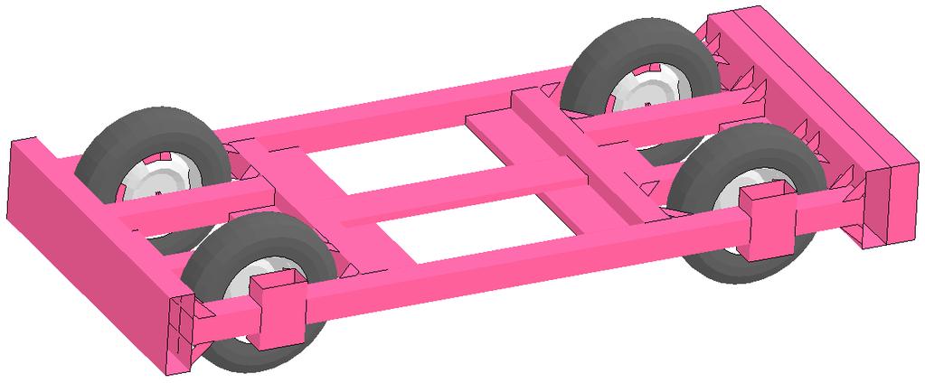
48 Figure 22. MwRSF Bogie Models 40
.")

49 Sometimes a very simplified vehicle model can be used to investigate the basic behavior of a roadside design. For example, a solid element bogie model with foam material model can be made to crush with reasonable force loads compared to a vehicle (see Figure 23). The front end of a vehicle is usually made to crush and absorb the energy of an impact, while the back end is more structurally rigid, protecting the occupant from deforming parts. That phenomenon is captured in the simple model with two different nonlinear crushing material properties. Figure 23. Solid Element Foam Bogie 4.9 Component and Subsystem Models In order to investigate and improve various portions of a model, it is common to create component and subsystem models to aid in that process. As a single example, when the Silverado suspension system needed to be investigated to determine and improve its various characteristics, the subsystem model depicted in Figure 24 was developed. With this isolated subsystem the springs, shocks, deformability, joint stiffnesses, steering, and fracturing of connections could all be examined much easier and in greater detail than just using the entire vehicle model. Figure 24. Silverado Front Suspension Subsystem 41
50 5 MGS MODELING Since 2006 the Midwest Guardrail System (MGS) has been the foundation for many subsequent projects, including the MGS with approach slopes, curbs, maximum height, minimum effective length, downstream anchorage requirements, transition to concrete barriers, and long-span. Overtime, improvement or refinement to the MGS LS-DYNA model has been required in order to continually improve MwRSF design and analysis capabilities. One such example is the modeling of the anchorage, as shown in Figure 25. Some of the projects using the MGS would use the simple anchor model when the anchorage was determined to be relatively non-influential during an impact event, saving significant cpu time. Other projects would use the most detailed version available because the anchorage behavior plays a significant role in the overall system behavior. Other aspects of the MGS model also have multiple versions and techniques deployed, including the post-in-soil models, the rail-to-post connections, and the splices. All of these have required multiple investigations to improve their usefulness. As an example, a post-in-soil modeling effort is described in Section 6. Many of the modeling details of the MGS are not as detailed or as accurate as ultimately desired for predicting system behavior. Although great strides have been made, much more remains in this area. 42


51 Figure 25. Various Modeling Approaches for MGS End Anchor
52 6 SOIL MODELING For the most part, W-beam and thrie-beam guardrail systems are installed in soil foundations. The interaction of the guardrail posts and soil is a critical factor in how a guardrail system behaves under impact conditions. In order to simulate that behavior with LS-DYNA, the post-in-soil behavior must be modeled. Over the past 23 years there have been many techniques developed to model the soil. Throughout 2014 and the first half of 2015, an attempt was made to gather the most promising soil modeling techniques and document those in a PowerPoint presentation, and generate actual LS-DYNA models that used those techniques. This work was to be shared by all those interested. As a result of that work, during the Finite Element Modeling & Crash Simulation Forum held during the 2015 TRB AFB(20) Summer Meeting in Chicago, IL, J.D. Reid led a two-hour discussion on soil modeling. The following pages contain a copy of the PowerPoint slides used to lead that discussion. The dyna decks (i.e., LS-DYNA models) used to generate much of the presentation are available. The presentation outline was as follows: Phase I Modeling Posts in Soil: Best Practices Phase II Soil Modeling Part 1 single element study Part 2 three standardized bogie cases Part 3 application: MGS upstream anchor 44

53 Figure 26. Soil Modeling: Phase I, slides
54 Figure 27. Soil Modeling: Phase I, slides
55 Figure 28. Soil Modeling: Phase I, slides

56 Figure 29. Soil Modeling: Phase I, slides

57 Figure 30. Soil Modeling: Phase I, slides

58 Figure 31. Soil Modeling: Phase I, slides

59 Figure 32. Soil Modeling: Phase I, slides
60 Figure 33. Soil Modeling: Phase I, slides

61 Figure 34. Soil Modeling: Phase II, Part 1, slides

62 Figure 35. Soil Modeling: Phase II, Part 1, slides
63 Figure 36. Soil Modeling: Phase II, Part 2, slides

64 Figure 37. Soil Modeling: Phase II, Part 2, slides

65 Figure 38. Soil Modeling: Phase II, Part 2, slides

66 Figure 39. Soil Modeling: Phase II, Part 2, slides

67 Figure 40. Soil Modeling: Phase II, Part 2, slides

68 Figure 41. Soil Modeling: Phase II, Part 2, slides

69 Figure 42. Soil Modeling: Phase II, Part 3, slides

70 Figure 43. Soil Modeling: Phase II, Part 3, slides

71 Figure 44. Soil Modeling: Phase II, Part 3, slides
72 7 FRICTION MODELING Modeling friction realistically has proven to be a very difficult phenomenon to capture; whether it s for a vehicle bumper rubbing against a w-beam rail, a bolt sliding along a slot, a tire riding up a concrete barrier, or some other common interaction between two parts during an impact event. During the Highway & Vehicle Safety Finite Element Modeling & Crash Simulation Forum held during the 2016 TRB Annual Meeting in Washington, D.C., J.D. Reid led a twohour discussion on friction modeling. The following pages contain a copy of the PowerPoint slides used to lead that discussion. Information for the discussion came from many years of investigating various frictional effects. As a result of these studies, it is highly recommended that simulation studies of roadside hardware include some sort of bracketing technique to determine the range of behavior one might expect from varying friction over a wide range of values. 64

73 Figure 45. Friction Modeling: slides
74 Figure 46. Friction Modeling: slides
75 Figure 47. Friction Modeling: slides
76 Figure 48. Friction Modeling: slides

77 Figure 49. Friction Modeling: slides

78 Figure 50. Friction Modeling: slides

79 Figure 51. Friction Modeling: slides
PR V2. Submitted by. Professor MIDWEST Vine Street (402) Submitted to
 Submitted to") FINAL REPORT PR4893118-V2 ZONE OF INTRUSION STUDY Submitted by John D. Reid, Ph.D. Professor Dean L.. Sicking, Ph.D., P.E. Professorr and MwRSF Director MIDWEST ROADSIDE SAFETY FACILITY University of Nebraska-Lincoln
FINAL REPORT PR4893118-V2 ZONE OF INTRUSION STUDY Submitted by John D. Reid, Ph.D. Professor Dean L.. Sicking, Ph.D., P.E. Professorr and MwRSF Director MIDWEST ROADSIDE SAFETY FACILITY University of Nebraska-Lincoln
Advances in Simulating Corrugated Beam Barriers under Vehicular Impact
 13 th International LS-DYNA Users Conference Session: Automotive Advances in Simulating Corrugated Beam Barriers under Vehicular Impact Akram Abu-Odeh Texas A&M Transportation Institute Abstract W-beam
Crash Testing Growth Common Roadside Hardware Systems Draft FHWA and AASHTO Requirements for Implementing MASH 2015
 64 th Annual Illinois Traffic Safety and Engineering Conference October 14, 2015 Crash Testing Growth Common Roadside Hardware Systems Draft FHWA and AASHTO Requirements for Implementing MASH 2015 1 https://www.youtube.com/watch?feature
DEFLECTION LIMITS FOR TEMPORARY CONCRETE BARRIERS
 Midwest State s Regional Pooled Fund Research Program Fiscal Year 1998-1999 (Year 9) NDOR Research Project Number SPR-3(017) DEFLECTION LIMITS FOR TEMPORARY CONCRETE BARRIERS Submitted by Dean L. Sicking,
Midwest Guardrail System Without Blockouts
 Duplication for publication or sale is strictly prohibited without prior written permission of the Transportation Research Board Paper No. 13-0418 Midwest Guardrail System Without Blockouts by John D.
AASHTO Manual for Assessing Safety Hardware, AASHTO/FHWA Joint Implementation Plan Standing Committee on Highways September 24, 2015
 AASHTO Manual for Assessing Safety Hardware, 2015 AASHTO/FHWA Joint Implementation Plan Standing Committee on Highways September 24, 2015 Full Scale MASH Crash Tests (NCHRP 22-14(02)) Conducted several
ROBUST PROJECT Norwegian Public Roads Administration / Force Technology Norway AS
 ROBUST PROJECT Norwegian Public Roads Administration / Force Technology Norway AS Evaluation of small car - RM_R1 - prepared by Politecnico di Milano Volume 1 of 1 January 2006 Doc. No.: ROBUST-5-002/TR-2004-0039
Manual for Assessing Safety Hardware
 American Association of State Highway and Transportation Officials Manual for Assessing Safety Hardware 2009 vii PREFACE Effective traffic barrier systems, end treatments, crash cushions, breakaway devices,
Continued Development of a Non-Proprietary, High-Tension, Cable End Terminal System
 University of Nebraska - Lincoln DigitalCommons@University of Nebraska - Lincoln Nebraska Department of Transportation Research Reports Nebraska LTAP 4-29-2016 Continued Development of a Non-Proprietary,
TEST MATRICES FOR EVALUATING CABLE MEDIAN BARRIERS PLACED IN V-DITCHES
 Midwest States Regional Pooled Fund Research Program Fiscal Year 2012 (Year 22) Research Project Number TPF-5(193) Supplement #44 NDOR Sponsoring Agency Code RPFP-12-CABLE1&2 TEST MATRICES FOR EVALUATING
Improving Roadside Safety by Computer Simulation
 A2A04:Committee on Roadside Safety Features Chairman: John F. Carney, III, Worcester Polytechnic Institute Improving Roadside Safety by Computer Simulation DEAN L. SICKING, University of Nebraska, Lincoln
EXTENDING TL-2 SHORT-RADIUS GUARDRAIL TO LARGER RADII
 Research Project Number TPF-5(193) Supplement 27 EXTENDING TL-2 SHORT-RADIUS GUARDRAIL TO LARGER RADII Submitted by Cody S. Stolle, Ph.D., E.I.T. Post-Doctoral Research Associate Robert W. Bielenberg,
SUMMARY CHANGES FOR NCHRP REPORT 350 GUIDELINES [NCHRP (02)] Keith A. Cota, Chairman Technical Committee on Roadside Safety June 14, 2007
![SUMMARY CHANGES FOR NCHRP REPORT 350 GUIDELINES [NCHRP (02)] Keith A. Cota, Chairman Technical Committee on Roadside Safety June 14, 2007](/thumbs/87/97351925.jpg "SUMMARY CHANGES FOR NCHRP REPORT 350 GUIDELINES [NCHRP (02)] Keith A. Cota, Chairman Technical Committee on Roadside Safety June 14, 2007") SUMMARY CHANGES FOR NCHRP REPORT 350 GUIDELINES [NCHRP 22-14 (02)] Keith A. Cota, Chairman Technical Committee on Roadside Safety June 14, 2007 BACKGROUND Circular 482 (1962) First full scale crash test
SUMMARY CHANGES FOR NCHRP REPORT 350 GUIDELINES [NCHRP 22-14 (02)] Keith A. Cota, Chairman Technical Committee on Roadside Safety June 14, 2007 BACKGROUND Circular 482 (1962) First full scale crash test
Implementation of AASHTO s Manual for Assessing Safety Hardware (MASH) 2016
 2016") Implementation of AASHTO s Manual for Assessing Safety Hardware (MASH) 2016 Update from the Technical Committee on Roadside Safety Keith Cota, New Hampshire DOT MASH 2016 Overview Background Ballot Results/Dates
Implementation of AASHTO s Manual for Assessing Safety Hardware (MASH) 2016 Update from the Technical Committee on Roadside Safety Keith Cota, New Hampshire DOT MASH 2016 Overview Background Ballot Results/Dates
DEVELOPMENT OF A TRANSITION BETWEEN FREE-STANDING AND REDUCED-DEFLECTION PORTABLE CONCRETE BARRIERS PHASE I
 Research Project Number TPF-5(193) Supplement #78 DEVELOPMENT OF A TRANSITION BETWEEN FREE-STANDING AND REDUCED-DEFLECTION PORTABLE CONCRETE BARRIERS PHASE I Submitted by Mojdeh Asadollahi Pajouh, Ph.D.
MINIMUM EFFECTIVE LENGTH FOR THE MIDWEST GUARDRAIL SYSTEM
 Duplication for publication or sale is strictly prohibited without prior written permission of the Transportation Research Board Paper No. 15-0484 MINIMUM EFFECTIVE LENGTH FOR THE MIDWEST GUARDRAIL SYSTEM
DEVELOPMENT OF A MASH TL-3 TRANSITION BETWEEN GUARDRAIL AND PORTABLE CONCRETE BARRIERS
 Duplication for publication or sale is strictly prohibited without prior written permission of the Transportation Research Board Paper No. 17-01712 DEVELOPMENT OF A MASH TL-3 TRANSITION BETWEEN GUARDRAIL
A MASH Compliant W-Beam Median Guardrail System
 0 0 0 0 0 A MASH Compliant W-Beam Median Guardrail System By A. Y. Abu-Odeh, R. P. Bligh, W. Odell, A. Meza, and W. L. Menges Submitted: July 0, 0 Word Count:, + ( figures + tables=,000) =, words Authors:
1962: HRCS Circular 482 one-page document, specified vehicle mass, impact speed, and approach angle for crash tests.
 1 2 3 1962: HRCS Circular 482 one-page document, specified vehicle mass, impact speed, and approach angle for crash tests. 1973: NCHRP Report 153 16-page document, based on technical input from 70+ individuals
INCREASED SPAN LENGTH FOR THE MGS LONG-SPAN GUARDRAIL SYSTEM
 University of Nebraska - Lincoln DigitalCommons@University of Nebraska - Lincoln Mechanical (and Materials) Engineering -- Dissertations, Theses, and Student Research Mechanical & Materials Engineering,
Development and Validation of a Finite Element Model of an Energy-absorbing Guardrail End Terminal
 Development and Validation of a Finite Element Model of an Energy-absorbing Guardrail End Terminal Yunzhu Meng 1, Costin Untaroiu 1 1 Department of Biomedical Engineering and Virginia Tech, Blacksburg,
Development of Iowa Dot Combination Bridge Separation Barrier with Bicycle Railing
 University of Nebraska - Lincoln DigitalCommons@University of Nebraska - Lincoln Engineering Mechanics Dissertations & Theses Mechanical & Materials Engineering, Department of 8-2018 Development of Iowa
CRITICAL FLARE RATES FOR W-BEAM GUARDRAIL DETERMINING MAXIMUM CAPACITY USING COMPUTER SIMULATION NCHRP 17-20(3)
") CRITICAL FLARE RATES FOR W-BEAM GUARDRAIL DETERMINING MAXIMUM CAPACITY USING COMPUTER SIMULATION NCHRP 17-2(3) Submitted by Beau D. Kuipers, B.S.M.E., E.I.T. Graduate Research Assistant Ronald K. Faller,
CRITICAL FLARE RATES FOR W-BEAM GUARDRAIL DETERMINING MAXIMUM CAPACITY USING COMPUTER SIMULATION NCHRP 17-2(3) Submitted by Beau D. Kuipers, B.S.M.E., E.I.T. Graduate Research Assistant Ronald K. Faller,
WP5 - Computational Mechanics B5 - Temporary Vertical Concrete Safety Barrier MAIN REPORT Volume 1 of 1
 ROBUST PROJECT TRL Limited WP5 - Computational Mechanics B5 - Temporary Vertical Concrete Safety Barrier MAIN REPORT Volume 1 of 1 December 2005 Doc. No.: ROBUST-5-010c Rev. 0. (Logo here) Main Report
Methodologies and Examples for Efficient Short and Long Duration Integrated Occupant-Vehicle Crash Simulation
 13 th International LS-DYNA Users Conference Session: Automotive Methodologies and Examples for Efficient Short and Long Duration Integrated Occupant-Vehicle Crash Simulation R. Reichert, C.-D. Kan, D.
MODELING SUSPENSION DAMPER MODULES USING LS-DYNA
 MODELING SUSPENSION DAMPER MODULES USING LS-DYNA Jason J. Tao Delphi Automotive Systems Energy & Chassis Systems Division 435 Cincinnati Street Dayton, OH 4548 Telephone: (937) 455-6298 E-mail: Jason.J.Tao@Delphiauto.com
INCREASED SPAN LENGTH FOR THE MGS LONG-SPAN GUARDRAIL SYSTEM PART III: FAILURE ANALYSIS
 Midwest States Pooled Fund Research Program Fiscal Years 2013 (Years 23) Research Project Number TPF-5(193) Supplement #56 NDOR Sponsoring Agency Code RPFP-13-MGS-3 INCREASED SPAN LENGTH FOR THE MGS LONG-SPAN
Evaluation and Design of ODOT s Type 5 Guardrail with Tubular Backup
 Evaluation and Design of ODOT s Type 5 Guardrail with Tubular Backup Draft Final Report Chuck A. Plaxico, Ph.D. James C. Kennedy, Jr., Ph.D. Charles R. Miele, P.E. for the Ohio Department of Transportation
Research Project Number SPR-P1(13)M326 DEVELOPMENT OF A MASH TL-3 TRANSITION BETWEEN GUARDRAIL AND PORTABLE CONCRETE BARRIERS.
M326 DEVELOPMENT OF A MASH TL-3 TRANSITION BETWEEN GUARDRAIL AND PORTABLE CONCRETE BARRIERS.") Research Project Number SPR-P1(13)M326 DEVELOPMENT OF A MASH TL-3 TRANSITION BETWEEN GUARDRAIL AND PORTABLE CONCRETE BARRIERS Submitted by David A. Gutierrez, B.S.C.E., E.I.T. Graduate Research Assistant
Research Project Number SPR-P1(13)M326 DEVELOPMENT OF A MASH TL-3 TRANSITION BETWEEN GUARDRAIL AND PORTABLE CONCRETE BARRIERS Submitted by David A. Gutierrez, B.S.C.E., E.I.T. Graduate Research Assistant
Working Paper. Development and Validation of a Pick-Up Truck Suspension Finite Element Model for Use in Crash Simulation
 Working Paper NCAC 2003-W-003 October 2003 Development and Validation of a Pick-Up Truck Suspension Finite Element Model for Use in Crash Simulation Dhafer Marzougui Cing-Dao (Steve) Kan Matthias Zink
WP5 - Computational Mechanics B1 (ESP-N2) Barrier Steel N2 MAIN REPORT Volume 2 of 2
 Barrier Steel N2 MAIN REPORT Volume 2 of 2") ROBUST PROJECT TRL Limited WP5 - Computational Mechanics B1 (ESP-N2) Barrier Steel N2 Volume 2 of 2 November 2005 Doc. No.: ROBUST 5-014b Rev. 1. (Logo here) Main Report Report title: WP5 - Computational
ROBUST PROJECT TRL Limited WP5 - Computational Mechanics B1 (ESP-N2) Barrier Steel N2 Volume 2 of 2 November 2005 Doc. No.: ROBUST 5-014b Rev. 1. (Logo here) Main Report Report title: WP5 - Computational
Development and Implementation of the Simplified MGS Stiffness Transition
 Duplication for publication or sale is strictly prohibited without prior written permission of the Transportation Research Board Paper No. 12-3367 Development and Implementation of the Simplified MGS Stiffness
Guide Rail Safety Symposium
 Ministry of Transportation Guide Rail Safety Symposium MTO Provincial Roadside Safety Update Mark C. Ayton, P. Eng. Senior Engineer, Highway Design MTO Highway Standards Branch MTO Provincial Roadside
ROBUST PROJECT Norwegian Public Roads Administration / Force Technology Norway AS
 ROBUST PROJECT Norwegian Public Roads Administration / Force Technology Norway AS Volume 1 of 1 April 2005 Doc. No.: ROBUST-05-009/TR-2005-0012 - Rev. 0 286-2-1-no-en Main Report Report title: Simulation
Cable-to-Post Attachments for Use in Non- Proprietary High-Tension Cable Median Barrier Phase II
 University of Nebraska - Lincoln DigitalCommons@University of Nebraska - Lincoln Nebraska Department of Transportation Research Reports Nebraska LTAP 3-24-2016 Cable-to-Post Attachments for Use in Non-
SAFETY PERFORMANCE OF WORK-ZONE DEVICES UNDER MASH TESTING
 SAFETY PERFORMANCE OF WORK-ZONE DEVICES UNDER MASH TESTING Schmidt, Faller, Lechtenberg, Sicking, Holloway Midwest Roadside Safety Facility Nebraska Transportation Center University of Nebraska-Lincoln
VERIFICATION & VALIDATION REPORT of MGS Barrier Impact with 1100C Vehicle Using Toyota Yaris Coarse FE Model
 VERIFICATION & VALIDATION REPORT of MGS Barrier Impact with 1100C Vehicle Using Toyota Yaris Coarse FE Model CCSA VALIDATION/VERIFICATION REPORT Page 1 of 4 Project: CCSA Longitudinal Barriers on Curved,
Development of a Finite Element Model of a Motorcycle
 Development of a Finite Element Model of a Motorcycle N. Schulz, C. Silvestri Dobrovolny and S. Hurlebaus Texas A&M Transportation Institute Abstract Over the past years, extensive research efforts have
Evaluation of the Midwest Guardrail System stiffness transition with curb
 University of Nebraska - Lincoln DigitalCommons@University of Nebraska - Lincoln Civil Engineering Faculty Publications Civil Engineering 2016 Evaluation of the Midwest Guardrail System stiffness transition
Vehicle Dynamic Simulation Using A Non-Linear Finite Element Simulation Program (LS-DYNA)
") Vehicle Dynamic Simulation Using A Non-Linear Finite Element Simulation Program (LS-DYNA) G. S. Choi and H. K. Min Kia Motors Technical Center 3-61 INTRODUCTION The reason manufacturers invest their time
Vehicle Dynamic Simulation Using A Non-Linear Finite Element Simulation Program (LS-DYNA) G. S. Choi and H. K. Min Kia Motors Technical Center 3-61 INTRODUCTION The reason manufacturers invest their time
July 10, Refer to: HSA-10/CC-78A
 July 10, 2003 Refer to: HSA-10/CC-78A Barry D. Stephens, P.E. Senior Vice President of Engineering ENERGY ABSORPTION Systems, Inc. 3617 Cincinnati Avenue Rocklin, California 95765 Dear Mr. Stephens: Your
Median Barriers in North Carolina
 Median Barriers in North Carolina AASHTO Subcommittee on Design - 2006 June 13-16, 2006 Jay A. Bennett North Carolina DOT State Roadway Design Engineer Brian Murphy, PE Traffic Safety Engineer Safety Evaluation
MASH 2016 Implementation: What, When and Why
 MASH 2016 Implementation: What, When and Why Roger P. Bligh, Ph.D., P.E. Senior Research Engineer Texas A&M Transportation Institute June 7, 2016 2016 Traffic Safety Conference College Station, Texas Outline
Assessing Options for Improving Roadside Barrier Crashworthiness
 13 th International LS-DYNA Users Conference Session: Simulation Assessing Options for Improving Roadside Barrier Crashworthiness D. Marzougui, C.D. Kan, and K.S. Opiela Center for Collision Safety and
VULCAN BARRIER TL-3 GENERAL SPECIFICATIONS
 VULCAN BARRIER TL-3 GENERAL SPECIFICATIONS I. GENERAL A. The VULCAN BARRIER TL-3 (VULCAN TL-3) shall be a highly portable and crashworthy longitudinal barrier especially suited for use as a temporary barrier
PRODUCT DESCRIPTION. X-Tension DS. is suitable for all road types: Motorways, country roads, city streets for speed categories up to 110 km/h.
 INDEX Introduction 2 Product Description 3 Installation 6 Specifications 7 Crash Tests Table 8 Reusability 9 FAQ 10 Annexes 14 Drawings 15 Pictures 16 Crash Tests Results 18 Approvals 23 INTRODUCTION Improving
DYNAMICS AND SAFETY ASSESSMENT OF A TRUCK IMPACT ONTO VARIOUS TYPES OF ROADSIDE CONCRETE BARRIERS ON CURVED ROADS. A Thesis by. Prasanna K Parvatikar
 DYNAMICS AND SAFETY ASSESSMENT OF A TRUCK IMPACT ONTO VARIOUS TYPES OF ROADSIDE CONCRETE BARRIERS ON CURVED ROADS A Thesis by Prasanna K Parvatikar Master of Science, Wichita State University, 2007 Bachelor
February 8, In Reply Refer To: HSSD/CC-104
 February 8, 2008 200 New Jersey Avenue, SE. Washington, DC 20590 In Reply Refer To: HSSD/CC-04 Barry D. Stephens, P.E. Sr. Vice President Engineering Energy Absorption Systems, Inc. 367 Cincinnati Avenue
Design Evaluation of Fuel Tank & Chassis Frame for Rear Impact of Toyota Yaris
 International Research Journal of Engineering and Technology (IRJET) e-issn: 2395-0056 Volume: 03 Issue: 05 May-2016 p-issn: 2395-0072 www.irjet.net Design Evaluation of Fuel Tank & Chassis Frame for Rear
An Analysis of Less Hazardous Roadside Signposts. By Andrei Lozzi & Paul Briozzo Dept of Mechanical & Mechatronic Engineering University of Sydney
 An Analysis of Less Hazardous Roadside Signposts By Andrei Lozzi & Paul Briozzo Dept of Mechanical & Mechatronic Engineering University of Sydney 1 Abstract This work arrives at an overview of requirements
Update to NCHRP Report 350. Current Safety Issues
 Workshop on the Update to NCHRP Report 350 and Current Safety Issues July 18 21, 2004 Sponsored by TRB COMMITTEE AFB20 ROADSIDE SAFETY DESIGN DoubleTree Hotel Overland Park-Corporate Woods 10100 College
Illinois Safety Program IDOT District ATSSA Workshop
 Illinois Safety Program IDOT District ATSSA Workshop Roadway Departure & MASH DRAFT IDOT Facilitator: Dave Piper ATSSA Facilitator: Jim Thonn 1 Illinois Emphasis Area Priority Pyramid 2 Fatalities and
Evaluation of the Midwest Guardrail System Stiffness Transition with Curb
 Duplication for publication or sale is strictly prohibited without prior written permission of the Transportation Research Board Paper No. -0 Evaluation of the Midwest Guardrail System Stiffness Transition
June 5, In Reply Refer To: HSSD/B-178. Mr. Kevin K. Groeneweg Mobile Barriers LLC Genesee Trail Road Golden, CO Dear Mr.
 June 5, 2008 1200 New Jersey Avenue, SE. Washington, DC 20590 In Reply Refer To: HSSD/B-178 Mr. Kevin K. Groeneweg Mobile Barriers LLC 24918 Genesee Trail Road Golden, CO 80401 Dear Mr. Groeneweg: This
Development of a Moving Automatic Flagger Assistance Device (AFAD) for Moving Work Zone Operations
 for Moving Work Zone Operations") Development of a Moving Automatic Flagger Assistance Device (AFAD) for Moving Work Zone Operations Edward F. Terhaar, Principal Investigator Wenck Associates, Inc. March 2017 Research Project Final Report
Development of a Moving Automatic Flagger Assistance Device (AFAD) for Moving Work Zone Operations Edward F. Terhaar, Principal Investigator Wenck Associates, Inc. March 2017 Research Project Final Report
Toyota Motor North America, Inc. Grant of Petition for Temporary Exemption from an Electrical Safety Requirement of FMVSS No. 305
 This document is scheduled to be published in the Federal Register on 01/02/2015 and available online at http://federalregister.gov/a/2014-30749, and on FDsys.gov DEPARTMENT OF TRANSPORTATION National
Skid against Curb simulation using Abaqus/Explicit
 Visit the SIMULIA Resource Center for more customer examples. Skid against Curb simulation using Abaqus/Explicit Dipl.-Ing. A. Lepold (FORD), Dipl.-Ing. T. Kroschwald (TECOSIM) Abstract: Skid a full vehicle
June 27, In Reply Refer To: HSSD/B-176
 June 27, 2008 1200 New Jersey Avenue, SE. Washington, DC 20590 In Reply Refer To: HSSD/B-176 Mr. John Addy Hill & Smith Springvale Business and Industrial Park Bliston, Wolverhampton, West Midlands, UK,
Funding Scenario Descriptions & Performance
 Funding Scenario Descriptions & Performance These scenarios were developed based on direction set by the Task Force at previous meetings. They represent approaches for funding to further Task Force discussion
Vehicle Seat Bottom Cushion Clip Force Study for FMVSS No. 207 Requirements
 14 th International LS-DYNA Users Conference Session: Automotive Vehicle Seat Bottom Cushion Clip Force Study for FMVSS No. 207 Requirements Jaehyuk Jang CAE Body Structure Systems General Motors Abstract
Median Barriers in North Carolina -- Long Term Evaluation. Safety Evaluation Group Traffic Safety Systems Management Section
 Median Barriers in North Carolina -- Long Term Evaluation Safety Evaluation Group Traffic Safety Systems Management Section Background In 1998 North Carolina began a three pronged approach to prevent and
Development of Turning Templates for Various Design Vehicles
 Transportation Kentucky Transportation Center Research Report University of Kentucky Year 1991 Development of Turning Templates for Various Design Vehicles Kenneth R. Agent Jerry G. Pigman University of
Improvement Design of Vehicle s Front Rails for Dynamic Impact
 5 th European LS-DYNA Users Conference Crash Technology (1) Improvement Design of Vehicle s Front Rails for Dynamic Impact Authors: Chien-Hsun Wu, Automotive research & testing center Chung-Yung Tung,
FHWA/IN/JTRP-2000/23. Final Report. Sedat Gulen John Nagle John Weaver Victor Gallivan
 FHWA/IN/JTRP-2000/23 Final Report DETERMINATION OF PRACTICAL ESALS PER TRUCK VALUES ON INDIANA ROADS Sedat Gulen John Nagle John Weaver Victor Gallivan December 2000 Final Report FHWA/IN/JTRP-2000/23 DETERMINATION
SGR52 TOP-MOUNTED WEAK-POST GUARDRAIL ATTACHED TO CULVERT PLAN VIEW ELEVATION VIEW DETAIL B DETAIL A SHEET NO. DATE: 37 1/2" 953 (TYP) 150" 3810
 150 3810") PLAN VIEW C 150" 3810 37 1/2" 953 (TYP) A B C 8-FBB01 RWB01a FWR01 RWM04a FWR01 RWB01a RWM04a PSF01 FBX08a PSF01 FBX08a DETAIL A DETAIL B 1 of 7 12/5/2016 INTENDED USE The Top-Mounted Weak-Post Guardrail
PLAN VIEW C 150" 3810 37 1/2" 953 (TYP) A B C 8-FBB01 RWB01a FWR01 RWM04a FWR01 RWB01a RWM04a PSF01 FBX08a PSF01 FBX08a DETAIL A DETAIL B 1 of 7 12/5/2016 INTENDED USE The Top-Mounted Weak-Post Guardrail
Heating Comparison of Radial and Bias-Ply Tires on a B-727 Aircraft
 'S Heating Comparison of Radial and Bias-Ply Tires on a B-727 Aircraft November 1997 DOT/FAA/AR-TN97/50 This document is available to the U.S. public through the National Technical Information Service
(Item 1) PSS - Type III barricade with a lightweight light attachment, and with a variation in the panel spacing;
 PSS - Type III barricade with a lightweight light attachment, and with a variation in the panel spacing;") Refer to: HSA-10/WZ-102 Mr. Chuck Bailey Plastic Safety Systems, Inc. 2444 Baldwin Road Cleveland, OH 44104 Dear Mr. Bailey: Thank you for your letter of February 19, 2002, requesting Federal Highway Administration
Refer to: HSA-10/WZ-102 Mr. Chuck Bailey Plastic Safety Systems, Inc. 2444 Baldwin Road Cleveland, OH 44104 Dear Mr. Bailey: Thank you for your letter of February 19, 2002, requesting Federal Highway Administration
Remote Combination Adaptive Driving Equipment Investigation Dynamic Science, Inc. (DSI), Case Number G 1990 Ford Bronco Arizona October
, Case Number G 1990 Ford Bronco Arizona October") Remote Combination Adaptive Driving Equipment Investigation Dynamic Science, Inc. (DSI), Case Number 2007-76-131G 1990 Ford Bronco Arizona October 2007 This document is disseminated under the sponsorship
Remote Combination Adaptive Driving Equipment Investigation Dynamic Science, Inc. (DSI), Case Number 2007-76-131G 1990 Ford Bronco Arizona October 2007 This document is disseminated under the sponsorship
Residential Load Profiles
 Residential Load Profiles TABLE OF CONTENTS PAGE 1 BACKGROUND... 1 2 DATA COLLECTION AND ASSUMPTIONS... 1 3 ANALYSIS AND RESULTS... 2 3.1 Load Profiles... 2 3.2 Calculation of Monthly Electricity Bills...
D-25 Speed Advisory System
 Report Title Report Date: 2002 D-25 Speed Advisory System Principle Investigator Name Pesti, Geza Affiliation Texas Transportation Institute Address CE/TTI, Room 405-H 3135 TAMU College Station, TX 77843-3135
Studying the Effect of Caster Angle on Wheel Parameters by Dynamic Analysis Using ADAMS CAR Software
 IJSRD - International Journal for Scientific Research & Development Vol. 5, Issue 04, 2017 ISSN (online): 2321-0613 Studying the Effect of Caster Angle on Wheel Parameters by Dynamic Analysis Using ADAMS
VULCAN BARRIER TL-3 GENERAL SPECIFICATIONS
 VULCAN BARRIER TL-3 GENERAL SPECIFICATIONS I. GENERAL A. The VULCAN BARRIER TL-3 (VULCAN TL-3) shall be a highly portable and crashworthy longitudinal barrier especially suited for use as a temporary barrier
Crashworthiness Evaluation of an Impact Energy Absorber in a Car Bumper for Frontal Crash Event - A FEA Approach
 Crashworthiness Evaluation of an Impact Energy Absorber in a Car Bumper for Frontal Crash Event - A FEA Approach Pravin E. Fulpagar, Dr.S.P.Shekhawat Department of Mechanical Engineering, SSBTS COET Jalgaon.
Roadside Safety MASH
 Ministry of Transportation MEA 2016 ANNUAL WORKSHOP AND GENERAL MEETING Roadside Safety MASH MTO Design & Contract Standards Office Highway Standards Branch November 24, 2016 Roadside Safety - MASH Highway
ON-ROAD FUEL ECONOMY OF VEHICLES
 SWT-2017-5 MARCH 2017 ON-ROAD FUEL ECONOMY OF VEHICLES IN THE UNITED STATES: 1923-2015 MICHAEL SIVAK BRANDON SCHOETTLE SUSTAINABLE WORLDWIDE TRANSPORTATION ON-ROAD FUEL ECONOMY OF VEHICLES IN THE UNITED
TRACC. Trinity Attenuating Crash Cushion
 TRACC Trinity Attenuating Crash Cushion CSP Pacific Business Unit of Fletcher Concrete & Infrastructure Limited 306 Neilson Street Onehunga, Auckland Phone: (09) 634 1239 or 0800 655 200 Fax: (09) 634
800 Access Control, R/W Use Permits and Drive Design
 Table of Contents 801 Access Control... 8-1 801.1 Access Control Directives... 8-1 801.2 Access Control Policies... 8-1 801.2.1 Interstate Limited Access... 8-1 801.2.2 Limited Access... 8-1 801.2.3 Controlled
Crash Performance of Strong-Post W-Beam Guardrail with Missing Blockouts Carolyn E. Hampton and Hampton C. Gabler
 Crash Performance of Strong-Post W-Beam Guardrail with Missing Blockouts Carolyn E. Hampton and Hampton C. Gabler Virginia Tech Center for Injury Biomechanics, Blacksburg VA 24061 Abstract Missing blockouts
Product Specification. ABSORB 350 TM TL-2 Non-Redirective, Gating, Crash Cushion Applied to Quickchange Moveable Barrier
 TB 000612 Rev. 0 Page 1 of 9 Product Specification ABSORB 350 TM TL-2 Non-Redirective, Gating, Crash Cushion Applied to Quickchange Moveable Barrier I. General The ABSORB 350 TM TL-2 System is a Non-Redirective,
Using ABAQUS in tire development process
 Using ABAQUS in tire development process Jani K. Ojala Nokian Tyres plc., R&D/Tire Construction Abstract: Development of a new product is relatively challenging task, especially in tire business area.
METAL BEAM GUARDFENCE TRANSITION AND END TREATMENT IDENTIFICATION GUIDE
 2016 TxDOT Design Division METAL BEAM GUARDFENCE TRANSITION AND END TREATMENT IDENTIFICATION GUIDE A guide to help TxDOT employees identify metal beam guardfence transitions and end treatments for the
KENTUCKY TRANSPORTATION CENTER
 Research Report KTC-08-10/UI56-07-1F KENTUCKY TRANSPORTATION CENTER EVALUATION OF 70 MPH SPEED LIMIT IN KENTUCKY OUR MISSION We provide services to the transportation community through research, technology
Form DOT F (8-72) Texas Transportation Institute The Texas A&M University System College Station, Texas
 Texas Transportation Institute The Texas A&M University System College Station, Texas") 1. Report No. FHWA/TX-02/4162-1 Technical Report Documentation Page 2. Government Accession No. 3. Recipient's Catalog No. 4. Title and Subtitle EVALUATION OF TEXAS GRID-SLOT PORTABLE CONCRETE BARRIER
1. Report No. FHWA/TX-02/4162-1 Technical Report Documentation Page 2. Government Accession No. 3. Recipient's Catalog No. 4. Title and Subtitle EVALUATION OF TEXAS GRID-SLOT PORTABLE CONCRETE BARRIER
Crashworthiness Analysis with Abaqus
 Crashworthiness Analysis with Abaqus 2017 About this Course Course objectives This course covers: Abaqus fundamentals and input syntax General "automatic" contact modeling Element selection for crash simulation
CONTENTS I. INTRODUCTION... 2 II. SPEED HUMP INSTALLATION POLICY... 3 III. SPEED HUMP INSTALLATION PROCEDURE... 7 APPENDIX A... 9 APPENDIX B...
 Speed Hump Program CONTENTS I. INTRODUCTION... 2 II. SPEED HUMP INSTALLATION POLICY... 3 1. GENERAL... 3 2. ELIGIBILITY REQUIREMENTS... 3 A. PETITION... 3 B. OPERATIONAL AND GEOMETRIC CHARACTERISTICS OF
Bushing connector application in Suspension modeling
 Bushing connector application in Suspension modeling Mukund Rao, Senior Engineer John Deere Turf and Utility Platform, Cary, North Carolina-USA Abstract: The Suspension Assembly modeling in utility vehicles
April 22, In Reply Refer To: HSA-10/WZ-206. Mr. Jan Miller TrafFix Devices 220 Calle Pintoresco San Clemente, California Dear Mr.
 April 22, 2005 400 Seventh St., S.W. Washington, D.C. 20590 In Reply Refer To: HSA-10/WZ-206 Mr. Jan Miller TrafFix Devices 220 Calle Pintoresco San Clemente, California 92672 Dear Mr. Miller: Thank you
ADVANCED HIGH-STRENGTH STEEL FRONT RAIL SYSTEM PHASE II
 ADVANCED HIGH-STRENGTH STEEL FRONT RAIL SYSTEM PHASE II John Catterall General Motors Corporation Background Lightweighting initiatives have demonstrated that advanced high strength steels (AHSS) can be
CFIRE December 2009
 i BRIDGE ANALYSIS AND EVALUATION OF EFFECTS UNDER OVERLOAD VEHICLES (PHASE 1) CFIRE 02-03 December 2009 National Center for Freight & Infrastructure Research & Education College of Engineering Department
July 17, In Reply Refer To: HSSD/B-176A
 July 17, 2008 1200 New Jersey Avenue, SE. Washington, DC 20590 In Reply Refer To: HSSD/B-176A Mr. John Addy Hill & Smith Springvale Business and Industrial Park Bliston, Wolverhampton, West Midlands, UK,
Extracting Tire Model Parameters From Test Data
 WP# 2001-4 Extracting Tire Model Parameters From Test Data Wesley D. Grimes, P.E. Eric Hunter Collision Engineering Associates, Inc ABSTRACT Computer models used to study crashes require data describing
Simulation of Structural Latches in an Automotive Seat System Using LS-DYNA
 Simulation of Structural Latches in an Automotive Seat System Using LS-DYNA Tuhin Halder Lear Corporation, U152 Group 5200, Auto Club Drive Dearborn, MI 48126 USA. + 313 845 0492 thalder@ford.com Keywords:
BarrierGate. General Specifications. Manual Operations General Specifications
 BarrierGate General Specifications Manual Operations General Specifications BarrierGate GENERAL SPECIFICATIONS I. GENERAL A. The BarrierGate system (the gate) shall be designed and manufactured by Energy
NUMERICAL ANALYSIS OF IMPACT BETWEEN SHUNTING LOCOMOTIVE AND SELECTED ROAD VEHICLE
 Journal of KONES Powertrain and Transport, Vol. 21, No. 4 2014 ISSN: 1231-4005 e-issn: 2354-0133 ICID: 1130437 DOI: 10.5604/12314005.1130437 NUMERICAL ANALYSIS OF IMPACT BETWEEN SHUNTING LOCOMOTIVE AND
Overview of LSTC s LS-DYNA Anthropomorphic Models
 Overview of LSTC s LS-DYNA Anthropomorphic Models Christoph Maurath, Sarba Guha, Dilip Bhalsod, Mike Burger, Jacob Krebs, Suri Bala Livermore Software Technology Corporation Sebastian Stahlschmidt, Reuben
REPORT NUMBER: 301-CAL SAFETY COMPLIANCE TESTING FOR FMVSS 301 FUEL SYSTEM INTEGRITY HONDA MOTOR COMPANY 2007 HONDA ACCORD 4-DOOR SEDAN
 REPORT NUMBER: 301-CAL-07-05 SAFETY COMPLIANCE TESTING FOR FMVSS 301 FUEL SYSTEM INTEGRITY HONDA MOTOR COMPANY 2007 HONDA ACCORD 4-DOOR SEDAN NHTSA NUMBER: C75304 CALSPAN TEST NUMBER: 8832-F301-05 CALSPAN
Finite Element Modeling and Analysis of Crash Safe Composite Lighting Columns, Contact-Impact Problem
 9 th International LS-DYNA Users Conference Impact Analysis (3) Finite Element Modeling and Analysis of Crash Safe Composite Lighting Columns, Contact-Impact Problem Alexey Borovkov, Oleg Klyavin and Alexander
Motorcycle ATV Braking Data Analysis. Progress Report
 Motorcycle ATV Braking Data Analysis Progress Report Mark D. Osborne And Russ G. Alger Keweenaw Research Center Houghton, MI 49931 February 14 TABLE OF CONTENTS Page 1. INTRODUCTION... 1 2. MOTORCYCLE
Use of Flow Network Modeling for the Design of an Intricate Cooling Manifold
 Use of Flow Network Modeling for the Design of an Intricate Cooling Manifold Neeta Verma Teradyne, Inc. 880 Fox Lane San Jose, CA 94086 neeta.verma@teradyne.com ABSTRACT The automatic test equipment designed
SAE Mini BAJA: Suspension and Steering
 SAE Mini BAJA: Suspension and Steering By Zane Cross, Kyle Egan, Nick Garry, Trevor Hochhaus Team 11 Progress Report Submitted towards partial fulfillment of the requirements for Mechanical Engineering