DYNAMICS AND SAFETY ASSESSMENT OF A TRUCK IMPACT ONTO VARIOUS TYPES OF ROADSIDE CONCRETE BARRIERS ON CURVED ROADS. A Thesis by. Prasanna K Parvatikar
|
|
|
- Delilah Floyd
- 5 years ago
- Views:
Transcription
1 DYNAMICS AND SAFETY ASSESSMENT OF A TRUCK IMPACT ONTO VARIOUS TYPES OF ROADSIDE CONCRETE BARRIERS ON CURVED ROADS A Thesis by Prasanna K Parvatikar Master of Science, Wichita State University, 2007 Bachelor of Engineering, Visvesvaraya Technological University, India, 2004 Submitted to the Department of Mechanical Engineering and the faculty of the Graduate School of Wichita State University in partial fulfillment of the requirements for the degree of Master of Science May 2013
2 Copyright 2013 by Prasanna K Parvatikar All Rights Reserved ii
3 DYNAMICS AND SAFETY ASESSMENT OF A TRUCK IMPACT ONTO VARIOUS TYPES OF ROADSIDE CONCRETE BARRIERS ON CURVED ROADS The following faculty members have examined the final copy of this thesis for form and content, and recommend that it be accepted in partial fulfillment of the requirements for the degree of Master of Science with a major in Mechanical Engineering. Hamid M. Lankarani, Committee Chair Michael L. McCoy, Committee Member Krishna Krishnan, Committee Member iii
4 DEDICATION To My Dear Swetha iv
5 ACKNOWLEDGEMENTS The words cannot explain how blessed are the students and the Department of Mechanical Engineering at Wichita State University to have Dr. Hamid Lankarani as a professor. I whole heartedly thank Dr. Lankarani for giving me this opportunity to pursue thesis under his guidance. It was his persistent motivation and encouragement without which this research wouldn t have been a reality. I also would like to thank Dr. Krishna Krishnan and Dr. Michael L. McCoy for taking there valuable time out for reviewing my thesis and giving me with their valuable inputs towards betterment of this thesis. Last but not the least, I would like to thank my family and friends for being a pillar of support for me and standing by me in every thick and thin of life. v
6 ABSTRACT Every vehicle manufacturing company invests time and money in researching all the possible ways of eliminating the serious injury to the occupants. These efforts are concentrated on making the vehicle structure and interior robust enough to absorb all the impact loads, as well as development of means to contain the occupants by seatbelts and airbags, thereby reducing the possibilities of impact injuries. The approach might vary but the intent will always remain the occupant safety. The objective of this study is to analyze the barrier design safety performance deployed on the highway roadsides. Having many different designs of roads, it is impossible to have similar kind of roadside barriers on all locations. Some barriers will perform better on particular road designs and some will not. Hence, a detailed study is conducted here to analyze and document the behavior of vehicles after impact onto different types of design barriers at different road conditions. A finite element analysis is conducted using the LS-DYNA finite element (FE) code with a modeling tool HYPERMESH. The analytical results from simulation are compared with the test results from literature. Next, the influence of many different parameters such as road curvature, slope on barrier design, vehicle speed etc., on the occupant safety are studied. The study also focuses on analyzing the effect of these parameters on vehicle lift, roll, occupant impact velocity, occupant ride-down acceleration and angular acceleration. The results from this study indicate that even though New Jersey barrier design increases the vehicle lift and occupant impact velocity, it makes sure that the vehicle does not vault the barrier and enter the other side of the traffic. The study also identifies the impact angle to be more critical than the road curvature. Hence, deploying the proper barrier designs based on the road curvature will ensure occupant safety. vi
7 TABLE OF CONTENTS Chapter Page 1 INTRODUCTION Background Motivation LITERATURE REVIEW OBJECTIVES AND METHODOLOGY Objectives Methodology Shape of the Barrier New-Jersey Barrier F-Shape Barrier Vertical Wall Barrier Curvature of the Road Impact Angle Impact Velocity of the Vehicle MODELING AND ANALYSIS Modeling Tools Vehicle Modeling Barrier Modeling MODEL VALIDATION AND PARAMETRIC DESIGN STUDY Model Validation Parametric Study Results and Discussions Design of Experiments (DOE) Effect of Input Velocity CONCLUSIONS AND FUTURE WORK Conclusions Recommendations for Future Work REFERENCES APPENDIX vii
8 LIST OF TABLES Table Page Table 4.1 Vehicle Model Summary...24 Table 4.3 Material Properties...24 Table 5.1 Summary of Performance of New-Jersey Barrier...34 Table 5.2 Summary of Performance of F-Shape Barrier...35 Table 5.3 Summary of Performance of Vertical Wall Barrier...35 viii
9 LIST OF FIGURES Figure Page 1.1 Flow chart for barrier design [2] Typical Highway Roadside Barrier and Pickup Truck [7] Single Unit Truck Vaulting over the New Jersey Barrier [5] Effect of Varying Heights of Barriers on SUT [5] Methodology of the Analysis Highway road curvatures New Jersey Shape Barrier F-Shape Barrier Vertical Wall Barrier Roadside Barrier Curvature Models (Flat, 75m Radius, 150m Radius) Vehicle Impact at Different Angles Chevrolet C2500 FE model Barrier Constraints with all DOF Barrier FE models Simulation (from this Study) and Test Model (from [1]) Comparison (Front View) Simulation (from this Study) and Test Model (from [1]) Comparison (Top View) Simulation and Test Model Roll, Pitch and Yaw Comparison from this study Roll, Pitch and Yaw Comparison from NCAC 2011-W-005 [1] Vehicle Lift Node Center of Gravity point of the Vehicle Roll Acceleration Vehicle Lift for New Jersey Barrier Vehicle Impact onto New Jersey Barrier with 75m Radius Vehicle Lift vs. Impact Angle Vehicle Roll Vs. Impact Angle Occupant Ride-Down Acceleration Vs. Impact Angle Occupant Impact Velocity Vs Impact Angle Angular Acceleration Vs Impact Angle...40 ix
10 LIST OF FIGURES (cont'd) Figure Page 5.15 Vehicle Penetrations into the Barrier ANOVA for New Jersey Barrier ANOVA for F-Shape Barrier ANOVA for Vertical Wall Barrier Velocity vs. Vehicle Lift...44 x
11 LIST OF ABBREVIATIONS NCAC NCHRP FHWA MASH SUT NJ FE ORA OIV DOE ANOVA National Crash Analysis Center National Cooperative Highway Research Program Federal Highway Administration Manual for Assessment of Safety Hardware Single Unit Truck New Jersey Finite Element Occupant Ride-Down Acceleration Occupant Impact Velocity Design of Experiments Analysis of Variance xi
12 CHAPTER ONE 1 INTRODUCTION 1.1 Background It is evident that the safety of the vehicle on the highways has been a major concern for several decades now. A detailed research and improvements have been introduced over the time to reduce the possibilities of death or severe injuries in case of an accident. In the path of this improvement, one of the prime areas of concentration has been the concrete barrier on the highway roadside. Over the years, a series of recommendations for the barrier design change have been made and the possibilities of improvements in the safety have been shown by the detailed analysis. Even though there has been a commendable improvement in the safety, a window of improvement and possibility of making the life less injury prone will always be there. The National Cooperative Highway Research Program (NCHRP) Report 350 was published in 1993 with the recommendations for the procedure to evaluate the safety barriers deployed on the highways [2]. In 1998, Federal Highway Administration implemented and ordered to have all the barriers deployed on the highways to meet the requirement of the Report 350 [2]. NCHRP Report 350 gave a detailed procedure to be followed while performing the vehicle safety test and also designing the roadside barriers. The most important aspect of Report 350 was to bring uniformity in the parameters pertaining to the vehicle and barrier safety tests. That gave highway road designers a common set of parameters to compare safety performances of barrier designs analyzed by various companies. The guidelines presented in the Report 350 helps in designing a new barrier or modifying existing design with a set of acceptable performance level to meet the required safety standard. 1
13 As the parameters involved in designing the barriers are innumerous, the guidelines are laid down only for the severe accidental conditions. Though different road conditions are available, Report 350 mentions guideline only for straight road conditions. A standard set of parameters are defined as far as vehicle speed, mass, impact angle and shape of barrier is concerned. For defining the vehicle mass, a few ranges of vehicles like, compact, pickup trucks and vans are considered. The impact velocity and impact angle ranges to a vast degree, for the purpose of defining the parameters these have been considered according to the road design. For analyzing the crash test results, Report 350 defines three major factors as structural adequacy, occupant safety and vehicle trajectory after impact. Structural adequacy solely depends on the vehicle design robustness. Occupant safety and vehicle trajectory depends on the road and barrier designs. It also depends on the possibility of occupant impact with the vehicle interior and the level of seriousness of the injury. Vehicle trajectory is assessed depending on the lift and roll of the vehicle after the impact on to the barrier design. As explained in NCHRP Report 350 [2], Figure 1.1 shows the flow chart for design process for roadside barriers. The barriers designs have to go through a research and developmental phase, experimental phase and then operational. A series of crash tests are conducted and the results are analyzed. If the results pass the set criteria then the design is sent to experimental phase. Depending on the type of design and its usage, it is installed in small numbers to examine the model in experimental phase. Once the experimental phase results are satisfactory and then the designs are implemented on large scale but still are kept under the close surveillance of performance. According to the Report 350, the performance evaluation of the design while in service and in operation is very important. The satisfactory performance in an ideal condition 2
14 does not guarantee the safety in an actual situation because of innumerous variability included. This will keep a check on the performance of the barrier on actual crash scenario. Figure 1.1 Flow chart for barrier design [2] 1.2 Motivation When a vehicle loses its control and steers towards out of the road, the roadside barriers must ensure that the vehicle is pushed back on to the road, there by not allowing it to enter the other side of the road and avoiding any head on collision. There are a series of research institutes which are exclusively working on the safety of the occupant during the crash of the vehicle. One of them has been National Crash Analysis Center (NCAC) [2]. Continuous improvements in the designs of the roadside barriers have been recommended by the support of detailed analysis. Because of the many parameters involved in the analysis, recommending any one design of the roadside barrier is not possible. It always depends on the elevation of the road, speed of the 3

15 vehicle traveling, weight and height of the vehicle. But a design feasible to reduce the chances of the severe injury to the occupant is always possible. Figure 1.2 shows a typical highway roadside barrier with pickup truck. Figure 1.2 Typical Highway Roadside Barrier and Pickup Truck [7] The most reliable source of understanding the impact behavior is performing a fullfledged crash test. But these tests are very complex, time consuming and expensive. As it always involves a series of combination of tests to be performed due to many parameters affecting the outcome, no one test will be sufficient for the final design. Therefore the testing will have a set of combination tests with different, vehicle design, different barrier design and different speeds. The NCHRP Report 350 has a detailed table for test conditions for different vehicle type and impact condition [2]. But, there will be some test conditions like the roadside safety features located on the edge of the slope, side impact condition and non-tracking kind of impacts which cannot be analyzed with the help of actual physical test. Hence in order to avoid these complications, a finite element analysis has been introduced. It is a process of using dynamic, structural analysis to predict the vehicle crash 4
16 behavior which uses a numerical analysis technique. The FE analysis technique has many advantages over the actual tests. The primary advantage includes the cost effectiveness. It reduces a significant amount of test setup time for actual physical tests. The combinations of test to be performed are easy, once the initial model of the vehicle and the barrier designs are finalized. After that, it will be just modifying the impact angle and the vehicle speed to achieve the different combinations required. 5
17 CHAPTER TWO 2 LITERATURE REVIEW The roads are comprised of different elevation and different curvatures. The result of the crash accidents depends on many parameters such as design of the barrier, velocity of the vehicle, curvature of the road and many more. The researchers have always been intrigued by the possibility of difference in impact with a small difference in any of these parameters. Though there are many barrier models being used on the highways, there are only three main highway roadside barriers which are mostly used. Section 3.3 explains these three barrier design in detail. The sole purpose of the roadside barrier is to avoid the possibilities of serious injury to the occupant of the vehicle at the time of the crash. The barrier should make sure that the vehicle remains within the boundary of the road thereby avoiding interface with the vehicles on the opposite side of the road. The barrier should decelerate the vehicle and bring it to halt at a decent distance by eliminating any possibilities of serious injury to the occupant. A detailed study of these three barriers on the safety of the occupant when the road is curved and elevated at a certain degrees has been conducted by Marzougui, et al. [1]. In this study, the effort was made to understand any need for design improvements of the barriers. Even the placement of the barrier on the road depending on the curvature and elevation of the road was also studied. The finite element model generation and the comparison of the analysis to that of the test results were demonstrated. Care was taken to follow the crash test guidelines mentioned in the NCHRP Report 350 [2]. The NCHRP Report 350 [2] gives a set of guidelines for the crash test of different size and models of vehicles on different types of barriers. During the crash analysis for this thesis, 6
18 care has also been taken to follow the guidelines mentioned in this NCHRP report 350. This report pertains to the severe accidental conditions rather than average highway conditions. Following this report, a researcher can compare his analysis impact performance, give guidelines for safety measures based on the analysis and can also generate safety specifications. As impact behavior varies drastically depending on the type of the barrier, the test requirements also varies accordingly. A cable barrier deflects a lot compared to the concrete barrier, making less impact forces for the former. A detailed test requirements specific to the test parameters have been discussed [2]. The NCHRP 350 is applicable to three different phases of the design which are research and development, testing and performance. The initial phase of the design is generated by engineering research and current design surveys and a set of evaluation criteria are set. Then the design should pass through the evaluation criteria which will be installed and subjected to performance evaluation tests. Once the performance test conditions are passed it will be installed onto the operational phase and the practical operational phase is closely monitored. The safety features for the vehicle on the highways are evaluated by series of crash tests on a limited range of testing conditions. The NCHRP report [2] goes on to say that the tests found to be pass during the testing conditions are merely not the final design safety conclusion. The in-service performance is also a critical testing for the design which might include many parameters which will not be considered during the performance test phase. This report generated three test levels, with 31 mph, 43 mph and 62 mph. Levels 4, 5 and 6 are for larger truck crash cases. Details on test parameters, test articles, test vehicles and test conditions are provided in [2]. As the NCHRP report 350 [2] was generated in 1993, there has been an immense need for upgrading this report to include the modern advanced vehicle test cases into it. That gave 7
19 birth to the Manual for Assessing Safety Hardware (MASH) in 2009 [4]. The vehicle test weights have been increased in MASH and also mid-size car has been added to the list. The angle of impact for small size cars has been increased from 20 degrees to 25 degrees. The velocity of the vehicle has been kept as 100 kmph (62 mph). Typically the barriers and rest of the road safety hardware are designed for normal or tangent roads. When there is a case of road widening or a very small curvature in the road, the question of safety arises that how well these barriers will be safe and there are no analysis data supporting this factor. Some of the design barriers (e.g. New Jersey) have a very steep curvature face. This may result in the vehicle overriding the barrier or rolling over depending on the height of the vehicle bumper. Elham, et al [5] have studies the behavior of the single unit truck on the steep curvature barriers. As Figure 2.1 indicates that the chance of truck overriding the barrier is quite immense. When NCHRP Report 350 was released in 1993, test level 4 had a Single Unit Truck (SUT) weighing 8,000 kg at 80 kmph. In 2001, there was a new addition of criteria which increased the weight of the SUT to 10,000 kg at 90 kmph. These changes raised the questions whether 32 in barrier will be able to support the SUT and avoid the vehicle from vaulting. A full scale crash analysis was performed at Midwest Roadside Safety Facility and the barrier did not fulfill the crashworthiness requirements. To evaluate the factors affecting the failures in meeting the criteria requirements, a detailed finite element analysis was performed in [5]. Three different SUT s with 8,000 kg, 10,000 kg and 12,000 kg weights were tested with three different speeds of 80 kmph, 90 kmph and 100 kmph on 32 inch New Jersey barrier model. The test did not pass for all the cases except 8,000 kg at 80 kmph. A study with the different heights of the barrier was then conducted [5]. Figure 2.2 shows the tests with 32 inch, 37 inch and 42 inch barriers in terms of roll angle to the 8

20 vehicle. The vehicle did not override with the 42-inch barrier thereby passing the criteria. Further study indicated that the barrier shape and effect of friction were negligible making the height of the barrier a crucial factor for the safety of the vehicle and the passengers. Figure 2.1 Single Unit Truck Vaulting over the New Jersey Barrier [5] 9

21 Figure 2.2 Effect of Varying Heights of Barriers on SUT [5] The NCAC report on portable barriers [8], modeled FE models using modular methods so that 160 prospective combinations could be represented consistently. Special characteristics of this paper necessitated the special attention to detail required for the FE models so that the numerical models would be flexible and are capable of simulating different conditions. The numerical models for this study were developed simulated for NCHRP Report 350 Test 3-22 conditions [8]. The best PCB and highest performance shapes were found by investigating five different safety shapes namely F, N, S, V and I. All numerical models for the different shapes have same width and length parameters [8]. Forty models were generated using eight different models and varying cross-sections, lengths and widths. Each segment was modeled precisely by mapped meshing using solid hexagonal. The geometric accuracy of these models were important and had to be precise as the mass and inertial properties of segments determined the dynamic deflection due to friction between road surface and the barrier. The accuracy helped in predicting the correct response due to interaction between barrier and vehicle that is impacting with it. The study indicates that vehicle s roll-over tendency, trajectory of the vehicle post impact and facial 10
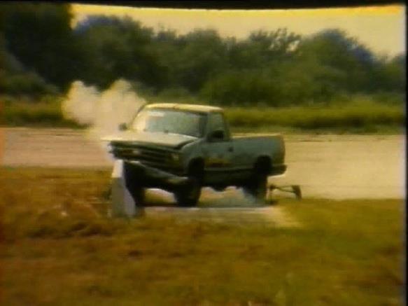
22 profiles of the barriers need to be accurately modeled for accurate simulations. Friction values determined experimentally and numerically by Marzougui, et al [8] were used for this experiment as well. In [8], it was assumed that part of the barrier is in contact with the vehicle and road pavement would behave as elastic, while the remaining segment was assumed to be rigid. Failure in the concrete material was not modeled into the segments either. To transfer impact loads between barrier and barrier and vehicle and barrier accurately, solid elements of barriers were covered with shell elements. This method of modeling was adopted to reduce the resources that would be needed to run the simulation and for faster and better performance. For the study, four different lengths were considered and modeled. The lengths chosen were 6, 10, 12 and 20 [8]. These lengths were used for varying shapes and widths of the barriers. Wider versions of each of the safety shapes were also used for this study. Gaps between barriers were either modeled in or are connected by hooks. The gap filling module was connected to one of the faces of the barriers and the other face of the barrier is coupled by a contact algorithm. This method allowed dynamic deflection and rotation between the barriers and control slack between them. The hook method was used to reduce computational time and cost. The required accuracy is achieved using this method. The hooks were modeled as beam and shell elements. The beam elements provided stiffness and account for deformations. For contact purposes, the shell elements were coupled with beams. Many researchers have studied the behavior of the crash on barrier models with different vehicle types. The research by Marzougui, et al [1] mainly explains the study of three different barriers at different curvature and impact angles. The 2000P, C2500 pick-up truck conforming to NCHRP Report 350, weighing 1000 kgs has been used to study the impact behavior. An important question has been raised here, what level of safety the standard design hardware shows 11
23 when the road designs change invariably. As we have seen in [5], the SUT overriding the barrier, there is always a chance of pickup trucks of overriding the barrier especially on the New Jersey barrier which has a steep curvature. Till 1993, there was not much research conducted with respect to the design of the barriers. In 1993 a Federal Highway Administration (FHWA) study [7] showed the importance of barrier curvature on the impact behavior. This analysis also included a 10% of super elevated upslope [7]. It is interesting to note that there has not been much of importance given to the study of barriers on curved roads. Even NCHRP Report 350 and its update, Manual for Assessment of Safety Hardware does not have clauses for curved section tests. The NCAC undertook a detailed analysis on this curved barrier issue and reported detailed results in [1]. This NCAC study concluded that the slope on the barrier increased the vehicle lift and roll. In the same way, the vehicle ride down acceleration and occupant impact velocity also increased as the slope on the barrier increases. But the important conclusion was that the curvature of the road does not impact the lift and roll as significantly. This thesis builds on the study by NCAC [1] on the safety evaluation of concrete barrier on curved roads. In addition to the parameters used in that study, other parameters including the wider range of impact speeds and smaller curvatures are considered in this thesis. In addition, other output parameters including the vehicle roll acceleration and intrusion of the vehicle have also been quantified in this thesis. A design of experiment (DOE) is also conducted to identify the most critical parameter affecting the dynamic and safety of a vehicle with a relatively high height to wheel-base ratio such as a truck. 12
24 CHAPTER THREE 3 OBJECTIVES AND METHODOLOGY 3.1 Objectives The main objective of this thesis is the study of impact behavior of the vehicle when impacted with different roadside barriers. The impact behavior is also studied to understand the need for any design modifications for the barrier. Literature review has indicated that impact behavior of the vehicle depends on many parameters. The effort is put in this thesis to narrow down the affecting parameters and state the more precise impact behavior for specific conditions. The finite element crash of this thesis analyses a C2500 pick-up truck weighing 1000 kg which conforms to the 2000P vehicle under NCHRP 350. The three barrier designs are modeled as rigid components as the barriers are usually concrete and damages on them will be quite negligible. The modeling of the FE model is performed using the Hypermesh and dynamic crash analysis is performed using the LS-DYNA. The occupant model is not used as it would have increased the run time. The occupant forces are measured by the accelerometers located at the occupant CG location. The main objectives of the study are: To study the impact dynamics of a truck onto barriers placed on the curved sections, To analyze the impact of placement of barriers with respect to design of the road on vehicles and the occupant, To analyze the effect of variations of parameters such as vehicle speed, angle of impact, barrier shape and road radii, To determine the need for barrier design modifications. 13
25 3.2 Methodology Figure 3.1 shows the methodology followed in this study. Referring the literature reviews mentioned earlier, parameters for the analysis are identified. A detailed study on the effects of dynamic crash response at different velocities was needed. The manual for assessment of safety hardware (MASH) does not mention any other velocity as requirement for analysis other than 62 mph. Hence, effects at different speeds are also studied. The major barrier designs used on the highways have been considered for the analysis. The New-Jersey barrier, F-Shape barrier and Flat barrier are highly utilized barriers on roads. Usually barrier models deployed on the roads do not depend on any criteria, such as road curvature or road elevation. Considering that roads have different types of curvatures, the angle at which the vehicles impact the barrier will also change. Figure 3.2 shows an example of road curvature. On this type of road, the impact angle of the vehicle on the barrier will differ depending on the velocity with which the vehicle is travelling. Hence, considering the impact at different angles at different road curvatures is also necessary. The FE model generated to perform the analysis has many internal parameters which will affect the results. A standard model which is correlating with the test results has to be generated. The NCAC generated FE model for the C-2500 pickup truck has been used in this study to impact on a New-Jersey barrier model and a model validation has been performed by comparing the results with that of actual test results. This correlated FE model has been used to perform the parametric studies as shown in Figure 3.1. A design of experiment (DOE) study has also been performed on the set of parameters available. 14


26 Figure 3.1 Methodology of the Analysis Figure 3.2 Highway road curvatures Figure 3.2 shows the curvature on the highway with a very steep radius. The road is built at a very critical location where there will be serious accidents if the vehicle vaults the barrier. Therefore, the study of the barrier at these critical locations becomes necessary. 15
27 The first step in the research is to define the problem. The core requirements of the study have been identified by a detailed analysis of the literature review. The relevant analysis parameters were identified which were varied to see the impact of these parameters on the result. The identified parameters are: Shape of the Barrier, Curvature of the Road, Impact angle, Velocity of the vehicle. 3.3 Shape of the Barrier The designs of the barriers being used on the roads are many, but the commonly used barrier designs are: New-Jersey, F-Shape, Vertical Wall New-Jersey Barrier The New-Jersey (NJ) shape barrier dimensions are as shown in Figure 3.3. The typical NJ barrier is 45 inches tall and 32 inches wide at the bottom base. It is one of the three most widely used barrier designs in the United States. 16
28 Figure 3.3 New Jersey Shape Barrier F-Shape Barrier The F-shape barrier is shown in Figure 3.4. The height of this barrier is 45 inches with the bottom flange height being smaller compared to the NJ shape barrier. The slope of the middle flange is at an angle of 55 degrees. Figure 3.4 F-Shape Barrier 17
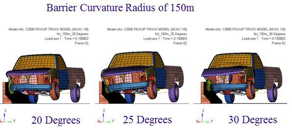
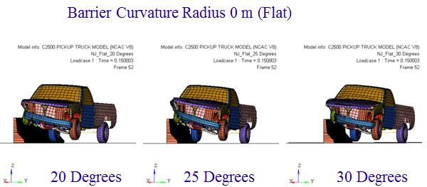
29 3.3.3 Vertical Wall Barrier A typical flat barrier is shown in Figure 3.5. The typical height of the barrier is 45 inches with the width being same from top to bottom. Figure 3.5 Vertical Wall Barrier 3.4 Curvature of the Road Depending on the type of the road, the era it was built and to design standards available, the curvature of the roads varies. From the regularly available road curvatures the critical angle of curvature, the analysis has been conducted. Three curvatures of 75 m radius, 150 m radius and tangent roads have been considered for the analysis. Figure 3.6 shows the three types of curvatures considered. Figure 3.6 Roadside Barrier Curvature Models (Flat, 75m Radius, 150m Radius) 18

30 3.5 Impact Angle The impact angle is a crucial factor in determining the impact behavior of the vehicle in a crash situation. The impact angle of the vehicle onto the barrier depends on many situations. The curvature of the road, the speed at which the vehicle was travelling when the turn was made, sizes of the vehicle etc., affect the angle at which the vehicle is contacts the barrier. Literature review has indicated that 25 degrees is a common angle of impact for many crash accidents. Hence, to study further varying impact angles, three impact angles of 20, 25 and 30 degrees have been considered for the analysis. Figure 3.7 shows vehicle impacting at three different angles onto the barrier. Figure 3.7 Vehicle Impact at Different Angles 19
31 3.6 Impact Velocity of the Vehicle The regular speed at which the vehicles commute on the freeways is typically around 60 mph. The studies have shown that an average speed at which most number of accidents happens is at 62 mph (100 kmph). The manual for assessment of safety hardware does not mention any other velocity as critical for analysis other than 62 mph. Initially the plan was to study the impact at only 62 mph. But as there is no analysis being conducted for higher velocities, two higher velocities of 77.7 mph (120 kmph) and 93 mph (150 kmph) were also included in this study. 20
32 CHAPTER FOUR 4 MODELING AND ANALYSIS As it has been already discussed in previous sections, the number of test cases will be many and the cost involved is quite high, the finite element modeling and analysis is most suitable choice available. 4.1 Modeling Tools The finite element analysis involves three processing tools: Pre-Processor : HYPERMESH Solver : LS_DYNA Post-Processor : HYPERVIEW Pre-Processor: To setup an FE model, one needs to use a pre-processing mechanical tool which enables the application with all the required parameters for the proper analysis. There are many tools in the market such as PATRAN, FEMAP and HYPERMESH. The tools commonly used to the dynamic analysis are PATRAN and HYPERMESH. The tool used for the analysis in this study was HYPERMESH. HYPERMESH is a tool which eases the process of modeling the FE model for the dynamic analysis. The C-2500 pickup truck FE model generated by NCAC is imported in HYPEMESH [13]. The truck model is further developed to suit our analysis requirements. It is updated with the accelerometer to read the data of the vehicle during and after the impact onto the barrier model. 21
33 Finite Element Solver: There are many dynamic analysis solver tools in the market. A widely used tool is the LS-DYNA. It is an explicit finite element program used to analyze non-linear dynamic response of three dimensional inelastic structures. Many complex crash problems can be performed with LS-DYNA because of its automated contact analysis capabilities and error checking features. LS-DYNA is capable of performing analysis with many varieties of material models such as elastic, elasto-plastic, foam models, glass and composite models. The major advantage of LS-DYNA is its capability of explicit analysis. The finite element analysis with explicit time integration factor has many merits over the implicit. The explicit analysis performs an analysis in less time step compared to implicit [9]. When the analysis model involves many solid elements, less time step solution with explicit makes it very important. The robustness of LS-DYNA while performing analysis with fully automated contact conditions makes it a widely used tool. This capability of the tool has been validated and found to be easy to work with. The analyses such as full-car crashworthiness, occupant safety analysis with a dummy occupant FE model and broken down component analysis are found to be extremely easy to work with LS-DYNA. In a model with hundreds of components, the automated contact gives LS-DYNA a capability of solving very complex problems. There are many contact types such as single surface, surface to surface varying from deformable body to deformable and deformable body to rigid body contact solutions. This contact possibility is a widely used solution technique for all the forming and crash analysis. For forming the sheet is considered as a deformable and the die as a rigid body. Similarly in crash analysis the barriers are considered as rigid and vehicle as a deformable. 22
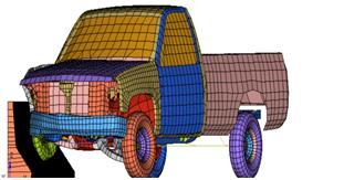
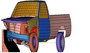
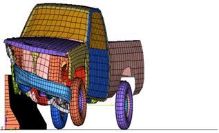
34 LS-DYNA tool is being used in many fields such as automotive, aerospace, ships and etc. In aerospace the main critical study of the bird strike is performed with much accuracy. All the interiors of aircraft are tested dynamically and are being accepted by FAA as certified models solely by FE simulation analysis. The use of finite element dummy model has spread the wings of the analysis capabilities. The metal forming problems such as extrusion, forging, casting and hydroforming can be performed with a higher accuracy. Post-Processor: Hyperview is a tool widely used for post processing the results once the problem is solved by the LS-DYNA. It is capable of performing the detailed study of the model with each time step. It is a complete post processing tool with simulation of multi body capability. It combines advanced animation with data plotting tool which enhances the result visualization. It supports many solvers in the market with flexibility and high performance. It supports multibody dynamics, complex animations and stress calculation, deformed animation, and also linear and transient animations. 4.2 Vehicle Modeling The reverse engineering techniques which recreates automotive is widely used to develop the FE model. As the models generated by this technique are more accurate, a detailed analysis with finite element dummy model to predict the occupant safety can be studied. The results can be used to make many design changes on the vehicle as well as surrounding parameters such as barriers on the road and also the design of the road. To match the full scale test condition, required by NCHRP Report 350, a widely used and accepted FE model of C2500 pick-up truck by NCAC has been used. The FE model of C2500 pick-up truck has 248 parts with elements. Figure 4.1 shows the pictorial representation of the FE model of the truck. The Table 4.1 shows finite element compositions of the truck model. 23
![The analysis has been performed by the non-linear explicit analysis tool LS-DYNA. Researchers usually apply tape on top of the vehicle to obtain an accurate representation of the geometries [10].](/docs-images/87/95050157/images/35-0.jpg "Every component is disassembled and digitized. The mass and material data is recorded with center of gravity of the entire vehicle. Table 4.")
35 The analysis has been performed by the non-linear explicit analysis tool LS-DYNA. Researchers usually apply tape on top of the vehicle to obtain an accurate representation of the geometries [10]. Every component is disassembled and digitized. The mass and material data is recorded with center of gravity of the entire vehicle. Table 4.1 Vehicle Model Summary Vehicle Model Summary Parts 248 Nodes Elements Mass (lbs) 2700 Figure 4.1 Chevrolet C2500 FE model Table 4.2 Material Properties Mass Density 7890 kg/m 3 Young's Modulus 210E+09 N/mm 2 270E+09 Yield Stress N/mm 2 Poisson's ratio

36 An elasto-plastic material model is used with material properties as defined in Table 4.2. For most of the automotive material models and also for aerospace models, the MAT_PIECEWISE_LINEAR_PLASTICITY material model from LS-DYNA is used. This material is used for all steel and aluminum material parts. The entire chassis, drive train and suspension are made up for steel. For most of the other parts and rims the aluminum material is used. This material model is an elasto-plastic material with defined stress and strain curve. The rubber, motor mounts, transmission mounts and the beam elements are modeled using MAT_ELASTIC material card. This being an isotropic elastic material is available for beam, shell and solid element models. 4.3 Barrier Modeling The barrier model with required design is modeled and meshed with proper constraints. As the barrier model in actual practice experiences a very little damage during the crash, for the sake of simplifying the analysis, the barriers are designed to be a rigid body. The ends of the barrier model are constrained in all degrees of freedom. Figure 4.2 shows the constraints for the barrier. Figure 4.2 Barrier Constraints with all DOF 25

37 The barrier FE models for the NJ, F-shaped and flat are shown in Figure 4.3. As the concrete barriers deployed on the highways hardly get damaged during an impact crash, the barriers are considered as rigid in this study, thus making the crash analysis a worst case condition as no energy is absorbed by the barrier, and all needs to be dissipated by vehicle itself. Figure 4.3 Barrier FE models The shape of the barrier designs is a critical criterion in the crash analysis. A slight change in the slope of the barrier will affect a lot in the vehicle roll and lift [2]. All the barriers have been modeled as per the dimensions mentioned in Section 3.1 of this report. As the barriers have been represented as a rigid blocks, the friction between the barrier and the floor has been neglected. The study on impact of friction between the road and the barrier has been studied [11]. The coefficient of friction of 0.3 is found to be a suitable value for model validation. A higher friction value will result in a stiffer model and will increase the intrusion of the vehicle into the barrier. The simulation was found to be accurately matching the test results with a value of 0.3 for the friction coefficient. 26
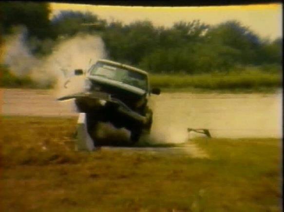
38 CHAPTER FIVE 5 MODEL VALIDATION AND PARAMETRIC DESIGN STUDY 5.1 Model Validation The first step in the analysis is to have an analysis model which is validated enough to show a good comparison to that of the test results. Hence, a detailed model validation study was conducted for model validation or verification, and to have a validated model for further parametric analysis. To make sure that the dynamic simulation tools being used are generating a reasonable result, a mode validation run was generated and a comparison of simulation plots with those of the tests by Mak [2] was performed. Figure 5.1 and Figure 5.2 show a comparison of views for simulation and test at different time frames with front and top views. A C2500 pick-up truck was made to impact onto a New- Jersey barrier model at a velocity of 62 mph at an impact angle of 25 degrees. The barrier was considered to be a rigid body, making the study a more critical (or worst-case) analysis. The visual inspection of the comparison shows a significant amount of similarity in the simulation model and test run. In Figure 5.3, the pitch, roll and yaw for simulation have been shown. There is a reasonable similarity between the simulation values to that of test shown in Figure 5.3. The Figure 5.4 is from NCAC study [1], which is used to compare the simulation values to that of test. Hence further analysis was conducted with this correlated FE model to study dynamic impact behaviors with different design of barriers and different impact curvatures. 27


39 t = t = t = 0.12 t = 0.15 Figure 5.1 Simulation (from this Study) and Test Model (from [1]) Comparison (Front View) 28
![t = 0.024 t = 0.084 t = 0.12 t = 0.15 Figure 5.2 Simulation (from this Study) and Test Model (from [1]) Comparison (Top View) The FE simulation comparison with that of the test from Figure 3.8 and 3.](/docs-images/87/95050157/images/40-0.jpg "9 show a reasonably good correlation. The comparisons have been made at different time steps to show the exact behavior of the vehicle.")
40 t = t = t = 0.12 t = 0.15 Figure 5.2 Simulation (from this Study) and Test Model (from [1]) Comparison (Top View) The FE simulation comparison with that of the test from Figure 3.8 and 3.9 show a reasonably good correlation. The comparisons have been made at different time steps to show the exact behavior of the vehicle. The vehicle lift and the intrusion into the barrier are seen to be reasonably matching the test results. The vehicle rotation from the top is also seen to be reasonably matching the test result. 29


41 Figure 5.3 Simulation and Test Model Roll, Pitch and Yaw Comparison (from this study) Figure 5.4 Roll, Pitch and Yaw Comparison from NCAC 2011-W-005 [1] The roll, pitch and yaw for the CG point of the vehicle are shown in the Figure 5.3. These values are compared to those of the test results which are shown in Figure 5.4. A reasonable amount of correlation has been found between FE and test values. 30
 Acceleration,")
42 5.2 Parametric Study The analysis was then performed for three different barriers designs, with three different road curvatures, and at three different impact angles. These set of combinations were tested for following five output sets: Vehicle Lift, Vehicle Roll Angle, Occupant Ride-Down Acceleration, Occupant Impact Velocity, Roll (Angular) Acceleration, Intrusion and Penetration of the Truck. Vehicle Lift: Vehicle lift is the maximum height reached by the front wheel node after the impact, as shown in Figure 5.5. This can be analyzed and shown that for which barrier design, the lift is higher and will have a more possibility of vaulting the barrier. Figure 5.5 Vehicle Lift Node 31

43 Vehicle Roll Angle: The vehicle roll angle is plotted from the center of gravity point of the vehicle. It is the point about which the vehicle rotates and as the roll angle goes higher the possibility of the vehicle toppling will be more. The CG of the vehicle is shown in Figure 5.6. Figure 5.6 Center of Gravity point of the Vehicle Occupant Ride-Down Acceleration (ORA): As defined by the NCHRP report 350, the vehicle occupant ride down acceleration (ORA) is the maximum acceleration experienced by the occupant. The ORA value of 15 g s and 20 g s is considered to be detrimental for the occupant safety. The ORA is also plotted from the CG node of the vehicle as shown in Figure 5.6. The CG data is a critical factor for the vehicle as most of the impact depends on this. The possibility of the vehicle vaulting, rolling or toppling will depend on how the vehicle is balanced. Also the road and climatic conditions matter for all these parameters. 32
44 Occupant Impact Velocity (OIV): The maximum velocity experienced by the occupant should be about 9 m/s. If the velocity increases to 12 m/s, then it could be dangerous for the occupant. The OIV is also plotted from the CG node of the vehicle. Roll (Angular) Acceleration: It is the rotational acceleration experienced by the occupant after the impact. It is evaluated for the CG point of the vehicle. This can be a critical factor in defining the toppling of the vehicle. A smaller difference in angular acceleration could result in higher impact on the occupant and could result in serious injuries. The roll acceleration is approximated as per Figure 5.7. Where, α = Roll Acceleration Awy = Tangential Acceleration at wheel Agy = Tangential Acceleration at CG L = Distance from wheels to CG Figure 5.7 Roll Acceleration Intrusion and Penetration of the Truck: The intrusion and penetration into the cabin of the truck is a quite serious factor as this may cause major injuries to the occupant. If the vehicle penetrates into the barrier, the possibility of the occupant compressing and impacting with cabin interior will be higher which will result in 33
45 suppression of the occupant within the cabin region. This will result in possibility of occupant not being able to escape from the vehicle after the vehicle impact and the vehicle as come to rest. 5.3 Results and Discussions Though the analysis was run for three different velocities, only 62.5 mph velocity data was used to analyze the barrier design performance. The vehicle behavior after crash was studied by comparing lift data at three different velocities. The vehicle lift results at three different velocities are discussed in detail in section 5.3. A series of analyses were run for three different barrier designs at three different impact angles which are on three different road curvatures. These 27 combinations of runs were analyzed and the result has been tabulated in Table 5.1 thru Table 5.3. Table 5.1 Summary of Performance of New - Jersey Barrier Velocity kmph (mph) 100 (62.5) Impact Angle Curvature (Radius) Lift (mm) Roll (Degree) New - Jersey Barrier ORA (mm/sec 2 ) OIV (mm/s) Angular Acceleration (rad/sec 2 ) 75m m Flat m m Flat m m Flat
46 Table 5.2 Summary of Performance of F-Shape Barrier Velocity kmph (mph) 100 (62.5) Impact Angle Curvature (Radius) Lift (mm) Roll (Degree) F-Shape Barrier ORA (mm/sec 2 ) OIV (mm/s) Angular Acceleration (rad/sec2) 75m m Flat m m Flat m m Flat Table 5.3 Summary of Performance of Vertical Wall Barrier Velocity kmph (mph) 100 (62.5) Impact Angle Curvature (Radius) Lift (mm) Roll (Degree) Vertical Wall Barrier ORA (mm/sec 2 ) OIV (mm/s) Angular Acceleration (rad/sec2) 75m m Flat m m Flat m m Flat

47 Figure 5.8 Vehicle Lift for New Jersey Barrier Figure 5.9 Vehicle Impact onto New Jersey Barrier with 75m Radius Table 5.1 thru Table 5.3, the vehicle behavior on different barrier designs at different impact angles is shown. Figure 5.8 shows a sample of results for New Jersey barrier. Figure 5.9 shows the vehicle impacting on 75m radius New Jersey barrier model. The impact is shown at initial, middle and final time steps. The detailed plots for all the barriers are included in the Appendix of this document. Table 5.1 thru Table 5.3, it is evident that the New-Jersey barrier design is the more critical than the other two designs. The lift for the flat New Jersey barrier is found to be 580 mm compared to 450mm and 52 mm for F-shape and vertical wall barriers. It can be stated that the slope on the face of the barrier is of a major factor in defining the lift of the vehicle. 36

48 From the summary table, the vehicle lift has been plotted against the impact angle conditions for all the barrier designs. Figure 5.10 it indicates that the New-Jersey barrier, due to its slope on the face, produces maximum lift. Also it is seen that as the impact angle increases, the lift of the vehicle also increases. Figure 5.10 Vehicle Lift vs. Impact Angle As the lift of the vehicle increases, the possibility of the vehicle roll reduces. The vehicle lift can elevate the possibility of vehicle vaulting the barrier and crossing the road and entering the other side traffic. The roll can make the vehicle to topple upside down. Form the summary table, it can be seen that the vertical wall barrier has the highest roll angle increasing the possibility of toppling. Figure 5.11 shows the roll of the vehicle plotted against the impact angles for all the barrier designs. For impact angle of 20 degrees, vertical wall produces highest roll. As the impact angle increases, the New Jersey barrier produces maximum vehicle roll. 37

49 . Figure 5.11 Vehicle Roll Vs. Impact Angle Figure 5.12 shows the comparison of occupant ride-down acceleration plotted against the impact angles. Clearly the acceleration experienced by the occupant is higher for New Jersey barrier design. This is because of high lift of the vehicle due to its slope on the face. The vehicle lifts up increasing the acceleration experienced by the occupant. Similarly the high lift causes high impact velocity of the occupant as shown in Figure It is clear with all these factors that the slope on the face of the barrier makes the vehicle lift up and stops from vaulting the barrier and entering the other side traffic. 38

50 Figure 5.12 Occupant Ride-Down Acceleration Vs. Impact Angle Figure 5.13 Occupant Impact Velocity Vs Impact Angle 39

51 Figure 5.14 Angular Acceleration Vs Impact Angle Figure 5.15 Vehicle Penetrations into the Barrier 40
52 Figure 5.15 shows the amount of vehicle penetration into the barrier model. From Figure 5.15, it is clear that the penetration of the vehicle is higher for the vertical wall barrier. The lift of the vehicle makes the vehicle stay in the same traffic and not vault the barrier and enter the other side traffic avoiding the serious crash situations. Also from the vehicle penetration, it is observed that the compression of cabin is less, hence avoiding serious injury to the occupant. Overall, it can be stated that the New Jersey barrier design model will reduce the possibility of injury to the occupant. The occupant will be crushed less inside the cabin compared to the vertical wall and F-shape barriers. The vehicle will still remain in the same side of the traffic avoiding the serious injury. 5.4 Design of Experiments (DOE) It is evident from the parametric analysis that the New Jersey barrier model is the preferred design which reduces possibilities of serious injuries to the occupant. Based on Table 5.1 thru Table 5.3, a study of Analysis of Variance (ANOVA) was performed on all three barrier designs to study only lift of the vehicle. This study was intended to analyze the effect of the curvature of the road on the lift of the vehicle. Figure 5.16 shows the ANOVA output for the New Jersey barrier. It can be seen that the Flat road curvature generates the highest lift. As the P-value is less than the Alpha (0.05), the null hypothesis of there is no significant difference between the mean values is rejected. It can then be concluded that there is a significant difference between the mean values and, that the road curvature does matter for the lift of the vehicle. 41


53 Figure 5.16 ANOVA for New Jersey Barrier Figure 5.17 ANOVA for F-Shape Barrier 42
54 Figure 5.18 ANOVA for Vertical Wall Barrier Similarly from the Figure 5.17, it can be concluded that the flat road curvature generates highest lift. This can be detrimental for the occupant as the lift reduces, the possibility of the vehicle vaulting the barrier increases. This leads the vehicle to enter the other side traffic or jump off the bridge. Hence, there is a necessity for redesigning of the barriers for the curved road conditions. 5.5 Effect of Input Velocity As the Manual for Assessment of Safety Hardware (MASH) and NCHRP Report 350 does not mention the requirement for study of impact of different velocity on the vehicle crash, there was a necessity to address this question. As it has been already concluded that the New Jersey barrier is a highly used barrier and a critical one, the same was tested for different velocities. Table 5.4 summarizes the vehicle lift for three impact velocities on New Jersey barrier 43

55 model. It is evident that the lift will increase as the increase in velocity. Figure 5.19 shows a bar chart comparing the lift of the vehicle at three different velocities. Table 5.4 Effect of Velocity on vehicle Lift Vehicle Lift - mm Effect of Velocity on Vehicle Lift Impact Angle - Degree 100 kmph 125 kmph 150 kmph Figure 5.19 Velocity vs. Vehicle Lift 44
56 CHAPTER SIX 6 CONCLUSIONS AND FUTURE WORK 6.1 Conclusions Effort has been made in this thesis to study the effects of vehicle crash dynamics on three different barrier designs, at three different road curvatures, and at three different impact angles. The barriers designs considered were the designs, which are widely used on the highways currently. Literature reviews indicated that the study with respect to the road curvature had not been of the primary concern for the researchers, an effort to study the same was made. Three different barrier designs were used with three impact angles for three different curvatures were utilized for impact analysis of vehicle model at different impact velocities. The primary model was first validated with the results from experimental test available in literature. The parametric study was subsequently conducted with output values for barrier design, impact angle and curvatures. From the range of analysis conducted in this study, it can be concluded that the New-Jersey barrier has the highest lift, occupant ride-down and also occupant impact velocity compared to the F-Shape and the Vertical wall designs. Hence, the New Jersey barrier design will ensure that the vehicle does not vault the barrier and enter the other side of the traffic elevating the possibility of higher risks. The reduction in the possibility of vaulting the barrier will also avoid the vehicle from jumping off the bridge. From the study, it has also been found that the impact angle is a more critical factor than the road curvature. Deploying the proper barrier designs depending on the road curvature will avoid major risks to the occupant. The statistical ANOVA study also indicated the similar results. 45
57 The vehicle lift increases as the slope on the barrier increases. Lift, vehicle ride down acceleration, and occupant impact velocity were also found to be less for the vertical wall barrier. The lift of the vehicle will increase the occupant acceleration. The roll angle, being less for the New Jersey barrier, makes it less vulnerable for the toppling of the vehicle. The angular acceleration is also highest for the New Jersey barrier. It was also observed that the vehicle penetration is least for New Jersey barrier compared to vertical wall. The vehicle is crushed least in the front of the vehicle which makes the cabin to compress less inside. This drastically reduces the possibility of occupant being impacted inside the cabin. Hence, the lift of the vehicle due to the slope on the face of the barrier reduces the possibility of cabin crushing. Overall, based on the results from this study, the New Jersey-type barrier is recommended to be utilized on the roads, and the road curvature to be at least 75m. 6.2 Recommendations for Future Work There is always a chance for improvement in the safety of the occupant. The analysis performed here does not consider the impact angle more than 30 degrees. The study of this condition can give a clearer understanding of the barrier designs. The actuall occupant multibody FE models was not considered in this study. Including the occupant model will assist in analysing the injury measure such as the Head Injury Critria(HIC) for the occupants. This will also help in analysing the impact of lift of the vehicle on the occupant. As mentioned earlier, the frictional componant between the road and the barrier has been neglected in this analysis. The barrier has been considered as a rigid body. Modeling the barrier as a deformable and including the frictional componant between the barrier and the road will enhance the capability of the predicting the dynamic behavior of the vehicle more accurately. 46
58 The study of intrusion of front of the vehicle back into the cabin of the vechile will be critical as this increases the criticality of the injury to the occupant. This depends on the rubustness of the vehicle design and varies from one vehicle model to another. 47
59 REFERENCES 48
60 REFERENCES [1] Marzougi, D, Kan, C. D., and Opiela, K. S. Safety Evaluation of Concrete Barriers on Curved and Superlevated Roads, NCAC 2011-W-005, January [2] Ross, H.E, Sicking, D.L., Zimmer, R.A., Recommended Procedures for the Safety Performance Evaluation of Highway Features, NCHRP Report 350, Transportation Research Board, Washington, DC, [3] Neissner., C. W. Evaluation of Existing Roadside Safety Hardware Using Manual for Assessing Safety Hardware (MASH) Criteria, NCHRP, Research Results Digest 349, August [4] American Association of State Highway and Transportation Official, Manual for Assessing Safety Hardware, [5] Esfahani., E. S, Marzougi, D and Opiela, K. S. Safety Performance of Concrete Median Barriers under Updated Crashworthiness Criteria NCAC 2008-W-002, October [6] Consolazio., R. G., and Chung., H. J, Vehicle Impact Simulation for Curb and Barrier Design, Volume 1 Impact Simulation Techniques, New Jersey Department of Transportation, October [7] Ensco, Inc., Traffic Barriers on Curves, Curbs and Slopes, Final report Prepared for FHWA, [8] Marzougi., D., and Buyuk., M., Performance Evaluation of Portable Concrete barriers NCAC, [9] LS-DYNA User s Manual, version 971, Livermore Software Technology Corporation, [10] National Crash Analysis Center (NCAC), May [11] Marzougi., D., Evaluation of Portable Concrete Barriers Using FE Simulation, NCAC [12] Hallquist, J. O., LSDYNA Theorotical Manual, Livermore Software Technology Corporation,
61 [13] Marzougui, D., Zaouk, and Kan, C.D, Development of a C-2500 Pickup Truck Model for Roadside Hardware Impact. TRBA Conference,
62 APPENDIX 51

 Barrier")
63 APPENDIX SIMULATIONS OUTPUT Lift of the Vehicle New Jersey Shape Barrier Lift of the Vehicle - F-Shape Barrier Lift of the Vehicle Vertical wall (Flat) Barrier 52


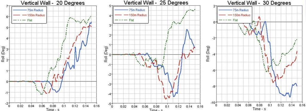
64 Roll of the Vehicle New Jersey Shape Barrier Roll of the Vehicle - F-Shape Barrier Roll of the Vehicle Vertical wall (Flat) Barrier 53

")
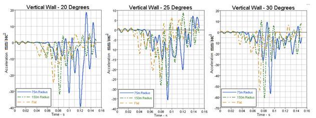
65 Vehicle Ride-Down Acceleration New Jersey Shape Barrier Vehicle Ride-Down Acceleration - F-Shape Barrier Vehicle Ride-Down Acceleration Vertical wall (Flat) Barrier 54

")
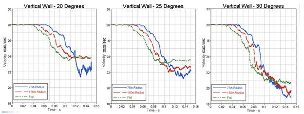
66 Occupant Impact Velocity New Jersey Shape Barrier Occupant Impact Velocity - F-Shape Barrier Occupant Impact Velocity Vertical wall (Flat) Barrier 55
67 56
Development and Validation of a Finite Element Model of an Energy-absorbing Guardrail End Terminal
 Development and Validation of a Finite Element Model of an Energy-absorbing Guardrail End Terminal Yunzhu Meng 1, Costin Untaroiu 1 1 Department of Biomedical Engineering and Virginia Tech, Blacksburg,
Design Evaluation of Fuel Tank & Chassis Frame for Rear Impact of Toyota Yaris
 International Research Journal of Engineering and Technology (IRJET) e-issn: 2395-0056 Volume: 03 Issue: 05 May-2016 p-issn: 2395-0072 www.irjet.net Design Evaluation of Fuel Tank & Chassis Frame for Rear
Crashworthiness Evaluation of an Impact Energy Absorber in a Car Bumper for Frontal Crash Event - A FEA Approach
 Crashworthiness Evaluation of an Impact Energy Absorber in a Car Bumper for Frontal Crash Event - A FEA Approach Pravin E. Fulpagar, Dr.S.P.Shekhawat Department of Mechanical Engineering, SSBTS COET Jalgaon.
FINITE ELEMENT METHOD IN CAR COMPATIBILITY PHENOMENA
 Journal of KONES Powertrain and Transport, Vol. 18, No. 4 2011 FINITE ELEMENT METHOD IN CAR COMPATIBILITY PHENOMENA Marcin Lisiecki Technical University of Warsaw Faculty of Power and Aeronautical Engineering
Development of a Finite Element Model of a Motorcycle
 Development of a Finite Element Model of a Motorcycle N. Schulz, C. Silvestri Dobrovolny and S. Hurlebaus Texas A&M Transportation Institute Abstract Over the past years, extensive research efforts have
Methodologies and Examples for Efficient Short and Long Duration Integrated Occupant-Vehicle Crash Simulation
 13 th International LS-DYNA Users Conference Session: Automotive Methodologies and Examples for Efficient Short and Long Duration Integrated Occupant-Vehicle Crash Simulation R. Reichert, C.-D. Kan, D.
FE Modeling and Analysis of a Human powered/electric Tricycle chassis
 FE Modeling and Analysis of a Human powered/electric Tricycle chassis Sahil Kakria B.Tech, Mechanical Engg UCOE, Punjabi University Patiala, Punjab-147004 kakria.sahil@gmail.com Abbreviations: SAE- Society
Manual for Assessing Safety Hardware
 American Association of State Highway and Transportation Officials Manual for Assessing Safety Hardware 2009 vii PREFACE Effective traffic barrier systems, end treatments, crash cushions, breakaway devices,
Advances in Simulating Corrugated Beam Barriers under Vehicular Impact
 13 th International LS-DYNA Users Conference Session: Automotive Advances in Simulating Corrugated Beam Barriers under Vehicular Impact Akram Abu-Odeh Texas A&M Transportation Institute Abstract W-beam
VERTICAL IMPACT SIMULATIONS OF A FULL-SIZE AND SIMPLIFIED SCALED MODELS OF AN AIRCRAFT FUSELAGE SECTION
 VERTICAL IMPACT SIMULATIONS OF A FULL-SIZE AND SIMPLIFIED SCALED MODELS OF AN AIRCRAFT FUSELAGE SECTION A Thesis by Vishal Krishna Prasad Bachelor of Engineering, Visvesvaraya Technological University,
Simulating Rotary Draw Bending and Tube Hydroforming
 Abstract: Simulating Rotary Draw Bending and Tube Hydroforming Dilip K Mahanty, Narendran M. Balan Engineering Services Group, Tata Consultancy Services Tube hydroforming is currently an active area of
Working Paper. Development and Validation of a Pick-Up Truck Suspension Finite Element Model for Use in Crash Simulation
 Working Paper NCAC 2003-W-003 October 2003 Development and Validation of a Pick-Up Truck Suspension Finite Element Model for Use in Crash Simulation Dhafer Marzougui Cing-Dao (Steve) Kan Matthias Zink
MODELING SUSPENSION DAMPER MODULES USING LS-DYNA
 MODELING SUSPENSION DAMPER MODULES USING LS-DYNA Jason J. Tao Delphi Automotive Systems Energy & Chassis Systems Division 435 Cincinnati Street Dayton, OH 4548 Telephone: (937) 455-6298 E-mail: Jason.J.Tao@Delphiauto.com
EFFECTIVENESS OF COUNTERMEASURES IN RESPONSE TO FMVSS 201 UPPER INTERIOR HEAD IMPACT PROTECTION
 EFFECTIVENESS OF COUNTERMEASURES IN RESPONSE TO FMVSS 201 UPPER INTERIOR HEAD IMPACT PROTECTION Arun Chickmenahalli Lear Corporation Michigan, USA Tel: 248-447-7771 Fax: 248-447-1512 E-mail: achickmenahalli@lear.com
NUMERICAL ANALYSIS OF IMPACT BETWEEN SHUNTING LOCOMOTIVE AND SELECTED ROAD VEHICLE
 Journal of KONES Powertrain and Transport, Vol. 21, No. 4 2014 ISSN: 1231-4005 e-issn: 2354-0133 ICID: 1130437 DOI: 10.5604/12314005.1130437 NUMERICAL ANALYSIS OF IMPACT BETWEEN SHUNTING LOCOMOTIVE AND
Vehicle Dynamic Simulation Using A Non-Linear Finite Element Simulation Program (LS-DYNA)
") Vehicle Dynamic Simulation Using A Non-Linear Finite Element Simulation Program (LS-DYNA) G. S. Choi and H. K. Min Kia Motors Technical Center 3-61 INTRODUCTION The reason manufacturers invest their time
Vehicle Dynamic Simulation Using A Non-Linear Finite Element Simulation Program (LS-DYNA) G. S. Choi and H. K. Min Kia Motors Technical Center 3-61 INTRODUCTION The reason manufacturers invest their time
Assessing Options for Improving Roadside Barrier Crashworthiness
 13 th International LS-DYNA Users Conference Session: Simulation Assessing Options for Improving Roadside Barrier Crashworthiness D. Marzougui, C.D. Kan, and K.S. Opiela Center for Collision Safety and
Chapter 7: Thermal Study of Transmission Gearbox
 Chapter 7: Thermal Study of Transmission Gearbox 7.1 Introduction The main objective of this chapter is to investigate the performance of automobile transmission gearbox under the influence of load, rotational
Simulation and Validation of FMVSS 207/210 Using LS-DYNA
 7 th International LS-DYNA Users Conference Simulation Technology (2) Simulation and Validation of FMVSS 207/210 Using LS-DYNA Vikas Patwardhan Tuhin Halder Frank Xu Babushankar Sambamoorthy Lear Corporation
VERIFICATION & VALIDATION REPORT of MGS Barrier Impact with 1100C Vehicle Using Toyota Yaris Coarse FE Model
 VERIFICATION & VALIDATION REPORT of MGS Barrier Impact with 1100C Vehicle Using Toyota Yaris Coarse FE Model CCSA VALIDATION/VERIFICATION REPORT Page 1 of 4 Project: CCSA Longitudinal Barriers on Curved,
Design Improvement in front Bumper of a Passenger Car using Impact Analysis
 Design Improvement in front Bumper of a Passenger Car using Impact Analysis P. Sridhar *1,Dr. R.S Uma Maheswar Rao 2,Mr. Y Vijaya Kumar 3 *1,2,3 Department of Mechanical Engineering, JB Institute of Engineering
Simulation of Structural Latches in an Automotive Seat System Using LS-DYNA
 Simulation of Structural Latches in an Automotive Seat System Using LS-DYNA Tuhin Halder Lear Corporation, U152 Group 5200, Auto Club Drive Dearborn, MI 48126 USA. + 313 845 0492 thalder@ford.com Keywords:
ROOF CRUSH SIMULATION OF PASSENGER CAR FOR IMPROVING OCCUPANT SAFETY IN CABIN
 ROOF CRUSH SIMULATION OF PASSENGER CAR FOR IMPROVING OCCUPANT SAFETY IN CABIN Anandkumar. M. Padashetti M.Tech student (Design Engineering), Mechanical Engineering, K L E Dr. M S Sheshagiri College of
KINEMATICAL SUSPENSION OPTIMIZATION USING DESIGN OF EXPERIMENT METHOD
 Jurnal Mekanikal June 2014, No 37, 16-25 KINEMATICAL SUSPENSION OPTIMIZATION USING DESIGN OF EXPERIMENT METHOD Mohd Awaluddin A Rahman and Afandi Dzakaria Faculty of Mechanical Engineering, Universiti
November 16, 1998 Refer to: HNG-14. Mr. David Allardyce Mechanical Engineer B&B Electromatic Main Street Norwood, Louisiana 70761
 November 16, 1998 Refer to: HNG-14 Mr. David Allardyce Mechanical Engineer B&B Electromatic 14113 Main Street Norwood, Louisiana 70761 Dear Mr. Allardyce: In your August 31 letter, you presented some preliminary
Crashworthiness of an Electric Prototype Vehicle Series
 Crashworthiness of an Electric Prototype Vehicle Series Schluckspecht Project Collaboration for Crashworthiness F. Huberth *, S. Sinz *+, S. Herb *+, J. Lienhard *+, M. Jung *, K. Thoma *, K. Hochberg
Automotive Seat Modeling and Simulation for Occupant Safety using Dynamic Sled Testing
 Automotive Seat Modeling and Simulation for Occupant Safety using Dynamic Sled Testing Dr. Vikrama Singh Professor Mech. Engineering Dept.Pad.Dr.D.Y.Patil Institute of Engineering & Tech.Pimpri Pune Mr.
126 Ridge Road Tel: (607) PO Box 187 Fax: (607)
 PO Box 187 Fax: (607)") 1. Summary Finite element modeling has been used to determine deflections and stress levels within the SRC planar undulator. Of principal concern is the shift in the magnetic centerline and the rotation
1. Summary Finite element modeling has been used to determine deflections and stress levels within the SRC planar undulator. Of principal concern is the shift in the magnetic centerline and the rotation
Vehicle Seat Bottom Cushion Clip Force Study for FMVSS No. 207 Requirements
 14 th International LS-DYNA Users Conference Session: Automotive Vehicle Seat Bottom Cushion Clip Force Study for FMVSS No. 207 Requirements Jaehyuk Jang CAE Body Structure Systems General Motors Abstract
An Analysis of Less Hazardous Roadside Signposts. By Andrei Lozzi & Paul Briozzo Dept of Mechanical & Mechatronic Engineering University of Sydney
 An Analysis of Less Hazardous Roadside Signposts By Andrei Lozzi & Paul Briozzo Dept of Mechanical & Mechatronic Engineering University of Sydney 1 Abstract This work arrives at an overview of requirements
VULCAN BARRIER TL-3 GENERAL SPECIFICATIONS
 VULCAN BARRIER TL-3 GENERAL SPECIFICATIONS I. GENERAL A. The VULCAN BARRIER TL-3 (VULCAN TL-3) shall be a highly portable and crashworthy longitudinal barrier especially suited for use as a temporary barrier
Design and Analysis of Pressure Die Casting Die for Side Differential Cover of Mini truck
 Design and Analysis of Pressure Die Casting Die for Side Differential Cover of Mini truck 1 A Chakravarthi P.G student, Department of Mechanical Engineering,KSRM CE, kadapa-516003 2. R Rama Krishna Reddy,
Static Analysis of Crankcase and Crankshaft of Single Cylinder Four Stroke Diesel Engine
 Static Analysis of Crankcase and Crankshaft of Single Cylinder Four Stroke Diesel Engine Kakade Pratik 1 Post Graduate Student kakadepratik@gmail.com Pasarkar M. D. 2 Assistant Professor mdpasarkar@gmail.com
Effectiveness of ECP Brakes in Reducing the Risks Associated with HHFT Trains
 Effectiveness of ECP Brakes in Reducing the Risks Associated with HHFT Trains Presented To The National Academy of Sciences Review Committee October 14, 2016 Slide 1 1 Agenda Background leading to HM-251
VULCAN BARRIER TL-3 GENERAL SPECIFICATIONS
 VULCAN BARRIER TL-3 GENERAL SPECIFICATIONS I. GENERAL A. The VULCAN BARRIER TL-3 (VULCAN TL-3) shall be a highly portable and crashworthy longitudinal barrier especially suited for use as a temporary barrier
ROBUST PROJECT Norwegian Public Roads Administration / Force Technology Norway AS
 ROBUST PROJECT Norwegian Public Roads Administration / Force Technology Norway AS Evaluation of small car - RM_R1 - prepared by Politecnico di Milano Volume 1 of 1 January 2006 Doc. No.: ROBUST-5-002/TR-2004-0039
WP5 - Computational Mechanics B5 - Temporary Vertical Concrete Safety Barrier MAIN REPORT Volume 1 of 1
 ROBUST PROJECT TRL Limited WP5 - Computational Mechanics B5 - Temporary Vertical Concrete Safety Barrier MAIN REPORT Volume 1 of 1 December 2005 Doc. No.: ROBUST-5-010c Rev. 0. (Logo here) Main Report
June 5, In Reply Refer To: HSSD/B-178. Mr. Kevin K. Groeneweg Mobile Barriers LLC Genesee Trail Road Golden, CO Dear Mr.
 June 5, 2008 1200 New Jersey Avenue, SE. Washington, DC 20590 In Reply Refer To: HSSD/B-178 Mr. Kevin K. Groeneweg Mobile Barriers LLC 24918 Genesee Trail Road Golden, CO 80401 Dear Mr. Groeneweg: This
Gasket Simulations process considering design parameters
 Gasket Simulations process considering design parameters Sonu Paroche Deputy Manager VE Commercial Vehicles Ltd. 102, Industrial Area No. 1 Pithampur, District Dhar MP - 454775, India sparoche@vecv.in
Finite Element Modeling and Analysis of Vehicle Space Frame with Experimental Validation
 Finite Element Modeling and Analysis of Vehicle Space Frame with Experimental Validation Assoc. Prof Dr. Mohammed A.Elhaddad Mechanical Engineering Department Higher Technological Institute, Town of 6
VEHICLE ANTI-ROLL BAR ANALYZED USING FEA TOOL ANSYS
 VEHICLE ANTI-ROLL BAR ANALYZED USING FEA TOOL ANSYS P. M. Bora 1, Dr. P. K. Sharma 2 1 M. Tech. Student,NIIST, Bhopal(India) 2 Professor & HOD,NIIST, Bhopal(India) ABSTRACT The aim of this paper is to
VIBRATION REDUCTION IN CONVENTIONAL VEHICLES BY INCREASING THE STIFFNESS ON THE CHASSIS FRAME
 VIBRATION REDUCTION IN CONVENTIONAL VEHICLES BY INCREASING THE STIFFNESS ON THE CHASSIS FRAME S. Ganesan and K. Panneerselvam Sathyabama University, Chennai, India E-Mail: ganesuma@gmail.com ABSTRACT The
Full Vehicle Durability Prediction Using Co-simulation Between Implicit & Explicit Finite Element Solvers
 Full Vehicle Durability Prediction Using Co-simulation Between Implicit & Explicit Finite Element Solvers SIMULIA Great Lakes Regional User Meeting Oct 12, 2011 Victor Oancea Member of SIMULIA CTO Office
Abaqus Technology Brief. Prediction of B-Pillar Failure in Automobile Bodies
 Prediction of B-Pillar Failure in Automobile Bodies Abaqus Technology Brief TB-08-BPF-1 Revised: September 2008 Summary The B-pillar is an important load carrying component of any automobile body. It is
*Friedman Research Corporation, 1508-B Ferguson Lane, Austin, TX ** Center for Injury Research, Santa Barbara, CA, 93109
 Analysis of factors affecting ambulance compartment integrity test results and their relationship to real-world impact conditions. G Mattos*, K. Friedman*, J Paver**, J Hutchinson*, K Bui* & A Jafri* *Friedman
Modal analysis of Truck Chassis Frame IJSER
 Modal analysis of Truck Chassis Frame 158 Shubham Bhise 1, Vaibhav Dabhade 1, Sujit Pagi 1, Apurvi Veldandi 1. 1 B.E. Student, Dept. of Automobile Engineering, Saraswati College of Engineering, Navi Mumbai,
Abaqus Technology Brief. Automobile Roof Crush Analysis with Abaqus
 Abaqus Technology Brief Automobile Roof Crush Analysis with Abaqus TB-06-RCA-1 Revised: April 2007. Summary The National Highway Traffic Safety Administration (NHTSA) mandates the use of certain test procedures
Frontal Crash Simulation of Vehicles Against Lighting Columns in Kuwait Using FEM
 International Journal of Traffic and Transportation Engineering 2013, 2(5): 101-105 DOI: 10.5923/j.ijtte.20130205.02 Frontal Crash Simulation of Vehicles Against Lighting Columns in Kuwait Using FEM Yehia
1962: HRCS Circular 482 one-page document, specified vehicle mass, impact speed, and approach angle for crash tests.
 1 2 3 1962: HRCS Circular 482 one-page document, specified vehicle mass, impact speed, and approach angle for crash tests. 1973: NCHRP Report 153 16-page document, based on technical input from 70+ individuals
A MASH Compliant W-Beam Median Guardrail System
 0 0 0 0 0 A MASH Compliant W-Beam Median Guardrail System By A. Y. Abu-Odeh, R. P. Bligh, W. Odell, A. Meza, and W. L. Menges Submitted: July 0, 0 Word Count:, + ( figures + tables=,000) =, words Authors:
Structural Analysis of Pick-Up Truck Chassis using Fem
 International Journal of ChemTech Research CODEN (USA): IJCRGG, ISSN: 0974-4290, ISSN(Online):2455-9555 Vol.9, No.06 pp 384-391, 2016 Structural Analysis of Pick-Up Truck Chassis using Fem Rahul.V 1 *,
Study Of Static And Frequency Responsible Analysis Of Hangers With Exhaust System
 International Journal of Advances in Scientific Research and Engineering (ijasre) ISSN: 2454-8006 [Vol. 03, Issue 5, June -2017] Study Of Static And Frequency Responsible Analysis Of Hangers With Exhaust
Crashworthiness Analysis with Abaqus
 Crashworthiness Analysis with Abaqus 2017 About this Course Course objectives This course covers: Abaqus fundamentals and input syntax General "automatic" contact modeling Element selection for crash simulation
PREDICTION OF PISTON SLAP OF IC ENGINE USING FEA BY VARYING GAS PRESSURE
 PREDICTION OF PISTON SLAP OF IC ENGINE USING FEA BY VARYING GAS PRESSURE V. S. Konnur Department of Mechanical Engineering, BLDEA s Engineering College, Bijapur, Karnataka, (India) ABSTRACT The automotive
Semi-Active Suspension for an Automobile
 Semi-Active Suspension for an Automobile Pavan Kumar.G 1 Mechanical Engineering PESIT Bangalore, India M. Sambasiva Rao 2 Mechanical Engineering PESIT Bangalore, India Abstract Handling characteristics
Static and Dynamic Strength Analysis on Rear Axle of Small Payload Off-highway Dump Trucks
 Static and Dynamic Strength Analysis on Rear Axle of Small Payload Off-highway Dump Trucks Ji-xin Wang, Guo-qiang Wang, Shi-kui Luo, Dec-heng Zhou College of Mechanical Science and Engineering, Jilin University,
Parametric study on behaviour of box girder bridges using CSi Bridge
 Parametric study on behaviour of box girder bridges using CSi Bridge Kiran Kumar Bhagwat 1, Dr. D. K. Kulkarni 2, Prateek Cholappanavar 3 1Post Graduate student, Dept. of Civil Engineering, SDMCET Dharwad,
Vibration Measurement and Noise Control in Planetary Gear Train
 Vibration Measurement and Noise Control in Planetary Gear Train A.R.Mokate 1, R.R.Navthar 2 P.G. Student, Department of Mechanical Engineering, PDVVP COE, A. Nagar, Maharashtra, India 1 Assistance Professor,
Finite Element Analysis of Rear Under-Run Protection Device (RUPD) for Impact Loading
 for Impact Loading") International Journal of Engineering Research and Development ISSN: 2278-067X, Volume 1, Issue 7 (June 2012), PP.19-26 www.ijerd.com Finite Element Analysis of Rear Under-Run Protection Device (RUPD) for
International Journal of Engineering Research and Development ISSN: 2278-067X, Volume 1, Issue 7 (June 2012), PP.19-26 www.ijerd.com Finite Element Analysis of Rear Under-Run Protection Device (RUPD) for
Application of Reverse Engineering and Impact Analysis of Motor Cycle Helmet
 Indian Journal of Science and Technology, Vol 9(34), DOI: 10.17485/ijst/2016/v9i34/100989, September 2016 ISSN (Print) : 0974-6846 ISSN (Online) : 0974-5645 Application of Reverse Engineering and Impact
Development of a Multibody Systems Model for Investigation of the Effects of Hybrid Electric Vehicle Powertrains on Vehicle Dynamics.
 Development of a Multibody Systems Model for Investigation of the Effects of Hybrid Electric Vehicle Powertrains on Vehicle Dynamics. http://dx.doi.org/10.3991/ijoe.v11i6.5033 Matthew Bastin* and R Peter
ROLLOVER CRASHWORTHINESS OF A RURAL TRANSPORT VEHICLE USING MADYMO
 ROLLOVER CRASHWORTHINESS OF A RURAL TRANSPORT VEHICLE USING MADYMO S. Mukherjee, A. Chawla, A. Nayak, D. Mohan Indian Institute of Technology, New Delhi INDIA ABSTRACT In this work a full vehicle model
ANALYSIS OF GEAR QUALITY CRITERIA AND PERFORMANCE OF CURVED FACE WIDTH SPUR GEARS
 8 FASCICLE VIII, 8 (XIV), ISSN 11-459 Paper presented at Bucharest, Romania ANALYSIS OF GEAR QUALITY CRITERIA AND PERFORMANCE OF CURVED FACE WIDTH SPUR GEARS Laurentia ANDREI 1), Gabriel ANDREI 1) T, Douglas
Explicit Simulation of Dampened Starter System using Altair Radioss
 Explicit Simulation of Dampened Starter System using Altair Radioss Siva Sankar Reddy. A Sr. Engineer CAE, PES Valeo India Private Limited Block - A. 4th Floor, TECCI Park, Old No.285, New No.173, Rajiv
Evaluation and Design of ODOT s Type 5 Guardrail with Tubular Backup
 Evaluation and Design of ODOT s Type 5 Guardrail with Tubular Backup Draft Final Report Chuck A. Plaxico, Ph.D. James C. Kennedy, Jr., Ph.D. Charles R. Miele, P.E. for the Ohio Department of Transportation
Fatigue Life Estimation of Chassis Frame FESM Bracket for Commercial Vehicle
 Fatigue Life Estimation of Chassis Frame FESM Bracket for Commercial Vehicle Shivakumar M.M 1, Nirmala L 2 ¹M-Tech Student, Dept. of Mechanical Engineering,K.S Institute of Technology, Bangalore, India
Transmission Error in Screw Compressor Rotors
 Purdue University Purdue e-pubs International Compressor Engineering Conference School of Mechanical Engineering 2008 Transmission Error in Screw Compressor Rotors Jack Sauls Trane Follow this and additional
INTRODUCTION. Research & Reviews: Journal of Engineering and Technology. Research Article
 Aircraft Fuel Manifold Design Substantiation and Additive Manufacturing Technique Assessment Using Finite Element Analysis Prasanna ND, Balasubramanya HS, Jyothilakshmi R*, J Sharana Basavaraja and Sachin
Non-Linear Implicit Analysis of Roll over Protective Structure OSHA STANDARD (PART )
") Non-Linear Implicit Analysis of Roll over Protective Structure OSHA STANDARD (PART 1928.52) Pritam Prakash Deputy Manager - R&D, CAE International Tractor Limited Jalandhar Road, Hoshiarpur Punjab 146022,
Non-Linear Implicit Analysis of Roll over Protective Structure OSHA STANDARD (PART 1928.52) Pritam Prakash Deputy Manager - R&D, CAE International Tractor Limited Jalandhar Road, Hoshiarpur Punjab 146022,
Simulation of laminated windshield in automobile crash analysis
 Simulation of laminated windshield in automobile crash analysis 1 Pavan Gorde, 3 Kiran More 1 CAE Analyst, 3 Proffesor 1 Crash analysis(cae), 1 AT Technologies Pvt Ltd, Pune, India Abstract - The objective
Master of Engineering
 STUDIES OF FAULT CURRENT LIMITERS FOR POWER SYSTEMS PROTECTION A Project Report Submitted in partial fulfilment of the requirements for the Degree of Master of Engineering In INFORMATION AND TELECOMMUNICATION
Finite Element and Experimental Validation of Stiffness Analysis of Precision Feedback Spring and Flexure Tube of Jet Pipe Electrohydraulic Servovalve
 Finite Element and Experimental Validation of Stiffness Analysis of Precision Feedback Spring and Flexure Tube of Jet Pipe Electrohydraulic Servovalve M. Singaperumal*, Somashekhar. S. Hiremath* R. Krishna
Load Analysis and Multi Body Dynamics Analysis of Connecting Rod in Single Cylinder 4 Stroke Engine
 IJSRD - International Journal for Scientific Research & Development Vol. 3, Issue 08, 2015 ISSN (online): 2321-0613 Load Analysis and Multi Body Dynamics Analysis of Connecting Rod in Single Cylinder 4
Accelerating the Development of Expandable Liner Hanger Systems using Abaqus
 Accelerating the Development of Expandable Liner Hanger Systems using Abaqus Ganesh Nanaware, Tony Foster, Leo Gomez Baker Hughes Incorporated Abstract: Developing an expandable liner hanger system for
An Evaluation of Active Knee Bolsters
 8 th International LS-DYNA Users Conference Crash/Safety (1) An Evaluation of Active Knee Bolsters Zane Z. Yang Delphi Corporation Abstract In the present paper, the impact between an active knee bolster
PR V2. Submitted by. Professor MIDWEST Vine Street (402) Submitted to
 Submitted to") FINAL REPORT PR4893118-V2 ZONE OF INTRUSION STUDY Submitted by John D. Reid, Ph.D. Professor Dean L.. Sicking, Ph.D., P.E. Professorr and MwRSF Director MIDWEST ROADSIDE SAFETY FACILITY University of Nebraska-Lincoln
FINAL REPORT PR4893118-V2 ZONE OF INTRUSION STUDY Submitted by John D. Reid, Ph.D. Professor Dean L.. Sicking, Ph.D., P.E. Professorr and MwRSF Director MIDWEST ROADSIDE SAFETY FACILITY University of Nebraska-Lincoln
Finite Element Analysis of Bus Rollover Test in Accordance with UN ECE R66 Standard
 J. Eng. Technol. Sci., Vol. 49, No. 6, 2017, 799-810 799 Finite Element Analysis of Bus Rollover Test in Accordance with UN ECE R66 Standard Satrio Wicaksono*, M. Rizka Faisal Rahman, Sandro Mihradi &
AASHTO Manual for Assessing Safety Hardware, AASHTO/FHWA Joint Implementation Plan Standing Committee on Highways September 24, 2015
 AASHTO Manual for Assessing Safety Hardware, 2015 AASHTO/FHWA Joint Implementation Plan Standing Committee on Highways September 24, 2015 Full Scale MASH Crash Tests (NCHRP 22-14(02)) Conducted several
Aluminum Gear Shift Fork with Supporting Pad for light weighting in Commercial Vehicles
 Aluminum Gear Shift Fork with Supporting Pad for light weighting in Commercial Vehicles Suresh Kumar K, Manger VE Commercial Vehicles Limited skkandreegula@vecv.in, Naveen Sukumar N, Dy.Manger VE Commercial
Structural Analysis of Student Formula Race Car Chassis
 Structural Analysis of Student Formula Race Car Chassis Arindam Ghosh 1, Rishika Saha 2, Sourav Dhali 3, Adrija Das 4, Prasid Biswas 5, Alok Kumar Dubey 6 1Assistant Professor, Dept. of Mechanical Engineering,
FINITE ELEMENT SIMULATION OF SHOT PEENING AND STRESS PEEN FORMING
 FINITE ELEMENT SIMULATION OF SHOT PEENING AND STRESS PEEN FORMING H.Y. Miao 1, C. Perron 1, M. Lévesque 2 1. Aerospace Manufacturing Technology Center, National Research Council Canada,5154 av. Decelles,
Design Analysis and Optimization of Steering Knuckle Using Numerical Methods and Design of Experiments
 Design Analysis and Optimization of Steering Knuckle Using Numerical Methods and Design of Experiments 1 Mahendra L. Shelar, 2 Prof. H. P. Khairnar 1 MTech Scholar, 2 Assistant Professor 1,2 Department
Using ABAQUS in tire development process
 Using ABAQUS in tire development process Jani K. Ojala Nokian Tyres plc., R&D/Tire Construction Abstract: Development of a new product is relatively challenging task, especially in tire business area.
DESIGN AND ANALYSIS OF TUBULAR CHASSIS OF GO-KART
 DESIGN AND ANALYSIS OF TUBULAR CHASSIS OF GO-KART Prashant Thakare 1, Rishikesh Mishra 2, Kartik Kannav 3, Nikunj Vitalkar 4, Shreyas Patil 5, Snehal Malviya 6 1 UG Students, Department of Mechanical Engineering,
SUMMARY CHANGES FOR NCHRP REPORT 350 GUIDELINES [NCHRP (02)] Keith A. Cota, Chairman Technical Committee on Roadside Safety June 14, 2007
![SUMMARY CHANGES FOR NCHRP REPORT 350 GUIDELINES [NCHRP (02)] Keith A. Cota, Chairman Technical Committee on Roadside Safety June 14, 2007](/thumbs/87/97351925.jpg "SUMMARY CHANGES FOR NCHRP REPORT 350 GUIDELINES [NCHRP (02)] Keith A. Cota, Chairman Technical Committee on Roadside Safety June 14, 2007") SUMMARY CHANGES FOR NCHRP REPORT 350 GUIDELINES [NCHRP 22-14 (02)] Keith A. Cota, Chairman Technical Committee on Roadside Safety June 14, 2007 BACKGROUND Circular 482 (1962) First full scale crash test
SUMMARY CHANGES FOR NCHRP REPORT 350 GUIDELINES [NCHRP 22-14 (02)] Keith A. Cota, Chairman Technical Committee on Roadside Safety June 14, 2007 BACKGROUND Circular 482 (1962) First full scale crash test
ABSTRACT INTRODUCTION
 SIMULATION OF TRUCK REAR UNDERRUN BARRIER IMPACT Roger Zou*, George Rechnitzer** and Raphael Grzebieta* * Department of Civil Engineering, Monash University, ** Accident Research Centre, Monash University,
EVALUATION OF MOVING PROGRESSIVE DEFORMABLE BARRIER TEST METHOD BY COMPARING CAR TO CAR CRASH TEST
 EVALUATION OF MOVING PROGRESSIVE DEFORMABLE BARRIER TEST METHOD BY COMPARING CAR TO CAR CRASH TEST Shinsuke, Shibata Azusa, Nakata Toru, Hashimoto Honda R&D Co., Ltd. Automobile R&D Center Japan Paper
AN ANALYSIS OF DRIVER S BEHAVIOR AT MERGING SECTION ON TOKYO METOPOLITAN EXPRESSWAY WITH THE VIEWPOINT OF MIXTURE AHS SYSTEM
 AN ANALYSIS OF DRIVER S BEHAVIOR AT MERGING SECTION ON TOKYO METOPOLITAN EXPRESSWAY WITH THE VIEWPOINT OF MIXTURE AHS SYSTEM Tetsuo Shimizu Department of Civil Engineering, Tokyo Institute of Technology
CHAPTER 6 MECHANICAL SHOCK TESTS ON DIP-PCB ASSEMBLY
 135 CHAPTER 6 MECHANICAL SHOCK TESTS ON DIP-PCB ASSEMBLY 6.1 INTRODUCTION Shock is often defined as a rapid transfer of energy to a mechanical system, which results in a significant increase in the stress,
Improving Roadside Safety by Computer Simulation
 A2A04:Committee on Roadside Safety Features Chairman: John F. Carney, III, Worcester Polytechnic Institute Improving Roadside Safety by Computer Simulation DEAN L. SICKING, University of Nebraska, Lincoln
INFLUENCE OF BUMPER DESIGN TO LOWER LEG IMPACT RESPONSE
 F2006SC05 INFLUENCE OF BUMPER DESIGN TO LOWER LEG IMPACT RESPONSE Svoboda Jiri*, Kuklik Martin Czech Technical University in Prague, Faculty of Mechanical Engineering, Department of Automotive and Aerospace
COMPARISON OF THE IMPACT PERFORMANCE OF THE G4(1W) AND G4(2W) GUARDRAIL SYSTEMS UNDER NCHRP REPORT 350 TEST 3-11 CONDITIONS
 AND G4(2W) GUARDRAIL SYSTEMS UNDER NCHRP REPORT 350 TEST 3-11 CONDITIONS") Paper No. 00-0525 COMPARISON OF THE IMPACT PERFORMANCE OF THE G4(1W) AND G4(2W) GUARDRAIL SYSTEMS UNDER NCHRP REPORT 350 TEST 3-11 CONDITIONS by Chuck A. Plaxico Associate Research Engineer Worcester Polytechnic
Paper No. 00-0525 COMPARISON OF THE IMPACT PERFORMANCE OF THE G4(1W) AND G4(2W) GUARDRAIL SYSTEMS UNDER NCHRP REPORT 350 TEST 3-11 CONDITIONS by Chuck A. Plaxico Associate Research Engineer Worcester Polytechnic
MODEL FREQUENCY ANALYSIS OF AUTOMOTIVE EXHAUST SYSTEM
 Research Paper ISSN 2278 ñ 0149 www.ijmerr.com Vol. 3, No. 1, January 2014 2014 IJMERR. All Rights Reserved MODEL FREQUENCY ANALYSIS OF AUTOMOTIVE EXHAUST SYSTEM D Jai Balaji 1*, P V Srihari 1 and Veeranna
Accident Reconstruction & Vehicle Data Recovery Systems and Uses
 Research Engineers, Inc. (919) 781-7730 7730 Collision Analysis Engineering Animation Accident Reconstruction & Vehicle Data Recovery Systems and Uses Bill Kluge Thursday, May 21, 2009 Accident Reconstruction
STRUCTURAL OPTIMIZATION & DURABILITY ANALYSIS OF VW BETTLE CROSS EXHAUST MUFFLER SYSTEM
 STRUCTURAL OPTIMIZATION & DURABILITY ANALYSIS OF VW BETTLE CROSS EXHAUST MUFFLER SYSTEM Vikram Kumbhar 1, Prof D.C.Patil 2 1Post Graduate Student, Department of Mechanical Engineering, KLEMSSCET, Karnataka,
CHAPTER 5 PARAMETRIC STUDIES AND SQUEAL REDUCTION METHODS
 17 CHAPTER 5 PARAMETRIC STUDIES AND SQUEAL REDUCTION METHODS 5.1 INTRODUCTION Generally, there are a number of methods that have been used in order to reduce squeal for the improvement of passengers comfort.
WP5 - Computational Mechanics B1 (ESP-N2) Barrier Steel N2 MAIN REPORT Volume 2 of 2
 Barrier Steel N2 MAIN REPORT Volume 2 of 2") ROBUST PROJECT TRL Limited WP5 - Computational Mechanics B1 (ESP-N2) Barrier Steel N2 Volume 2 of 2 November 2005 Doc. No.: ROBUST 5-014b Rev. 1. (Logo here) Main Report Report title: WP5 - Computational
ROBUST PROJECT TRL Limited WP5 - Computational Mechanics B1 (ESP-N2) Barrier Steel N2 Volume 2 of 2 November 2005 Doc. No.: ROBUST 5-014b Rev. 1. (Logo here) Main Report Report title: WP5 - Computational
Simulation of proposed FMVSS 202 using LS-DYNA Implicit
 4 th European LS-DYNA Users Conference Occupant II / Pedestrian Safety Simulation of proposed FMVSS 202 using LS-DYNA Implicit Vikas Patwardhan Babushankar Sambamoorthy Tuhin Halder Lear Corporation 21557
MODELS FOR THE DYNAMIC ANALYSIS OF THE SUSPENSION SYSTEM OF THE VEHICLES REAR AXLE
 MODELS FOR THE DYNAMIC ANALYSIS OF THE SUSPENSION SYSTEM OF THE VEHICLES REAR AXLE Alexandru Cătălin Transilvania University of Braşov, Product Design and Robotics Department, calex@unitbv.ro Keywords:
CAE Analysis of Passenger Airbag Bursting through Instrumental Panel Based on Corpuscular Particle Method
 CAE Analysis of Passenger Airbag Bursting through Instrumental Panel Based on Corpuscular Particle Method Feng Yang, Matthew Beadle Jaguar Land Rover 1 Background Passenger airbag (PAB) has been widely