Low voltage asynchronous motors IEC motors with squirrel-cage rotor
|
|
|
- Elijah Melvin Hill
- 5 years ago
- Views:
Transcription

1 Low voltage asynchronous motors IEC motors with squirrel-cage rotor acc. to guideline 2009/125/EC (ErP) Efficiency classes acc. to IEC Standard Efficiency IE1 High Efficiency IE2 Premium Efficiency IE3 Basic catalogue SENSE EXPERIENCE EXPERIENCE VISION
2 Contents Low voltage asynchronous motors IEC motors with squirrel-cage rotor acc. to guideline 2009/125/EC (ErP) Invalid: Basic catalogue Contents Introduction 5 Technical explanations 14 Energy saving motors, Standard Efficiency IE1 42 Energy saving motors, High Efficiency IE2 49 Energy saving motors, Premium Efficiency IE3 61 Dimensions The products featured in this catalogue can also be found in the interactive electronic catalogue. Additional information about the company and the products of VEM available via internet: The electronic catalogue can assist you in selecting and configuring VEM products. You can choose to print out data sheets and requests and the programme can display scaled and dimensioned drawings that can be downloaded in different 2D and 3D-data files. In addition to general information about VEM, you have access to catalogues, spare parts lists, operation and maintenance manuals, test certificates and connection diagrams of the individual product types. Please note: Our policy is one of constant product improvement. Design, technical data and illustrations are subject to changes. They are not binding until confirmed in writing by supplier s works.

3 Introduction Technical explanations 1

4 Introduction Introduction Efficiency classification and efficiency determination In the last few years the world-wide development for energy saving motors has led to a multitude of countryrelated regulations, laws and standards. This has made it difficult to compare and evaluate the individual products. To create a uniform world-wide base, the new IEC standard has been issued. This standard replaces the former Voluntary Agreement of CEMEP and at the same time extends the former scope to 2-, 4- and 6-poles and to 0.75 to 375 kw. The marking is done corresponding with the code for type of protection IP (International Protection). It is now named IE International Efficiency: With the introduction of the new efficiency classes the standard for the determination of efficiencies is changed as well. According to the standard IEC/EN the additional losses are not generally taken as 0.5 % of the input power, but they are determined in accordance with IEEE 112. Thus the nominal efficiencies decrease, even if no change has been done in motor design. The new limit values were adapted to this new method. From November 2010 the standard IEC replaces the former IEC/EN From that date on this method must always be used. IE1 Standard Efficiency (former class EFF2) IE2 High Efficiency (former class EFF1) IE3 Premium Efficiency Efficiency limits 4-pole EFF1 / IE2 Efficiency [%] P [kw] Shift of the limits by change of the selected test method, example 4-pole, 50 Hz Minimum efficiencies of three-phase asynchronous motors according to Regulation (EC) no. 640/2009 dated 22 nd July 2009 This standard is also the base for the implementation of guideline 2009/125/EC of the European Parliament and the Council of 21 st October 2009 (former 2005/32/EC) establishing a framework for the setting of ecodesign requirements for energy-related products (ErP-directive) in the range of drive applications. Step 1: Minimum efficiency (MEPS) IE2 since Step 2: Increase to IE3 (Premium motors) is done on for the power range 7.5 kw to 375 kw. As option: IE2 + inverter Step 3: On the power range is enlarged to include 0.75 kw to 375 kw. As option: IE2 + inverter VEM has been gradually adapting its product range to these new regulations. The foundation has thus been laid for energy-efficient solutions on the basis of optimised motors and drive systems. A focus is to be placed on the IE2 series, which is to be developed further as the future main series of the VEM modular system. 6
5 At the same time, IE2 motors can also be supplied for use in explosive atmospheres and for incorporation of the most varied mechanical modifications, for example brakes and forced ventilation. (see table Delivery program IE1, IE2 and IE3 ) With the introduction of the minimum efficiency classes IE2 and IE3 the motor specifications of EN for a correlation between shaft height and foot dimensions can be kept only under certain conditions. Concerning the motor length (dimension L, LC) and the installation size (dimension AC) it can be said that the new IE3 motor design might be significantly bigger compared with current motors. This results not only in increased prices due to material price additions compared to IE2 motors, but there will also be remark-able problems in exchanging used motors, especially in applications where today huge warehouses with spare motors exist to enable quick access to spare parts and fast reaction times in emergencies. In addition it must be noted that the weight of the rotor and therefore the centrifugal mass will be significantly bigger for IE2 and IE3 motors compared to standard motors (IE1). This leads to a reduced permissible no load starting frequency and the starting losses increase. Energy efficient motors, especially of efficiency class IE3, are therefore not suitable for applications with frequent, very dynamic speed changes (Start/Stop operation, S3, S4, etc.). Energy saving compact drives on the basis of efficiency class IE2 An energy-saving compact drive is achieved by combining an IE2 motor with a frequency converter. Enhanced efficiency is achieved not only at full load and the rated frequency of 50 Hz, but also in the partial-load range and at lower frequencies. Such drives require a higher initial investment, but soon pay back this additional outlay by way of their lower operating costs. This drive solution will benefit not only traditional fields of application, for example pump and fan drives in air-conditioning systems, but also new branches such as conveyor engineering and vacuum technology. Our drives are available with outputs up to 22 kw. Documentation The used test method complying with EN :2008 must be named in the product documentation according to the requirements of EN This information can be found in the installation, operating and maintenance instructions attached to each motor. In addition the motor selection data has been expanded to include the efficiency at 50 % rated output (new description includes: 100 %/ 75 %/50 %). The IE identification is located on the name plate instead of the EFF logo. Besides the efficiency class the rated efficiency of the motor will be printed on the name plate. IEx rated efficiency %, example: IE % 1 7
6 Introduction Hints about the use of regulation VO(EC) 640/2009 With the regulation (EC) no. 640/2009 of the Commission dated 22 nd July 2009 about implementation of the guideline 2005/32/EC the definition of minimum efficiency classes (Minimum Efficiency Performance Requirements Standard MEPS) has been issued based on EN :2009 for certain types of electric motors and the gradual introduction into the market: Which motors fall within the scope of EN :2009? Single-speed three-phase asynchronous motors with squirrel-cage rotor for 50 and/or 60 Hz and a rated voltage U N up to 1000 V a rated output P N between 0.75 kw and 375 kw a pole number of 2, 4 or 6 are designed for duty type S1 (continuous duty) or S3 (intermittend periodic duty) with a relative cycle time of 80 % or more are suitable for direct online start at the mains are rated for the operational conditions complying with DIN EN , chapter 6. Which motors are excluded from the IE marking described in EN :2009? Excluded are Motors that are completely integrated in another machine Motors that are designed especially for inverter operation (i. e. pumps, ventilators and compressors) and that can according to IEC not be tested separately. Which motors are excluded from VO(EC) 640/2009? (a) Motors that are designed for operation immersed totally or partly in liquid media (b) Motors that are completely integrated into another machine (for example pumps, ventilators and compressors) and therefore the energy efficiency can not be tested separately (c) Motors specially designed for operation at the following ambient conditions: (i) installation heights more than 1000 meter above sea level (ii) ambient temperatures above 40 C (iii) operating limit temperatures more than 300 C (iv) ambient temperatures below -15 C (v) coolant temperatures at the inlet opening below 5 C or above 25 C (vi) areas with risks of explosions complying with guideline 94/9/EC (d) Brake motors. Which deadlines are valid for the implementation of MEPS? Step 1: Minimum efficiency (MEPS) IE2 after 16 th June 2011 Step 2: Increase to IE3 [Premium motors] is done on 1 st January 2015 for power range 7.5 kw to 375 kw. There is an option of using IE2+inverter. Step 3: On 1 st January 2017 the power range is extended to a range of 0.75 kw up to 375 kw. There is an again the option of using IE2+inverter. With the CE mark the manufacturer guarantees to the customer that the required nominal efficiencies are observed and the rated efficiencies on the name plate are kept. Thereby the permitted tolerances from DIN EN are still valid. Within the area of EU it is no longer allowed to bring IE1 motors or not classified motors that are within the scope of the regulation (EC) 640/2009 in the market after 16 th June IE2 basic design series W.1R and optimised IE2 design series WE2R The IE2 design series is available for the complete power range from 0.75 kw up to 375 kw. Individual sizes have been optimized in the mean time and are now available as well as type WE2R in addition to the design series W.1R. For these types a new extended housing is used. The types WE2R will be generally exchanged by the corresponding types W.1R (Please refer to technical data in chapter 5). 8
7 Availability of IE2 design series complying with foreign regulations: CSA-design, Class (Motors and Generators), File This certificate includes the basic series KPR / KPER max. 4.8 kw and K10R / K11R max. 315 kw (Ex-motors excluded). Based on this certificate a delivery of IE2-motors is possible. The type designation is done with an additional mark after the pole number, ie. K11R 315 M2 IE2. CSA-design, Class (Energy Efficiency Motors), File This certificate includes the series WE1R EP power range Hp, Momentarily only 4-pole motors certified! Efficiencies are corresponding with IE2 An additional marking of IE2 on the name plate is not done, as the test standard is IEEE 112 and not IEC (Ex-motors are excluded!) cul-approval for Canada (E216143, PRGY8.E216143) This certificate is available for the design series W..R max. 315 kw A delivery of IE2-motors with UL-logo is allowed, Type designation W..R IE2. (Ex-motors are excluded!) cul-approval for USA (E216143, PRGY2.E216143) This certificate is available for the design series W..R max. 315 kw A delivery of IE2-motors with UL-logo is allowed, Type designation W..R IE2. (Ex-motors are excluded!) GOST-R This certificate is available for the design series IE2-W.1R Product code ( ) Certificate-No. POCC DE CH 01.H06322 valid until above 1 kw up to 100 kw Product code ( ) Certificate-No. POCC DE AB 28.H11066 valid until above 100 kw Product code ( ) Certificate-No. POCC DE AB 28.H10585 valid until For Ex-motors special GOST-certificates are valid and a special RTN-approval. For this design the IE-marking must be done with a special mark, ie. WE1R 132 S2 Ex na II T3 IE2 or K11R 132 S4 Ex e II T3 IE2. IE3-design series In the overview of product range the availability of copper rotors must be observed for some IE3 design variations. Availability of IE3 design series complying with foreign regulations CSA and UL-Ausführung For the IE3-design series W41R there is no cul, cul US or CSA-approval available. Marking is only available with the note built acc. to cul, cul US or CSA. Marking with the logo of the certification society is not allowed. Motors acc. to EISA for the US economic area Motors acc. to EISA for the US economic area are currently not certified. A registration at the department of energy is pending. However there is currently no information about the process development of the certification. An order/delivery can only be done with the note complying with EISA. GOST-R These certificates are valid for the series IE3-W41R above 1 kw up to 100 kw Product code ( ) Certificate-No. POCC DE AB 28.H11066 valid until above 100 kw Product code ( ) Certificate-No. POCC DE AB 28.H10585 valid until
8 Introduction Hints for voltage selection according to IEC/EN Rated voltages, rated frequencies and rated output The marking for wide voltage range that is used so far (ie V) must be avoided as the efficiency for both voltages must be stated or the lowest efficiency for the total voltage range. When marking the rated voltage and specification of Zone A oder B acc. to EN only the efficiency class (IE-Code) and the efficiency of this voltage must be stated, for example 400/690 V (Zone B) Δ/Y An alternative possibility is the marking of 400/690 V ± 5 % (Zone A) Δ/Y. This variation is used especially for Ex-motors complying with the VIK recommendation For this we start at 400 V and than a total voltage tolerance of ± 10 % and a frequency tolerance of only ± 2 % of the area A is valid according to EN With this marking all questions of electric tolerances (voltage ± 10 % and frequency 5 +3 %) is clearly defined. A marking with rated voltage ± 10 % is not favourable as in this case the tolerances are added for the voltage limits. 1 area A or Zone A 2 area B or Zone B 3 rated point x corresponding frequency f/f N Y corresponding voltage U/U N Voltage and frequency limits for motors according to DIN EN Explanation: (Excerpt from EN about voltage selection) Motors with more than one rated voltage/frequency/ output-power combination may be assigned a rated efficiency and a rated efficiency-class for each rated voltage/frequency/output-power combination. However, as a minimum the lowest efficiency value and the associated IE-code (of all rated voltage/frequency/ outputpower combinations) shall always be printed on the rating plate. All efficiency values (50 %, 75 % and 100 % load) and IE-codes shall be available in the product documentation (catalogue or operating instructions). Rated voltage/frequency combinations of the same magnetic flux and output-power, for example 230/400 V (delta/star) or 230/460 V (double-star/star), shall have only one rated efficiency. NOTE: For example in Japan the rating combination 200 V/50 Hz 200 V/60 Hz 220 V/60 Hz is commonly used and in Europe the rating combination 380 V/50 Hz 400 V/50 Hz 415 V/50 Hz 460 V/60 Hz is sometimes used. For these examples there will be three or four efficiency ratings and there may be several different IE-codes. 10
9 Excerpt from VIK-recommendation 1 (Edition: March 2011) Voltage selection according to VIK-recommendation 1, Three-phase asynchronous motor Techn. requirements Voltage 230 V/400 V* ± 5 %** 50 Hz, Δ/Y 400 V/690 V* ± 5 %** 50 Hz, Δ/Y 290 V/500 V 50 Hz, Δ/Y * Rated voltage acc. to DIN IEC ** Rated voltage range In an additional tolerance range of ± 5 % the torque must be kept without limitations. For motors with a rated voltage of 290 V/500 V there is no rated voltage range necessary. For Ex-motors with specification of the rated voltage range the motor warming at the tolerance limits (limits of rated range plus ± 5 %) must not be above the permitted limit temperature. Generally the given permitted voltage tolerances of the motor must be observed. Spare motors in EFF2, EFF1 A supply in this design version is definitely not possible any longer. The same goes for the Eff1-design. The use of the EFF-mark was only allowed until New information for the documentation (excerpt from (EC) 640/2009) REQUIREMENTS FOR PRODUCT INFORMATION From 16 th June 2011, the information on motors set out in points 1 to 12 shall be visibly displayed on: (a) the technical documentation of motors (b) the technical documentation of products in which motors are incorporated (c) free access websites of manufacturers of motors (d) free access websites of manufacturers of products in which motors are incorporated. As regards to the technical documentation, the information must be provided in the order as presented in points 1 to 11. The exact wording used in the list does not need to be repeated. It may be displayed using graphs, figures or symbols rather than text. 1. nominal efficiency (η) at the full, 75 % and 50 % rated load and voltage (U N ) 2. efficiency level: IE2 or IE3 3. the year of manufacture 4. manufacturer s name or trade mark, commercial registration number and place of manufacturer 5. product s model number 6. number of poles of the motor 7. the rated power output(s) or range of rated power output (kw) 8. the rated input frequency(s) of the motor (Hz) 9. the rated voltage(s) or range of rated voltage (V) 10. the rated speed(s) or range of rated speed (rpm) 11. information relevant for disassembly, recycling or disposal at end-of-life 1 See VEM installation and maintenance manual (edition 2010 and later) 11

10 Introduction Technical data The performance data can be taken from the motor selection data tables. Further important information for the selection of three-phase asynchronous motors can be found in the main catalogue of VEM Low voltage asynchronous motors, IEC squirrel-cage motors. When the application of the motor requires additional regulations, like gas or dust explosion protection, the corresponding motor series must be used. Standards and regulations The motors comply with the relevant standards and regulations, particularly with the following: Titel EN/DIN VDE IEC Rotating electrical machines, rating and performance EN IEC IEC Efficiency classes of three-phase asynchronous motors EN IEC Rotating electrical machines, EN IEC standard methods for determining losses and efficiency Three-phase asynchronous motors for general use, EN IEC with standardised dimensions and outputs, frame sizes Terminal markings and direction of rotation for rotating electrical machines EN IEC Rotating electrical machines, EN IEC symbols for types of construction and erection Built-in thermal protection IEC Rotating electrical machines, methods of cooling EN IEC Rotating electrical machines, types of protection EN IEC Rotating electrical machines, mechanical vibrations EN IEC Rotating electrical machines, noise limits EN IEC Rotating electrical machines, starting performance of induction cage motors EN IEC up to 660 V, 50 Hz IEC standard voltages IEC VEM motors conform furthermore to various foreign regulations which are aligned to IEC or else have taken over the latter s stipulations as European standard EN Dimensions and types of construction The motors are available in the types of construction IM B3, IM B5, IM B14, IM B35, IM B34 and derived types taking into account the restrictions for the basic version. Name plate As standard the motor name plate is designed in German/English language for the standard series. Other languages are available on request. However for languages from non-ec countries we ask for an additional charge. On the name plate the rated values like type designation and motor number, output, rated voltage and rated frequency, rated current, type of construction, type of protection, power factor, speed and thermal class are given. Name plate for wide voltage range The information can vary depending on the motor type. For motors with relubrication device the amount of grease/lubrication process is additionally given on the name plate or is noted on an auxiliary plate. The name plates are fixed undetachably on the housing with groove pins. They are available in aluminium or stainless steel (additional charge). If additional plates are required, please contact the manufacturer. 12


11 Name plates for VIK-motors in design for wide voltage range 1 Name plate Europe 50 Hz/60 Hz Name plate Europe/USA IE3 50 Hz/60 Hz Name plate EISA IE2, 60 Hz Name plate CSA energy saving motor 13
12 Technical explanations Type designation, VEM Energy saving motors Examples: IE2-WE1R 132 SX2 LL IE2 - W E 1 R 132 S X 2 LL Efficiency class acc. to IEC IE1 IE2 IE3 2 Design version K squirrel-cage motor W energy saving motor 3 Design condition/generation 1 series K1. 2 series K2., W2 4 series W4. E series WE. 4 Characteristic number for standard 0 IEC, progressive design series 1,2 DIN/IEC 5 Type of cooling R... fin cooled, IC 411 O... non-ventilated, IC 410 F... with forced ventilation, IC Shaft height in mm 56, 63, 71, 80, 90, 100, 112, 132, 160, 180, 200, 225, 250, 280, 315, Foot length K... small G... large S... short M... medium L... long 8 Symbols for different output X, Y, Z... 9 Pole number 2, 4, 6,... pole-changing separated by dashes 10 Special designs LL light bearing KR... terminal box right 14
13 Fits: Shaft ends Shaft ends up to Ø 48 k6 as of Ø 55 m6 Mating components H7 Tolerances Electrical parameters The following tolerances are permitted as specified in DIN EN : Efficiency (when determined indirectly) (1-η) for P N 150 kw (1-η) for P N > 150 kw Power factor 1-cosϕ at least at most 0.07 Slip ± 20% for P N 1kW (at standard load in warmed-up state) ± 30% for P N < 1 kw Starting current + 20% (in the planned starting connection) without lower limit Starting torque -15% and + 25% Pull-up torque - 15% Pull-out torque -10% (after application of this tolerance M K /M still at least 1.6) Moment of inertia ±10% Noise level (Measurement area sound intensity level) +3 db (A) Taking necessary manufacturing tolerances and deviations in materials in the case of the raw materials used into account, these tolerances are permitted for three-phase asynchronous motors. The following remarks are given in the standard: 1. A guarantee of all or any of the values as specified in the table is not mandatory. Guaranteed values to which the permissible deviations should apply must be specified expressly in tenders. The permissible deviations must comply with the table. 2. Attention is drawn to the differences in the interpretation of the concept of a guarantee. In some countries, there is a differentiation between typical and declared values. 3. If a permissible deviation only applies in one direction, the value will not be limited in the other direction 1 Tolerances Mechanical parameters Letter codes Meaning of the dimension Fit or tolerance acc. to DIN EN B [a] Spacing of feet fixing holes in axial direction ±1 mm P [a 1 ] Diameter or width across corners of flange -1 mm A [b] Spacing of feet fixing holes across axial direction ±1 mm N [b 1 ] Diameter of centring flange up to diameter 230 mm j6 from diameter 250 mm h6 D, DA [d, d 1 ] Diameter of the cylindrical shaft end up to diameter 48 mm k6 from diameter 55 mm m6 M [e 1 ] Pitch circle diameter of the mounting flange ±0.8 mm AB [f], AC [g] Largest width of the motor (without terminal boxes) +2% H [h] Shaft height (lowest edge of foot to centre of shaft end) up to mm above mm L, LC [k, k 1 ] Total length of the motor +1% HD [p] Total height of the motor (lowest edge of foot) +2% K, K [s, s 1 ] Diameter of the mounting holes of the foot or flange +3% GA, GC [t, t 1 ] Lowest edge of shaft end to the upper edge of the key +0.2 mm F, FA [u, u 1 ] Width of the key h9 C, CA [w 1, w 2 ] Distance from the centre of the first foot mounting hole ±3 mm to the shaft shoulder or flange face Distance from the shaft shoulder to the flange face in ±0.5 mm the case of fixed bearing on D-end Distance from the shaft shoulder to the flange face ±3 mm m Motor mass -5 to +10% 15
14 Technical explanations Types of construction The most frequently used types of construction are shown in the following table. Other types of construction on request. The type of construction is designated on the nameplate according to Code I, DIN EN Standard motors in sizes that are ordered in the basic types of construction can also be used in the following other types of construction: IM B3 in IM B5, IM B7, IM B8 and IM V6 IM B35 in IM 2051, IM 2061, IM 2071 and IM V36 IM B34 in IM 2151, IM 2161, IM 2171 and IM 2131 IM B5 in IM V3 IM B14 in IM V19 Motors of types IM V5, IM V1 or IM V18 may optionally be fitted with a protective roof to prevent smaller parts from falling into their interior. For types with the shaft end pointing upward the user must provide a suitable covering to prevent smaller parts from falling into the fan cover (see also standard IEC/EN ). The cooling air flow must not be obstructed by the covering. As from frame size 225, consultation with the manufacturer will be necessary for the types IM V5, IM V6, IM B6, IM B7 and IM B8. In the frame size range as of 315L, the types IM B5 and IM V3 are not available. To facilitate connection to mains, the terminal boxes of all types may be turned through 90 deg (except for motors with terminal box 630 and 1000, inclined these may be turned through 180 deg only). Basic type of construction Derived types of construction 16
15 Limit speeds When operating the motors in excess of the rated speed care should be taken to observe the limit values of the anti-friction bearings, the strength of the rotating parts, the critical rotor speeds and the circumferential speed of the fans. The limit speeds listed in the table below may already require precautions to be taken such as special fans, special bearings or special balancing. Type Synchronous speed at 50 Hz 3000 rpm 1500 rpm 1000 rpm 750 rpm (IE1-)K21R (IE1-)K21R (IE1-)K21R (IE1-)K21R (IE1-)K21R (IE1-)K21R 100 LX (IE1-)K21R (IE1-)K21R (IE1-)K21R (IE1-)K21R (IE1-)K21R (IE1-)K21R (IE1-)K21R (IE1-)K21R (IE1-)K21R 315 S, M (IE1-)K21R 315 MX ) ) (IE1-)K21R 315 MY, L, LX ) ) ) ) (IE1-)K22R ) ) ) ) Type Synchronous speed at 50 Hz 3000 rpm 1500 rpm 1000 rpm 750 rpm (IE1-)K20R (IE1-)K20R (IE1-)K20R (IE1-)K20R (IE1-)K20R (IE1-)K20R (IE1-)K20R (IE1-)K20R (IE1-)K20R (IE1-)K20R (IE1-)K20R (IE1-)K20R (IE1-)K20R (IE1-)K20R (IE1-)K20R 315 S ) ) (IE1-)K20R 315 M, L ) ) ) ) Type Synchronous speed at 50 Hz 3000 rpm 1500 rpm 1000 rpm 750 rpm W21R W21R (IE2-)W.1R (IE2-)W.1R (IE2-)W.1R (IE2-)W.1R 100 LX (IE2-)W.1R (IE2-)W.1R (IE2-)W.1R (IE2-)W.1R (IE2-)W.1R (IE2-)W.1R (IE2-)W.1R (IE2-)W.1R (IE2-)W.1R 315 S, M (IE2-)W.1R 315 MX ) ) (IE2-)W.1R 315 MY, L, LX ) ) ) ) (IE2-)W.2R ) ) ) ) Type Synchronous speed at 50 Hz 3000 rpm 1500 rpm 1000 rpm 750 rpm (IE3-)W41R (IE3-)W41R (IE3-)W41R (IE3-)W41R (IE3-)W41R (IE3-)W41R (IE3-)W41R (IE3-)W41R (IE3-)W41R 315 S, M (IE3-)W41R 315 MX ) ) (IE3-)W41R 315 MY, L, LX ) ) ) ) (IE3-)W42R ) ) ) ) ) light bearing (D-end grooved ball bearing) 2) heavy bearing (D-end cylindrical roller bearing) The speed limits are valid analogous for motors with forced ventilation, cooling method IC 416, series (IE1-)K21F, (IE1-)K20F, (IE2-)W..F and (IE3-)W4.F. 17
16 Technical explanations Bearing arrangement Basic version Type Antifriction bearing V-ring D-end γ-ring Felt ring Wave washer Disc spring Antifriction bearing N-end V-ring Wave washer Felt ring Figure DE NDE Fixed bearing K21R Z C x Z C x none K21R Z C x Z C x none (IE1-)K21R Z C x Z C x none (IE1-)K21R Z C x Z C x none (IE1-)K21R Z C x Z C x none (IE1-)K21R 100 LX Z C x Z C x none (IE1-)K21R 112 M Z C x Z C x none (IE1-)K21R 132 S2, 4T Z C x Z C x none (IE1-)K21R 132 S, SX2, M6, Z C Z C N-end (IE1-)K21R 132 M4, MX Z C Z C N-end (IE1-)K21R 160 M, MX Z C Z C N-end (IE1-)K21R 160 MX2, L Z C Z C N-end (IE1-)K21R 180 M4, L6, Z C Z C N-end (IE1-)K21R 180 M2, L C3 50A C3 50A N-end (IE1-)K21R 200 L, LX C3 60A C3 50A N-end (IE1-)K21R 200 LX C3 60A C3 60A N-end (IE1-)K21R 225 M C3 60A C3 60A N-end (IE1-)K21R 225 S4, 8, M4, 6, C3 65A C3 60A N-end (IE1-)K21R 250 M C3 65A C3 65A N-end (IE1-)K21R 250 M4, 6, C3 70A C3 65A N-end (IE1-)K21R 280 S2, M C3 70A C3 70A N-end (IE1-)K21R 280 S4, 6, 8, M4, 6, C3 80A C3 70A N-end (IE1-)K21R 315 S2, M C3 80A C3 80A N-end (IE1-)K21R 315 S4, 6, 8, M4, 6, C3 80A C3 80A N-end (IE1-)K21R 315 MX C3 - RB C3 80A N-end (IE1-)K21R 315 MX4, 6, C3 - RB C3 80A N-end (IE1-)K21R 315 MY C3 - RB C3 1) 85A N-end (IE1-)K21R 315 MY4, 6, C3 - RB C3 1) 85A N-end (IE1-)K21R 315 L2, LX C3 - RB C3 1) 85A N-end (IE1-)K21R 315 L4, 6, 8, LX4, 6, C3 - RB C3 1) 85A N-end (IE1-)K22R 355 MY/M/MX/LY/L 2-pole 6317 C3 - RB C3 1) 85A N-end (IE1-)K22R 355 MY/M/MX/LY/L 4-, 6-, 8-pole 6324 C3 120S C3 1) 85A N-end 1) for vertical types of mounting Q317 C3; figures 18, 21 from size (IE1-)K21R 315 MX standard version with relubrication device Type Antifriction bearing V-ring D-end γ-ring Felt ring Wave washer Disc spring Antifriction bearing N-end V-ring Wave washer Felt ring Figure DE NDE Fixed bearing K20R Z C x Z C x none K20R Z C x Z C x none (IE1-)K20R Z C x Z C x none (IE1-)K20R Z C x Z C x none (IE1-)K20R Z C x Z C x none (IE1-)K20R Z C x Z C x none (IE1-)K20R 112 M2, 4, 6, Z C Z C N-end (IE1-)K20R 112 MX6, Z C Z C N-end (IE1-)K20R 132 S, M Z C Z C N-end (IE1-)K20R 160 S, M Z C Z C N-end (IE1-)K20R 180 S2, M C3 50A C3 50A N-end (IE1-)K20R 180 S4, 6, 8, M4, 6, C3 60A C3 50A N-end (IE1-)K20R 200 M2, L C3 60A C3 60A N-end (IE1-)K20R 200 M4, 6, 8, L4, 6, C3 65A C3 60A N-end (IE1-)K20R 225 M C3 65A C3 65A N-end (IE1-)K20R 225 M4, 6, C3 70A C3 65A N-end (IE1-)K20R 250 S2, M C3 70A C3 70A N-end (IE1-)K20R 250 S4, 6, 8, M4, 6, C3 80A C3 70A N-end (IE1-)K20R 280 S2, M C3 80A C3 80A N-end (IE1-)K20R 280 S4, 6, 8, M4, 6, C3 80A C3 80A N-end (IE1-)K20R 315 S C3 - RB C3 80A N-end (IE1-)K20R 315 S4, 6, C3 - RB C3 80A N-end (IE1-)K20R 315 M2, L C3 - RB C3 1) 85A N-end (IE1-)K20R 315 M4, 6, 8, L4, 6, C3 - RB C3 1) 85A N-end 1) for vertical types of mounting Q317 C3; figures 18, 21 from size (IE1-)K20R 315 MX standard version with relubrication device 18
17 Bearing arrangement Special version heavy bearing arrangement VL Type Antifriction bearing D-end Antifriction bearing N-end DE Figure NDE Fixed bearing V-ring γ-ring V-ring (IE1-)K21R 132 S, SX2, M6, 8 VL NU 208 E 40A RS C N-end (IE1-)K21R 132 M4, MX6 VL NU 308 E 40A RS C N-end (IE1-)K21R 160 M, MX8 VL NU 309 E 45A RS C N-end (IE1-)K21R 160 MX2, L VL NU 310 E 50A RS C N-end (IE1-)K21R 180 M4, L6, 8 VL NU 310 E 50A RS C N-end (IE1-)K21R 180 M2, L4 VL NU 310 E 50A C3 50A 7 9 N-end (IE1-)K21R 200 L, LX6 VL NU 312 E 60A C3 50A 7 9 N-end (IE1-)K21R 200 LX2 VL NU 312 E 60A C3 60A 7 9 N-end (IE1-)K21R 225 M2 VL NU 312 E - RB C3 60A 7 9 N-end (IE1-)K21R 225 S4, 8, M4, 6, 8 VL NU 313 E - RB C3 60A 7 9 N-end (IE1-)K21R 250 M2 VL NU 313 E - RB C3 65A 7 9 N-end (IE1-)K21R 250 M4, 6, 8 VL NU 314 E - RB C3 65A 7 9 N-end (IE1-)K21R 280 S2, M2 VL NU 314 E - RB C3 70A 7 9 N-end (IE1-)K21R 280 S4, 6, 8, M4, 6, 8 VL NU 316 E - RB C3 70A 7 9 N-end (IE1-)K21R 315 S2, M2 VL NU 316 E - RB C3 80A 7 9 N-end (IE1-)K21R 315 S4, 6, 8, M4, 6, 8 VL NU 317 E - RB C3 80A 7 9 N-end (IE1-)K21R 315 MX2 VL NU 317 E - RB C3 80A N-end (IE1-)K21R 315 MX4, 6, 8 VL NU 2220 E - RB C3 80A N-end (IE1-)K21R 315 MY2 VL NU 317 E - RB C3 1) 85A N-end (IE1-)K21R 315 MY4, 6, 8 VL NU 320 E - RB C3 1) 85A N-end (IE1-)K21R 315 L2, LX2 VL NU 317 E - RB C3 1) 85A N-end (IE1-)K21R 315 L4, 6, 8, LX4, 6, 8 VL NU 320 E - RB C3 1) 85A N-end (IE1-)K22R 355 M/MX/L 2-pole VL NU 317 E - RB C3 1) 85A N-end (IE1-)K22R 355 M/MX/L 4-, 6-, 8-pole VL NU 324 E 120S C3 1) 85A N-end 1 1) for vertical types of mounting Q317 C3; figures 20, 21 from size (IE1-)K21R 315 standard version with relubrication device Type Antifriction bearing D-end Antifriction bearing N-end DE Figure NDE Fixed bearing V-ring γ-ring V-ring (IE1-)K20R 112 M2, 4, 6, 8 VL NU 207 E 40A RS C N-end (IE1-)K20R 112 MX6, 8 VL NU 207 E 40A RS C N-end (IE1-)K20R 132 S, M VL NU 308 E 40A RS C N-end (IE1-)K20R 160 S, M VL NU 310 E 50A RS C N-end (IE1-)K20R 180 S2, M2 VL NU 310 E 50A C3 50A 7 9 N-end (IE1-)K20R 180 S4, 6, 8, M4, 6, 8 VL NU 312 E 60A C3 50A 7 9 N-end (IE1-)K20R 200 M2, L2 VL NU 312 E - RB C3 60A 7 9 N-end (IE1-)K20R 200 M4, 6, 8, L4, 6, 8 VL NU 313 E - RB C3 60A 7 9 N-end (IE1-)K20R 225 M2 VL NU 313 E - RB C3 65A 7 9 N-end (IE1-)K20R 225 M4, 6, 8 VL NU 314 E - RB C3 65A 7 9 N-end (IE1-)K20R 250 S2, M2 VL NU 314 E - RB C3 70A 7 9 N-end (IE1-)K20R 250 S4, 6, 8, M4, 6, 8 VL NU 316 E - RB C3 70A 7 9 N-end (IE1-)K20R 280 S2, M2 VL NU 316 E - RB C3 80A 7 9 N-end (IE1-)K20R 280 S4, 6, 8, M4, 6, 8 VL NU 317 E - RB C3 80A 7 9 N-end (IE1-)K20R 315 S2 VL NU 317 E - RB C3 80A N-end (IE1-)K20R 315 S4, 6, 8 VL NU 2220 E - RB C3 80A N-end (IE1-)K20R 315 M2, L2 VL NU 317 E - RB C3 1) 85A N-end (IE1-)K20R 315 M4, 6, 8, L4, 6, 8 VL NU 320 E - RB C3 1) 85A N-end 1) for vertical types of mounting Q317 C3; figures 20, 21 from size (IE1-)K20R 315 standard version with relubrication device 19
18 Technical explanations Bearing arrangement Relubrication device Type Antifriction bearing V-ring D-end γ-ring Wave washer Disc spring Antifriction bearing N-end V-ring Figure DE NDE Fixed bearing (IE1-)K21R 132 S, SX2, M6, 8 at D-end not possible due to design version (IE1-)K21R 132 M4, MX6 at D-end not possible due to design version (IE1-)K21R 160 M, MX8 at D-end not possible due to design version (IE1-)K21R 160 MX2, L 1) 6310 C3 - RB C3 45A N-end (IE1-)K21R 180 M4, L6, 8 1) 6310 C3 - RB C3 45A N-end (IE1-)K21R 180 M2, L4 1) 6310 C3 - RB C3 50A N-end (IE1-)K21R 200 L, LX6 1) 6312 C3 - RB C3 50A N-end (IE1-)K21R 200 LX2 1) 6312 C3 - RB C3 60A N-end (IE1-)K21R 225 M C3 - RB C3 60A N-end (IE1-)K21R 225 S4, 8, M4, 6, C3 - RB C3 60A N-end (IE1-)K21R 250 M C3 - RB C3 65A N-end (IE1-)K21R 250 M4, 6, C3 - RB C3 65A N-end (IE1-)K21R 280 S2, M C3 - RB C3 70A N-end (IE1-)K21R 280 S4, 6, 8, M4, 6, C3 - RB C3 70A N-end (IE1-)K21R 315 S2, M C3 - RB C3 80A N-end (IE1-)K21R 315 S4, 6, 8, M4, 6, C3 - RB C3 80A N-end (IE1-)K21R 315 MX2 see basic version (IE1-)K21R 315 MX4, 6, 8 see basic version (IE1-)K21R 315 MY2 see basic version (IE1-)K21R 315 MY4, 6, 8 see basic version (IE1-)K21R 315 L2, LX2 see basic version (IE1-)K21R 315 L4, 6, 8, LX4, 6, 8 see basic version (IE1-)K22R 355 M/MX/L 2-pole see basic version (IE1-)K22R 355 M/MX/L 4-, 6-, 8-pole see basic version 1) type of protection IP 54 Type Antifriction bearing V-ring D-end γ-ring Wave washer Disc spring Antifriction bearing N-end V-ring Figure DE NDE Fixed bearing (IE1-)K20R 112 M2, 4, 6, 8 1) 6207 C3 - RB C3 35A N-end (IE1-)K20R 112 MX6, 8 1) 6207 C3 - RB C3 35A N-end (IE1-)K20R 132 S, M 1) 6308 C3 - RB C3 40A N-end (IE1-)K20R 160 S, M 1) 6310 C3 - RB C3 45A N-end (IE1-)K20R 180 S2, M2 1) 6310 C3 - RB C3 50A N-end (IE1-)K20R 180 S4, 6, 8, M4, 6, 8 1) 6312 C3 - RB C3 50A N-end (IE1-)K20R 200 M2, L C3 - RB C3 60A N-end (IE1-)K20R 200 M4, 6, 8, L4, 6, C3 - RB C3 60A N-end (IE1-)K20R 225 M C3 - RB C3 65A N-end (IE1-)K20R 225 M4, 6, C3 - RB C3 65A N-end (IE1-)K20R 250 S2, M C3 - RB C3 70A N-end (IE1-)K20R 250 S4, 6, 8, M4, 6, C3 - RB C3 70A N-end (IE1-)K20R 280 S2, M C3 - RB C3 80A N-end (IE1-)K20R 280 S4, 6, 8, M4, 6, C3 - RB C3 80A N-end (IE1-)K20R 315 S2 see basic version (IE1-)K20R 315 S4, 6, 8 see basic version (IE1-)K20R 315 M2, L2 see basic version (IE1-)K20R 315 M4, 6, 8, L4, 6, 8 see basic version 1) type of protection IP 54 20
19 Bearing arrangement Admissible axial and radial loads basic version, horizontal shaft position (in kn) Size 2-pole 4-pole 6-pole 8-pole F a F r 0,5 F r 1,0 F a F r 0,5 F r 1,0 F a F r 0,5 F r 1,0 F a F r 0,5 F r 1,0 (IE1-)K21R 56/ (IE1-)K21R (IE1-)K21R (IE1-)K21R (IE1-)K21R (IE1-)K21R 100/ (IE1-)K21R 132 S (IE1-)K21R 132 SX (IE1-)K21R 132 M (IE1-)K21R 132 MX (IE1-)K21R 160 M (IE1-)K21R 160 MX (IE1-)K21R 160 L (IE1-)K21R 180 M (IE1-)K21R 180 L (IE1-)K21R 200 L (IE1-)K21R 200 LX (IE1-)K21R 225 S (IE1-)K21R 225 M (IE1-)K21R 250 M (IE1-)K21R 280 S (IE1-)K21R 280 M (IE1-)K21R 315 S (IE1-)K21R 315 M (IE1-)K21R 315 MX (IE1-)K21R 315 MY Admissible axial and radial loads heavy bearing arrangement, horizontal shaft position (in kn) Size 2-pole 4-pole 6-pole 8-pole F a F r 0,5 F r 1,0 F a F r 0,5 F r 1,0 F a F r 0,5 F r 1,0 F a F r 0,5 F r 1,0 (IE1-)K21R 132 S (IE1-)K21R 132 SX (IE1-)K21R 132 M (IE1-)K21R 132 MX (IE1-)K21R 160 M (IE1-)K21R 160 MX (IE1-)K21R 160 L (IE1-)K21R 180 M (IE1-)K21R 180 L (IE1-)K21R 200 L (IE1-)K21R 200 LX (IE1-)K21R 225 S (IE1-)K21R 225 M (IE1-)K21R 250 M (IE1-)K21R 280 S (IE1-)K21R 280 M (IE1-)K21R 315 S (IE1-)K21R 315 M (IE1-)K21R 315 MX (IE1-)K21R 315 MY for sizes 315 L, LX and 355 data on request 21
20 Technical explanations Bearing arrangement Admissible axial and radial loads basic version, vertical shaft position (in kn) Size 2-pole 4-pole 6-pole 8-pole F a F r 0,5 F r 1,0 F a F r 0,5 F r 1,0 F a F r 0,5 F r 1,0 F a F r 0,5 F r 1,0 (IE1-)K21R 56/ (IE1-)K21R (IE1-)K21R (IE1-)K21R (IE1-)K21R (IE1-)K21R 100/ (IE1-)K21R 132 S (IE1-)K21R 132 SX (IE1-)K21R 132 M (IE1-)K21R 132 MX (IE1-)K21R 160 M (IE1-)K21R 160 MX (IE1-)K21R 160 L (IE1-)K21R 180 M (IE1-)K21R 180 L (IE1-)K21R 200 L (IE1-)K21R 200 LX (IE1-)K21R 225 S (IE1-)K21R 225 M (IE1-)K21R 250 M (IE1-)K21R 280 S (IE1-)K21R 280 M (IE1-)K21R 315 S (IE1-)K21R 315 M (IE1-)K21R 315 MX (IE1-)K21R 315 MY Admissible axial and radial loads heavy bearing arrangement, vertical shaft position (in kn) Size 2-pole 4-pole 6-pole 8-pole F a F r 0,5 F r 1,0 F a F r 0,5 F r 1,0 F a F r 0,5 F r 1,0 F a F r 0,5 F r 1,0 (IE1-)K21R 132 S (IE1-)K21R 132 SX (IE1-)K21R 132 M (IE1-)K21R 132 MX (IE1-)K21R 160 M (IE1-)K21R 160 MX (IE1-)K21R 160 L (IE1-)K21R 180 M (IE1-)K21R 180 L (IE1-)K21R 200 L (IE1-)K21R 200 LX (IE1-)K21R 225 S (IE1-)K21R 225 M (IE1-)K21R 250 M (IE1-)K21R 280 S (IE1-)K21R 280 M (IE1-)K21R 315 S (IE1-)K21R 315 M (IE1-)K21R 315 MX (IE1-)K21R 315 MY for size 315 L, LX and 355 data on request 22
21 Bearing arrangement Admissible axial and radial loads basic version, horizontal shaft position (in kn) Size 2-pole 4-pole 6-pole 8-pole F a F r 0,5 F r 1,0 F a F r 0,5 F r 1,0 F a F r 0,5 F r 1,0 F a F r 0,5 F r 1,0 (IE1-)K20R (IE1-)K20R (IE1-)K20R (IE1-)K20R (IE1-)K20R (IE1-)K20R (IE1-)K20R 112 M (IE1-)K20R 112 MX (IE1-)K20R 132 S (IE1-)K20R 132 M (IE1-)K20R 160 S (IE1-)K20R 160 M (IE1-)K20R 180 S (IE1-)K20R 180 M (IE1-)K20R 200 M (IE1-)K20R 200 L (IE1-)K20R 225 M (IE1-)K20R 250 S (IE1-)K20R 250 M (IE1-)K20R 280 S (IE1-)K20R 280 M (IE1-)K20R 315 S (IE1-)K20R 315 M Admissible axial and radial loads heavy bearing arrangement, horizontal shaft position (in kn) 11 Size 2-pole 4-pole 6-pole 8-pole F a F r 0,5 F r 1,0 F a F r 0,5 F r 1,0 F a F r 0,5 F r 1,0 F a F r 0,5 F r 1,0 (IE1-)K20R 112 M (IE1-)K20R 112 MX (IE1-)K20R 132 S (IE1-)K20R 132 M (IE1-)K20R 160 S (IE1-)K20R 160 M (IE1-)K20R 180 S (IE1-)K20R 180 M (IE1-)K20R 200 M (IE1-)K20R 200 L (IE1-)K20R 225 M (IE1-)K20R 250 S (IE1-)K20R 250 M (IE1-)K20R 280 S (IE1-)K20R 280 M (IE1-)K20R 315 S (IE1-)K20R 315 M for size 315 L data on request 23
22 Technical explanations Bearing arrangement Admissible axial and radial loads basic version, vertical shaft position (in kn) Size 2-pole 4-pole 6-pole 8-pole F a F r 0,5 F r 1,0 F a F r 0,5 F r 1,0 F a F r 0,5 F r 1,0 F a F r 0,5 F r 1,0 (IE1-)K20R (IE1-)K20R (IE1-)K20R (IE1-)K20R (IE1-)K20R (IE1-)K20R (IE1-)K20R 112 M (IE1-)K20R 112 MX (IE1-)K20R 132 S (IE1-)K20R 132 M (IE1-)K20R 160 S (IE1-)K20R 160 M (IE1-)K20R 180 S (IE1-)K20R 180 M (IE1-)K20R 200 M (IE1-)K20R 200 L (IE1-)K20R 225 M (IE1-)K20R 250 S (IE1-)K20R 250 M (IE1-)K20R 280 S (IE1-)K20R 280 M (IE1-)K20R 315 S (IE1-)K20R 315 M Admissible axial and radial loads heavy bearing arrangement, vertical shaft position (in kn) Size 2-pole 4-pole 6-pole 8-pole F a F r 0,5 F r 1,0 F a F r 0,5 F r 1,0 F a F r 0,5 F r 1,0 F a F r 0,5 F r 1,0 (IE1-)K20R 112 M (IE1-)K20R 112 MX (IE1-)K20R 132 S (IE1-)K20R 132 M (IE1-)K20R 160 S (IE1-)K20R 160 M (IE1-)K20R 180 S (IE1-)K20R 180 M (IE1-)K20R 200 M (IE1-)K20R 200 L (IE1-)K20R 225 M (IE1-)K20R 250 S (IE1-)K20R 250 M (IE1-)K20R 280 S (IE1-)K20R 280 M (IE1-)K20R 315 S (IE1-)K20R 315 M for size 315 L data on request 24
23 Bearing arrangement Energy saving motors IE2-W.1R Type Antifriction bearing D-end Felt ring V-ring γ-ring Wave washer Disc spring Antifriction bearing N-end Felt ring V-ring Wave washer Figure DE NDE Fixed bearing IE2-WE1R Z C x Z C3 25 x none IE2-WE1R Z C x Z C3 25 x none IE2-WE1R Z C x Z C3 30 x none IE2-WE1R 100 LX Z C x Z C3 30 x none IE2-WE1R Z C x ZN C3 30 x none IE2-W21R 112 MV ZN C x ZN C3 30 x none IE2-WE1R 132 S2T ZN C x Z C3 30 x N-end IE2-WE1R 132 S2, SX Z C Z C N-end IE2-WE1R 132 SY4, S4, M Z C Z C N-end IE2-W21R 132 S6, M Z C Z C N-end IE2-W21R 132 MX Z C Z C N-end IE2-WE1R 160 M2, M Z C Z C N-end IE2-WE1R 160 MX2, L2, L4, M Z C Z C N-end IE2-W21R 160 M Z C Z C N-end IE2-W21R 160 L Z C Z C N-end IE2-WE1R 180 M4, Z C Z C N-end IE2-WE1R 180 M2, L C3-50A C3-50A N-end IE2-W21R 180 L Z C Z C N-end IE2-WE1R 200 L2, LX C3-60A C3-50A N-end IE2-WE1R 200 L C3-60A C3-60A N-end IE2-W21R 200 L6, LX C3-60A C3-50A N-end IE2-WE1R 225 M C3-65A C3-65A N-end IE2-WE1R 225 S C3-65A C3-60A N-end IE2-WE1R 225 M C3-70A C3-60A N-end IE2-W21R 225 M C3-65A C3-60A N-end IE2-WE1R 250 M C3-65A C3-65A N-end IE2-WE1R 250 M C3-70A C3-65A N-end IE2-W21R 250 M C3-70A C3-65A N-end IE2-WE1R 280 S2, M C3-70A C3-70A N-end IE2-WE1R 280 S4, M C3-80A C3-70A N-end IE2-W21R 280 S6, M C3-80A C3-70A N-end IE2-W21R 315 S2, M C3-80A C3-80A N-end IE2-W21R 315 S4, 6, M4, C3-80A C3-80A N-end IE2-W21R 315 MX C3 - - RB C3-80A N-end IE2-W21R 315 MX4, C3 - - RB C3-80A N-end IE2-W21R 315 MY C3 - - RB C3 1) - 85A N-end 6320 C3 - - RB C3 1) - 85A N-end IE2-W21R 315 L2, LX C3 - - RB C3 1) - 85A N-end IE2-W21R 315 L4, 6, LX4, C3 - - RB C3 1) - 85A N-end 1 1) for vertical types of mounting Q317 C3; figures 18, 21 (IE2-)W21R 315 MX, MY, L, LX standard version with relubrication device Energy saving motors W21R Type Antifriction bearing W21R Z C x Z C3 15 x none W21R Z C x Z C3 20 x none W21R Z C x Z C3 25 x none W21R Z C x Z C3 25 x none W21R Z C x Z C3 30 x none W21R 100 LX Z C x Z C3 30 x none W21R Z C x ZN C3 30 x none W21R 132 S8, M Z C Z C N-end W21R 160 M8, MX Z C Z C N-end W21R 180 L Z C Z C N-end W21R 200 L C3-60A C3-50A N-end W21R 225 S8, M C3-65A C3-60A N-end W21R 250 M C3-70A C3-65A N-end W21R 280 S8, M C3-80A C3-70A N-end W21R 315 S8, M C3-80A C3-80A N-end W21R 315 MX C3 - - RB C3-80A N-end W21R 315 MY C3 - - RB C3 1) - 85A N-end W21R 315 L8, LX C3 - - RB C3 1) - 85A N-end 1) for vertical types of mounting Q317 C3; figures 18, 21 W21R 315 MX, MY, L, LX standard version with relubrication device D-end Felt ring V-ring γ-ring Wave washer Disc spring Antifriction bearing N-end Felt ring V-ring Wave washer Figure DE NDE Fixed bearing 25
24 Technical explanations Bearing arrangement Energy saving motors IE2-WE2R Type D-end Antifriction bearing V-ring γ-ring Wave washer IE2-WE2R 132 S ZZ C ZZ C N-end IE2-WE2R 132 M ZZ C ZZ C N-end IE2-WE2R 160 M ZZ C ZZ C N-end IE2-WE2R 160 M ZZ C ZZ C N-end IE2-WE2R 160 L ZZ C ZZ C N-end IE2-WE2R 180 M C3 50A C3 50A N-end IE2-WE2R 180 L ZZ C ZZ C N-end IE2-WE2R 200 LX C3 60A C3 50A N-end IE2-WE2R 200 LX C3 60A C3 50A N-end IE2-WE2R 225 M C3 65A C3 60A N-end IE2-WE2R 225 M C3 65A C3 60A N-end IE2-WE2R 250 M C3 70A C3 65A N-end IE2-WE2R 250 M C3 70A C3 65A N-end Energy saving motors WE2R WE2R 132 M ZZ C ZZ C N-end WE2R 160 MX ZZ C ZZ C N-end WE2R 180 L ZZ C ZZ C N-end WE2R 225 S C3 65A C3 60A 6 8 N-end WE2R 225 M C3 65A C3 60A 6 8 N-end WE2R 250 M c3 70A C3 65A 6 8 N-end Disc spring N-end Antifriction bearing V-ring γ-ring Figure DE NDE Fixed bearing Type D-end Antifriction bearing V-ring γ-ring Wave washer Disc spring N-end Antifriction bearing V-ring γ-ring Figure DE NDE Fixed bearing 26
25 Bearing arrangement Energy saving motors IE3-W41R Type D-end Antifriction bearing V-ring γ-ring Wave washer Disc spring N-end Antifriction bearing V-ring γ-ring Figure DE NDE Fixed bearing IE3-W41R 112 M ZZ C ZZ C N-end IE3-W41R 112 M ZZ C ZZ C N-end IE3-W41R 132 S ZZ C ZZ C N-end IE3-W41R 132 SX ZZ C ZZ C N-end IE3-W41R 132 S ZZ C ZZ C N-end IE3-W41R 132 S ZZ C ZZ C N-end IE3-W41R 132 M ZZ C ZZ C N-end IE3-W41R 132 M ZZ C ZZ C N-end IE3-W41R 132 MX ZZ C ZZ C N-end IE3-W41R 160 M ZZ C ZZ C N-end IE3-W41R 160 MX ZZ C ZZ C N-end IE3-W41R 160 M ZZ C ZZ C N-end IE3-W41R 160 M ZZ C ZZ C N-end IE3-W41R 160 L ZZ C ZZ C N-end IE3-W41R 160 L4C 6310 ZZ C ZZ C N-end IE3-W41R 160 L6C 6310 ZZ C ZZ C N-end IE3-W41R 180 M2C 6310 C C N-end IE3-W41R 180 M C C N-end IE3-W41R 180 L C C N-end IE3-W41R 180 L6C 6310 C C N-end IE3-W41R 200 L C C N-end IE3-W41R 200 LX2C 6312 C C N-end IE3-W41R 200 L4C 6313 C C N-end IE3-W41R 200 L C C N-end IE3-W41R 200 LX6C 6313 C C N-end IE3-W41R 225 S4C 6313 C C N-end IE3-W41R 225 M C C N-end IE3-W41R 225 M C C N-end IE3-W41R 225 M C C N-end IE3-W41R 250 M C C N-end IE3-W41R 250 M C C N-end IE3-W41R 250 M C C N-end IE3-W41R 280 S C C N-end IE3-W41R 280 S C C N-end IE3-W41R 280 S6, M C C N-end IE3-W41R 280 M C C N-end IE3-W41R 280 M C C N-end IE3-W41R 315 S2, M2, MX C C N-end IE3-W41R 315 S4, M C C N-end IE3-W41R 315 S C C N-end IE3-W41R 315 M6, MX6, MY C C N-end IE3-W41R 315 MX C C N-end IE3-W41R 315 MX C C N-end IE3-W41R 315 MY2, L2, LX C C N-end IE3-W41R 315 MY C C N-end IE3-W41R 315 L4, LX C C N-end IE3-W41R 355 M C C N-end IE3-W22R 355 M C C N-end IE3-W41R 355 M6, MX C C N-end IE3-W41R 355 LY6, L6, LX C C N-end 1 Energy saving motors W41R Type D-end Antifriction bearing V-ring γ-ring W41R 132 S ZZ C ZZ C N-end W41R 132 M ZZ C ZZ C N-end W41R 132 MX ZZ C ZZ C N-end W41R 160 M ZZ C ZZ C N-end W41R 160 L ZZ C ZZ C N-end W41R 180 L C C N-end W41R 200 L C C N-end W41R 200 LX C C N-end W41R 225 M C C N-end W41R 250 M C C N-end W41R 280 S6, M C C N-end W41R 280 S8, M C C N-end W41R 315 S C C N-end W41R 315 M8, MX8, MY C C N-end W41R 355 MY8, M8, MX8, LY C C N-end Wave washer Disc spring N-end Antifriction bearing V-ring γ-ring Figure DE NDE Fixed bearing 27
26 Technical explanations Bearing arrangement Figure 1 Figure 2 Figure 3 Figure 4 Figure 5 Figure 6 Figure 7 Figure 8 Figure 9 Figure 10 Figure 11 Figure 12 Figure 13 Figure 14 Figure 15 Figure Figure 17 Figure 21 Figure 18 Figure 19 Figure 20 Figure 22 Figure 23
27 Terminal boxes Standard version, sealed cable glands, power station design Type Material Adapter flange Dimensions Thread cable gland Maximum cable diameter Terminal plate AG LL AH BE O O max x z - - r..r max Standard version KA 05 Alu M20x1.5 Ø 13 mm K1M4 6 M4 M4 KA 05 Alu M25x1.5 Ø 17 mm K1M4 6 M4 M4 KA Alu M20x1.5 Ø 13 mm K1M4 6 M4 M4 KA Alu M25x1.5 Ø 17 mm K1M4 6 M4 M4 KA Alu M32x1.5 Ø 21 mm K1M4 6 M4 M4 KK 25 A Alu M32x1.5 Ø 21 mm SB 5 6 M5 M6 01 KK 25 A SS GG M32x1.5 Ø 21 mm SB 5 6 M5 M6 01 KK 63/25 A Alu M40x1.5 Ø 28 mm SB 5 6 M5 M6 01 KK 63 A Alu M40x1.5 Ø 28 mm SB 6 6 M6 M6 01 KK 63 A GG M40x1.5 Ø 28 mm SB 6 6 M6 M6 01 KK 63 A Alu M50x1.5 Ø 35 mm SB 6 6 M6 M6 01 KK 63 A GG M50x1.5 Ø 35 mm SB 6 6 M6 M6 01 KK 100 A GG M50x1.5 Ø 35 mm SB 8 6 M8 M8 01 KK 200/100 A GG M63x1.5 Ø 45 mm SB 8 6 M8 M8 01 KK 200 A GG M63x1.5 Ø 45 mm SB 10 6 M10 M10 01 KK 400 A GG M63x1.5 Ø 45 mm SB 12 6 M12 M10 02 KK 400 B GG M63x1.5 Ø 45 mm KM 12 6 M12 LK 03 KK 400 B GG M72x2 Ø 56.5 mm KM 12 6 M12 LK 03 KK 630 A GG-15 horizontal M72x2 Ø 56.5 mm KLP M20 LK 04G KK 630 A GG-15 sloping M72x2 Ø 56.5 mm KLP M20 LK 04S KK 1000 A GG-15 horizontal M72x2 Ø 56.5 mm KLSO StS LK 05G KK 1000 A GG-15 sloping M72x2 Ø 56.5 mm KLSO StS LK 05S KK 1000 A GG-15 horizontal M80x2 Ø 68 mm KLSO StS LK 05G KK 1000 A GG-15 sloping M80x2 Ø 68 mm KLSO StS LK 05S 1 Sealed cable glands VGK 200 A GG Ø 66 Ø 66 mm SB 10 6 M10 M10 06 VGK 400 A GG Ø 95 Ø 95 mm SB 12 6 M12 M10 06 Power station design KK 25 A KA GG M32x1.5 Ø 21 mm KL M5 M6 07 KK 63 A KA GG M40x1.5 Ø 28 mm KL M5 M6 07 KK 63 A KA GG M40x1.5 Ø 28 mm K1 M6 6 M6 M6 07 KK 63/100 A KA GG M50x1.5 Ø 35 mm K1 M6 6 M6 M6 07 KK 100 A KA GG M50x1.5 Ø 35 mm K1 M8 6 M8 M8 07 KK 200 A KA GG M63x1.5 Ø 45 mm K1 M10 6 M10 M10 07 KK 200 B KA GG M63x1.5 Ø 45 mm K1 M10 6 M10 LK 03 KK 400 A KA GG M63x1.5 Ø 45 mm KM 12 6 M12 M10 07 StS contact rail LK strap terminal Number of terminals Thread terminal stud Thread protective conductor Figure 29
28 Technical explanations Terminal boxes Standard version, sealed cable glands, power station design Figure 01 Figure 02 Figure 03 Figure 06 Figure 04G Figure 04S 30
29 Terminal boxes Standard version, power station design Figure 05G Figure 05S 1 Figure 07 31
30 Technical explanations Modifications summary Price code IEC/DIN Series (IE1-)K21./K22. (IE2-)WE1./WE2./W21. (IE3-)W41. Transnorm Series (IE1-)K LX, T S, MX 315 S, MX 315 MY 315 L, LX 315 L, LX MY, MX LY, L Electrical / winding monitoring 101 Other voltage and/or frequency/special winding X X X X X X X X X X X X X X X X X X X X x PT100 (winding protection) four-wire circuit X X X X X X X X X X X X X X X X X X X X x PT100 (winding protection) two-wire circuit X X X X X X X X X X X X X X X X X X X X x PT100 (winding protection) two-wire circuit for inverter supply > 420 V (KU, KV, BM) X X X X X X X X X X X X x PT100 (winding protection) four-wire circuit A A A A A A A A X X X X X X X X X X X X x PT100 (winding protection) two-wire circuit A A A A A A A A X X X X X X X X X X X X x PT100 (winding protection) two-wire circuit for inverter supply > 420 V (KU, KV, BM) X X X X X X X X X X X X PTC resistors X X X X X X X X X X X X X X X X X X X X PTC resistors for inverter supply > 420 V (KU, KV, BM) X X X X X X X X X X X X X X X X X X X X PTC resistors X X X X X X X X X X X X X X X X X X X X PTC resistors for inverter supply > 420 V (KU, KV, BM) X X X X X X X X X X X X X X X X X X X X 87 Temperature sensor KTY (1 pc,) X X X X X X X X X X X X X X X X X X X X 377 Temperature sensor KTY (1 pc,) for inverter supply > 420 V (KU, KV, BM) X X X X X X X X X X X X Microtherm switches X X X X X X X X X X X X X X X X X X X X Microtherm switches for inverter supply > 420 V (KU, KV, BM) X X X X X X X X X X X X Microtherm switches X X X X X X X X X X X X X X X X X X X X Microtherm switches for inverter supply > 420 V (KU, KV, BM) X X X X X X X X X X X X 139 Anti-condensation heating / heating tape (110 V or 220 V, 50 Hz) X X X X X X X X X X X X X X X X X X X X 171 Insulation class H (cold) (used acc, to F) X X X X X X X X X X X X 261 Insulation for voltages 1000 V (mains operation) - - X X X X X X X X X X X X X X A A A A 164 Version as a generator X X X X X X X X X X X X Connection system / cable entry 97 Terminal box, side-mounted (right, left) X X X X X X X X X X X X X X X X X X X X Terminal box, inclined type K K K K K K K K K K K K K K K K K K O O 98 Terminal box, turned (entry D-side/N-side/left) X X X X X X X X X X X X X X X X X X A A 156 Terminal lead length greater than 1000 mm (for 6 conductors each, for each 500 mm started) (for built-in motors only) X X X X X X X X X X X X X X X X X X Without terminal box, with cover plate (without cable price) X X X X X X X X X X X X 159 Without terminal box, with cover box (without cable price) X X X X X X X X X X X X X X X Without terminal box, with cover box/flat connections up to 1 m cable X X X X X X X X Next bigger terminal box X X X X X X X X X X X X X X X X X X Additional terminal box (without accessories) X X X X X X X X X X X X X X X X X X X X 196 Terminal box for auxiliary connections X X X X X X X X X X X X 279 Terminal box grey cast-iron 25/63 A X X X X X X X X X X X X VIK terminal box X X X X X X X X X X X X A terminal box 1) X X X A terminal box 2) X X X Housing, turned in longitudinal direction K K K K K K K K X X X X X X X X X X X X 357 Terminal box, N-side X X X X X X X X K K K K K K K K K K K Types of protection / Standards and regulations 144 VEM power station design according to EW-N 8269 (KA) X X X X X X X X X X X X X X X X X X X X 374 Type of protection IP X X X X X X X X X X X X 125 Type of protection IP 56 X X X X X X X X X X X X X X X X X X X X 170 Type of protection IP 65 X X X X X X X X X X X X X X X X X X X X 169 Type of protection IP 66 X X X X X X X X X X X X X X X X X X X X 137 Marine version IP X X X X X X X X X X X X 138 Marine version IP X X X X X X X X X X X X 307 Special marine version acc, to EWN 8278 (mechanical) X X X X X X X X X X X X 361 Vertical design (in case of ship application) X X X X X X X X X 382 Combined approval for USA, Canada (c UL us) X X X X X X X X X X X X X X X X X X Approval for USA (UL) X X 194 NEMA version (electrically) X X X X X X X X X X X X X X X X X X X X 353 Version for harbour cranes according to EW-N X X X X X X X X X A A A 32
31 Modifications summary Price code IEC/DIN Series (IE1-)K21./K22. (IE2-)WE1./WE2./W21. (IE3-)W41. Transnorm Series (IE1-)K LX, T S, MX 315 S, MX 315 MY 315 L, LX 315 L, LX MY, MX LY, L Types of mounting 110 Without centring flange X X X X X X X X X X A A 375 Deviating flange according to catalogue X X X X X X X X X X X X X X X X X X X X 111 Version with welded feet (steel feet), types of construction IM B6, IM B7, IM B8, IM V5 4), IM V6 4) X X X Version in vertical construction with Q bearings (required as of 315 MY) X X X X X X X X X X 112 IM B35, IM V15 4), IM V36 X X X X X X X X X X X X X X X X X X X X 339 IM B35 K - X X X X X X IM B34 X X X X X X X X X A A A A A A A A A A 114 IM B5 X X X X X X X X X X X X X X X X X K K K 362 IM V3 4) X X X X X X X X X X X X X X X X X A A A 356 IM V1 4) X X X X X X X X X X X X X X X X X X X X 117 Canopy for fan cover X X X X X X X X X X X X X X X X X X X X 338 IM B5 K - X X X X X X IM B14, IM V18, IM V19 X X X X X X X X X X X A A A A A A A A 288 PAD-mounted 8 foot holes under 45 deg X X X X X X X X X X - - Mechanical versions 107 Special shaft (shorter, thicker and thinner, 2 nd shaft end included) X X X X X X X X X X X X X X X X X X X X 108 Special shaft, 1 tapered shaft end X X X X X X X X X X X X X X X X X X X X 116 Aluminium fan X X X X X X X X X X X X X X X X X X X X 190 Grey cast-iron fan X X X X X X X Multi-wing fan (low noise version) X X X X X X X X X X Plastic fan cover X X X X X X X X X K K K K K K K K K K 333 Protective cover for encoder X X X X X X X X X X X X 383 Vibration intensity B X X X X X X X X X X X X X X X X X X X X 165 Balancing against zero X X X X X X X X X X X X 166 High-speed version (HS) X X X X X X X X X X X X 376 Balancing with full key Non-ventilated version (K21R/K11R-O) X X X X X X X X X X X X X o o o o o o o 146 External earthing terminal on housing X X X X X X X X X X X X X X X Dredger version (incl, TII, vibration-resistant) X X X X X X X X X X X X 162 Version for the textile industry X X X X X X X X X X X X X X X X X Vibration-resistant version X X X X X X X X X X X X X X X X X X Flange accuracy R according to DIN X X X X X X X X X X X X X X X X X X X X 199 Condensate drain plug X X X X X X X X X X X X X X X X X X X X 201 Condensate drain holes with felt plug (2 pieces) X X X X X X X X X X X X X X X X X X X X 280 Additional foot holes at the top of the housing X X X X X X X X X X Screen cut out from fan cover X X X X X X X X X X X X X X Housing with load bracket thread (2 pieces) X N N N N N 331 Foot contact face, milled X X X X X X X X X X X Housing with ring nut (lifting eye bolt) X X X X X X X Memory version X X X X X X X X X X X X 1 Corrosion protection/painting 133 Special colours X X X X X X X X X X X X X X X X X X X X 135 Colour system 02; 02S World wide (outdoors, indoors with high humidity) Corrosion class KK C2-C3 acc, to EN ISO :1998 X X X X X X X X X X X X X X X X X X X X 354 Colour system 04 (maritime/harbour climate) X X X X X X X X X X X X 368 Colour system 06 (higher temperatures, humidity, outdoors) Corrosion class KK C2-C3 acc, to EN ISO : X X X X X X X X X X X X 134 Colour system 07 (chemistry, higher temperatures, humidity, decontaminable) Corrosion class KK C3 acc, to EN ISO :1998 X X X X X X X X X X X X X X X X X X X X 443 Colour system 09L Offshore (UV resistant) Corrosion class KK C3 acc, to EN ISO :1998 X X X X X X X X X X X X X X X X X X X X 311 Colour system 09S Offshore (UV resistant) Corrosion class KK C4/5 acc, to EN ISO :1998 X X X X X X X X X X X X X X X X X X X X 136 Protection against elevated climatic requirements (TII) X X X X X X X X X X X X X X X X X X X X 412 Climate-resistant rotor X X X X X X X X X X X X X X X X X X X X 173 Layer thicknesses increased by 30 µm each X X X X X X X X X X X X X X X X X X X X 200 Stainless steel external bolts - X X X X X X X X X X X X X X X X X X X 286 Fan cover sprayed with anticorrosion agent X X X X X X X X X X X X X X X X X X X X 287 Fan sprayed with epoxy resin varnish X X X X X X X X X X X X 351 Paint system acc, to special-drawing X X X X X X X X Zinc-plated fan cover X X X X X X X X X X X X X X X X X X X X Attachments 96 Centric attachment of encoder (bell/intermediate flange, shaft end, coupling) (K21F, K21O) A A A A A A A A X X X X X X X X X X X X 99 Centric attachment by means of a flange end shield, N-side (IM 2202) A A A A A A A A X X X X X X X X K K K K 367 Centric attachment by means of combined mount K K K K K K K K K K K K K K K X X X X 100 Attachment of tachometer and incremental encoder (put-on version) A A A A A A A A X X X X X X X X X X X X 150 Attachment of backstop (without lock) X X X X X X X X X X X X 358 Brake attachment X X X X X X X X X X X X 33
32 Technical explanations Modifications summary Price code IEC/DIN Series (IE1-)K21./K22. (IE2-)WE1./WE2./W21. (IE3-)W41. Transnorm Series (IE1-)K LX, T S, MX 315 S, MX 315 MY 315 L, LX 315 L, LX MY, MX LY, L Bearing arrangement 95 Oil-tight design (radial shaft sealing ring, N-side fixed bearing) X X X X X X X X X X X X X X X X X X A A 118 Radial sealing ring, D-side (incl, N-side fixed bearing) X X X X X X X X X X X X X X X X X X X X 119 Fixed bearing D-side X X X X X X X X X X X X X X X X X X X X 390 Fixed bearing, D-side, backlash-free X X X X X A A A A A A A 120 Fixed bearing N-side X X X X X X X X X X X N N N N N N N N 121 Angular contact bearing D-side X X X X X X X X X X X X X X X X X X X X 122 Elevated transverse forces, D-side (incl, of fixed bearing, N-side) X X X X X X X X X X X X X X X X X X X X 415 Insulated roller bearing X X X X X 340 Reinforced bearing, D-side (inclusive of fixed bearing series 42..) - - X X X X X X Labyrinth seal X X X X X X X X X X X X 342 Bearing sealing with combined seal, D-side X X X X X X X X X X X X X X X X X X A A 151 Bearing control with a temperature sensor for each bearing point (D-side/N-side) (without additional terminal box) X X X X X X X X X X X X 153 Bearing control with PT100 (2 conductors) for each bearing point X X X X X X X X X X X X 154 Bearing control with PT100 (4 conductors) for each bearing point X X X X X X X X X X X X 193 Relubricating device K K K K K K K K X X X X X X X X N N N N 262 Insulated bearing, N-side X X X X X X X X X X X X X X X X X X X X 413 Insulated bearing, D-side X X X X X X X X X X X X 278 Flat lubricating nipple, stainless steel (for both sides) X X X X X X X X X X X X 394 Tapered lubricating nipple (for both sides) X X X X X X X X X X X X 321 Tapered lubricating nipple of stainless steel (for both sides) X X X X X X X X X X X X 283 SPM solid sensor with accessories (per bearing arrangement) X X X X X X 284 SPM prepared without nipple X X X X X X X X X X X X 152 SPM bearing control (with nipple) (2 pieces) X X X X X X X X X X X X 364 Axial shaft sealing-ring X X X X X X X X X X X X X X X X X X X X 365 Gamma ring X X X X X X X X X X X X X X X X N N K K 127 Special grease X X X X X X X X A A A A A A A A A A A A Miscellaneous nd rating plate, loose X X X X X X X X X X X X X X X X X X X X 148 Customer s rating plate O O O O O O O O O O O O O O O O O O O O 414 Position plate X X X X X X X X X X X X X X X X X X X X 149 Stainless steel rating plate X X X X X X X X X X X X X X X X X X X X 253 Silicon-free design X X X X X X X X X X X X X X X X X X X X 410 Handling costs for items supplied by customer X X X X X X X X X X X X X X X X X X X X N standard version X special version at extra charge O without extra charge K not available - not applicable A on request 1) K MX2, 4 is standard version 2) K MY, M und MX6, 8 is standard version 3) Thurm product range suitable for inverter application 4) additionally Q-bearing for IM V15, IM V3, IM V1, IM V5, IM V6 (from size 315 MY necessary) 5) only available for 200 LX2 6) relubrication device D-end not possible due to design version K S, SX, M6, 8 und K M, MX8 7) not possible with relubrication device 8) relubrication device from size K MX is included in standard version 34
33 Explanations of Modifications Code Modification Description Electrical/Winding control 101 Other voltage and/or frequency/special winding Version for voltages or frequencies other than specified by IEC/DIN or for special windings according to customer s request x PT100 (winding protection) four-wire circuit One temperature sensor PT100 of four-wire circuit type in the winding head of the drive side for the protection of the winding x PT100 (winding protection) two-wire circuit One temperature sensor PT100 of two-wire circuit type in the winding head of the drive side for the protection of the winding x PT100 (winding protection) One temperature sensor PT100 of two-wire circuit type in the winding two-wire circuit for inverter supply > 420 V (KU, KV, BM) head of the drive side for the protection of the winding, suitable for inverter operation at voltages > 420 V x PT100 (winding protection) four-wire circuit Three temperature sensors PT100 of four-wire circuit type in each phase for the protection of the winding x PT100 (winding protection) two-wire circuit Three temperature sensors PT100 of two-wire circuit type in each phase for the protection of the winding x PT100 (winding protection) Three temperature sensors PT100 of two-wire circuit type in each phase two-wire circuit for inverter supply > 420 V (KU, KV, BM) for the protection of the winding, suitable for inverter operation at voltages > 420 V PTC resistors 3 PTC resistor temperature sensors (PTC positive temperature coefficient), temperature-dependent semiconductor resistors with positive temperature coefficient, 1 sensor installed in each phase PTC resistors for inverter supply > 420 V as above, but special version for elevated voltage load in inverter mode (KU, KV, BM) of operation PTC resistors 6 PTC resistor temperature sensors, temperature-dependent semiconductor resistors with positive temperature coefficient, 1 sensor installed in each phase on either side of the motor PTC resistors for inverter supply > 420 V as above, but special version for elevated voltage load in inverter mode (KU, KV, BM) of operation 87 Temperature sensor KTY (1 pc,) One temperature sensor on semiconductor base in the winding head of the drive side for the protection of the winding 377 Temperature sensor KTY (1 pc,) One temperature sensor on semiconductor base in the winding head for inverter supply > 420 V (KU, KV, BM) of the drive side for the protection of the winding, suitable for elevated voltage load in inverter mode of operation Microtherm switches Triple set of Microtherm switches in the winding head of the drive side for the protection of the winding Microtherm switches for inverter supply > 420 V (KU, KV, BM) Triple set of Microtherm switches in the winding head of the drive side for the protection of the winding, suitable for elevated voltage load in inverter mode of operation Microtherm switches Two triple sets of Microtherm switches in the winding head of the drive side for the protection of the winding Microtherm switches for inverter supply > 420 V (KU, KV, BM) Two triple sets of Microtherm switches in the winding head of the drive side for the protection of the winding, suitable for elevated voltage load in inverter mode of operation 139 Anti-condensation heating/heating tape (110 V or 220 V, 50 Hz) Version with anti-condensation heating or a heating tape for standard applications 171 Thermal class 180 [H/F] (cold) (used acc, to F) Version in thermal class [th. cl.] 180 with an insulation that is utilized with th. cl. 155 at maximum 261 Insulation for voltages 1000 V (mains operation) Version for a motor operation at mains voltages > 725 V to 1000 V 164 Version as a generator Version for generator operation with a winding specially modified to work with this mode of operation 1 35
34 Technical explanations Explanations of Modifications Code Modification Description Connection system/cable entry 97 Terminal box, side-mounted (right, left) Version with terminal box mounted on side of motor, either right or left Terminal box, inclined type 98 Terminal box, turned (entry D-side/N-side/left) Version with terminal box mounted on top of the motor housing but turned relative to the shaft axis 156 Terminal lead length greater than 1000 mm Allowance for terminal lead cable lengths exceeding 1000 mm or, (for 6 conductors each, for each 500 mm started) in the case of versions with six conductors, for each 500 mm started; (for built-in motors only) applies to built-in motors only 158 Without terminal box, with cover plate Version of motor without terminal box but with a cover plate instead; the cable price is charged separately 159 Without terminal box, with cover box Version of motor without terminal box but with a cover box instead; the cable price is charged separately 337 Without terminal box, Version of motor without terminal box but with a cover box instead and with cover box/flat connections up to 1 m cable additional flat connections for the cables; the cable price is charged separately 187 Next bigger terminal box Version in which a terminal box bigger by one stage is used on customer s request 188 Additional terminal box (without accessories) Additional terminal box which is however supplied without any accessories 196 Terminal box for auxiliary connections Additional terminal box in which the auxiliary connections are accommodated 279 Terminal box grey cast-iron 25/63 A Terminal box of grey cast iron with a standard connection face but larger cable cross sections, suitable for 25 A or 63 A 289 VIK terminal box Terminal box complying with the requirements of the VIK Recommendation 1, Three-phase Asynchronous Motors, Technical Requirements, 04/ A terminal box Terminal box whose terminal board is suitable for a 1000 A connection (busbars) A terminal box Terminal box whose terminal board is suitable for a 630 A connection 168 Housing, turned in longitudinal direction Y version, connections are located on fan side 357 Terminal box, N-side Terminal box on N-end plate Types of protection/standards and regulations 144 VEM power station design according to EW-N 8269 (KA) Version with flexible terminal leads, climate-resistant rotor, terminal box dimensions according to VIK specifications, metallic cable glands and paint finish Type of protection IP 54 Type of protection according to DIN EN : IP5x dust-protected, IPx4 splash water 125 Type of protection IP 56 Type of protection according to DIN EN : IP5x dust-protected, IPx6 heavy jet-water 85 Type of protection IP 57 S Type of protection according to DIN EN : IP5x dust-protected, IPx7 S temporarily submerged at standstill 170 Type of protection IP 65 Type of protection according to DIN EN : IP6x dust-protected, IPx5 jet-water 169 Type of protection IP 66 Type of protection according to DIN EN : IP6x dust-protected, IPx6 heavy jet-water 137 Marine version IP 55 Marine version for below-deck operation, type of protection IP 55, according to Classification Society 138 Marine version IP 56 Marine version for on-deck operation, type of protection IP 56, according to Classification Society 307 Special marine version according to EW-N 8278 (mechanical) Marine version according to factory standard without direct reference to a classification 361 Vertical design (in case of ship application) Special bearing concept with Q bearings in vertical types used in marine applications 382 Combined approval for USA, Canada (culus) Version meeting both the US regulations (UL 1004) and the Canadian regulations (CSA C ) 387 Approval for the USA (UL) Version meeting the US regulations (UL 1004) 194 NEMA version (electrical) Version which meets the US regulations (NEMA-MG 1) with respect to the electrical properties 353 Version for harbour cranes according to EW-N 8233 Version according to EW-N 8233 with brake, cable entry on the right, welded fan hood, climate-resistant rotor, special terminal board, two-fold impregnation (Joule heat and vacuum), paint system 04 36
35 Explanations of Modifications Code Modification Description Types 110 Without centring flange Centring flange according to DIN EN not provided 375 Deviating flange according to catalogue Flange layout deviating from catalogue and DIN EN Version with welded feet (steel feet) Steel feet used instead of grey cast iron for the types IM B6, IM B7, IM B8, IM V5, IM V6 369 Version in vertical construction with Q bearings Special bearings for taking up large axial forces; (required as of 315 MY) alternatively, a double bearing with two angular ball bearings may be used 112 IM B35, IM V15, IM V36 Foot/flange design according to Code I, DIN EN , flange with through-holes [FF] 339 IM B35K Foot/flange design according to Code I, DIN EN , smaller FF flange deviating from DIN EN IM B34 Foot/flange design according to Code I, DIN EN , flange with threaded holes [FT] 114 IM B5 Flange design according to Code I, DIN EN , flange with through-holes [FF] 362 IM V3 Flange design according to Code I, DIN EN , flange with through-holes [FF], shaft pointing up IM V1 Flange design according to Code I, DIN EN , flange with through-holes [FF], shaft pointing down 117 Canopy for fan cover Version designed to prevent that foreign objects fall into the fan of vertically mounted motors, The fan cover is provided with a protective roof larger in size than the circumscribed circle of the air inlet openings, 338 IM B5K Flange design according to Code I, DIN EN , smaller FF flange deviating from DIN EN IM B14, IM V18, IM V19 Flange design according to Code I, DIN EN , flange with threaded hole [FT] 288 PAD-mounted 8 foot holes under 45 deg Motor without feet, mounted with threaded rods, threaded holes under 45 deg 37
36 Technical explanations Explanations of Modifications Code Modification Description Mechanical versions 107 Special shaft Shorter, thicker or thinner shaft, deviating from catalogue, inclusive of 2 nd shaft end 108 Special shaft, 1 tapered shaft end Special shaft with tapered shaft end, taper 1: Aluminium fan Special fan of light metal casting construction (EN AC-AlSiCu1Mg according to DIN EN 1706, material number EN AC 45300) 190 Grey cast iron fan Special fan of grey cast iron construction (EN GJL-200 according to DIN EN 1561) 195 Multi-wing fan (low-noise version) Special unidirectional low-noise fan 330 Plastic fan cover Fan cover made of PC moulding compound, MR-09 B5 according to DIN Protective cover for encoder Cover hood for protecting the incremental transmitter 383 Vibration intensity B Version with reduced vibration velocity acc, to EN Balancing against zero Precision balance according to EW-N 8204 with very low vibration velocity 166 High-speed version (HS) Version for motors intended for the use at speeds higher than those resulting from the frequencies 50/60 Hz (such as by inverter supply) and are therefore specially balanced 376 Balancing with full key Version in which a balancing operation is carried out with full key instead of half key 143 Non-ventilated version (K21R/K11R-O) (FAN) Version of the motor without fan 146 External earthing terminal on housing Version in which an additional external earthing terminal is mounted to the housing 161 Dredger version (incl, TII, vibration-resistant) Motors are vibration-resistant [see 163] and fitted with dust-protected bearings, Motors are always manufactured in combination with climatic protection TII 162 Version for the textile industry Version using a special ventilation system which reduces the rate of accumulation of fibrous materials carried along by the cooling air on the motor, and IP55, thermal class F according to B and thermal winding protection 163 Vibration-resistant version Motors can be used under sinusoidal vibrations for a vibration load up to 4 g at a frequency of 20 to 60 Hz, The winding overhang is particularly stabilized according to the anticipated load, The terminal leads are of flexible type and the screwed joints are locked by suitable means 177 Flange accuracy R according to DIN Version with reduced concentricity and axial eccentricity tolerance R according to DIN Condensate drain plug Screw plug for closing the condensate drain hole 201 Condensate drain holes with felt plug (2 nos.) Hole at the lowest point of the housing or end plate (depending on type of motor) for draining the condensate accumulating in the motor interior, closed with a felt plug 280 Additional foot holes at the top of the housing Foot holes that are additionally provided at the top of the motor housing 285 Screen cut out from fan cover Version in which the screen was cut out from the fan cover 294 Housing with load bracket thread (2 nos.) Version with two load bracket threads 331 Foot contact face, milled Version in which foot contact faces are milled into the housing 411 Housing with ring nut (lifting eye) Version with a ring nut 386 Memory version Version with RFID transponder for standard motors of shaft heights 112 to Corrosion protection/ paint coat 133 Special colour shades Paint coat according to customer s specification 135 Colour system 02; 02S World wide Two-component EP prime coat and water-base top coat, (outdoors, indoors with high humidity) layer thickness 110 µm Corrosion class KK C2-C3 acc, to EN ISO : Colour system 04 (sea/seaport climate) Two-component EP ceramic filled, layer thickness 150 µm 368 Colour system 06 (higher temperatures, humidity, outdoors) Two-component EP prime coat and top coat, layer thickness 110 µm Corrosion class KK C2-C3 acc, to EN ISO : Colour system 07 Two layers of two-component EP prime coat and (chemistry, higher temperatures, humidity, decontaminable) two-component EP top coat, layer thickness 150 µm Corrosion class KK C3 acc. to EN ISO : Colour system 09L Offshore (UV resistant) Water-based two-component EP prime coat and Corrosion class KK C3 acc. to EN ISO :1998 two-component PUR top coat, layer thickness 210 µm 311 Colour system 09S Offshore (UV resistant) Two-component EP zinc dust prime coat, two-component EP intermediate Corrosion class KK C4/5 acc. to EN ISO :1998 coat (containing micaceous iron ore) and two-component polyurethane top coat, layer thickness 240 µm 136 Protection against elevated climatic requirements (TII) Version with climate-resistant rotor, clamping bolt and standard parts with surface protective coating, rating plate of high-grade steel, paint system Climate-resistant rotor Rotor with a protective paint coat, suitable for tropical climates 173 Layer thicknesses increased by 30 µm each Additional costs for paint layer thicknesses other than specified by the VEM paint systems 200 Stainless steel external bolts All external bolts made of stainless steel
37 Explanations of Modifications Code Modification Description 286 Fan cover sprayed with anticorrosion agent Additional costs for an additional layer of anticorrosion agent on the fan cover 287 Fan sprayed with epoxy resin varnish Additional costs for coating the fan with epoxy resin varnish 351 Paint system acc, to special-drawing 3135 Paint system based on customer s requests and recorded in special drawing 3135, mostly with plastic prime coat (30 µm) followed by paint coat according to customer s request 315 Zinc-plated fan cover Additional costs for zinc-plated fan cover Attachments 96 Centric attachment of encoder Additional costs for the centric attachment of an incremental encoder (bell/ intermediate flange, shaft end, coupling) (K21F, K21O) 99 Centric attachment by means of a flange end shield, Additional costs for the centric attachment of an incremental encoder by N-side (IM 2202) means of a flange end shield on the N-side 367 Centric attachment by means of combined mount Additional costs for motors of frame size 315 if an incremental encoder is to be centrically attached 100 Attachment of tachometer and incremental encoder Additional costs for the attachment of tachometer and incremental encoder (put-on version) behind fan cover 150 Attachment of backstop (without lock) Additional costs for the attachment of a backstop 358 Brake attachment Additional costs for the attachment of a motor brake Bearing arrangement 95 Oil-tight design (radial shaft sealing ring, N-side fixed bearing) Additional costs for oil-tight design with radial shaft sealing ring and fixed bearing on N-side 118 Radial sealing ring, D-side (incl. N-side fixed bearing) Additional costs for the installation of a radial sealing ring on the D-side, inclusive of a fixed bearing on the N-side 119 Fixed bearing, D-side Additional costs for a fixed bearing on the D-side 390 Fixed bearing, D-side, backlash-free Additional costs for a backlash-free fixed bearing on the D-side 120 Fixed bearing, N-side Additional costs for a fixed bearing on the N-side 121 Angular ball bearing, D-side Additional costs for an angular ball bearing on the D-side 122 Elevated transverse forces, D-side Additional costs for a motor design in which elevated transverse forces are (inclusive of fixed bearing, N-side) taken into account on the D-side, inclusive of a fixed bearing on the N-side 415 Insulated roller bearing Additional costs for the installation of an insulated roller bearing 340 Reinforced bearing, D-side Additional costs for a reinforced bearing on the D-side, (inclusive of fixed bearing series 42..) inclusive of a fixed bearing from series Labyrinth seal Additional costs for the installation of a labyrinth seal 342 Bearing sealing with combined seal, D-side Additional costs for the installation of a combined seal for sealing the bearing on the D-side 151 Bearing control with a temperature sensor for each bearing point Additional costs for the installation of a temperature sensor for bearing control, (D-side/N-side) (without additional terminal box) for one bearing point each, without the use of an additional terminal box 153 Bearing control with PT100 Additional costs for the installation of a bearing temperature control facility with (2 conductors) for each bearing point one PT100 in two-conductor circuit design, for one bearing point each 154 Bearing control with PT100 (4 conductors) Additional costs for the installation of a bearing temperature control facility with for each bearing point one PT100 in four-conductor circuit design, for one bearing point each 193 Relubricating device Version with relubricating device 262 Insulated bearing, N-side Installation of an insulated bearing on the N-side 413 Insulated bearing, D-side Installation of an insulated bearing on the D-side 278 Flat lubricating nipple, stainless steel (for both sides) Installation of a flat lubricating nipple on the D- and N-sides 394 Tapered lubricating nipple (for both sides) Installation of a tapered lubricating nipple on the D- and N-sides 321 Tapered lubricating nipple of stainless steel (for both sides) Installation of a tapered lubricating nipple of stainless steel on the D- and N-sides 283 SPM solid sensor with accessories (for each bearing point) Installation of an SPM solid sensor with accessories, for one bearing point each 284 SPM prepared without nipple Motor is prepared for the installation of an SPM sensor 152 SPM bearing control (with nipple) (2 pieces) Installation of a bearing control facility with SPM sensor 364 Axial shaft sealing ring Additional costs for the installation of an axial shaft sealing ring 365 Gamma ring Additional costs for the installation of a gamma ring 127 Special grease Additional costs for the use of a special grease Miscellaneous nd rating plate, loose Additional costs for the delivery of a second rating plate enclosed as loose item 148 Customer s rating plate Additional costs for the generation of a rating plate according to customer s request 414 Position plate Additional costs for the mounting of a position plate 149 Stainless steel rating plate Additional costs for a rating plate made of high-grade steel 253 Silicon-free design Additional costs for a motor design free of silicon 410 Handling costs for items supplied by customer Additional costs for the expenditure incurred by the handling of tools/ equipment supplied by the customer 39 1
38 Technical explanations Delivery program IE1, IE2 and IE3 Series Type of cooling Power range Three-phase motors, IEC/DIN, with squirrel-cage rotor IC kw Three-phase motors, IEC/DIN, with squirrel-cage rotor, 2-, 3- and 4-pole changing design IC kw Three-phase motors, IEC/DIN, with squirrel-cage rotor IC kw Three-phase motors, IEC/DIN, with squirrel-cage rotor IC kw Three-phase motors, IEC/DIN, with squirrel-cage rotor IC kw Three-phase brake motors, brake INTORQ IC kw Three-phase brake motors, brake STROMAG IC kw Three-phase brake motors, brake MAYER IC kw Three-phase brake motors, brake KEB IC kw Three-phase brake motors, brake PINTSCH BAMAG IC kw Three-phase brake motors, brake PRECIMA IC kw Three-phase brake motors, brake BINDER IC kw Three-phase brake motors, brake TEMPORITTI IC kw Three-phase motors, forced ventilated, IC 416 IC kw Three-phase motors for fans, forced ventilated, IC 418 IC kw Three-phase motors, non-ventilated, IC 410 IC kw Three-phase motors, water cooling, IC 31W IC 31W kw Three-phase roller table motor in heavy duty design for mains operation, non-ventilated IC ,5 kw Three-phase roller table motor in heavy duty design for inverter operation, non-ventilated IC kw Three-phase roller table motor in light duty design for inverter operation, non-ventilated IC kw Three-phase roller table motor in light duty design for inverter operation, ventilated IC kw Three-phase roller table motor in light duty design for inverter operation, forced ventilated IC kw Three-phase motors with squirrel-cage rotor for marine operation acc, to rules of international classification societies IC kw Three-phase motors, ignition protective type Increased safety e IC kw Three-phase motors, ignition protective type Flameproof enclosure d/de IC kw Three-phase motors, ignition protective type n (non-sparking) IC kw Three-phase motors, ignition protective type Safed by the housing td A21 IC kw Three-phase motors, ignition protective type Safed by the housing td A22 IC kw Three-phase motors for inverter feeding without filter up to 420 V, type of cooling IC 411 IC kw Three-phase motors for inverter feeding without filter up to 420 V, type of cooling IC 416 IC kw Three-phase motors for inverter feeding without filter up to 500 V, type of cooling IC 411, acc. to DIN VDE (VDE ): , curve A IC kw Three-phase motors for inverter feeding without filter up to 500 V, type of cooling IC 416, acc. to DIN VDE (VDE ): , curve A IC kw Three-phase motors for inverter feeding without filter up to 690 V, type of cooling IC 411, acc. to DIN VDE (VDE ): , curve B IC kw Three-phase motors for inverter feeding without filter up to 690 V, type of cooling IC 416, acc. to DIN VDE (VDE ): , curve B IC kw Three-phase compact drives, ventilated (VEMoDRIVE) IC kw Three-phase compact drives, forced ventilated (VEMoDRIVE) IC kw Motors for use in mechanical smoke and heat exhaust ventilators F200 IC kw Motors for use in mechanical smoke and heat exhaust ventilators F300 IC kw Motors for use in mechanical smoke and heat exhaust ventilators F400 IC kw Built-in motors kw Three-phase motors, IEC/DIN, with squirrel-cage rotor OW (without winding) kw Single-phase motors IC kw Synchronous motors with permanent-magnet rotor, ventilated IC kw Synchronous motors with permanent-magnet rotor, forced ventilated IC kw Synchronous motors with permanent-magnet rotor, water cooling IC 31W kw Three-phase asynchronous generators IC kva Permanent-magnet synchronous generators, type of cooling IC 411 IC kva Three-phase motors with slip-ring rotor, ventilated IC kw Three-phase motors with slip-ring rotor, version for cranes and metallurgical plants, ventilated IC kw TN transnorm version 1) Active material (and winding) complying with IE1 or IE2, real efficiency depending on actual design 2) Active material and winding complying with IE1 or IE2 40
39 Available in efficiency class IE, acc. to EN kw 2-, 4- and 6-pole Mandatory efficiency according to regulation (EC) no. 640/2009 Step 1 Step 2 Step 3 Mode of operation Sizes Standard Efficiency * High Efficiency Premium Efficiency from from from IE1 IE2 IE kw kw kw S1, continuous duty IEC 56 to 355 X X a.a. IE2 IE3 or IE2 + FU S1, continuous duty IEC 63 to none none none intermittend duty S3 80/100 % IEC 56 to 355 X X a.a. IE2 IE3 or IE2 + FU S2, short-time operation IEC 56 to none none none intermittend duty S3 25/40/60 % IEC 56 to none none none S1, continuous duty IEC 63 to 280 X X a.a. none none none S1, continuous duty IEC 63 to 315 X X a.a. none none none S1, continuous duty IEC 71 to 280 X X a.a. none none none S1, continuous duty IEC 63 to 200 X X a.a. none none none S1, continuous duty IEC 71 to 355 X X a.a. none none none S1, continuous duty IEC 63 to 132 X X a.a. none none none S1, continuous duty IEC 63 to 132 X X a.a. none none none S1, continuous duty IEC 63 to 132 X X a.a. none none none S1, continuous duty IEC 63 to 355 X X a.a. IE2 IE3 or IE2 + FU S1, continuous duty IEC 63 to 355 X a.a. - none none none S1, continuous duty IEC 63 to none IE3 or IE2 + FU S1, continuous duty IEC 225 to 280 X X a.a. IE2 IE3 or IE2 + FU S4, S5, S7 TN 125 to none none none S8, S9 IEC 112 to none none none S8, S9 IEC 63 to none none none S8, S9 IEC 112 to none none none S8, S9 IEC 112 to none none none 1 S1, continuous duty IEC 63 to 355 X X a.a. none none none S1, continuous duty IEC 63 to 355 X a.a. a.a. none none none S1, continuous duty IEC 63 to 450 X X a.a. none none none S1, continuous duty IEC 63 to 355 X X a.a. none none none S1, continuous duty IEC 63 to 355 X X a.a. none none none S1, continuous duty IEC 63 to 355 X X a.a. none none none S8, S9 IEC 56 to 355 X X a.a. none none none S8, S9 IEC 56 to 355 X X a.a. none none none S8, S9 IEC 56 to 355 a.a. a.a. - none none none S8, S9 IEC 56 to 355 a.a. a.a. - none none none S8, S9 IEC 56 to none none none S8, S9 IEC 56 to none none none S8, S9 IEC 71 to 180 X X a.a. none none none S8, S9 IEC 71 to 180 X X a.a. none none none S1, continuous duty/s2 120 min IEC 74 to 355 X a.a. - none none none S1, continuous duty/s2 60 min IEC 71 to 355 X a.a. - none none none S1, continuous duty/s2 120 min IEC 71 to 355 X a.a. - none none none depending on design IEC 56 to 355 (X) 1) (X) 1) - none none none depending on design IEC 56 to 355 (X) 1) (X) 1) - none none none S1, continuous duty IEC 63 to none none none S9 IEC 63 to none none none S9 IEC 63 to none none none S9 IEC 225 to none none none S1, continuous duty IEC 80 to 355 (X) 2) (X) 2) - none none none S1, continuous duty IEC 63 to none none none S1, continuous duty IEC 132 to none none none S3, intermittent periodic duty IEC 132 to none none none * 41
40 Technical explanations 42


41 Energy saving motors Standard Efficiency IE1 Basic design General technical data Motor selection data 50 Hz, 2- to 8-poles 3000/1500/1000/750 rpm 2
42 Energy saving motors, Standard Efficiency IE1 General technical data The most important technical data is summarized in the following table. Detailed information can be found in the catalogue part Technical explanations. Product line Rated output Motor with squirrel-cage rotor, IEC/DIN 0.06 kw to 500 kw Sizes 56 to 355 Material of housing Rated torque Types of circuit Grey cast iron 0.30 Nm to 3600 Nm Motors with one speed are designed with Δ/Y-circuit as standard. Insulation of stator winding Thermal class 155, as option 155 [F(B)], 180 acc. to EN (IEC ) Type of protection IP 55 acc. to EN (IEC ), as option IP 56 and higher Type of cooling IC 411 acc. to EN (IEC ) Coolant temperature/ altitude of site As standard - 20 C up to + 40 C, altitude of site 1000 m above sea level Rated voltage Rated voltage ranges A and B (Zone A, Zone B) acc. to EN (IEC ), standard voltage acc. to EN Hz, 230 V, 400 V, 500 V and 690 V Efficiency Types of construction Colour system Vibration grade Shaft end Sound pressure level Limit speeds Bearing design according to EN ; 1 kw direct measurement; 1.1 kw up to 150 kw summation of losses and (in line with USA, IEEE 112) additional loss determination according to additional loss method. This method is also used for the power range up to 375 kw corresponding with IEEE 112. IM B3, IM B35, IM B5 and derived types of construction acc. to EN Standard colour system moderate, colour shade RAL 7031, blue-grey Special colour system world wide, colour shade RAL 7031, blue-grey As standard grade A for motors without special vibration requirements Acc. to DIN 748 (IEC 60072), balancing with half key Acc. to EN ISO 1680, tolerance +3dB, data see in the main catalogue part Technical explanations Please refer to paragraph about limit speeds. Please refer to paragraph about bearings. Motor weights Terminal boxes Documentation Tolerances Options Please refer to the technical selection lists. Please refer to paragraph about terminal boxes. An operation and maintenance manual, a connection diagram and a safety data sheet is attached to each motor. Please refer to paragraph about tolerances. Please refer to paragraph about modifications. 44
43 Three-phase motors with squirrel-cage rotor Energy saving motors, Standard Efficiency IE1 with surface ventilation, mode of operation S1, continuous duty thermal class 155, type of protection IP 55 efficiency testing acc. to EN :2007 ( 1 kw direct method, > 1 kw residual losses method) Motor selection data Design point 400 V, 50 Hz Type P B M B n B η cos ϕ B I B I A /I B M A /M B M S /M B M K /M B J m EN V kw Nm rpm 100 % 75 % 50 % - A kgm 2 kg Synchronous speed 3000 rpm 2-pole version K21O 56 K2 U K21R 56 G K21R 63 K2 K20R 56 K K21R 63 G2 K20R 56 G K21R 71 K2 K20R 63 K K21R 71 G2 K20R 63 G IE1-K21R 80 K2 IE1-K20R 71 K IE IE1-K21R 80 G2 IE1-K20R 71 G IE IE1-K21R 90 S2 IE1-K20R 80 K IE IE1-K21R 90 L2 IE1-K20R 80 G IE IE1-K21R 100 L2 IE1-K20R 90 L IE IE1-K21R 112 M2 IE1-K20R 100 S IE IE1-K21R 132 S2T IE1-K20R 100 L IE IE1-K21R 132 SX2T IE1-K20R 100 LV IE IE1-K21R 132 S IE IE1-K21R 132 SX2 IE1-K20R 112 M IE IE1-K21R 160 M2 IE1-K20R 132 M IE IE1-K21R 160 MX2 IE1-K20R 160 S IE IE1-K21R 160 L2 IE1-K20R 160 M IE IE1-K21R 180 M2 IE1-K20R 180 S IE IE1-K21R 200 L2 IE1-K20R 180 M IE IE1-K21R 200 LX2 IE1-K20R 200 M IE IE1-K21R 225 M2 IE1-K20R 200 L IE IE1-K21R 250 M2 IE1-K20R 225 M IE IE1-K21R 280 S2 IE1-K20R 250 S IE IE1-K21R 280 M2 IE1-K20R 250 M IE IE1-K21R 315 S2 IE1-K20R 280 S IE IE1-K21R 315 M2 IE1-K20R 280 M IE IE1-K21R 315 MX2 IE1-K20R 315 S IE IE1-K21R 315 MY2 IE1-K20R 315 M IE IE1-K21R 315 L2 IE1-K20R 315 L IE IE1-K21R 315 LX2 IE1-K20R 315 LX IE IE1-K22R 355 MY IE IE1-K22R 355 M IE K22R 355 MX K22R 355 LY K22R 355 L IE Class 2 45
44 Energy saving motors, Standard Efficiency IE1 Three-phase motors with squirrel-cage rotor Energy saving motors, Standard Efficiency IE1 with surface ventilation, mode of operation S1, continuous duty thermal class 155, type of protection IP 55 efficiency testing acc. to EN :2007 ( 1 kw direct method, > 1 kw residual losses method) Motor selection data Design point 400 V, 50 Hz Type P B M B n B η cos ϕ B I B I A /I B M A /M B M S /M B M K /M B J m EN V kw Nm rpm 100 % 75 % 50 % - A kgm 2 kg Synchronous speed 1500 rpm 4-pole version K21O 56 K4 U K21R 56 G K21R 63 K4 K20R 56 K K21R 63 G4 K20R 56 G K21R 71 K4 K20R 63 K K21R 71 G4 K20R 63 G K21R 80 K4 K20R 71 K IE1-K21R 80 G4 IE1-K20R 71 G IE IE1-K21R 90 S4 IE1-K20R 80 K IE IE1-K21R 90 L4 IE1-K20R 80 G IE IE1-K21R 100 L4 IE1-K20R 90 L IE IE1-K21R 100 LX4 IE1-K20R 100 S IE IE1-K21R 112 M4 IE1-K20R 100 L IE IE1-K21R 132 S4T IE1-K20R 100 LX IE IE1-K21R 132 S4 IE1-K20R 112 M IE IE1-K21R 132 M4 IE1-K20R 132 S IE IE1-K21R 160 M4 IE1-K20R 132 M IE IE1-K21R 160 L4 IE1-K20R 160 S IE IE1-K21R 180 M4 IE1-K20R 160 M IE IE1-K21R 180 L4 IE1-K20R 180 S IE IE1-K21R 200 L4 IE1-K20R 180 M IE IE1-K21R 225 S4 IE1-K20R 200 M IE IE1-K21R 225 M4 IE1-K20R 200 L IE IE1-K21R 250 M4 IE1-K20R 225 M IE IE1-K21R 280 S4 IE1-K20R 250 S IE IE1-K21R 280 M4 IE1-K20R 250 M IE IE1-K21R 315 S4 IE1-K20R 280 S IE IE1-K21R 315 M4 IE1-K20R 280 M IE IE1-K21R 315 MX4 IE1-K20R 315 S IE IE1-K21R 315 MY4 IE1-K20R 315 M IE IE1-K21R 315 L4 IE1-K20R 315 L IE IE1-K21R 315 LX4 IE1-K20R 315 LX IE IE1-K22R 355 MY IE IE1-K22R 355 M IE K22R 355 MX K22R 355 LY K22R 355 L IE Class 46
45 Three-phase motors with squirrel-cage rotor Energy saving motors, Standard Efficiency IE1 with surface ventilation, mode of operation S1, continuous duty thermal class 155, type of protection IP 55 efficiency testing acc. to EN :2007 ( 1 kw direct method, > 1 kw residual losses method) Motor selection data Design point 400 V, 50 Hz Type P B M B n B η cos ϕ B I B I A /I B M A /M B M S /M B M K /M B J m EN V kw Nm rpm 100 % 75 % 50 % - A kgm 2 kg Synchronous speed 1000 rpm 6-pole version K21R 63 K6 K20R 56 K K21R 63 G6 K20R 56 G K21R 71 K6 K20R 63 K K21R 71 G6 K20R 63 G K21R 80 K6 K20R 71 K K21R 80 G6 K20R 71 G IE1-K21R 90 S6 IE1-K20R 80 K IE IE1-K21R 90 L6 IE1-K20R 80 G IE IE1-K21R 100 L6 IE1-K20R 90 L IE IE1-K21R 112 M6 IE1-K20R 100 L IE IE1-K21R 132 S6T IE1-K20R100LX IE IE1-K21R 132 S6 IE1-K20R 112 M IE IE1-K21R 132 M6 IE1-K20R 112 MX IE IE1-K21R 132 MX6 IE1-K20R 132 S IE IE1-K21R 160 M6 IE1-K20R 132 M IE IE1-K21R 160 L6 IE1-K20R 160 S IE IE1-K21R 180 L6 IE1-K20R 160 M IE IE1-K21R 200 L6 IE1-K20R 180 S IE IE1-K21R 200 LX6 IE1-K20R 180 M IE IE1-K21R 225 M6 IE1-K20R 200 M IE IE1-K21R 250 M6 IE1-K20R 225 M IE IE1-K21R 280 S6 IE1-K20R 250 S IE IE1-K21R 280 M6 IE1-K20R 250 M IE IE1-K21R 315 S6 IE1-K20R 280 S IE IE1-K21R 315 M6 IE1-K20R 280 M IE IE1-K21R 315 MX6 IE1-K20R 315 S IE IE1-K21R 315 MY6 IE1-K20R 315 M IE IE1-K21R 315 L6 IE1-K20R 315 L IE IE1-K21R 315 LX6 IE1-K20R 315 LX IE K22R 355 MY IE K22R 355 M IE K22R 355 MX IE K22R 355 LY IE IE Class 2 47
46 Energy saving motors Three-phase motors with squirrel-cage rotor Energy saving motors with surface ventilation, mode of operation S1, continuous duty thermal class 155, type of protection IP 55 efficiency testing acc. to EN :2007 ( 1 kw direct method, > 1 kw residual losses method) Motor selection data Design point 400 V, 50 Hz Type P B M B n B η cos ϕ B I B I A /I B M A /M B M S /M B M K /M B J m EN V kw Nm rpm 100 % 75 % 50 % - A kgm 2 kg Synchronous speed 750 rpm 8-pole version K21R 71 K8 K20R 63 K K21R 71 G8 K20R 63 G K21R 80 K8 K20R 71 K K21R 80 G8 K20R 71 G K21R 90 S8 K20R 80 K K21R 90 L8 K20R 80 G K21R 100 L8 K20R 90 L K21R 100 LX8 K20R 100 S K21R 112 M8 K20R 100 L K21R 132 S8T K20R 100 LX K21R 132 S8 K20R 112 M K21R 132 M8 K20R 112 MX K21R 160 M8 K20R 132 S K21R 160 MX8 K20R 132 M K21R 160 L8 K20R 160 S K21R 180 L8 K20R 160 M K21R 200 L8 K20R 180 S K20R 180 M K21R 225 S K21R 225 M8 K20R 200 M K21R 250 M8 K20R 225 M K21R 280 S8 K20R 250 S K21R 280 M8 K20R 250 M K21R 315 S8 K20R 280 S K21R 315 M8 K20R 280 M K21R 315 MX8 K20R 315 S K21R 315 MY8 K20R 315 M K21R 315 L8 K20R 315 L K21R 315 LX8 K20R 315 LX K22R 355 MY K22R 355 M K22R 355 MX K22R 355 LY


47 Energy saving motors High Efficiency IE2 Basic design General technical data Motor selection data 50 Hz, 50/60 Hz, 2- to 8-poles 3000/1500/1000/750 rpm 3600/1800/1200/900 rpm 3
48 Energy saving motors, High Efficiency IE2 General technical data The most important technical data is summarized in the following table. Detailed information can be found in the catalogue part Technical explanations. Product line Rated output Motor with squirrel-cage rotor, IEC/DIN 0.06 kw to 375 kw (..500 kw*) Sizes 56 to 355 Material of housing Rated torque Types of circuit Grey cast iron 0.30 Nm to 3600 Nm Motors with one speed are designed with Δ/Y-circuit as standard. Insulation of stator winding Thermal class 155, as option 155 [F(B)], 180 acc. to EN (IEC ) Type of protection IP 55 acc. to EN (IEC ), as option IP 56 and higher Type of cooling IC 411 acc. to EN (IEC ) Coolant temperature/ altitude of site As standard - 20 C up to + 40 C, altitude of site 1000 m above sea level Rated voltage Rated voltage ranges A and B (Zone A, Zone B) acc. to EN (IEC ), standard voltage acc. to EN Hz, 230 V, 400 V, 500 V and 690 V Efficiency Types of construction Colour system Vibration grade Shaft end Sound pressure level Limit speeds Bearing design according to EN ; 1 kw direct measurement, 1.1 kw up to 150 kw summation of losses and (in line with USA, IEEE 112) additional loss determination according to additional loss method, this method is also used for the power range up to 315 kw corresponding with IEEE 112. IM B3, IM B35, IM B5 and derived types of construction acc. to EN Standard colour system moderate, colour shade RAL 7031, blue-grey Special colour system world wide, colour shade RAL 7031, blue-grey As standard grade A for motors without special vibration requirements Acc. to DIN 748 (IEC 60072), balancing with half key Acc. to EN ISO 1680, tolerance +3dB, data see in the main catalogue part Technical explanations Please refer to paragraph about limit speeds. Please refer to paragraph about bearings. Motor weights Terminal boxes Documentation Tolerances Options * not classified Please refer to the technical selection lists. Please refer to paragraph about terminal boxes. An operation and maintenance manual, a connection diagram and a safety data sheet is attached to each motor. Please refer to paragraph about tolerances. Please refer to paragraph about modifications. 50
49 Three-phase motors with squirrel-cage rotor Energy saving motors, High Efficiency IE2 with surface ventilation, mode of operation S1, continuous duty thermal class 155, type of protection IP 55 efficiency testing acc. to EN :2007 ( 1 kw direct method, > 1 kw residual losses method) Motor selection data Design point 400 V, 50 Hz Type P B M B n B η cos ϕ B I B I A /I B M A /M B M S /M B M K /M B J m EN V kw Nm rpm 100 % 75 % 50 % - A kgm 2 kg Synchronous speed 3000 rpm 2-pole version W21R 56 K W21R 56 G W21R 63 K W21R 63 G W21R 71 K W21R 71 G IE2-W21R 80 K IE IE2-WE1R 80 G IE IE2-WE1R 90 S IE IE2-WE1R 90 L IE IE2-WE1R 100 L IE IE2-WE1R 112 MX IE IE2-WE1R 112 MV IE IE2-WE1R 132 S2T IE IE2-WE1R 132 S IE IE2-WE1R 132 SX IE IE2-WE1R 160 M IE IE2-WE1R 160 MX IE IE2-WE1R 160 L IE IE2-WE1R 180 M IE IE2-WE1R 200 L IE IE2-WE1R 200 LX IE IE2-WE1R 225 M IE IE2-WE1R 250 M IE IE2-WE1R 280 S IE IE2-WE1R 280 M IE IE2-W21R 315 S IE IE2-W21R 315 M IE IE2-W21R 315 MX IE IE2-W21R 315 MY IE IE2-W21R 315 L IE IE2-W21R 315 LX IE IE2-W22R 355 M IE W22R 355 MX W22R 355 LY W22R 355 L IE Class 3 Optimised design series IE2-WE2R 200 LX IE
50 Energy saving motors, High Efficiency IE2 Three-phase motors with squirrel-cage rotor Energy saving motors, High Efficiency IE2 with surface ventilation, mode of operation S1, continuous duty thermal class 155, type of protection IP 55 efficiency testing acc. to EN :2007 ( 1 kw direct method, > 1 kw residual losses method) Motor selection data Design point 400 V, 50 Hz Type P B M B n B η cos ϕ B I B I A /I B M A /M B M S /M B M K /M B J m EN V kw Nm rpm 100 % 75 % 50 % - A kgm 2 kg Synchronous speed 1500 rpm 4-pole version W21R 56 K W21R 56 G W21R 63 K W21R 63 G W21R 71 K W21R 71 G W21R 80 K IE2-W21R 80 G IE IE2-WE1R 90 S IE IE2-WE1R 90 L IE IE2-WE1R 100 L IE IE2-WE1R 100 LX IE IE2-WE1R 112 MZ IE IE1-WE1R 112 M IE IE2-WE1R 132 S IE IE2-WE1R 132 M IE IE2-WE1R 160 M IE IE2-WE1R 160 L IE IE2-WE1R 180 M IE IE2-WE1R 180 L IE IE2-WE1R 200 L IE IE2-WE1R 225 S IE IE2-WE1R 225 M IE IE2-WE1R 250 M IE IE2-WE1R 280 S IE IE2-WE1R 280 M IE IE2-W21R 315 S IE IE2-W21R 315 M IE IE2-W21R 315 MX IE IE2-W21R 315 MY IE IE2-W21R 315 L IE IE2-W21R 315 LX IE IE2-W22R 355 M IE W22R 355 MX W22R 355 LY W22R 355 L IE Class Optimised design series IE2-WE2R 132 S IE IE2-WE2R 160 M IE IE2-WE2R 160 L IE IE2-WE2R 180 M IE IE2-WE2R 225 M IE IE2-WE2R 250 M IE
51 Three-phase motors with squirrel-cage rotor Energy saving motors, High Efficiency IE2 with surface ventilation, mode of operation S1, continuous duty thermal class 155, type of protection IP 55 efficiency testing acc. to EN :2007 ( 1 kw direct method, > 1 kw residual losses method) Motor selection data Design point 400 V, 50 Hz Type P B M B n B η cos ϕ B I B I A /I B M A /M B M S /M B M K /M B J m EN V kw Nm rpm 100 % 75 % 50 % - A kgm 2 kg Synchronous speed 1000 rpm 6-pole version W21R 71 K W21R 71 G W21R 80 K W21R 80 G IE2-W21R 90 S IE IE2-W21R 90 L IE IE2-W21R 100 LX IE IE2-W21R 112 MV IE IE2-W21R 112 MZ IE IE2-W21R 132 S IE IE2-W21R 132 M IE IE2-W21R 132 MX IE IE2-W21R 160 M IE IE2-W21R 160 L IE IE2-W21R 180 L IE IE2-W21R 200 L IE IE2-W21R 200 LX IE IE2-W21R 225 M IE IE2-W21R 250 M IE IE2-W21R 280 S IE IE2-W21R 280 M IE IE2-W21R 315 S IE IE2-W21R 315 M IE IE2-W21R 315 MX IE IE2-W21R 315 MY IE IE2-W21R 315 L IE IE2-W21R 315 LX IE IE2-W22R 355 M IE IE2-W22R 355 MX IE IE2-W22R 355 LY IE Optimised design series IE2-WE2R 132 M IE IE2-WE2R 160 M IE IE2-WE2R 180 L IE IE2-WE2R 200 LX IE IE2-WE2R 225 M IE IE2-WE2R 250 M IE IE Class 53
52 Energy saving motors Three-phase motors with squirrel-cage rotor Energy saving motors with surface ventilation, mode of operation S1, continuous duty thermal class 155, type of protection IP 55 efficiency testing acc. to EN :2007 ( 1 kw direct method, > 1 kw residual losses method) Motor selection data Design point 400 V, 50 Hz Type P B M B n B η cos ϕ B I B I A /I B M A /M B M S /M B M K /M B J m EN V kw Nm rpm 100 % 75 % 50 % - A kgm 2 kg Synchronous speed 750 rpm 8-pole version W21R 80 K a.a. a.a W21R 80 G a.a. a.a W21R 90 S W21R 90 LV W21R 100 S W21R 100 LX W21R 112 MV W21R 132 S W21R 132 M W21R 160 M W21R 160 MX W21R 160 L W21R 180 L W21R 200 L W21R 225 S W21R 225 M W21R 250 M W21R 280 S W21R 280 M W21R 315 S W21R 315 M W21R 315 MX W21R 315 MY W21R 315 L W21R 315 LX W22R 355 M W22R 355 MX W22R 355 LY Optimised design series WE2R 132 M WE2R 160 MX WE2R 180 L WE2R 225 S WE2R 225 M WE2R 250 M
53 Three-phase motors with squirrel-cage rotor Energy saving motors, High Efficiency IE2 Efficiency class High Efficiency acc. to EN with surface ventilation, mode of operation S1, continuous duty thermal class 155, type of protection IP 55 efficiency testing acc. to EN :2007 ( 1 kw direct method, > 1 kw residual losses method) Motor selection data Design point 400 V, 50 Hz/460 V, 60 Hz Type UB fb P B M B n B η cos ϕ B I B I A /I B M A /M B M S /M B M K /M B J m V Hz kw Nm rpm 100 % 75 % 50 % - A kgm 2 kg Synchronous speed 3000/3600 rpm 2-pole version W21R 56 K W21R 56 G W21R 63 K a.a. W21R 63 G a.a. W21R 71 K W21R 71 G IE2-W21R 80 K IE IE IE2-WE1R 80 G IE IE IE2-WE1R 90 S IE IE IE2-WE1R 90 L IE IE IE2-WE1R 100 L IE IE IE2-WE1R 112 MX IE IE IE2-WE1R 112 MV IE IE IE2-WE1R 132 S2T IE IE IE2-WE1R 132 S IE IE IE2-WE1R 132 SX IE IE IE2-WE1R 160 M IE IE IE2-WE1R 160 MX IE IE IE2-WE1R 160 L IE IE IE2-WE1R 180 M IE IE IE2-WE1R 200 L IE IE IE2-WE2R 200 LX IE IE IE2-WE1R 225 M IE IE IE2-WE1R 250 M IE IE IE2-WE1R 280 S IE IE IE2-WE1R 280 M IE IE IE2-W21R 315 S IE IE IE2-W21R 315 M IE IE IE2-W21R 315 MX IE IE IE2-W21R 315 MY IE IE IE2-W21R 315 L IE IE IE2-W21R 315 LX IE IE IE2-W22R 355 M IE IE W22R 355 MX W22R 355 LY W22R 355 L
54 Energy saving motors, High Efficiency IE2 Three-phase motors with squirrel-cage rotor Energy saving motors, High Efficiency IE2 Efficiency class High Efficiency acc. to EN with surface ventilation, mode of operation S1, continuous duty thermal class 155, type of protection IP 55 efficiency testing acc. to EN :2007 ( 1 kw direct method, > 1 kw residual losses method) Motor selection data Design point 400 V, 50 Hz/460 V, 60 Hz Type UB fb P B M B n B η cos ϕ B I B I A /I B M A /M B M S /M B M K /M B J m V Hz kw Nm rpm 100 % 75 % 50 % - A kgm 2 kg Synchronous speed 1500/1800 rpm 4-pole version 56 W21R 56 K W21R 56 G W21R 63 K W21R 63 G W21R 71 K W21R 71 G W21R 80 K IE2-W21R 80 G IE IE IE2-WE1R 90 S IE IE IE2-WE1R 90 L IE IE IE2-WE1R 100 L IE IE IE2-WE1R 100 LX IE IE IE2-WE1R 112 MZ IE IE IE2-WE1R 112 M IE IE IE2-WE1R 132 S IE IE IE2-WE1R 132 M IE IE IE2-WE1R 160 M IE IE IE2-WE1R 160 L IE IE IE2-WE1R 180 M IE IE IE2-WE1R 180 L IE IE IE2-WE1R 200 L IE IE IE2-WE1R 225 S IE IE IE2-WE1R 225 M IE IE IE2-WE1R 250 M IE IE IE2-WE1R 280 S IE IE IE2-WE1R 280 M IE IE IE2-W21R 315 S IE IE IE2-W21R 315 M IE IE IE2-W21R 315 MX IE IE IE2-W21R 315 MY IE IE IE2-W21R 315 L IE IE IE2-W21R 315 LX IE IE IE2-W22R 355 M IE IE W22R 355 MX W22R 355 LY W22R 355 L
55 Three-phase motors with squirrel-cage rotor Energy saving motors, High Efficiency IE2 Efficiency class High Efficiency acc. to EN with surface ventilation, mode of operation S1, continuous duty thermal class 155, type of protection IP 55 efficiency testing acc. to EN :2007 ( 1 kw direct method, > 1 kw residual losses method) Motor selection data Design point 400 V, 50 Hz/460 V, 60 Hz Type UB fb P B M B n B η cos ϕ B I B I A /I B M A /M B M S /M B M K /M B J m V Hz kw Nm rpm 100 % 75 % 50 % - A kgm 2 kg Synchronous speed 1000/1200 rpm 6-pole version W21R 71 K a.a. W21R 71 G a.a. W21R 80 K a.a. W21R 80 G a.a. IE2-W21R 90 S IE IE IE2-W21R 90 L IE a.a. IE2-W21R 100 LX IE a.a. IE2-W21R 112 MV IE a.a. IE2-W21R 112 MZ IE IE2-W21R 132 S IE IE IE2-W21R 132 M IE IE IE2-W21R 132 MX IE a.a. IE2-W21R 160 M IE IE IE2-W21R 160 L IE a.a. IE2-W21R 180 L IE IE IE2-W21R 200 L IE IE IE2-W21R 200 LX IE IE IE2-W21R 225 M IE IE IE2-W21R 250 M IE IE IE2-W21R 280 S IE IE IE2-W21R 280 M IE IE IE2-W21R 315 S IE IE IE2-W21R 315 M IE IE IE2-W21R 315 MX IE IE IE2-W21R 315 MY IE IE IE2-W21R 315 L IE IE IE2-W21R 315 LX IE IE IE2-W22R 355 M IE IE IE2-W22R 355 MX IE IE IE2-W22R 355 LY IE IE
56 Energy saving motors, High Efficiency IE2 Three-phase motors with squirrel-cage rotor Energy saving motors with surface ventilation, mode of operation S1, continuous duty thermal class 155, type of protection IP 55 efficiency testing acc. to EN :2007 ( 1 kw direct method, > 1 kw residual losses method) Motor selection data Design point 400 V, 50 Hz/460 V, 60 Hz Type UB fb P B M B n B η cos ϕ B I B I A /I B M A /M B M S /M B M K /M B J m V Hz kw Nm rpm 100 % 75 % 50 % - A kgm 2 kg Synchronous speed 750/900 rpm 8-pole version W21R 80 K a.a. a.a a.a. W21R 80 G a.a. a.a a.a. W21R 90 S a.a. W21R 90 L a.a. W21R 100 L a.a. W21R 100 LX a.a. W21R 112 MV a.a. W21R 132 S W21R 132 M W21R 160 M a.a. W21R 160 MX W21R 160 L a.a. W21R 180 L W21R 200 L W21R 225 S W21R 225 M W21R 250 M W21R 280 S W21R 280 M a.a. W21R 315 S W21R 315 M a.a. W21R 315 MX W21R 315 MY a.a. W21R 315 L a.a. W21R 315 LX W22R 355 M a.a. W22R 355 MX a.a. W22R 355 LY a.a. 58
57 Three-phase motors with squirrel-cage rotor Energy saving motors, High Efficiency IE2 Efficiency class High Efficiency acc. to EN with surface ventilation, mode of operation S1, continuous duty thermal class 155, type of protection IP 55 efficiency testing acc. to EN :2007 ( 1 kw direct method, > 1 kw residual losses method) Motorauswahldaten Design point 400 V, 50 Hz/460 V, 60 Hz Typ UB fb P B M B n B η cos ϕ B I B I A /I B M A /M B M S /M B M K /M B J m V Hz kw Nm rpm 100 % 75 % 50 % - A kgm 2 kg Synchronous speed 3000/3600 rpm 2-pole version IE2-WE2R 200 LX IE IE Synchronous speed 1500/1800 rpm 4-pole version IE2-WE2R 132 S IE IE IE2-WE2R 160 M IE IE IE2-WE2R 160 L IE IE IE2-WE2R 180 M IE IE IE2-WE2R 225 M IE IE IE2-WE2R 250 M IE IE Synchronous speed 1000/1200 rpm 6-pole version IE2-WE2R 132 M IE IE IE2-WE2R 160 M IE IE IE2-WE2R 180 L IE IE IE2-WE2R 200 LX IE IE IE2-WE2R 225 M IE IE IE2-WE2R 250 M IE IE Synchronous speed 750/900 rpm 8-pole version WE2R 132 M a.a a.a. WE2R 160 MX WE2R 180 L a.a. WE2R 225 S WE2R 225 M WE2R 250 M
58 Energy saving motors 60


59 Energy saving motors Premium Efficiency IE3 Basic design General technical data Motor selection data 50 Hz, 2- to 8-poles 3000/1500/1000 rpm 4
60 Energy saving motors, Premium Efficiency IE3 General technical data The most important technical data is summarized in the following table. Detailed information can be found in the catalogue part Technical explanations. Product line Rated output Motor with squirrel-cage rotor, IEC/DIN 0.75 kw to 375 kw, 2-, 4- and 6-poles (8-poles, not classified) Sizes 80 to 355 Material of housing Rated torque Determination of efficiency class Types of circuit Grey cast iron 2.5 Nm to 3000 Nm acc. to EN kw direct measurement, > 1 kw residual losses method Motors with one speed are designed with Δ/Y-circuit as standard. Insulation of stator winding Thermal class 155, as option 155 [F(B)], 180 acc. to DIN EN (IEC ) Type of protection IP 55 acc. to EN (IEC ) Type of cooling IC 411 acc. to EN (IEC ) Coolant temperature/ altitude of site As standard - 20 C up to + 40 C, altitude of site 1000 m above sea level Rated voltage Rated voltage ranges A and B (Zone A, Zone B) acc. to EN (IEC ), standard voltage acc. to EN Hz, 230 V, 400 V, 500 V and 690 V Types of construction Colour system Vibration grade Shaft end Limit speeds Bearing design Motor weights Terminal boxes IM B3, IM B35, IM B5 and derived types of construction acc. to EN Standard colour system moderate, colour shade RAL 7031, blue-grey Special colour system world wide, colour shade RAL 7031, blue-grey As standard grade A for motors without special vibration requirements Acc. to DIN 748 (IEC 60072), balancing with half key Please refer to paragraph about limit speeds. Please refer to paragraph about bearings. Please refer to the technical selection lists. Please refer to paragraph about terminal boxes. Documentation Tolerances Options An operation and maintenance manual, a connection diagram and a safety data sheet is attached to each motor. Please refer to paragraph about tolerances. Please refer to paragraph about modifications. 62
61 Three-phase motors with squirrel-cage rotor Energy saving motors, Premium Efficiency IE3 with surface ventilation, mode of operation S1, continuous duty thermal class 155, type of protection IP 55 efficiency testing acc. to EN :2007 ( 1 kw direct method, > 1 kw residual losses method) Motor selection data Design point 400 V, 50 Hz Type P B M B n B η cos ϕ B I B I A /I B M A /M B M S /M B M K /M B J m n. EN V kw Nm rpm 100 % 75 % 50 % - A kgm 2 kg Synchronous speed 3000 rpm 2-pole version IE3-W41R 80 K data on request IE3-W41R 80 G data on request IE3-W41R 90 S data on request IE3-W41R 90 L data on request IE3-W41R 100 L data on request IE3-W41R 112 M IE3-W41R 132 S IE3-W41R 132 SX IE3-W41R 160 M IE3-W41R 160 MX IE3-W41R 160 L IE3-W41R 180 M2C IE3-W41R 200 L IE3-W41R 200 LX2C IE3-W41R 225 M IE3-W41R 250 M IE3-W41R 280 S IE3-W41R 280 M IE3-W41R 315 S IE3-W41R 315 M IE3-W41R 315 MX IE3-W41R 315 MY IE3-W41R 315 L IE3-W41R 315 LX IE3-W41R 355 M Synchronous speed 1500 rpm 4-pole version IE3-W41R 80 G data on request IE3-W41R 90 S data on request IE3-W41R 90 L data on request IE3-W41R 100 L data on request IE3-W41R 100 LX data on request IE3-W41R 112 M IE3-W41R 132 S IE3-W41R 132 M IE3-W41R 160 M IE3-W41R 160 L4C IE3-W41R 180 M IE3-W41R 180 L IE3-W41R 200 L4C IE3-W41R 225 S4C IE3-W41R 225 M IE3-W41R 250 M IE3-W41R 280 S IE3-W41R 280 M IE3-W41R 315 S IE3-W41R 315 M IE3-W41R 315 MX IE3-W41R 315 MY IE3-W41R 315 L IE3-W41R 315 LX IE3-W41R 355 M
62 Energy saving motors, Premium Efficiency IE3 Three-phase motors with squirrel-cage rotor Energy saving motors, Premium Efficiency IE3 with surface ventilation, mode of operation S1, continuous duty thermal class 155, type of protection IP 55 efficiency testing acc. to EN :2007 ( 1 kw direct method, > 1 kw residual losses method) Motor selection data Design point 400 V, 50 Hz Type P B M B n B η cos ϕ B I B I A /I B M A /M B M S /M B M K /M B J m n. EN V kw Nm rpm 100 % 75 % 50 % - A kgm 2 kg Synchronous speed 1000 rpm 6-pole version IE3-W41R 90 S data on request IE3-W41R 90 L data on request IE3-W41R 100 L data on request IE3-W41R 112 M data on request IE3-W41R 132 S IE3-W41R 132 M IE3-W41R 132 MX IE3-W41R 160 M IE3-W41R 160 L6C data on request IE3-W41R 180 L6C data on request IE3-W41R 200 L IE3-W41R 200 LX6C data on request IE3-W41R 225 M IE3-W41R 250 M IE3-W41R 280 S IE3-W41R 280 M IE3-W41R 315 S IE3-W41R 315 M IE3-W41R 315 MX IE3-W41R 315 L IE3-W41R 355 M IE3-W41R 355 MX IE3-W41R 355 L data on request IE3-W41R 355 LX data on request Synchronous speed 750 rpm 6-pole version*) W41R 100 L data on request W41R 100 LX data on request W41R 112 M data on request W41R 132 S data on request W41R 132 M data on request W41R 160 M data on request W41R 160 MX data on request W41R 160 L data on request W41R 180 L data on request W41R 200 L data on request W41R 225 S data on request W41R 225 M data on request W41R 250 M data on request W41R 280 S data on request W41R 280 M data on request W41R 315 S data on request W41R 315 M data on request W41R 315 MX data on request W41R 315 L data on request W41R 355 MY data on request W41R 355 M data on request W41R 355 LY data on request *) not classified 64
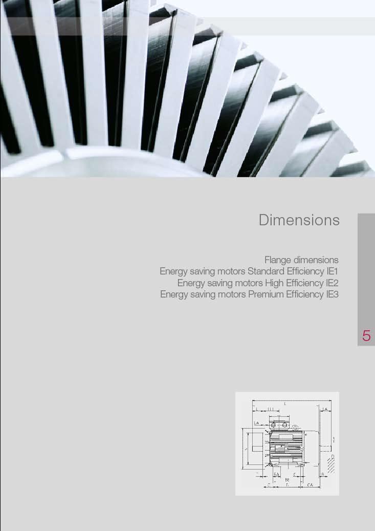
63
64 Dimensions 66
65 Notes to dimensions Dimensional designations according to EN and IEC Flange sizes in the dimensional tables are given in accordance to DIN All dimensional data in mm VEM motors GmbH reserves the right to change technical data without preceding information. Dimensional data in catalogues can lose their validity. Binding dimensional data can be requested from the VEM sales organisations. Flange dimensions Flanges with threadholes Flange type acc. to EN Flange type acc. to DIN LA M N P S T c 1 e 1 b 1 a 1 s 1 f 1 FT 65 C M5 2.5 FT 75 C M5 2.5 FT 85 C M6 2.5 FT 100 C M6 3 FT 115 C M8 3 FT 130 C M8 3.5 FT 165 C M FT 215 C M12 4 Flanges with through holes Flange type acc. to EN Flange type acc. to DIN LA M N P S T c 1 e 1 b 1 a 1 s 1 f 1 FF 100 A FF 115 A FF 130 A FF 165 A FF 215 A FF 265 A FF 300 A FF 350 A FF 400 A FF 500 A FF 600 A FF 740 A According to EN the flanges FF have through holes and the flanges FT have threadholes. The standard DIN for flanges A and C are still valid yet. Tolerances for dimension N (b 1 ) see respective dimensional tables LA (c 1 ) length of engagement 67
66 Dimensions Three-phase motors with squirrel-cage rotor Energy saving motors, Standard Efficiency IE1 Size 56 to 280 with surface ventilation, cooling method IC 411, type of protection IP 55 Type of construction IM B3 [IM 1001] Type designation Flange A AA AB AC AD B BA BB C CA D DA DB*) E EA F FA size b n f g g1 a m e w1 w2 d d1 l l1 u u1 K21O 56 K2, 4U FF M K21R 56 G2, 4 FF M K21R 63 K2, 4, 6 FF M K21R 63 G2, 4, 6 FF M K21R 71 K2, 4, 6, 8 FF M K21R 71 G2, 4, 6, 8 FF M IE1-K21R 80 K2, 4, 6, 8 FF M IE1-K21R 80 G2, 4, 6, 8 FF M IE1-K21R 90 S2, 4, 6, 8 FF M IE1-K21R 90 L2, 4, 6, 8 FF M IE1-K21R 100 L2, 4, 6, 8 FF M IE1-K21R 100 LX4, 8 FF M IE1-K21R 112 M2 FF M IE1-K21R 112 M6, 8 FF M IE1-K21R 112 MX2 FF M IE1-K21R 112 M4 FF M IE1-K21R 132 S2, 6, 8T FF M IE1-K21R 132 S4T FF M IE1-K21R 132 S2 FF M IE1-K21R 132 SX2T FF M IE1-K21R 132 SX2 FF M IE1-K21R 132 S4, 6, 8 FF M IE1-K21R 132 M4 FF M IE1-K21R 132 MX6 FF M IE1-K21R 132 M6, 8 FF M IE1-K21R 160 M2 FF M IE1-K21R 160 M4, 6, 8 FF M IE1-K21R 160 MX8 FF M IE1-K21R 160 MX2 FF M IE1-K21R 160 L2, 4, 6, 8 FF M IE1-K21R 180 M2 FF M IE1-K21R 180 M4 FF M IE1-K21R 180 L4 FF M IE1-K21R 180 L6, 8 FF M IE1-K21R 200 L2, 4, 6, 8 FF M IE1-K21R 200 LX6 FF M IE1-K21R 200 LX2 FF M IE1-K21R 225 S4, 8 FF M IE1-K21R 225 M2 FF M IE1-K21R 225 M4 FF M IE1-K21R 225 M6, 8 FF M IE1-K21R 250 M2 FF M IE1-K21R 250 M4, 6, 8 FF M IE1-K21R 280 S2 FF M IE1-K21R 280 S4, 6, 8 FF M IE1-K21R 280 M2 FF M IE1-K21R 280 M4, 6, 8 FF M *) Centre holes acc. to DIN 332-DS 68
67 Three-phase motors with squirrel-cage rotor Energy saving motors, Standard Efficiency IE1 Size 56 to 280 with surface ventilation, cooling method IC 411, type of protection IP 55 Type of construction IM B35 [IM 1001] Flange dimensions see page 67 Type designation GA GC H HA HD HD**) HH K K L LC KK Type AG LL O Hole BI t t1 h c p p A s s k k1 pattern Bl K21O 56 K2, 4U a.a KA M20 x 1.5 4L 14 K21R 56 G2, a.a KA M20 x 1.5 4L 14 K21R 63 K2, 4, a.a KA M20 x 1.5 4L 14 K21R 63 G2, 4, a.a KA M20 x 1.5 4L 14 K21R 71 K2, 4, 6, a.a KA M20 x 1.5 4L 14 K21R 71 G2, 4, 6, a.a KA M20 x 1.5 4L 14 IE1-K21R K2, 4, 6, a.a KA M20 x 1.5 4L 16 IE1-K21R 80 G2, 4, 6, a.a KA M20 x 1.5 4L 16 IE1-K21R 90 S2, 4, 6, a.a KA M25 x 1.5 4L 16 IE1-K21R 90 L2, 4, 6, a.a KA M25 x 1.5 4L 16 IE1-K21R 100 L2, 4, 6, a.a KA M25 x 1.5 4L 18 IE1-K21R 100 LX4, a.a KA M25 x 1.5 4L 20 IE1-K21R 112 M a.a KA M25 x 1.5 4L 20 IE1-K21R 112 M6, a.a KA M25 x 1.5 4L 20 IE1-K21R 112 MX a.a KA M25 x 1.5 4L 20 IE1-K21R 112 M a.a KA M25 x 1.5 4L 20 IE1-K21R 132 S2, 6, 8T a.a KA M32 x 1.5 4L 20 IE1-K21R 132 S4T a.a KA M32 x 1.5 4L 20 IE1-K21R 132 S KK 25 A M32 x 1.5 4L 35 IE1-K21R 132 SX2T a.a KA M32 x 1.5 4L 20 IE1-K21R 132 SX KK 25 A M32 x 1.5 4L 35 IE1-K21R 132 S4, 6, KK 25 A M32 x 1.5 4L 35 IE1-K21R 132 M KK 25 A M32 x 1.5 4L 35 IE1-K21R 132 MX KK 25 A M32 x 1.5 4L 35 IE1-K21R 132 M6, KK 25 A M32 x 1.5 4L 35 IE1-K21R 160 M KK 63 A M40 x 1.5 4L 35 IE1-K21R 160 M4, 6, KK 63 A M40 x 1.5 4L 35 IE1-K21R 160 MX KK 63 A M40 x 1.5 4L 35 IE1-K21R 160 MX KK 63 A M40 x 1.5 4L 35 IE1-K21R 160 L2, 4, 6, KK 63 A M40 x 1.5 4L 35 IE1-K21R 180 M KK 63 A M40 x 1.5 4L 35 IE1-K21R 180 M KK 63 A M40 x 1.5 4L 35 IE1-K21R 180 L KK 63 A M40 x 1.5 4L 35 IE1-K21R 180 L6, KK 63 A M40 x 1.5 4L 35 IE1-K21R 200 L2, 4, 6, KK 63 A M40 x 1.5 4L 35 IE1-K21R 200 LX KK 63 A M40 x 1.5 4L 35 IE1-K21R 200 LX KK 100 A M50 x 1.5 4L 35 IE1-K21R 225 S4, KK 100 A M50 x 1.5 8L 40 IE1-K21R 225 M KK 100 A M50 x 1.5 8L 40 IE1-K21R 225 M KK 100 A M50 x 1.5 8L 40 IE1-K21R 225 M6, KK 100 A M50 x 1.5 8L 40 IE1-K21R 250 M KK 200 A M63 x 1.5 8L 45 IE1-K21R 250 M4, 6, KK 200 A M63 x 1.5 8L 45 IE1-K21R 280 S KK 200 A M63 x 1.5 8L 50 IE1-K21R 280 S4, 6, KK 200 A M63 x 1.5 8L 50 IE1-K21R 280 M KK 200 A M63 x 1.5 8L 50 IE1-K21R 280 M4, 6, KK 200 A M63 x 1.5 8L 50 **) Terminal box left /right 69
68 Dimensions Three-phase motors with squirrel-cage rotor Energy saving motors, Standard Efficiency IE1 Size 315 with surface ventilation, cooling method IC 411, type of protection IP 55 Type of construction IM B3 [IM 1001] Type designation Flange A AA AB AC AD B BA BA BB C CA D DA DB*) E EA F FA size b n f g g1 a m m1 e w1 w2 d d1 l l1 u u1 IE1-K21R 315 S2 FF M IE1-K21R 315 S4, 6, 8 FF M IE1-K21R 315 M2 FF M IE1-K21R 315 M4, 6, 8 FF M IE1-K21R 315 MX2 FF M IE1-K21R 315 MX4 FF M IE1-K21R 315 MX6, 8 FF M IE1-K21R 315 MX10, 12 FF M IE1-K21R 315 MY2 FF M IE1-K21R 315 MY4, 6, 8 FF M IE1-K21R 315 L2 FF M IE1-K21R 315 L4, 6, 8 FF M IE1-K21R 315 LX2 FF M IE1-K21R 315 LX4 FF M IE1-K21R 315 LX6, 8 FF M *) Centre holes acc. to DIN 332-DS 70
69 Three-phase motors with squirrel-cage rotor Energy saving motors, Standard Efficiency IE1 Size 315 with surface ventilation, cooling method IC 411, type of protection IP 55 Type of construction IM B35 [IM 2001] Flange dimensions see page 67 Type designation GA GC H HA HD HD**) HH K K L LC KK Type AG LL AH O Bl t t1 h c p p A s s k k1 x z - r Bl IE1-K21R 315 S , KK 200 A M63 x IE1-K21R 315 S4, 6, , KK 200 A M63 x IE1-K21R 315 M , KK 200 A M63 x IE1-K21R 315 M4, 6, , KK 200 A M63 x IE1-K21R 315 MX , KK 200 A M63 x IE1-K21R 315 MX , KK 200 A M63 x IE1-K21R 315 MX6, , KK 200 A M63 x IE1-K21R 315 MX10, , KK 200 A M63 x IE1-K21R 315 MY , KK 400 B M63 x IE1-K21R 315 MY4, 6, , KK 400 B M63 x IE1-K21R 315 L , KK 400 B M63 x IE1-K21R 315 L4, 6, , KK 400 B M63 x IE1-K21R 315 LX , KK 400 B M63 x IE1-K21R 315 LX , KK 400 B M63 x IE1-K21R 315 LX6, , KK 400 B M63 x **) Terminal box right /left 71
70 Dimensions Three-phase motors with squirrel-cage rotor Energy saving motors, Standard Efficiency IE1 Size 56 to 180 with surface ventilation, cooling method IC 411, type of protection IP 55 Type of construction IM B34 [IM 2101] Flange dimensions see page 67 Type designation Flange sizes A AA AB AC AD B BA BB C CA D DA DB*) E EA F FA small big b n f g g1 a m e w1 w2 d d1 l l1 u u1 K21O 56 K2, 4U FT 65 FT M K21R 56 G2, 4 FT 65 FT M K21R 63 K2, 4, 6 FT 75 FT M K21R 63 G2, 4, 6 FT 75 FT M K21R 71 K2, 4, 6, 8 FT 85 FT , M K21R 71 G2, 4, 6, 8 FT 85 FT , M IE1-K21R 80 K2, 4, 6, 8 FT 100 FT M IE1-K21R 80 G2, 4, 6, 8 FT 100 FT M IE1-K21R 90 S2, 4, 6, 8 FT 115 FT M IE1-K21R 90 L2, 4, 6, 8 FT 115 FT M IE1-K21R 100 L2, 4, 6, 8 FT 130 FT M IE1-K21R 100 LX4, 8 FT 130 FT M IE1-K21R 112 M2 FT 130 FT M IE1-K21R 112 M6, 8 FT 130 FT M IE1-K21R 112 MX2 FT 130 FT M IE1-K21R 112 M4 FT 130 FT M IE1-K21R 132 S2, 6, 8T FT 130 FT M IE1-K21R 132 S4T FT 130 FT M IE1-K21R 132 S2 FT 130 FT M IE1-K21R 132 SX2T FT 130 FT M IE1-K21R 132 SX2 FT 130 FT M IE1-K21R 132 S4, 6, 8 FT 130 FT M IE1-K21R 132 M4 FT 165 FT M IE1-K21R 132 MX6 FT 165 FT M IE1-K21R 132 M6, 8 FT 130 FT M IE1-K21R 160 M2 FT 165 FT M IE1-K21R 160 M4, 6, 8 FT 165 FT M IE1-K21R 160 MX8 FT 165 FT M IE1-K21R 160 MX2 FT 215 FT M IE1-K21R 160 L2, 4, 6, 8 FT 215 FT M IE1-K21R 180 M4 FT M IE1-K21R 180 L6, 8 FT M *) Centre holes acc. to DIN 332-DS 72
71 Three-phase motors with squirrel-cage rotor Energy saving motors, Standard Efficiency IE1 Size 56 to 180 with surface ventilation, cooling method IC 411, type of protection IP 55 Type of construction IM B14 [IM 3601] Flange dimensions see page 67 Type designation GA GC H HA HD HD**) HH K K L LC KK Type AG LL O Hole Bl t t1 h c p p A s s k k1 x z r pattern Bl K21O 56 K2, 4U a.a KA M20 x 1.5 4L - K21R 56 G2, a.a KA M20 x 1.5 4L 14 K21R 63 K2, 4, a.a KA M20 x 1.5 4L 14 K21R 63 G2, 4, a.a KA M20 x 1.5 4L 14 K21R 71 K2, 4, 6, a.a KA M20 x 1.5 4L 14 K21R 71 G2, 4, 6, a.a KA M20 x 1.5 4L 14 IE1-K21R 80 K2, 4, 6, a.a KA M20 x 1.5 4L 16 IE1-K21R 80 G2, 4, 6, a.a KA M20 x 1.5 4L 16 IE1-K21R 90 S2, 4, 6, a.a KA M25 x 1.5 4L 16 IE1-K21R 90 L2, 4, 6, a.a KA M25 x 1.5 4L 16 IE1-K21R 100 L2, 4, 6, a.a KA M25 x 1.5 4L 18 IE1-K21R 100 LX4, a.a KA M25 x 1.5 4L 20 IE1-K21R 112 M a.a KA M25 x 1.5 4L 20 IE1-K21R 112 M6, a.a KA M25 x 1.5 4L 20 IE1-K21R 112 MX a.a KA M25 x 1.5 4L 20 IE1-K21R 112 M a.a KA M25 x 1.5 4L 20 IE1-K21R 132 S2, 6, 8T a.a KA M32 x 1.5 4L 20 IE1-K21R 132 S4T a.a KA M32 x 1.5 4L 20 IE1-K21R 132 S KK 25 A M32 x 1.5 4L 35 IE1-K21R 132 SX2T a.a KA M32 x 1.5 4L 20 IE1-K21R 132 SX KK 25 A M32 x 1.5 4L 35 IE1-K21R 132 S4, 6, KK 25 A M32 x 1.5 4L 35 IE1-K21R 132 M KK 25 A M32 x 1.5 4L 35 IE1-K21R 132 MX KK 25 A M32 x 1.5 4L 35 IE1-K21R 132 M6, KK 25 A M32 x 1.5 4L 35 IE1-K21R 160 M KK 63 A M40 x 1.5 4L 35 IE1-K21R 160 M4, 6, KK 63 A M40 x 1.5 4L 35 IE1-K21R 160 MX KK 63 A M40 x 1.5 4L 35 IE1-K21R 160 MX KK 63 A M40 x 1.5 4L 35 IE1-K21R 160 L2, 4, 6, KK 63 A M40 x 1.5 4L 35 IE1-K21R 180 M KK 63 A M40 x 1.5 4L 35 IE1-K21R 180 L6, KK 63 A M40 x 1.5 4L 35 **) Terminal box left /right 73
72 Dimensions Three-phase motors with squirrel-cage rotor Energy saving motors, Standard Efficiency IE1 Size 56 to 280 with surface ventilation, cooling method IC 411, type of protection IP 55 Type of construction IM B5 [IM 3001] Type of construction IM V1 [IM 3011] Flange dimensions see page 67 Type designation Flange AC AD D DA DB*) E EA F FA GA GC H HH L LC KK Type AG LL O Hole BI size g g1 d d1 l l1 u u1 t t1 h A k k1 pattern Bl K21O 56 K2, 4U FF M KA M20 x 1.5 4L 14 K21R 56 G2, 4 FF M KA M20 x 1.5 4L 14 K21R 63 K2, 4, 6 FF M KA M20 x 1.5 4L 14 K21R 63 G2, 4, 6 FF M KA M20 x 1.5 4L 14 K21R 71 K2, 4, 6, 8 FF M KA M20 x 1.5 4L 14 K21R 71 G2, 4, 6, 8 FF M KA M20 x 1.5 4L 14 IE1-K21R 80 K2, 4, 6, 8 FF M KA M20 x 1.5 4L 16 IE1-K21R 80 G2, 4, 6, 8 FF M KA M20 x 1.5 4L 16 IE1-K21R 90 S2, 4, 6, 8 FF M KA M25 x 1.5 4L 16 IE1-K21R 90 L2, 4, 6, 8 FF M KA M25 x 1.5 4L 16 IE1-K21R 100 L2, 4, 6, 8 FF M KA M25 x 1.5 4L 18 IE1-K21R 100 LX4, 8 FF M KA M25 x 1.5 4L 20 IE1-K21R 112 M2 FF M KA M25 x 1.5 4L 20 IE1-K21R 112 M6, 8 FF M KA M25 x 1.5 4L 20 IE1-K21R 112 MX2 FF M KA M25 x 1.5 4L 20 IE1-K21R 112 M4 FF M KA M25 x 1.5 4L 20 IE1-K21R 132 S2, 6, 8T FF M KA M32 x 1.5 4L 20 IE1-K21R 132 S4T FF M KA M32 x 1.5 4L 20 IE1-K21R 132 S2 FF M KK 25 A M32 x 1.5 4L 35 IE1-K21R 132 SX2T FF M KA M32 x 1.5 4L 20 IE1-K21R 132 SX2 FF M KK 25 A M32 x 1.5 4L 35 IE1-K21R 132 S4, 6, 8 FF M KK 25 A M32 x 1.5 4L 35 IE1-K21R 132 M4 FF M KK 25 A M32 x 1.5 4L 35 IE1-K21R 132 MX6 FF M KK 25 A M32 x 1.5 4L 35 IE1-K21R 132 M6, 8 FF M KK 25 A M32 x 1.5 4L 35 IE1-K21R 160 M2 FF M KK 63 A M40 x 1.5 4L 35 IE1-K21R 160 M4, 6, 8 FF M KK 63 A M40 x 1.5 4L 35 IE1-K21R 160 MX8 FF M KK 63 A M40 x 1.5 4L 35 IE1-K21R 160 MX2 FF M KK 63 A M40 x 1.5 4L 35 IE1-K21R 160 L2, 4, 6, 8 FF M KK 63 A M40 x 1.5 4L 35 IE1-K21R 180 M2 FF M KK 63 A M40 x 1.5 4L 35 IE1-K21R 180 M4 FF M KK 63 A M40 x 1.5 4L 35 IE1-K21R 180 L4 FF M KK 63 A M40 x 1.5 4L 35 IE1-K21R 180 L6, 8 FF M KK 63 A M40 x 1.5 4L 35 IE1-K21R 200 L2, 4, 6, 8 FF M KK 63 A M40 x 1.5 4L 35 IE1-K21R 200 LX6 FF M KK 63 A M40 x 1.5 4L 35 IE1-K21R 200 LX2 FF M KK 100 A M50 x 1.5 4L 35 IE1-K21R 225 S4, 8 FF M KK 100 A M50 x 1.5 8L 40 IE1-K21R 225 M2 FF M KK 100 A M50 x 1.5 8L 40 IE1-K21R 225 M4 FF M KK 100 A M50 x 1.5 8L 40 IE1-K21R 225 M6, 8 FF M KK 100 A M50 x 1.5 8L 40 IE1-K21R 250 M2 FF M KK 200 A M63 x 1.5 8L 45 IE1-K21R 250 M4, 6, 8 FF M KK 200 A M63 x 1.5 8L 45 IE1-K21R 280 S2 FF M KK 200 A M63 x 1.5 8L 50 IE1-K21R 280 S4, 6, 8 FF M KK 200 A M63 x 1.5 8L 50 IE1-K21R 280 M2 FF M KK 200 A M63 x 1.5 8L 50 IE1-K21R 280 M4, 6, 8 FF M KK 200 A M63 x 1.5 8L 50 *) Centre holes acc. to DIN 332-DS 74
73 Three-phase motors with squirrel-cage rotor Energy saving motors, Standard Efficiency IE1 Size 315 with surface ventilation, cooling method IC 411, type of protection IP 55 Type of construction IM B5 [IM 3001] up to size 315 MY Type of construction IM V1 [IM 3011] Flange dimensions see page 67 Type designation Flange AC AD D DA DB*) E EA F FA GA GC H HH L LC KK Type AG LL AH O Bl size g g1 d d1 l l1 u u1 t t1 h A k k1 x z - r Bl IE1-K21R 315 S2 FF M KK 200 A M63 x IE1-K21R 315 S4, 6, 8 FF M KK 200 A M63 x IE1-K21R 315 M2 FF M KK 200 A M63 x IE1-K21R 315 M4, 6, 8 FF M KK 200 A M63 x IE1-K21R 315 MX2 FF M KK 200 A M63 x IE1-K21R 315 MX4 FF M KK 200 A M63 x IE1-K21R 315 MX6, 8 FF M KK 200 A M63 x IE1-K21R 315 MX10, 12 FF M KK 200 A M63 x IE1-K21R 315 MY2 FF M KK 400 B M63 x IE1-K21R 315 MY4, 6, 8 FF M KK 400 B M63 x IE1-K21R 315 L2 FF M KK 400 B M63 x IE1-K21R 315 L4, 6, 8 FF M KK 400 B M63 x IE1-K21R 315 LX2 FF M KK 400 B M63 x IE1-K21R 315 LX4 FF M KK 400 B M63 x IE1-K21R 315 LX6, 8 FF M KK 400 B M63 x *) Centre holes acc. to DIN 332-DS 75
74 Dimensions Three-phase motors with squirrel-cage rotor Energy saving motors, Standard Efficiency IE1 Size 355 with surface ventilation, cooling method IC 411, type of protection IP 55 Type of construction IM B3 [IM 1001] Type of construction IM B35 [IM 2001] Flange dimensions see page 67 Type designation Flange A AA AB AC B BA BA BB C CA D DA DB*) E EA F FA size b n f g a m m1 e w1 w2 d d1 l l1 u u1 IE1-K22R 355 MY2, M2 FF M IE1-K22R 355 MY4, 6, 8 FF M IE1-K22R 355 M4 FF M IE1-K22R 355 M6, 8 FF M IE1-K22R 355 MX6, 8 FF M K22R 355 MX2 FF M K22R 355 LY2, L2 FF M K22R 355 MX4 FF M K22R 355 LY4, L4 FF M IE1-K22R 355 LY6, 8 FF M Type designation GA GC H HA HD HD**) HH K K L LC KK Type AG LL AH BE O Bl t t1 h c p p A s s k k1 x z - - r Bl IE1-K22R 355 MY2, M KK 630 A M72 x 2 60 IE1-K22R 355 MY4, 6, KK 630 A M72 x 2 60 IE1-K22R 355 M KK 630 A M72 x 2 60 IE1-K22R 355 M6, KK 630 A M72 x 2 60 IE1-K22R 355 MX6, KK 630 A M72 x 2 60 K22R 355 MX KK 1000 A M72 x 2 60 K22R 355 LY2, L KK 1000 A M72 x 2 60 K22R 355 MX KK 1000 A M72 x 2 60 K22R 355 LY4, L KK 1000 A M72 x 2 60 IE1-K22R 355 LY6, KK 1000 A M72 x *) Centre holes acc. to DIN 332-DS **) Terminal box tilted right /left
75 Three-phase motors with squirrel-cage rotor Energy saving motors, Standard Efficiency IE1 Size 355 with surface ventilation, cooling method IC 411, type of protection IP 55 Type of construction IM V1 [IM 3011] Flange dimensions see page 67 Type designation Flange AC AD AD**) D DA DB*) E EA F FA GA GC H HH L LC KK Type AG LL AH BE O Bl size g g1 g1 d d1 l l1 u u1 t t1 h A k k1 x z - - r Bl IE1-K22R 355 MY2, M2 FF M KK 630 A M72 x 2 60 IE1-K22R 355 MY4, 6, 8 FF M KK 630 A M72 x 2 60 IE1-K22R 355 M4 FF M KK 630 A M72 x 2 60 IE1-K22R 355 M6, 8 FF M KK 630 A M72 x 2 60 IE1-K22R 355 MX6, 8 FF M KK 630 A M72 x 2 60 K22R 355 MX2 FF M KK 1000 A M72 x 2 60 K22R 355 LY2, L2 FF M KK 1000 A M72 x 2 60 K22R 355 MX4 FF M KK 1000 A M72 x 2 60 K22R 355 LY, L4 FF M KK 1000 A M72 x 2 60 IE1-K22R 355 LY6, 8 FF M KK 1000 A M72 x 2 60 *) Centre holes acc. to DIN 332-DS **) Terminal box tilted right /left 77
76 Dimensions Three-phase motors with squirrel-cage rotor Energy saving motors, High Efficiency IE2 Size 56 to 280 with surface ventilation, cooling method IC 411, type of protection IP 55 Type of construction IM B3 [IM 1001] Type designation Flange A AA AB AC AD B BA BB C CA D DA DB*) E EA F FA size b n f g g1 a m e w1 w2 d d1 l l1 u u1 78 W21R 56 K2, 4 FF M W21R 56 G2, 4 FF M W21R 63 K2, 4 FF M W21R 63 G2, 4 FF M W21R 71 K2, 4, 6 FF M W21R 71 G2, 4, 6 FF M IE2-W21R 80 K2, 4, 6, 8 FF M IE2-WE1R 80 G2 FF M IE2-W21R 80 G4, 6, 8 FF M IE2-WE1R 90 S2, 4 FF M IE2-W21R 90 S6, 8 FF M IE2-WE1R 90 L2 FF M IE2-WE1R 90 L4 FF M IE2-W21R 90 L6, 8 FF M IE2-W21R 100 L8 FF M IE2-WE1R 100 L2 FF M IE2-WE1R 100 L4 FF M IE2-WE1R 100 LX4 FF M IE2-W21R 100 LX6, 8 FF M IE2-WE1R 112 MX2 FF M IE2-WE1R 112 MZ4 FF M IE2-W21R 112 MV2,6, 8 FF M IE2-WE1R 132 S2T FF M IE2-WE1R 132 SX2 FF M IE2-WE1R 132 S4 FF M IE2-W21R 132 S6, 8 FF M IE2-WE1R 132 M4 FF M IE2-W21R 132 M6, 8 FF M IE2-W21R 132 MX6 FF M IE2-WE1R 160 M2 FF M IE2-WE1R 160 M4 FF M IE2-W21R 160 M8 FF M IE2-W21R 160 M6, MX8 FF M IE2-WE1R 160 MX2 FF M IE2-WE1R 160 L2 FF M IE2-WE1R 160 L4 FF M IE2-W21R 160 L6, 8 FF M IE2-WE1R 180 M2 FF M IE2-WE1R 180 M4 FF M IE2-WE1R 180 L4 FF M IE2-W21R 180 L6, 8 FF M IE2-WE1R 200 L2 FF M IE2-WE1R 200 LX2 FF M IE2-WE1R 200 L4 FF M IE2-W21R 200 LX6 FF M IE2-W21R 200 L6, 8 FF M IE2-WE1R 225 M2 FF M IE2-WE1R 225 S4 FF M IE2-WE1R 225 M4 FF M IE2-W21R 225 S8 FF M IE2-W21R 225 M6 FF M IE2-W21R 225 M8 FF M IE2-WE1R 250 M2 FF M IE2-WE1R 250 M4 FF M IE2-W21R 250 M6, 8 FF M IE2-WE1R 280 S2 FF M IE2-WE1R 280 M2 FF M IE2-WE1R 280 S4 FF M IE2-WE1R 280 M4 FF M IE2-W21R 280 S6 FF M IE2-W21R 280 S8 FF M IE2-W21R 280 M6, 8 FF M *) Centre holes acc. to DIN 332-DS
77 Three-phase motors with squirrel-cage rotor Energy saving motors, High Efficiency IE2 Size 56 to 280 with surface ventilation, cooling method IC 411, type of protection IP 55 Type of construction IM B35 [IM 2001] Flange dimensions see page 67 Type designation GA GC H HA HD HD**) HH K K L LC KK Type AG LL O Hole BI t t1 h c p p A s s k k1 x z - pattern Bl W21R 56 K2, a.a KA M20 x 1.5 4L 14 W21R 56 G2, a.a KA M20 x 1.5 4L 14 W21R 63K 2, a.a KA M20 x 1.5 4L 14 W21R 63 G2, a.a KA M20 x 1.5 4L 14 W21R 71 K2, 4, a.a KA M20 x 1.5 4L 16 W21R 71 G2, 4, a.a KA M20 x 1.5 4L 16 IE2-W21R 80 K2, 4, 6, a.a KA M20 x 1.5 4L 16 IE2-WE1R 80 G a.a KA M20 x 1.5 4L 16 IE2-W21R 80 G4, 6, a.a KA M20 x 1.5 4L 16 IE2-WE1R 90 S2, a.a KA M25 x 1.5 4L 18 IE2-W21R 90 S6, a.a KA M25 x 1.5 4L 18 IE2-WE1R 90 L a.a KA M25 x 1.5 4L 18 IE2-WE1R 90 L a.a KA M25 x 1.5 4L 18 IE2-W21R 90 L6, a.a KA M25 x 1.5 4L 18 IE2-W21R 100 L a.a KA M25 x 1.5 4L 20 IE2-WE1R 100 L a.a KA M25 x 1.5 4L 20 IE2-WE1R 100 L a.a KA M25 x 1.5 4L 20 IE2-WE1R 100 LX a.a KA M25 x 1.5 4L 20 IE2-W21R 100 LX6, a.a KA M25 x 1.5 4L 20 IE2-WE1R 112 MX a.a KA M25 x 1.5 4L 20 IE2-WE1R 112 MZ a.a KA M25 x 1.5 4L 20 IE2-W21R 112 MV2,6, a.a KA M25 x 1.5 4L 20 IE2-WE1R 132 S2T a.a KK Ex M32 x 1.5 4L 20 IE2-WE1R 132 SX a.a KK 25 A M32 x 1.5 4L 35 IE2-WE1R 132 S a.a KK 25 A M32 x 1.5 4L 35 IE2-W21R 132 S6, a.a KK 25 A M32 x 1.5 4L 35 IE2-WE1R 132 M a.a KK 25 A M32 x 1.5 4L 35 IE2-W21R 132 M6, a.a KK 25 A M32 x 1.5 4L 35 IE2-W21R 132 MX a.a KK 25 A M32 x 1.5 4L 35 IE2-WE1R 160 M a.a KK 63 A M40 x 1.5 4L 35 IE2-WE1R 160 M a.a KK 63 A M40 x 1.5 4L 35 IE2-W21R 160 M a.a KK 63 A M40 x 1.5 4L 35 IE2-W21R 160 M6, MX a.a KK 63 A M40 x 1.5 4L 35 IE2-WE1R 160 MX a.a KK 63 A M40 x 1.5 4L 35 IE2-WE1R 160 L a.a KK 63 A M40 x 1.5 4L 35 IE2-WE1R 160 L a.a KK 63 A M40 x 1.5 4L 35 IE2-W21R 160 L6, a.a KK 63 A M40 x 1.5 4L 35 IE2-WE1R 180 M a.a KK 63 A M40 x 1.5 4L 35 IE2-WE1R 180 M a.a KK 63 A M40 x 1.5 4L 35 IE2-WE1R 180 L a.a KK 63 A M40 x 1.5 4L 35 IE2-W21R 180 L6, a.a KK 63 A M40 x 1.5 4L 35 IE2-WE1R 200 L a.a KK 63 A M50 x 1.5 4L 35 IE2-WE1R 200 LX a.a KK 63 A M50 x 1.5 4L 35 IE2-WE1R 200 L a.a KK 100 A M50 x 1.5 4L 35 IE2-W21R 200 LX a.a KK 100 A M50 x 1.5 4L 35 IE2-W21R 200 L6, a.a KK 63 A M50 x 1.5 4L 35 IE2-WE1R 225 M a.a KK 100 A M50 x 1.5 8L 40 IE2-WE1R 225 S a.a KK 100 A M50 x 1.5 8L 40 IE2-WE1R 225 M a.a KK 100 A M50 x 1.5 8L 45 IE2-W21R 225 S a.a KK 100 A M50 x 1.5 8L 40 IE2-W21R 225 M a.a KK 100 A M50 x 1.5 8L 45 IE2-W21R 225 M a.a KK 100 A M50 x 1.5 8L 45 IE2-WE1R 250 M a.a KK 200 A M63 x 1.5 8L 45 IE2-WE1R 250 M a.a KK 200 A M63 x 1.5 8L 50 IE2-W21R 250 M6, a.a KK 200 A M63 x 1.5 8L 50 IE2-WE1R 280 S a.a KK 200 A M63 x 1.5 8L 50 IE2-WE1R 280 M a.a KK 200 A M63 x 1.5 8L 50 IE2-WE1R 280 S a.a KK 200 A M63 x 1.5 8L 50 IE2-WE1R 280 M a.a KK 200 A M63 x 1.5 8L 50 IE2-W21R 280 S a.a KK 200 A M63 x 1.5 8L 50 IE2-W21R 280 S a.a KK 200 A M63 x 1.5 8L 50 IE2-W21R 280 M6, a.a KK 200 A M63 x 1.5 8L 55 **) Terminal box left /right Size 56/63/71/90: dimensions C, HH, L, LC are different for type of construction B35, see B5 79
78 Dimensions Three-phase motors with squirrel-cage rotor Energy saving motors, High Efficiency IE2 Size 132 to 250 with surface ventilation, cooling method IC 411, type of protection IP 55 Type of construction IM B3 [IM 1001] Type designation Flange A AA AB AC AD B BA BB C CA D DA DB*) E EA F FA size b n f g g1 a m e w1 w2 d d1 l l1 u u1 IE2-WE2R 132 S4 FF M IE2-WE2R 132 M6, 8 FF M IE2-WE2R 160 M4 FF M IE2-WE2R 160 M6, MX8 FF M IE2-WE2R 160 L4 FF M IE2-WE2R 180 L6 FF M IE2-WE2R 180 M4 FF M IE2-WE2R 200 LX2 FF M IE2-WE2R 200 LX6 FF M IE2-WE2R 225 M4 FF M IE2-WE2R 225 M6, 8 FF M IE2-WE2R 250 M4 FF M IE2-WE2R 250 M6, 8 FF M *) Centre holes acc. to DIN 332-DS 80
79 Three-phase motors with squirrel-cage rotor Energy saving motors, High Efficiency IE2 Size 132 to 250 with surface ventilation, cooling method IC 411, type of protection IP 55 Type of construction IM B35 [IM 2001] Flange dimensions see page 67 Type designation GA GC H HA HD HD**) HH K K L LC KK Type AG LL O Hole BI t t1 h c p p A s s k k1 x z - pattern Bl IE2-WE2R 132 S a.a KK 25 A M32 x 1.5 4L 35 IE2-WE2R 132 M6, a.a KK 25 A M32 x 1.5 4L 35 IE2-WE2R 160 M a.a KK 63 A M40 x 1.5 4L 35 IE2-WE2R 160 M6, MX a.a KK 63 A M40 x 1.5 4L 35 IE2-WE2R 160 L a.a KK 63 A M40 x 1.5 4L 35 IE2-WE2R 180 L a.a KK 63 A M40 x 1.5 4L 35 IE2-WE2R 180 M a.a KK 63 A M40 x 1.5 4L 35 IE2-WE2R 200 LX a.a KK 63 A M50 x 1.5 4L 35 IE2-WE2R 200 LX a.a KK 63 A M50 x 1.5 4L 35 IE2-WE2R 225 M a.a KK 100 A M50 x 1.5 8L 40 IE2-WE2R 225 M a.a KK 100 A M50 x 1.5 8L 40 IE2-WE2R 250 M a.a KK 200 A M63 x 1.5 8L 50 IE2-WE2R 250 M6, a.a KK 200 A M63 x 1.5 8L 50 **) Terminal box left /right 81
80 Dimensions Three-phase motors with squirrel-cage rotor Energy saving motors, High Efficiency IE2 Size 315 with surface ventilation, cooling method IC 411, type of protection IP 55 Type of construction IM B3 [IM 1001] Type designation Flange A AA AB AC AD B BA BA BB C CA D DA DB*) E EA F FA size b n f g g1 a m m1 e w1 w2 d d1 l l1 u u1 IE2-W21R 315 S2 FF M IE2-W21R 315 M2 FF M IE2-W21R 315 MX2 FF M IE2-W21R 315 MY2 FF M IE2-W21R 315 L2 FF M IE2-W21R 315 LX2 FF M IE2-W21R 315 S4 FF M IE2-W21R 315 M4 FF M IE2-W21R 315 MX4 FF M IE2-W21R 315 MY4 FF M IE2-W21R 315 L4 FF M IE2-W21R 315 LX4 FF M IE2-W21R 315 S6 FF M IE2-W21R 315 M6 FF M IE2-W21R 315 MX6 FF M IE2-W21R 315 MY6 FF M IE2-W21R 315 L6 FF M IE2-W21R 315 LX6 FF M IE2-W21R 315 S8 FF M IE2-W21R 315 M8 FF M IE2-W21R 315 MX8 FF M IE2-W21R 315 MY8 FF M IE2-W21R 315 L8 FF M IE2-W21R 315 LX8 FF M *) Centre holes acc. to DIN 332-DS 82
81 Three-phase motors with squirrel-cage rotor Energy saving motors, High Efficiency IE2 Size 315 with surface ventilation, cooling method IC 411, type of protection IP 55 Type of construction IM B35 [IM 2001] Flange dimensions see page 67 Type designation GA GC H HA HD HD**) HH K K L LC KK Type AG LL AH O Bl t t1 h c p p A s s k k1 x z - r Bl IE2-W21R 315 S KK 200 A M63 x IE2-W21R 315 M KK 200 A M63 x IE2-W21R 315 MX KK 200 A M63 x IE2-W21R 315 MY KK 400 B M63 x IE2-W21R 315 L KK 400 B M63 x IE2-W21R 315 LX KK 400 B M63 x IE2-W21R 315 S KK 200 A M63 x IE2-W21R 315 M KK 200 A M63 x IE2-W21R 315 MX KK 200 A M63 x IE2-W21R 315 MY KK 400 B M63 x IE2-W21R 315 L KK 400 B M63 x IE2-W21R 315 LX KK 400 B M63 x IE2-W21R 315 S KK 200 A M63 x IE2-W21R 315 M KK 200 A M63 x IE2-W21R 315 MX KK 400 B M63 x IE2-W21R 315 MY KK 400 B M63 x IE2-W21R 315 L KK 400 B M63 x IE2-W21R 315 LX KK 400 B M63 x IE2-W21R 315 S KK 200 A M63 x IE2-W21R 315 M KK 200 A M63 x IE2-W21R 315 MX KK 400 B M63 x IE2-W21R 315 MY KK 400 B M63 x IE2-W21R 315 L KK 400 B M63 x IE2-W21R 315 LX KK 400 B M63 x **) Terminal box left /right 83
82 Dimensions Three-phase motors with squirrel-cage rotor Energy saving motors, High Efficiency IE2 Size 56 to 160 with surface ventilation, cooling method IC 411, type of protection IP 55 Type of construction IM B34 [IM 2101] Flange dimensions see page 67 Type designation Flange sizes A AA AB AC AD B BA BB C CA D DA DB*) E EA F FA small big b n f g g1 a m e w1 w2 d d1 l l1 u u1 W21R 56 K2, 4 FT 65 FT M W21R 56 G2, 4 FT 65 FT M W21R 63 K2, 4 FT 75 FT M W21R 63 G2, 4 FT 75 FT M W21R 71 K2, 4, 6 FT 85 FT M W21R 71 G2, 4, 6 FT 85 FT M IE2-W21R 80 K2, 4, 6, 8 FT 100 FT M IE2-WE1R 80 G2 FT 100 FT M IE2-W21R 80 G4, 6, 8 FT 100 FT M IE2-WE1R 90 S2, 4 FT 115 FT M IE2-W21R 90 S6, 8 FT 115 FT M IE2-WE1R 90 L2 FT 115 FT M IE2-WE1R 90 L4 FT 115 FT M IE2-W21R 90 L6, 8 FT 115 FT M IE2-W21R 100 L8 FT 130 FT M IE2-WE1R 100 L2 FT 130 FT M IE2-WE1R 100 L4 FT 130 FT M IE2-WE1R 100 LX4 FT 130 FT M IE2-W21R 100 LX6, 8 FT 130 FT M IE2-WE1R 112 MX2 FT 130 FT M IE2-WE1R 112 MZ4 FT 130 FT M IE2-W21R 112 MV2, 6, 8 FT 130 FT M IE2-WE1R 132 S2T FT 130 FT M IE2-WE1R 132 SX2 FT 130 FT M IE2-WE1R 132 S4 FT 130 FT M IE2-W21R 132 S6, 8 FT 130 FT M IE2-WE1R 132 M4 FT 165 FT M IE2-W21R 132 M6, 8 FT 165 FT M IE2-W21R 132 MX6 FT 165 FT M IE2-WE1R 160 M2 FT 165 FT M IE2-WE1R 160 M4 FT 165 FT M IE2-W21R 160 M8 FT 165 FT M IE2-W21R 160 M6, MX8 FT 215 FT M IE2-WE1R 160 MX2 FT 215 FT M IE2-WE1R 160 L2 FT 215 FT M IE2-WE1R 160 L4 FT 215 FT M IE2-W21R 160 L6, 8 FT 215 FT M Optimised design series IE2-WE2R 132 S4 FT 130 FT M IE2-WE2R 132 M6, 8 FT 130 FT M IE2-WE2R 160 M4, 6, MX8 FT 165 FT M IE2-WE2R 160 L4 FT 215 FT M *) Centre holes acc. to DIN 332-DS 84
83 Three-phase motors with squirrel-cage rotor Energy saving motors, High Efficiency IE2 Size 56 to 160 with surface ventilation, cooling method IC 411, type of protection IP 55 Type of construction IM B14 [IM 3601] Flange dimensions see page 67 Type designation GA GC H HA HD HD**) HH K K L LC KK Type AG LL O Hole Bl t t1 h c p p A s s k k1 x z r pattern Bl W21R 56 K2, a.a KA M20 x 1.5 4L 14 W21R 56 G2, a.a KA M20 x 1.5 4L 14 W21R 63 K2, ,5 167 a.a KA M20 x 1.5 4L 14 W21R 63 G2, ,5 167 a.a KA M20 x 1.5 4L 14 W21R 71 K2, 4, a.a KA M20 x 1.5 4L 16 W21R 71 G2, 4, a.a KA M20 x 1.5 4L 16 IE2-W21R 80 K2, 4, 6, a.a KA M20 x 1.5 4L 16 IE2-WE1R 80 G a.a KA M20 x 1.5 4L 16 IE2-W21R 80 G4, 6, a.a KA M20 x 1.5 4L 16 IE2-WE1R 90 S2, a.a KA M25 x 1.5 4L 18 IE2-W21R 90 S6, a.a KA M25 x 1.5 4L 18 IE2-WE1R 90 L a.a KA M25 x 1.5 4L 18 IE2-WE1R 90 L a.a KA M25 x 1.5 4L 18 IE2-W21R 90 L6, a.a KA M25 x 1.5 4L 18 IE2-W21R 100 L a.a KA M25 x 1.5 4L 20 IE2-WE1R 100 L a.a KA M25 x 1.5 4L 20 IE2-WE1R 100 L a.a KA M25 x 1.5 4L 20 IE2-WE1R 100 LX a.a KA M25 x 1.5 4L 20 IE2-W21R 100 LX6, a.a KA M25 x 1.5 4L 20 IE2-WE1R 112 MX a.a KA M25 x 1.5 4L 20 IE2-WE1R 112 MZ a.a KA M25 x 1.5 4L 20 IE2-W21R 112 MV2,6, a.a KA M25 x 1.5 4L 20 IE2-WE1R 132 S2T a.a KK Ex M32 x 1.5 4L 20 IE2-WE1R 132 SX a.a KK 25 A M32 x 1.5 4L 35 IE2-WE1R 132 S a.a KK 25 A M32 x 1.5 4L 35 IE2-W21R 132 S6, a.a KK 25 A M32 x 1.5 4L 35 IE2-WE1R 132 M a.a KK 25 A M32 x 1.5 4L 35 IE2-W21R 132 M6, a.a KK 25 A M32 x 1.5 4L 35 IE2-W21R 132 MX a.a KK 25 A M32 x 1.5 4L 35 IE2-WE1R 160 M a.a KK 63 A M40 x 1.5 4L 35 IE2-WE1R 160 M a.a KK 63 A M40 x 1.5 4L 35 IE2-W21R 160 M a.a KK 63 A M40 x 1.5 4L 35 IE2-W21R 160 M6, MX a.a KK 63 A M40 x 1.5 4L 35 IE2-WE1R 160 MX a.a KK 63 A M40 x 1.5 4L 35 IE2-WE1R 160 L a.a KK 63 A M40 x 1.5 4L 35 IE2-WE1R 160 L a.a KK 63 A M40 x 1.5 4L 35 IE2-W21R 160 L6, a.a KK 63 A M40 x 1.5 4L 35 Optimised design series IE2-WE2R 132 S a.a KK 25 A M32 x 1.5 4L 35 IE2-WE2R 132 M6, a.a KK 25 A M32 x 1.5 4L 35 IE2-WE2R 160 M4, 6, MX a.a KK 63 A M40 x 1.5 4L 35 IE2-WE2R 160 L a.a KK 63 A M40 x 1.5 4L 35 **) Terminal box left /right 85
84 Dimensions Three-phase motors with squirrel-cage rotor Energy saving motors, High Efficiency IE2 Size 56 to 280 with surface ventilation, cooling method IC 411, type of protection IP 55 Type of construction IM B5 [IM 3001], Type of construction IM V1 [IM 3011] Flange dimensions see page 67 Type designation Flange AC AD D DA DB*) E EA F FA GA GC H HH L LC KK Type AG LL O Hole BI size g g1 d d1 l l1 u u1 t t1 h A k k1 x z - pattern Bl 86 W21R 56 K2, 4 FF M KA M20 x 1.5 4L 14 W21R 56 G2, 4 FF M KA M20 x 1.5 4L 14 W21R 63 K2, 4 FF M KA M20 x 1.5 4L 14 W21R 63 G2, 4 FF M KA M20 x 1.5 4L 14 W21R 71 K2, 4, 6 FF M KA M20 x 1.5 4L 16 W21R 71 G2, 4, 6 FF M KA M20 x 1.5 4L 16 IE2-W21R 80 K2, 4, 6, 8 FF M KA M20 x 1.5 4L 16 IE2-WE1R 80 G2 FF M KA M20 x 1.5 4L 16 IE2-W21R 80 G4, 6, 8 FF M KA M20 x 1.5 4L 16 IE2-WE1R 90 S2, 4 FF M KA M25 x 1.5 4L 18 IE2-W21R 90 S6, 8 FF M KA M25 x 1.5 4L 18 IE2-WE1R 90 L2 FF M KA M25 x 1.5 4L 18 IE2-WE1R 90 L4 FF M KA M25 x 1.5 4L 18 IE2-W21R 90 L6, 8 FF M KA M25 x 1.5 4L 18 IE2-W21R 100 L8 FF M KA M25 x 1.5 4L 20 IE2-WE1R 100 L2 FF M KA M25 x 1.5 4L 20 IE2-WE1R 100 L4 FF M KA M25 x 1.5 4L 20 IE2-WE1R 100 LX4 FF M KA M25 x 1.5 4L 20 IE2-W21R 100 LX6, 8 FF M KA M25 x 1.5 4L 20 IE2-WE1R 112 MX2 FF M KA M25 x 1.5 4L 20 IE2-WE1R 112 MZ4 FF M KA M25 x 1.5 4L 20 IE2-W21R 112 MV2, 6, 8 FF M KA M25 x 1.5 4L 20 IE2-WE1R 132 S2T FF M KK Ex M32 x 1.5 4L 20 IE2-WE1R 132 SX2 FF M KK 25 A M32 x 1.5 4L 35 IE2-WE1R 132 S4 FF M KK 25 A M32 x 1.5 4L 35 IE2-W21R 132 S6, 8 FF M KK 25 A M32 x 1.5 4L 35 IE2-WE1R 132 M4 FF M KK 25 A M32 x 1.5 4L 35 IE2-W21R 132 M6, 8 FF M KK 25 A M32 x 1.5 4L 35 IE2-W21R 132 MX6 FF M KK 25 A M32 x 1.5 4L 35 IE2-WE1R 160 M2 FF M KK 63 A M40 x 1.5 4L 35 IE2-WE1R 160 M4 FF M KK 63 A M40 x 1.5 4L 35 IE2-W21R 160 M8 FF M KK 63 A M40 x 1.5 4L 35 IE2-W21R 160 M6, MX8 FF M KK 63 A M40 x 1.5 4L 35 IE2-WE1R 160 MX2 FF M KK 63 A M40 x 1.5 4L 35 IE2-WE1R 160 L2 FF M KK 63 A M40 x 1.5 4L 35 IE2-WE1R 160 L4 FF M KK 63 A M40 x 1.5 4L 35 IE2-W21R 160 L6, 8 FF M KK 63 A M40 x 1.5 4L 35 IE2-WE1R 180 M2 FF M KK 63 A M40 x 1.5 4L 35 IE2-WE1R 180 M4 FF M KK 63 A M40 x 1.5 4L 35 IE2-WE1R 180 L4 FF M KK 63 A M40 x 1.5 4L 35 IE2-W21R 180 L6, 8 FF M KK 63 A M40 x 1.5 4L 35 IE2-WE1R 200 L2 FF M KK 63 A M50 x 1.5 4L 35 IE2-WE1R 200 LX2 FF M KK 63 A M50 x 1.5 4L 35 IE2-WE1R 200 L4 FF M KK 100 A M50 x 1.5 4L 35 IE2-W21R 200 LX6 FF M KK 100 A M50 x 1.5 4L 35 IE2-W21R 200 L6, 8 FF M KK 63 A M50 x 1.5 4L 35 IE2-WE1R 225 M2 FF M KK 100 A M50 x 1.5 8L 40 IE2-WE1R 225 S4 FF M KK 100 A M50 x 1.5 8L 40 IE2-WE1R 225 M4 FF M KK 100 A M50 x 1.5 8L 45 IE2-W21R 225 S8 FF M KK 100 A M50 x 1.5 8L 40 IE2-W21R 225 M6 FF M KK 100 A M50 x 1.5 8L 45 IE2-W21R 225 M8 FF M KK 100 A M50 x 1.5 8L 45 IE2-WE1R 250 M2 FF M KK 200 A M63 x 1.5 8L 45 IE2-WE1R 250 M4 FF M KK 200 A M63 x 1.5 8L 50 IE2-W21R 250 M6, 8 FF M KK 200 A M63 x 1.5 8L 50 IE2-WE1R 280 S2 FF M KK 200 A M63 x 1.5 8L 50 IE2-WE1R 280 M2 FF M KK 200 A M63 x 1.5 8L 50 IE2-WE1R 280 S4 FF M KK 200 A M63 x 1.5 8L 50 IE2-WE1R 280 M4 FF M KK 200 A M63 x 1.5 8L 50 IE2-W21R 280 S6 FF M KK 200 A M63 x 1.5 8L 50 IE2-W21R 280 S8 FF M KK 200 A M63 x 1.5 8L 50 IE2-W21R 280 M6, 8 FF M KK 200 A M63 x 1.5 8L 55 *) Centre holes acc. to DIN 332-DS
85 Three-phase motors with squirrel-cage rotor Energy saving motors, High Efficiency IE2 Size 56 to 280 with surface ventilation, cooling method IC 411, type of protection IP 55 Type of construction IM B5 [IM 3001], Type of construction IM V1 [IM 3011] Flange dimensions see page 67 Type designation Flange AC AD D DA DB*) E EA F FA GA GC H HH L LC KK Type AG LL O Hole BI size g g1 d d1 l l1 u u1 t t1 h A k k1 x z - pattern Bl IE2-WE2R 132 S4 FF M KK 25 A M32 x 1.5 4L 35 IE2-WE2R 132 M6, 8 FF M KK 25 A M32 x 1.5 4L 35 IE2-WE2R 160 M4, 6, MX8 FF M KK 63 A M40 x 1.5 4L 35 IE2-WE2R 160 L4 FF M KK 63 A M40 x 1.5 4L 35 IE2-WE2R 180 L6 FF M KK 63 A M40 x 1.5 4L 35 IE2-WE2R 180 M4 FF M KK 63 A M40 x 1.5 4L 35 IE2-WE2R 200 LX2 FF M KK 63 A M50 x 1.5 4L 35 IE2-WE2R 200 LX6 FF M KK 63 A M50 x 1.5 4L 35 IE2-WE2R 225 M4 FF M KK 100 A M50 x 1.5 8L 40 IE2-WE2R 225 M6, 8 FF M KK 100 A M50 x 1.5 8L 40 IE2-WE2R 250 M4 FF M KK 200 A M63 x 1.5 8L 50 IE2-WE2R 250 M6, 8 FF M KK 200 A M63 x 1.5 8L 50 *) Centre holes acc. to DIN 332-DS 87
86 Dimensions Three-phase motors with squirrel-cage rotor Energy saving motors, High Efficiency IE2 Size 355 with surface ventilation, cooling method IC 411, type of protection IP 55 Type of construction IM B3 [IM 1001] Type designation Flange A AA AB AC B BA BA BB C CA D DA DB*) E EA F FA size b n f g a m m1 e w1 w2 d d1 l l1 u u1 IE2-W22R 355 M2 FF M IE2-W22R 355 M4 FF M IE2-W22R 355 M6, 8 FF M IE2-W22R 355 MX6, 8 FF M W22R 355 MX2 FF M W22R 355 LY2, L2 FF M W22R 355 MX4 FF M W22R 355 LY4, L4 FF M IE2-W22R 355 LY6, 8 FF M *) Centre holes acc. to DIN 332-DS 88
87 Three-phase motors with squirrel-cage rotor Energy saving motors, High Efficiency IE2 Size 355 with surface ventilation, cooling method IC 411, type of protection IP 55 Type of construction IM B35 [IM 2001] Flange dimensions see page 67 Type designation GA GC H HA HD HD**) HH K K L LC KK Type AG LL AH BE O Bl t t1 h c p p A s s k k1 x z - - r Bl IE2-W22R 355 M KK 630 A M72 x 2 60 IE2-W22R 355 M KK 630 A M72 x 2 60 IE2-W22R 355 M6, KK 630 A M72 x 2 60 IE2-W22R 355 MX6, KK 630 A M72 x 2 60 W22R 355 MX KK 1000 A M72 x 2 60 W22R 355 LY2, L KK 1000 A M72 x 2 60 W22R 355 MX KK 1000 A M72 x 2 60 W22R 355 LY4, L KK 1000 A M72 x 2 60 IE2-W22R 355 LY6, KK 1000 A M72 x 2 60 **) Terminal box tilted right /left 89
88 Dimensions Three-phase motors with squirrel-cage rotor Energy saving motors, High Efficiency IE2 Size 315 with surface ventilation, cooling method IC 411, type of protection IP 55 Type of construction IM B5 [IM 3001] up to size 315 MY Type of construction IM V1 [IM 3011] Flange dimensions see page 67 Type designation Flange AC AD D DA DB*) E EA F FA GA GC H HH L LC KK Type AG LL AH O Bl size g g1 d d1 l l1 u u1 t t1 h A k k1 x z - r Bl IE2-W21R 315 S2 FF M KK 200 A M63 x IE2-W21R 315 M2 FF M KK 200 A M63 x IE2-W21R 315 MX2 FF M KK 200 A M63 x IE2-W21R 315 MY2 FF M KK 400 B M63 x IE2-W21R 315 L2 FF M KK 400 B M63 x IE2-W21R 315 LX2 FF M KK 400 B M63 x IE2-W21R 315 S4 FF M KK 200 A M63 x IE2-W21R 315 M4 FF M KK 200 A M63 x IE2-W21R 315 MX4 FF M KK 200 A M63 x IE2-W21R 315 MY4 FF M KK 400 B M63 x IE2-W21R 315 L4 FF M KK 400 B M63 x IE2-W21R 315 LX4 FF M KK 400 B M63 x IE2-W21R 315 S6 FF M KK 200 A M63 x IE2-W21R 315 M6 FF M KK 200 A M63 x IE2-W21R 315 MX6 FF M KK 400 B M63 x IE2-W21R 315 MY6 FF M KK 400 B M63 x IE2-W21R 315 L6 FF M KK 400 B M63 x IE2-W21R 315 LX6 FF M KK 400 B M63 x IE2-W21R 315 S8 FF M KK 200 A M63 x IE2-W21R 315 M8 FF M KK 200 A M63 x IE2-W21R 315 MX8 FF M KK 400 B M63 x IE2-W21R 315 MY8 FF M KK 400 B M63 x IE2-W21R 315 L6 FF M KK 400 B M63 x IE2-W21R 315 LX8 FF M KK 400 B M63 x *) Centre holes acc. to DIN 332-DS 90
89 Three-phase motors with squirrel-cage rotor Energy saving motors, High Efficiency IE2 Size 355 with surface ventilation, cooling method IC 411, type of protection IP 55 Type of construction IM V1 [IM 3011] Flange dimensions see page 67 Type designation Flange AC AD AD**) D DA DB*) E EA F FA GA GC H HH L LC KK Type AG LL AH BE O Bl size g g1 g1 d d1 l l1 u u1 t t1 h A k k1 x z - - r Bl IE2-W22R 355 M2 FF M KK 630 A M72 x 2 60 IE2-W22R 355 M4 FF M KK 630 A M72 x 2 60 IE2-W22R 355 M6, 8 FF M KK 630 A M72 x 2 60 IE2-W22R 355 MX6, 8 FF M KK 630 A M72 x 2 60 W22R 355 MX2 FF M KK 1000 A M72 x 2 60 W22R 355 LY2, L2 FF M KK 1000 A M72 x 2 60 W22R 355 MX4 FF M KK 1000 A M72 x 2 60 W22R 355 LY, L4 FF M KK 1000 A M72 x 2 60 IE2-W22R 355 LY6, 8 FF M KK 1000 A M72 x 2 60 *) Centre holes acc. to DIN 332-DS **) Terminal box tilted right /left 91
90 Dimensions Three-phase motors with squirrel-cage rotor Energy saving motors, Premium Efficiency IE3 Size 80 to 280 with surface ventilation, cooling method IC 411, type of protection IP 55 Type of construction IM B3 [IM 1001] Type designation Flange A AA AB AC AD B BA BB C CA D DA DB*) E EA F FA size b n f g g1 a m e w1 w2 d d1 l l1 u u1 IE3-W41R 80 K FF 165 IE3-W41R 80 G FF 165 IE3-W41R 90 S FF 165 IE3-W41R 90 L FF 165 IE3-W41R 100 L FF 215 IE3-W41R 100 LX FF 215 IE3-W41R 112 M2 FF M IE3-W41R 112 M4 FF M IE3-W41R 112 M6 FF M IE3-W41R 132 S2 FF M IE3-W41R 132 SX2 FF M IE3-W41R 132 S4 FF M IE3-W41R 132 M4 FF M IE3-W41R 132 S6 FF M IE3-W41R 132 M6 FF M IE3-W41R 132 MX6 FF M W41R 132 S8 FF M W41R 132 M8 FF M IE3-W41R 160 M2 FF M IE3-W41R 160 MX2 FF M IE3-W41R 160 L2 FF M IE3-W41R 160 M4 FF M IE3-W41R 160 L4C FF M IE3-W41R 160 M6 FF M IE3-W41R 160 L6C FF M W41R 160 M8 FF M W41R 160 MX8 FF M W41R 160 L8 FF M IE3-W41R 180 M2C FF M IE3-W41R 180 M4 FF M IE3-W41R 180 L4 FF M IE3-W41R 180 L6C FF M W41R 180 L8 FF M IE3-W41R 200 L2 FF M IE3-W41R 200 LX2C FF M IE3-W41R 200 L4C FF M IE3-W41R 200 L6 FF M IE3-W41R 200 LX6C FF M W41R 200 L8 FF M IE3-W41R 225 M2 FF M IE3-W41R 225 S4C FF M IE3-W41R 225 M4 FF M IE3-W41R 225 M6 FF M W41R 225 S8 FF M W41R 225 M8 FF M IE3-W41R 250 M2 FF M IE3-W41R 250 M4 FF M IE3-W41R 250 M6 FF M W41R 250 M8 FF M IE3-W41R 280 S2 FF M IE3-W41R 280 M2 FF M IE3-W41R 280 S4 FF M IE3-W41R 280 M4 FF M IE3-W41R 280 S6 FF M IE3-W41R 280 M6 FF M W41R 280 S8 FF M W41R 280 M8 FF M *) Centre holes acc. to DIN 332-DS 92
91 Three-phase motors with squirrel-cage rotor Energy saving motors, Premium Efficiency IE3 Size 80 to 280 with surface ventilation, cooling method IC 411, type of protection IP 55 Type of construction IM B35 [IM 2001] Flange dimensions see page 67 Type designation GA GC H HA HD HD**) HH K K L LC KK Type AG LL O Hole BI t t1 h c p p A s s k k1 x z - pattern Bl IE3-W41R 80 K KA M20 x 1 4L 16 IE3-W41R 80 G KA M20 x 1 4L 16 IE3-W41R 90 S KA M20 x 1 4L 16 IE3-W41R 90 L KA M20 x 1 4L 16 IE3-W41R 100 L KA M20 x 1 4L 18 IE3-W41R 100 LX KA M20 x 1 4L 20 IE3-W41R 112 M KK 25 A M32 x 1.5 4L 35 IE3-W41R 112 M KK 25 A M32 x 1.5 4L 35 IE3-W41R 112 M KK 25 A M32 x 1.5 4L 35 IE3-W41R 132 S KK 25 A M32 x 1.5 4L 35 IE3-W41R 132 SX KK 25 A M32 x 1.5 4L 35 IE3-W41R 132 S KK 25 A M32 x 1.5 4L 35 IE3-W41R 132 M KK 25 A M32 x 1.5 4L 35 IE3-W41R 132 S KK 25 A M32 x 1.5 4L 35 IE3-W41R 132 M KK 25 A M32 x 1.5 4L 35 IE3-W41R 132 MX KK 25 A M32 x 1.5 4L 35 W41R 132 S KK 25 A M32 x 1.5 4L 35 W41R 132 M KK 25 A M32 x 1.5 4L 35 IE3-W41R 160 M KK 63 A M40 x 1.5 4L 35 IE3-W41R 160 MX KK 63 A M40 x 1.5 4L 35 IE3-W41R 160 L KK 63 A M40 x 1.5 4L 35 IE3-W41R 160 M KK 63 A M40 x 1.5 4L 35 IE3-W41R 160 L4C KK 63 A M40 x 1.5 4L 35 IE3-W41R 160 M KK 63 A M40 x 1.5 4L 35 IE3-W41R 160 L6C KK 63 A M40 x 1.5 4L 35 W41R 160 M KK 63 A M40 x 1.5 4L 35 W41R 160 MX KK 63 A M40 x 1.5 4L 35 W41R 160 L KK 63 A M40 x 1.5 4L 35 IE3-W41R 180 M2C KK 63 A M40 x 1.5 4L 35 IE3-W41R 180 M KK 63 A M40 x 1.5 4L 35 IE3-W41R 180 L KK 63 A M40 x 1.5 4L 35 IE3-W41R 180 L6C KK 63 A M40 x 1.5 4L 35 W41R 180 L KK 63 A M40 x 1.5 4L 35 IE3-W41R 200 L KK 100 A M50 x 1.5 4L 40 IE3-W41R 200 LX2C KK 100 A M50 x 1.5 4L 40 IE3-W41R 200 L4C KK 100 A M50 x 1.5 4L 35 IE3-W41R 200 L KK 100 A M50 x 1.5 4L 35 IE3-W41R 200 LX6C KK 100 A M50 x 1.5 4L 35 W41R 200 L KK 63 A M50 x 1.5 4L 35 IE3-W41R 225 M KK 100 A M50 x 1.5 8L 45 IE3-W41R 225 S4C KK 100 A M50 x 1.5 8L 40 IE3-W41R 225 M KK 100 A M50 x 1.5 8L 45 IE3-W41R 225 M KK 100 A M50 x 1.5 8L 45 W41R 225 S KK 100 A M50 x 1.5 8L 40 W41R 225 M KK 100 A M50 x 1.5 8L 45 IE3-W41R 250 M KK 200 A M63 x 1.5 8L 55 IE3-W41R 250 M KK 200 A M63 x 1.5 8L 50 IE3-W41R 250 M KK 200 A M63 x 1.5 8L 50 W41R 250 M KK 200 A M63 x 1.5 8L 50 IE3-W41R 280 S KK 200 A M63 x 1.5 8L 55 IE3-W41R 280 M KK 200 A M63 x 1.5 8L 55 IE3-W41R 280 S KK 200 A M63 x 1.5 8L 50 IE3-W41R 280 M KK 200 A M63 x 1.5 8L 55 IE3-W41R 280 S KK 200 A M63 x 1.5 8L 55 IE3-W41R 280 M KK 200 A M63 x 1.5 8L 55 W41R 280 S KK 200 A M63 x 1.5 8L 55 W41R 280 M KK 200 A M63 x 1.5 8L 55 **) Terminal box tilted right /left 93
92 Dimensions Three-phase motors with squirrel-cage rotor Energy saving motors, Premium Efficiency IE3 Size 315 with surface ventilation, cooling method IC 411, type of protection IP 55 Type of construction IM B3 [IM 1001] Type designation Flange A AA AB AC AD B BA BA BB C CA D DA DB*) E EA F FA size b n f g g1 a m m1 e w1 w2 d d1 l l1 u u1 IE3-W41R 315 S2 A M IE3-W41R 315 M2 A M IE3-W41R 315 MX2 A M IE3-W41R 315 MY2 A M IE3-W41R 315 L2 A M IE3-W41R 315 LX2 A M IE3-W41R 315 S4 A M IE3-W41R 315 M4 A M IE3-W41R 315 MX4, MY4 A M IE3-W41R 315 L4 A M IE3-W41R 315 LX4 A M IE3-W41R 315 S6 A M IE3-W41R 315 M6 A M IE3-W41R 315 MX6 A M IE3-W41R 315 L6 A M W41R 315 S8 A M W41R 315 M8 A M W41R 315 MX8 A M W41R 315 L8 A M *) Centre holes acc. to DIN 332-DS 94
93 Three-phase motors with squirrel-cage rotor Energy saving motors, Premium Efficiency IE3 Size 315 with surface ventilation, cooling method IC 411, type of protection IP 55 Type of construction IM B35 [IM 2001] Flange dimensions see page 67 Type designation GA GC H HA HD HD**) HH K K L LC KK Type AG LL AH O Bl t t1 h c p p A s s k k1 x z - r Bl IE3-W41R 315 S KK 200 A M63 x IE3-W41R 315 M KK 200 A M63 x IE3-W41R 315 MX KK 200 A M63 x IE3-W41R 315 MY KK 400 B M63 x IE3-W41R 315 L KK 400 B M63 x IE3-W41R 315 LX KK 400 B M63 x IE3-W41R 315 S KK 200 A M63 x IE3-W41R 315 M KK 200 A M63 x IE3-W41R 315 MX4, MY KK 400 B M63 x IE3-W41R 315 L KK 400 B M63 x IE3-W41R 315 LX KK 400 B M63 x IE3-W41R 315 S KK 200 A M63 x IE3-W41R 315 M KK 400 B M63 x IE3-W41R 315 MX KK 400 B M63 x IE3-W41R 315 L KK 400 B M63 x W41R 315 S KK 200 A M63 x W41R 315 M KK 400 B M63 x W41R 315 MX KK 400 B M63 x W41R 315 L KK 400 B M63 x **) Terminal box tilted right /left 95
 E EA F FA small big b n f g g1 a m e w1 w2 d d1 l l1 u u1 IE3-W41R 80 K")


94 Dimensions Three-phase motors with squirrel-cage rotor Energy saving motors, Premium Efficiency IE3 Size 80 to 160 with surface ventilation, cooling method IC 411, type of protection IP 55 Type of construction IM B34 [IM 2101] Flange dimensions see page 67 Type designation Flange size A AA AB AC AD B BA BB C CA D DA DB*) E EA F FA small big b n f g g1 a m e w1 w2 d d1 l l1 u u1 IE3-W41R 80 K FT 100 FT 130 IE3-W41R 80 G FT 100 FT 130 IE3-W41R 90 S FT 115 FT 130 IE3-W41R 90 L FT 115 FT 130 IE3-W41R 100 L FT 130 FT 165 IE3-W41R 100 LX FT 130 FT 165 IE3-W41R 112 M2 FT 130 FT M IE3-W41R 112 M4 FT 130 FT M IE3-W41R 112 M6 FT 130 FT M IE3-W41R 132 S2 FT 130 FT M IE3-W41R 132 SX2 FT 165 FT M IE3-W41R 132 S4 FT 165 FT M IE3-W41R 132 M4 FT 165 FT M IE3-W41R 132 S6 FT 130 FT M IE3-W41R 132 M6 FT 165 FT M IE3-W41R 132 MX6 FT 165 FT M W41R 132 S8 FT 130 FT M W41R 132 M8 FT 165 FT M IE3-W41R 160 M2 FT 215 C M IE3-W41R 160 MX2 FT 215 C M IE3-W41R 160 L2 FT 215 C M IE3-W41R 160 M4 FT 215 C M IE3-W41R 160 L4C FT 215 C M IE3-W41R 160 M6 FT 215 C M IE3-W41R 160 L6C FT 215 C M W41R 160 M8 FT 215 C M W41R 160 MX8 FT 215 C M W41R 160 L8 FT 215 C M *) Centre holes acc. to DIN 332-DS 96
 HH K K L LC KK Type AG LL O Hole BI t t1 h c p p A s s k k1 x z - pattern Bl IE3-W41R 80 K 80 KA 05 92 92 M20 x 1")


95 Three-phase motors with squirrel-cage rotor Energy saving motors, Premium Efficiency IE3 Size 80 to 160 with surface ventilation, cooling method IC 411, type of protection IP 55 Type of construction IM B14 [IM 3601] Flange dimensions see page 67 Type designation GA GC H HA HD HD**) HH K K L LC KK Type AG LL O Hole BI t t1 h c p p A s s k k1 x z - pattern Bl IE3-W41R 80 K 80 KA M20 x 1 4L 16 IE3-W41R 80 G 80 KA M20 x 1 4L 16 IE3-W41R 90 S 90 KA M20 x 1 4L 16 IE3-W41R 90 L 90 KA M20 x 1 4L 16 IE3-W41R 100 L 100 KA M20 x 1 4L 18 IE3-W41R 100 LX 100 KA M20 x 1 4L 20 IE3-W41R 112 M KK 25 A M32 x 1.5 4L 35 IE3-W41R 112 M KK 25 A M32 x 1.5 4L 35 IE3-W41R 112 M KK 25 A M32 x 1.5 4L 35 IE3-W41R 132 S KK 25 A M32 x 1.5 4L 35 IE3-W41R 132 SX KK 25 A M32 x 1.5 4L 35 IE3-W41R 132 S KK 25 A M32 x 1.5 4L 35 IE3-W41R 132 M KK 25 A M32 x 1.5 4L 35 IE3-W41R 132 S KK 25 A M32 x 1.5 4L 35 IE3-W41R 132 M KK 25 A M32 x 1.5 4L 35 IE3-W41R 132 MX KK 25 A M32 x 1.5 4L 35 W41R 132 S KK 25 A M32 x 1.5 4L 35 W41R 132 M KK 25 A M32 x 1.5 4L 35 IE3-W41R 160 M KK 63 A M40 x 1.5 4L 35 IE3-W41R 160 MX KK 63 A M40 x 1.5 4L 35 IE3-W41R 160 L KK 63 A M40 x 1.5 4L 35 IE3-W41R 160 M KK 63 A M40 x 1.5 4L 35 IE3-W41R 160 L4C KK 63 A M40 x 1.5 4L 35 IE3-W41R 160 M KK 63 A M40 x 1.5 4L 35 IE3-W41R 160 L6C KK 63 A M40 x 1.5 4L 35 W41R 160 M KK 63 A M40 x 1.5 4L 35 W41R 160 MX KK 63 A M40 x 1.5 4L 35 W41R 160 L KK 63 A M40 x 1.5 4L 35 **) Terminal box tilted right /left 97
96 Dimensions Three-phase motors with squirrel-cage rotor Energy saving motors, Premium Efficiency IE3 Size 80 to 280 with surface ventilation, cooling method IC 411, type of protection IP 55 Type of construction IM B5 [IM 3001], Type of construction IM V1 [IM 3011] Flange dimensions see page 67 Type designation Flange AC AD D DA DB*) E EA F FA GA GC H HH L LC KK Type AG LL O Hole BI size g g1 d d1 l l1 u u1 t t1 h A k k1 x z - pattern Bl IE3-W41R 80 K FF 165 KA M20 x 1 4L 16 IE3-W41R 80 G FF 165 KA M20 x 1 4L 16 IE3-W41R 90 S FF 165 KA M20 x 1 4L 16 IE3-W41R 90 L FF 165 KA M20 x 1 4L 16 IE3-W41R 100 L FF 215 KA M20 x 1 4L 18 IE3-W41R 100 LX FF 215 KA M20 x 1 4L 20 IE3-W41R 112 M2 FF M KK 25 A M32 x 1.5 4L 35 IE3-W41R 112 M4 FF M KK 25 A M32 x 1.5 4L 35 IE3-W41R 112 M6 FF M KK 25 A M32 x 1.5 4L 35 IE3-W41R 132 S2 FF M KK 25 A M32 x 1.5 4L 35 IE3-W41R 132 SX2 FF M KK 25 A M32 x 1.5 4L 35 IE3-W41R 132 S4 FF M KK 25 A M32 x 1.5 4L 35 IE3-W41R 132 M4 FF M KK 25 A M32 x 1.5 4L 35 IE3-W41R 132 S6 FF M KK 25 A M32 x 1.5 4L 35 IE3-W41R 132 M6 FF M KK 25 A M32 x 1.5 4L 35 IE3-W41R 132 MX6 FF M KK 25 A M32 x 1.5 4L 35 W41R 132 S8 FF M KK 25 A M32 x 1.5 4L 35 W41R 132 M8 FF M KK 25 A M32 x 1.5 4L 35 IE3-W41R 160 M2 FF M KK 63 A M40 x 1.5 4L 35 IE3-W41R 160 MX2 FF M KK 63 A M40 x 1.5 4L 35 IE3-W41R 160 L2 FF M KK 63 A M40 x 1.5 4L 35 IE3-W41R 160 M4 FF M KK 63 A M40 x 1.5 4L 35 IE3-W41R 160 L4C FF M KK 63 A M40 x 1.5 4L 35 IE3-W41R 160 M6 FF M KK 63 A M40 x 1.5 4L 35 IE3-W41R 160 L6C FF M KK 63 A M40 x 1.5 4L 35 W41R 160 M8 FF M KK 63 A M40 x 1.5 4L 35 W41R 160 MX8 FF M KK 63 A M40 x 1.5 4L 35 W41R 160 L8 FF M KK 63 A M40 x 1.5 4L 35 IE3-W41R 180 M2C FF M KK 63 A M40 x 1.5 4L 35 IE3-W41R 180 M4 FF M KK 63 A M40 x 1.5 4L 35 IE3-W41R 180 L4 FF M KK 63 A M40 x 1.5 4L 35 IE3-W41R 180 L6C FF M KK 63 A M40 x 1.5 4L 35 W41R 180 L8 FF M KK 63 A M40 x 1.5 4L 35 IE3-W41R 200 L2 FF M KK 100 A M50 x 1.5 4L 40 IE3-W41R 200 LX2C FF M KK 100 A M50 x 1.5 4L 40 IE3-W41R 200 L4C FF M KK 100 A M50 x 1.5 4L 35 IE3-W41R 200 L6 FF M KK 100 A M50 x 1.5 4L 35 IE3-W41R 200 LX6C FF M KK 100 A M50 x 1.5 4L 35 W41R 200 L8 FF M KK 63 A M50 x 1.5 4L 35 IE3-W41R 225 M2 FF M KK 100 A M50 x 1.5 8L 45 IE3-W41R 225 S4C FF M KK 100 A M50 x 1.5 8L 40 IE3-W41R 225 M4 FF M KK 100 A M50 x 1.5 8L 45 IE3-W41R 225 M6 FF M KK 100 A M50 x 1.5 8L 45 W41R 225 S8 FF M KK 100 A M50 x 1.5 8L 40 W41R 225 M8 FF M KK 100 A M50 x 1.5 8L 45 IE3-W41R 250 M2 FF M KK 200 A M63 x 1.5 8L 55 IE3-W41R 250 M4 FF M KK 200 A M63 x 1.5 8L 50 IE3-W41R 250 M6 FF M KK 200 A M63 x 1.5 8L 50 W41R 250 M8 FF M KK 200 A M63 x 1.5 8L 50 IE3-W41R 280 S2 FF M KK 200 A M63 x 1.5 8L 55 IE3-W41R 280 M2 FF M KK 200 A M63 x 1.5 8L 55 IE3-W41R 280 S4 FF M KK 200 A M63 x 1.5 8L 50 IE3-W41R 280 M4 FF M KK 200 A M63 x 1.5 8L 55 IE3-W41R 280 S6 FF M KK 200 A M63 x 1.5 8L 55 IE3-W41R 280 M6 FF M KK 200 A M63 x 1.5 8L 55 W41R 280 S8 FF M KK 200 A M63 x 1.5 8L 55 W41R 280 M8 FF M KK 200 A M63 x 1.5 8L 55 *) Centre holes acc. to DIN 332-DS 98
97 Three-phase motors with squirrel-cage rotor Energy saving motors, Premium Efficiency IE3 Size 315 with surface ventilation, cooling method IC 411, type of protection IP 55 Type of construction IM B5 [IM 3001] up to size 315 MY Type of construction IM V1 [IM 3011] Flange dimensions see page 67 Type designation Flange AC AD**) D DA DB*) E EA F FA GA GC H HH L LC KK Type AG LL AH O Bl size g g1 d d1 l l1 u u1 t t1 h A k k1 x z - r Bl IE3-W41R 315 S2 FF M KK 200 A M63 x IE3-W41R 315 M2 FF M KK 200 A M63 x IE3-W41R 315 MX2 FF M KK 200 A M63 x IE3-W41R 315 MY2 FF M KK 400 B M63 x IE3-W41R 315 L2 FF M KK 400 B M63 x IE3-W41R 315 LX2 FF M KK 400 B M63 x IE3-W41R 315 S4 FF M KK 200 A M63 x IE3-W41R 315 M4 FF M KK 200 A M63 x IE3-W41R 315 MX4, MY4 FF M KK 400 B M63 x IE3-W41R 315 L4 FF M KK 400 B M63 x IE3-W41R 315 LX4 FF M KK 400 B M63 x IE3-W41R 315 S6 FF M KK 200 A M63 x IE3-W41R 315 M6 FF M KK 400 B M63 x IE3-W41R 315 MX6 FF M KK 400 B M63 x IE3-W41R 315 L6 FF M KK 400 B M63 x W41R 315 S8 FF M KK 200 A M63 x W41R 315 M8 FF M KK 400 B M63 x W41R 315 MX8 FF M KK 400 B M63 x W41R 315 L8 FF M KK 400 B M63 x *) Centre holes acc. to DIN 332-DS **) Terminal box tilted right/left 99
98 Dimensions Three-phase motors with squirrel-cage rotor Energy saving motors, Premium Efficiency IE3 Size 315 with surface ventilation, cooling method IC 411, type of protection IP 55 Type of construction IM B3 [IM 1001] Type of construction IM B35 [IM 2001] Flange dimensions see page 67 Type designation Flange A AA AB AC B BA BA BB C CA D DA DB*) E EA F FA size b n f g a m m1 e w1 w2 d d1 l l1 u u1 IE3-W41R 355 M2 FF M IE3-W41R 355 M 4 FF M IE3-W41R 355 M6 FF M IE3-W41R 355 MX6 FF M IE3-W41R 355 L 6 FF M IE3-W41R 355 LX6 FF M W41R 355 MY8 FF M W41R 355 M8 FF M W41R 355 MX8 FF M W41R 355 LY8 FF M Type designation GA GC H HA HD HD**) HH K K L LC KK Type AG LL AH BE O Bl t t1 h c p p A s s k k1 x z - - r Bl IE3-W41R 355 M KK 630 A M72 x 2 60 IE3-W41R 355 M KK 630 A M72 x 2 60 IE3-W41R 355 M KK 630 A M72 x 2 60 IE3-W41R 355 MX KK 630 A M72 x 2 60 IE3-W41R 355 L KK 1000 A M72 x 2 60 IE3-W41R 355 LX KK 1000 A M72 x 2 60 W41R 355 MY KK 630 A M72 x 2 60 W41R 355 M KK 630 A M72 x 2 60 W41R 355 MX KK 630 A M72 x 2 60 W41R 355 LY KK 1000 A M72 x *) Centre holes acc. to DIN 332-DS **) Terminal box tilted right /left
 D DA DB*) E EA F FA GA GC H HH L LC KK Type AG LL AH O Bl size g g1 d d1 l l1 u u1 t t1 h A k k1 x z - r Bl IE3-W41R 355 M2 FF")
99 Three-phase motors with squirrel-cage rotor Energy saving motors, Premium Efficiency IE3 Size 315 with surface ventilation, cooling method IC 411, type of protection IP 55 Type of construction IM V1 [IM 3011] Flange dimensions see page 67 Type designation Flange AC AD**) D DA DB*) E EA F FA GA GC H HH L LC KK Type AG LL AH O Bl size g g1 d d1 l l1 u u1 t t1 h A k k1 x z - r Bl IE3-W41R 355 M2 FF M KK 630 A M72 x 2 60 IE3-W41R 355 M 4 FF M KK 630 A M72 x 2 60 IE3-W41R 355 M6 FF M KK 630 A M72 x 2 60 IE3-W41R 355 MX6 FF M KK 630 A M72 x 2 60 IE3-W41R 355 L 6 FF M KK 1000 A M72 x 2 60 IE3-W41R 355 LX6 FF M KK 1000 A M72 x 2 60 W41R 355 MY8 FF M KK 630 A M72 x 2 60 W41R 355 M8 FF M KK 630 A M72 x 2 60 W41R 355 MX8 FF M KK 630 A M72 x 2 60 W41R 355 LY8 FF M KK 1000 A M72 x 2 60 *) Centre holes acc. to DIN 332-DS **) Terminal box tilted right /left 101
Three-phase asynchronous motors for low voltage with squirrel-cage rotor. with EU efficiency classification
 Three-phase asynchronous motors for low voltage with squirrel-cage rotor with EU efficiency classification Contents Page Introduction 3 Standards and regulations 4 Efficiency 5 Bearings / Bearing lubrication
Asynchronous generators
 Asynchronous generators Contents Product description 13/2 Overview of technical data 13/3 Motor selection data Series G4.R on the basis of Premium Efficiency IE3 13/4 Series GE.R on the basis of High Efficiency
COMMISSION REGULATION (EC)
") L 191/26 Official Journal of the European Union 23.7.2009 COMMISSION REGULATION (EC) No 640/2009 of 22 July 2009 implementing Directive 2005/32/EC of the European Parliament and of the Council with regard
L 191/26 Official Journal of the European Union 23.7.2009 COMMISSION REGULATION (EC) No 640/2009 of 22 July 2009 implementing Directive 2005/32/EC of the European Parliament and of the Council with regard
Standardmotoren Standard motors
 Standardmotoren Standard motors Contents Product description 2/2 Overview of technical data 2/5 2 Series W4.R for Premium Efficiency IE3 2/6 Series WE.R for High Efficiency IE2 2/14 Series K2.R for Standard
Three-phase roller table motors with squirrel-cage rotor for the application at the frequency converters Series A21O, A20O, ARB, ARC.
 Three-phase roller table motors with squirrel-cage rotor for the application at the frequency converters Series A21O, A20O, ARB, ARC Product summary VEM motors GmbH Introduction Roller table motors are
Three-phase motors for marine use
 Three-phase motors for marine use Contents Product description 11/2 Overview of technical data 11/7 Series K.../W4.. for Premium Efficiency IE3 11/8 Series K.../WE.. for High Efficiency IE2 11/12 Series
Low voltage asynchronous motors Motors for use in potentially explosive atmospheres
 Low voltage asynchronous motors Motors for use in potentially explosive atmospheres Type of protection Non sparking n Type of protection Flame-proof enclosure d/de Type of protection Protected by enclosure
Three-phase asynchronous motors
 Three-phase asynchronous motors for low voltage with squirrel-cage rotor Product specification Series K11R, K21R and K22R Introduction Standards and regulations Progressive correspondence between output
New Generation 1LE1/1PC1
 New Generation LE/PC /2 Orientation /2 Overview /3 Benefits /4 Application /4 Technical specifications /5 Selection and ordering data /7 More information /8 General Line motors with shorter delivery time
From 16 June 2011, motors placed for the first-time on the market shall have a minimum efficiency class of IE2.
 INTRODUCTION New efficiency classes for the low-voltage three-phase motors (IE = International Efficiency). Along with the international discussion on energy efficiency a worldwide harmonized energy efficiency
الهيئة السعىدية للمىاصفبت والمقبييس والجىدة Saudi Standards, Metrology and Quality Org (SASO)
") الهيئة السعىدية للمىاصفبت والمقبييس والجىدة Saudi Standards, Metrology and Quality Org (SASO) Draft Standard SASO IEC 60034-30-1:XXXX ROTATING ELECTRICAL MACHINES Part 30-1: Efficiency classes of line
الهيئة السعىدية للمىاصفبت والمقبييس والجىدة Saudi Standards, Metrology and Quality Org (SASO) Draft Standard SASO IEC 60034-30-1:XXXX ROTATING ELECTRICAL MACHINES Part 30-1: Efficiency classes of line
Built-in motors. Contents. Product description 7/2 Overview of technical data 7/3
 Built-in motors Contents Product description 7/2 Overview of technical data 7/3 Motor selection data Series W4.R (corresponds to Efficiency IE3) 7/4 Series WE.R (corresponds to High Efficiency IE2) 7/6
Technical Documentation
 Technical Documentation LOW VOLTAGE THREE PHASE TEFC CAGE MOTORS IE316EN Mission, Vision, Targets Our electric motors and generators are optimized in accordance with our client's technical and economical
How do you take the first step towards an energy efficient future?
 How do you take the first step towards an energy efficient future? Low-voltage induction motors according to the new standard and new classes Answers for industry. EU Directive 2005/32/EC and IEC 60034-30
Three-phase asynchronous motors with squirrel-cage rotor for potentially explosive atmospheres
 Three-phase asynchronous motors with squirrel-cage rotor for potentially explosive atmospheres VEM motors GmbH Table of contents Page Technical explications Motors in the increased safety type of protection
Asynchronous, Low Voltage, Squirrel Cage, Three Phase Electric Motors
 Asynchronous, Low Voltage, Squirrel Cage, Three Phase Electric Motors Series R2, Frame 63 355 Introduction KHM R2 series cast iron motors are totally enclosed fan cooled, 3 phase, and squirrel cage induction
Technical Documentation
 Technical Documentation LOW VOLTAGE THREE PHASE TEFC CAGE MOTORS IE315EN Mission, Vision, Targets Our electric motors and generators are optimized in accordance with our client's technical and economical
Efficiency classes of single-speed three-phase, cage-induction motors
 Efficiency classes of single-speed three-phase, cage-induction motors New rules in the EU and Worldwide 30-40% of the generated electrical energy worldwide is consumed by electric motors Savings potential
ELECTRIC MOTORS. Selection. Starting torque and nominal torque
 SELECTION PROCEDURE The output powers published overleaf are based upon continuous maximum rating conditions. Therefore design factors for above average running periods do not normally affect the selection.these
Low voltage electrical machines
 Low voltage electrical machines IEC motors with squirrel-cage rotor for mains and converter-fed operation IEC motors with slip-ring rotor Branch-specific versions Asynchronous generators Permanent-magnet
Permanent-magnet synchronous motors
 Permanent-magnet synchronous motors Contents Product description 12/2 Overview of technical data 12/4 Motor selection data Series PE.. for Super Premium Efficiency IE4 1) 12/5 Series P, high-power motors
EU MEPS for low voltage electric motors
 EU MEPS for low voltage electric motors EU MEPS in brief EU MEPS (European Minimum Energy Performance Standard) sets mandatory minimum efficiency levels for electric motors introduced into the European
SINGLE PHASE TEFC CAGE MOTORS
 SINGLE PHASE TEFC CAGE MOTORS 2 SINGLE PHASE TEF CAGE MOTORS Mechanical protection: IP 54 Voltage: 220 V, 50 Hz Type Output power P N kw Rated speed n N min -1 Efficiency % Power factor cos Rated current
LARGE THREE-PHASE SQUIRREL CAGE ASYNCHRONOUS MOTORS FOR HEAVY DUTY APPLICATIONS ADH SERIES
 LARGE THREE-PHASE SQUIRREL CAGE ASYNCHRONOUS MOTORS FOR HEAVY DUTY APPLICATIONS ADH SERIES FRAMES 355 560 355kW 1500kW (1500rpm) FOR INVERTER DUTY Code Declaration of conformity The motors described in
New efficiency standards and directives applicable to motors in Europe
 New efficiency standards and directives applicable Foreword Regulation 640/2009 of the directive, known as ErP, has been place in force since 2011, June 16 th. Some non-eu countries, such as Switzerland
CONTENTS 1 GENERAL 2 STANDARDS. 3 TECHNICAL FEATURES 3.1 Basic Technical Data 3.2 Standard Accessories 3.3 Tolerances
 CONTENTS 1 GENERAL 2 STANDARDS 3 TECHNICAL FEATURES 3.1 Basic Technical Data 3.2 Standard Accessories 3.3 Tolerances 4 MOTOR DESIGN 4.1 Stator Casing 4.2 Stator Core with Winding 4.3 Stator Winding 4.4
FLSD (E) Atmospheres containing explosive GAS totally enclosed three-phase asynchronous motors General information
 Atmospheres containing explosive GAS totally enclosed three-phase asynchronous motors General information") (E) Atmospheres containing explosive GAS General information Flameproof totally enclosed three-phase asynchronous motors, FLSD (E) series, according to IEC 60034, 60038, 60072, 60079-0 and 60079-1, EN
(E) Atmospheres containing explosive GAS General information Flameproof totally enclosed three-phase asynchronous motors, FLSD (E) series, according to IEC 60034, 60038, 60072, 60079-0 and 60079-1, EN
COMBROIND001_= THREE PHASE SQUIRREL CAGE INDUCTION MOTORS. IE1 motors MAA - BAA Series IE2 motors MAQ - BAQ Series
 COMBROIND001_= THREE PHASE SQUIRREL CAGE INDUCTION MOTORS IE1 motors MAA - BAA Series IE2 motors MAQ - BAQ Series 03 07 07 08 12 15 15 16 18 20 SPECIFICATIONS AND STANDARDS IE1 - MAA / BAA Series Technical
EU Regulation for Premium Efficiency IE3 motors 2, 4, 6 poles efficienza
 EU Regulation for Premium Efficiency IE3 motors 2, 4, 6 poles efficienza Regulations (EC) 640/2009 and 04/2014 establish the conditions for the conversion to the new energy-efficient technology as requested
CONTENTS 1 GENERAL 2 STANDARDS. 3 TECHNICAL FEATURES 3.1 Basic Design Data 3.2 Standard Accessories 3.3 Tolerances
 CONTENTS 1 GENERAL 2 STANDARDS 3 TECHNICAL FEATURES 3.1 Basic Design Data 3.2 Standard Accessories 3.3 Tolerances 4 MOTOR DESIGN 4.1 Stator Casing 4.2 Stator Core with Winding 4.3 Stator Winding and Insulation
Motors for use on a frequency converter
 Motors for use on a frequency converter Contents Motors for use on a frequency converter Contents Introduction 4 Motors with standard insulation 4 Motors with reinforced winding insulation 4 Motors for
General Specifications. Cooling Method 3M series are IC 411 Standard. IC 416, IC 418 can be provided Upon request
 3M SERIES Three Phases Low Voltage Asynchronous Motors 3M Series Vilma motors are designed and manufactured with high quality materials and workmanship in order to meet demanding and arduous operation
Table of contents. Three-phase asynchronous motors DA
 be in motion be in motion AC Asynchronous Motors DA 100-280 Table of contents 1. Three-phase asynchronous motor DA 100-280... 3 1.1. General technical data... 3 1.2. Ratings definition for ventilated
SWE SERIES (IE3) WONDER ELECTRIC MOTOR (S) PTE LTD. Energy Saving Low Noise Environmental Friendly IEC Dimension Low Vibration European Design
 WONDER ELECTRIC MOTOR (S) PTE LTD. Energy Saving Low Noise Environmental Friendly IEC Dimension Low Vibration European Design") RANGE OF PRODUCTS Three phase asynchronous squirrel-cage & slip ring induction motors Three phase asynchronous self-braking motors Hollow shaft rotor motors Cooling tower motors High motors, (IE2) (IE3)
RANGE OF PRODUCTS Three phase asynchronous squirrel-cage & slip ring induction motors Three phase asynchronous self-braking motors Hollow shaft rotor motors Cooling tower motors High motors, (IE2) (IE3)
Five years ahead of the future...
 ELEKTROMOTOREN \ Permanent-Magnet-Motoren Five years ahead of the future... Energy-saving Motors Achieve a New Efficiency Class Fig.1. Stephan Hensel The rise in energy costs in recent years has made the
1LG0 Low-voltage Motors
 Low-voltage motors up to 315kW Catalog D81.5.1 1LG Low-voltage Motors Answers for industry. 1 Table of Contents Overview 3 Motor standards 5 Mechanical design 6 Electrical design 1 Converter fed application
VEM motors Thurm GmbH
 VEM motors Thurm GmbH Installation, Operating and Maintenance Instructions Single-Phase Squirrel-Cage Induction Motors, Standard Version March 2005 1. General To avoid damage to the motors and equipment
THREE-PHASE ASYNCHRONOUS MOTORS EFFICIENCY CLASS ACCORDING IEC
 THREE-PHASE ASYNCHRONOUS MOTORS EFFICIENCY CLASS ACCORDING IEC 60034-30 1st EDITION IE1/IE2-MS IE1/IE2-EG Series IE1 Standard efficiency IE2 High efficiency THREE-PHASE ASYNCHRONOUS MOTORS EFFICIENCY CLASS
champion series motors
 Introducing A brand new series of Super Performers Data Sheet champion series motors FRAME SIZE 63-132M TEFC 3 Phase Squirrel Cage Induction Motors Siemens CHAMPION Series Cage Motors are suitable for
Rexroth IndraDyn E. Standard Motors MOT-FC for Frequency Converter Operation. Project planning manual R Edition 03
 Rexroth IndraDyn E Standard Motors MOT-FC for Frequency Converter Operation Project planning manual R911343624 Edition 03 Bosch Rexroth AG DOK-MOTOR*-MOT-FC*****-PR03-EN-P Title Type of Documentation Document
1. SPECIFICATION. Altitude of motor installation. Information: Resistance and temperature specifications of the PTC thermistor / posistor/.
 1. SPECIFICATION 5 GENERAL INFORMATION Motors with parameters according to the data sheet comply with the requirements of the IEC 60034-1 standard, and IEC 60034-30 class efficiency IE2 Motor versions:
Table of contents. Three-phase asynchronous motors DA
 Table of contents 1. Three-phase asynchronous motor DA 100-280... 5 1.1. General technical data... 5 1.2. General safety instructions... 6 1.3. Definitions of power ratings... 7 1.3.1. Definitions of power
Motors for converterfed operation
 Motors for converterfed operation Contents Product description 4/2 Overview of technical data 4/7 Motor selection data Standard insulation (up to 420 V): Series IE3-W4.R, IE2-WE.R, K2.R 4/8 KU insulation
High voltage flameproof induction motors The simplest solution for hazardous environments
 High voltage flameproof induction motors The simplest solution for hazardous environments We offer motors and generators, services and expertise that save energy and improve our customers processes over
CE Marking. Number of poles. Core Length. Frame size
 269 Electric Motors General Information CHALLENGE series three phase asynchronous AC electric motors, Are totally enclosed fan cooled (IC-411) squirrel caged type, With IP55 enclosure protection, Class
Low voltage asynchronous motors IEC motors with squirrel-cage rotor
 Low voltage asynchronous motors IEC motors with squirrel-cage rotor Standard motors Energy saving motors CEMEP Energy saving motors EPAct Non-ventilated motors Forced-ventilated motors Built-in motors
Customised drive solutions
 Customised drive solutions Electric motors & systems Drive components Services Introduction 03 Halm quality drive technology Over 50 years of experience in developing electric motors with asynchronous
Explosion and flame-proof cast iron electric motors
 Explosion and flame-proof cast iron electric motors EEx-d, EEx-de, IIB, IIC II, 2G IP55 II, 2G&D IP66 T4, T5, T6 Frame size 56 to 160 3 phases Voltage 230/400 V 50Hz Voltage 265/460V 60Hz Types of mounting
HIGH EFFICIENCY INDUCTION MOTORS COMBROHEF001_=
 COMBROHEF001_= HIGH EFFICIENCY INDUCTION MOTORS High efficiency induction motors General specifications Rated outputs and efficiency values are in accordance with IEC 60034-30-1 all parameters are measured
IEC : CONTENTS
 IEC 60034-30:2008 1 CONTENTS FOREWORD... 2 INTRODUCTION... 4 1 Scope... 6 2 Normative references... 6 3 Terms, definitions and symbols... 6 3.1 Terms and definitions... 6 3.2 Symbols... 7 4 Fields of application
This catalogue also includes cooling medium pumps of the types DKP and EKP.
 AUTRIA INTRODUCTION FFD offers a full range of low voltage electric motors, single phase motors as well as three phase squirrel cage induction motors for continuous duty. All motors are manufactured according
Modular DR motor concept: Standard AC motors and energy-efficient motors of efficiency class IE
 Modular DR motor concept: Standard AC motors and energy-efficient motors of efficiency class IE Features DR motors comply with all international standards and meet the new parts of the motor standard IEC
COMPARISON OF ENERGY EFFICIENCY DETERMINATION METHODS FOR THE INDUCTION MOTORS
 COMPARISON OF ENERGY EFFICIENCY DETERMINATION METHODS FOR THE INDUCTION MOTORS Bator Tsybikov 1, Evgeniy Beyerleyn 1, *, and Polina Tyuteva 1 1 Tomsk Polytechnic University, 634050, Tomsk, Russia Abstract.
CORE VALUES TECHNOLOGIES ESS-ESD PRODUCT CATALOGUE Enjoy the peace of mind ENGINE POWER SUPPLIERS AND EQUIPMENT HEAT
 TECHNOLOGIES ENGINE POWER SUPPLIERS AND EQUIPMENT HEAT Enjoy the peace of mind ESS-ESD PRODUCT CATALOGUE CORE VALUES PEACE OF MIND EFFICIENCY FAIRNESS RESPONSIBILITY CUSTOMER ORIENTATION GROWING DEVELOPED
: B3; B5; B14; B34; B35; V1
 ATT WE series (Eff1) are 3-phase TEFC Cast-Iron high efficiency general purpose induction motors, which are designed to meet or exceed the requirements for energy efficiency such as: European Eff1, Australia
Explosion and flame-proof single phase electric motors
 Explosion and flame-proof single phase electric motors EEx-d, EEx-de, IIB, IIC II, 2G IP55 II, 2G&D IP66 T4, T5, T6 Frame size 56 to 112 Single phase Voltage 230 50Hz Voltage 265 60Hz Types of mounting
MVSI-TS. Split covers. Technical features
 MVSI-TS Split covers The MVSI-TS series, obtained directly from the MVSI series, is characterized by the split weight covers. The weight cover is divided into two halves that can be removed in a radial
MVSI. Technical features
 MVSI The MVSI series represents the line of reference products for manufacturer s of vibrating machines and plants operating in many industrial sectors and is made up of the largest range on the market,
Mounting & Maintenance Instructions OMT1 & OMT2 Motors
 Mounting & Maintenance Instructions OMT1 & OMT2 Motors Seite 1 von 10 Inhalt Seite 1 General information 3 2 Delivery 3 3 Mounting 3 4 Coupling 3 4.1 Direct coupling 3 4.2 Indirect coupling 4 4.2.1 Flat
GMP-Type. Key Features: Integrated Motor-Pump Units
 Integrated Motor-Pump Units GMP-Type Key Features: Direct coupling between motor and pump Rotation: Right (viewed from shaft end) Electric motor mounting type: special B3-B14 (IEC 34-7) Rated Voltage:
SERVO MOTORS BRUSHLESS SERVO MOTORS OPERATING INSTRUCTIONS 2016
 SERVO MOTORS BRUSHLESS SERVO MOTORS OPERATING INSTRUCTIONS 2016 3009/16 en Ed.02.2016 Read these Operating Instructions before performing any transportation, installation, commissioning, maintenance or
Series E4F E5F
 Three Phase Induction Motors With Rotors Wound for Hoists Series E4F 160-315 E5F 355-400 ASI NT 003.1 I N D E X Use 2 Electrical Tolerances 9 Mechanical Tolerances 9 General Characteristics 2 Technical
Press information. Using energy-efficient electric Motors. Meeting the International Energy Directives. October 2013
 Press information Press contact Geoff Spear Address Fraser Rd, Priory Business Park Bedford, MK44 3WH Telephone 01234 753227 E-mail Geoff.spear@lenze.com Website www.lenze.com Using energy-efficient electric
Lenze. Drives with worm gearboxes 52.
 6 887 Lenze Drives with worm gearboxes 5. Lenze Drive Systems GmbH, Postfach 0 5, D-76 Hameln, Site: Groß Berkel, Hans-Lenze-Straße, D-855 Aerzen, Phone ++9 (0) 55 8-0, Telefax ++9 (0) 55 8- E-Mail: Lenze@Lenze.de
High efficiency induction motors
 High efficiency induction motors Technical data Type Power Speed Efficiency Power factor Current Rated current Breakdown Sound pressure level Moment of Inertia η cosφ I n T n I s /I n T s T max L pa J
Ordering information. When placing an order, specify motor type, size and product code according to the following example.
 Ordering information When placing an order, specify motor type, size and product code according to the following example. Example Motor type M3AA 112 MB Pole number 4 Mounting arrangement (IM-code) IM
TYPE 2 poles 4 poles 6 poles 8 poles 2 / 4 poles 4 / 8 poles 2 / 8 poles 4 / 16 poles
 BAH-BAHS series Overwiew MGM Electric Motors was established in 1950 as a brake motors manufacturer. MGM is today a world leading manufacturer of this line of products. MGM brake motors are designed and
EPACT ENERGY POLICY ACT OF 1992: THE SCOPE OF ELECTRIC MOTORS SUBJECT TO EFFICIENCY STANDARDS ON OCTOBER
 EPACT ENERGY POLICY OF 1992: THE SCOPE OF ELECTRIC MOTORS SUBJECT TO EFFICIENCY STANDARDS ON OCTOBER 24, 1997 The Energy Policy Act of 1992 (EPAct) covering efficiency levels of general purpose industrial
Design specifications
 Design specifications Design To relevant standards: IEC, VDE, DIN, ISO, EN With squirrel-cage or slipring rotor Degree of protection IP 55 / IP 65 Cooling method IC511, suitable for both indoor and outdoor
Contents. Introduction 5. Technical explanations 7. Basic version 67. Energy saving motors as specified in CEMEP 135
 Contents Introduction 5 Technical explanations 7 Basic version 67 Energy saving motors as specified in CEMEP 135 Energy saving motors as specified in EPAct 139 Motors for use on a frequency inverter 143
TECHNICAL REQUIREMENTS FOR ELECTRICAL EQUIPMENT
 Page 1 (7) TECHNICAL REQUIREMENTS FOR ELECTRICAL EQUIPMENT Title Document Asynchronous electric motors TBE 103 Issue 6 (E) Contents 1 GENERAL... 2 2 DEFINITIONS... 2 3 GENERAL PRODUCT REQUIREMENTS... 3
AESV / AESU / AESV-LA Series Squirrel Cage Induction Motor AESV1S / AESU1S / AESV1S-LA (IE1) STANDARD EFFICIENCY
 STANDARD EFFICIENCY") AESV / AESU / AESV-LA Series Squirrel Cage Induction Motor AESV1S / AESU1S / AESV1S-LA (IE1) STANDARD EFFICIENCY AESV2S / AESU2S / AESV2S-LA (IE2) HIGH EFFICIENCY AESV3S / AESU3S / AESV3S-LA (IE3) PREMIUM
AESV / AESU / AESV-LA Series Squirrel Cage Induction Motor AESV1S / AESU1S / AESV1S-LA (IE1) STANDARD EFFICIENCY AESV2S / AESU2S / AESV2S-LA (IE2) HIGH EFFICIENCY AESV3S / AESU3S / AESV3S-LA (IE3) PREMIUM
General Purpose Energy Efficient Induction Motors series 2SIE
 General Purpose Energy Efficient Induction Motors series 2SIE Comply with the new efficiency classes for low-voltage three-phase motors IEC 60034-30 standard and EU Regulation 640/2009 Product Catalogue
Lenze ATEX-compliant gearboxes Gearboxes for use in potentially explosive atmospheres
 Lenze ATEX-compliant gearboxes Gearboxes for use in potentially explosive atmospheres ATEX for drive technology The ATEX directive, which has been in force since July 1, 2003, has been introduced in an
THREE PHASE ASYNCHRONOUS MOTORS. MS/S Series (frame Aluminum) TC Series (frame Cast iron) Y Series (frame Cast iron)
 TC Series (frame Cast iron) Y Series (frame Cast iron)") THREE PHASE ASYNCHRONOUS MOTORS MS/S Series (frame 56-200 Aluminum) TC Series (frame 160-355 Cast iron) Y Series (frame 132-355 Cast iron) INDICE 01. General features p.03 02. Standards p.04 03. Mounting
THREE PHASE ASYNCHRONOUS MOTORS MS/S Series (frame 56-200 Aluminum) TC Series (frame 160-355 Cast iron) Y Series (frame 132-355 Cast iron) INDICE 01. General features p.03 02. Standards p.04 03. Mounting
TRANSNORM LOW VOLTAGE MOTORS IC 411 TN LV 1 4E5
 TechnicalDocumentation TN LV 1 4E5 TRANSNORM LOW VOLTAGE MOTORS IC 411 Mission, Vision, Targets Our electric motors and generators are optimized in accordance with our client's technical and economical
Low-voltage motors up to 315kW. 1LG0 Low-voltage Motors. Answers for industry.
 Low-voltage motors up to 315kW 1LG0 Low-voltage Motors Answers for industry. 1 Low-voltage squirrel-cage motors 4 Motor standard 4 Standard 5 Condition 5 Mechanical design 5 High quality performance 5
Standard motors up to frame size 315 L
 Siemens AG 008 Standard motors up to frame size 315 L / Orientation / Overview /4 Benefits /4 Application /5 Integration /7 Technical specifications /8 Selection and ordering data /9 More information /10
RIGIFLEX -N RADEX -N. Steel laminae coupling. Steel laminae coupling. You will find continuously updated data in our online catalogue at
 117 Table of contents 117 Coupling selection steel laminae coupling 119 Description of coupling 121 General information 122 Types and applications 123 Technical data 124 Standard types 126 Special types
LSN Atmospheres containing explosive GAS totally enclosed three-phase asynchronous motors General information
 General information Non-sparking totally enclosed threephase asynchronous motors, LSN series, according to IEC 60034, 60072, IEC 60079-1 and 60079-15. Single speed: power 0.75 to 90 kw 1, frame size 80
Protection against mechanical impacts IK 08 according to IEC 68, EN Insulation class Class F (155 C), class H (180 C) on request.
, class H (180 C) on request.") MVSI The MVSI series represents the line of reference products for manufacturer s of vibrating machines and plants operating in many industrial sectors and is made up of the largest range on the market,
MVSI The MVSI series represents the line of reference products for manufacturer s of vibrating machines and plants operating in many industrial sectors and is made up of the largest range on the market,
Novenco axial flow fans. ZerAx - Standard January 2010
 Novenco axial flow fans ZerAx - Standard January 2010 Product facts Product The Novenco ZerAx series of axial flow fans uses innovative design to reduce power consumption by improving efficiency. As an
Asynchronous and synchronous motors for SINAMICS S120 1PL6 asynchronous motors Forced ventilation, IP23 degree of protection
 Overview 1PL6 motors, shaft heights 180 to 22 Benefits 7 Extremely high power density with small motor dimensions (0 to 60 % higher output as compared to 1PH7 in degree of protection IP) 7 Speed down to
Sirius IE3/IE4 ready. White Paper January
 www.siemens.com/ie3ready Sirius IE3/IE4 ready The effects of EU regulations 640/2009 and 04/2014 on the selection and operation of three-phase squirrel cage induction motors in line operation and their
FCR asynchronous brake motors LS FCR. General information
 General information LIFTING USE : U.L. Enclosed three-phase asynchronous brake motors, LS series with failsafe brake, according to IEC 34, 72, EN 50281. Single speed : 0.55 to 15, frame size from 80 to
Aluminium Frame Motors Improved Efficiency EFF2
 Motors Energy Automation Coatings Aluminium Frame Motors Improved Efficiency EFF2 Standard Features: Three-phase, multivoltage, IP55, TEFC : 0.12 up to 11kW Frames: 63 up to 132M Voltage: 220-240/380-415V
CPLS Asynchronous motors for variable frequency. 95 Nm to 2900 Nm
 95 Nm to 2900 Nm Introduction The range of IP23 protection CPLS asynchronous motors was designed for fixed and variable speed applications when there is little space available or (and) there is a wide
MOUNTING & MAINTENANCE INSTRUCTIONS FOR
 9 Pages / Page 1 MOUNTING & MAINTENANCE INSTRUCTIONS FOR THREEPHASE INDUCTION MOTORS - TYPES DM1 / DMA1 / DMA2 TABLE OF CONTENTS page 1 General information 2 2 Delivery 2 3 Mounting 2 4 Coupling 2 4.1.
BFG range BFGC range BFN range
 BFG range BFGC range BFN range LOW AND MEDIUM VOLTAGE MOTORS FOR HAZARDOUS AREAS EEx d EEx de EEx na - Flameproof Motors - Flameproof Motors With Increased Safety Terminal Box - Non Sparking Motors TABLE
EFFICIENCY REGULATIONS FOR MOTORS AND MOTOR SYSTEMS
 Intelligent Drivesystems, Worldwide Services EFFICIENCY REGULATIONS FOR MOTORS AND MOTOR SYSTEMS EN INTERNATIONAL REQUIREMENTS EFFICIENCY REGULATIONS FOR MOTORS AND MOTOR SYSTEMS Electric drives in industrial
BFG range BFGC range BFN range
 BFG range BFGC range BFN range LOW AND MEDIUM VOLTAGE FOR HAZARDOUS AREAS EEx d EEx de EEx na - Flameproof Motors - Flameproof Motors With Increased Safety Terminal Box - Non Sparking Motors 1. MARKING
ELK PRODUCT CATALOGUE. elkmotor.com.tr
 ELK 0501-0418 PRODUCT CATALOGUE elkmotor.com.tr THREE PHASE SQUIRREL CAGE ASYNCHRONOUS MOTORS ELK Motor has been founded by major shareholders of Yılmaz Reduktor, as a continuation of the product family.
Ex m Solenoid Operator Type 0519
 nass magnet GmbH Eckenerstrasse 4-6 D-30179 Hannover Doc. No. 113-720-0002 Revision No. 2 01.06.2015 Ex m Solenoid Operator Type 0519 Operating Instructions Dear Customer! To ensure the function and for
general information General information - TEChNiCal CaTalOguE 1039/12
 general information General information - TEChNiCal CaTalOguE 1039/12 3 PRODuCT RaNgE mission For 50 years the Lafert Group have been committing to continuous growth by being the global leading manufacturer
[ T] THREE-PHASE MOTORS «[32] [33] Three-Phase Motors - Technical Catalogue 1018/10
![[ T] THREE-PHASE MOTORS «[32] [33] Three-Phase Motors - Technical Catalogue 1018/10](/thumbs/93/114259204.jpg "[ T] THREE-PHASE MOTORS «[32] [33] Three-Phase Motors - Technical Catalogue 1018/10") THREE-PHASE MOTORS «[32] [33]» MECHANICAL DESIGN Terminal boxes The location of the terminal box in standard design is on top; on the right or on the left are possible. Motors 71-160 frame size have removable
THREE-PHASE MOTORS «[32] [33]» MECHANICAL DESIGN Terminal boxes The location of the terminal box in standard design is on top; on the right or on the left are possible. Motors 71-160 frame size have removable
Powerful centrifugal fans for universal use: The product ranges TEM and REM
 Powerful centrifugal fans for universal use: The product ranges TEM and REM The fan ranges TEM and REM offered by Nicotra Gebhardt do present a large fan programme of single inlet centrifugal fans which
ROBATIC ROBA -quick ROBA -takt. Reliable coupling and braking.
 Reliable coupling and braking Equipment Technology Packaging Machinery Conveyors and Materials Handling Equipment Door drives Indexing tables ROBATIC ROBA -quick ROBA -takt www.mayr.de Electromagnetic
Recent Development in Energy Efficiency Policy in the EU
 Recent Development in Energy Efficiency Policy in the EU Paolo Bertoldi European Commission Joint Research Centre Institute for Energy and Transport 1 The 2020 EU Energy and Climate Targets In 2007 the
PRICE LIST & BASIC DATA
 ROTOR (UK) LIMITED PRICE LIST & BASIC DATA www.rotor.co.uk rotor nl special motors available inclusive of marine execution! Ask for details! November 2008 Three-phase TEFC Squirrel Cage Standard Motors
Technical catalogue 2012
 Technical catalogue 2012 customised MoToRS ThRee-PhaSe MoToRS Single-PhaSe MoToRS BRaKe MoToRS IE2 IE3 CONTENTS General information 3 Product range 4 Standards and regulations 10 Condition of installation