Low voltage asynchronous motors IEC motors with squirrel-cage rotor
|
|
|
- Brooke Bailey
- 6 years ago
- Views:
Transcription


1 Low voltage asynchronous motors IEC motors with squirrel-cage rotor Standard motors Energy saving motors CEMEP Energy saving motors EPAct Non-ventilated motors Forced-ventilated motors Built-in motors Main catalogue
2
3 Contents Contents Introduction 7 1 Technical explanations 11 2 Standard motors 59 3 Energy saving motors CEMEP Energy saving motors EPAct Non-ventilated motors The products featured in this catalogue can also be found in the interactive electronic catalogue V 5.2. Additional information about the company and the products of the VEM Group are available via internet: The electronic catalogue can assist you in selecting and configuring VEM products. You can choose to print out data sheets and requests and the programme can display scaled and dimensioned drawings that can be downloaded in different 2D and 3D-data files. In addition to general information about the VEM group, you have access to catalogues, spare parts lists and operation and maintenance manuals of the individual product types. Forced-ventilated motors 139 Built-in motors 145 Dimensions 151 Spare parts 223 Annex
4


5 Introduction Introduction Innovative drives made in Germany Electric machines made by VEM have millions of applications around the globe. VEM stands for high-quality products such as large and special-purpose machines, standard motors and customized drives which have given reliable service in a variety of industries. Systems of all types use our motors, generators and drives for a wide range of voltages. They have stood the test for decades even under extreme conditions whether in the dust and heat of mill trains, chemical plants with explosion hazards, or in the moist, salty air aboard ships. VEM products meet all relevant standards and regulations. Our quality assurance is certified and monitored by Germanischer Lloyd Certification GmbH, Hamburg pursuant to DIN EN ISO 9001:2000, and by IBExU Institut für Sicherheitstechnik GmbH, designated body no pursuant to Article 10(1) of RL 94/9/EG. has completely stopped producing motors in efficiency class eff 3. We assist customers in the energy-conscious operation of plants and systems as a contribution to environmental protection and saving overheads. Working with customers worldwide Wherever clients require electric machines, we are partners in supporting and accompanying their projects, whether they be in Europe, the Middle East, Asia or the Americas. After all, proximity to customers and customer care are dear to us. You can use the know-how of VEM subsidiaries in Finland, Britain, Austria, Sweden and Singapore, and a dense distribution and service network with agencies in over 40 countries. Range of low-voltage motors 1 More than standard products Squirrel-cage and slip-ring motors in mechanical/electrical modifications: Electric drives of all types are used throughout industry, and their properties are very often a key factor in making production efficient. The VEM range of three-phase asynchronous motors for low voltages meets customer requirements for versatility, better operating data, environmental acceptability and maximum reliability. More particularly, the following features are available: energy conservation as a result of high motor efficiencies universal applications, less storage with IP 55 protective system fitted in series (degrees up to IP 66 on request) optional arrangement of connection box left/top/right improved service life, reliability and thermal overload capacity from series production in thermal class 155 (F) with thermal reserve (thermal class 180 (H) available as a special design) environmentally acceptable with low-noise ventilation system availability to East European standards alternative availability of conventional IEC/DIN series and an advanced line of products based on IEC for mounting dimensions and sizes facilities for mounting components such as pulse generators, tachometers, brakes, speed monitors and external ventilation units to deal with today's (automatic) control tasks as required by customers. Caring for the environment The VEM Group has long been committed to protecting and preserve the natural environment for this and following generations. We are working together with plant manufacturers to press ahead with the use of energyoptimized motors and drive systems for maximum conservation. The Voluntary Agreement made between CEMEP and the European Union, and the EU's Motor Challenge Program have shown that European manufacturers are committed to improving the efficiency of electric motors and seeking complete solutions in plant manufacture. The VEM group and its European subsidiaries have signed the Voluntary Agreement and acceded to the Motor Challenge Program. As a result, VEM Three-phase motors to IEC/DIN, squirrel-cage type kw Three-phase motors, squirrel-cage type kw Three-phase brake motors kw Three-phase motors, forced-ventilated, kw Three-phase motors, water-cooled, kw Three-phase roller table motors, kw Three-phase motors for marine use acc. to the regulations of international classification societies, kw Explosion-proof three-phase motors, in types of protection: Increased safety kw Flameproof enclosure kw Non-sparking kw for use in Zone kw for use in Zone kw Variable-speed three-phase drives kw Compact three-phase drives kw Energy saving motors EFF1 CEMEP kw Energy saving motors High Efficiency EPAct HP Enhanced-efficiency motors to IEC/DIN, squirrel-cage type kw Motors for use in mechanical smoke and heat exhaust ventilators, kw Three-phase asynchronous generators kva Built-in motors kw Single-phase motors kw Permanent synchronous motors ,500 Nm Please note: Our policy is one of constant product improvement. Designs, technical data and illustrations are subject to change and not binding until confirmed in writing by the supplier's works. 8 9


6 Introduction 10
7
8 Technical explanations Technical explanations Technical explanations Standards and regulations Standards and regulations 13 Progressive coordination of output 14 Design version 14 Degree of protection 15 Cooling and ventilation 15 Rating plate 15 Type designation 16 Types of construction 17 Vibration behaviour and balancing 18 Bearings/Bearing lubrication 18 Shaft ends 20 Noise behaviour 20 Design efficiency and power factor 22 Restarting during residual field and phase opposition 23 Motor protection 23 Duty types 23 Pole-changing motors 28 Energy saving motors as specified in CEMEP 28 Energy saving motors as specified in EPAct 28 Forced-ventilated motors 28 Non-ventilated motors 28 Built-in motors 29 Paint finish 29 Modular structure of the series 29 The motors comply with the relevant standards and regulations, particularly with the following: Title DIN EN IEC Rotating electrical machines, rating and performance DIN EN IEC IEC Rotating electrical machines, DIN EN IEC methods for determining losses and efficiency Three-phase asynchronous motors for general use, with DIN EN IEC standardised dimensions and outputs, frame sizes Terminal markings and direction of rotation for rotating electrical machines DIN EN IEC Rotating electrical machines, DIN EN IEC symbols for types of construction and erection Built-in thermal protection - IEC Rotating electrical machines, methods of cooling DIN EN IEC Rotating electrical machines, degrees of protection DIN EN IEC Rotating electrical machines, mechanical vibrations DIN EN IEC Rotating electrical machines, noise limits DIN EN IEC Rotating electrical machines, starting performance of induction DIN EN IEC cage motors up to 660 V, 50 Hz IEC standard voltages DIN IEC IEC VEM motors conform furthermore to various foreign regulations which are aligned to IEC or else have taken over the latter s stipulations as European standard EN The following permissible temperature rise applies to the standards and regulations specified: 2 Winding and insolation 21 Rated voltage and frequency 21 Rated output 22 Motor torque 22 Ambient temperature 22 Installation altitude 22 Overload capacity 22 Noise data 31 Tolerances Electrical parameters 32 Tolerances Mechanical parameters 32 Limit speeds 33 Bearing classification and permissible loads 34 Terminal boxes 46 Modifications summary 51 Regulations Cooling air Permissible limits of temperature rise in K temperature (measured by resistance method) isolation class Thermal class acc. to DIN EN C 105 [A] 120 [E] 130 [B] 155 [F] 180 [H] DIN EN IEC Great Britain Italy Sweden Norway Belgium France Switzerland Motors for the North American Markets For the US and Canadian markets, (in so far as motors as specified in IEC Norms are accepted) recognition of the motor series as specified by Underwriters Laboratories Inc. (UL), both for the electrical insulation system and for the motor construction, was achieved. It is possible to supply the motors as specified in the electrical regulations of NEMA MG1 Motors and Generators. UL approval (UL Files E216022, E216143) The approval shall apply to the type series A, B, K, S, W..., X..., Y... in frame sizes 56 to 355. In addition, the motors are designed electrically according to NEMA MG1-12. According to the UL regulations, motors are certified up to rated voltages of 600 V only. The motors will be designated as shown below on their rating plates: Additional data: Design Letter and Code Letter culus design Under the same file number the UL approval is extended for culus. The certificate comprises the type series A, B, K, S, W, X or Y.... Thus, the UL certification shall be valid on both the US (USR) and the Canadian (CNR) markets. Certification according culus shall apply to all motors of frame sizes 56 to 315. There is no limitation as to the output of the motors. Motors with Certificates in accordance with the requirements of the Energy Policy and Conservation Act (EPAct) (CSA File ) for the minimum efficiency legally prescribed for the USA and Canada (Table according to NEMA MG1 and C390 according to CSA) are available. It must always be checked whether the motors are to be used in the USA or in Canada
9 Technical explanations Technical explanations CSA approval According to the regulations of the Canadian Standard Association (CSA), the motors of type series K11R are in the frame size range 56 to 315 approved for rated voltages up to 690 V. They are designated accordingly on the rating plate with the logo shown. Components to be attached or built in must also be listed by CSA or manufactured in accordance with the approval. Explosion-proof motors are subject neither to a UL, culus nor CSA approval. Motors with legally imposed minimum efficiencies are subject to additional regulations. See section entitled Energy-saving motors according to EPAct. Other approvals CCC China Compulsory Certification In 2002 the China Compulsory Certification (CCC) was introduced as an obligatory certification and identification system in China. This certification system is intended to provide a unified standard for selected products in the PR of China. CCC has replaced the previously applicable identifiers CCEE (China Commission for Conformity of Electric Equipment) for domestic products and CCIB (China Commodity Inspection Bureau) for imported products. Accordingly, small-power motors exported to China are subject to certification up to a certain power rating: two-pole, synchronous speed 3,000 rpm: 2.2 kw four-pole, synchronous speed 1,500 rpm: 1.1 kw six-pole, synchronous speed 1,000 rpm: 0.75 kw eight-pole, synchronous speed 750 rpm: 0.55 kw Since 1 August 2003 the Chinese customs authority considers CCC as valid guideline for the import of these motors into China. GOST-R The GOST certification was introduced in Russia in 1992 for certain ranges of products with a view to consumer protection, safety and health protection. The certificates are required when importing the products into Russia and for possible inspections at a later stage such as by the Chamber of Commerce or by safety officers. They are urgently necessary for an uncomplicated export of goods to Russia. The VEM type series have been subjected to this certification and certified copies may be ordered, if required, against payment (see price list). For the design of marine motors and explosion-proof motors refer to the catalogues Low-voltage motors, Branch solutions Machine construction, ventilation systems and ship building industry and Low-voltage motors, motors for use in explosive atmospheres. Degree of protection Outline of possible degrees of protection according to DIN EN , EN 60529: against penetration of foreign matters not protected 1.0 mm protected from dust dustproof against contact with hazardous parts with not protected wire wire 1st charac. no.--> against the ingress of water 2nd charac. no. with harmful effects not protected 0 IP 00 splash water 4 IP 44 IP 54 jet-water 5 IP 55 IP 65 heavy jet-water 6 IP 56 IP 66 temporary submerging 7 IP 57S 1) IP 67 1) S standstill The motors have condensate water drain holes in their end shields (with shaft heights up to 132T on request only). These are closed with plastic plugs. The penetration of water along the shaft must be prevented by the user in all motors with the shaft end upwards. In the case of flange motors in types of construction IM V3/IM V36, the collection of water in the flange end shield is prevented by a standard outlet hole. In cases of use or storage outdoors a protective roof or an additional cover are recommended to prevent long-term exposure to direct intensive solar radiation, rain, snow, dust or the fan being frozen up by a direct fall of snow or ice. Cooling and ventilation The motors are equipped with radial plastic or aluminium alloy fans, which cool independently of the direction of rotation of the motor (IC 411 as specified in DIN EN ). For acoustic reasons, two-pole motors of the shaft In such cases it is recommended to consult the manufacturer for technical clarification. The motors are suitable for use in tropical areas. Recommended 60% relative air humidity at a refrigerant temperature (KT) of 40 C. Ambient temperature: -20 C to +40 C Installation altitude: 1,000 m When using the motors in the open air or in a corrosive environment it is recommended to use non-rusting bolts (option). Deviating environmental regulations will be indicated on the rating plate. The data given on the rating plate shall in this case be applicable. height 355 are available with low-noise unidirectional fans only. Attention is to be paid that a minimum distance of the fan cover from the wall is maintained (dimension Bl) when the motor is being installed. 2 Progressive coordination of output VEM three phase motors with squirrel-cage rotor are available in two type series that are both based on IEC with regard to their designs and frame sizes. (See table of motor selection data for type coordination). The K11R/K21R/K22R series is conceived as a classic IEC/DIN series, i. e. the fixing dimensions and correspondence of output as specified in DIN EN Design version Shaft height Series Material for Foot mounting Housing End shields Feet 63 to 132T KPER/K21R bolted on 100 LX KPER/K21R cast on 132 to 280 K11R/K21R bolted on 315 K11R/K21R 355 K22R Grey cast iron The K10R/K20R series have arisen from a progressive coordination of output in comparison with these DIN standards. They offer output up to two stages higher with the same frame size. The variations (e. g. K25R) derived from both series with different output coordination can also be supplied as special versions. cast on 56 to 100 KPR/K20R cast on 112 to 250 K10R/K20R bolted on 280 to 315 K10R/K20R cast on Types Materials Fan Fan cover KPER/KPR/K21R Plastic 1) Sheet steel Plastic 2) K21R/K11R Plastic 1) Sheet steel Plastic 2) K21R/K11R L Plastic 1) Sheet steel K21R 315LX2, 4 Cast alluminium alloy Sheet steel K22R 355 Cast alluminium alloy 3) Sheet steel K20R Plastic 1) Sheet steel Plastic 2) K20R Plastic 1) Sheet steel Plastic 2) K20R L Plastic 1) Sheet steel K11R , 180 M4, L6, 8 Plastic 1) Sheet steel Plastic 2) 1) Cast aluminium alloy possible at extra charge on request 2) Possible at extra charge for special versions 3) 2-pole with unidirectional fan Rating plate In standard design, the motor rating plate is normally marked in the German and English languages. Other languages may be used with non-eu languages available against extra price. The rating plate indicates the most important design data such as type designation and motor number, output, rated voltage and frequency, rated current, type of construction, degree of protection, power factor, speed, thermal class, bearing types and grease type. The data may vary according to type. In the case of motors with relubricating device, the quantity of grease per lubrication event and the relubricating intervals are 14 15
. For additional plates it will be required to consult the manufacturer.")

10 Technical explanations Technical explanations also indicated on the rating plate or an additional plate. The rating plates are fastened on the housing with grooved drive studs and cannot be lost. They may be made of aluminium or stainless steel (extra price). For additional plates it will be required to consult the manufacturer. Types of construction The most frequently used types of construction are shown in the following table. Other types of construction on request. The type of construction is designated on the nameplate according to Code I, DIN EN Standard motors in sizes that are ordered in the basic types of construction can also be used in the following other types of construction: IM B3 in IM B5, IM B7, IM B8 and IM V6 IM B35 in IM 2051, IM 2061, IM 2071 and IM V36 IM B34 in IM 2151, IM 2161, IM 2171 and IM 2131 IM B5 in IM V3 IM B14 in IM V19 Motors of types IM V5, IM V1 or IM V18 may optionally be fitted with a protective roof to prevent smaller parts from falling into their interior. For types with the shaft end pointing upward the user must provide a suitable covering to prevent smaller parts from falling into the fan cover (see also standard IEC/EN ). The cooling air flow must not be obstructed by the covering. As from frame size 225, consultation with the manufacturer will be necessary for the types IM V5, IM V6, IM B6, IM B7 and IM B8. In the frame size range as of 315L, the types IM B5 and IM V3 are not available. To facilitate connection to mains, the terminal boxes of all types may be turned through 90 deg (except for motors with terminal box 630 and 1000, inclined these may be turned through 180 deg only). Rating plate example 1 Motor for rated voltage range Rating plate example 2 Motor for rated voltage Basic type of construction Derived types of construction Type designation, VEM low voltage motors Examples: K21R 132 SX2 KR 2 K 2 1 R 132 S X 2 KR VIK Design version K Squirrel-cage motor W Energy-saving motor 2 Design condition P, 1, 2 3 Standard characteristic number/letter 0... Transnorm 1, 2, 5 DIN E DIN, old series 4 Degree of protection/cooling R... Fin cooled, squirrel-cage rotor, IP 55 V Fin cooled, squirrel-cage rotor, IP 56 Q Fin cooled, squirrel-cage rotor, IP 65 O... Nonventilated, squirrel-cage rotor, IP 55 W Nonventilated, squirrel-cage rotor, IP 56 M Nonventilated, squirrel-cage rotor, IP 65 F... Forced-air cooled, IP 55, stating the forced-air fan unit under special identifier 5 Shaft height in mm 63, 71, 80, 90, 100, 112, 132, 160, 180, 200, 225, 250, 280, 315, 355, Foot length K... small G... large S... short M... medium L... long 7 Symbols for different output X, Y, Z... 8 Pole number 2, 4, 6,... pole-changing separated by dashes 9 10 Special symbols KR... Terminal box, right hand VIK... VIK version for further symbols refer to Modifications summary 16 17
11 Technical explanations Technical explanations Vibration behaviour and balancing The permissible vibration intensities of electrical motors are specified in DIN EN The vibration intensity level A (normal, without designation on the rating plate) is achieved or improved by VEM motors in the basic version. The vibration intensity levels B (special identifier SGB in the type designation) can be supplied at extra cost. The following values are recommended as specified in DIN EN : Vibration Shaft height H 56 H H > H intensity s eff v eff a eff s eff v eff a eff s eff v eff a Motors installation eff level [µm] [mms -1 ] [ms 2 ] [µm] [mms -1 ] [ms 2 ] [µm] [mms -1 ] [ms 2 ] A Free suspension Rigid mounting B Free suspension Rigid mounting Bearings having a relubrication device should be relubricated through the lubrication nipple with the motor running and observing the quantity of grease specified for the particular motor. For the relubrication intervals refer to the table below. Frame size Two-pole type Four-pole and multi-pole type 112 to 280 2,000 h 4,000 h 315 2,000 h 4,000 h 355 2,000 h 3,000 h Level A is to be used for motors without special vibration requirements. In free suspension mode this is largely identical with the previous level N. In the case of motors as of frame size 250 the limit values are increased in severity from 3.5 mm/s to 2.8 mm/s. This corresponds to the former limit value for R with speeds > 1,800 rpm. Level B is to be used for motors with special vibration requirements. In free suspension mode this is largely identical with the previous level S. The frequency limits for vibration displacement/vibration velocity and vibration velocity/vibration acceleration are 10 Hz and 250 Hz, respectively. It should be noted that the measured values may deviate from the actual values Bearings/bearing lubrication VEM motors are equipped with anti-friction bearings from respected manufacturers. The rated bearing lifetime is at least 20,000 h with the exploitation of the maximum permissible load. The rated bearing lifetime for motors installed in a horizontal position without additional axial loading is 40,000 h in the case of coupling service. The versions fixed bearing at N-end without fixed bearing (floating bearing arrangement) permanent lubrication relubrication device heavy bearing on D-end (for increased lateral forces) easy bearing arrangement and the bearing schedules disk spring or wave washer types V-ring types figures of bearing arrangement can be taken from the overviews of the bearing arrangements. The respective flat grease nipples are contained in the tables of the design drawings. Motors in the normal versions with two deep groove ball bearings have preloaded bearings, where the preloading is implemented by a disk spring or a wave washer. Versions with cylindrical roller bearings on the D-end (heavy bearing arrangement VL) are excepted from the preloading. The fixed bearing N-end version is possible in the case of motors without a fixed bearing. Fixed bearing at D-end possible on request. The most important prerequisite for achieving the normal bearing lifetime is correct lubrication, i.e. the use of the by ±10% due to the tolerance of the measuring instruments. For routine tests on motors with speeds between 600 rpm and 3,600 rpm it will be sufficient according to DIN EN to measure the vibration velocity. All rotors were subjected to a dynamic balancing test with half key installed. This balancing test is documented with the letter H following the motor number. On customer's request, the balancing test may be made with full key which will be identified by the letter F following the motor number. In inverter operation with frequencies greater than 60 Hz, a special balancing test will have to be made for compliance with the required limit values (high-speed balancing, special identifier HS in the type designation). right kind of grease according to the application, the filling with the correct amount of grease and the maintenance of the subsequent relubrication periods. The frame sizes 56 to 160 are equipped with life-lubricated bearings. These bearings are to be changed promptly in accordance with the usable grease life. In the case of motors from size 180, the bearings must be relubricated promptly in accordance with the usable grease life. Under normal operating conditions, the lubrication filling will allow 10,000 operating hours for the 2-pole version and 20,000 operating hours for the 4-pole version without relubrication. Under normal service conditions, for version with relubrication device, 2,000 or 4,000 operational hours will apply. A grease of type KE2R-40 as specified in DIN will be used as standard grease. The used grease is to be removed from the lubrication chamber in the external bearing cover after five relubrications. Information about bearing sizes, grease types and quantities and times for relubrication are to be taken from an additional plate (additional charge) attached to the motor. As is practised with all other motor series, the bearings are relubricated after they have been thoroughly cleaned. Use should be made of the same grade of grease. Only the grease types specified by the motor manufacturer are allowed to be used as equivalent grades. Care should be taken to fill the open space of the bearing to approx. two-thirds of its capacity with grease only. Filling the bearings and bearing covers to full capacity will lead to elevated bearing temperatures and thus to a higher rate of abrasion. Use of cylindrical roller bearings Relatively large radial forces or masses can be taken up at the end of the motor shaft by the use of cylindrical roller bearings ( heavy bearing arrangement VL). Examples: belt drive, pinion or heavy couplings. The minimum radial force at the shaft end must be a quarter of the permissible radial force. The permissible shaft end load is to be taken into account. The information can be taken from the tables and diagrams in the design selection data. Important Note: If the radial force falls below the minimum value, damage to the bearings can be caused within a few hours. Test runs in no-load state only permissible for a short period. If the specified minimum radial force is not reached, we recommend the use of grooved ball bearings ( easy bearing arrangement LL). The bearings can be changed on request. Loading of bearing and shaft end The design of the bearing and the shaft can only be varied within certain limits because of the international standardization of asynchronous motors. Therefore, an optimum design size has been selected. Permissible shaft end loading The size of the permissible shaft end loading is determined by the following principle criteria: permissible bending of the shaft shaft end fatigue strength bearing lifetime The permissible shaft end loading (radial and axial forces) is based on a rated bearing lifetime of 20,000 hours and a security against fatigue failure of > 2.0. The following figure is given as a load diagram. F r = radial shaft end loading F a = axial shaft end loading l = shaft end length x = distance of F r point of application from shaft shoulder The type-related data for the permissible axial shaft end load F a and the permissible radial shaft end load F r 0.5 (at application point x : l = 0.5), F r1.0 (at point of application x : l = 1.0) for the basic version and for the heavy bearing arrangement in the horizontal and vertical mounting positions of the motor are given in the tables on pages 37 to 40. The permissible axial shaft loads for sizes 315 L, 315 LX and 355 are available on request. The permissible radial loads for motors mounted in horizontal and vertical positions are presented in dependence on the position of the point of application (taking the direction of the radial force in relation to gravity into account) on the shaft end. The permissible loads given apply to an installation of the motor practically free of vibration and load application planes as specified in the above presentation. The checking of the shaft loading for size 355 will take place by the manufacturer on request. In general, the loads F r and F a are dependent on the transmission members used, i. e. on the axial and radial forces occurring at these transmission members including their weights. The forces are calculated according to mechanical formulas, e.g. for drive belt pulleys F r = P c n D where F r = Radial force in N P = Rated motor output in kw (transfer output) n = Rated motor speed D = Belt pulley diameter in mm c = Pre-tension factor as stated by the belt manufacturer (preferably 2.5 in the case of V-belts) In practice, the radial force Fr is not always effective at x : I = 0.5. The permissible radial force in the range of x : l = 0.5 to x : l = 1.0 can be converted by linear interpolation. If the calculated shaft loadings are larger than those permitted, it will be necessary to change the drive members. Among others, possibilities for this can be: Selection of a larger belt pulley diameter Use of V-belts instead of flat belts Selection of a different pinion diameter or skew angle of the toothed wheel Selection of a different coupling version, etc. In general, care should be taken as far as possible that the resulting load application point of force F r does not lie beyond the shaft end. However, if no solution is found, the manufacturer will be glad to check special constructions, with which problems of this sort can be solved
12 Technical explanations Technical explanations Bearing control For controlling the condition of the bearings the motors may be equipped with temperature sensors, shock pulse and vibration detectors or prepared for such equipment. The temperature sensors mounted to the bearing points may be of type PT100 which can be of two-, three- or four-wire circuit design. These can be connected either in the main connection box or in separate additional boxes which are fixed to the main terminal box or motor housing depending on construction. The wear monitoring function for the anti-friction bearings as of frame size 132 may be achieved by shock pulse detectors [SPM] mounted to the bearing end shields. This allows the wear to be monitored with mobile detecting units. For remote control it is also possible to use firmly wired shock pulse or vibration detectors. Use of insulated bearings Magnetic asymmetries will in mains-operated motors induce a voltage along the shaft. This shaft voltage leads to compensating currents between rotor and stator, which flow through the anti-friction bearings. If the voltage exceeds a threshold value of 500 mv, the bearings may be damaged. In VEM standard motors this value will in no case be exceeded due to their design. The operation of the frequency inverter may intensify these effects with the inverter construction having a decisive influence. Pulse inverters will, depending on the timing frequency and the pulse modulation, generate particularly high-frequency voltages and currents. Output filters in the inverter will minimize these effects. To avoid bearing damage, the motors as of frame size 315MY designed for inverter operation will always be equipped with an insulated bearing on the N-side. In addition to this precaution, care should be taken to provide for an appropriate earthing of the motor housing to allow the currents circulating between inverter and stator to flow off. Winding and insulation VEM motors of the type series K21./K20. are in standard design constructed according to thermal class 155 [F]. Use is made of high-grade enamel-insulated wires and insulating sheet materials in conjunction with a low-solvent impregnating resin. The standard insulation system is intended for rated voltages up to 725 V [mains supply] and ensures a high mechanical and electrical strength and a long service life of the motors. A design according to thermal class 180 [H] is available against extra price. The windings are suitable for the use in frequency inverters as well. The maximum permissible load characteristics mentioned below shall apply to the type series/options: Voltage peaks Rate of voltage rise Type series K21./K20. Frame size T Û 1,000 V du/dt 0.5 kv/µs Frame size T acc. Sp Û 1,350 V du/dt 1.0 kv/µs Frame size 132 [K ] to 355 Û 1,350 V du/dt 1.5 kv/µs Type series KU1./KU0. Frame size T acc. Sp Û 1,560 V du/dt 3.0 kv/µs Frame size 132 [KU0. 112] to 355 Û 1,800 V du/dt 5.0 kv/µs Type series KV1./KV4./KV0. Frame size 132 [KV0. 112] to 355 Û 2,500 V du/dt 5.0 kv/µs Shaft ends The definition of the motor ends is made in accordance to IEC : D-end (DS): Drive end of the motor (driving side) N-end (NS): End opposite to the drive (the side positioned opposite the DS) (Non-driving side) Centring borings as specified in DIN 332, Sheets 1 and 2, Form DS. The feather key and feather key ways for sizes are executed as specified in DIN 6885 Sheet 1, Form A or B, and those for the sizes are executed as specified in DIN 6885 Sheet 1, Form A. The feather key lengths for sizes comply with DIN EN Threads for press-on and dismantling devices: Shaft end diameters for 7 up to 10 mm from 10 to 13 mm from 13 to 16 mm from 16 to 21 mm from 21 to 24 mm Noise behaviour Thread M3 M4 M5 M6 M8 The noise measurement is carried out at rated output, rated voltage and rated frequency, as specified in DIN EN ISO According to DIN EN , the spatial mean value of the sound pressure level L pa measured at a 1 m distance from the motor outline will be given as the noise intensity in db(a). The A-weighted sound power level L WA at the measurement area dimension L S (d = 1 m) will be given as L WA = L pa + L S (db) Shaft end diameters from 24 to 30 mm from 30 to 38 mm from 38 to 50 mm from 50 to 85 mm from 85 to 130 mm Thread M10 M12 M16 M20 M24 The motors are always supplied with the feather key fitted. The second shaft end is able to transfer the full nominal output in the case of coupling drive. The output transmission capability of the second shaft end is, in the case of belt, chain or pinion drive, available on request. The drive elements with key ways, such as belt pulleys or couplings, are to be balanced with a half feather key inserted with a balance quality grade of at least G 6.3 as specified in DIN ISO True running characteristics of shaft ends The true running characteristics of the shaft ends are in accordance with EN Optionally, the values may be reduced by 50% (extra price). The measurement area dimensions will be dependent on the geometry of the motor and are for L S (db) Size The noise data for the basic types are quoted in tabular form. The tabular value +4 db(a) will apply as an approximate value for motor in the 60 Hz version. Binding data about 60 Hz are available on request. Enquiries are necessary in the case of special series. For further information on the use of VEM motors on frequency inverters please refer to our catalogue entitled Variable-speed drives. According to VIK Recommendation , pt. 6.7/ NAMUR Recommendation NE38, the motors may be loaded with a maximum peak voltage according to Rated voltage and frequency DIN IEC , fig. 6, to the amount of 1,350 V and a rate of voltage rise, du/dt, at the motor terminals of 1.5 kv/µs. Higher peak voltages are subject to agreement. Consequently, VIK motors as of frame size 132 [except for 132T] to 355 for inverter operation without a separately agreed peak voltage are designed as K2.R. In the basic version, motors are supplied for the following rated voltages and frequencies: 230/400 V Δ/Y, 50 Hz V Δ/ V Y, 50 Hz 400/690 V Δ/Y, 50 Hz V Δ/ V Y, 50 Hz 500 V, 50 Hz V, 50 Hz 275/480 V Δ/Y, 60 Hz V Δ/ V Y, 60 Hz 600 V, 60 Hz V, 60 Hz The motors can be operated in networks in which the voltage at the rated frequency deviates from the rated value (rated voltage area A) by up to ±5 % without changing the rated output. The frequency in these networks can deviate by 2 % from the rated value in the case of the rated voltage. The above-given standard voltages, specified as in DIN IEC 60038, will be taken as design points. Special voltages and frequencies on customer request. Motors that are to be used for mains voltage with a general tolerance of ±10 % as specified in DIN IEC are to be selected according to the corresponding rated voltage listed in the technical tables. The rated voltage range restricted by U u and U o is also given there. If the motors are connected to voltages between 95 % and 105 % of the rated voltage range this will correspond to the relevant mains voltage value as specified in DIN IEC with ±10 % it will already be permissible to exceed the permissible temperature rise of the stator winding at the voltage and frequency limits of the measuring range by approximately 10 K as specified in DIN EN , without taking the permissible tolerances into account. For the sizes K21R /K20R , the current at the upper voltage range U o has been set at such a point that the motor protective switch is, even in no-load conditions and at +5 % tolerance, not triggered at the usual setting of 1.05 x I n. Voltage and frequency limits for motors as specified in DIN EN Range A 2 Range B 3 Design point x Related frequency f/f N Y Related voltage U/U N
13 Technical explanations Technical explanations Rated output The rated output applies to continuous operation as specified in DIN EN , related to a coolant temperature of 40 C and an altitude of 1000 m above sea level, operating frequency 50 Hz and rated voltage. The series K11R/K21R and K10R/K20R have thermal reserves that enable the following type-dependent continuous loads: Motor torque The design torque in Nm given at the motor shaft will be M = 9550 P n where P = design output in kw n = speed in rpm Ambient temperature The standard versions of all VEM motors are suitable for use under ambient temperatures from -20 C to +40 C. The motors can be used at ambient temperatures as low as -40 C, but they have to be ordered accordingly. up to 10 % above the rated output at 40 C coolant temperature rated output up to 50 C coolant temperature rated output at an installation altitude up to 2,500 m These conditions are only applicable alternatively; when more than one applies, it will be necessary to reduce output. Consultation with the manufacturer is recommended. The starting torque, pull-up torque and pull-out torque are given as multiples of the design torques in the motor selection data tables. If the voltage deviates from its rated value, the torques will change approximately quadratically. For deviating ambient temperatures at places of installation below 1,000 m above sea level, the following factors shall apply for defining the permissible output levels depending on thermal class: Refrigerant temperature C Factor Th. Cl. F If frequent moisture condensation is to be expected at the place of installation of a motor, we recommend the use of anti-condensation heating devices or other appropriate precautions. Restarting during residual field and phase opposition After switching off an electrical motor its winding will for a short time be subject to a voltage system as a result of the decaying magnetic field. Upon restart, Motor protection The following variations of motor protection are possible, if ordered: motor protection with thermistor temperature sensors in the stator winding bimetal temperature sensor as opener or closer in the stator winding Duty types Special types of operation for switched operation, shorttime operation or electrical braking are possible on request. The following nominal types of duty, which take thermal and mechanical conditions into account, are defined as specified in DIN EN : transient electrodynamic reactions may occur for the motor. It is possible to restart all VEM motors after a network failure with 100 % residual field. silicon diodes KTY resistance thermometer to monitor winding or bearing temperature bearing vibration diagnosis Duty type S1 Continuous duty Operation with constant load that lasts until the motor is able to reach thermal equilibrium. If there is no indication of the duty type on the rating plate, the motor is intended for S1continuous duty. The design data for this duty type are given in the motor selection data. 2 Installation altitude Unless specified otherwise by the customer, it is assumed that the place of installation is not higher than 1,000 m above sea level. If the motor is to be operated at an altitude above 1,000 m but below 4,000 m, the limit values for the overtemperature will not change while the rated output is subject to the following adjusting factors: At an installation altitude > 4,000 m, the limit values for the overtemperature are subject to agreement between manufacturer and customer. Overload capacity All motors can be subjected to the following overload conditions as specified in DIN EN : 1.5-fold rated current for 2 min. 1.6-fold rated torque for 15 sec. Design efficiency and power factor The efficiency η and the power factor cos ϕ are given in the lists of the motor selection data. Installation altitude Refrigerant temperature in C above seal level in m < , , , , , , , Both conditions apply to rated voltage and rated frequency. P P V Θ Θ max t Load Electric losses Temperature Maximum temperature Time 22 23
14 Technical explanations Technical explanations Duty type S2 Short-time operation Operation at constant load not long enough to reach thermal equilibrium and a subsequent period at rest with a de-energised winding of such a length that the again decreased machine temperature is re-established to deviate by less than 2 K from the temperature of the coolant. In the case of S2 duty type, the length of the operation period is to be given. For permissible motor outputs for VEM standard motors see the Electronic Catalogue of the VEM Group (from Version 5.0). Duty type S4 Intermittent periodic duty with starting effect Operation that is composed of a sequence of identical duty cycles, each of which comprises a significant period of starting, an operating period at constant load and a period at rest with de-energised windings. The information about this duty type must be followed by the cyclic duration factor, the mass moment of inertia of the motor and mass moment of inertia of the load, both of which will be related to the motor shaft. Periodic operation means that a state of thermal equilibrium is not reached during the period of the load. P P V Θ Θ max t Δt P Load Electric losses Temperature Maximum temperature Time Operation with constant load Duty type S3 Intermittent periodic duty Operation that is composed of a sequence of identical cycles, each comprising an operating period at constant load and a period at rest with de-energised windings, where the starting current does not significantly affect the temperature rise. The duty type must be followed by the cyclic duration factor. Periodic operation means that a state of thermal equilibrium is not reached during the period of the load. P P V Θ Θ max t T C Δt P Δt R Load Electric losses Temperature Maximum temperature Time Period of one cycle Operation with constant load At rest and de-energised cyclic duration factor = Δt P /T C P P V Θ Θ max t T C Δt D Δt P Δt R Load Electric losses Temperature Maximum temperature Time Period of one cycle Starting time Operation with constant load At rest and de-energised cyclic duration factor = (Δt D + Δt P )/T C Duty type S5 Intermittent periodic operation with electric braking Operation that is composed of a sequence of identical duty cycles, each of which comprises a starting period, an operating period at constant load, a period with electric braking and a period at rest with de-energised windings. The duty type will be followed by information about the cyclic duration factor, the mass moment of inertia of the motor and mass moment of inertia of the load, related to the motor shaft. Periodic duty means that a state of thermal equilibrium is not reached during the period of the load. P P V Θ Θ max t T C Δt D Δt P Δt F Δt R Load Electric losses Temperature Maximum temperature Time Period of one cycle Starting time Operating with constant load Period with electric Breaking At rest and de-energised cyclic duration factor = (Δt D + Δt P + Δt F )/T C
15 Technical explanations Technical explanations Duty type S6 Continuous-operation periodic duty Operation that is composed of a sequence of identical duty cycles, each of which comprises an operating period at constant load and period of operation at no-load. No period at rest with de-energised windings occurs. The duty type must be followed by information about the cyclic duration factor. Periodic operation means that a state of thermal equilibrium is not reached during the period of the load. Duty type S8 Continuous-operation periodic duty with related load/speed changes Duty type that is composed of a sequence of identical duty cycles, each of which comprises an operating period at constant load and at a specific speed and is followed by one or more operating periods with different constant loads according to the different speeds. (For example, this will be achieved by changing the number of poles of asynchronous motors.) No period at rest with de-energised windings occurs. The information must be followed by the mass moment of inertia of the motor and of the load (both related to the motor shaft), the load, the speed and the cyclic duration factor for each speed that comes into question. P P V Θ Θ max t T C Δt D Δt P Δt V Load Electric losses Temperature Maximum temperature Time Period of one cycle Starting time Operation with constant load Operation on no load cyclic duration factor = Δt P /T C P Load P V Electric losses Θ Temperature Θ max Maximum temperature n Speed t Time T C Period of one cycle Δt D Starting time Δt P Operation with constant load (P1, P2, P3) Δt F Period with electric breaking (F1, F2) cyclic duration factor = (Δt D + Δt P1 )/T C (Δt F1 + Δt P2 )/T C (Δt F2 + Δt P3 )/T C 2 Duty type S7 Continuous-operation periodic duty with electric braking Operation that is composed of a sequence of identical duty cycles, each of which comprises a starting period, an operating period at constant load and a period of electric braking. No period at rest with de-energised windings occurs. The duty type must be followed by the mass moment of inertia of the motor and mass moment of inertia of the load (both related to the motor shaft). Duty type S9 Duty with non-periodic load and speed variations Duty where the load and the speed generally change nonperiodically within the permissible operating range. Overloads that can lie far above the reference load frequently occur during this duty. A constant load corresponding to the S1 mode of operation will be suitably selected as the reference value for the overload in the case of this duty type. P P V Θ Θ max t T C Δt D Δt P Δt F Load Electric losses Temperature Maximum temperature Time Period of one cycle Starting time Operation with constant load Period with electric braking cyclic duration factor = 1 Duty type S10 Duty with individual constant loads Operation that does not contain more than four individual load values (or equivalent loads), each of which is individually maintained for sufficient time to allow the machine to achieve the state of thermal equilibrium. The smallest load within this sequence of duty cycles may occupy a value of null (no-load or rest with de-energised windings). P P ref P V Θ Θ max n t Δt D Δt P Δt F Δt R Δt S Load Reference load Electric losses Temperature Maximum temperature Speed Time Starting time Operation with constant load Period with electric breaking At rest and de-energised Operation under overload A constant load according to the S1 mode of operation must be suitably selected for this mode of operation as the reference value for the individual loads
16 Technical explanations Technical explanations Pole-changing motors Built-in motors According to the load torque behaviour of the working machines, pole-changing motors are intended for drives with a constant load torque and those with a quadratically increasing load torque. The type of torque characteristics is given in the selection tables. The motors can only be designed for one specified voltage, e. g. 230 V, 400 V or 690 V and are generally intended for direct starting across the pole sequence. A 60 Hz version or special voltages acc. to IEC are possible. Pole-changing is achieved by two separate windings one winding in Dahlander connection two separate windings, one of them in Dahlander connection two separate windings, both in Dahlander connection While only a speed ratio of 1:2 can be reached in the case of the winding in Dahlander connection, two separate windings offer different speed ratios, but with lower outputs in relation to the same basic version. For separate windings, Y or Δ, will be executed and Δ/YY or Y/YY will be implemented for windings in Dahlander connection. Then, the connection schemes given in the lists of the motor selection data will apply in the case of the individual pole number stages. Star-delta switching can be implemented for the highest pole number (lowest speed) if its operational connection is Δ. In the case of two separate winding with at least one winding in Δ-connection, the non-live Δ-connection must be opened. Other pole number variations are possible. Energy saving motors as specified in CEMEP High Efficiency eff1 Low-voltage motors in the power range 1.1 kw to 90 kw, two- and four-pole, are marked according to the Voluntary Agreement of CEMEP with efficiency class or (Improved Efficiency) (High Efficiency). According to the classes it will be necessary to comply with certain minimum efficiency levels. Based on the Energy saving motors as specified in EPAct The minimum regulations for efficiency of the Energy Policy and Conservation Act (EPCA) and the supplement of the Enery Policy Act of 1992 (EPAct) apply in the North American economic area. The determination of efficiency to be achieved (nominal and minimum values) are prescribed in the standards NEMA MG 1, Table and CSA C390, Table 2 and 3. The determination of efficiency must be done analogously to IEEE 112 or C390. The WE1R series fulfils the requirements as Forced-ventilated motors, cooling method IC 416 To improve the cooling effect during standstill periods at intermittent duty (S2-S5) it is possible to use forcedventilated motors.it is also recommendable to use forced ventilation to increase the motor output avialable in the range of lower speeds (setting range 1:5, 1:10) when operated with a frequency inverter or to restrict the noise level when the motor is operated with frequencies > 60 Hz at a frequency inverter. According to the required Non-ventilated motors, cooling method IC 410 The motors are designed without their own fan and fan cover. Up to size 250, the motors have completely closed bearing covers on the N-end; from size 280, the N-end is sealed by bearing covers made of grey cast iron as in the basic version. The rated output will be well-tried motor series K21R, VEM developed the type series WE1R for the eff 1 efficiency class by using most modern magnetic materials, a special winding design and optimized bearing and ventilation concepts. The efficiency is defined according to DIN EN / IEC Outside of the range mentioned above, this type is available as series W21R in the power range 0.06 kw to 500 kw for motors with an increased efficiency. specified in EPCA or EPAct. The determination of efficiency has been done as specified in IEEE method B. VEM Motors GmbH offers a complete WE1R... EP, 2 and 4-pole series in a range of outputs from 1 Hp to 450 Hp at 60 Hz or to 400 Hp in the case of 50 Hz. The classification of output corresponds to that given in Standard NEMA MG1, Table The series is certified with File No by CSA. They are designated CSA-E on the rating plate. degree of protection, radial (degree of protection from IP 55) or axial ventilation units (degree of protection up to IP 55) are used. In some cases, reductions of the degree of protection can sometimes result. On the forced-ventilation unit, there is a separate rating plate with the relevant type data. Attention must be paid to the direction of rotation when axial ventilation units are connected. reduced according to the decreased cooling. The motor windings are adjusted to this reduced output. If nonventilated motors are installed in a stream of cooling air, different outputs are possible on request, depending on the cooling effect achieved. Built-in motors can be supplied for special areas of application, in which the customer provides a housing or corresponding protection against the touching of live or moving parts and mechanical influences, realised in the machine or plant that is to be driven. Components consisting of wound stator cores and complete rotors or wound stator cores and rotor bodies are available according to customer preference. Electrical data on request. Paint finish Normal finish Suitable for moderate climatic group as specified in IEC Weather protected and non-weather protected locations, up to 100 % relative air humidity at temperatures up to +30 C for a short time, up to 85 % relative air humidity at temperatures up to +25 C continuously Paint systems Sizes T - all components apart from plastic parts (terminal boxes, fan cover) and aluminium terminal boxes synthetic basic primer, layer thickness 30 µm - finish coat water varnish with layer thicknesses 30 µm to 60 µm - special request dual component paint, layer thickness 30 µm Sizes water-dilutable zinc-phosphate-containing prime coat, layer thickness 30 µm - top coat of two-component epoxy-base water varnish, layer thickness 40 µm Special finish Suitable for the world wide climatic group as specified in IEC Open air positioning in atmospheres tending to be Modular structure of the different series and modifications The design concept of the series permits the option of adding components to solve modern control tasks, such as a pulse generator, a tachogenerator, brakes, a speed Standard version Cooling method IC 411 Self-ventilation Series K21R, K20R, K22R 1) in the case of sizes 132T Special version Cooling method IC 416 Forced-ventilation Series K21F, K20F, K22F heavily stressed, up to 100 % relative air humidity at temperatures up + 35 C for a short time, up to 98 % relative air humidity at temperatures up to + 30 C continuously Paint systems Size T - all components synthetic basic primer, layer thickness 30 µm - finish layer dual component varnish, layer thickness 60 µm Sizes water-dilutable zinc-phosphate-containing prime coat, layer thickness 30 µm - second coat on dual component basis, layer thickness 40 µm - top coat of two-component epoxy-base water varnish, layer thickness 40 µm Special finishes on request Standard colour RAL 7031 blue-grey Additional special paint finish systems - version for excessive thermal stress - version for excessive chemical and radiation stress - version for extreme ambient conditions, e.g. offshore areas - special paint finish on customer s request monitor and forced-ventilation units according to the customer s need. Special version Cooling method IC 410 Non-ventilated Series K21O..(U 1) ), K20O..(U 1) ), K22O
17 Technical explanations Technical explanations Noise data Measurement area related sound pressure level L pa for motors K21R, KU1R, K22R in standard version Low noise version 2) L pa L pa L pa L pa db db db db 2-pole 4-pole 6-pole 8-pole L pa db 2-pole Special version Cooling method IC 411 Self-ventilation Series K21R, K20R, K22R With built-on incremental sensor Special version Cooling method IC 411 Self-ventilation Series B21R, B20R, B22R With built-on brake Special version Cooling method IC 416 Forced-ventilation Series K21F, K20F, K22F With built-on incremental sensor Special version Cooling method IC 416 Forced-ventilation Series B21F, B20F, B22F With built-on brake Special version Cooling method IC 410 Non-ventilated Series K21O..(U 1) ), K20O..(U 1) ), K22O.. With built-in incremental sensor Special version Cooling method IC 410 Non-ventilated Series B21O..(U 1) ), B20O..(U 1) ), B22O.. With built-on brake 63 K G K G K G S L L LX M MX S SX M MX M MX L M L L LX S M M S M S M MX MY L LX MY, M, MX 1) 77 2) LY, L 1) 77 2) LX S M M S M S M MX MY L LX 68 1) series K22R 2) with axial fan, rotation-sense dependable fan The data given in the table are valid for nominal output, nominal voltage, and 50 Hz with tolerances of +3 db. Noise measurement according to DIN EN p. 1 2 Measurement area related sound pressure level L pa for motors K20R, KU0R in standard version Special version Cooling method IC 411 Self-ventilated Series B21R, B20R, B22R With built-on brake and incremental sensor 1) in the case of sizes 132T Fits: Shaft ends Special version Cooling method IC 416 Forced-ventilation Series B21F, B20F, B22F With built-on brake and incremental sensor Shaft ends up to Ø 48 k6 as of Ø 55 m6 Mating components H7 Special version Cooling method IC 410 Non-ventilated Series B21O..(U 1) ), B20O..(U 1) ), B22O.. With built-on brake and incremental sensor L pa L pa L pa L pa db db db db 2-pole 4-pole 6-pole 8-pole 56 K G K G K G K G L S L LX M MX S M S M S M M L M S M S M S M L LX The data given in the table are valid for nominal output, nominal voltage, and 50 Hz with tolerances of +3 db. Noise measurement according to DIN EN p
18 Technical explanations Technical explanations Tolerances Electrical parameters Limit speeds The following tolerances are permitted as specified in DIN EN : Efficiency (when determined indirectly) (1-η) for P N 150 kw (1-η) for P N > 150 kw Power factor 1-cosϕ at least at most 0.07 Slip ± 20% for P N 1 kw (at standard load in warmed-up state) ± 30% for P N < 1 kw Starting current + 20% (in the planned starting connection) without lower limit Starting torque -15% and + 25% Pull-up torque - 15% Pull-out torque -10% (after application of this tolerance M K /M still at least 1.6) Moment of inertia ±10% Noise level (measurement area sound intensity level) +3 db (A) Taking necessary manufacturing tolerances and deviations in materials in the case of the raw materials used into account, these tolerances are permitted for threephase asynchronous motors. The following remarks are given in the standard: 1. A guarantee of all or any of the values as specified in the table is not mandatory. Guaranteed values to which the permissible deviations should apply must be specified expressly in tenders. The permissible deviations must comply with the table. Tolerances Mechanical parameters 2. Attention is drawn to the differences in the interpretation of the concept of a guarantee. In some countries, there is a differentiation between typical and declared values. 3. If a permissible deviation only applies in one direction, the value will not be limited in the other direction Letter codes acc. Meaning of the dimension Fit or tolerance to DIN EN B [a] Spacing of feet fixing holes in axial direction ±1 mm P [a 1 ] Diameter or width across corners of flange -1 mm A [b] Spacing of feet fixing holes across axial direction ±1 mm N [b 1 ] Diameter of centring flange up to diameter 230 mm j6 from diameter 250 mm h6 D, DA [d, d 1 ] Diameter of the cylindrical shaft end up to diameter 48 mm k6 from diameter 55 mm m6 M [e 1 ] Pitch circle diameter of the mounting flange ±0.8 mm AB [f], AC [g] Largest width of the motor (without terminal boxes) +2% H [h] Shaft height (lowest edge of foot to centre of shaft end) up to mm above mm L, LC [k, k 1 ] Total length of the motor +1% HD [p] Total height of the motor (lowest edge of foot) +2% K, K [s, s 1 ] Diameter of the mounting holes of the foot or flange +3% GA, GC [t, t 1 ] Lowest edge of shaft end to the upper edge of the key +0.2 mm F, FA [u, u 1 ] Width of the key h9 C, CA [w 1, w 2 ] Distance from the centre of the first foot mounting hole to the ±3.0 mm shaft shoulder or flange face Distance from the shaft shoulder to the flange face in the case ±0.5 mm of fixed bearing on D-end Distance from the shaft shoulder to the flange face ±3.0 mm m Motor mass -5 to +10% When operating the motors in excess of the rated speed care should be taken to observe the limit values of the antifriction bearings, the strength of the rotating parts, the critical rotor speeds and the circumferential speed of the fans. The limit speeds listed in the table below may already require precautions to be taken such as special fans, special bearings or special balancing. Type Synchronous speed at 50 Hz Series K21R, K21F 3000 rpm 1500 rpm 1000 rpm 750 rpm K K K K K K LX K K K K K K K K K S, M K MX ) ) K MY, L, LX ) ) ) ) K ) ) ) ) Type Synchronous speed at 50 Hz Series K20R, K20F 3000 rpm 1500 rpm 1000 rpm 750 rpm K K K K K K K K K K K K K K K S ) ) K M, L ) ) ) ) ) Light bearing (D-end grooved ball bearing) 2) Heavy bearing (D-end cylindrical roller bearing)
19 Technical explanations Technical explanations Bearing arrangement Basic version, K2.R Bearing arrangement Special version heavy bearing arrangement VL, K2.R Type Antifriction bearing V-ring D-end γ-ring Felt ring Wave washer Disc spring Antifriction bearing N-end V-ring Wave washer Felt ring Figure DE NDE Fixed bearing Type Antifriction bearing V-ring D-end γ-ring N-end Antifriction bearing V-ring DE Figure NDE Fixed bearing K21R Z C x Z C x none K21R Z C x Z C x none K21R Z C x Z C x none K21R Z C x Z C x none K21R Z C x Z C x none K21R 100 LX Z C x Z C x none K21R 112 M Z C x Z C x none K21R 132 S2,4 T RS C x Z C x none K21R 132 S, SX2,M6, RS C RS C none K21R 132 M4,MX RS C RS C none K21R 160 M,MX RS C RS C none K21R 160 MX2, L RS C Rs C none K21R 180 M4, L6, RS C RS C none K21R 180 M2, L C3 50A C3 50A N-end K21R 200 L, LX C3 60A C3 50A N-end K21R 200 LX C3 60A C3 60A N-end K21R 225 M C3 60A C3 60A N-end K21R 225 S4, 8, M4,6,8, 6313 C3 65A C3 60A N-end K21R 250 M C3 65A C3 65A N-end K21R 250 M4,6, C3 70A C3 65A N-end K21R 280 S2,M C3 70A C3 70A N-end K21R 280 S4,6,8,M4,6, C3 80A C3 70A N-end K21R 315 S2,M C3 80A C3 80A N-end K21R 315 S4,6,8,M4,6, C3 80A C3 80A N-end K21R 315 MX C3 - RB C3 80A N-end K21R 315 MX4,6, C3 - RB C3 80A N-end K21R 315 MY C3 - RB C3 1) 85A N-end K21R 315 MY4,6, C3 - RB C3 1) 85A N-end K21R 315 L2, LX C3 - RB C3 1) 85A N-end K21R 315 L4,6,8, LX4,6, C3 - RB C3 1) 85A N-end K22R 355 MY/M/MX/LY/L 2polig 6317 C3 - RB C3 1) 85A N-end K22R 355 MY/M/MX/LY/L 4,6,8polig 6324 C3 120S C3 1) 85A N-end 1) for vertical types of mounting Q317 C3; figures 18, 21 From size K11R 315 MX standard version with relubrication device K21R 132 S, SX2,M6,8 VL NU 208 E 40A RS C N-end K21R 132 M4,MX6 VL NU 308 E 40A RS C N-end K21R 160 M, MX8 VL NU 309 E 45A RS C N-end K21R 160 MX2, L VL NU 310 E 50A RS C N-end K21R 180 M4, L6, 8 VL NU 310 E 50A RS C N-end K21R 180 M2, L4 VL NU 310 E 50A C3 50A 7 9 N-end K21R 200 L, LX6 VL NU 312 E 60A C3 50A 7 9 N-end K21R 200 LX2 VL NU 312 E 60A C3 60A 7 9 N-end K21R 225 M2 VL NU 312 E - RB C3 60A 7 9 N-end K21R 225 S4, 8, M4,6,8 VL NU 313 E - RB C3 60A 7 9 N-end K21R 250 M2 VL NU 313 E - RB C3 65A 7 9 N-end K21R 250 M4,6,8 VL NU 314 E - RB C3 65A 7 9 N-end K21R 280 S2,M2 VL NU 314 E - RB C3 70A 7 9 N-end K21R 280 S4,6,8,M4,6,8 VL NU 316 E - RB C3 70A 7 9 N-end K21R 315 S2,M2 VL NU 316 E - RB C3 80A 7 9 N-end K21R 315 S4,6,8,M4,6,8 VL NU 317 E - RB C3 80A 7 9 N-end K21R 315 MX2 VL NU 317 E - RB C3 80A N-end K21R 315 MX4,6,8 VL NU 2220 E - RB C3 80A N-end K21R 315 MY2 VL NU 317 E - RB C3 1) 85A N-end K21R 315 MY4,6,8 VL NU 320 E - RB C3 1) 85A N-end K21R 315 L2, LX2 VL NU 317 E - RB C3 1) 85A N-end K21R 315 L4,6,8, LX4,6,8 VL NU 320 E - RB C3 1) 85A N-end K22R 355 M/MX/L 2-pole VL NU 317 E - RB C3 1) 85A N-end K22R 355 M/MX/L 4,6,8-pole VL NU 324 E 120S C3 1) 85A N-end 1) for vertical types of mounting Q317 C3; figures 20, 21 From size K21R 315 MX standard version with relubrication device Type Antifriction bearing D-end N-end Antifriction bearing DE Figure NDE Fixed bearing 2 Type Antifriction bearing K20R Z C x Z C x none K20R Z C x Z C x none K20R Z C x Z C x none K20R Z C x Z C x none K20R Z C x Z C x none K20R Z C x Z C x none K20R 112 M2,4,6, RS C RS C none K20R 112 MX6, RS C RS C none K20R 132 S,M RS C RS C none K20R 160 S,M RS C RS C none K20R 180 S2,M C3 50A C3 50A N-end K20R 180 S4,6,8 ; M4,6, C3 60A C3 50A N-end K20R 200 M2,L C3 60A C3 60A N-end K20R 200 M4,6,8 ; L4,6, C3 65A C3 60A N-end K20R 225 M C3 65A C3 65A N-end K20R 225 M4,6, C3 70A C3 65A N-end K20R 250 S2,M C3 70A C3 70A N-end K20R 250 S4,6,8 ; M4,6, C3 80A C3 70A N-end K20R 280 S2,M C3 80A C3 80A N-end K20R 280 S4,6,8 ; M4,6, C3 80A C3 80A N-end K20R 315 S C3 - RB C3 80A N-end K20R 315 S4,6, C3 - RB C3 80A N-end K20R 315 M2 ; L C3 - RB C3 1) 85A N-end K20R 315 M4,6,8 ; L4,6, C3 - RB C3 1) 85A N-end 1) for vertical types of mounting Q317 C3; figures 18, 21 From size K10R 315 standard version with relubrication device V-ring D-end γ-ring Felt ring V-ring Wave washer γ-ring Disc spring V-ring Antifriction bearing N-end V-ring Wave washer Felt ring Figure DE NDE Fixed bearing K20R 112 M2,4,6,8 VL NU 207 E 40A RS C N-end K20R 112 MX6,8 VL NU 207 E 40A RS C N-end K20R 132 S,M VL NU 308 E 40A RS C N-end K20R 160 S,M VL NU 310 E 50A RS C N-end K20R 180 S2,M2 VL NU 310 E 50A C3 50A 7 9 N-end K20R 180 S4,6,8; M4,6,8 VL NU 312 E 60A C3 50A 7 9 N-end K20R 200 M2,L2 VL NU 312 E - RB C3 60A 7 9 N-end K20R 200 M4,6,8; L4,6,8 VL NU 313 E - RB C3 60A 7 9 N-end K20R 225 M2 VL NU 313 E - RB C3 65A 7 9 N-end K20R 225 M4,6,8 VL NU 314 E - RB C3 65A 7 9 N-end K20R 250 S2,M2 VL NU 314 E - RB C3 70A 7 9 N-end K20R 250 S4,6,8; M4,6,8 VL NU 316 E - RB C3 70A 7 9 N-end K20R 280 S2,M2 VL NU 316 E - RB C3 80A 7 9 N-end K20R 280 S4,6,8; M4,6,8 VL NU 317 E - RB C3 80A 7 9 N-end K20R 315 S2 VL NU 317 E - RB C3 80A N-end K20R 315 S4,6,8 VL NU 2220 E - RB C3 80A N-end K20R 315 M2; L2 VL NU 317 E - RB C3 1) 85A N-end K20R 315 M4,6,8; L4,6,8 VL NU 320 E - RB C3 1) 85A N-end 1) for vertical types of mounting Q317 C3; figures 20, 21 From size K20R 315 standard version with relubrication device 34 35
20 Technical explanations Technical explanations Bearing arrangement Relubrication device Type Antifriction bearing V-ring D-end γ-ring K21R 132 S, SX2,M6,8 at D-end not possible due to design version K21R 132 M4,MX6 at D-end not possible due to design version K21R 160 M,MX8 at D-end not possible due to design version K21R 160 MX2, L 6310 C3 - RB C3 45A N-end K21R 180 M4, L6, C3 - RB C3 45A N-end K21R 180 M2, L C3 - RB C3 50A N-end K21R 200 L, LX C3 - RB C3 50A N-end K21R 200 LX C3 - RB C3 60A N-end K21R 225 M C3 - RB C3 60A N-end K21R 225 S4, 8, M4,6,8, 6313 C3 - RB C3 60A N-end K21R 250 M C3 - RB C3 65A N-end K21R 250 M4,6, C3 - RB C3 65A N-end K21R 280 S2,M C3 - RB C3 70A N-end K21R 280 S4,6,8,M4,6, C3 - RB C3 70A N-end K21R 315 S2,M C3 - RB C3 80A N-end K21R 315 S4,6,8,M4,6, C3 - RB C3 80A N-end K21R 315 MX2 see basic version K21R 315 MX4,6,8 see basic version K21R 315 MY2 see basic version K21R 315 MY4,6,8 see basic version K21R 315 L2, LX2 see basic version K21R 315 L4,6,8, LX4,6,8 see basic version K22R 355 M/MX/L 2-pole see basic version K22R 355 M/MX/L 4,6,8-pole see basic version Wave washer Disc spring Antifriction bearing N-end V-ring Figure DE NDE Fixed bearing Bearing arrangement Admissible axial and radial loads, K21R basic version, horizontal shaft position (in kn) Size 2-pole 4-pole 6-pole 8-pole F a F r 0.5 F r 1.0 F a F r 0.5 F r 1.0 F a F r 0.5 F r 1.0 F a F r 0.5 F r 1.0 K21R 56/ K21R K21R K21R K21R K21R 100/ K21R 132 S K21R 132 SX K21R 132 M K21R 132 MX K21R 160 M K21R 160 MX K21R 160 L K21R 180 M K21R 180 L K21R 200 L K21R 200 LX K21R 225 S K21R 225 M K21R 250 M K21R 280 S K21R 280 M K21R 315 S K21R 315 M K21R 315 MX K21R 315 MY Type Antifriction bearing V-ring D-end γ-ring K20R 112 M2,4,6, C3 - RB C3 35A N-end K20R 112 MX6, C3 - RB C3 35A N-end K20R 132 S,M 6308 C3 - RB C3 40A N-end K20R 160 S,M 6310 C3 - RB C3 45A N-end K20R 180 S2,M C3 - RB C3 50A N-end K20R 180 S4,6,8 ; M4,6, C3 - RB C3 50A N-end K20R 200 M2,L C3 - RB C3 60A N-end K20R 200 M4,6,8 ; L4,6, C3 - RB C3 60A N-end K20R 225 M C3 - RB C3 65A N-end K20R 225 M4,6, C3 - RB C3 65A N-end K20R 250 S2,M C3 - RB C3 70A N-end K20R 250 S4,6,8 ; M4,6, C3 - RB C3 70A N-end K20R 280 S2,M C3 - RB C3 80A N-end K20R 280 S4,6,8 ; M4,6, C3 - RB C3 80A N-end K20R 315 S2 see basic version K20R 315 S4,6,8 see basic version K20R 315 M2 ; L2 see basic version K20R 315 M4,6,8 ; L4,6,8 see basic version Wave washer Disc spring Antifriction bearing N-end V-ring Figure DE NDE Fixed bearing Admissible axial and radial loads, K21R heavy bearing arrangement, horizontal shaft position (in kn) Size 2-pole 4-pole 6-pole 8-pole F a F r 0.5 F r 1.0 F a F r 0.5 F r 1.0 F a F r 0.5 F r 1.0 F a F r 0.5 F r 1.0 K21R 132 S K21R 132 SX K21R 132 M K21R 132 MX K21R 160 M K21R 160 MX K21R 160 L K21R 180 M K21R 180 L K21R 200 L K21R 200 LX K21R 225 S K21R 225 M K21R 250 M K21R 280 S K21R 280 M K21R 315 S K21R 315 M K21R 315 MX K21R 315 MY For sizes 315L, LX and 355 data on request 36 37
21 Technical explanations Technical explanations Bearing arrangement Admissible axial and radial loads, K21R basic version, vertical shaft position (in kn) Bearing arrangement Admissible axial and radial loads, K20R basic version, horizontal shaft position (in kn) Size 2-pole 4-pole 6-pole 8-pole F a F r 0.5 F r 1.0 F a F r 0.5 F r 1.0 F a F r 0.5 F r 1.0 F a F r 0.5 F r 1.0 K21R 56/ K21R K21R K21R K21R K21R 100/ K21R 132 S K21R 132 SX K21R 132 M K21R 132 MX K21R 160 M K21R 160 MX K21R 160 L K21R 180 M K21R 180 L K21R 200 L K21R 200 LX K21R 225 S K21R 225 M K21R 250 M K21R 280 S K21R 280 M K21R 315 S K21R 315 M K21R 315 MX K21R 315 MY Admissible axial and radial loads (in kn), K21R heavy bearing arrangement, vertical shaft position (in kn) Size 2-pole 4-pole 6-pole 8-pole F a F r 0.5 F r 1.0 F a F r 0.5 F r 1.0 F a F r 0.5 F r 1.0 F a F r 0.5 F r 1.0 K20R K20R K20R K20R K20R K20R K20R 112 M K20R 112 MX K20R 132 S K20R 132 M K20R 160 S K20R 160 M K20R 180 S K20R 180 M K20R 200 M K20R 200 L K20R 225 M K20R 250 S K20R 250 M K20R 280 S K20R 280 M K20R 315 S K20R 315 M Admissible axial and radial loads, K20R heavy bearing arrangement, horizontal shaft position (in kn) Size 2-pole 4-pole 6-pole 8-pole F a F r 0.5 F r 1.0 F a F r 0.5 F r 1.0 F a F r 0.5 F r 1.0 F a F r 0.5 F r Size 2-pole 4-pole 6-pole 8-pole F a F r 0.5 F r 1.0 F a F r 0.5 F r 1.0 F a F r 0.5 F r 1.0 F a F r 0.5 F r 1.0 K21R 132 S K21R 132 SX K21R 132 M K21R 132 MX K21R 160 M K21R 160 MX K21R 160 L K21R 180 M K21R 180 L K21R 200 L K21R 200 LX K21R 225 S K21R 225 M K21R 250 M K21R 280 S K21R 280 M K21R 315 S K21R 315 M K21R 315 MX K21R 315 MY For sizes 315L, LX and 355 data on request K20R 112 M K20R 112 MX K20R 132 S K20R 132 M K20R 160 S K20R 160 M K20R 180 S K20R 180 M K20R 200 M K20R 200 L K20R 225 M K20R 250 S K20R 250 M K20R 280 S K20R 280 M K20R 315 S K20R 315 M For size 315L data on request 38 39
22 Technical explanations Technical explanations Bearing arrangement Admissible axial and radial loads, K20R basic version, vertical shaft position (in kn) Size 2-pole 4-pole 6-pole 8-pole F a F r 0.5 F r 1.0 F a F r 0.5 F r 1.0 F a F r 0.5 F r 1.0 F a F r 0.5 F r 1.0 K20R K20R K20R K20R K20R K20R K20R 112 M K20R 112 MX K20R 132 S K20R 132 M K20R 160 S K20R 160 M K20R 180 S K20R 180 M K20R 200 M K20R 200 L K20R 225 M K20R 250 S K20R 250 M K20R 280 S K20R 280 M K20R 315 S K20R 315 M Bearing arrangement Basic version, K25R Type K25R Z C3-11.5x Z C x none K25R Z C3-14.5x Z C x none K25R Z C3-19.5x Z C x none K25R Z C3-24.2x Z C x none K25R Z C3-24.5x Z C x none K25R Z C3-29.2x Z C x none K25R 112 M2,4,6, RS C RS C none K25R 112 MX6, RS C RS C none K25R 132 S,M RS C RS C none K25R 160 MY,M RS C RS C none K25R 180 MY2,M C3 50A C3 50A N-end K25R 180 MY4,6,8 ; M4,6, C3 60A C3 50A N-end K25R 200 M2,L C3 60A C3 60A N-end K25R 200 M4,6,8 ; L4,6, C3 65A C3 60A N-end K25R 225 M C3 65A C3 65A N-end K25R 225 M4,6, C3 70A C3 65A N-end K25R 250 MY2,M C3 70A C3 70A N-end K25R 250 MY4,6,8 ; M4,6, C3 80A C3 70A N-end K25R 280 S2,M C3 80A C3 80A N-end K25R 280 S4,6,8 ; M4,6, C3 80A C3 80A N-end 1) for vertical types of mounting Q317 C3; figures 18, 21 Antifriction bearing V-ring D-end Felt ring Wave washer Disc spring Antifriction bearing V-ring N-end Wave washer Felt ring Figure DE NDE Fixed bearing 2 Admissible axial and radial loads, K20R heavy bearing arrangement, vertical shaft position (in kn) Size 2-pole 4-pole 6-pole 8-pole F a F r 0.5 F r 1.0 F a F r 0.5 F r 1.0 F a F r 0.5 F r 1.0 F a F r 0.5 F r 1.0 K20R 112 M K20R 112 MX K20R 132 S K20R 132 M K20R 160 S K20R 160 M K20R 180 S K20R 180 M K20R 200 M K20R 200 L K20R 225 M K20R 250 S K20R 250 M K20R 280 S K20R 280 M K20R 315 S K20R 315 M For size 315L data on request Special version heavy bearing arrangement VL Type K25R 112 M2,4,6,8 VL NU 207 E 40A RS C N-end K25R 112 MX6,8 VL NU 207 E 40A RS C N-end K25R 132 S,M VL NU 308 E 40A RS C N-end K25R 160 MY,M VL NU 310 E 50A RS C N-end K25R 180 MY2,M2 VL NU 310 E 50A C3 50A 7 9 N-end K25R 180 MY4,6,8 ; M4,6,8 VL NU 312 E 60A C3 50A 7 9 N-end K25R 200 M2,L2 VL NU 312 E - RB C3 60A 7 9 N-end K25R 200 M4,6,8 ; L4,6,8 VL NU 313 E - RB C3 60A 7 9 N-end K25R 225 M2 VL NU 313 E - RB C3 65A 7 9 N-end K25R 225 M4,6,8 VL NU 314 E - RB C3 65A 7 9 N-end K25R 250 MY2,M2 VL NU 314 E - RB C3 70A 7 9 N-end K25R 250 S4,6,8 ; M4,6,8 VL NU 316 E - RB C3 70A 7 9 N-end K25R 280 S2,M2 VL NU 316 E - RB C3 80A 7 9 N-end K25R 280 S4,6,8 ; M4,6,8 VL NU 317 E - RB C3 80A 7 9 N-end 1) for vertical types of mounting Q317 C3; figures 20, 21 Relubrication device Type Antifriction bearing Antifriction bearing V-ring D-end γ-ring D-end V-ring γ-ring N-end Antifriction bearing K25R 112 M2,4,6,8 1) 6207 C3 - RB C3 35A N-end K25R 112 MX6,8 1) 6207 C3 - RB C3 35A N-end K25R 132 S,M 1) 6308 C3 - RB C3 40A N-end K25R 160 MY,M 1) 6310 C3 - RB C3 45A N-end K25R 180 MY2,M2 1) 6310 C3 - RB C3 50A N-end K25R 180 MY4,6,8 ; M4,6,8 1) 6312 C3 - RB C3 50A N-end K25R 200 M2,L C3 - RB C3 60A N-end K25R 200 M4,6,8 ; L4,6, C3 - RB C3 60A N-end K25R 225 M C3 - RB C3 65A N-end K25R 225 M4,6, C3 - RB C3 65A N-end K25R 250 MY2,M C3 - RB C3 70A N-end K25R 250 MY4,6,8 ; M4,6, C3 - RB C3 70A N-end K25R 280 S2,M C3 - RB C3 80A N-end K25R 280 S4,6,8 ; M4,6, C3 - RB C3 80A N-end Wave washer Disc spring Antifriction bearing N-end V-ring V-ring DE Figure NDE Figure DE NDE Fixed bearing Fixed bearing 40 1) degree of protection IP 54 41
23 Technical explanations Technical explanations Bearing arrangement Energy saving motors WE1R, W21R Bearing arrangement Energy saving motors WE1R according to EPAct Type Antifriction bearing D-end Felt ring V-ring γ-ring Wave washer Disc spring Antifriction bearing N-end Felt ring V-ring Wave washer Figure DE NDE Fixed bearing Type Antifriction bearing D-end Felt ring V-ring γ-ring Wave washer Disc spring Antifriction bearing N-end Felt ring V-ring Figure DE NDE Wave washer Fixed bearing WE1R Z C Z C none WE1R Z C3 24.5x Z C3 25x none WE1R Z C3 29.2x Z C none WE1R 100LX Z C3 29.2x Z C3 30x none WE1R 112M Z C3 29.2x Z C3 30x none WE1R 112M RS C RS C none WE1R 132S 2T Z C3 39.2x Z C3 30x none WE1R 132S 2, SX RS C RS C none WE1R 132SY4, S4, M RS C RS C none WE1R 160MY2, M2;M RS C RS C none WE1R 160MX2, L2, L RS C RS C none WE1R 180M 4, RS C RS C none WE1R 180M 2, L C3-50A C3-50A N-end WE1R 200L 2, LX C3-60A C3-50A N-end WE1R 200L C3-60A C3-60A N-end WE1R 225S 4, M C3-65A C3-60A N-end WE1R 225M C3-65A C3-65A N-end WE1R 225S 4, M C3-70A C3-60A N-end WE1R 250M C3-65A C3-65A N-end WE1R 250M C3-70A C3-65A N-end WE1R 280S 2, M C3-70A C3-70A N-end WE1R 280S 4, M C3-80A C3-70A N-end Type Antifriction bearing D-end Felt ring V-ring γ-ring Wave washer Disc spring Antifriction bearing N-end Felt ring V-ring Wave washer Figure DE NDE Fixed bearing WE1R Z C Z C none WE1R Z C3 24.5x Z C3 25x none WE1R Z C3 29.2x Z C none WE1R 100LX Z C3 29.2x Z C3 30x none WE1R 112M Z C3 29.2x Z C3 30x none WE1R 132S 2T Z C3 39.2x Z C3 30x none WE1R 132S 2, SX RS C RS C none WE1R 132SY4, S4, M RS C RS C none WE1R 160MY2, M2;M RS C RS C none WE1R 160MX2, L2, L RS C RS C none WE1R 180M 4, RS C RS C none WE1R 180M 2, L C3-50A C3-50A N-end WE1R 200L 2, LX C3-60A C3-50A N-end WE1R 225S 4, M C3-65A C3-60A N-end WE1R 225M C3-65A C3-65A N-end WE1R 225S 4, M C3-70A C3-60A N-end WE1R 250M C3-65A C3-65A N-end WE1R 250M C3-70A C3-65A N-end WE1R 280S 2, M C3-70A C3-70A N-end WE1R 280S 4, M C3-80A C3-70A N-end WE1R 315S 2, M C3-80A C3-80A N-end WE1R 315S 4, M C3-85A C3-80A N-end WE1R 315MX C3 - - RB C3-80A N-end WE1R 315MX C3 - - RB C3-80A N-end WE1R 315MY2, L2, LX C3 - - RB C3 1) - 85A N-end WE1R 315MY4, L4, LX C3 - - RB C3 1) - 85A N-end 1) for vertical types of mounting Q317 C3; figures 18, 21 WE1R 315 MX; MY; L; LX standard version with relubrication device 2 W21R Z C3 14.5x Z C3 15x none W21R Z C3 19.5x Z C3 20x none W21R Z C3 24.2x Z C3 25x none W21R Z C3 24.2x Z C3 25x none W21R Z C3 29.2x Z C3 25x none W21R 100LX Z C3 29.2x Z C3 30x none W21R Z C3 29.2x Z C3 30x none W21R 132S6,8 ; M6, RS C RS C none W21R 132MX RS C RS C none W21R 160M6,8 ; MX RS C RS C none W21R 160L RS C RS C none W21R 180L6, RS C RS C none W21R 200L6,8 ; LX C3-60A C3-50A N-end W21R 225S8, M6,8, 6313 C3-65A C3-60A N-end W21R 250M6, C3-70A C3-65A N-end W21R 280S6,8 ; M6, C3-80A C3-70A N-end W21R 315S2,M C3-80A C3-80A N-end W21R 315S4,6,8,M4,6, C3-80A C3-80A N-end W21R 315MX C3 - - RB C3-80A N-end W21R 315MX4,6, C3 - - RB C3-80A N-end W21R 315MY C3 - - RB C3 1) - 85A N-end W21R 315MY4,6, C3 - - RB C3 1) - 85A N-end W21R 315L2, LX C3 - - RB C3 1) - 85A N-end W21R 315L4,6,8 ; LX4,6, C3 - - RB C3 1) - 85A N-end 1) for vertical types of mounting Q317 C3; figures 18, 21 W21R 315 MX; MY; L; LX standard version with relubrication device 42 43
24 44 Technical explanations Bearing arrangement Figures Figure 1 Figure 5 Figure 9 Figure 2 Figure 3 Figure 4 Figure 6 Figure 7 Figure 8 Figure 10 Figure 11 Figure 12 Technical explanations Bearing arrangement Figures Figure 13 Figure 17 Figure 21 Figure 14 Figure 15 Figure 16 Figure 18 Figure 19 Figure 20 Figure 22 Figure
25 Technical explanations Technical explanations Terminal boxes Standard version, sealed cable glands, power station design, VIK version Terminal boxes Standard version, sealed cable glands, power station design Type Material Adapter flange Dimensions Thread cable gland Maximum cable diameter Terminal plate Number of terminals Thread terminal stud Thread protective conductor Figure AG LL AH BE max x z - - r..r max Standard version KA 05 Alu M20x1.5 Ø 13 mm K1M4 6 M4 M4 KA 05 Alu M25x1.5 Ø 17 mm K1M4 6 M4 M4 KA Alu M20x1.5 Ø 13 mm K1M4 6 M4 M4 KA Alu M25x1.5 Ø 17 mm K1M4 6 M4 M4 KA Alu M32x1.5 Ø 21 mm K1M4 6 M4 M4 KK 25 A Alu M32x1.5 Ø 21 mm SB 5 6 M5 M6 01 KK 25 A SS GG M32x1.5 Ø 21 mm SB 5 6 M5 M6 01 KK 63/25 A Alu M40x1.5 Ø 28 mm SB 5 6 M5 M6 01 KK 63 A Alu M40x1.5 Ø 28 mm SB 6 6 M6 M6 01 KK 63 A GG M40x1.5 Ø 28 mm SB 6 6 M6 M6 01 KK 63 A Alu M50x1.5 Ø 35 mm SB 6 6 M6 M6 01 KK 63 A GG M50x1.5 Ø 35 mm SB 6 6 M6 M6 01 KK 100 A GG M50x1.5 Ø 35 mm SB 8 6 M8 M8 01 KK 200/100 A GG M63x1.5 Ø 45 mm SB 8 6 M8 M8 01 KK 200 A GG M63x1.5 Ø 45 mm SB 10 6 M10 M10 01 KK 400 A GG M63x1.5 Ø 45 mm SB 12 6 M12 M10 02 KK 400 B GG M63x1.5 Ø 45 mm KM 12 6 M12 LK 03 KK 400 B GG M72x2 Ø 56.5 mm KM 12 6 M12 LK 03 KK 630 A GG-15 horizontal M72x2 Ø 56.5 mm KLP M20 LK 04G KK 630 A GG-15 sloping M72x2 Ø 56.5 mm KLP M20 LK 04S KK 1000 A GG-15 horizontal M72x2 Ø 56.5 mm KLSO StS LK 05G KK 1000 A GG-15 sloping M72x2 Ø 56.5 mm KLSO StS LK 05S KK 1000 A GG-15 horizontal M80x2 Ø 68 mm KLSO StS LK 05G KK 1000 A GG-15 sloping M80x2 Ø 68 mm KLSO StS LK 05S Sealed cable glands VGK 200 A GG Ø 66 Ø 66 mm SB 10 6 M10 M10 06 VGK 400 A GG Ø 95 Ø 95 mm SB 12 6 M12 M10 06 Power station design KK 25 A KA GG M32x1.5 Ø 21 mm KL M5 M6 07 KK 63 A KA GG M40x1.5 Ø 28 mm KL M5 M6 07 KK 63 A KA GG M40x1.5 Ø 28 mm K1 M6 6 M6 M6 07 KK 63/100 A KA GG M50x1.5 Ø 35 mm K1 M6 6 M6 M6 07 KK 100 A KA GG M50x1.5 Ø 35 mm K1 M8 6 M8 M8 07 KK 200 A KA GG M63x1.5 Ø 45 mm K1 M10 6 M10 M10 07 KK 200 B KA GG M63x1.5 Ø 45 mm K1 M10 6 M10 LK 03 KK 400 A KA GG M63x1.5 Ø 45 mm KM 12 6 M12 M10 07 VIK version KA Alu M20x1.5 Ø 13 mm K1M4 6 M4 M4 KA Alu M25x1.5 Ø 17 mm K1M4 6 M4 M4 KA Alu M32x1.5 Ø 21 mm K1M4 6 M4 M4 KK 25 AV Ex e II GG M32x1.5 Ø 21 mm KL M5 M6 07 KK 63 AV Ex e II GG M40x1.5 Ø 28 mm KL M5 M6 07 KK 100/63 AV Ex e II GG M40x1.5 Ø 28 mm KM 8/6 6 M6 M6 08 KK 100/63 AV Ex e II GG M50x1.5 Ø 35 mm KM 8/6 6 M6 M6 08 KK 200 A-SB Ex e II GG M50x1.5 Ø 35 mm KM 10/8 6 LK LK 09 KK 200 A-SB Ex e II GG M63x1.5 Ø 45 mm KM 10/8 6 LK LK 09 KK 400 A-SB Ex e II GG M63x1.5 Ø 45 mm KM 16/12 6 LK LK 09 KK 630 A Ex e II GG-15 horizontal M75x1.5 Ø 45 mm KLP LK LK 10G KK 630 A Ex e II GG-15 sloping M75x1.5 Ø 45 mm KLP LK LK 10S KK 1000 A Ex e II GG-15 horizontal M80x1.5 Ø 68 mm KLSO StS LK 11G KK 1000 A Ex e II GG-15 sloping M80x1.5 Ø 68 mm KLSO StS LK 11S StS contact rail LK strap terminal Fig. 01 Fig. 02 Fig. 03 Fig. 06 Fig. 04G Fig. 04S
26 48 Technical explanations Terminal boxes Standard version, power station design Fig. 05G Fig. 05S Fig. 07 Technical explanations Terminal boxes VIK version Fig. 08 Fig. 09 Fig. 10G Fig. 10S Fig. 11G Fig. 11S 49 2
27 Technical explanations Technical explanations Terminal boxes Modifications summary Dimensioning Pricecode IEC/DIN Series KPE./K11./K21./B21./WE1./KU1./A21. Transnorm Series KP./K10./K20./B20./WE0./KU0./A LX, T S-MX 315S-MX 315MY 315L, LX 315L, LX - 355MY-MX - 355LY, L Standard connection box for screwed cable gland Standard connection box with sealed cable gland Electrical / winding monitoring 101 Other voltage and/or frequency/special winding X X X X X X X X X X X X X X X X X X X X 102 Multi-voltage type (12 terminals) A X X X X X X X X X X X X X X X X X X X 335 Multi-voltage type 1:2 (9 terminals) - X X X X X X X x PT100 (winding protection) four-wire circuit X X X X X X X X X X X X X X X X X X X X x PT100 (winding protection) two-wire circuit X X X X X X X X X X X X X X X X X X X X x PT100 (winding protection) two-wire circuit for inverter supply > 420 V (KU, KV, BM) X X X X X X X X X X X X x PT100 (winding protection) four-wire circuit A A A A A A A A X X X X X X X X X X X X x PT100 (winding protection) two-wire circuit A A A A A A A A X X X X X X X X X X X X x PT100 (winding protection) two-wire circuit for inverter supply > 420 V (KU, KV, BM) X X X X X X X X X X X X 105 Y/Δ start for one speed (9 terminals) X X X X X X X X X X X X 106 Y/Δ start for two speeds (12 terminals) X X X X X X X X X X X X X X X X X PTC resistors X X X X X X X X X X X X X X X X X X X X PTC resistors for inverter supply > 420 V (KU, KV, BM) X X X X X X X X X X X X X X X X X X X X PTC resistors X X X X X X X X X X X X X X X X X X X X PTC resistors for inverter supply > 420 V (KU, KV, BM) X X X X X X X X X X X X X X X X X X X X 87 Temperature sensor KTY (1 pc.) X X X X X X X X X X X X X X X X X X X X 377 Temperature sensor KTY (1 pc.) for inverter supply > 420 V (KU, KV, BM) X X X X X X X X X X X X Microtherm switches X X X X X X X X X X X X X X X X X X X X Microtherm switches for inverter supply > 420 V (KU, KV, BM) X X X X X X X X X X X X Microtherm switches X X X X X X X X X X X X X X X X X X X X Microtherm switches for inverter supply > 420 V (KU, KV, BM) X X X X X X X X X X X X 139 Anti-condensation heating / heating tape (110 V or 220 V, 50 Hz) X X X X X X X X X X X X X X X X X X X X 336 Anti-condensations heating EEX 2G/2D (110 V/220 V) X X X X X X X X X X X X X X X X X X X X 171 Insulation class H (cold) (used acc. to F) X X X X X X X X X X X X 185 Insulation class H (hot), insulation class H X X X X X X X X X X X X X X X X X X X X 261 Insulation for voltages 1000 V (mains operation) - - X X X X X X X X X X X X X X A A A A 366 Special insulation for voltages 690 V X X X X X X X X X X X X 293 Insulation class F/B special sheet steel X X X X X X X X X X X X 164 Version as a generator X X X X X X X X X X X X 363 Auxiliary traction motor for inverter operation (BMU) X X X X X X X A X X X X X X X X X X X X 77 Auxiliary traction motor (BM) (incl. TII and vibration-resistant design) X X X X X X X A X X X X X X X X X X X X 2 Standard connection box with cable entry plate Standard connection box with straight or inclined intermediate flange Connection system / cable entry 97 Terminal box, side-mounted (right, left) X X X X X X X X X X X X X X X X X X X X Terminal box, inclined type K K K K K K K K K K K K K K K K K K O O 98 Terminal box, turned (entry D-side/N-side/left) X X X X X X X X X X X X X X X X X X A A 156 Terminal lead length greater than 1,000 mm (for 6 conductors each, for each 500 mm started) (for built-in motors only) X X X X X X X X X X X X X X X X X X Without terminal box, with cover plate (without cable price) X X X X X X X X X X X X 159 Without terminal box, with cover box (without cable price) X X X X X X X X X X X X X X X Without terminal box, with cover box/flat connections up to 1 m cable X X X X X X X X Next bigger terminal box X X X X X X X X X X X X X X X X X X Additional terminal box (without accessories) X X X X X X X X X X X X X X X X X X X X 196 Terminal box for auxiliary connections X X X X X X X X X X X X 279 Terminal box grey cast-iron 25/63 A X X X X X X X X X X X X VIK terminal box X X X X X X X X X X X X 302 1,000 A terminal box 1) X X X A terminal box 2) X X X Housing, turned in longitudinal direction K K K K K K K K X X X X X X X X X X X X 357 Terminal box, N-side X X X X X X X X K K K K K K K K K K K Degrees of protection / Standards and regulations 144 VEM power station design according to EW-N 8269 (KA) X X X X X X X X X X X X X X X X X X X X 314 VIK version X X X X X X X X X X X X X X X X X X X X 374 Type of protection IP X X X X X X X X X X X X 125 Type of protection IP 56 X X X X X X X X X X X X X X X X X X X X 85 Type of protection IP 57 S X X X X X X X X X X X X 170 Type of protection IP 65 X X X X X X X X X X X X X X X X X X X X 169 Type of protection IP 66 X X X X X X X X X X X X X X X X X X X X 304 Zone 21 EX II 2D IP X X X X X X X X X X Zone 22 EX II 3D IP X X X X X X X X X X X X 137 Marine version IP X X X X X X X X X X X X 138 Marine version IP X X X X X X X X X X X X 307 Special marine version acc. to EWN 8278 (mechanical) X X X X X X X X X X X X 361 Vertical design (in case of ship application) X X X X X X X X X 189 Non-sparking version (EEx na) X X X X X X X X X X X X X X X X X X X X 382 Combined approval for USA, Canada (c UL us) X X X X X X X X X X X X X X X X X X Approval for USA (UL) X X 192 CSA version X X X X X X X X X X NEMA version (electrically) X X X X X X X X X X X X X X X X X X X X 353 Version for harbour cranes according to EW-N X X X X X X X X X A A A 50 51
28 Technical explanations Technical explanations Modifications summary Modifications summary Pricecode IEC/DIN Series KPE./K11./K21./B21./WE1./KU1./A21. Transnorm Series KP./K10./K20./B20./WE0./KU0./A LX, T S-MX 315S-MX 315MY 315L, LX 315L, LX - 355MY-MX - 355LY, L Pricecode IEC/DIN Series KPE./K11./K21./B21./WE1./KU1./A21. Transnorm Series KP./K10./K20./B20./WE0./KU0./A LX, T S-MX 315S-MX 315MY 315L, LX 315L, LX - 355MY-MX - 355LY, L Types of mounting 110 Without centring flange X X X X X X X X X X A A 375 Deviating flange according to catalogue X X X X X X X X X X X X X X X X X X X X 111 Version with welded feet (steel feet), types of construction IM B6, IM B7, IM B8, IM V5 4), IM V6 4) X X X Version in vertical construction with Q bearings (required as of 315 MY) X X X X X X X X X X 112 IM B35, IM V15 4),IM V36 X X X X X X X X X X X X X X X X X X X X 339 IM B35 K - X X X X X X IM B34 X X X X X X X X X A A A A A A A A A A 114 IM B5 X X X X X X X X X X X X X X X X X K K K 362 IM V3 4) X X X X X X X X X X X X X X X X X A A A 356 IM V1 4) X X X X X X X X X X X X X X X X X X X X 117 Canopy for fan cover X X X X X X X X X X X X X X X X X X X X 338 IM B5 K - X X X X X X IM B14, IM V18, IM V19 X X X X X X X X X X X A A A A A A A A 142 IM 2202 (IM B17, 2 nd shaft end included) X X X X X X X Type B5 / furnace flange (standard size) / aluminium fan - - X X X X X X PAD-mounted 8 foot holes under 45 deg X X X X X X X X X X - - Mechanical versions 107 Special shaft (shorter, thicker and thinner, 2 nd shaft end included) X X X X X X X X X X X X X X X X X X X X 108 Special shaft, 1 tapered shaft end X X X X X X X X X X X X X X X X X X X X 109 High-resistance rotor (Si 10) X X X X X X X X X X X X X X X X X X X X 116 Aluminium fan X X X X X X X X X X X X X X X X X X X X 190 Grey cast-iron fan X X X X X X X Multi-wing fan (low noise version) X X X X X X X X X X Plastic fan cover X X X X X X X X X K K K K K K K K K K 333 Protective cover for encoder X X X X X X X X X X X X 383 Vibration intensity B X X X X X X X X X X X X X X X X X X X X 165 Balancing against zero X X X X X X X X X X X X 166 High-speed version (HS) X X X X X X X X X X X X 376 Balancing with full key Non-ventilated version (K21R/K11R-O) X X X X X X X X X X X X X o o o o o o o 146 External earthing terminal on housing X X X X X X X X X X X X X X X Dredger version (incl. TII, vibration-resistant) X X X X X X X X X X X X 162 Version for the textile industry X X X X X X X X X X X X X X X X X Vibration-resistant version X X X X X X X X X X X X X X X X X X Flange accuracy R according to DIN X X X X X X X X X X X X X X X X X X X X 199 Condensate drain plug X X X X X X X X X X X X X X X X X X X X 201 Condensate drain holes with felt plug (2 pieces) X X X X X X X X X X X X X X X X X X X X 280 Additional foot holes at the top of the housing X X X X X X X X X X Screen cut out from fan cover X X X X X X X X X X X X X X Housing with load bracket thread (2 pieces) X N N N N N 322 Special fan F/B X X X X X X X X X X X Foot contact face, milled X X X X X X X X X X X Housing with ring nut (lifting eye bolt) X X X X X X X Memory version X X X X X X X X X X X X Corrosion protection/painting 133 Special colour shades X X X X X X X X X X X X X X X X X X X X 135 Paint system 02 World wide (open air, humid interior) X X X X X X X X X X X X X X X X X X X X 354 Paint system 04 (sea/seaport climate) X X X X X X X X X X X X 368 Paint system 06 (heat, humidity, open air) X X X X X X X X X X X X X X X X X X X X 134 Paint system 07 (chemicals, heat, humidity, decontaminating capability) X X X X X X X X X X X X X X X X X X X X 311 Paint system 09 Offshore (UV-resistant) X X X X X X X X X X X X X X X X X X X X 136 Protection against elevated climatic requirements (TII) X X X X X X X X X X X X X X X X X X X X 412 Climate-resistant rotor X X X X X X X X X X X X X X X X X X X X 173 Layer thicknesses increased by 30 µm each X X X X X X X X X X X X X X X X X X X X 200 Stainless steel external bolts - X X X X X X X X X X X X X X X X X X X 286 Fan cover sprayed with anticorrosion agent X X X X X X X X X X X X X X X X X X X X 287 Fan sprayed with epoxy resin varnish X X X X X X X X X X X X 351 Paint system acc. to special-drawing X X X X X X X X Zinc-plated fan cover X X X X X X X X X X X X X X X X X X X X Attachments 96 Centric attachment of encoder (bell/intermediate flange, shaft end, coupling) (K21F, K21O) A A A A A A A A X X X X X X X X X X X X 99 Centric attachment by means of a flange end shield, N-side (IM 2202) A A A A A A A A X X X X X X X X K K K K 367 Centric attachment by means of combined mount K K K K K K K K K K K K K K K X X X X 100 Attachment of tachometer and incremental encoder (put-on version) A A A A A A A A X X X X X X X X X X X X 150 Attachment of backstop (without lock) X X X X X X X X X X X X 358 Brake attachment X X X X X X X X X X X X Bearing arrangement 95 Oil-tight design (radial shaft sealing ring, N-side fixed bearing) X X X X X X X X X X X X X X X X X X A A 118 Radial sealing ring, D-side (incl. N-side fixed bearing) X X X X X X X X X X X X X X X X X X X X 119 Fixed bearing D-side X X X X X X X X X X X X X X X X X X X X 390 Fixed bearing, D-side, backlash-free X X X X X A A A A A A A 120 Fixed bearing N-side X X X X X X X X X X X N N N N N N N N 121 Angular contact bearing D-side X X X X X X X X X X X X X X X X X X X X 122 Elevated transverse forces, D-side (incl. of fixed bearing, N-side) X X X X X X X X X X X X X X X X X X X X 415 Insulated roller bearing X X X X X 340 Reinforced bearing, D-side (inclusive of fixed bearing series 42..) - - X X X X X X Labyrinth seal X X X X X X X X X X X X 342 Bearing sealing with combined seal, D-side X X X X X X X X X X X X X X X X X X A A 151 Bearing control with a temperature sensor for each bearing point (D-side/N-side) (without additional terminal box) X X X X X X X X X X X X 153 Bearing control with PT100 (2 conductors) for each bearing point X X X X X X X X X X X X 154 Bearing control with PT100 (4 conductors) for each bearing point X X X X X X X X X X X X 193 Relubricating device K K K K K K K K X X X X X X X X N N N N 262 Insulated bearing, N-side X X X X X X X X X X X X X X X X X X X X 413 Insulated bearing, D-side X X X X X X X X X X X X 278 Flat lubricating nipple, stainless steel (for both sides) X X X X X X X X X X X X 394 Tapered lubricating nipple (for both sides) X X X X X X X X X X X X 321 Tapered lubricating nipple of stainless steel (for both sides) X X X X X X X X X X X X 283 SPM solid sensor with accessories (per bearing arrangement) X X X X X X 284 SPM prepared without nipple X X X X X X X X X X X X 152 SPM bearing control (with nipple) (2 pieces) X X X X X X X X X X X X 306 Bearing seal with radial shaft sealing ring 9RB X X X X X X X X X X X X 323 Double bearing seal, D-side (2 radial shaft sealing rings & grease compartment) 7) X X X X X X X X X X X X 364 Axial shaft sealing-ring X X X X X X X X X X X X X X X X X X X X 365 Gamma ring X X X X X X X X X X X X X X X X N N K K 127 Special grease X X X X X X X X A A A A A A A A A A A A Miscellaneous nd rating plate, loose X X X X X X X X X X X X X X X X X X X X 148 Customer's rating plate O O O O O O O O O O O O O O O O O O O O 414 Position plate X X X X X X X X X X X X X X X X X X X X 149 Stainless steel rating plate X X X X X X X X X X X X X X X X X X X X 253 Silicon-free design X X X X X X X X X X X X X X X X X X X X 410 Handling costs for items supplied by customer X X X X X X X X X X X X X X X X X X X X N standard version X special version at extra charge O without extra charge K not available - not applicable 1) K MX2, 4 is standard version 2) K MY, M und MX6, 8 is standard version 3) Thurm product range suitable for inverter application 4) additionally Q-bearing for IM V15, IM V3, IM V1, IM V5, IM V6 (from size 315 MY necessary) 5) only available for 200 LX2 6) relubrication device D-end not possible due to design version K S, SX, M6, 8 und K M, MX8 7) not possible with relubrication device 8) relubrication device from size K MX is included in standard version
29 Technical explanations Technical explanations Explanations of Modifications Explanations of Modifications Code Modification Description Code Modification Description 54 Electrical/Winding control 101 Other voltage and/or frequency/special winding Version for voltages or frequencies other than specified by IEC/DIN or for special windings according to customer's request 102 Multi-voltage type (12 terminals) Version for a multi-voltage motor in the ratio 1:2 with ΔΔ/Δ circuit 335 Multi-voltage type 1:2 (9 terminals) Version for a multi-voltage motor in the ratio 1:2 with YY/Y circuit x PT100 (winding protection) four-wire circuit One temperature sensor PT100 of four-wire circuit type in the winding head of the drive side for the protection of the winding x PT100 (winding protection) two-wire circuit One temperature sensor PT100 of two-wire circuit type in the winding head of the drive side for the protection of the winding x PT100 (winding protection) One temperature sensor PT100 of two-wire circuit type in the winding two-wire circuit for inverter supply > 420 V (KU, KV, BM) head of the drive side for the protection of the winding, suitable for inverter operation at voltages > 420 V x PT100 (winding protection) four-wire circuit Three temperature sensors PT100 of four-wire circuit type in each phase for the protection of the winding x PT100 (winding protection) two-wire circuit Three temperature sensors PT100 of two-wire circuit type in each phase for the protection of the winding x PT100 (winding protection) Three temperature sensors PT100 of two-wire circuit type in each phase two-wire circuit for inverter supply > 420 V (KU, KV, BM) for the protection of the winding, suitable for inverter operation at voltages > 420 V 105 Y/Δ start for one speed (9 terminals) Modification for pole-changing motors with two windings 106 Y/Δ start for two speeds (12 terminals) Modification for pole-changing motors with two windings PTC resistors 3 PTC resistor temperature sensors (PTC positive temperature coefficient), temperature-dependent semiconductor resistors with positive temperature coefficient, 1 sensor installed in each phase PTC resistors for inverter supply > 420 V as above, but special version for elevated voltage load in inverter mode (KU, KV, BM) of operation PTC resistors 6 PTC resistor temperature sensors, temperature-dependent semiconductor resistors with positive temperature coefficient, 1 sensor installed in each phase on either side of the motor PTC resistors for inverter supply > 420 V as above, but special version for elevated voltage load in inverter mode (KU, KV, BM) of operation 87 Temperature sensor KTY (1 pc.) One temperature sensor on semiconductor base in the winding head of the drive side for the protection of the winding 377 Temperature sensor KTY (1 pc.) One temperature sensor on semiconductor base in the winding head for inverter supply > 420 V (KU, KV, BM) of the drive side for the protection of the winding, suitable for elevated voltage load in inverter mode of operation Microtherm switches Triple set of Microtherm switches in the winding head of the drive side for the protection of the winding Microtherm switches for inverter supply > 420 V (KU, KV, BM) Triple set of Microtherm switches in the winding head of the drive side for the protection of the winding, suitable for elevated voltage load in inverter mode of operation Microtherm switches Two triple sets of Microtherm switches in the winding head of the drive side for the protection of the winding Microtherm switches for inverter supply > 420 V (KU, KV, BM) Two triple sets of Microtherm switches in the winding head of the drive side for the protection of the winding, suitable for elevated voltage load in inverter mode of operation 139 Anti-condensation heating/heating tape (110 V or 220 V, 50 Hz) Version with anti-condensation heating or a heating tape for standard applications 336 Anti-condensations heating EEX 2G/2D (110V/220V) Version with anti-condensation heating or a heating tape for explosion-proof motors 171 Thermal class 180 [H/F] (cold) (used acc. to F) Version in thermal class [th.cl.] 180 with an insulation that is utilized with th. cl. 155 at maximum 185 Thermal class 180 [H] (hot) Version in thermal class H according to F with an insulation optimized for operation at elevated temperatures 261 Insulation for voltages 1000 V (mains operation) Version for a motor operation at mains voltages > 725 V to 1,000 V 366 Special insulation for voltages 690 V Version for inverter operation up to 690 V, named KV-design with a special insulation system 293 Special sheet steel Version with a special electric sheet for ensuring a low power loss 164 Version as a generator Version for generator operation with a winding specially modified to work with this mode of operation 363 Auxiliary traction motor for inverter operation (BMU) Version for application as auxiliary traction motor (see below) for inverter operation 77 Auxiliary traction motor (BM) Version for application as auxiliary traction motor with the modifications (incorporates TII and vibration-resistant design) TII and vibration-resistant design and with special terminal leads and two-fold impregnation of the winding Connection system/cable entry 97 Terminal box, side-mounted (right, left) Version with terminal box mounted on side of motor, either right or left Terminal box, inclined type 98 Terminal box, turned (entry D-side/N-side/left) Version with terminal box mounted on top of the motor housing but turned relative to the shaft axis 156 Terminal lead length greater than 1,000 mm Allowance for terminal lead cable lengths exceeding 1,000 mm or, (for 6 conductors each, for each 500 mm started) in the case of versions with six conductors, for each 500 mm started; (for built-in motors only) applies to built-in motors only 158 Without terminal box, with cover plate Version of motor without terminal box but with a cover plate instead; the cable price is charged separately 159 Without terminal box, with cover box Version of motor without terminal box but with a cover box instead; the cable price is charged separately 337 Without terminal box, Version of motor without terminal box but with a cover box instead and with cover box/flat connections up to 1 m cable additional flat connections for the cables; the cable price is charged separately 187 Next bigger terminal box Version in which a terminal box bigger by one stage is used on customer's request 188 Additional terminal box (without accessories) Additional terminal box which is however supplied without any accessories 196 Terminal box for auxiliary connections Additional terminal box in which the auxiliary connections are accommodated 279 Terminal box grey cast-iron 25/63 A Terminal box of grey cast iron with a standard connection face but larger cable cross sections, suitable for 25 A or 63 A 289 VIK terminal box Terminal box complying with the requirements of the VIK Recommendation 1, Three-phase Asynchronous Motors, Technical Requirements, 04/ ,000 A terminal box Terminal box whose terminal board is suitable for a 1,000 A connection (busbars) A terminal box Terminal box whose terminal board is suitable for a 630 A connection 168 Housing, turned in longitudinal direction Y version, connections are located on fan side 357 Terminal box, N-side Terminal box on N-end plate Types of protection/standards and regulations 144 VEM power station design according to EW-N 8269 (KA) Version with flexible terminal leads, climate-resistant rotor, terminal box dimensions according to VIK specifications, metallic cable glands and paint finish VIK version Version according to VIK Recommendation 1, Three-phase Asynchronous Motors, Technical Requirements, 04/ Type of protection IP 54 Type of protection according to DIN EN : IP5x dust-protected, IPx4 splash water 125 Type of protection IP 56 Type of protection according to DIN EN : IP5x dust-protected, IPx6 heavy jet-water 85 Type of protection IP 57 S Type of protection according to DIN EN : IP5x dust-protected, IPx7 S temporarily submerged at standstill 170 Type of protection IP 65 Type of protection according to DIN EN : IP6x dust-protected, IPx5 jet-water 169 Type of protection IP 66 Type of protection according to DIN EN : IP6x dust-protected, IPx6 heavy jet-water 304 Zone 21, Ex II 2D td A21 IP65 T C Zone 21 according to EN :2006 and (previously EX II 2D IP 65) DIN EN (VDE ): Zone 22, Ex II 3D td A22 IP55 T C Zone 22 according to EN :2006 and (previously EX II 3D IP 55) DIN EN (VDE ): Marine version IP 55 Marine version for below-deck operation, type of protection IP 55, according to Classification Society 138 Marine version IP 56 Marine version for on-deck operation, type of protection IP 56, according to Classification Society 307 Special marine version according to EW-N 8278 (mechanical) Marine version according to factory standard without direct reference to a classification 361 Vertical design (in case of ship application) Special bearing concept with Q bearings in vertical types used in marine applications 189 Non-Sparking version (Ex na) Version for use in explosive gas atmosphere according to EN Combined approval for USA, Canada (c UL us) Version meeting both the US regulations (UL 1004) and the Canadian regulations (CSA C ) 387 Approval for the USA (UL) Version meeting the US regulations (UL 1004) 192 CSA version Version meeting the Canadian regulations (CSA C ) 194 NEMA version (electrical) Version which meets the US regulations (NEMA-MG 1) with respect to the electrical properties 353 Version for harbour cranes according to EW-N 8233 Version according to EW-N 8233 with brake, cable entry on the right, welded fan hood, climate-resistant rotor, special terminal board, two-fold impregnation (Joule heat and vacuum), paint system
30 Technical explanations Technical explanations Explanations of Modifications Code Modification Description Types 110 Without centring flange Centring flange according to DIN EN not provided 375 Deviating flange according to catalogue Flange layout deviating from catalogue and DIN EN Version with welded feet (steel feet) Steel feet used instead of grey cast iron for the types IM B6, IM B7, IM B8, IM V5, IM V6 369 Version in vertical construction with Q bearings Special bearings for taking up large axial forces; (required as of 315 MY) alternatively, a double bearing with two angular ball bearings may be used 112 IM B35, IM V15, IM V36 Foot/flange design according to Code I, DIN EN , flange with through-holes [FF] 339 IM B 35K Foot/flange design according to Code I, DIN EN , smaller FF flange deviating from DIN EN IM B34 Foot/flange design according to Code I, DIN EN , flange with threaded holes [FT] 114 IM B5 Flange design according to Code I, DIN EN , flange with through-holes [FF] 362 IM V3 Flange design according to Code I, DIN EN , flange with through-holes [FF], shaft pointing up 356 IM V1 Flange design according to Code I, DIN EN , flange with through-holes [FF], shaft pointing down Explanations of Modifications Code Modification Description 166 High-speed version (HS) Version for motors intended for the use at speeds higher than those resulting from the frequencies 50/60 Hz (such as by inverter supply) and are therefore specially balanced 376 Balancing with full key Version in which a balancing operation is carried out with full key instead of half key 143 Non-ventilated version (K21R/K11R-O) (FAN) Version of the motor without fan 146 External earthing terminal on housing Version in which an additional external earthing terminal is mounted to the housing 161 Dredger version (incl. TII, vibration-resistant) Motors are vibration-resistant [see 163] and fitted with dust-protected bearings. Motors are always manufactured in combination with climatic protection TII 162 Version for the textile industry Version using a special ventilation system which reduces the rate of accumulation of fibrous materials carried along by the cooling air on the motor, and IP55, thermal class F according to B and thermal winding protection 163 Vibration-resistant version Motors can be used under sinusoidal vibrations for a vibration load up to 4g at a frequency of 20 to 60 Hz. The winding overhang is particularly stabilized according to the anticipated load. The terminal leads are of flexible type and the screwed joints are locked by suitable means 177 Flange accuracy R according to DIN Version with reduced concentricity and axial eccentricity tolerance R according to DIN Condensate drain plug Screw plug for closing the condensate drain hole 201 Condensate drain holes with felt plug (2 nos.) Hole at the lowest point of the housing or end plate (depending on type of motor) for draining the condensate accumulating in the motor interior, closed with a felt plug 280 Additional foot holes at the top of the housing Foot holes that are additionally provided at the top of the motor housing 285 Screen cut out from fan cover Version in which the screen was cut out from the fan cover 294 Housing with load bracket thread (2 nos.) Version with two load bracket threads 322 Special fan F/B Fan deviating from standard design 331 Foot contact face, milled Version in which foot contact faces are milled into the housing 411 Housing with ring nut (lifting eye) Version with a ring nut 386 Memory version Version with RFID transponder for standard motors of shaft heights 112 to Canopy for fan cover Version designed to prevent that foreign objects fall into the fan of vertically mounted motors. The fan cover is provided with a protective roof larger in size than the circumscribed circle of the air inlet openings. 338 IM B5 K Flange design according to Code I, DIN EN , smaller FF flange deviating from DIN EN IM B14, IM V18, IM V19 Flange design according to Code I, DIN EN , flange with threaded hole [FT] 142 IM 2202 (IM B17, 2 nd shaft end included) Flange on D- and N-sides of motor, N-side flange designed as cast iron fan cover 352 Type B5/furnace flange (standard size)/aluminium fan Special flange for furnace ventilation with integrated cooling wheel 288 PAD-mounted 8 foot holes under 45 deg Motor without feet, mounted with threaded rods, threaded holes under 45 deg Mechanical versions 107 Special shaft Shorter, thicker or thinner shaft, deviating from catalogue, inclusive of 2 nd shaft end 108 Special shaft, 1 tapered shaft end Special shaft with tapered shaft end, taper 1: High-resistance rotor (Si 10) High-resistance rotor 116 Aluminium fan Special fan of light metal casting construction (EN AC-AlSiCu1Mg according to DIN EN 1706, material number EN AC 45300) 190 Grey cast iron fan Special fan of grey cast iron construction (EN GJL-200 according to DIN EN 1561) 195 Multi-wing fan (low-noise version) Special unidirectional low-noise fan 330 Plastic fan cover Fan cover made of PC moulding compound, MR-09 B5 according to DIN Protective cover for encoder Cover hood for protecting the incremental transmitter 383 Vibration intensity B Version with reduced vibration velocity acc. to EN Balancing against zero Precision balance according to EW-N 8204 with very low vibration velocity Corrosion protection/ paint coat 133 Special colour shades Paint coat according to customer's specification 135 Paint system 02 World wide (open air, humid interior) Two-component EP prime coat and water-base top coat, layer thickness 110 µm 354 Paint system 04 (sea/seaport climate) Two-component EP ceramic, filled, layer thickness 150 µm 368 Paint system 06 (heat, humidity, open air) Two-component EP prime coat and top coat, layer thickness 110 µm 134 Paint system 07 Two layers of two-component EP prime coat, layer thickness 150 µm (chemicals, heat, humidity, decontaminating capability) 311 Paint system 09 Offshore (UV-resistant) Two-component EP zinc dust prime coat, two-component EP intermediate coat (containing micaceous iron ore) and two-component polyurethane top coat, layer thickness 240 µm 136 Protection against elevated climatic requirements (TII) Version with climate-resistant rotor, clamping bolt and standard parts with surface protective coating, rating plate of high-grade steel, paint system Climate-resistant rotor Rotor with a protective paint coat, suitable for tropical climates 173 Layer thicknesses increased by 30 µm each Allowance for paint layer thicknesses other than specified by the VEM paint systems 200 Stainless steel external bolts All external bolts made of stainless steel 286 Fan cover sprayed with anticorrosion agent Allowance for an additional layer of anticorrosion agent on the fan cover 287 Fan sprayed with epoxy resin varnish Allowance for coating the fan with epoxy resin varnish 351 Paint system acc. to special-drawing 3135 Paint system based on customer's requests and recorded in special drawing 3135, mostly with plastic prime coat (30 µm) followed by paint coat according to customer's request 315 Zinc-plated fan cover Allowance for zinc-plated fan cover 56 57
31 Technical explanations Explanations of Modifications Code Modification Description Attachments 96 Centric attachment of encoder Allowance for the centric attachment of an incremental encoder (bell/ intermediate flange, shaft end, coupling) (K21F, K21O) 99 Centric attachment by means of a flange end shield, Allowance for the centric attachment of an incremental encoder by N-side (IM 2202) means of a flange end shield on the N-side 367 Centric attachment by means of combined mount Allowance for motors of frame size 315 if an incremental encoder is to be centrically attached 100 Attachment of tachometer and incremental encoder Allowance for the attachment of tachometer and incremental encoder (put-on version) behind fan cover 150 Attachment of backstop (without lock) Allowance for the attachment of a backstop 358 Brake attachment Allowance for the attachment of a motor brake Bearing arrangement 95 Oil-tight design (radial shaft sealing ring, N-side fixed bearing) Allowance for oil-tight design with radial shaft sealing ring and fixed bearing on N-side 118 Radial sealing ring, D-side (incl. N-side fixed bearing) Allowance for the installation of a radial sealing ring on the D-side, inclusive of a fixed bearing on the N-side 119 Fixed bearing, D-side Allowance for a fixed bearing on the D-side 390 Fixed bearing, D-side, backlash-free Allowance for a backlash-free fixed bearing on the D-side 120 Fixed bearing, N-side Allowance for a fixed bearing on the N-side 121 Angular ball bearing, D-side Allowance for an angular ball bearing on the D-side 122 Elevated transverse forces, D-side Allowance for a motor design in which elevated transverse forces are (inclusive of fixed bearing, N-side) taken into account on the D-side, inclusive of a fixed bearing on the N-side 415 Insulated roller bearing Allowance for the installation of an insulated roller bearing 340 Reinforced bearing, D-side Allowance for a reinforced bearing on the D-side, (inclusive of fixed bearing series 42..) inclusive of a fixed bearing from series Labyrinth seal Allowance for the installation of a labyrinth seal 342 Bearing sealing with combined seal, D-side Allowance for the installation of a combined seal for sealing the bearing on the D-side 151 Bearing control with a temperature sensor for each bearing point Allowance for the installation of a temperature sensor for bearing control, (D-side/N-side) (without additional terminal box) for one bearing point each, without the use of an additional terminal box 153 Bearing control with PT100 Allowance for the installation of a bearing temperature control facility with (2 conductors) for each bearing point one PT100 in two-conductor circuit design, for one bearing point each 154 Bearing control with PT 100 (4 conductors) Allowance for the installation of a bearing temperature control facility with for each bearing point one PT100 in four-conductor circuit design, for one bearing point each 193 Relubricating device Version with relubricating device 262 Insulated bearing, N-side Installation of an insulated bearing on the N-side 413 Insulated bearing, D-side Installation of an insulated bearing on the D-side 278 Flat lubricating nipple, stainless steel (for both sides) Installation of a flat lubricating nipple on the D- and N-sides 394 Tapered lubricating nipple (for both sides) Installation of a tapered lubricating nipple on the D- and N-sides 321 Tapered lubricating nipple of stainless steel (for both sides) Installation of a tapered lubricating nipple of stainless steel on the D- and N-sides 283 SPM solid sensor with accessories (for each bearing point) Installation of an SPM solid sensor with accessories, for one bearing point each 284 SPM prepared without nipple Motor is prepared for the installation of an SPM sensor 152 SPM bearing control (with nipple) (2 pieces) Installation of a bearing control facility with SPM sensor 306 Bearing seal with radial shaft sealing ring 9RB Allowance for a bearing seal with radial shaft sealing ring 9RB 323 Double bearing seal, D-side Allowance for a double bearing seal of the D-side with (2 radial shaft sealing rings & grease compartment) 7) 2 radial shaft sealing rings and grease compartment 364 Axial shaft sealing ring Allowance for the installation of an axial shaft sealing ring 365 Gamma ring Allowance for the installation of a gamma ring 127 Special grease Allowance for the use of a special grease Miscellaneous nd rating plate, loose Allowance for the delivery of a second rating plate enclosed as loose item 148 Customer's rating plate Allowance for the generation of a rating plate according to customer's request 414 Position plate Allowance for the mounting of a position plate 149 Stainless steel rating plate Allowance for a rating plate made of high-grade steel 253 Silicon-free design Allowance for a motor design free of silicon 410 Handling costs for items supplied by customer Allowance for the expenditure incurred by the handling of tools/ equipment supplied by the customer 58
32
33 Standard motors Standard motors Basic version General technical data General technical data Motor selection data Rated voltage range A, 50 Hz, 2- up to 24-pole 3000/1500/1000/750/600/500/375/300/250 rpm Rated voltage range A, 60 Hz, 2- up to 8-pole 3600/1800/1200/900 rpm Partial load data Increased output K25R Rated voltage range A, 50 Hz, 2- up to 8-pole 3000/1500/1000/750 rpm Rated voltage range B, 50 Hz, 2- up to 8-pole 3000/1500/1000/750 rpm Rated voltage range B, 60 Hz, 2- up to 8-pole 3600/1800/1200/900 rpm Pole changing motors for two speeds 1500/3000 rpm, 1000/3000 rpm, 1000/1500 rpm, 750/3000 rpm, 750/1500 rpm, 750/1000 rpm, 500/3000 rpm, 500/1000 rpm Pole changing motors for three speeds 750/1500/3000 rpm, 750/1000/1500 rpm Pole changing motors for four speeds 500/750/1000/1500 rpm The most important technical data is summarized in the following table. Detailed information can be found in the catalogue part Technical explanations. Product line Motor with squirrel-cage rotor, IEC/DIN Rated output 0.06 kw to 500 kw Sizes 56 to 355 Material of housing Grey cast iron Rated torque 0.25 Nm to 3,400 Nm Types of circuit Motors with one speed are designed with Δ/Y-circuit as standard. Pole changing motors have a circuit depending on the combination of pole numbers, see select lists Insulation of stator winding Thermal class 155, as option 155 [F(B)], 180 acc. to EN (IEC ) Type of protection IP 55 acc. to EN (IEC ), as option IP 56 and higher Type of cooling IC 411 acc. to EN (IEC ) Coolant temperature/ as standard - 20 C up to + 40 C, altitude of site altitude of site 1000 m above sea level Rated voltage Rated voltage ranges A and B acc. to EN (IEC ), standard voltage acc. to EN Hz, 230 V, 400 V, 500 V and 690 V 60 Hz, 275 V, 480 V and 600 V Types of construction IM B3, IM B35, IM B5 and derived types of construction acc. to EN Colour system Standard colour system moderate, colour shade RAL 7031, blue-grey, Special colour system world wide, colour shade RAL 7031, blue-grey Vibration grade As standard grade A for motors without special vibration requirements Shaft end Acc. to DIN 748 (IEC 60072), balancing with half key Sound pressure level Acc. to DIN EN ISO 1680, tolerance +3dB, data see catalogue part Technical explanations. Limit speeds Please refer to paragraph about limit speeds in the catalogue part Technical explanations. Bearing design Please refer to paragraph about bearings in the catalogue part Technical explanations. Motor weights Please refer to the technical selection lists. Terminal boxes Please refer to paragraph about terminal boxes in the catalogue part Technical explanations. Documentation An operation and maintenance manual, a connection diagram and a safety data sheet is attached to each motor. Tolerances Please refer to paragraph about tolerances in the catalogue part Technical explanations. Options Please refer to paragraph about modifications in the catalogue part Technical explanations
34 Standard motors Standard motors Three-phase motors with squirrel-cage rotor Three-phase motors with squirrel-cage rotor with surface ventilation, mode of operation S1, continuous duty thermal class 155, degree of protection IP 55 with surface ventilation, mode of operation S1, continuous duty thermal class 155, degree of protection IP 55 Motor selection data Design point 400 V, 50 Hz Motor selection data Design point 480 V, 60 Hz Type P B M B n B EFF- η 4/4B η 3/4B cos ϕ B I B I A /I B M A /M B M S /M B M K /M B J m 400 V kw Nm rpm - % % - A kgm 2 kg Synchronous speed 3000 rpm 2-pole version K21O 56 K2 U K21R 56 G K21R 63 K2 K20R 56 K K21R 63 G2 K20R 56 G K21R 71 K2 K20R 63 K K21R 71 G2 K20R 63 G K21R 80 K2 K20R 71 K K21R 80 G2 K20R 71 G K21R 90 S2 K20R 80 K K21R 90 L2 K20R 80 G K21R 100 L2 K20R 90 L K21R 112 M2 K20R 100 S K21R 132 S2 T K20R 100 L K21R 132 SX2 T K20R 100 LV K21R 132 S K21R 132 SX2 K20R 112 M K21R 160 M2 K20R 132 M K21R 160 MX2 K20R 160 S K21R 160 L2 K20R 160 M K21R 180 M2 K20R 180 S K21R 200 L2 K20R 180 M K21R 200 LX2 K20R 200 M K21R 225 M2 K20R 200 L K21R 250 M2 K20R 225 M K21R 280 S2 K20R 250 S K21R 280 M2 K20R 250 M K21R 315 S2 K20R 280 S K21R 315 M2 K20R 280 M K21R 315 MX2 K20R 315 S K21R 315 MY2 K20R 315 M K21R 315 L2 K20R 315 L K21R 315 LX2 K20R 315 LX K22R 355 MY K22R 355 M K22R 355 MX K22R 355 LY K22R 355 L Type P B M B n B η B cos ϕ B I B I A /I B M A /M B M S /M B M K /M B J m 480 V kw Nm rpm % - A kgm 2 kg Synchronous speed 3600 rpm 2-pole version K21O 56 K2 U K21R 56 G K21R 63 K2 K20R 56 K K21R 63 G2 K20R 56 G K21R 71 K2 K20R 63 K K21R 71 G2 K20R 63 G K21R 80 K2 K20R 71 K K21R 80 G2 K20R 71 G K21R 90 S2 K20R 80 K K21R 90 L2 K20R 80 G K21R 100 L2 K20R 90 L K21R 112 M2 K20R 100 S K21R 132 S2 T K20R 100 L K21R 132 SX2 T K20R100LV K21R 132 S K21R 132 SX2 K20R 112 M K21R 160 M2 K20R 132 M K21R 160 MX2 K20R 160 S K21R 160 L2 K20R 160 M K21R 180 M2 K20R 180 S K21R 200 L2 K20R 180 M K21R 200 LX2 K20R 200 M K21R 225 M2 K20R 200 L K21R 250 M2 K20R 225 M K21R 280 S2 K20R 250 S K21R 280 M2 K20R 250 M K21R 315 S2 K20R 280 S K21R 315 M2 K20R 280 M K21R 315 MX2 K20R 315 S K21R 315 MY2 K20R 315 M K21R 315 L2 K20R 315 L K21R 315 LX2 K20R 315 LX K22R 355 MY2 340 data on request K22R 355 M2 400 data on request K22R 355 MX2 450 data on request K22R 355 LY2 500 data on request K22R 355 L2 550 data on request Synchronous speed 1500 rpm 4-pole version Synchronous speed 1800 rpm 4-pole version 62 K21O 56 K4 U K21R 56 G K21R 63 K4 K20R 56 K K21R 63 G4 K20R 56 G K21R 71 K4 K20R 63 K K21R 71 G4 K20R 63 G K21R 80 K4 K20R 71 K K21R 80 G4 K20R 71 G K21R 90 S4 K20R 80 K K21R 90 L4 K20R 80 G K21R 100 L4 K20R 90 L K21R 100 LX4 K20R 100 S K21R 112 M4 K20R 100 L K21R 132 S4 T K20R 100 LX K21R 132 S4 K20R 112 M K21R 132 M4 K20R 132 S K21R 160 M4 K20R 132 M K21R 160 L4 K20R 160 S K21R 180 M4 K20R 160 M K21R 180 L4 K20R 180 S K21R 200 L4 K20R 180 M K21R 225 S4 K20R 200 M K21R 225 M4 K20R 200 L K21R 250 M4 K20R 225 M K21R 280 S4 K20R 250 S K21R 280 M4 K20R 250 M K21R 315 S4 K20R 280 S K21R 315 M4 K20R 280 M K21R 315 MX4 K20R 315 S K21R 315 MY4 K20R 315 M K21R 315 L4 K20R 315 L K21R 315 LX4 K20R 315 LX K22R 355 MY K22R 355 M K22R 355 MX K22R 355 LY K22R 355 L K21O 56 K4 U K21R 56 G K21R 63 K4 K20R 56 K K21R 63 G4 K20R 56 G K21R 71 K4 K20R 63 K K21R 71 G4 K20R 63 G K21R 80 K4 K20R 71 K K21R 80 G4 K20R 71 G K21R 90 S4 K20R 80 K K21R 90 L4 K20R 80 G K21R 100 L4 K20R 90 L K21R 100 LX4 K20R 100 S K21R 112 M4 K20R 100 L K21R 132 S4 T K20R 100 LX K21R 132 S4 K20R 112 M K21R 132 M4 K20R 132 S K21R 160 M4 K20R 132 M K21R 160 L4 K20R 160 S K21R 180 M4 K20R 160 M K21R 180 L4 K20R 180 S K21R 200 L4 K20R 180 M K21R 225 S4 K20R 200 M K21R 225 M4 K20R 200 L K21R 250 M4 K20R 225 M K21R 280 S4 K20R 250 S K21R 280 M4 K20R 250 M K21R 315 S4 K20R 280 S K21R 315 M4 K20R 280 M K21R 315 MX4 K20R 315 S K21R 315 MY4 K20R 315 M K21R 315 L4 K20R 315 L K21R 315 LX4 K20R 315 LX K22R 355 MY K22R 355 M K22R 355 MX K22R 355 LY4 500 data on request K22R 355 L4 550 data on request
35 Standard motors Standard motors Three-phase motors with squirrel-cage rotor Three-phase motors with squirrel-cage rotor with surface ventilation, mode of operation S1, continuous duty thermal class 155, degree of protection IP 55 with surface ventilation, mode of operation S1, continuous duty thermal class 155, degree of protection IP 55 Motor selection data Design point 400 V, 50 Hz Motor selection data Design point 480 V, 60 Hz Type P B M B n B EFF- η 4/4B η 3/4B cos ϕ B I B I A /I B M A /M B M S /M B M K /M B J m 400 V kw Nm rpm - % % - A kgm 2 kg Synchronous speed 1000 rpm 6-pole version K21R 63 K6 K20R 56 K K21R 63 G6 K20R 56 G K21R 71 K6 K20R 63 K K21R 71 G6 K20R 63 G K21R 80 K6 K20R 71 K K21R 80 G6 K20R 71 G K21R 90 S6 K20R 80 K K21R 90 L6 K20R 80 G K21R 100 L6 K20R 90 L K21R 112 M6 K20R 100 L K21R 132 S6 T K20R 100 LX K21R 132 S6 K20R 112 M K21R 132 M6 K20R 112 MX K21R 132 MX6 K20R 132 S K21R 160 M6 K20R 132 M K21R 160 L6 K20R 160 S K21R 180 L6 K20R 160 M K21R 200 L6 K20R 180 S K21R 200 LX6 K20R 180 M K21R 225 M6 K20R 200 M K21R 250 M6 K20R 225 M K21R 280 S6 K20R 250 S K21R 280 M6 K20R 250 M K21R 315 S6 K20R 280 S K21R 315 M6 K20R 280 M K21R 315 MX6 K20R 315 S K21R 315 MY6 K20R 315 M K21R 315 L6 K20R 315 L K21R 315 LX6 K20R 315 LX K22R 355 MY K22R 355 M K22R 355 MX K22R 355 LY Type P B M B n B η B cos ϕ B I B I A /I B M A /M B M S /M B M K /M B J m 480 V kw Nm rpm % - A kgm 2 kg Synchronous speed 1200 rpm 6-pole version K21R 63 K6 K20R 56 K K21R 63 G6 K20R 56 G K21R 71 K6 K20R 63 K K21R 71 G6 K20R 63 G K21R 80 K6 K20R 71 K K21R 80 G6 K20R 71 G K21R 90 S6 K20R 80 K K21R 90 L6 K20R 80 G K21R 100 L6 K20R 90 L K21R 112 M6 K20R 100 L K21R 132 S6 T K20R 100 LX K21R 132 S6 K20R 112 M K21R 132 M6 K20R 112 MX K21R 132 MX6 K20R 132 S K21R 160 M6 K20R 132 M K21R 160 L6 K20R 160 S K21R 180 L6 K20R 160 M K21R 200 L6 K20R 180 S K21R 200 LX6 K20R 180 M K21R 225 M6 K20R 200 M K21R 250 M6 K20R 225 M K21R 280 S6 K20R 250 S K21R 280 M6 K20R 250 M K21R 315 S6 K20R 280 S K21R 315 M6 K20R 280 M K21R 315 MX6 K20R 315 S K21R 315 MY6 K20R 315 M K21R 315 L6 K20R 315 L K21R 315 LX6 K20R 315 LX K22R 355 MY6 240 data on request K22R 355 M K22R 355 MX6 350 data on request K22R 355 LY6 400 data on request Synchronous speed 750 rpm 8-pole version Synchronous speed 900 rpm 8-pole version K21R 71 K8 K20R 63 K K21R 71 G8 K20R 63 G K21R 80 K8 K20R 71 K K21R 80 G8 K20R 71 G K21R 90 S8 K20R 80 K K21R 90 L8 K20R 80 G K21R 100 L8 K20R 90 L K21R 100 LX8 K20R 100 S K21R 112 M8 K20R 100 L K21R 132 S8 T K20R 100 LX K21R 132 S8 K20R 112 M K21R 132 M8 K20R 112 MX K21R 160 M8 K20R 132 S K21R 160 MX8 K20R 132 M K21R 160 L8 K20R 160 S K21R 180 L8 K20R 160 M K21R 200 L8 K20R 180 S K20R 180 M K21R 225 S K21R 225 M8 K20R 200 M K21R 250 M8 K20R 225 M K21R 280 S8 K20R 250 S K21R 280 M8 K20R 250 M K21R 315 S8 K20R 280 S K21R 315 M8 K20R 280 M K21R 315 MX8 K20R 315 S K21R 315 MY8 K20R 315 M K21R 315 L8 K20R 315 L K21R 315 LX8 K20R 315 LX K22R 355 MY K22R 355 M K22R 355 MX K22R 355 LY K21R 71 K8 K20R 63 K K21R 71 G8 K20R 63 G K21R 80 K8 K20R 71 K K21R 80 G8 K20R 71 G K21R 90 S8 K20R 80 K K21R 90 L8 K20R 80 G K21R 100 L8 K20R 90 L K21R 100 LX8 K20R 100 S K21R 112 M8 K20R 100 L K21R 132 S8 T K20R 100 LX K21R 132 S8 K20R 112 M K21R 132 M8 K20R 112 MX K21R 160 M8 K20R 132 S K21R 160 MX8 K20R 132 M K21R 160 L8 K20R 160 S K21R 180 L8 K20R 160 M K21R 200 L8 K20R 180 S K20R 180 M K21R 225 S K21R 225 M8 K20R 200 M K21R 250 M8 K20R 225 M K21R 280 S8 K20R 250 S K21R 280 M8 K20R 250 M K21R 315 S8 K20R 280 S K21R 315 M8 K20R 280 M K21R 315 MX8 K20R 315 S K21R 315 MY8 K20R 315 M K21R 315 L8 K20R 315 L K21R 315 LX8 K20R 315 LX K22R 355 MY8 190 data on request K22R 355 M8 220 data on request K22R 355 MX8 275 data on request K22R 355 LY8 310 data on request
36 Standard motors Standard motors Three-phase motors with squirrel-cage rotor Three-phase motors with squirrel-cage rotor with surface ventilation, mode of operation S1, continuous duty thermal class 155, degree of protection IP 55 with surface ventilation, mode of operation S1, continuous duty thermal class 155, degree of protection IP 55 Motor selection data Design point 400 V, 50 Hz Motor selection data Design point 400 V, 50 Hz Type P B M B n B η B cos ϕ B I B I A /I B M A /M B M S /M B M K /M B J m 400 V kw Nm rpm % - A kgm 2 kg Synchronous speed 600 rpm 10-pole version Type P B M B n B η B cos ϕ B I B I A /I B M A /M B M S /M B M K /M B J m 400 V kw Nm rpm % - A kgm 2 kg Synchronous speed 375 rpm 16-pole version K21R 80 K10 K20R 71 K K21R 80 G10 K20R 71 G K21R 90 S10 K20R 80 K K21R 90 L10 K20R 80 G K21R 100 L10 K20R 90 L K21R 100 LX10 K20R 100 S K21R 112 M10 K20R 100 L K21R 112 MX10 K20R 100 LX K21R 132 S10 K20R 112 M K21R 132 M10 K20R 112 MX K21R 132 MX10 K20R 132 S K21R 160 M10 K20R 132 M K21R 160 L10 K20R 160 S K21R 180 L10 K20R 160 M K21R 200 L10 K20R 180 S K21R 200 LX10 K20R 180 M K21R 225 M10 K20R 200 M K21R 250 M10 K20R 225 M K21R 280 S10 K20R 250 S K21R 280 M10 K20R 250 M K21R 315 S10 K20R 280 S K21R 315 M10 K20R 280 M K21R 315 MX10 K20R 315 M K21R 315 L10 K20R 315 L K21R 315 LX10 K20R 315 LX K22R 355 MY K22R 355 M K22R 355 MX data on request K22R 355 LY K22R 355 L Synchronous speed 500 rpm 12-pole version K21R 80 K12 K20R 71 K K21R 80 G12 K20R 71 G K21R 90 S12 K20R 80 K K21R 90 L12 K20R 80 G K21R 100 L12 K20R 90 L K21R 100 LX12 K20R 100 S K21R 112 M12 K20R 100 L K21R 132 S12 K20R 112 M K21R 132 M12 K20R 112 MX K21R 132 MX12 K20R 132 S K21R 160 M12 K20R 132 M K21R 160 L12 K20R 160 S K21R 180 L12 K20R 160 M K21R 200 L12 K20R 180 S K21R 200 LX12 K20R 180 M K21R 225 M12 K20R 200 M K21R 250 M12 K20R 225 M K21R 280 S12 K20R 250 S K21R 280 M12 K20R 250 M K21R 315 S12 K20R 280 S K21R 315 M12 K20R 280 M K21R 315 MX12 K20R 315 M K21R 315 L12 K20R 315 L K21R 315 LX12 K20R 315 LX K22R 355 MY data on request K22R 355 M K22R 355 MX data on request K22R 355 LY data on request K22R 355 L K21R 132 S16 K20R 112 M K21R 132 M16 K20R 112 MX K21R 160 M16 K20R 132 S K21R 160 MX16 K20R 132 M K21R 160 L16 K20R 160 S K21R 180 L16 K20R 160 M K21R 200 L16 K20R 180 S K21R 200 LX16 K20R 180 M K21R 225 M16 K20R 200 M K21R 250 M16 K20R 225 M K21R 280 S16 K20R 250 S K21R 280 M16 K20R 250 M K21R 315 S16 K20R 280 S K21R 315 M16 K20R 280 M K21R 315 MX16 K20R 315 S K21R 315 MY16 K20R 315 M K21R 315 L16 K20R 315 L Synchronous speed 300 rpm 20-pole version K21R 160 L20 K20R 160 S K21R 180 L20 K20R 160 M K21R 200 L20 K20R 180 S K21R 200 LX20 K20R 180 M K21R 225 M20 K20R 200 M K21R 250 M20 K20R 225 M K21R 280 S20 K20R 250 S K21R 280 M20 K20R 250 M K21R 315 S20 K20R 280 S K21R 315 M20 K20R 280 M K21R 315 MX20 K20R 315 S K21R 315 MY20 K20R 315 M K21R 315 L20 K20R 315 L Synchronous speed 250 rpm 24-pole version K21R 160 L24 K20R 160 S K21R 180 L24 K20R 160 M K21R 200 L24 K20R 180 S K21R 200 LX24 K20R 180 M K21R 225 M24 K20R 200 M K21R 250 M24 K20R 225 M K21R 280 S24 K20R 250 S K21R 280 M24 K20R 250 M K21R 315 S24 K20R 280 S K21R 315 M24 K20R 280 M K21R 315 MX24 K20R 315 S K21R 315 MY24 K20R 315 M K21R 315 L24 K20R 315 L
37 Standard motors Standard motors Three-phase motors with squirrel-cage rotor Three-phase motors with squirrel-cage rotor with surface ventilation, mode of operation S1, continuous duty thermal class 155, degree of protection IP 55, 50 Hz with surface ventilation, mode of operation S1, continuous duty thermal class 155, degree of protection IP 55, 50 Hz Motor selection data Partial load operational data Motor selection data Partial load operational data efficiency, power factor in partial load operational range Type P efficiency power factor kw 1/4 2/4 3/4 4/4 5/4 1/4 2/4 3/4 4/4 5/4 Synchronous speed 3000 rpm 2-pole version K21R 56 K K21R 56 G K21R 63 K2 K20R 56 K K21R 63 G2 K20R 56 G K21R 71 K2 K20R 63 K K21R 71 G2 K20R 63 G K21R 80 K2 K20R 71 K K21R 80 G2 K20R 71 G K21R 90 S2 K20R 80 K K21R 90 L2 K20R 80 G K21R 100 L2 K20R 90 L K21R 112 M2 K20R 100 S K21R 132 S2 T K21R 132 SX2 K20R 112 M K21R 160 M2 K20R 132 M K21R 160 MX2 K20R 160 S K21R 160 L2 K20R 160 M K21R 180 M2 K20R 180 S K21R 200 L2 K20R 180 M K21R 200 Lx2 K20R 200 M K21R 225 M2 K20R 200 L K21R 250 M2 K20R 225 M K21R 280 S2 K20R 250 S K21R 280 M2 K20R 250 M K21R 315 S2 K20R 280 S K21R 315 M2 K20R 280 M K21R 315 MX2 K20R 315 S K21R 315 MY2 K20R 315 M K21R 315 L2 K20R 315 L K21R 315 LX2 K20R 315 LX K22R 355 MY K22R 355 M K22R 355 MX K22R 355 LY K22R 355 L efficiency, power factor in partial load operational range Type P efficiency power factor kw 1/4 2/4 3/4 4/4 5/4 1/4 2/4 3/4 4/4 5/4 Synchronous speed 1000 rpm 6-pole version K21R 63 K6 K20R 56 K K21R 63 G6 K20R 56 G K21R 71 K6 K20R 63 K K21R 71 G6 K20R 63 G K21R 80 K6 K20R 71 K K21R 80 G6 K20R 71 G K21R 90 S6 K20R 80 K K21R 90 L6 K20R 80 G K21R 100 L6 K20R 90 L K21R 112 M6 K20R 100 S K21R 132 S6 K20R 112 M K21R 132 M6 K20R 112 MX K21R 132 MX6 K20R 132 S K21R 160 M6 K20R 132 M K21R 160 L6 K20R 160 S K21R 180 L6 K20R 160 M K21R 200 L6 K20R 180 S K21R 200 LX6 K20R 180 M K21R 225 M6 K20R 200 M K21R 250 M6 K20R 225 M K21R 280 S6 K20R 250 S K21R 280 M6 K20R 250 M K21R 315 S6 K20R 280 S K21R 315 M6 K20R 280 M K21R 315 MX6 K20R 315 S K21R 315 MY6 K20R 315 M K21R 315 L6 K20R 315 L K21R 315 LX6 K20R 315 LX K22R 355 MY K22R 355 M K22R 355 MX K22R 355 LY Synchronous speed 750 rpm 8-pole version K21R 71 K8 K20R 63 K K21R 71 G8 K20R 63 G K21R 80 K8 K20R 80 K K21R 80 G8 K20R 80 G K21R 90 K8 K20R 80 K K21R 90 G8 K20R 80 G K21R 100 S8 K20R 90 L K21R 100 L8 K20R 100 S K21R 112 M8 K20R 100 L K21R 132 S8 K20R 112 M K21R 132 M8 K20R 112 MX K21R 160 M8 K20R 132 S K21R 160 MX8 K20R 132 M K21R 160 L8 K20R 160 S K21R 180 L8 K20R 160 M K21R 200 L8 K20R 180 S K20R 180 M K21R 225 S K21R 225 M8 K20R 200 M K21R 250 M8 K20R 225 M K21R 280 S8 K20R 250 S K21R 280 M8 K20R 250 M K21R 315 S8 K20R 280 S K21R 315 M8 K20R 280 M K21R 315 MX8 K20R 315 S K21R 315 MY8 K20R 315 M K21R 315 L8 K20R 315 L K21R 315 LX8 K20R 315 LX K22R 355 MY K22R 355 M K22R 355 MX K22R 355 LY Synchronous speed 1500 rpm 4-pole version K21R 56 K K21R 56 G K21R 63 K4 K20R 56 K K21R 63 G4 K20R 56 G K21R 71 K4 K20R 63 K K21R 71 G4 K20R 63 G K21R 80 K4 K20R 80 K K21R 80 G4 K20R 80 G K21R 90 K4 K20R 80 K K21R 90 G4 K20R 80 G K21R 100 S4 K20R 90 L K21R 100 L4 K20R 100 S K21R 112 M4 K20R 100 L K21R 132 S4 T K20R 100 LX K21R 132 M4 K20R 132 S K21R 160 M4 K20R 132 M K21R 160 L4 K20R 160 S K21R 180 M4 K20R 160 M K21R 180 L4 K20R 180 S K21R 200 L4 K20R 180 M K21R 225 S4 K20R 200 M K21R 225 M4 K20R 200 L K21R 250 M4 K20R 225 M K21R 280 S4 K20R 250 S K21R 280 M4 K20R 250 M K21R 315 S4 K20R 280 S K21R 315 M4 K20R 280 M K21R 315 MX4 K20R 315 S K21R 315 MY4 K20R 315 M K21R 315 L4 K20R 315 L K21R 315 LX4 K20R 315 LX K22R 355 MY K22R 355 M K22R 355 MX K22R 355 LY K22R 355 L
38 Standard motors Standard motors Three-phase motors with squirrel-cage rotor, increased output Design for rated voltages zone A acc. to IEC 34-1, 50 Hz with surface ventilation, mode of operation S1, continuous duty thermal class 155, degree of protection IP 55 Three-phase motors with squirrel-cage rotor, increased output Design for rated voltages zone A acc. to IEC 34-1, 50 Hz with surface ventilation, mode of operation S1, continuous duty thermal class 155, degree of protection IP 55 Motor selection data Design point 400 V, 50 Hz Motor selection data Design point 400 V, 50 Hz Type P M B n η cos ϕ I I A /I B M A /M B M S /M B M K /M B J m 400 V kw Nm rpm % - A kgm 2 kg Synchronous speed 3000 rpm 2-pole version K25R 56 K K25R 56 G K25R 63 K K25R 63 G K25R 71 K K25R 71 G K25R 80 K K25R 80 G K25R 90 L K25R 100 S K25R 100 L K25R 112 M K25R 132 M K25R 160 MY K25R 160 M K25R 180 MY K25R 180 M K25R 200 LY K25R 200 L K25R 225 M K25R 250 MY K25R 250 M K25R 280 S K25R 280 M Type P M B n η cos ϕ I I A /I B M A /M B M S /M B M K /M B J m 400 V kw Nm rpm % - A kgm 2 kg Synchronous speed 1000 rpm 6-pole version K25R 56 K K25R 56 G K25R 63 K K25R 63 G K25R 71 K K25R 71 G K25R 80 K K25R 80 G K25R 90 L K25R 100 S K25R 112 M K25R 112 MX K25R 132 S K25R 132 M K25R 160 MY K25R 160 M K25R 180 MY K25R 180 M K25R 200 L K25R 225 M K25R 250 MY K25R 250 M K25R 280 S K25R 280 M Synchrondrehzahl 1500 min -1 4polige Ausführung Synchronous speed 750 rpm 8-pole version K25R 56 K K25R 56 G K25R 63 K K25R 63 G K25R 71 K K25R 71 G K25R 80 K K25R 80 G K25R 90 L K25R 100 S K25R 100 L K25R 112 M K25R 132 S K25R 132 M K25R 160 MY K25R 160 M K25R 180 MY K25R 180 M K25R 200 LY K25R 200 L K25R 225 M K25R 250 MY K25R 250 M K25R 280 S K25R 280 M K25R 63 K K25R 63 G K25R 71 K K25R 71 G K25R 80 K K25R 80 G K25R 90 L K25R 100 S K25R 100 L K25R 112 M K25R 112 MX K25R 132 S K25R 132 M K25R 160 MY K25R 160 M K25R 180 MY K25R 180 M K25R 200 M K25R 225 M K25R 250 MY K25R 250 M K25R 280 S K25R 280 M
39 Standard motors Standard motors Three-phase motors with squirrel-cage rotor with surface ventilation, mode of operation S1, continuous duty thermal class 155, degree of protection IP 55 Three-phase motors with squirrel-cage rotor with surface ventilation, mode of operation S1, continuous duty thermal class 155, degree of protection IP 55 Motor selection data Design voltage range B acc. to EN Motor selection data Design voltage range B acc. to EN output torque frequency current at speed efficiency power factor starting current starting torque pull-up torque pull-out torque moment of inertia weight output torque frequency current at speed efficiency power factor starting current starting torque pull-up torque pull-out torque moment of inertia weight Type 50 U U U B lower limit voltage U U U O at design voltage U B 60 U U upper limit voltage U O U B U O Type 50 U U U B lower limit voltage U U U O at design voltage U B 60 U U upper limit voltage U O U B U O P M B f I I I I I I I n η cos ϕ I A /I B M A /M B M S /M B M K /M B J m kw Nm Hz A A A A A A A rpm % kgm 2 kg P M B f I I I I I I I n η cos ϕ I A /I B M A /M B M S /M B M K /M B J m kw Nm Hz A A A A A A A rpm % kgm 2 kg K21O 56 K2 U K21R 56 G K21R 63 K2 K20R 56 K ) K21R 63 G2 K20R 56 G ) K21R 80 K2 K20R 71 K ) K21R 80 G2 K20R 71 G ) K21R 90 S2 K20R 80 K ) K21R 90 L2 K20R 80 G ) K21R 71 K2 K20R 63 K ) K21R 71 G2 K20R 63 G ) 1) weight for K20R K21R 100 L2 K20R 90 L ) K21R 112 M2 K20R 100 S ) K21R 132 S2T K20R 100 L (K21R 112 MX2) ) K21R 132 SX2T K20R 100 LV (K21R 112 MV2) ) 1) weight for K20R
40 Standard motors Standard motors Three-phase motors with squirrel-cage rotor with surface ventilation, mode of operation S1, continuous duty thermal class 155, degree of protection IP 55 Three-phase motors with squirrel-cage rotor with surface ventilation, mode of operation S1, continuous duty thermal class 155, degree of protection IP 55 Motor selection data Design voltage range B acc. to EN Motor selection data Design voltage range B acc. to EN output torque frequency current at speed efficiency power factor starting current starting torque pull-up torque pull-out torque moment of inertia weight output torque frequency current at speed efficiency power factor starting current starting torque pull-up torque pull-out torque moment of inertia weight Type 50 U U U B lower limit voltage U U U O at design voltage U B 60 U U upper limit voltage U O U B U O Type 50 U U U B lower limit voltage U U U O at design voltage U B 60 U U upper limit voltage U O U B U O Load 100% 75% 100% P M B f I I I I I I I n η η cos ϕ I A /I B M A /M B M S /M B M K /M B J m kw Nm Hz A A A A A A A rpm % % kgm 2 kg Load 100% 75% 100% P M B f I I I I I I I n η η cos ϕ I A /I B M A /M B M S /M B M K /M B J m kw Nm Hz A A A A A A A rpm % % kgm 2 kg K21R 132 S K21R 132 SX2 K20R 112 M K21R 160 M2 K20R 132 M K21R 160 MX2 K20R 160 S K21R 200L2 K20R 180 M K21R 200 LX2 K20R 200 M K21R 225 M2 K20R 200 L K21R 250 M2 K20R 225 M K21R 160 L2 K20R 160 M K21R 180 M2 K20R 180 S K21R 280 S2 K20R 250 S K21R 280 M2 K20R 250 M
41 Standard motors Standard motors Three-phase motors with squirrel-cage rotor with surface ventilation, mode of operation S1, continuous duty thermal class 155, degree of protection IP 55 Three-phase motors with squirrel-cage rotor with surface ventilation, mode of operation S1, continuous duty thermal class 155, degree of protection IP 55 Motor selection data Design voltage range B acc. to EN Motor selection data Design voltage range B acc. to EN output torque frequency current at speed efficiency power factor starting current starting torque pull-up torque pull-out torque moment of inertia weight output torque frequency current at speed efficiency power factor starting current starting torque pull-up torque pull-out torque moment of inertia weight Type 50 U U U B lower limit voltage U U U O at design voltage U B 60 U U upper limit voltage U O U B U O Type 50 U U U B lower limit voltage U U U O at design voltage U B 60 U U upper limit voltage U O U B U O Load 100% 75% 100% P M B f I I I I I I I n η η cos ϕ I A /I B M A /M B M S /M B M K /M B J m kw Nm Hz A A A A A A A rpm % % kgm 2 kg K21R 315 S2 K20R 280 S K21R 315 M2 K20R 280 M K21R 315 MX2 K20R 315 S K21R 315 MY2 K20R 315 M K21R 315 L2 K20R 315 L K21R 315 LX2 K20R 315 LX P M B f I I I I I I I n η cos ϕ I A /I B M A /M B M S /M B M K /M B J m kw Nm Hz A A A A A A A rpm % kgm 2 kg K21O 56 K4 U K21R 56 G K21R 63 K4 K20R 56 K ) K21R 63 G4 K20R 56 G ) K21R 71 K4 K20R 63 K ) K21R 71 G4 K20R 63 G ) K21R 80 K4 K20R 71 K ) 1) weight for K20R
42 Standard motors Standard motors Three-phase motors with squirrel-cage rotor with surface ventilation, mode of operation S1, continuous duty thermal class 155, degree of protection IP 55 Three-phase motors with squirrel-cage rotor with surface ventilation, mode of operation S1, continuous duty thermal class 155, degree of protection IP 55 Motor selection data Design voltage range B acc. to EN Motor selection data Design voltage range B acc. to EN output torque frequency current at speed efficiency power factor starting current starting torque pull-up torque pull-out torque moment of inertia weight output torque frequency current at speed efficiency power factor starting current starting torque pull-up torque pull-out torque moment of inertia weight Type 50 U U U B lower limit voltage U U U O at design voltage U B 60 U U upper limit voltage U O U B U O Type 50 U U U B lower limit voltage U U U O at design voltage U B 60 U U upper limit voltage U O U B U O P M B f I I I I I I I n η cos ϕ I A /I B M A /M B M S /M B M K /M B J m kw Nm Hz A A A A A A A rpm % kgm 2 kg K21 80 G4 K20R 71 G ) K21R 90 S4 K20R 80 K ) K21R 90 L4 K20R 80 G ) K21R 100 L4 K20R 90 L ) K21R 100 LX4 K20R 100 S ) K21R 112 M4 K20R 100 L ) K21R 132 S4T K20R 100 LX (K21R 112 MX4) ) 1) weight for K20R Load 100% 75% 100% P M B f I I I I I I I n η η cos ϕ I A /I B M A /M B M S /M B M K /M B J m kw Nm Hz A A A A A A A rpm % % kgm 2 kg K21R 132 S4 K20R 112 M K21R 132 M4 K20R 132 S K21R 160 M4 K20R 132 M K21R 160 L4 K20R 160 S K21R 180 M4 K20R 160 M K21R 180 L4 K20R 180 S
43 Standard motors Standard motors Three-phase motors with squirrel-cage rotor with surface ventilation, mode of operation S1, continuous duty thermal class 155, degree of protection IP 55 Three-phase motors with squirrel-cage rotor with surface ventilation, mode of operation S1, continuous duty thermal class 155, degree of protection IP 55 Motor selection data Design voltage range B acc. to EN Motor selection data Design voltage range B acc. to EN output torque frequency current at speed efficiency power factor starting current starting torque pull-up torque pull-out torque moment of inertia weight output torque frequency current at speed efficiency power factor starting current starting torque pull-up torque pull-out torque moment of inertia weight Type 50 U U U B lower limit voltage U U U O at design voltage U B 60 U U upper limit voltage U O U B U O Type 50 U U U B lower limit voltage U U U O at design voltage U B 60 U U upper limit voltage U O U B U O Load 100% 75% 100% P M B f I I I I I I I n η η cos ϕ I A /I B M A /M B M S /M B M K /M B J m kw Nm Hz A A A A A A A rpm % % kgm 2 kg Load 100% 75% 100% P M B f I I I I I I I n η η cos ϕ I A /I B M A /M B M S /M B M K /M B J m kw Nm Hz A A A A A A A rpm % % kgm 2 kg K21R 200 L4 K20R 180 M K21R 225 S4 K20R 200 M K21R 225 M4 K20R 200 L K21R 250 M4 K20R 225 M K21R 315 S4 K20R 280 S K21R 315 M4 K20R 280 M K21R 315 MX4 K20R 315 S K21R 315 MY4 K20R 315 M K21R 280 S4 K20R 250 S K21R 280 M4 K20R 250 M K21R 315 L4 K20R 315 L K21R 315 LX4 K20R 315 LX
44 Standard motors Standard motors Three-phase motors with squirrel-cage rotor with surface ventilation, mode of operation S1, continuous duty thermal class 155, degree of protection IP 55 Three-phase motors with squirrel-cage rotor with surface ventilation, mode of operation S1, continuous duty thermal class 155, degree of protection IP 55 Motor selection data Design voltage range B acc. to EN Motor selection data Design voltage range B acc. to EN output torque frequency current at speed efficiency power factor starting current starting torque pull-up torque pull-out torque moment of inertia weight output torque frequency current at speed efficiency power factor starting current starting torque pull-up torque pull-out torque moment of inertia weight Type 50 U U U B lower limit voltage U U U O at design voltage U B 60 U U upper limit voltage U O U B U O Type 50 U U U B lower limit voltage U U U O at design voltage U B 60 U U upper limit voltage U O U B U O P M B f I I I I I I I n η cos ϕ I A /I B M A /M B M S /M B M K /M B J m kw Nm Hz A A A A A A A rpm % kgm 2 kg P M B f I I I I I I I n η cos ϕ I A /I B M A /M B M S /M B M K /M B J m kw Nm Hz A A A A A A A rpm % kgm 2 kg K21R 63 K6 K20R 56 K ) K21R 63 G6 K20R 56 G ) K21R 71 K6 K20R 63 K ) K21R 71 G6 K20R 63 G ) K21R 90 S6 K20R 80 K ) K21R 90 L6 K20R 80 G ) K21R 100 L6 K20R 90 L ) K21R 112 M6 K20R 100 L ) K21R 80 K6 K20R 71 K ) K21R 80 G6 K20R 71 G ) 1) weight for K20R K21R 132 S6T K20R 100 LX ) 1) weight for K20R
45 Standard motors Standard motors Three-phase motors with squirrel-cage rotor with surface ventilation, mode of operation S1, continuous duty thermal class 155, degree of protection IP 55 Three-phase motors with squirrel-cage rotor with surface ventilation, mode of operation S1, continuous duty thermal class 155, degree of protection IP 55 Motor selection data Design voltage range B acc. to EN Motor selection data Design voltage range B acc. to EN output torque frequency current at speed efficiency power factor starting current starting torque pull-up torque pull-out torque moment of inertia weight output torque frequency current at speed efficiency power factor starting current starting torque pull-up torque pull-out torque moment of inertia weight Type 50 U U U B lower limit voltage U U U O at design voltage U B 60 U U upper limit voltage U O U B U O Type 50 U U U B lower limit voltage U U U O at design voltage U B 60 U U upper limit voltage U O U B U O Load 100% 75% 100% P M B f I I I I I I I n η η cos ϕ I A /I B M A /M B M S /M B M K /M B J m kw Nm Hz A A A A A A A rpm % % kgm 2 kg Load 100% 75% 100% P M B f I I I I I I I n η η cos ϕ I A /I B M A /M B M S /M B M K /M B J m kw Nm Hz A A A A A A A rpm % % kgm 2 kg K21R 132 S6 K20R 112 M K21R 132 M6 K20R 112 MX K21R 132 MX6 K20R 132 S K21R 160 M6 K20R 132 M K21R 200 L6 K20R 180 S K21R 200 LX6 K20R 180 M K21R 225 M6 K20R 200 M K21R 250 M6 K20R 225 M K21R 160 L6 K20R 160 S K21R 180 L6 K20R 160 M K21R 280 S6 K20R 250 S K21R 280 M6 K20R 250 M
46 Standard motors Standard motors Three-phase motors with squirrel-cage rotor with surface ventilation, mode of operation S1, continuous duty thermal class 155, degree of protection IP 55 Three-phase motors with squirrel-cage rotor with surface ventilation, mode of operation S1, continuous duty thermal class 155, degree of protection IP 55 Motor selection data Design voltage range B acc. to EN Motor selection data Design voltage range B acc. to EN output torque frequency current at speed efficiency power factor starting current starting torque pull-up torque pull-out torque moment of inertia weight output torque frequency current at speed efficiency power factor starting current starting torque pull-up torque pull-out torque moment of inertia weight Type 50 U U U B lower limit voltage U U U O at design voltage U B 60 U U upper limit voltage U O U B U O Type 50 U U U B lower limit voltage U U U O at design voltage U B 60 U U upper limit voltage U O U B U O Load 100% 75% 100% P M B f I I I I I I I n η η cos ϕ I A /I B M A /M B M S /M B M K /M B J m kw Nm Hz A A A A A A A rpm % % kgm 2 kg K21R 315 S6 K20R 280 S K21R 315 M6 K20R 280 M K21R 315 MX6 K20R 315 S K21R 315 MY6 K20R 315 M K21R 315 L6 K20R 315 L K21R 315 LX6 K20R 315 LX P M B f I I I I I I I n η cos ϕ I A /I B M A /M B M S /M B M K /M B J m kw Nm Hz A A A A A A A rpm % kgm 2 kg K21R 71 K8 K20R 63 K ) K21R 71 G8 K20R 63 G ) K21R 80 K8 K20R 71 K ) K21R 80 G8 K20R 71 G ) K21R 90 S8 K20R 80 K ) 1) weight for K20R
47 Standard motors Standard motors Three-phase motors with squirrel-cage rotor with surface ventilation, mode of operation S1, continuous duty thermal class 155, degree of protection IP 55 Three-phase motors with squirrel-cage rotor with surface ventilation, mode of operation S1, continuous duty thermal class 155, degree of protection IP 55 Motor selection data Design voltage range B acc. to EN Motor selection data Design voltage range B acc. to EN output torque frequency current at speed efficiency power factor starting current starting torque pull-up torque pull-out torque moment of inertia weight output torque frequency current at speed efficiency power factor starting current starting torque pull-up torque pull-out torque moment of inertia weight Type 50 U U U B lower limit voltage U U U O at design voltage U B 60 U U upper limit voltage U O U B U O Type 50 U U U B lower limit voltage U U U O at design voltage U B 60 U U upper limit voltage U O U B U O P M B f I I I I I I I n η cos ϕ I A /I B M A /M B M S /M B M K /M B J m kw Nm Hz A A A A A A A rpm % kgm 2 kg K21R 90 L8 K20R 80 G ) K21R 100 L8 K20R 90 L ) K21R 100 LX8 K20R 100 S ) K21R 112 M8 K20R 100 L ) K21R 132 S8T K20R 100 LX ) 1) weight for K20R Load 100% 75% 100% P M B f I I I I I I I n η η cos ϕ I A /I B M A /M B M S /M B M K /M B J m kw Nm Hz A A A A A A A rpm % % kgm 2 kg K21R 132 S8 K20R 112 M K21R 132 M8 K20R 112 MX K21R 160 M8 K20R 132 S K21R 160 MX8 K20R 132 M K21R 160 L8 K20R 160 S K21R 180 L8 K20R 160 M
48 Standard motors Standard motors Three-phase motors with squirrel-cage rotor with surface ventilation, mode of operation S1, continuous duty thermal class 155, degree of protection IP 55 Three-phase motors with squirrel-cage rotor with surface ventilation, mode of operation S1, continuous duty thermal class 155, degree of protection IP 55 Motor selection data Design voltage range B acc. to EN Motor selection data Design voltage range B acc. to EN output torque frequency current at speed efficiency power factor starting current starting torque pull-up torque pull-out torque moment of inertia weight output torque frequency current at speed efficiency power factor starting current starting torque pull-up torque pull-out torque moment of inertia weight Type 50 U U U B lower limit voltage U U U O at design voltage U B 60 U U upper limit voltage U O U B U O Type 50 U U U B lower limit voltage U U U O at design voltage U B 60 U U upper limit voltage U O U B U O Load 100% 75% 100% P M B f I I I I I I I n η η cos ϕ I A /I B M A /M B M S /M B M K /M B J m kw Nm Hz A A A A A A A rpm % % kgm 2 kg Load 100% 75% 100% P M B f I I I I I I I n η η cos ϕ I A /I B M A /M B M S /M B M K /M B J m kw Nm Hz A A A A A A A rpm % % kgm 2 kg K21R 200 L8 K20R 180 S K20R 180 M K21R 225 S K21R 225 M8 K20R 200 M K21R 280 M8 K20R 250 M K21R 315 S8 K20R 280 S K21R 315 M8 K20R 280 M K21R 315 MX8 K20R 315 S K21R 250 M8 K20R 225 M K21R 280 S8 K20R 250 S K21R 315 MY8 K20R 315 M K21R 315 L8 K20R 315 L K21R 315 LX8 K20R 315 LX
49 Standard motors Standard motors Three-phase motors with squirrel-cage rotor with surface ventilation, mode of operation S1, continuous duty thermal class 155, degree of protection IP 55 Three-phase motors with squirrel-cage rotor with surface ventilation, mode of operation S1, continuous duty thermal class 155, degree of protection IP 55 Motor selection data Design voltage range B acc. to EN Motor selection data Design voltage range B acc. to EN output torque frequency current at speed efficiency power factor starting current starting torque pull-up torque pull-out torque moment of inertia weight output torque frequency current at speed efficiency power factor starting current starting torque pull-up torque pull-out torque moment of inertia weight Type 50 U U U B lower limit voltage U U U O at design voltage U B 60 U U upper limit voltage U O U B U O Type 50 U U U B lower limit voltage U U U O at design voltage U B 60 U U upper limit voltage U O U B U O P M B f I I I I I I I n η cos ϕ I A /I B M A /M B M S /M B M K /M B J m kw Nm Hz A A A A A A A rpm % kgm 2 kg P M B f I I I I I I I n η cos ϕ I A /I B M A /M B M S /M B M K /M B J m kw Nm Hz A A A A A A A rpm % kgm 2 kg K21R 132 S10 K20R 112 M data on request K21R 132 M10 K20R 112 MX data on request K21R 132MX10 K20R132 S K21R 160 M10 K20R 132 M K21R 225M10 K20R 200 M K21R 250M10 K20R 225 M data on request K21R 280S10 K20R 250 S data on request K21R 280 M10 K20R 250 M K21R 160 L10 K20R 160 S K21R 180L10 K20R 160 M data on request K21R 200L10 K20R 180 S K21R 200 LX10 K20R 180 M data on request K21R 315 S10 K20R 280 S K21R 315 M10 K20R280 M K21R 315 MX10 K20R 315 M data on request K21R 315 L10 K20R 315 L data on request
50 Standard motors Standard motors Three-phase motors with squirrel-cage rotor with surface ventilation, mode of operation S1, continuous duty thermal class 155, degree of protection IP 55 Three-phase motors with squirrel-cage rotor with surface ventilation, mode of operation S1, continuous duty thermal class 155, degree of protection IP 55 Motor selection data Design voltage range B acc. to EN Motor selection data Design voltage range B acc. to EN output torque frequency current at speed efficiency power factor starting current starting torque pull-up torque pull-out torque moment of inertia weight output torque frequency current at speed efficiency power factor starting current starting torque pull-up torque pull-out torque moment of inertia weight Type 50 U U U B lower limit voltage U U U O at design voltage U B 60 U U upper limit voltage U O U B U O Type 50 U U U B lower limit voltage U U U O at design voltage U B 60 U U upper limit voltage U O U B U O P M B f I I I I I I I n η cos ϕ I A /I B M A /M B M S /M B M K /M B J m kw Nm Hz A A A A A A A rpm % kgm 2 kg P M B f I I I I I I I n η cos ϕ I A /I B M A /M B M S /M B M K /M B J m kw Nm Hz A A A A A A A rpm % kgm 2 kg K21R 132 S12 K20R 112 M data on request K21R 132 M12 K20R 112 MX data on request K21R 132MX12 K20R132 S data on request K21R 160 M12 K20R 132 M K21R 225M12 K20R 200 M K21R 250M12 K20R 225 M K21R 280S12 K20R 250 S data on request K21R 280 M12 K20R 250 M K21R 160 L12 K20R 160 S data on request K21R 180L12 K20R 160 M K21R 200L12 K20R 180 S K21R 200 LX12 K20R 180 M data on request K21R 315 S12 K20R 280 S K21R 315 M12 K20R280 M K21R 315 MX12 K20R 315 M K21R 315 L12 K20R 315 L data on request
51 Standard motors Standard motors Three-phase motors with squirrel-cage rotor Three-phase motors with squirrel-cage rotor pole-changing, for constant load torque with one Δ/YY-Dahlander winding with surface ventilation, mode of operation S1, continuous duty thermal class 155, degree of protection IP 55 pole-changing, with increased load for constant load torque with one Δ/YY-Dahlander winding with surface ventilation, mode of operation S1, continuous duty thermal class 155, degree of protection IP 55 Motor selection data Design point 400 V, 50 Hz Motor selection data Design point 400 V, 50 Hz Type P M B n η cos ϕ I I A /I B M A /M B M S /M B M K /M B J m 400 V kw Nm rpm % - A kgm 2 kg Synchronous speed 1500/3000 rpm 4-2-pole version Type P M B n η cos ϕ I I A /I B M A /M B M S /M B M K /M B J m 400 V kw Nm rpm % - A kgm 2 kg Synchronous speed 1500/3000 rpm 4-2-pole version K21R 63 G K20R 56 G ) K21R 71 K K20R 63 K ) K21R 71 G K20R 63 G ) K21R 80 K K20R 71 K ) K21R 80 G K20R 71 G ) K21R 90 S K20R 80 K ) K21R 90 L K20R 80 G ) K21R 100 L K20R 90 L ) K21R 100 LX K20R 100 S ) K21R 112 M K20R 100 L ) K21R 132 S K20R 112 M K21R 132 M K20R 132 S K21R 160 M K20R 132 M K21R 160 L K20R 160 S K21R 180 M K20R 160 M K21R 180 L K20R 180 S K21R 200 L K20R 180 M K21R 225 S K20R 200 M K21R 225 M K20R 200 L K21R 250 M K20R 225 M K21R 280 S K20R 250 S K21R 280 M K20R 250 M K21R 315 S K20R 280 S K21R 315 M K20R 280 M K21R 315 MX K20R 315 S K21R 315 MY K20R 315 M K21R 315 L K20R 315 L K21R 315 LX K20R 315 LX ) weight for K20R K21R 132 S K20R 112 M K21R 132 M K20R 132 S K21R 160 M K20R 132 M K21R 160 L K20R 160 S K21R 180 M K20R 160 M K21R 180 L K20R 180 S K21R 200 L K20R 180 M K21R 225 S K20R 200 M K21R 225 M K20R 200 L K21R 250 M K20R 225 M K21R 280 S K20R 250 S K21R 280 M K20R 250 M K21R 315 S K20R 280 S K21R 315 M K20R 280 M K21R 315 MX K20R 315 S K21R 315 MY K20R 315 M
52 Standard motors Standard motors Three-phase motors with squirrel-cage rotor Three-phase motors with squirrel-cage rotor pole-changing, for quadratically increasing load torque fan drives with one Y/YY-Dahlander winding with surface ventilation, mode of operation S1, continuous duty thermal class 155, degree of protection IP 55 pole-changing, for quadratically increasing load torque fan drives with two separate windings, Y/Y-circuit with surface ventilation, mode of operation S1, continuous duty thermal class 155, degree of protection IP 55 Motor selection data Design point 400 V, 50 Hz Motor selection data Design point 400 V, 50 Hz Type P M B n η cos ϕ I I A /I B M A /M B M S /M B M K /M B J m 400 V kw Nm rpm % - A kgm 2 kg Synchronous speed 1500/3000 rpm 4-2-pole version Type P M B n η cos ϕ I I A /I B M A /M B M S /M B M K /M B J m 400 V kw Nm rpm % - A kgm 2 kg Synchronous speed 1000/3000 rpm 6-2-pole version K21R 71 K K20R 63 K L 4-2L ) K21R 71 G K20R 63 G L 4-2L ) K21R 80 K K20R 71 K L 4-2L ) K21R 80 G K20R 71 G L 4-2L ) K21R 90 S K20R 80 K L 4-2L ) K21R 90 L K20R 80 G L 4-2L ) K21R 100 L K20R 90 L L 4-2L ) K21R 100 LX K20R 100 S L 4-2L ) K21R 112 M K20R 100 L L 4-2L ) K21R 132 S K20R 112 M L 4-2L K21R 132 M K20R 132 S L 4-2L K21R 160 M K20R 132 M L 4-2L K21R 160 L K20R 160 S K21R 180 M K20R 160 M L 4-2L K21R 180 L K20R 180 S L 4-2L K21R 200 L K20R 180 M L 4-2L K21R 225 S K20R 200 M L 4-2L K21R 225 M K20R 200 L L 4-2L K21R 250 M K20R 225 M L 4-2L K21R 280 S K20R 250 S L 4-2L K21R 280 M K20R 250 M L 4-2L K21R 315 S K20R 280 S L 4-2L K21R 315 M K20R 280 M L 4-2L K21R 315 MY K20R 315 M L 4-2L ) weight for K20R K21R 132 S K20R 112 M L 6-2L K21R 132 M K20R 132 S L 6-2L K21R 160 M K20R 132 M L 6-2L K21R 160 L K20R 160 S L 6-2L K21R 180 M K20R 160 M L 6-2L K21R 180 L K20R 180 S L 6-2L K21R 200 L K20R 180 M L 6-2L K21R 225 S K20R 200 M L 6-2L K21R 225 M K20R 200 L L 6-2L K21R 250 M K20R 225 M L 6-2L K21R 280 S K20R 250 S L 6-2L K21R 280 M K20R 250 M L 6-2L K21R 315 S K20R 280 S L 6-2L K21R 315 M K20R 280 M L 6-2L K21R 315 MX K20R 315 S L 6-2L K21R 315 MY K20R 315 M L 6-2L Δ-circuit on request
53 Standard motors Standard motors Three-phase motors with squirrel-cage rotor Three-phase motors with squirrel-cage rotor pole-changing, for constant load torque with two separate windings, Y/Y-circuit with surface ventilation, mode of operation S1, continuous duty thermal class 155, degree of protection IP 55 pole-changing, with increased load for constant load torque with two separate windings, Y/Y-circuit with surface ventilation, mode of operation S1, continuous duty thermal class 155, degree of protection IP 55 Motor selection data Design point 400 V, 50 Hz Motor selection data Design point 400 V, 50 Hz Type P M B n η cos ϕ I I A /I B M A /M B M S /M B M K /M B J m 400 V kw Nm rpm % - A kgm 2 kg Synchronous speed 1000/1500 rpm 6-4-pole version Type P M B n η cos ϕ I I A /I B M A /M B M S /M B M K /M B J m 400 V kw Nm rpm % - A kgm 2 kg Synchronous speed 1000/1500 rpm 6-4-pole version K21R 71 K K20R 63 K ) K21R 71 G K20R 63 G ) K21R 80 K K20R 71 K ) K21R 80 G K20R 71 G ) K21R 90 S K20R 80 K ) K21R 90 L K20R 80 G ) K21R 100L K20R 90 L ) K21R 100 LX K20R 100 S ) K21R 112 M K20R 100 L ) K21R 132 S K20R 112 M K21R 132 M K20R 112 MX K21R 132 MX K20R 132 S K21R 160 M K20R 132 M K21R 160 L K20R 160 S K21R 180 L K20R 160 M K21R 200 L K20R 180 S K21R 200 LX K20R 180 M K21R 225 M K20R 200 M K21R 250 M K20R 225 M K21R 280 S K20R 250 S K21R 280 M K20R 250 M K21R 315 S K20R 280 S K21R 315 M K20R 280 M K21R 315 MX K20R 315 S K21R 315 MY K20R 315 M K21R 315 L K20R 315 L 100 data on request ) weight for K20R Δ-circuit on request K21R 132 S K20R 112 M K21R 132 M K20R 112 MX K21R 132 MX K20R 132 S K21R 160 M K20R 132 M K21R 160 L K20R 160 S K21R 180 L K20R 160 M K21R 200 L K20R 180 S K21R 200 LX K20R 180 M K21R 225 M K20R 200 M K21R 250 M K20R 225 M K21R 280 S K20R 250 S K21R 280 M K20R 250 M K21R 315 S K20R 280 S K21R 315 M K20R 280 M K21R 315 MX K20R 315 S ) 6-4 1) K21R 315 MY K20R 315 M K21R 315 L K20R 315 L data on request ) only available in th. cl. H Δ-circuit on request
54 Standard motors Standard motors Three-phase motors with squirrel-cage rotor Three-phase motors with squirrel-cage rotor pole-changing, for quadratically increasing load torque fan drives with two separate windings, Y/Y-circuit with surface ventilation, mode of operation S1, continuous duty thermal class 155, degree of protection IP 55 pole-changing, for constant load torque with two separate windings, Y/Y-circuit with surface ventilation, mode of operation S1, continuous duty thermal class 155, degree of protection IP 55 Motor selection data Design point 400 V, 50 Hz Motor selection data Design point 400 V, 50 Hz Type P M B n η cos ϕ I I A /I B M A /M B M S /M B M K /M B J m 400 V kw Nm rpm % - A kgm 2 kg Synchronous speed 1000/1500 rpm 6-4-pole version K21R 71 K K20R 63 K L 6-4L ) K21R 71 G K20R 63 G L 6-4L ) K21R 80 K K20R 71 K L 6-4L ) K21R 80 G K20R 71 G L 6-4L ) K21R 90 S K20R 80 K L 6-4L ) K21R 90 L K20R 80 G L 6-4L ) K21R 100 L K20R 90 L L 6-4L ) K21R 100 LX K20R 100 S L 6-4L ) K21R 112 M K20R 100 L L 6-4L ) K21R 132 S K20R 112 M L 6-4L K21R 132 MX K20R 132 S L 6-4L K21R 160 M K20R 132 M L 6-4L K21R 160 L K20R 160 S L 6-4L K21R 180 M K20R 160 M L 6-4L K21R 180 L K20R 180 S L 6-4L K21R 200 L K20R 180 M L 6-4L K21R 225 S K20R 200 M L 6-4L K21R 225 M K20R 200 L L 6-4L K21R 250 M K20R 225 M L 6-4L K21R 280 S K20R 250 S L 6-4L K21R 280 M K20R 250 M L 6-4L K21R 315 S K20R 280 S L 6-4L K21R 315 M K20R 280 M L 6-4L K21R 315 MX K20R 315 S L 6-4L K21R 315 MY K20R 315 M L 6-4L K21R 315 L K20R 315 L data on request L 6-4L Type P M B n η cos ϕ I I A /I B M A /M B M S /M B M K /M B J m 400 V kw Nm rpm % - A kgm 2 kg Synchronous speed750/3000 rpm 8-2-pole version K21R 71 K K20R 63 K ) K21R 71 G K20R 63 G ) K21RW 80 K K20RW 71 K ) K21RW 80 G K20RW 71 G ) K21RW 90 S K20RW 80 K ) K21RW 90 L K20RW 80 G ) K21RW 100 L K20RW 90 L ) K21RW 100 LX K20RW 100 S ) K21RW 112 M K20RW 100 L ) K21RW 112 MX K20RW 100 LX ) K21R 132 S K20R 112 M K21R 132 M K20R 132 S K21R 160 M K20R 132 M K21R 160 L K20R 160 S K21R 180 M K20R 160 M K21R 180 L K20R 180 S K21R 200 L K20R 180 M K21R 225 S K20R 200 M K21R 225 M K20R 200 L K21R 250 M K20R 225 M K21R 280 S K20R 250 S K21R 280 M K20R 250 M K21R 315 S K20R 280 S K21R 315 M K20R 280 M K21R 315 MX K20R 315 S K21R 315 MY K20R 315 M K21R 315 L K20R 317 L ) weight for K20R Δ-circuit on request 1) weight for K20R Δ-circuit on request
55 Standard motors Standard motors Three-phase motors with squirrel-cage rotor Three-phase motors with squirrel-cage rotor pole-changing, for quadratically increasing load torque fan drives with two separate windings, Y/Y-circuit with surface ventilation, mode of operation S1, continuous duty thermal class 155, degree of protection IP 55 pole-changing, for constant load torque with one Δ/YY-Dahlander winding with surface ventilation, mode of operation S1, continuous duty thermal class 155, degree of protection IP 55 Motor selection data Design point 400 V, 50 Hz Motor selection data Design point 400 V, 50 Hz Type P M B n η cos ϕ I I A /I B M A /M B M S /M B M K /M B J m 400 V kw Nm rpm % - A kgm 2 kg Synchronous speed 750/3000 rpm 8-2-pole version Type P M B n η cos ϕ I I A /I B M A /M B M S /M B M K /M B J m 400 V kw Nm rpm % - A kgm 2 kg Synchronous speed 750/1500 rpm 8-4-pole version K21R 132 S K20R 112 M L 8-2L K21R 132 M K20R 132 S L 8-2L K21R 160 M K20R 132 M L 8-2L K21R 160 L K20R 160 S L 8-2L K21R 180 M K20R 160 M L 8-2L K21R 180 L K20R 180 S L 8-2L K21R 200 L K20R 180 M L 8-2L K21R 225 S K20R 200 M L 8-2L K21R 225 M K20R 200 L L 8-2L K21R 250 M K20R 225 M L 8-2L K21R 280 S K20R 250 S L 8-2L K21R 280 M K20R 250 M L 8-2L K21R 315 S K20R 280 S L 8-2L K21R 315 M K20R 280 M L 8-2L K21R 315 MX K20R 315 S L 8-2L K21R 315 MY K20R 315 M L 8-2L Δ-circuit on request K21R 71 K K20R 63 K ) K21R 71 G K20R 63 G ) K21R 80 K K20R 71 K ) K21R 80 G K20R 71 G ) K21R 90 S K20R 80 K ) K21R 90 L K20R 80 G ) K21R 100 L K20R 90 L ) K21R 100 LX K20R 100 S ) K21R 112 M K20R 100 L ) K21R 132 S K20R 112 M K21R 132 M K20R 112 MX K21R 132 MX K20R 132 S K21R 160 M K20R 132 M K21R 160 L K20R 160 S K21R 180 L K20R 160 M K21R 200 L K20R 180 S K21R 200 LX K20R 180 M K21R 225 M K20R 200 M K21R 250 M K20R 225 M K21R 280 S K20R 250 S K21R 280 M K20R 250 M K21R 315 S K20R 280 S K21R 315 M K20R 280 M K21R 315 MX K20R 315 S K21R 315 MY K20R 315 M K21R 315 L K20R 315 L data on request ) weight for K20R
56 Standard motors Standard motors Three-phase motors with squirrel-cage rotor Three-phase motors with squirrel-cage rotor pole-changing, with increased load for constant load torque with Δ/YY-Dahlander winding with surface ventilation, mode of operation S1, continuous duty thermal class 155, degree of protection IP 55 pole-changing, for quadratically increasing load torque fan drives, with one Y/YY-Dahlander winding with surface ventilation, mode of operation S1, continuous duty thermal class 155, degree of protection IP 55 Motor selection data Design point 400 V, 50 Hz Motor selection data Design point 400 V, 50 Hz Type P M B n η cos ϕ I I A /I B M A /M B M S /M B M K /M B J m 400 V kw Nm rpm % - A kgm 2 kg Synchronous speed 750/1500 rpm 8-4-pole version Type P M B n η cos ϕ I I A /I B M A /M B M S /M B M K /M B J m 400 V kw Nm rpm % - A kgm 2 kg Synchronous speed 750/1500 rpm 8-4-pole version K21R 132 S K20R 112 M K21R 132 M K20R 112 MX K21R 132 MX K20R 132 S K21R 160 M K20R 132 M K21R 160 L K20R 160 S K21R 180 L K20R 160 M K21R 200 L K20R 180 S K21R 200 LX K20R 180 M K21R 225 M K20R 200 M K21R 250 M K20R 225 M K21R 280 S K20R 250 S K21R 280 M K20R 250 M K21R 315 S K20R 280 S K21R 315 M K20R 280 M K21R 315 MX K20R 315 S K21R 315 MY K20R 315 M K21R 315 L K20R 315 L data on request K21R 71 K K20R 63 K L 8-4L ) K21R 71 G K20R 63 G L 8-4L ) K21R 80 K K20R 71 K L 8-4L ) K21R 80 G K20R 71 G L 8-4L ) K21R 90 S K20R 80 K L 8-4L ) K21R 90 L K20R 80 G L 8-4L ) K21R 100 L K20R 90 L L 8-4L ) K21R 100 LX K20R 100 S L 8-4L ) K21R 112 M K20R 100 L L 8-4L ) K21R 132 M K20R 112 MX L 8-4L K21R 132 MX K20R 132 S L 8-4L K21R 160 M K20R 132 M L 8-4L K21R 160 L K20R 160 S LF 8-4LF K21R 180 M K20R 160 M LF 8-4LF K21R 180 L K20R 180 S LF 8-4LF K21R 200 L K20R 180 M LF 8-4LF K21R 225 S K20R 200 M LF 8-4LF K21R 225 M K20R 200 L LF 8-4LF K21R 250 M K20R 225 M LF 8-4LF K21R 280 S K20R 250 S L 8-4L K21R 280 M K20R 250 M L 8-4L K21R 315 S K20R 280 S L 8-4L K21R 315 M K20R 280 M L 8-4L K21R 315 MX K20R 315 S L 8-4L K21R 315 MY K20R 315 M L 8-4L K21R 315 L K20R 315 L data on request L 8-4L K21R 315 LX K20R 315 LX data on request L 8-4L ) weight for K20R
57 Standard motors Standard motors Three-phase motors with squirrel-cage rotor Three-phase motors with squirrel-cage rotor pole-changing, for quadratically increasing load torque fan drives with two separate windings, Y/Y-circuit with surface ventilation, mode of operation S1, continuous duty thermal class 155, degree of protection IP 55 pole-changing, for constant load torque with two separate windings, Y/Y-circuit with surface ventilation, mode of operation S1, continuous duty thermal class 155, degree of protection IP 55 Motor selection data Design point 400 V, 50 Hz Motor selection data Design point 400 V, 50 Hz Type P M B n η cos ϕ I I A /I B M A /M B M S /M B M K /M B J m 400 V kw Nm rpm % - A kgm 2 kg Synchronous speed 750/1500 rpm 8-4-pole version Type P M B n η cos ϕ I I A /I B M A /M B M S /M B M K /M B J m 400 V kw Nm rpm % - A kgm 2 kg Synchronous speed 750/1000 rpm 8-6-pole version K21R 80 K K20R 71 K L 8-4L ) K21R 80 G K20R 71 G L 8-4L ) K21R 90 S K20R 80 K L 8-4L ) K21R 90 L K20R 80 G L 8-4L ) K21R 100 L K20R 90 L L 8-4L ) K21R 100 LX K20R 100 S L 8-4L ) K21R 112 M K20R 100 L L 8-4L ) K21R 132 S K20R 112 M LZ 8-4LZ K21R 132 M K20R 132 S LZ 8-4LZ K21R 160 M K20R 132 M LZ 8-4LZ K21R 160 L K20R 160 S LZ 8-4LZ K21R 180 M K20R 160 M LZ 8-4LZ K21R 180 L K20R 180 S LZ 8-4LZ K21R 200 L K20R 180 M LZ 8-4LZ K21R 225 S K20R 200 M LZ 8-4LZ K21R 225 M K20R 200 L LZ 8-4LZ K21R 250 M K20R 225 M LZ 8-4LZ K21R 280 S K20R 250 S LZ 8-4LZ K21R 280 M K20R 250 M LZ 8-4LZ K21R 315 S K20R 280 S LZ 8-4LZ K21R 315 M K20R 280 M LZ 8-4LZ K21R 315 MX K20R 315 S LZ 8-4LZ K21R 315 MY K20R 315 M LZ 8-4LZ ) weight for K20R Δ-circuit on request K21R 132 S K20R 112 M K21R 132 M K20R 112 MX K21R 132 MX K20R 132 S K21R 160 M K20R 132 M K21R 160 L K20R 160 S K21R 180 L K20R 160 M K21R 200 L K20R 180 S K21R 200 LX K20R 180 M K21R 225 M K20R 200 M K21R 250 M K20R 225 M data on request K21R 280 S K20R 250 S K21R 280 M K20R 250 M K21R 315 S K20R 280 S K21R 315 M K20R 280 M K21R 315 MX K20R 315 S K21R 315 MY K20R 315 M K21R 315 L K20R 315 L data on request Δ-circuit on request
58 Standard motors Standard motors Three-phase motors with squirrel-cage rotor Three-phase motors with squirrel-cage rotor pole-changing, for quadratically increasing load torque fan drives with two separate windings, Y/Y-circuit with surface ventilation, mode of operation S1, continuous duty thermal class 155, degree of protection IP 55 pole-changing, for quadratically increasing load torque fan drives with two separate windings, Y/Y-circuit with surface ventilation, mode of operation S1, continuous duty thermal class 155, degree of protection IP 55 Motor selection data Design point 400 V, 50 Hz Motor selection data Design point 400 V, 50 Hz Type P M B n η cos ϕ I I A /I B M A /M B M S /M B M K /M B J m 400 V kw Nm rpm % - A kgm 2 kg Synchronous speed 750/1000 rpm 8-6-pole version Type P M B n η cos ϕ I I A /I B M A /M B M S /M B M K /M B J m 400 V kw Nm rpm % - A kgm 2 kg Synchronous speed 500/3000 rpm 12-2-pole version K21R 71 G K20R 63 G L 8-6L ) K21R 80 K K20R 71 K L 8-6L ) K21R 80 G K20R 71 G L 8-6L ) K21R 90 S K20R 80 K L 8-6L ) K21R 90 L K20R 80 G L 8-6L ) K21R 100 L K20R 90 L L 8-6L ) K21R 100 LX K20R 100 S L 8-6L ) K21R 112 M K20R 100 L L 8-6L ) K21R 112 MX K20R 100 LX L 8-6L ) K21R 132 S K20R 112 M L 8-6L K21R 132 M K20R 112 MX L 8-6L K21R 132 MX K20R 132 S L 8-6L K21R 160 M K20R 132 M L 8-6L K21R 160 L K20R 160 S L 8-6L K21R 180 L K20R 160 M L 8-6L K21R 200 L K20R 180 S L 8-6L K21R 200 LX K20R 180 M L 8-6L K21R 225 M K20R 200 M L 8-6L K21R 250 M K20R 225 M L 8-6L K21R 280 S K20R 250 S L 8-6L K21R 280 M K20R 250 M L 8-6L K21R 315 S K20R 280 S L 8-6L K21R 315 M K20R 280 M L 8-6L K21R 315 MX K20R 315 S L 8-6L K21R 315 MY K20R 315 M L 8-6L ) weight for K20R Δ-circuit on request K21R 132 S K20R 112 M L 12-2L K21R 132 M K20R 132 S L 12-2L K21R 160 M K20R 132 M L 12-2L K21R 160 L K20R 160 S L 12-2L K21R 180 M K20R 160 M L 12-2L K21R 180 L K20R 180 S L 12-2L K21R 200 L K20R 180 M L 12-2L K21R 225 S K20R 200 M L 12-2L K21R 225 M K20R 200 L L 12-2L K21R 250 M K20R 225 M L 12-2L K21R 280 S K20R 250 S L 12-2L K21R 280 M K20R 250 M L 12-2L K21R 315 S K20R 280 S L 12-2L K21R 315 M K20R 280 M L 12-2L K21R 315 MX K20R 315 S L 12-2L K21R 315 MY K20R 315 M L 12-2L Δ-circuit on request
59 Standard motors Standard motors Three-phase motors with squirrel-cage rotor Three-phase motors with squirrel-cage rotor pole-changing, for constant load torque with one Δ/YY-Dahlander winding with surface ventilation, mode of operation S1, continuous duty thermal class 155, degree of protection IP 55 pole-changing, with increased load for constant load torque with one Δ/YY-Dahlander winding with surface ventilation, mode of operation S1, continuous duty thermal class 155, degree of protection IP 55 Motor selection data Design point 400 V, 50 Hz Motor selection data Design point 400 V, 50 Hz Type P M B n η cos ϕ I I A /I B M A /M B M S /M B M K /M B J m 400 V kw Nm rpm % - A kgm 2 kg Synchronous speed 500/1000 rpm 12-6-pole version Type P M B n η cos ϕ I I A /I B M A /M B M S /M B M K /M B J m 400 V kw Nm rpm % - A kgm 2 kg Synchronous speed 500/1000 rpm 12-6-pole version K21R 90 L K20R 80 G ) K21R 100 L K20R 90 L ) K21R 100 LX K20R 100 S ) K21R 112 M K20R 100 L ) K21R 112 MX K20R 100 LX ) K21R 132 S K20R 112 M K21R 132 M K20R 112 MX K21R 132 MX K20R 132 S K21R 160 M K20R 132 M K21R 160 L K20R 160 S K21R 180 L K20R 160 M K21R 200 L K20R 180 S K21R 200 LX K20R 180 M K21R 225 M K20R 200 M K21R 250 M K20R 225 M K21R 280 S K20R 250 S K21R 280 M K20R 250 M K21R 315 S K20R 280 S K21R 315 M K20R 280 M K21R 315 MX K20R 315 S K21R 315 MY K20R 315 M K21R 315 L K20R 315 L data on request ) weight for K20R K21R 132 S K20R 112 M K21R 132 M K20R 112 MX K21R 132 MX K20R 132 S K21R 160 M K20R 132 M K21R 160 L K20R 160 S K21R 180 L K20R 160 M K21R 200 L K20R 180 S K21R 200 LX K20R 180 M K21R 225 M K20R 200 M K21R 250 M K20R 225 M K21R 280 S K20R 250 S K21R 280 M K20R 250 M K21R 315 S K20R 280 S K21R 315 M K20R 280 M K21R 315 MX K20R 315 S K21R 315 MY K20R 315 M
60 Standard motors Standard motors Three-phase motors with squirrel-cage rotor Three-phase motors with squirrel-cage rotor pole-changing, for quadratically increasing load torque fan drives with one Y/YY-Dahlander winding with surface ventilation, mode of operation S1, continuous duty thermal class 155, degree of protection IP 55 pole-changing, for constant load torque with two separate windings, Y/Δ/YY-circuit with surface ventilation, mode of operation S1, continuous duty thermal class 155, degree of protection IP 55, 50 Hz Motor selection data Design point 400 V, 50 Hz Motor selection data Design point 400 V, 50 Hz Type P M B n η cos ϕ I I A /I B M A /M B M S /M B M K /M B J m 400 V kw Nm rpm % - A kgm 2 kg Synchronous speed 500/1000 rpm 12-6-pole version Type P M B n η cos ϕ I I A /I B M A /M B M S /M B M K /M B J m 400 V kw Nm rpm % - A kgm 2 kg Synchronous speed 750/1500/3000 rpm pole version K21R 80 K K20R 71 K L 12-6L ) K21R 80 G K20R 71 G L 12-6L ) K21R 90 S K20R 80 K L 12-6L ) K21R 90 L K20R 80 G L 12-6L ) K21R 100 L K20R 90 L L 12-6L ) K21R 100 LX K20R 100 S L 12-6L ) K21R 112 M K20R 100 L L 12-6L ) K21R 112 MX K20R 100 LX L 12-6L ) K21R 132 S K20R 112 M L 12-6L K21R 132 M K20R 112 MX L 12-6L K21R 132 MX K20R 132 S L 12-6L K21R 160 M K20R 132 M L 12-6L K21R 160 L K20R 160 S L 12-6L K21R 180 L K20R 160 M L 12-6L K21R 200 L K20R 180 S L 12-6L K21R 200 LX K20R 180 M L 12-6L K21R 225 M K20R 200 M L 12-6L K21R 250 M K20R 225 M L 12-6L K21R 280 S K20R 250 S L 12-6L K21R 280 M K20R 250 M L 12-6L K21R 315 S K20R 280 S L 12-6L K21R 315 M K20R 280 M L 12-6L K21R 315 MX K20R 315 S L 12-6L K21R 315 MY K20R 315 M L 12-6L ) weight for K20R K21R 80 G K20R 71 G ) K21RW 100 L K20RW 90 L ) K21RW 100 LX K20RW 100 S ) K21RW 112 M K20RW 100 L ) K21R 132 S K20R 112 M K21R 132 M K20R 112 MX K21R 132 MX K20R 132 S K21R 160 M K20R 132 M K21R 160 L K20R 160 S K21R 180 M K20R 160 M K21R 180 L K20R 180 S K21R 200 L K20R 180 M K21R 225 S K20R 200 M K21R 225 M K20R 200 L K21R 250 M K20R 225 M K21R 280 S K20R 250 S K21R 280 M K20R 250 M K21R 315 S K20R 280 S 2) K21R 315 M K20R 280 M 2) K21R 315 MX K20R 315 S 2) K21R 315 MY K20R 315 M 2) K21R 315 L K20R 315 L 2) ) weight for K20R 2) provisional operational data
61 Standard motors Standard motors Three-phase motors with squirrel-cage rotor Three-phase motors with squirrel-cage rotor pole-changing, for quadratically increasing load torque fan drives with two separate windings, Y/Y/YY-circuit with surface ventilation, mode of operation S1, continuous duty thermal class 155, degree of protection IP 55 pole-changing, for quadratically increasing load torque fan drives with two separate windings, Y/Y/YY-circuit with surface ventilation, mode of operation S1, continuous duty thermal class 155, degree of protection IP 55 Motor selection data Design point 400 V, 50 Hz Motor selection data Design point 400 V, 50 Hz Type P M B n η cos ϕ I I A /I B M A /M B M S /M B M K /M B J m 400 V kw Nm rpm % - A kgm 2 kg Synchronous speed 750/1500/3000 rpm pole version Type P M B n η cos ϕ I I A /I B M A /M B M S /M B M K /M B J m 400 V kw Nm rpm % - A kgm 2 kg Synchronous speed 750/1500/3000 rpm pole version K21RW 80 K K20RW 71 K L 8-4-2L ) K21R 80 G K20R 71 G L 8-4-2L ) K21R 90 S K20R 80 K L 8-4-2L ) K21R 90 L K20R 80 G L 8-4-2L ) K21R 100 L K20R 90 L L 8-4-2L ) K21R 100 LX K20R 100 S L 8-4-2L ) K21R 112 M K20R 100 L L 8-4-2L ) K21R 132 S K20R 112 M L 8-4-2L K21R 132 M K20R 112 MX L 8-4-2L K21R 132 MX K20R 132 S L 8-4-2L K21R 160 M K20R 132 M L 8-4-2L K21R 160 L K20R 160 S L 8-4-2L ) weight for K20R K21R 180 M K20R 160 M L 8-4-2L K21R 180 L K20R 180 S L 8-4-2L K21R 200 L K20R 180 M 1) L 8-4-2L K21R 225 S K20R 200 M 1) L 8-4-2L K21R 225 M K20R 200 L 1) L 8-4-2L K21R 250 M K20R 225 M 1) L 8-4-2L K21R 280 S K20R 250 S 1) L 8-4-2L K21R 280 M K20R 250 M 1) L 8-4-2L K21R 315 S K20R 280 S 1) L 8-4-2L K21R 315 M K20R 280 M 1) L 8-4-2L K21R 315 MX K20R 315 S 1) L 8-4-2L K21R 315 MY K20R 315 M 1) L 8-4-2L K21R 315 L K20R 315 L 1) L 8-4-2L ) provisional operational data
62 Standard motors Standard motors Three-phase motors with squirrel-cage rotor Three-phase motors with squirrel-cage rotor pole-changing, for constant load torque with two separate windings, Δ/Y/YY-circuit with surface ventilation, mode of operation S1, continuous duty thermal class 155, degree of protection IP 55 pole-changing, for quadratically increasing load torque fan drives with two separate windings, Y/Y/YY-circuit with surface ventilation, mode of operation S1, continuous duty thermal class 155, degree of protection IP 55 Motor selection data Design point 400 V, 50 Hz Motor selection data Design point 400 V, 50 Hz Type P M B n η cos ϕ I I A /I B M A /M B M S /M B M K /M B J m 400 V kw Nm rpm % - A kgm 2 kg Synchronous speed 750/1000/1500 rpm pole version Type P M B n η cos ϕ I I A /I B M A /M B M S /M B M K /M B J m 400 V kw Nm rpm % - A kgm 2 kg Synchronous speed 750/1000/1500 rpm pole version K21R 100 LX K20R 100 S a.a. a.a. a.a ) a.a. a.a. a.a. K21R 112 M K20R 100 L ) K21R 132 S K20R 112 M K21R 132 M K20R 112 MX K21R 132 MX K20R 132 S K21R 160 M K20R 132 M K21R 160 L K20R 160 S K21R 180 L K20R 160 M K21R 200 L K20R 180 S K21R 200 LX K20R 180 M K21R 225 M K20R 200 M K21R 250 M K20R 225 M K21R 280 S K20R 250 S K21R 280 M K20R 250 M K21R 315 S K20R 280 S K21R 315 M K20R 280 M K21R 315 MX K20R 315 S K21R 315 MY K20R 315 M ) weight for K20R a.a. on request K21R 80 K K20R 71 K L 8-6-4L ) K21R 80 G K20R 71 G L 8-6-4L ) K21R 90 S K20R 80 K L HL 8-6-4L HL ) K21R 90 L K20R 80 G L HL 8-6-4L HL ) K21R 100 L K20R 90 L L HL 8-6-4L HL ) K21R 100 LX K20R 100 S L HL 8-6-4L HL ) K21R 112 M K20R 100 L L HL 8-6-4L HL ) K21R 132 S K20R 112 M L 8-6-4L K21R 132 M K20R 112 MX L 8-6-4L K21R 132 MX K20R 132 S L 8-6-4L K21R 160 M K20R 132 M L 8-6-4L K21R 160 L K20R 160 S L 8-6-4L K21R 180 L K20R 160 M L 8-6-4L K21R 200 L K20R 180 S L 8-6-4L K21R 200 LX K20R 180 M L 8-6-4L K21R 225 M K20R 200 M L 8-6-4L K21R 250 M K20R 225 M L 8-6-4L K21R 280 S K20R 250 S L 8-6-4L K21R 280 M K20R 250 M L 8-6-4L K21R 315 S K20R 280 S L 8-6-4L K21R 315 M K20R 280 M L 8-6-4L K21R 315 MX K20R 315 S L 8-6-4L K21R 315 MY K20R 315 M L 8-6-4L ) weight for K20R
63 Standard motors Three-phase motors with squirrel-cage rotor pole-changing, for constant load torque with two separate windings, Δ/Δ/YY/YY-circuit with surface ventilation, mode of operation S1, continuous duty thermal class 155, degree of protection IP 55 Motor selection data Design point 400 V, 50 Hz Type P M B n η cos ϕ I I A /I B M A /M B M S /M B M K /M B J m 400 V kw Nm rpm % - A kgm 2 kg Synchronous speed 500/750/1000/1500 rpm pole version K21R 160 L K20R 160 S K21R 180 L K20R 160 M K21R 200 L K20R 180 S K21R 200 LX K20R 180 M K21R 225 M K20R 200 M K21R 250 M K20R 225 M K21R 280 S K20R 250 S K21R 280 M K20R 250 M K21R 315 s K20R 280 s K21R 315 M K20R 280 M K21R 315 MX K20R 315 S K21R 315 MY K20R 315 M
64
65 Energy saving motors CEMEP Energy saving motors CEMEP Basic version General technical data General technical data Motor selection data 50 Hz, 2- and 4-pole 3000/1500 rpm Motor selection data 50 Hz, 6- and 8-pole 1000/750 rpm The most important technical data is summarized in the following table. Detailed information can be found in the catalogue part Technical explanations. Product line Motor with squirrel-cage rotor, IEC/DIN Rated output 1.1 up to 90 kw, 2- and 4-pole acc. to Voluntary Agreement of CEMEP, 0.06 up to 315 kw acc. to works standard specification Sizes 56 to 315 Material of housing Grey cast iron Rated torque 0.30 Nm to 2,062 Nm Types of circuit Motors with one speed are designed with Δ/Y-circuit as standard. Insulation of stator winding Thermal class 155, as option 155 [F(B)], 180 acc. to EN (IEC ) Type of protection IP 55 acc. to EN (IEC ) Type of cooling IC 411 acc. to EN (IEC ) Coolant temperature/ as standard - 20 C up to + 40 C, altitude of site altitude of site 1000 m above sea level Rated voltage Rated voltage range A acc. to EN (IEC ), standard voltage acc. to EN Hz, 230 V, 400 V, 500 V and 690 V Types of construction IM B3, IM B35, IM B5 and derived types of construction acc. to EN Colour system Standard colour system moderate, colour shade RAL 7031, blue-grey Special colour system world wide, colour shade RAL 7031, blue-grey Vibration grade As standard grade A for motors without special vibration requirements Shaft ends Acc. to DIN 748 (IEC 60072), balancing with half key Limit speeds Please refer to paragraph about limit speeds in the catalogue part Technical explanations. Bearing design Please refer to paragraph about bearings in the catalogue part Technical explanations. Motor weights Please refer to the technical selection lists. Terminal boxes Please refer to paragraph about terminal boxes in the catalogue part Technical explanations. Documentation An operation and maintenance manual, a connection diagram and a safety data sheet is attached to each motor. Tolerances Please refer to paragraph about tolerances in the catalogue part Technical explanations. Options Please refer to paragraph about modifications in the catalogue part Technical explanations
66 Energy saving motors CEMEP Energy saving motors CEMEP Energy saving motors according to CEMEP High Efficiency eff1 Efficiency determination acc. to EN Energy saving motors Efficiency determination acc. to EN Surface ventilation, mode of operation S1, continuous duty thermal class 155, degree of protection IP 55 Surface ventilation, mode of operation S1, continuous duty thermal class 155, degree of protection IP 55 Motor selection data Design point 400 V, 50 Hz Motor selection data Design point 400 V, 50 Hz Type P B M B n B EFF- η B η 3/4 cos ϕ B I B I A /I B M A /M B M S /M B M K /M B J m 400 V kw Nm rpm - % % - A kgm 2 kg Synchronous speed 3000 rpm 2-pole version W21R 56 K , W21R 56 G W21R 63 K W21R 63 G W21R 71 K W21R 71 G W21R 80 K WE1R 80 G WE1R 90 S WE1R 90 L WE1R 100 L WE1R 112 MX WE1R 112 MV WE1R 132 SX WE1R 160 M WE1R 160 MX WE1R 160 L WE1R 180 M WE1R 200 L WE1R 200 LX WE1R 225 M WE1R 250 M WE1R 280 S WE1R 280 M W21R 315 S W21R 315 M W21R 315 MX W21R 315 MY W21R 315 L W21R 315 LX Type P B M B n B η B η 3/4 cos ϕ B I B I A /I B M A /M B M S /M B M K /M B J m 400 V kw Nm rpm % % - A kgm 2 kg Synchronous speed 1000 rpm 6-pole version W21R 71 K W21R 71 G W21R 80 K W21R 80 G W21R 90 S W21R 90 LV W21R 100 LX W21R 112 MV W21R 132 S W21R 132 M W21R 132 MX W21R 160 M W21R 160 L W21R 180 L W21R 200 L W21R 200 LX W21R 225 M W21R 250 M W21R 280 S W21R 280 M W21R 315 S W21R 315 M W21R 315 MX W21R 315 MY W21R 315 L W21R 315 LX Synchronous speed 1500 rpm 4-pole version W21R 56 K W21R 56 G W21R 63 K W21R 63 G W21R 71 K W21R 71 G W21R 80 K W21R 80 G WE1R 90 S WE1R 90 LV WE1R 100 L WE1R 100 LX WE1R 112 M WE1R 132 S WE1R 132 M WE1R 160 M WE1R 160 L WE1R 180 M WE1R 180 L WE1R 200 L WE1R 225 S WE1R 225 M WE1R 250 M WE1R 280 S WE1R 280 M W21R 315 S W21R 315 M W21R 315 MX W21R 315 MY W21R 315 L W21R 315 LX Synchronous speed 750 rpm 8-pole version W21R 80 K W21R 80 G W21R 90 S W21R 90 LV W21R 100 S W21R 100 LX W21R 112 MV W21R 132 S W21R 132 M W21R 160 M W21R 160 MX W21R 160 L W21R 180 L W21R 200 L W21R 225 S W21R 225 M W21R 250 M W21R 280 S W21R 280 M W21R 315 S W21R 315 M W21R 315 MX W21R 315 MY W21R 315 L W21R 315 LX
67
68 Energy saving motors EPAct Energy saving motors EPAct Basic version General technical data General technical data Motor selection data 50 Hz, 2- and 4-pole 3000/1500 rpm Motor selection data 60Hz, 2- and 4-pole 3000/1800 rpm The most important technical data is summarized in the following table. Detailed information can be found in the catalogue part Technical explanations. Product line Motor with squirrel-cage rotor, IEC/DIN Rated output Hp Sizes 80 to 315 Material of housing Grey cast iron Rated torque 2.04 Nm to 1,912 Nm Types of circuit Motors with one speed are designed with Δ/Y-circuit as standard. Insulation of stator winding Thermal class 155, as option 155 [F(B)], 180 acc. to EN (IEC ) Type of protection IP 55 acc. to EN (IEC ) Type of cooling IC 411 acc. to EN (IEC ) Coolant temperature/ as standard -20 C up to +40 C, altitude of site altitude of site 1000 m above sea level Rated voltage Standard voltage acc. to EN Hz, 400 V 60 Hz, 480 V Types of construction IM B3, IM B35, IM B5 and derived types of construction acc. to EN Colour system Standard colour system moderate, colour shade RAL 7031, blue-grey Special colour system world wide, colour shade RAL 7031, blue-grey Vibration grade As standard grade A for motors without special vibration requirements Shaft ends Acc. to DIN 748 (IEC 60072), balancing with half key Limit speeds Please refer to paragraph about limit speeds in the catalogue part Technical explanations. Bearing design Please refer to paragraph about bearings in the catalogue part Technical explanations. Motor weights Please refer to the technical selection lists. Terminal boxes Please refer to paragraph about terminal boxes in the catalogue part Technical explanations. Documentation An operation and maintenance manual, a connection diagram and a safety data sheet is attached to each motor. Tolerances Please refer to paragraph about tolerances in the catalogue part Technical explanations. Options Please refer to paragraph about modifications in the catalogue part Technical explanations
69 Energy saving motors EPAct Energy saving motors EPAct Energy saving motors, High Efficiency acc. to CSA C 390 and NEMA MG 1, Tab Energy saving motors, High Efficiency acc. to CSA C 390 and NEMA MG 1, Tab Efficiency determination acc. to IEEE , method B with surface ventilation, mode of operation S1, continuous duty thermal class 155, degree of protection IP 55, design A Efficiency determination acc. to IEEE , method B with surface ventilation, mode of operation S1, continuous duty thermal class 155, degree of protection IP 55, design A Motor selection data Design point 400 V, 50 Hz Motor selection data Design point 480 V, 60 Hz Type P B M B n B η nom cos ϕ B I B I A /I B M A /M B M S /M B M K /M B J m CL 400 V Hp kw Nm rpm % - A kgm 2 kg Synchronous speed 3000 rpm 2-pole version WE1R 80 K2 EP J WE1R 80 G2 EP J WE1R 90 S2 EP L WE1R 90 L2 EP J WE1R 112 MX2 EP K WE1R 112 MV2 EP J WE1R 132 S2 EP H WE1R 132 SX2 EP H WE1R 160 M2 EP J WE1R 160 MX2 EP H WE1R 160 L2 EP J WE1R 180 M2 EP H WE1R 200 L2 EP J WE1R 200 LX2 EP J WE1R 225 M2 EP J WE1R 250 M2 EP J WE1R 280 S2 EP J WE1R 280 M2 EP H WE1R 315 S2 EP J WE1R 315 M2 EP J WE1R 315 MX2 EP J WE1R 315 MY2 EP K WE1R 315 MY2 EP J WE1R 315 L2 EP J WE1R 315 LX2 EP L WE1R 315 LX2 EP K Type P B M B n B η nom cos ϕ B I B I A /I B M A /M B M S /M B M K /M B J m CL 480 V Hp kw Nm rpm % - A kgm 2 kg Synchronous speed 3600 rpm 2-pole version WE1R 80 K2 EP L WE1R 80 G2 EP M WE1R 90 S2 EP M WE1R 90 L2 EP K WE1R 112 MX2 EP M WE1R 112 MV2 EP L WE1R 132 S2 EP H WE1R 160 MY2 EP H WE1R 160 M2 EP J WE1R 160 MX2 EP J WE1R 160 L2 EP J WE1R 180 M2 EP H WE1R 200 L2 EP J WE1R 200 LX2 EP J WE1R 225 M2 EP J WE1R 250 M2 EP J WE1R 250 M2 EP H WE1R 280 S2 EP K WE1R 280 S2 EP H WE1R 280 M2 EP H WE1R 315 S2 EP J WE1R 315 M2 EP K WE1R 315 MX2 EP J WE1R 315 MY2 EP J WE1R 315 MY2 EP J WE1R 315 L2 EP K WE1R 315 LX2 EP L WE1R 315 LX2 EP L Synchronous speed 1500 rpm 4-pole version WE1R 80 G4 EP J WE1R 90 S4 EP K WE1R 90 LV4 EP K WE1R 100 L4 EP M WE1R 112 MX4 EP K WE1R 132 S4 EP H WE1R 132 M4 EP K WE1R 160 M4 EP J WE1R 160 L4 EP J WE1R 180 M4 EP H WE1R 180 L4 EP J WE1R 200 L4 EP J WE1R 225 S4 EP H WE1R 225 M4 EP J WE1R 250 M4 EP J WE1R 280 S4 EP J WE1R 280 M4 EP J WE1R 315 S4 EP J WE1R 315 M4 EP J WE1R 315 MX4 EP J WE1R 315 MY4 EP J WE1R 315 L4 EP H WE1R 315 LX4 EP K CL = Code Letter Synchronous speed 1800 rpm 4-pole version WE1R 80 G4 EP K WE1R 90 S4 EP K WE1R 90 LV4 EP L WE1R 100 L4 EP M WE1R 112 MX4 EP K WE1R 132 SY4 EP J WE1R 132 S4 EP G WE1R 132 M4 EP J WE1R 160 M4 EP J WE1R 160 L4 EP H WE1R 180 M4 EP J WE1R 180 L4 EP H WE1R 200 L4 EP J WE1R 225 S4 EP J WE1R 225 M4 EP J WE1R 250 M4 EP J WE1R 250 M4 EP J WE1R 280 S4 EP J WE1R 280 M4 EP J WE1R 315 S4 EP K WE1R 315 M4 EP K WE1R 315 MX4 EP J WE1R 315 MY4 EP K WE1R 315 L4 EP J WE1R 315 LX4 EP L CL = Code Letter
70
71 Non-ventilated motors Non-ventilated motors Basic version General technical data General technical data Motor selection data 50 Hz, 2- to 8-pole 3000/1500/1000/750 rpm The most important technical data is summarized in the following table. Detailed information can be found in the catalogue part Technical explanations. Product line Motor with squirrel-cage rotor, IEC Rated output 0.04 up to 230 kw Sizes 56 to 355 Material of housing Grey cast iron Rated torque 0.31 Nm to 1,795 Nm Types of circuit Motors with one speed are designed with Δ/Y-circuit as standard. Insulation of stator winding Thermal class 155, as option 155 [F(B)], 180 acc. to EN (IEC ) Type of protection IP 55 acc. to EN (IEC ) higher degrees of protection as an option Type of cooling IC 411 acc. to EN (IEC ) Coolant temperature/ as standard -20 C up to +40 C, altitude of site altitude of site 1000 m above sea level Rated voltage Rated voltage ranges A and B acc. to EN (IEC ), standard voltage acc. to EN Hz, 230 V, 400 V, 500 V and 690 V 60 Hz, 275 V, 480 V and 600 V Types of construction IM B3, IM B35, IM B5 and derived types of construction acc. to EN Colour system Standard colour system moderate, colour shade RAL 7031, blue-grey Special colour system world wide, colour shade RAL 7031, blue-grey Vibration grade As standard grade A for motors without special vibration requirements Shaft ends Acc. to DIN 748 (IEC 60072), balancing with half key Limit speeds Please refer to paragraph about limit speeds in the catalogue part Technical explanations. Bearing design Please refer to paragraph about bearings in the catalogue part Technical explanations. Motor weights Please refer to the technical selection lists. Terminal boxes Please refer to paragraph about terminal boxes in the catalogue part Technical explanations. Documentation An operation and maintenance manual, a connection diagram and a safety data sheet is attached to each motor. Tolerances Please refer to paragraph about tolerances in the catalogue part Technical explanations. Options Please refer to paragraph about modifications in the catalogue part Technical explanations
72 Non-ventilated motors Non-ventilated motors Three-phase motors with squirrel-cage rotor, cooling method IC 410 Three-phase motors with squirrel-cage rotor, cooling method IC 410 Non-ventilated design, mode of operation S1, continuous duty thermal class 155, degree of protection IP 55 Non-ventilated design, mode of operation S1, continuous duty thermal class 155, degree of protection IP 55 Motor selection data Design point 400 V, 50 Hz Motor selection data Design point 400 V, 50 Hz Type P B M B n B η B cos ϕ B I B I A /I B M A /M B M S /M B M K /M B J m 400 V kw Nm rpm % - A kgm 2 kg Synchronous speed 3000 rpm 2-pole version K21O 63 K2U K20O 56 K2U K21O 63 G2U K20O 56 G2U K21O 71 K2U K20O 63 K2U K21O 71 G2U K20O 63 G2U K21O 80 K2U K20O 71 K2U K21O 80 G2U K20O 71 G2U K21O 90 S2U K20O 80 K2U K21O 90 L2U K20O 80 G2U K21O 100 L2U K20O 90 L2U K21O 112 M2U K20O 100 S2U K21O 112 MX2U K20O 100 L2U K21O 132 SX2 K20O 112 M K21O 160 M2 K20O 132 M K21O 160 MX2 K20O 160 S K21O 160 L2 K20O 160 M K21O 180 M2 K20O 180 S K21O 200 L2 K20O 180 M K21O 200 LX2 K20O 200 M K21O 225 M2 K20O 200 L K21O 250 M2 K20O 225 M K21O 280 S2 K20O 250 S K21O 280 M2 K20O 250 M K21O 315 S2 K20O 280 S K21O 315 M2 K20O 280 M K21O 315 MX2 K20O 315 S K21O 315 MY2 K20O 315 M K21O 315 L2 K20O 315 L K21O 315 LX2 K20O 315 LX K22O 355 MY data on request K22O 355 M data on request K22O 355 MX data on request K22O 355 LY data on request K22O 355 L data on request Type P B M B n B η B cos ϕ B I B I A /I B M A /M B M S /M B M K /M B J m 400 V kw Nm rpm % - A kgm 2 kg Synchronous speed 1000 rpm 6-pole version K21O 63 K6U K20O 56 K6U K21O 63 G6U K20O 56 G6U K21O 71 K6U K20O 63 K6U K21O 71 G6U K20O 63 G6U K21O 80 K6U K20O 71 K6U K21O 80 G6U K20O 71 G6U K21O 90 S6U K20O 80 K6U K21O 90 L6U K20O 80 G6U K21O 100 L6U K20O 90 L6U K21O 112 M6U K20O 100 L6U K21O 132 S6 K20O 112 M K21O 132 M6 K20O 112 MX K21O 132 MX6 K20O 132 S K21O 160 M6 K20O 132 M K21O 160 L6 K20O 160 S K21O 180 L6 K20O 160 M K21O 200 L6 K20O 180 S K21O 200 LX6 K20O 180 M K21O 225 M6 K20O 200 M K21O 250 M6 K20O 225 M K21O 280 S6 K20O 250 S K21O 280 M6 K20O 250 M K21O 315 S6 K20O 280 S K21O 315 M6 K20O 280 M K21O 315 MX6 K20O 315 S K21O 315 MY6 K20O 315 M K21O 315 L6 K20O 315 L K21O 315 LX6 K20O 315 LX K22O 355 MY data on request K22O 355 M data on request K22O 355 MX data on request K22O 355 LY data on request Synchronous speed 1500 rpm 4-pole version K21O 63 K4U K20O 56 K4U K21O 63 G4U K20O 56 G4U K21O 71 K4U K20O 63 K4U K21O 71 G4U K20O 63 G4U K21O 80 K4U K20O 71 K4U K21O 80 G4U K20O 71 G4U K21O 90 S4U K20O 80 K4U K21O 90 L4U K20O 80 G4U K21O 100 L4U K20O 90 L4U K21O 100 LX4U K20O 100 S4U K21O 112 M4U K20O 100 L4U K21O 132 S4 K20O 112 M K21O 132 M4 K20O 132 S K21O 160 M4 K20O 132 M K21O 160 L4 K20O 160 S K21O 180 M4 K20O 160 M K21O 180 L4 K20O 180 S K21O 200 L4 K20O 180 M K21O 225 S4 K20O 200 M K21O 225 M4 K20O 200 L K21O 250 M4 K20O 225 M K21O 280 S4 K20O 250 S K21O 280 M4 K20O 250 M K21O 315 S4 K20O 280 S K21O 315 M4 K20O 280 M K21O 315 MX4 K20O 315 S K21O 315 MY4 K20O 315 M K21O 315 L4 K20O 315 L K21O 315 LX4 K20O 315 LX K22O 355 MY data on request K22O 355 LY data on request K22O 355 L data on request Synchronous speed 750 rpm 8-pole version K21O 71 K8U K20O 63 K8U K21O 71 G8U K20O 63 G8U K21O 80 K8U K20O 71 K8U K21O 80 G8U K20O 71 G8U K21O 90 S8U K20O 80 K8U K21O 90 L8U K20O 80 G8U K21O 100 L8U K20O 90 L8U K21O 100 LX8U K20O 100 S8U K21O 112 M8U K20O 100 L8U K21O 132 S8 K20O 112 M K21O 132 M8 K20O 112 MX K21O 160 M8 K20O 132 S K21O 160 MX8 K20O 132 M K21O 160 L8 K20O 160 S K21O 180 L8 K20O 160 M K21O 200 L8 K20O 180 S K21O 225 S8 K20O 180 M K21O 225 M8 K20O 200 M K21O 250 M8 K20O 225 M K21O 280 S8 K20O 250 S K21O 280 M8 K20O 250 M K21O 315 S8 K20O 280 S K21O 315 M8 K20O 280 M K21O 315 MX8 K20O 315 S K21O 315 MY8 K20O 315 M K21O 315 L8 K20O 315 L K21O 315 LX8 K20O 315 LX K22O 355 MY data on request K22O 355 M data on request K22O 355 MX data on request K22O 355 LY data on request
73
74 Forced-ventilated motors Forced-ventilated motors Basic version General technical data General technical data Motor selection data 50 Hz, 2- to 12-pole 3000/1500/1000/750/600/500 rpm The most important technical data is summarized in the following table. Detailed information can be found in the catalogue part Technical explanations. Product line Motor with squirrel-cage rotor, IEC/DIN Rated output 0.09 kw to 500 kw Sizes 63 to 355 Material of housing Grey cast iron EN GJL-200 DIN EN 1561 with cooling ribs in horizontal-vertical array Rated torque 0.25 Nm to 3,400 Nm Types of circuit Motors with one speed are designed with Δ/Y-circuit as standard. Insulation of stator winding Thermal class 155, as option 155 [F(B)], 180 according to EN (IEC ) Type of protection IP 55 acc. to EN (IEC ), design with radial fan available as option in a higher type of protection Type of cooling IC 416 acc. to EN (IEC ) Coolant temperature/ as standard -20 C up to +40 C, altitude of site altitude of site 1000 m above sea level Rated voltage Rated voltage ranges A and B acc. to EN (IEC ), standard voltage acc. to EN Hz, 230 V, 400 V, 500 V and 690 V 60 Hz, 275 V, 480 V and 600 V Types of construction IM B3, IM B35, IM B5 and derived types of construction acc. to EN Colour system Standard colour system moderate, colour shade RAL 7031, blue-grey Special colour system world wide, colour shade RAL 7031, blue-grey Vibration grade As standard grade A for motors without special vibration requirements Shaft ends Acc. to DIN 748 (IEC 60072), balancing with half key Limit speeds Please refer to paragraph about limit speeds in the catalogue part Technical explanations. Bearing design Please refer to paragraph about bearings in the catalogue part Technical explanations. Motor weights Please refer to the technical selection lists. Terminal boxes Please refer to paragraph about terminal boxes in the catalogue part Technical explanations. Forced ventilation unit The forced ventilation unit FBW is ready for assembly. FBW consists of a fan cover, an air inlet grid, the fan motor with wings and a terminal box. The type of protection for mounted installation is IP 55 acc. to EN Documentation An operation and maintenance manual, a connection diagram and a safety data sheet is attached to each motor. Tolerances Please refer to paragraph about tolerances in the catalogue part Technical explanations. Options Please refer to paragraph about modifications in the catalogue part Technical explanations
75 Forced-ventilated motors Forced-ventilated motors Three-phase motors with squirrel-cage rotor, cooling method IC 416 Three-phase motors with squirrel-cage rotor, cooling method IC 416 Design version for rated voltages of zone A acc. to IEC 34-1, 50 Hz Cooling method IC 416, forced-ventilated version, mode of operation S1, continuous duty thermal class 155, degree of protection IP 55 Design version for rated voltages of zone A acc. to IEC 34-1, 50 Hz Cooling method IC 416, forced-ventilated version, mode of operation S1, continuous duty thermal class 155, degree of protection IP 55 Motor selection data Design point 400 V, 50 Hz Motor selection data Design point 400 V, 50 Hz Type P M B n η cos ϕ I I A /I B M A /M B M S /M B M K /M B J m Forced ventilation unit 400 V Type P VFU I VFU kw Nm rpm % - A kgm 2 kg W A Synchronous speed 3000 rpm 2-pole version K21F 71 K2 K20F 63 K a.a. Wistro K21F 71 G2 K20F 63 G a.a. Wistro K21F 80 K2 K20F 71 K a.a. Wistro K21F 80 G2 K20F 71 G a.a. Wistro K21F 90 S2 K20F 80 K a.a. Wistro K21F 90 L2 K20F 80 G a.a. Wistro K21F 100 L2 K20F 90 L a.a. Wistro K21F 112 M2 K20F 100 S a.a. Wistro K21F 132 S2 T K20F 100 L a.a. Wistro K21F 132 SX2T a.a. Wistro K21F 132 S2 K20F 112MY FBW 112 IL K21F 132 SX2 K20F 112 M FBW 112 IL K21F 160 M2 K20F 132 M FBW 132 IL K21F 160 MX2 K20F 160 S FBW 160 IL K21F 160 L2 K20F 160 M FBW 160 IL K21F 180 M2 K20F 180 S FBW 180 IL K21F 200 L2 K20F 180 M FBW 180 IL K21F 200 LX2 K20F 200 M FBW 200 IL K21F 225 M2 K20F 200 L FBW 200 IL K21F 250 M2 K20F 225 M FBW 225 IL K21F 280 S2 K20F 250 S FBW 250 IL K21F 280 M2 K20F 250 M FBW 250 IL K21F 315 S2 K20F 280 S FBW 280 IL K21F 315 M2 K20F 280 M FBW 280 IL K21F 315 MX2 K20F 315 S FBW 280 IL K21F 315 MY2 K20F 315 M FBW 315 IL K21F 315 L2 K20F 315 L FBW 315 IL K21F 315 LX2 K20F 315 LX FBW 315 IL K22F 355 MY FBW 355 IL K22F 355 M FBW 355 IL K22F 355 MX FBW 355 IL K22F 355 LY FBW 355 IL K22F 355 L FBW 355 IL Type P M B n η cos ϕ I I A /I B M A /M B M S /M B M K /M B J m Forced ventilation unit 400 V Type P VFU I VFU kw Nm rpm % - A kgm 2 kg W A Synchronous speed 1000 rpm 6-pole version K21F 71 K6 K20F 63 K a.a. Wistro K21F 71 G6 K20F 63 G a.a. Wistro K21F 80 K6 K20F 71 K a.a. Wistro K21F 80 G6 K20F 71 G a.a. Wistro K21F 90 S6 K20F 80 K a.a. Wistro K21F 90 L6 K20F 80 G a.a. Wistro K21F 100 L6 K20F 90 L a.a. Wistro K21F 112 M6 K20F 100 L a.a. Wistro K21F 132 S6T a.a. Wistro K21F 132 S6 K20F 112 M FBW 112 IL K21F 132 M6 K20F 112 MX FBW 112 IL K21F 132 MX6 K20F 132 S FBW 132 IL K21F 160 M6 K20F 132 M FBW 132 IL K21F 160 L6 K20F 160 S FBW 160 IL K21F 180 L6 K20F 160 M FBW 160 IL K21F 200 L6 K20F 180 S FBW 180 IL K21F 200 LX6 K20F 180 M FBW 180 IL K21F 225 M6 K20F 200 M FBW 200 IL K21F 250 M6 K20F 225 M FBW 225 IL K21F 280 S6 K20F 250 S FBW 250 IL K21F 280 M6 K20F 250 M FBW 250 IL K21F 315 S6 K20F 280 S FBW 280 IL K21F 315 M6 K20F 280 M FBW 280 IL K21F 315 MX6 K20F 315 S FBW 280 IL K21F 315 MY6 K20F 315 M FBW 315 IL K21F 315 L6 K20F 315 L FBW 315 IL K21F 315 LX6 K20F 315 LX FBW 315 IL K22F 355 MY FBW 355 IL K22F 355 M FBW 355 IL K22F 355 MX FBW 355 IL K22F 355 LY FBW 355 IL Synchronous speed 750 rpm 8-pole version K21F 71 K8 K20F 63 K a.a. Wistro K21F 71 G8 K20F 63 G a.a. Wistro K21F 80 K8 K20F 71 K a.a. Wistro K21F 80 G8 K20F 71 G a.a. Wistro K21F 90 S8 K20F 80 K a.a. Wistro K21F 90 L8 K20F 80 G a.a. Wistro K21F 100 L8 K20F 90 L a.a. Wistro K21F 100 LX8 K20F 100 S a.a. Wistro K21F 112 M8 K20F 100 L a.a. Wistro K21F 132 S8T a.a. Wistro K21F 132 S8 K20F 112 M FBW 112 IL K21F 132 M8 K20F 112 MX FBW 112 IL K21F 160 M8 K20F 132 S FBW 132 IL K21F 160 MX8 K20F 132 M FBW 132 IL K21F 160 L8 K20F 160 S FBW 160 IL K21F 180 L8 K20F 160 M FBW 160 IL K21F 200 L8 K20F 180 S FBW 180 IL K20F 180 M FBW 180 IL K21F 225 S FBW 200 IL K21F 225 M8 K20F 200 M FBW 200 IL K21F 250 M8 K20F 225 M FBW 225 IL K21F 280 S8 K20F 250 S FBW 250 IL K21F 280 M8 K20F 250 M FBW 250 IL K21F 315 S8 K20F 280 S FBW 280 IL K21F 315 M8 K20F 280 M FBW 280 IL K21F 315 MX8 K20F 315 S FBW 280 IL K21F 315 MY8 K20F 315 M FBW 315 IL K21F 315 L8 K20F 315 L FBW 315 IL K21F 315 LX8 K20F 315 LX FBW 315 IL K22F 355 MY FBW 355 IL K22F 355 M FBW 355 IL K22F 355 MX FBW 355 IL K22F 355 LY FBW 355 IL Synchronous speed 1500 rpm 4-pole version K21F 71 K4 K20F 63 K a.a. Wistro K21F 71 G4 K20F 63 G a.a. Wistro K21F 80 K4 K20F 71 K a.a. Wistro K21F 80 G4 K20F 71 G a.a. Wistro K21F 90 S4 K20F 80 K a.a. Wistro K21F 90 L4 K20F 80 G a.a. Wistro K21F 100 L4 K20F 90 L a.a. Wistro K21F 100 LX4 K20F 100 S a.a. Wistro K21F 112 M4 K20F 100 L a.a. Wistro K21F 132 S4 T a.a. Wistro K21F 132 S4 K20F 112 M FBW 112 IL K21F 132 M4 K20F 132 S FBW 132 IL K21F 160 M4 K20F 132 M FBW 132 IL K21F 160 L4 K20F 160 S FBW 160 IL K21F 180 M4 K20F 160 M FBW 160 IL K21F 180 L4 K20F 180 S FBW 180 IL K21F 200 L4 K20F 180 M FBW 180 IL K21F 225 S4 K20F 200 M FBW 200 IL K21F 225 M4 K20F 200 L FBW 200 IL K21F 250 M4 K20F 225 M FBW 225 IL K21F 280 S4 K20F 250 S FBW 250 IL K21F 280 M4 K20F 250 M FBW 250 IL K21F 315 S4 K20F 280 S FBW 280 IL K21F 315 M4 K20F 280 M FBW 280 IL K21F 315 MX4 K20F 315 S FBW 280 IL K21F 315 MY4 K20F 315 M FBW 315 IL K21F 315 L4 K20F 315 L FBW 315 IL K21F 315 LX4 K20F 315 LX FBW 315 IL K22F 355 MY FBW 355 IL K22F 355 M FBW 355 IL K22F 355 MX FBW 355 IL K22F 355 LY FBW 355 IL K22F 355 L FBW 355 IL a.a. on request a.a. on request
76 Forced-ventilated motors Three-phase motors with squirrel-cage rotor, cooling method IC 416 Design version for rated voltages of zone A acc. to IEC 34-1, 50 Hz Cooling method IC 416, forced-ventilated version, mode of operation S1, continuous duty thermal class 155, degree of protection IP 55 Motor selection data Design point 400 V, 50 Hz Type P M B n η cos ϕ I I A /I B M A /M B M S /M B M K /M B J m Forced ventilation unit 400 V Type P VFU I VFU kw Nm rpm % - A kgm 2 kg W A Synchronous speed 600 rpm 10-pole version K21F 80 K10 K20F 71 K a.a. Wistro K21F 80 G10 K20F 71 G a.a. Wistro K21F 90 S10 K20F 80 K a.a. Wistro K21F 90 L10 K20F 80 G a.a. Wistro K21F 100 L10 K20F 90 L a.a. Wistro K21F 100 LX10 K20F 100 S a.a. Wistro K21F 112 M10 K20F 100 L a.a. Wistro K21F 112 MX10 K20F 100 LX a.a. Wistro K21F 132 S10 K20F 112 M FBW 112 IL K21F 132 M10 K20F 112 MX FBW 112 IL K21F 132 MX10 K20F 132 S FBW 132 IL K21F 160 M10 K20F 132 M FBW 132 IL K21F 160 L10 K20F 160 S FBW 160 IL K21F 180 L10 K20F 160 M FBW 160 IL K21F 200 L10 K20F 180 S FBW 180 IL K21F 200 LX10 K20F 180 M FBW 180 IL K21F 225 M10 K20F 200 M FBW 200 IL K21F 250 M10 K20F 225 M FBW 225 IL K21F 280 S10 K20F 250 S FBW 250 IL K21F 280 M10 K20F 250 M FBW 250 IL K21F 315 S10 K20F 280 S FBW 280 IL K21F 315 M10 K20F 280 M FBW 280 IL K21F 315 MX10 K20F 315 M FBW 280 IL K21F 315 L10 K20F 315 L FBW 315 IL K22F 355 MY FBW 355 IL K22F 355 M FBW 355 IL K22F 355 MX FBW 355 IL K22F 355 LY FBW 355 IL K22F 355 L FBW 355 IL Synchronous speed 500 rpm 12-pole version K21F 80 K12 K20F 71 K a.a. Wistro K21F 80 G12 K20F 71 G a.a. Wistro K21F 90 S12 K20F 80 K a.a. Wistro K21F 90 L12 K20F 80 G a.a. Wistro K21F 100 L12 K20F 90 L a.a. Wistro K21F 100 LX12 K20F 100 S a.a. Wistro K21F 112 M12 K20F 100 L a.a. Wistro K21F 132 S12 K20F 112 M FBW 112 IL K21F 132 M12 K20F 112 MX FBW 112 IL K21F 132 MX12 K20F 132 S FBW 132 IL K21F 160 M12 K20F 132 M FBW 132 IL K21F 160 L12 K20F 160 S FBW 160 IL K21F 180 L12 K20F 160 M FBW 160 IL K21F 200 L12 K20F 180 S FBW 180 IL K21F 200 LX12 K20F 180 M FBW 180 IL K21F 225 M12 K20F 200 M FBW 200 IL K21F 250 M12 K20F 225 M FBW 225 IL K21F 280 S12 K20F 250 S FBW 250 IL K21F 280 M12 K20F 250 M FBW 250 IL K21F 315 S12 K20F 280 S FBW 280 IL K21F 315 M12 K20F 280 M FBW 280 IL K21F 315 MX12 K20F 315 M FBW 280 IL K21F 315 L12 K20F 315 L FBW 315 IL K22F 355 MY data on request FBW 355 IL K22F 355 M data on request FBW 355 IL K22F 355 MX data on request FBW 355 IL K22F 355 LY data on request FBW 355 IL K22F 355 L data on request FBW 355 IL a.a. on request 144
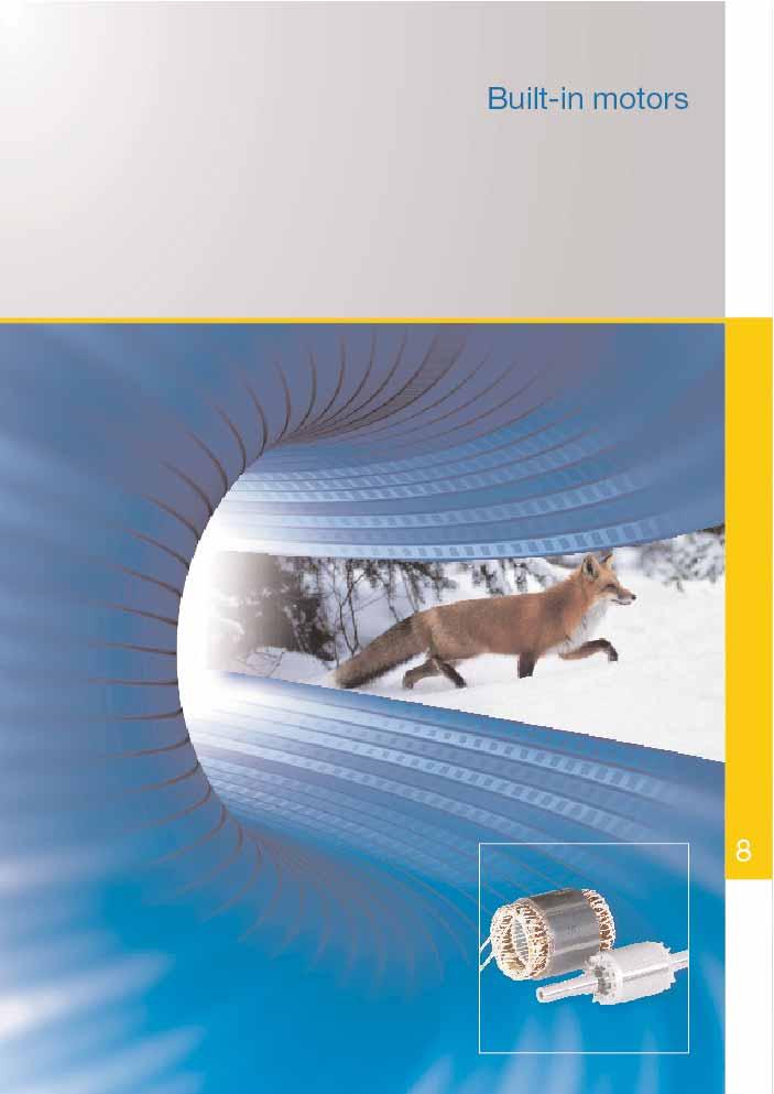
77

78 Built-in motors Built-in motors Basic version General technical data General technical data Motor selection data The most important technical data is summarized in the following table. Detailed information can be found in the catalogue part Technical explanations. Product line Motor with squirrel-cage rotor, IEC/DIN Rated output 0.06 kw to 355 kw Sizes 56 to 355 Material of housing Not applicable, built in component without housing Rated torque 0.25 Nm to 2,400 Nm Types of circuit Motors with one speed are designed with Δ/Y-circuit as standard. Insulation of stator winding Thermal class 155, as option 155 [F(B)], 180 acc. to EN (IEC ) Type of protection IP 00 acc. to EN (IEC ), built-in unit, type of protection realised by customer Type of cooling Undefined, cooling realised by customer Coolant temperature/ as standard - 20 C up to + 40 C, altitude of site altitude of site 1000 m above sea level Rated voltage Rated voltage ranges A and B according to EN (IEC ), standard voltage according to EN Hz, 230 V, 400 V, 500 V and 690 V 60 Hz, 275 V, 480 V and 600 V Types of construction IM 5010 Colour system None Vibration grade Determined by final equipment assembly Shaft end According to DIN 748 (IEC 60072), balancing with half key, only for delivery with complete rotor Limit speeds Please refer to paragraph about limit speeds in the catalogue part Technical explanations. Bearing design Please refer to paragraph about bearings in the catalogue part Technical explanations. Terminal box None Documentation The operation and maintenance manual of the final product is valid. Tolerances Please refer to paragraph about tolerances in the catalogue part Technical explanations. Options Please refer to paragraph about modifications in the catalogue part Technical explanations. LV Asynchronous motors IEC motors with squirrel-cage rotor Main catalogue
79 Built-in motors Built-in motors Three-phase motors with squirrel-cage rotor Built-in motors without shaft Main dimensions for winded stator core Three-phase motors with squirrel-cage rotor Built-in motors without shaft Main dimensions for winded stator core Engineering data selection Engineering data selection Type size 1) d 2) 37 d 37 turn-over dim. +0.6; -0.6 d 41 min. dim. pole number h 37 min. dim. l / -1.0 pole number l 54 max. dim. pole number l 55 max. dim. pole number air gap δ perm. deviation +10%; -10% pole number Type size 4) d d 39 d 40 l 5) l 56 finished dim. 1) delivery dim. delivery dim. 2) finished dim. max. 3) pole number pole number pole number pole number pole number pole number KPR 56 K KPR 56 G KPR 63 K KPR 63 G KPR 71 K KPR 71 G KPR 80 K KPR 80 G KPR 90 L KPR 100 S KPR 100 L KPR 112 M KPR 112 MX KPR 132 S KPR 132 M KPR 160 S KPR 160 M KPR 180 S KPR 180 M KPR 200 M KPR 200 L KPR 225 M KPR 250 S KPR 250 M K10R 280 S K10R 280 M K10R 315 S K10R 315 M K10R 315 L K10R 315 LX K22R 355 MY K22R 355 M KPR 56 K KPR 56 G KPR 63 K KPR 63 G KPR 71 K KPR 71 G KPR 80 K KPR 80 G KPR 90 L KPR 100 S KPR 100 L KPR 112 M KPR 112 MX KPR 132 S KPR 132 M KPR 160 S KPR 160 M KPR 180 S KPR 180 M KPR 200 M KPR 200 L KPR 225 M KPR 250 S KPR 250 M K10R 280 S K10R 280 M K10R 315 S K10R 315 M 6) 6) ) 6) ) 6) ) 6) ) 6) ) 6) K10R 315 L 6) 6) ) 6) ) 6) ) 6) ) 6) ) 6) K10R 315 LX 6) 6) 6) 6) 6) 6) 6) 6) 6) 6) 6) 6) 6) 6) 6) 6) 6) 6) 6) 6) 6) 6) 6) 6) K22R 355 MY 6) 6) 6) 6) 6) 6) 6) 6) 6) 6) 6) 6) 6) 6) 6) 6) 6) 6) 6) 6) 6) 6) 6) 6) K22R 355 M 6) 6) 6) 6) 6) 6) 6) 6) 6) 6) 6) 6) 6) 6) 6) 6) 6) 6) 6) 6) 6) 6) 6) 6) 1) For this size even with different type designation technical characteristics of K20R is realised. 2) Tolerance for mounting hole of the respective grey cast iron stator H7 shaft height 112, P7 shaft height 132, S7 shaft height 160 After pressing the rotor body on the shaft, it has to be turned to finished dimension d 38 and dynamically balanced afterwards. The allowable residual unbalance has to be determined by the user accounting for the requirements of the individual application area Installation of thermocouples on request. 1) Tolerance of finished dimension js8 2) size of knurling and tolerance of the knurled shaft diameter provided by manufacturer 3) maximum permissible core bore (only valid for shafts with knurled seat) 4) For this size even with different type designation technical characteristics of K20R is realised 5) Tolerance +/-0,5 6) Rotor body on request LV Asynchronous motors IEC motors with squirrel-cage rotor Main catalogue
80 Built-in motors Three-phase motors with squirrel-cage rotor with surface ventilation, mode of operation S1, continuous duty thermal class 155 coordination of output Type P B m m Type P B m m stator rotor stator rotor kw kg kg kw kg kg Synchronous speed 3000 rpm 2-pole version Synchronous speed 1500 rpm 4-pole version KPR 56 K2E KPR 56 K4E KPR 56 G2E KPR 56 G4E KPR 63 K2E KPR 63 K4E KPR 63 G2E KPR 63 G4E KPR 71 K2E KPR 71 K4E KPR 71 G2E KPR 71 G4E KPR 80 K2E KPR 80 K4E KPR 80 G2E KPR 80 G4E KPR 90 L2E KPR 90 L4E KPR 100 S2E KPR 100 S4E KPR 100 L2E KPR 100 L4E KPR 112 MY2E KPR 100 LX4E KPR 112 M2E KPR 112 M4E KPR 132 M2E KPR 132 S4E KPR 160 S2E KPR 132 M4E KPR 160 M2E KPR 160 S4E KPR 180 S2E KPR 160 M4E KPR 180 M2E KPR 180 S4E KPR 200 M2E KPR 180 M4E KPR 200 L2E KPR 200 M4E KPR 225 M2E KPR 200 L4E KPR 250 S2E KPR 225 M4E KPR 250 M2E KPR 250 S4E K10R 280 S2E KPR 250 M4E K10R 280 M2E K10R 280 S4E K10R 315 S2E K10R 280 M4E K10R 315 M2E K10R 315 S4E K10R 315 L2E K10R 315 M4E K22R 355 MY2E K10R 315 L4E K22R 355 M2E K22R 355 MY4E Synchronous speed 1000 rpm 6-pole version Synchronous speed 750 rpm 8-pole version KPR 56 K6E KPR 63 K8E KPR 56 G6E KPR 63 G8E KPR 63 K6E KPR 71 K8E KPR 63 G6E KPR 71 G8E KPR 71 K6E KPR 80 K8E KPR 71 G6E KPR 80 G8E KPR 80 K6E KPR 90 L8E KPR 80 G6E KPR 100 S8E KPR 90 L6E KPR 100 L8E KPR 100 L6E KPR 112 M8E KPR 112 M6E KPR 112 MX8E KPR 112 MX6E KPR 132 S8E KPR 132 S6E KPR 132 M8E KPR 132 M6E KPR 160 S8E KPR 160 S6E KPR 160 M8E KPR 160 M6E KPR 180 S8E KPR 180 S6E KPR 180 M8E KPR 180 M6E KPR 200 M8E KPR 200 M6E KPR 225 M8E KPR 225 M6E KPR 250 S8E KPR 250 S6E KPR 250 M8E KPR 250 M6E K10R 280 S8E K10R 280 S6E K10R 280 M8E K10R 280 M6E K10R 315 S8E K10R 315 S6E K10R 315 M8E K10R 315 M6E K10R 315 L8E K10R 315 L6E K10R 315 LX8E K10R 315 LX6E K22R 355 MY8E K22R 355 MY6E K22R 355 M8E K22R 355 M6E Output data subject to the mounting and cooling conditions Mass of rotor without shaft 150
81
82 Dimensions Dimensions Dimensions Flange sizes Flange coordination Flange dimensions Flanges with threadholes Flange type acc. to EN Flange type acc. to DIN LA M N P S T c 1 e 1 b 1 a 1 s 1 f 1 Basic version IEC/DIN Cooling method IC 411 Transnorm version Cooling method IC 411 Energy saving motors CEMEP Energy saving motors EPAct Non-ventilated motors, cooling method IC 410 IEC/DIN version Non-ventilated motors, cooling method IC 410 Transnorm version Forced-ventilated motors, cooling method IC 416 IEC/DIN version FT 65 C M5 2.5 FT 75 C M5 2.5 FT 85 C M6 2.5 FT 100 C M6 3 FT 115 C M8 3 FT 130 C M8 3.5 FT 165 C M FT 215 C M12 4 Flanges with through holes Flange type acc. to EN Flange type acc. to DIN LA M N P S T c 1 e 1 b 1 a 1 s 1 f 1 FF 100 A FF 115 A FF 130 A FF 165 A FF 215 A FF 265 A FF 300 A FF 350 A FF 400 A FF 500 A FF 600 A FF 740 A According to EN the flanges FF have through holes and the flanges FT have threadholes. The standard DIN for flanges A and C are still valid yet. If non-standard coordinations of flange types are required, see flange coordination tables of this catalogue. Tolerances for dimension N (b 1 ) see respective dimensional tables LA (c 1 ) length of engagement Forced-ventilated motors, cooling method IC 416 Transnorm version Notes to dimensions Dimensional designations according to EN and IEC Flange sizes in the dimensional tables are given in accordance to DIN All dimensional data in mm VEM motors GmbH reserves the right to change technical data without preceding information. Dimensional data in catalogues can lose their validity. Binding dimensional data can be requested from the VEM sales organisations
83 Dimensions Dimensions Flange versions Type of construction IM B5 / IM 3001 Flange versions Type of construction IM 2202 K20R KPR S 315M K20R KPR S 315M K21R, K22R KPER K11R LX M4, MX M4, L6, L, LX6 200LX S, M 315MX 315MY, L, LX 355M, MY, L K21R, K22R KPER K11R LX M4, MX M4, L6, L, LX6 200LX S, M 315MX Dinmm D in mm P a ) 120 1) 120 1) 120 1) 120 1) N b ) protruding flange M e S s P a ) 140 1) N b M e S s P a ) 160 1) 160 1) 160 1) 160 1) 160 1) 160 1) 160 1) N b M e S s P a ) 200 1) 200 1) 200 1) N b M e S s P a 1 250* 250* ) 250 1) 250 1) N b M e S s P a ) 300 1) 300 1) 300 1) 300 1) ) 300 3) 2) Customer's flange fixing only by studs N b ) for shaft end diameter 42 mm: customer's M e flange fixing only by studs S s P a N b M e S s P a ) 400 4) ) 4) KPR flange (with corners) N b ) for shaft end M e diameter 50 mm S s P a N b M e S s P a 1 5) not for high radial loads ) N b 1 cylindrical roller bearing NU M e 1 not usable S s P a N b M e S s P a N b M e S s 1 22 Flange versions IM B5 P a N b M e S s P a N b M e S s P a N b M e S s P a N b M e S s P a N b M e S s Flange versions Type of construction IM B14 K, G K21R, K22R KPER K11R 63 K20R KPR LX D in mm P a N b M e S s 1 M5 M5 M6 P a N b M e S s 1 M5 M6 M6 M6 M8 P a ) ) ) protruding flange N b M e S s 1 M6 M6 M8 M8 M8 M8 M8 M8 M8 P a N b M e S s 1 M6 M8 M8 M8 M10 M10 M10 M10 M10 M12 M12 M12 M M4, MX6 315MY, L, LX 355M, MY, L Flange versions IM 2202 and IM B M4, L6, L, LX LX S, M MX 315S 315MY, L, LX 315M 355M, MY, L
84 Dimensions Dimensions Three-phase motors with squirrel-cage rotor, basic version Three-phase motors with squirrel-cage rotor, basic version Size 56 to 280 with surface ventilation, cooling method IC 411, degree of protection P 55 Type of construction IM B3 [IM 1001] Size 56 to 280 with surface ventilation, cooling method IC 411, degree of protection P 55 Type of construction IM B35 [IM 2001] Flange dimensions see page 154/155 Type designation Flange A AA AB AC AD B BA BB C CA D DA DB*) E EA F FA size b n f g g1 a m e w1 w2 d d1 l l1 u u1 Type designation GA GC H HA HD HD**) HH K K L LC KK Type AG LL O Hole BI. t t1 h c p p A s s k k1 pattern Bl K21O 56K2,4 FF M K21R 56G2,4 FF M K21R 63K2,4,6 FF M K21R 63G2,4,6 FF M K21R 71K2,4,6,8 FF M K21R 71G2,4,6,8 FF M K21R 80K2,4,6,8 FF M K21R 80G2,4,6,8 FF M K21R 90S2,4,6,8 FF M K21R 90L2,4,6,8 FF M K21R 100L2,4,6,8 FF M K21R 100LX4,8 FF M K21R 112M2 FF M K21R 112M6,8 FF M K21R 112MX2 FF M K21R 112M4 FF M K21R 132S2T FF M K21R 132S4T FF M K21R 132S2 FF M K21R 132SX2 FF M K21R 132S4,6,8 FF M K21R 132M4 FF M K21R 132MX6 FF M K21R 132M6.8 FF M K21R 160M2 FF M K21R 160M4,6,8 FF M K21R 160MX8 FF M K21R 160MX2 FF M K21R 160L2,4,6,8 FF M K21R 180M2 FF M K21R 180M4 FF M K21R 180L4 FF M K21R 180L6,8 FF M K21R 200L2,4,6,8 FF M K21R 200LX6 FF M K21R 200LX2 FF M K21R 225S4,8 FF M K21R 225M2 FF M K21R 225M4 FF M K21R 225M6,8 FF M K21R 250M2 FF M K21R 250M4,6,8 FF M K21R 280S2 FF M K21R 280S4,6,8 FF M K21R 280M2 FF M K21R 280M4,6,8 FF M *) Centre holes acc. to DIN 332-DS K21O 56K2, a.a KA M20x1.5 4L 14 K21R 56G2, a.a KA M20x1.6 4L 14 K21R 63K2,4, a.a KA M20x1.5 4L 14 K21R 63G2,4, a.a KA M20x1.5 4L 14 K21R 71K2,4,6, a.a KA M20x1.5 4L 14 K21R 71G2,4,6, a.a KA M20x1.5 4L 14 K21R 80K2,4,6, a.a KA M20x1.5 4L 16 K21R 80G2,4,6, a.a KA M20x1.5 4L 16 K21R 90S2,4,6, a.a KA M25x1.5 4L 16 K21R 90L2,4,6, a.a KA M25x1.5 4L 16 K21R 100L2,4,6, a.a KA M25x1.5 4L 18 K21R 100LX4, a.a KA M25x1.5 4L 20 K21R 112M a.a KA M25x1.5 4L 20 K21R 112M6, a.a KA M25x1.5 4L 20 K21R 112MX a.a KA M25x1.5 4L 20 K21R 112M a.a KA M25x1.5 4L 20 K21R 132S2T a.a KA M25x1.5 4L 20 K21R 132S4T a.a KA M25x1.5 4L 20 K21R 132S KK 25 A M32x1.5 4L 35 K21R 132SX KK 25 A M32x1.5 4L 35 K21R 132S4,6, KK 25 A M32x1.5 4L 35 K21R 132M KK 25 A M32x1.5 4L 35 K21R 132MX KK 25 A M32x1.5 4L 35 K21R 132M6, KK 25 A M32x1.5 4L 35 K21R 160M KK 63 A M40x1.5 4L 35 K21R 160M4,6, KK 63 A M40x1.5 4L 35 K21R 160MX KK 63 A M40x1.5 4L 35 K21R 160MX KK 63 A M40x1.5 4L 35 K21R 160L2,4,6, KK 63 A M40x1.5 4L 35 K21R 180M KK 63 A M40x1.5 4L 35 K21R 180M KK 63 A M40x1.5 4L 35 K21R 180L KK 63 A M40x1.5 4L 35 K21R 180L6, KK 63 A M40x1.5 4L 35 K21R 200L2,4,6, KK 63 A M40x1.5 4L 35 K21R 200LX KK 63 A M40x1.5 4L 35 K21R 200LX KK 100 A M50x1.5 4L 35 K21R 225S4, KK 100 A M50x1.5 8L 40 K21R 225M KK 100 A M50x1.5 8L 40 K21R 225M KK 100 A M50x1.5 8L 40 K21R 225M6, KK 100 A M50x1.5 8L 40 K21R 250M KK 200 A M63x1.5 8L 45 K21R 250M4,6, KK 200 A M63x1.5 8L 45 K21R 280S KK 200 A M63x1.5 8L 50 K21R 280S4,6, KK 200 A M63x1.5 8L 50 K21R 280M KK 200 A M63x1.5 8L 50 K21R 280M4,6, KK 200 A M63x1.5 8L 50 **) Terminal box left/right


85 Dimensions Dimensions Three-phase motors with squirrel-cage rotor, basic version Three-phase motors with squirrel-cage rotor, basic version Size 315 with surface ventilation, cooling method IC 411, degree of protection P 55 Type of construction IM B3 [IM 1001] Size 315 with surface ventilation, cooling method IC 411, degree of protection P 55 Type of construction IM B35 [IM 2001] Flange dimensions see page 154/155 Type designation Flange A AA AB AC AD B BA BA BB C CA D DA DB*) E EA F FA size b n f g g1 a m m1 e w1 w2 d d1 l l1 u u1 Type designation GA GC H HA HD HD**) HH K K L LC KK Type AG LL AH O Bl. t t1 h c p p A s s k k1 - x z - r Bl K21R 315S2 FF M K21R 315S4,6,8 FF M K21R 315M2 FF M K21R 315M4,6,8 FF M K21R 315MX2 FF M K21R 315MX4 FF M K21R 315MX6,8 FF M K21R 315MX10,12 FF M K21R 315MY2 FF M K21R 315MY4,6,8 FF M K21R 315L2 FF M K21R 315L4,6,8 FF M K21R 315LX2 FF M K21R 315LX4 FF M K21R 315LX6,8 FF M *) Centre holes acc. to DIN 332-DS K21R 315S KK 200 A M63x K21R 315S4,6, KK 200 A M63x K21R 315M KK 200 A M63x K21R 315M4,6, KK 200 A M63x K21R 315MX KK 200 A M63x K21R 315MX KK 200 A M63x K21R 315MX6, KK 200 A M63x K21R 315MX10, KK 200 A M63x K21R 315MY KK 400 B M63x K21R 315MY4,6, KK 400 B M63x K21R 315L KK 400 B M63x K21R 315L4,6, KK 400 B M63x K21R 315LX KK 400 B M63x K21R 315LX KK 400 B M63x K21R 315LX6, KK 400 B M63x **) Terminal box left/right

![of construction IM B14 [IM 3601] Flange dimensions see page 154/155 Type designation Flange sizes A AA AB AC AD B BA BB C CA D DA DB*) E EA F FA small big b n f g g1 a m e w1 w2 d d1 l l1 u u1 Type](/docs-images/72/66915654/images/86-1.jpg "designation GA GC H HA HD HD**) HH K K L LC KK Type AG LL O Hole Bl. t t1 h c p p A s s k k1 - x z r pattern Bl.")


86 Dimensions Dimensions Three-phase motors with squirrel-cage rotor, basic version Three-phase motors with squirrel-cage rotor, basic version Size 56 to 180 with surface ventilation, cooling method IC 411, degree of protection P 55 Type of construction IM B34 [IM 2101] Flange dimensions see page 154/155 Size 56 to 180 with surface ventilation, cooling method IC 411, degree of protection P 55 Type of construction IM B14 [IM 3601] Flange dimensions see page 154/155 Type designation Flange sizes A AA AB AC AD B BA BB C CA D DA DB*) E EA F FA small big b n f g g1 a m e w1 w2 d d1 l l1 u u1 Type designation GA GC H HA HD HD**) HH K K L LC KK Type AG LL O Hole Bl. t t1 h c p p A s s k k1 - x z r pattern Bl. K21O 56K2,4 FT 65 FT M K21R 56G2,4 FT M K21R 63K2,4,6 FT 75 FT M K21R 63G2,4,6 FT 75 FT M K21R 71K2,4,6,8 FT 85 FT , M K21R 71G2,4,6,8 FT 85 FT , M K21R 80K2,4,6,8 FT 100 FT M K21R 80G2,4,6,8 FT 100 FT M K21R 90S2,4,6,8 FT 115 FT M K21R 90L2,4,6,8 FT 115 FT M K21R 100L2,4,6,8 FT 130 FT M K21R 100LX4,8 FT 130 FT M K21R 112M2 FT 130 FT M K21R 112M6,8 FT 130 FT M K21R 112MX2 FT 130 FT M K21R 112M4 FT 130 FT M K21R 132S2T FT 130 FT M K21R 132S4T FT 130 FT M K21R 132S2 FT 130 FT M K21R 132SX2 FT 130 FT M K21R 132S4,6,8 FT 130 FT M K21R 132M4 FT 165 FT M K21R 132MX6 FT 165 FT M K21R 132M6,8 FT 130 FT M K21R 160M2 FT 165 FT M K21R 160M4,6,8 FT 165 FT M K21R 160MX8 FT 165 FT M K21R 160MX2 FT 215 FT M K21R 160L2,4,6,8 FT 215 FT M K21R 180M4 FT M K21R 180L6,8 FT M *) Centre holes acc. to DIN 332-DS K21O 56K2,4 10, a.a KA M20x1.5 4L 14 K21R 56G2, a.a KA M20x1.5 4L 14 K21R 63K2,4, a.a KA M20x1.5 4L 14 K21R 63G2,4, a.a KA M20x1.5 4L 14 K21R 71K2,4,6, a.a KA M20x1.5 4L 14 K21R 71G2,4,6, a.a KA M20x1.5 4L 14 K21R 80K2,4,6, a.a KA M20x1.5 4L 16 K21R 80G2,4,6, a.a KA M20x1.5 4L 16 K21R 90S2,4,6, a.a KA M25x1.5 4L 16 K21R 90L2,4,6, a.a KA M25x1.5 4L 16 K21R 100L2,4,6, a.a KA M25x1.5 4L 18 K21R 100LX4, a.a KA M25x1.5 4L 20 K21R 112M a.a KA M25x1.5 4L 20 K21R 112M6, a.a KA M25x1.5 4L 20 K21R 112MX a.a KA M25x1.5 4L 20 K21R 112M a.a KA M25x1.5 4L 20 K21R 132S2T a.a KA M25x1.5 4L 20 K21R 132S4T a.a KA M25x1.5 4L 20 K21R 132S KK 25 A M32x1.5 4L 35 K21R 132SX KK 25 A M32x1.5 4L 35 K21R 132S4,6, KK 25 A M32x1.5 4L 35 K21R 132M KK 25 A M32x1.5 4L 35 K21R 132MX KK 25 A M32x1.5 4L 35 K21R 132M6, KK 25 A M32x1.5 4L 35 K21R 160M KK 63 A M40x1.5 4L 35 K21R 160M4,6, KK 63 A M40x1.5 4L 35 K21R 160MX KK 63 A M40x1.5 4L 35 K21R 160MX KK 63 A M40x1.5 4L 35 K21R 160L2,4,6, KK 63 A M40x1.5 4L 35 K21R 180M KK 63 A M40x1.5 4L 35 K21R 180L6, KK 63 A M40x1.5 4L 35 **) Terminal box left/right
87 Dimensions Dimensions Three-phase motors with squirrel-cage rotor, basic version Size 56 to 280 with surface ventilation, cooling method IC 411, degree of protection P 55 Type of construction IM B5 [IM 3001] Type of construction IM V1 [IM 3011] Flange dimensions see page 154/155 Three-phase motors with squirrel-cage rotor, basic version Size 315 with surface ventilation, cooling method IC 411, degree of protection P 55 Type of construction IM B5 [IM 3001] up to size 315MY Type of construction IM V1 [IM 3011] Flange dimensions see page 154/155 Type designation Flange AC AD D DA DB*) E EA F FA GA GC H HH L LC KK Type AG LL O Hole BI. size g g1 d d1 l l1 u u1 t t1 h A k k1 pattern Bl K21O 56K2,4 FF M KA M20x1.5 4L 14 K21R 56G2,4 FF M KA M20x1.6 4L 14 K21R 63K2,4,6 FF M KA M20x1.5 4L 14 K21R 63G2,4,6 FF M KA M20x1.5 4L 14 K21R 71K2,4,6,8 FF M KA M20x1.5 4L 14 K21R 71G2,4,6,8 FF M KA M20x1.5 4L 14 K21R 80K2,4,6,8 FF M KA M20x1.5 4L 16 K21R 80G2,4,6,8 FF M KA M20x1.5 4L 16 K21R 90S2,4,6,8 FF M KA M25x1.5 4L 16 K21R 90L2,4,6,8 FF M KA M25x1.5 4L 16 K21R 100L2,4,6,8 FF M KA M25x1.5 4L 18 K21R 100LX4,8 FF M KA M25x1.5 4L 20 K21R 112M2 FF M KA M25x1.5 4L 20 K21R 112M6,8 FF M KA M25x1.5 4L 20 K21R 112MX2 FF M KA M25x1.5 4L 20 K21R 112M4 FF M KA M25x1.5 4L 20 K21R 132S2T FF M KA M25x1.5 4L 20 K21R 132S4T FF M KA M25x1.5 4L 20 K21R 132S2 FF M KK 25 A M32x1.5 4L 35 K21R 132SX2 FF M KK 25 A M32x1.5 4L 35 K21R 132S4,6,8 FF M KK 25 A M32x1.5 4L 35 K21R 132M4 FF M KK 25 A M32x1.5 4L 35 K21R 132MX6 FF M KK 25 A M32x1.5 4L 35 K21R 132M6,8 FF M KK 25 A M32x1.5 4L 35 K21R 160M2 FF M KK 63 A M40x1.5 4L 35 K21R 160M4,6,8 FF M KK 63 A M40x1.5 4L 35 K21R 160MX8 FF M KK 63 A M40x1.5 4L 35 K21R 160MX2 FF M KK 63 A M40x1.5 4L 35 K21R 160L2,4,6,8 FF M KK 63 A M40x1.5 4L 35 K21R 180M2 FF M KK 63 A M40x1.5 4L 35 K21R 180M4 FF M KK 63 A M40x1.5 4L 35 K21R 180L4 FF M KK 63 A M40x1.5 4L 35 K21R 180L6,8 FF M KK 63 A M40x1.5 4L 35 K21R 200L2,4,6,8 FF M KK 63 A M40x1.5 4L 35 K21R 200LX6 FF M KK 63 A M40x1.5 4L 35 K21R 200LX2 FF M KK 100 A M50x1.5 4L 35 K21R 225S4,8 FF M KK 100 A M50x1.5 8L 40 K21R 225M2 FF M KK 100 A M50x1.5 8L 40 K21R 225M4 FF M KK 100 A M50x1.5 8L 40 K21R 225M6,8 FF M KK 100 A M50x1.5 8L 40 K21R 250M2 FF M KK 200 A M63x1.5 8L 45 K21R 250M4,6,8 FF M KK 200 A M63x1.5 8L 45 K21R 280S2 FF M KK 200 A M63x1.5 8L 50 K21R 280S4,6,8 FF M KK 200 A M63x1.5 8L 50 K21R 280M2 FF M KK 200 A M63x1.5 8L 50 K21R 280M4,6,8 FF M KK 200 A M63x1.5 8L 50 *) Centre holes acc. to DIN 332-DS **) Terminal box left/right Type designation Flange AC AD D DA DB*) E EA F FA GA GC H HH L LC KK Type AG LL AH O Bl. size g g1 d d1 l l1 u u1 t t1 h A k k1 x z - r Bl K21R 315S2 FF M KK 200 A M63x K21R 315S4,6,8 FF M KK 200 A M63x K21R 315M2 FF M KK 200 A M63x K21R 315M4,6,8 FF M KK 200 A M63x K21R 315MX2 FF M KK 200 A M63x K21R 315MX4 FF M KK 200 A M63x K21R 315MX6,8 FF M KK 200 A M63x K21R 315MX10,12 FF M KK 200 A M63x K21R 315MY2 FF M KK 400 B M63x K21R 315MY4,6,8 FF M KK 400 B M63x K21R 315L2 FF M KK 400 B M63x K21R 315L4,6,8 FF M KK 400 B M63x K21R 315LX2 FF M KK 400 B M63x K21R 315LX4 FF M KK 400 B M63x K21R 315LX6,8 FF M KK 400 B M63x *) Centre holes acc. to DIN 332-DS **) Terminal box left/righ
88 Dimensions Dimensions Three-phase motors with squirrel-cage rotor, basic version Size 355 with surface ventilation, cooling method IC 411, degree of protection P 55 Type of construction IM B3 [IM 1001] Three-phase motors with squirrel-cage rotor, basic version Size 355 with surface ventilation, cooling method IC 411, degree of protection P 55 Type of construction IM V1 [IM 3011] Flange dimensions see page 154/155 Type of construction IM B35 [IM 2001] Flange dimensions see page 154/155 Type designation Flange AC AD AD**) D DA DB*) E EA F FA GA GC H HH L LC KK Type AG LL AH BE O Bl. size g g1 g1 d d1 l l1 u u1 t t1 h A k k1 x z - - r Bl K22R 355MY2,M2 FF M KK 630 A M72x2 60 K22R 355MY4,6,8 FF M KK 630 A M72x2 60 K22R 355M4 FF M KK 630 A M72x2 60 K22R 355M6,8 FF M KK 630 A M72x2 60 K22R 355MX6,8 FF M KK 630 A M72x2 60 K22R 355MX2 FF M KK 1000 A M72x2 60 K22R 355LY2,L2 FF M KK 1000 A M72x2 60 K22R 355MX4 FF M KK 1000 A M72x2 60 K22R 355LY4,6,8,L4 FF M KK 1000 A M72x2 60 *) Centre holes acc. to DIN 332-DS **) Terminal box left/right Type designation Flange A AA AB AC B BA BA BB C CA D DA DB*) E EA F FA size b n f g a m m1 e w1 w2 d d1 l l1 u u1 K22R 355MY2,M2 FF M K22R 355MY4,6,8 FF M K22R 355M4 FF M K22R 355M6,8 FF M K22R 355MX6,8 FF M K22R 355MX2 FF M K22R 355LY2,L2 FF M K22R 355MX4 FF M K22R 355LY4,6,8,L4 FF M Type designation GA GC H HA HD HD**) HH K K L LC KK Type AG LL AH BE O Bl. t t1 h c p p A s s k k1 x z - - r Bl K22R 355MY2,M KK 630 A M72x2 60 K22R 355MY4,6, KK 630 A M72x2 60 K22R 355M KK 630 A M72x2 60 K22R 355M6, KK 630 A M72x2 60 K22R 355MX6, KK 630 A M72x2 60 K22R 355MX KK 1000 A M72x2 60 K22R 355LY2,L KK 1000 A M72x2 60 K22R 355MX KK 1000 A M72x2 60 K22R 355LY4,6,8,L KK 1000 A M72x2 60 *) Centre holes acc. to DIN 332-DS **) Terminal box left/right

89 Dimensions Dimensions Three-phase motors with squirrel-cage rotor, basic version, transnorm version Size 56 to 250 with surface ventilation, cooling method IC 411, degree of protection P 55 Type of construction IM B3 [IM 1001] Three-phase motors with squirrel-cage rotor, basic version, transnorm version Type of construction IM B35 [IM 2001] Flange dimensions see page 154/155 Size 112 to 160 with crowned flange Type designation Flange A AA AB AC AD B BA BB C CA D DA DB*) E EA F FA size b n f g g1 a m e w1 w2 d d1 l l1 u u1 Type designation GA GC H HA HD HD**) HH K K L LC KK Type AG LL O Hole BI. t t1 h c p p A s s k k1 pattern Bl K20R 56K FF M K20R 56G FF M K20R 63K FF M K20R 63G FF M K20R 71K FF M K20R 71G FF M K20R 80K FF M K20R 80G FF M K20R 90L FF M K20R 100S FF M K20R 100L2,4 FF M K20R 100L6,8 FF M K20R 100LX4 FF M K20R 112M2 FF M K20R 112M4,6,8 FF M K20R 112MX6,8 FF M K20R 132S FF M K20R 132M FF M K20R 160S2 FF M K20R 160S4,6,8 FF M K20R 160M2 FF M K20R 160M4,6,8 FF M K20R 180S2 FF M K20R 180S4,6,8 FF M K20R 180M2 FF M K20R 180M4,6,8 FF M K20R 200M2 FF M K20R 200M4,6,8 FF M K20R 200L2 FF M K20R 200L4,6,8 FF M K20R 225M2 FF M K20R 225M4,6,8 FF M K20R 250S2 FF M K20R 250S4,6,8 FF M K20R 250M2 FF M K20R 250M4,6,8 FF M *) Centre holes acc. to DIN 332-DS K20R 56K a.a KA M20x1.5 4L 14 K20R 56G a.a KA M20x1.5 4L 14 K20R 63K a.a KA M20x1.5 4L 14 K20R 63G a.a KA M20x1.5 4L 14 K20R 71K a.a KA M20x1.5 4L 16 K20R 71G a.a KA M20x1.5 4L 16 K20R 80K a.a KA M20x1.5 4L 16 K20R 80G a.a KA M20x1.5 4L 16 K20R 90L ,5 217 a.a KA M20x1.5 4L 18 K20R 100S a.a KA M20x1.5 4L 20 K20R 100L2, a.a KA M20x1.5 4L 20 K20R 100L6, a.a KA M20x1.5 4L 20 K20R 100LX a.a KA M20x1.5 4L 20 K20R 112M a.a KK 25 A M32x1.5 4L 35 K20R 112M4,6, a.a KK 25 A M32x1.5 4L 35 K20R 112MX6, a.a KK 25 A M32x1.5 4L 35 K20R 132S a.a KK 25 A M32x1.5 4L 35 K20R 132M a.a KK 25 A M32x1.5 4L 35 K20R 160S a.a KK 63 A M40x1.5 4L 35 K20R 160S4,6, a.a KK 63 A M40x1.5 4L 35 K20R 160M a.a KK 63 A M40x1.5 4L 35 K20R 160M4,6, a.a KK 63 A M40x1.5 4L 35 K20R 180S a.a KK 63 A M40x1.5 4L 35 K20R 180S4,6, a.a KK 63 A M40x1.5 4L 35 K20R 180M a.a KK 63 A M40x1.5 4L 35 K20R 180M4,6, a.a KK 63 A M40x1.5 4L 35 K20R 200M a.a KK 100 A M50x1.5 4L 40 K20R 200M4,6, a.a KK 100 A M50x1.5 4L 40 K20R 200L a.a KK 100 A M50x1.5 4L 40 K20R 200L4,6, a.a KK 100 A M50x1.5 4L 40 K20R 225M a.a KK 100 A M50x1.5 8L 45 K20R 225M4,6, a.a KK 100 A M50x1.5 8L 45 K20R 250S a.a KK 200 A M63x1.5 8L 50 K20R 250S4,6, a.a KK 200 A M63x1.5 8L 50 K20R 250M a.a KK 200 A M63x1.5 8L 50 K20R 250M4,6, a.a KK 200 A M63x1.5 8L 50 **) Terminal box left/right

![Type of construction IM B35 [IM 2001] Flange dimensions see page 154/155 Type designation Flange A AA AB AC AD B BA BA BB C CA D DA DB*) E EA F FA size b n f g g1 a m m1 e w1 w2 d d1 l l1 u u1 Type](/docs-images/72/66915654/images/90-1.jpg "designation GA GC H HA HD HD**) HH K K L LC KK Type AG LL AH O Bl.")
90 Dimensions Dimensions Three-phase motors with squirrel-cage rotor, basic version, transnorm version Three-phase motors with squirrel-cage rotor, basic version, transnorm version Size 280, 315 with surface ventilation, cooling method IC 411, degree of protection P 55 Type of construction IM B3 [IM 1001] Size 280, 315 with surface ventilation, cooling method IC 411, degree of protection P 55 Type of construction IM B35 [IM 2001] Flange dimensions see page 154/155 Type designation Flange A AA AB AC AD B BA BA BB C CA D DA DB*) E EA F FA size b n f g g1 a m m1 e w1 w2 d d1 l l1 u u1 Type designation GA GC H HA HD HD**) HH K K L LC KK Type AG LL AH O Bl. t t1 h c p p A s s k k1 x z - r Bl K20R 280S2 FF M K20R 280S4,6,8 FF M K20R 280M2 FF M K20R 280M4,6,8 FF M K20R 315S2 FF M K20R 315S4 FF M K20R 315S6,8 FF M K20R 315M2 FF M K20R 315M4,6,8 FF M K20R 315M10,12 FF M K20R 315L2 FF M K20R 315L4,6,8 FF M K20R 315LX2 FF M K20R 315LX4 FF M K20R 315LX6,8 FF M *) Centre holes acc. to DIN 332-DS K20R 280S a.a KK 200 A M63x K20R 280S4,6, a.a KK 200 A M63x K20R 280M a.a KK 200 A M63x K20R 280M4,6, a.a KK 200 A M63x K20R 315S a.a KK 200 A M63x K20R 315S a.a KK 200 A M63x K20R 315S6, a.a KK 200 A M63x K20R 315M a.a KK 400 B M63x K20R 315M4,6, a.a KK 400 B M63x K20R 315M10, a.a KK 400 B M63x K20R 315L a.a KK 400 B M63x K20R 315L4,6, a.a KK 400 B M63x K20R 315LX a.a KK 400 B M63x K20R 315LX a.a KK 400 B M63x K20R 315LX6, a.a KK 400 B M63x **) Terminal box left/right

91 Dimensions Dimensions Three-phase motors with squirrel-cage rotor, basic version, transnorm version Three-phase motors with squirrel-cage rotor, basic version, transnorm version Size 56 to 160 with surface ventilation, cooling method IC 411, degree of protection P 55 Type of construction IM B34 [IM 2101] Flange dimensions see page 154/155 Size 56 to 160 with surface ventilation, cooling method IC 411, degree of protection P 55 Type of construction IM B14 [IM 3601] Flange dimensions see page 154/155 Type designation Flange sizes A AA AB AC AD B BA BB C CA D DA DB*) E EA F FA small big b n f g g1 a m e w1 w2 d d1 l l1 u u1 Type designation GA GC H HA HD HD**) HH K K L LC KK Type AG LL O Hole Bl. t t1 h c p p A s s k k1 pattern Bl. K20R 56K FT 65 FT M K20R 56G FT 65 FT M K20R 63K FT 75 FT M K20R 63G FT 75 FT M K20R 71K FT 85 FT M K20R 71G FT 85 FT M K20R 80K FT 100 FT M K20R 80G FT 100 FT M K20R 90L FT 115 FT M K20R 100S FT 130 FT M K20R 100L2,4 FT 130 FT M K20R 100L6,8 FT 130 FT M K20R 100LX4 FT 130 FT M K20R 112M2 FT 130 FT M K20R 112M4,6,8 FT 130 FT M K20R 112MX6,8 FT 130 FT M K20R 132S FT 165 FT M K20R 132M FT 165 FT M K20R 160S2 FT 215 FT M K20R 160S4,6,8 FT 215 FT M K20R 160M2 FT 215 FT M K20R 160M4,6,8 FT 215 FT M *) Centre holes acc. to DIN 332-DS K20R 56K a.a KA M20x1.5 4L 14 K20R 56G a.a KA M20x1.5 4L 14 K20R 63K a.a KA M20x1.5 4L 14 K20R 63G a.a KA M20x1.5 4L 14 K20R 71K a.a KA M20x1.5 4L 16 K20R 71G a.a KA M20x1.5 4L 16 K20R 80K a.a KA M25x1.5 4L 16 K20R 80G a.a KA M25x1.5 4L 16 K20R 90L a.a KA M25x1.5 4L 18 K20R 100S a.a KA M25x1.5 4L 20 K20R 100L2, a.a KA M25x1.5 4L 20 K20R 100L6, a.a KA M25x1.5 4L 20 K20R 100LX a.a KA M25x1.5 4L 20 K20R 112M a.a KK 25 A M32x1.5 4L 35 K20R 112M4,6, a.a KK 25 A M32x1.5 4L 35 K20R 112MX6, a.a KK 25 A M32x1.5 4L 35 K20R 132S a.a KK 25 A M32x1.5 4L 35 K20R 132M a.a KK 25 A M32x1.5 4L 35 K20R 160S a.a KK 63 A M40x1.5 4L 35 K20R 160S4,6, a.a KK 63 A M40x1.5 4L 35 K20R 160M a.a KK 63 A M40x1.5 4L 35 K20R 160M4,6, a.a KK 63 A M40x1.5 4L 35 **) Terminal box left/right

![surface ventilation, cooling method IC 411, degree of protection P 55 Type of construction IM B5 [IM 3001] up to size 315M Type of construction IM V1 [IM 3011] Flange dimensions see page 154/155 Size](/docs-images/72/66915654/images/92-1.jpg "160 with crowned flange Type designation Flange AC AD D DA DB*) E EA F FA GA GC H HH L LC KK Type AG LL O Hole BI.")

92 Dimensions Dimensions Three-phase motors with squirrel-cage rotor, basic version, transnorm version Size 56 to 250 with surface ventilation, cooling method IC 411, degree of protection P 55 Type of construction IM B5 [IM 3001] Type of construction IM V1 [IM 3011] Flange dimensions see page 154/155 Three-phase motors with squirrel-cage rotor, basic version, transnorm version Size 280, 315 with surface ventilation, cooling method IC 411, degree of protection P 55 Type of construction IM B5 [IM 3001] up to size 315M Type of construction IM V1 [IM 3011] Flange dimensions see page 154/155 Size 160 with crowned flange Type designation Flange AC AD D DA DB*) E EA F FA GA GC H HH L LC KK Type AG LL O Hole BI. size g g1 d d1 l l1 u u1 t t1 h A k k1 pattern Bl Type designation Flange AC AD D DA DB*) E EA F FA GA GC H HH L LC KK Type AG LL AH O Bl. size g g1 d d1 l l1 u u1 t t1 h A k k1 x z - r Bl K20R 56K FF M KA M20x1.5 4L 14 K20R 56G FF M KA M20x1.5 4L 14 K20R 63K FF M KA M20x1.5 4L 14 K20R 63G FF M KA M20x1.5 4L 14 K20R 71K FF M KA M20x1.5 4L 16 K20R 71G FF M KA M20x1.5 4L 16 K20R 80K FF M KA M20x1.5 4L 16 K20R 80G FF M KA M20x1.5 4L 16 K20R 90L FF M KA M20x1.5 4L 18 K20R 100S FF M KA M20x1.5 4L 20 K20R 100L2,4 FF M KA M20x1.5 4L 20 K20R 100L6,8 FF M KA M20x1.5 4L 20 K20R 100LX4 FF M KA M20x1.5 4L 20 K20R 112M2 FF M KK 25 A M32x1.5 4L 35 K20R 112M4,6,8 FF M KK 25 A M32x1.5 4L 35 K20R 112MX6,8 FF M KK 25 A M32x1.5 4L 35 K20R 132S FF M KK 25 A M32x1.5 4L 35 K20R 132M FF M KK 25 A M32x1.5 4L 35 K20R 160S2 FF M KK 63 A M40x1.5 4L 35 K20R 160S4,6,8 FF M KK 63 A M40x1.5 4L 35 K20R 160M2 FF M KK 63 A M40x1.5 4L 35 K20R 160M4,6,8 FF M KK 63 A M40x1.5 4L 35 K20R 180S2 FF M KK 63 A M40x1.5 4L 35 K20R 180S4,6,8 FF M KK 63 A M40x1.5 4L 35 K20R 180M2 FF M KK 63 A M40x1.5 4L 35 K20R 180M4,6,8 FF M KK 63 A M40x1.5 4L 35 K20R 200M2 FF M KK 100 A M50x1.5 4L 40 K20R 200M4,6,8 FF M KK 100 A M50x1.5 4L 40 K20R 200L2 FF M KK 100 A M50x1.5 4L 40 K20R 200L4,6,8 FF M KK 100 A M50x1.5 4L 40 K20R 225M2 FF M KK 100 A M50x1.5 8L 45 K20R 225M4,6,8 FF M KK 100 A M50x1.5 8L 45 K20R 250S2 FF M KK 200 A M63x1.5 8L 50 K20R 250S4,6,8 FF M KK 200 A M63x1.5 8L 50 K20R 250M2 FF M KK 200 A M63x1.5 8L 50 K20R 250M4,6,8 FF M KK 200 A M63x1.5 8L 50 K20R 280S2 FF M KK 200 A M63x K20R 280S4,6,8 FF M KK 200 A M63x K20R 280M2 FF M KK 200 A M63x K20R 280M4,6,8 FF M KK 200 A M63x K20R 315S2 FF M KK 200 A M63x K20R 315S4 FF M KK 200 A M63x K20R 315S6,8 FF M KK 200 A M63x K20R 315M2 FF M KK 400 B M63x K20R 315M4,6,8 FF M KK 400 B M63x K20R 315M10,12 FF M KK 400 B M63x K20R 315L2 FF M KK 400 B M63x K20R 315L4,6,8 FF M KK 400 B M63x K20R 315LX2 FF M KK 400 B M63x K20R 315LX4 FF M KK 400 B M63x K20R 315LX6,8 FF M KK 400 B M63x *) Centre holes acc. to DIN 332-DS 9 *) Centre holes acc. to DIN 332-DS

![construction IM B35 [IM 2001], Flange dimensions see page 154/155 Type designation Flange A AA AB AC AD B BA BB C CA D DA DB*) E EA F FA size b n f g g1 a m e w1 w2 d d1 l l1 u u1 Type designation GA](/docs-images/72/66915654/images/93-1.jpg "GC H HA HD HD**) HH K K L LC KK Type AG LL O Hole BI.")
93 Dimensions Dimensions Three-phase motors with squirrel-cage rotor, Energy saving motors CEMEP Three-phase motors with squirrel-cage rotor, Energy saving motors CEMEP Size 56 to 280, with surface ventilation, cooling method IC 411, degree of protection P 55 Type of construction IM B3 [IM 1001] Size 56 to 280, with surface ventilation, cooling method IC 411, degree of protection P 55 Type of construction IM B35 [IM 2001], Flange dimensions see page 154/155 Type designation Flange A AA AB AC AD B BA BB C CA D DA DB*) E EA F FA size b n f g g1 a m e w1 w2 d d1 l l1 u u1 Type designation GA GC H HA HD HD**) HH K K L LC KK Type AG LL O Hole BI. t t1 h c p p A s s k k1 x z - pattern Bl W21R 56K2,4 FF M W21R 56G2,4 FF M W21R 63K2,4 FF M W21R 63G2,4 FF M W21R 71K2,4,6 FF M W21R 71G2,4,6 FF M W21R 80K2,4,6,8 FF M WE1R 80G2 FF M W21R 80G4,6,8 FF M WE1R 90S2,4 FF M W21R 90S6,8 FF M WE1R 90L2 FF M WE1R 90LV4 FF M W21R 90LV6,8 FF M W21R 100S8 FF M WE1R 100L2 FF M WE1R 100L4 FF M WE1R 100LX4 FF M W21R 100LX6,8 FF M WE1R 112MX2 FF M WE1R 112M4 FF M W21R 112MV6,8 FF M WE1R 132S2T FF M WE1R 132SX2 FF M WE1R 132S4 FF M W21R 132S6,8 FF M WE1R 132M4 FF M W21R 132M6,8 FF M W21R 132MX6 FF M WE1R 160M2 FF M WE1R 160M4 FF M W21R 160M8 FF M W21R 160M6,MX8 FF M WE1R 160MX2 FF M WE1R 160L2 FF M WE1R 160L4 FF M W21R 160L6,8 FF M WE1R 180M2 FF M WE1R 180M4 FF M WE1R 180L4 FF M W21R 180L6,8 FF M WE1R 200L2 FF M WE1R 200LX2 FF M WE1R 200L4 FF M W21R 200LX6 FF M W21R 200L6,8 FF M WE1R 225M2 FF M WE1R 225S4 FF M WE1R 225M4 FF M W21R 225S8 FF M W21R 225M6 FF M WE1R 250M2 FF M WE1R 250M4 FF M W21R 250M6,8 FF M WE1R 280S2 FF M WE1R 280M2 FF M WE1R 280S4 FF M WE1R 280M4 FF M W21R 280S6 FF M W21R 280S8 FF M W21R 280M6,8 FF M W21R 56K2, a.a KA M20x1.5 4L 14 W21R 56G2, a.a KA M20x1.5 4L 14 W21R 63K2, a.a KA M20x1.5 4L 14 W21R 63G2, a.a KA M20x1.5 4L 14 W21R 71K2,4, a.a KA M20x1.5 4L 16 W21R 71G2,4, a.a KA M20x1.5 4L 16 W21R 80K2,4,6, a.a KA M20x1.5 4L 16 WE1R 80G a.a KA M20x1.5 4L 16 W21R 80G4,6, a.a KA M20x1.5 4L 16 WE1R 90S2, a.a KA M25x1.5 4L 18 W21R 90S6, a.a KA M25x1.5 4L 18 WE1R 90L a.a KA M25x1.5 4L 18 WE1R 90LV a.a KA M25x1.5 4L 18 W21R 90LV6, a.a KA M25x1.5 4L 18 W21R 100S a.a KA M25x1.5 4L 20 WE1R 100L a.a KA M25x1.5 4L 20 WE1R 100L a.a KA M25x1.5 4L 20 WE1R 100LX a.a KA M25x1.5 4L 20 W21R 100LX6, a.a KA M25x1.5 4L 20 WE1R 112MX a.a KA M25x1.5 4L 20 WE1R 112M a.a KK 25 A M32x1.5 4L 35 W21R 112MV6, a.a KA M25x1.5 4L 20 WE1R 132S2T a.a KK Ex M32x1.5 4L 20 WE1R 132SX a.a KK 25 A M32x1.5 4L 35 WE1R 132S a.a KK 25 A M32x1.5 4L 35 W21R 132S6, a.a KK 25 A M32x1.5 4L 35 WE1R 132M a.a KK 25 A M32x1.5 4L 35 W21R 132M6, a.a KK 25 A M32x1.5 4L 35 W21R 132MX a.a KK 25 A M32x1.5 4L 35 WE1R 160M a.a KK 63 A M40x1.5 4L 35 WE1R 160M a.a KK 63 A M40x1.5 4L 35 W21R 160M a.a KK 63 A M40x1.5 4L 35 W21R 160M6,MX a.a KK 63 A M40x1.5 4L 35 WE1R 160MX a.a KK 63 A M40x1.5 4L 35 WE1R 160L a.a KK 63 A M40x1.5 4L 35 WE1R 160L a.a KK 63 A M40x1.5 4L 35 W21R 160L6, a.a KK 63 A M40x1.5 4L 35 WE1R 180M a.a KK 63 A M40x1.5 4L 35 WE1R 180M a.a KK 63 A M40x1.5 4L 35 WE1R 180L a.a KK 63 A M40x1.5 4L 35 W21R 180L6, a.a KK 63 A M40x1.5 4L 35 WE1R 200L a.a KK 63 A M50x1.5 4L 35 WE1R 200LX a.a KK 63 A M50x1.5 4L 35 WE1R 200L a.a KK 100 A M50x1.5 4L 35 W21R 200LX a.a KK 100 A M50x1.5 4L 35 W21R 200L6, a.a KK 63 A M50x1.5 4L 35 WE1R 225M a.a KK 100 A M50x1.5 8L 40 WE1R 225S a.a KK 100 A M50x1.5 8L 40 WE1R 225M a.a KK 100 A M50x1.5 8L 45 W21R 225S a.a KK 100 A M50x1.5 8L 40 W21R 225M a.a KK 100 A M50x1.5 8L 45 WE1R 250M a.a KK 200 A M63x1.5 8L 45 WE1R 250M a.a KK 200 A M63x1.5 8L 50 W21R 250M6, a.a KK 200 A M63x1.5 8L 50 WE1R 280S a.a KK 200 A M63x1.5 8L 50 WE1R 280M a.a KK 200 A M63x1.5 8L 50 WE1R 280S a.a KK 200 A M63x1.5 8L 50 WE1R 280M a.a KK 200 A M63x1.5 8L 50 W21R 280S a.a KK 200 A M63x1.5 8L 50 W21R 280S a.a KK 200 A M63x1.5 8L 50 W21R 280M6, a.a KK 200 A M63x1.5 8L 55 9 *) Centre holes acc. to DIN 332-DS **) Terminal box left/right

![construction IM B35 [IM 2001] Flange dimensions see page 154/155 Type designation Flange A AA AB AC AD B BA BA BB C CA D DA DB*) E EA F FA size b n f g g1 a m m1 e w1 w2 d d1 l l1 u u1 Type](/docs-images/72/66915654/images/94-1.jpg "designation GA GC H HA HD HD**) HH K K L LC KK Type AG LL AH O Bl.")
94 Dimensions Dimensions Three-phase motors with squirrel-cage rotor, Energy saving motors CEMEP Three-phase motors with squirrel-cage rotor, Energy saving motors CEMEP Size 315 with surface ventilation, cooling method IC 411, degree of protection P 55 Type of construction IM B3 [IM 1001] Size 315 with surface ventilation, cooling method IC 411, degree of protection P 55 Type of construction IM B35 [IM 2001] Flange dimensions see page 154/155 Type designation Flange A AA AB AC AD B BA BA BB C CA D DA DB*) E EA F FA size b n f g g1 a m m1 e w1 w2 d d1 l l1 u u1 Type designation GA GC H HA HD HD**) HH K K L LC KK Type AG LL AH O Bl. t t1 h c p p A s s k k1 x z - r Bl WE1R 315S2 FF M WE1R 315M2 FF M WE1R 315MX2 FF M WE1R 315MY2 FF M WE1R 315L2 FF M WE1R 315LX2 FF M WE1R 315S4 FF M WE1R 315M4,M8,MX8 FF M WE1R 315MX4 FF M WE1R 315MY4, FF M M6,MX6,MY6,MY8 WE1R 315L4,L6,8,LX6,8 FF M WE1R 315LX4 FF M W21R 315S6,8 FF M *) Centre holes acc. to DIN 332-DS WE1R 315S a.a KK 200 A M63x WE1R 315M a.a KK 200 A M63x WE1R 315MX a.a KK 200 A M63x WE1R 315MY a.a KK 400 B M63x WE1R 315L a.a KK 400 B M63x WE1R 315LX a.a KK 400 B M63x WE1R 315S a.a KK 200 A M63x WE1R 315M4,M8,MX a.a KK 200 A M63x WE1R 315MX a.a KK 200 A M63x WE1R 315MY4, a.a KK 400 B M63x M6,MX6,MY6,MY8 WE1R 315L4,L6,8,LX6, a.a KK 400 B M63x WE1R 315LX a.a KK 400 B M63x W21R 315S6, a.a KK 200 A M63x **) Terminal box left/right
95 Dimensions Dimensions Three-phase motors with squirrel-cage rotor, Energy saving motors CEMEP Three-phase motors with squirrel-cage rotor, Energy saving motors CEMEP Size 56 to 180 with surface ventilation, cooling method IC 411, degree of protection P 55 Type of construction IM B34 [IM 2101] Flange dimensions see page 154/155 Size 56 to 180 with surface ventilation, cooling method IC 411, degree of protection P 55 Type of construction IM B14 [IM 3601] Flange dimensions see page 154/155 Type designation Flange sizes A AA AB AC AD B BA BB C CA D DA DB*) E EA F FA small big b n f g g1 a m e w1 w2 d d1 l l1 u u1 Type designation GA GC H HA HD HD**) HH K K L LC KK Type AG LL O Hole Bl. t t1 h c p p A s s k k1 x z - pattern Bl. W21R 56K2,4 FT 65 FT M W21R 56G2,4 FT 65 FT M W21R 63K2,4 FT 75 FT M W21R 63G2,4 FT 75 FT M W21R 71K2,4,6 FT 85 FT M W21R 71G2,4,6 FT 85 FT M W21R 80K2,4,6,8 FT 100 FT M WE1R 80G2 FT 100 FT M W21R 80G4,6,8 FT 100 FT M WE1R 90S2,4 FT 115 FT M W21R 90S6,8 FT 115 FT M WE1R 90L2 FT 115 FT M WE1R 90LV4 FT 115 FT M W21R 90LV6,8 FT 115 FT M W21R 100S8 FT 130 FT M WE1R 100L2 FT 130 FT M WE1R 100L4 FT 130 FT M WE1R 100LX4 FT 130 FT M W21R 100LX6,8 FT 130 FT M WE1R 112MX2 FT 130 FT M WE1R 112M4 FT 130 FT M W21R 112MV6,8 FT 130 FT M WE1R 132S2T FT 130 FT M WE1R 132SX2 FT 130 FT M WE1R 132S4 FT 130 FT M W21R 132S6,8 FT 130 FT M WE1R 132M4 FT 165 FT M W21R 132M6,8 FT 165 FT M W21R 132MX6 FT 165 FT M WE1R 160M2 FT 165 FT M WE1R 160M4 FT 165 FT M W21R 160M8 FT 165 FT M W21R 160M6,MX8 FT 215 FT M WE1R 160MX2 FT 215 FT M WE1R 160L2 FT 215 FT M WE1R 160L4 FT 215 FT M W21R 160L6,8 FT 215 FT M *) Centre holes acc. to DIN 332-DS W21R 56K2, a.a KA M20x1.5 4L 14 W21R 56G2, a.a KA M20x1.5 4L 14 W21R 63K2, a.a KA M20x1.5 4L 14 W21R 63G2, a.a KA M20x1.5 4L 14 W21R 71K2, 4, a.a KA M20x1.5 4L 16 W21R 71G2, 4, a.a KA M20x1.5 4L 16 W21R 80K2, 4, 6, a.a KA M20x1.5 4L 16 WE1R 80G a.a KA M20x1.5 4L 16 W21R 80G4, 6, a.a KA M20x1.5 4L 16 WE1R 90S2, a.a KA M25x1.5 4L 18 W21R 90S6, a.a KA M25x1.5 4L 18 WE1R 90L a.a KA M25x1.5 4L 18 WE1R 90LV a.a KA M25x1.5 4L 18 W21R 90LV6, a.a KA M25x1.5 4L 18 W21R 100S a.a KA M25x1.5 4L 20 WE1R 100L a.a KA M25x1.5 4L 20 WE1R 100L a.a KA M25x1.5 4L 20 WE1R 100LX a.a KA M25x1.5 4L 20 W21R 100LX6, a.a KA M25x1.5 4L 20 WE1R 112MX a.a KA M25x1.5 4L 20 WE1R 112M a.a KK 25 A M32x1.5 4L 35 W21R 112MV6, a.a KA M25x1.5 4L 20 WE1R 132S2T a.a KK Ex M32x1.5 4L 20 WE1R 132SX a.a KK 25 A M32x1.5 4L 35 WE1R 132S a.a KK 25 A M32x1.5 4L 35 W21R 132S6, a.a KK 25 A M32x1.5 4L 35 WE1R 132M a.a KK 25 A M32x1.5 4L 35 W21R 132M6, a.a KK 25 A M32x1.5 4L 35 W21R 132MX a.a KK 25 A M32x1.5 4L 35 WE1R 160M a.a KK 63 A M40x1.5 4L 35 WE1R 160M a.a KK 63 A M40x1.5 4L 35 W21R 160M a.a KK 63 A M40x1.5 4L 35 W21R 160M6, MX a.a KK 63 A M40x1.5 4L 35 WE1R 160MX a.a KK 63 A M40x1.5 4L 35 WE1R 160L a.a KK 63 A M40x1.5 4L 35 WE1R 160L a.a KK 63 A M40x1.5 4L 35 W21R 160L6, a.a KK 63 A M40x1.5 4L 35 **) Terminal box left/right
96 Dimensions Dimensions Three-phase motors with squirrel-cage rotor, Energy saving motors CEMEP Size 56 to 280, with surface ventilation, cooling method IC 411, degree of protection P 55 Type of construction IM B5 [IM 3001] Type of construction IM V1 [IM 3011], Flange dimensions see page 154/155 Three-phase motors with squirrel-cage rotor, Energy saving motors CEMEP Size 315, with surface ventilation, cooling method IC 411, degree of protection P 55 Type of construction IM B5 [IM 3001] up to size 315 MY Type of construction IM V1 [IM 3011], Flange dimensions see page 154/155 Type designation Flange AC AD D DA DB*) E EA F FA GA GC H HH L LC KK Type AG LL O Hole BI. size g g1 d d1 l l1 u u1 t t1 h A k k1 x z - pattern Bl W21R 56K2,4 FF M KA M20x1.5 4L 14 W21R 56G2,4 FF M KA M20x1.5 4L 14 W21R 63K2,4 FF M KA M20x1.5 4L 14 W21R 63G2,4 FF M KA M20x1.5 4L 14 W21R 71K2,4,6 FF M KA M20x1.5 4L 16 W21R 71G2,4,6 FF M KA M20x1.5 4L 16 W21R 80K2,4,6,8 FF M KA M20x1.5 4L 16 WE1R 80G2 FF M KA M20x1.5 4L 16 W21R 80G4,6,8 FF M KA M20x1.5 4L 16 WE1R 90S2,4 FF M KA M25x1.5 4L 18 W21R 90S6,8 FF M KA M25x1.5 4L 18 WE1R 90L2 FF M KA M25x1.5 4L 18 WE1R 90LV4 FF M KA M25x1.5 4L 18 W21R 90LV6,8 FF M KA M25x1.5 4L 18 W21R 100S8 FF M KA M25x1.5 4L 20 WE1R 100L2 FF M KA M25x1.5 4L 20 WE1R 100L4 FF M KA M25x1.5 4L 20 WE1R 100LX4 FF M KA M25x1.5 4L 20 W21R 100LX6,8 FF M KA M25x1.5 4L 20 WE1R 112MX2 FF M KA M25x1.5 4L 20 WE1R 112M4 FF M KK 25 A M32x1.5 4L 35 W21R 112MV6,8 FF M KA M25x1.5 4L 20 WE1R 132S2T FF M KK Ex M32x1.5 4L 20 WE1R 132SX2 FF M KK 25 A M32x1.5 4L 35 WE1R 132S4 FF M KK 25 A M32x1.5 4L 35 W21R 132S6,8 FF M KK 25 A M32x1.5 4L 35 WE1R 132M4 FF M KK 25 A M32x1.5 4L 35 W21R 132M6,8 FF M KK 25 A M32x1.5 4L 35 W21R 132MX6 FF M KK 25 A M32x1.5 4L 35 WE1R 160M2 FF M KK 63 A M40x1.5 4L 35 WE1R 160M4 FF M KK 63 A M40x1.5 4L 35 W21R 160M8 FF M KK 63 A M40x1.5 4L 35 W21R 160M6,MX8 FF M KK 63 A M40x1.5 4L 35 WE1R 160MX2 FF M KK 63 A M40x1.5 4L 35 WE1R 160L2 FF M KK 63 A M40x1.5 4L 35 WE1R 160L4 FF M KK 63 A M40x1.5 4L 35 W21R 160L6,8 FF M KK 63 A M40x1.5 4L 35 WE1R 180M2 FF M KK 63 A M40x1.5 4L 35 WE1R 180M4 FF M KK 63 A M40x1.5 4L 35 WE1R 180L4 FF M KK 63 A M40x1.5 4L 35 W21R 180L6,8 FF M KK 63 A M40x1.5 4L 35 WE1R 200L2 FF M KK 63 A M50x1.5 4L 35 WE1R 200LX2 FF M KK 63 A M50x1.5 4L 35 WE1R 200L4 FF M KK 100 A M50x1.5 4L 35 W21R 200LX6 FF M KK 100 A M50x1.5 4L 35 W21R 200L6,8 FF M KK 63 A M50x1.5 4L 35 WE1R 225M2 FF M KK 100 A M50x1.5 8L 40 WE1R 225S4 FF M KK 100 A M50x1.5 8L 40 WE1R 225M4 FF M KK 100 A M50x1.5 8L 45 W21R 225S8 FF M KK 100 A M50x1.5 8L 40 W21R 225M6 FF M KK 100 A M50x1.5 8L 45 WE1R 250M2 FF M KK 200 A M63x1.5 8L 45 WE1R 250M4 FF M KK 200 A M63x1.5 8L 50 W21R 250M6,8 FF M KK 200 A M63x1.5 8L 50 WE1R 280S2 FF M KK 200 A M63x1.5 8L 50 WE1R 280M2 FF M KK 200 A M63x1.5 8L 50 WE1R 280S4 FF M KK 200 A M63x1.5 8L 50 WE1R 280M4 FF M KK 200 A M63x1.5 8L 50 W21R 280S6 FF M KK 200 A M63x1.5 8L 50 W21R 280S8 FF M KK 200 A M63x1.5 8L 50 W21R 280M6,8 FF M KK 200 A M63x1.5 8L 55 *) Centre holes acc. to DIN 332-DS Type designation Flange AC AD D DA DB*) E EA F FA GA GC H HH L LC KK Type AG LL AH O Bl. size g g1 d d1 l l1 u u1 t t1 h A k k1 x z - r Bl WE1R 315S2 FF M KK 200 A M63x WE1R 315M2 FF M KK 200 A M63x WE1R 315MX2 FF M KK 200 A M63x WE1R 315MY2 FF M KK 400 B M63x WE1R 315L2 FF M KK 400 B M63x WE1R 315LX2 FF M KK 400 B M63x WE1R 315S4 FF M KK 200 A M63x WE1R 315M4,M8,MX8 FF M KK 200 A M63x WE1R 315MX4 FF M KK 200 A M63x WE1R 315MY4, FF M KK 400 B M63x15 55 M6,MX6,MY6,MY8 WE1R 315L4, FF M KK 400 B M63x L6,8,LX6,8 WE1R 315LX4 FF M KK 400 B M63x W21R 315S6,8 FF M KK 200 A M63x *) Centre holes acc. to DIN 332-DS

97 Dimensions Dimensions Three-phase motors with squirrel-cage rotor, Energy saving motors EPAct Three-phase motors with squirrel-cage rotor, Energy saving motors EPAct Size 56 to 280 with surface ventilation, cooling method IC 411, degree of protection P 55 Type of construction IM B3 [IM 1001] Size 56 to 280 with surface ventilation, cooling method IC 411, degree of protection P 55 Type of construction IM B35 [IM 2001] Flange dimensions see page 154/155 Type designation Flange A AA AB AC AD B BA BB C CA D DA DB*) E EA F FA size b n f g g1 a m e w1 w2 d d1 l l1 u u1 Type designation GA GC H HA HD HD**) HH K K L LC KK Type AG LL O Hole BI. t t1 h c p p A s s k k1 x z r pattern Bl WE1R 80K2 EP FF M WE1R 80G2,4 EP FF M WE1R 90S2,4 EP FF M WE1R 90L2 EP FF M WE1R 90LV4 EP FF M WE1R 100L4 EP FF M WE1R 112MX2 EP FF M WE1R 112MV2 EP FF M WE1R 112MX4 EP FF M WE1R 132SY4 EP FF M WE1R 132S2 EP FF M WE1R 132S4 EP FF M WE1R 132M4 EP FF M WE1R 160M4 EP FF M WE1R 160MY2,M4 EP FF M WE1R 160M2 EP FF M WE1R 160MX2 EP FF M WE1R 160L2 EP FF M WE1R 160L4 EP FF M WE1R 180M2 EP FF M WE1R 180M4 EP FF M WE1R 180L4 EP FF M WE1R 200L2 EP FF M WE1R 200LX2 EP FF M WE1R 200 L4 EP FF M WE1R 225M2 EP FF M WE1R 225S4 EP FF M WE1R 225M4 EP FF M WE1R 250M2 EP FF M WE1R 250M4 EP FF M WE1R 280S2 EP FF M WE1R 280M2 EP FF M WE1R 280S4 EP FF M WE1R 280M4 EP FF M *) Centre holes acc. to DIN 332-DS WE1R 80K2 EP a.a KA M20x1.5 4L 16 WE1R 80G2,4 EP a.a KA M20x1.5 4L 16 WE1R 90S2,4 EP a.a KA M25x1.5 4L 18 WE1R 90L2 EP a.a KA M25x1.5 4L 18 WE1R 90LV4 EP a.a KA M25x1.5 4L 18 WE1R 100L4 EP a.a KA M25x1.5 4L 20 WE1R 112MX2 EP a.a KA M25x1.5 4L 20 WE1R 112MV2 EP a.a KA M25x1.5 4L 20 WE1R 112MX4 EP a.a KA M25x1.5 4L 20 WE1R 132SY4 EP a.a KK 25 A M32x1.5 8L 35 WE1R 132S2 EP a.a KK 25 A M32x1.5 4L 35 WE1R 132S4 EP a.a KK 25 A M32x1.5 8L 35 WE1R 132M4 EP a.a KK 25 A M32x1.5 4L 35 WE1R 160M4 EP a.a KK 63 A M40x1.5 4L 35 WE1R 160MY2,M4 EP a.a KK 63 A M40x1.5 4L 35 WE1R 160M2 EP a.a KK 63 A M40x1.5 4L 35 WE1R 160MX2 EP a.a KK 63 A M40x1.5 4L 35 WE1R 160L2 EP a.a KK 63 A M40x1.5 4L 35 WE1R 160L4 EP a.a KK 63 A M40x1.5 4L 35 WE1R 180M2 EP a.a KK 63 A M40x1.5 4L 35 WE1R 180M4 EP a.a KK 63 A M40x1.5 4L 35 WE1R 180L4 EP a.a KK 63 A M40x1.5 4L 35 WE1R 200L2 EP a.a KK 63 A M50x1.5 4L 35 WE1R 200LX2 EP a.a KK 63 A M50x1.5 4L 35 WE1R 200 L4 EP a.a KK 100 A M50x1.5 4L 35 WE1R 225M2 EP a.a KK 100 A M50x1.5 8L 40 WE1R 225S4 EP a.a KK 100 A M50x1.5 8L 40 WE1R 225M4 EP a.a KK 100 A M50x1.5 8L 45 WE1R 250M2 EP a.a KK 200 A M63x1.5 8L 45 WE1R 250M4 EP a.a KK 200 A M63x1.5 8L 45 WE1R 280S2 EP a.a KK 200 A M63x1.5 8L 50 WE1R 280M2 EP a.a KK 200 A M63x1.5 8L 50 WE1R 280S4 EP a.a KK 200 A M63x1.5 8L 50 WE1R 280M4 EP a.a KK 200 A M63x1.5 8L 50 **) Terminal box left/right a.a. on request
98 Dimensions Dimensions Three-phase motors with squirrel-cage rotor, Energy saving motors EPAct Three-phase motors with squirrel-cage rotor, Energy saving motors EPAct Size 315 with surface ventilation, cooling method IC 411, degree of protection P 55 Type of construction IM B3 [IM 1001] Size 315 with surface ventilation, cooling method IC 411, degree of protection P 55 Type of construction IM B35 [IM 2001] Flange dimensions see page 154/155 Type designation Flange A AA AB AC AD B BA BA BB C CA D DA DB*) E EA F FA size b n f g g1 a m m1 e w1 w2 d d1 l l1 u u1 Type designation GA GC H HA HD HD**) HH K K L LC KK Type AG LL AH O Bl. t t1 h c p p A s s k k1 x z - r Bl WE1R 315S2 EP FF M WE1R 315M2 EP FF M WE1R 315MX2 EP FF M WE1R 315MY2 EP FF M WE1R 315L2 EP FF M WE1R 315LX2 EP FF M WE1R 315S4 EP FF M WE1R 315M4 EP FF M WE1R 315MX4 EP FF M WE1R 315MY4 EP FF M WE1R 315L4 EP FF M WE1R 315LX4 EP FF M *) Centre holes acc. to DIN 332-DS WE1R 315S2 EP a.a KK 200 A M63x WE1R 315M2 EP a.a KK 200 A M63x WE1R 315MX2 EP a.a KK 200 A M63x WE1R 315MY2 EP a.a KK 400 B M63x WE1R 315L2 EP a.a KK 400 B M63x WE1R 315LX2 EP a.a KK 400 B M63x WE1R 315S4 EP a.a KK 200 A M63x WE1R 315M4 EP a.a KK 200 A M63x WE1R 315MX4 EP a.a KK 200 A M63x WE1R 315MY4 EP a.a KK 400 B M63x WE1R 315L4 EP a.a KK 400 B M63x WE1R 315LX4 EP a.a KK 400 B M63x **) Terminal box left/right

99 Dimensions Dimensions Three-phase motors with squirrel-cage rotor, Energy saving motors EPAct Three-phase motors with squirrel-cage rotor, Energy saving motors EPAct Size 56 to 180 with surface ventilation, cooling method IC 411, degree of protection P 55 Type of construction IM B34 [IM 2101] Flange dimensions see page 154/155 Size 56 to 180 with surface ventilation, cooling method IC 411, degree of protection P 55 Type of construction IM B14 [IM 3601] Flange dimensions see page 154/155 Type designation Flange sizes A AA AB AC AD B BA BB C CA D DA DB*) E EA F FA small big b n f g g1 a m e w1 w2 d d1 l l1 u u1 Type designation GA GC H HA HD HD**) HH K K L LC KK Type AG LL O Hole Bl. t t1 h c p p A s s k k1 x z r pattern Bl. WE1R 80K2 EP FT 100 FT M WE1R 80G2,4 EP FT 100 FT M WE1R 90S2,4 EP FT 115 FT M WE1R 90L2 EP FT 115 FT M WE1R 90LV4 EP FT 115 FT M WE1R 100L4 EP FT 130 FT M WE1R 112MX2 EP FT 130 FT M WE1R 112MV2 EP FT 130 FT M WE1R 112MX4 EP FT 130 FT M WE1R 132SY4 EP FT 165 FT M WE1R 132S2 EP FT 130 FT M WE1R 132S4 EP FT 165 FT M WE1R 132M4 EP FT 165 FT M WE1R 160M4 EP FT 165 FT M WE1R 160MY2,M4 EP FT 165 FT M WE1R 160M2 EP FT 165 FT M WE1R 160MX2 EP FT 215 FT M WE1R 160L2 EP FT 215 FT M WE1R 160L4 EP FT 215 FT M WE1R 80K2 EP a.a KA M20x1.5 4L 16 WE1R 80G2,4 EP a.a KA M20x1.5 4L 16 WE1R 90S2,4 EP a.a KA M25x1.5 4L 18 WE1R 90L2 EP a.a KA M25x1.5 4L 18 WE1R 90LV4 EP a.a KA M25x1.5 4L 18 WE1R 100L4 EP a.a KA M25x1.5 4L 20 WE1R 112MX2 EP a.a KA M25x1.5 4L 20 WE1R 112MV2 EP a.a KA M25x1.5 4L 20 WE1R 112MX4 EP a.a KA M25x1.5 4L 20 WE1R 132SY4 EP a.a KK 25 A M32x1.5 8L 35 WE1R 132S2 EP a.a KK 25 A M32x1.5 4L 35 WE1R 132S4 EP a.a KK 25 A M32x1.5 8L 35 WE1R 132M4 EP a.a KK 25 A M32x1.5 4L 35 WE1R 160M4 EP a.a KK 63 A M40x1.5 4L 35 WE1R 160MY2,M4 EP a.a KK 63 A M40x1.5 4L 35 WE1R 160M2 EP a.a KK 63 A M40x1.5 4L 35 WE1R 160MX2 EP a.a KK 63 A M40x1.5 4L 35 WE1R 160L2 EP a.a KK 63 A M40x1.5 4L 35 WE1R 160L4 EP a.a KK 63 A M40x1.5 4L 35 *) Centre holes acc. to DIN 332-DS **) Terminal box left/right
100 Dimensions Dimensions Three-phase motors with squirrel-cage rotor, Energy saving motors EPAct Size 56 to 280 with surface ventilation, cooling method IC 411, degree of protection P 55 Type of construction IM B5 [IM 3001] Type of construction IM V1 [IM 3011] Flange dimensions see page 154/155 Three-phase motors with squirrel-cage rotor, Energy saving motors EPAct Size 315 with surface ventilation, cooling method IC 411, degree of protection P 55 Type of construction IM B5 [IM 3001] up to size 315 MY Type of construction IM V1 [IM 3011] Flange dimensions see page 154/155 Type designation Flange AC AD D DA DB*) E EA F FA GA GC H HH L LC KK Type AG LL O Hole BI. size g g1 d d1 l l1 u u1 t t1 h A k k1 x z r pattern Bl WE1R 80K2 EP FF M KA M20x1.5 4L 16 WE1R 80G2,4 EP FF M KA M20x1.5 4L 16 WE1R 90S2,4 EP FF M KA M25x1.5 4L 18 WE1R 90L2 EP FF M KA M25x1.5 4L 18 WE1R 90LV4 EP FF M KA M25x1.5 4L 18 WE1R 100L4 EP FF M KA M25x1.5 4L 20 WE1R 112MX2 EP FF M KA M25x1.5 4L 20 WE1R 112MV2 EP FF M KA M25x1.5 4L 20 WE1R 112MX4 EP FF M KA M25x1.5 4L 20 WE1R 132SY4 EP FF M KK 25 A M32x1.5 8L 35 WE1R 132S2 EP FF M KK 25 A M32x1.5 4L 35 WE1R 132S4 EP FF M KK 25 A M32x1.5 8L 35 WE1R 132M4 EP FF M KK 25 A M32x1.5 4L 35 WE1R 160M4 EP FF M KK 63 A M40x1.5 4L 35 WE1R 160MY2,M4 EP FF M KK 63 A M40x1.5 4L 35 WE1R 160M2 EP FF M KK 63 A M40x1.5 4L 35 WE1R 160MX2 EP FF M KK 63 A M40x1.5 4L 35 WE1R 160L2 EP FF M KK 63 A M40x1.5 4L 35 WE1R 160L4 EP FF M KK 63 A M40x1.5 4L 35 WE1R 180M2 EP FF M KK 63 A M40x1.5 4L 35 WE1R 180M4 EP FF M KK 63 A M40x1.5 4L 35 WE1R 180L4 EP FF M KK 63 A M40x1.5 4L 35 WE1R 200L2 EP FF M KK 63 A M50x1.5 4L 35 WE1R 200LX2 EP FF M KK 63 A M50x1.5 4L 35 WE1R 200 L4 EP FF M KK 100 A M50x1.5 4L 35 WE1R 225M2 EP FF M KK 100 A M50x1.5 8L 40 WE1R 225S4 EP FF M KK 100 A M50x1.5 8L 40 WE1R 225M4 EP FF M KK 100 A M50x1.5 8L 45 WE1R 250M2 EP FF M KK 200 A M63x1.5 8L 45 WE1R 250M4 EP FF M KK 200 A M63x1.5 8L 45 WE1R 280S2 EP FF M KK 200 A M63x1.5 8L 50 WE1R 280M2 EP FF M KK 200 A M63x1.5 8L 50 WE1R 280S4 EP FF M KK 200 A M63x1.5 8L 50 WE1R 280M4 EP FF M KK 200 A M63x1.5 8L 50 *) Centre holes acc. to DIN 332-DS **) Terminal box left/right Type designation Flange AC AD D DA DB*) E EA F FA GA GC H HH L LC KK Type AG LL AH O Bl. size g g1 d d1 l l1 u u1 t t1 h A k k1 x z - r Bl WE1R 315S2 EP FF M KK 200 A M63x WE1R 315M2 EP FF M KK 200 A M63x WE1R 315MX2 EP FF M KK 200 A M63x WE1R 315MY2 EP FF M KK 400 B M63x WE1R 315L2 EP FF M KK 400 B M63x WE1R 315LX2 EP FF M KK 400 B M63x WE1R 315S4 EP FF M KK 200 A M63x WE1R 315M4 EP FF M KK 200 A M63x WE1R 315MX4 EP FF M KK 200 A M63x WE1R 315MY4 EP FF M KK 400 B M63x WE1R 315L4 EP FF M KK 400 B M63x WE1R 315LX4 EP FF M KK 400 B M63x *) Centre holes acc. to DIN 332-DS **) Terminal box left/right
101 Dimensions Dimensions Non-ventilated three-phase motors with squirrel-cage rotor, basic version Non-ventilated three-phase motors with squirrel-cage rotor, basic version Size 56 to 280 Convective cooling, cooling method IC 410, degree of protection IP 55 Type of construction IM B3 [IM 1001] Size 56 to 280 Convective cooling, cooling method IC 410, degree of protection IP 55 Type of construction IM B35 [IM 2001] Flange dimensions see page 154/155 Type designation Flange A AA AB AC AD B BA BB C CA D DA DB*) E EA F FA size b n f g g1 a m e w1 w2 d d1 l l1 u u1 Type designation GA GC H HA HD HD**) HH K K L LC KK Type AG LL O Hole t t1 h c p p A s s k k1 pattern K21O 63K2,4,6 U FF M K21O 63G2,4,6 U FF M K21O 71K2,4,6,8 U FF M K21O 71G2,4,6,8 FF M K21O 80K2,4,6,8 U FF M K21O 80G2,4,6,8 U FF M K21O 90S2,4,6,8 U FF M K21O 90L2,4,6,8 U FF M K21O 100L2,4,6,8 U FF M K21O 100LX4,8 U FF M K21O 112M2 U FF M K21O 112M6,8 U FF M K21O 112MX2 U FF M K21O 112M4 U FF M K21O 132S2T U FF M K21O 132S4T U FF M K21O 132S2 FF M K21O 132SX2 FF M K21O 132S4,6,8 FF M K21O 132M4 FF M K21O 132MX6 FF M K21O 132M6,8 FF M K21O 160M2 FF M K21O 160M4,6,8 FF M K21O 160MX8 FF M K21O 160MX2 FF M K21O 160L2,4,6,8 FF M K21O 180M2 FF M K21O 180M4 FF M K21O 180L4 FF M K21O 180L6,8 FF M K21O 200L2,4,6,8 FF M K21O 200LX6 FF M K21O 200LX2 FF M K21O 225S4,8 FF M K21O 225M2 FF M K21O 225M4 FF M K21O 225M6,8 FF M K21O 250M2 FF M K21O 250M4,6,8 FF M K21O 280S2 FF M K21O 280S4,6,8 FF M K21O 280M2 FF M K21O 280M4,6,8 FF M *) Centre holes acc. to DIN 332-DS K21O 63K2,4,6 U a.a a.a KA M20x1.5 4L K21O 63G2,4,6 U a.a a.a KA M20x1.5 4L K21O 71K2,4,6,8 U a.a a.a KA M20x1.5 4L K21O 71G2,4,6, a.a a.a KA M20x1.5 4L K21O 80K2,4,6,8 U a.a a.a KA M20x1.5 4L K21O 80G2,4,6,8 U a.a a.a KA M20x1.5 4L K21O 90S2,4,6,8 U a.a a.a KA M25x1.5 4L K21O 90L2,4,6,8 U a.a a.a KA M25x1.5 4L K21O 100L2,4,6,8 U a.a a.a KA M25x1.5 4L K21O 100LX4,8 U a.a a.a KA M25x1.5 4L K21O 112M2 U a.a a.a KA M25x1.5 4L K21O 112M6,8 U a.a a.a KA M25x1.5 4L K21O 112MX2 U a.a a.a KA M25x1.5 4L K21O 112M4 U a.a a.a KA M25x1.5 4L K21O 132S2T U a.a a.a KA M32x1.5 4L K21O 132S4T U a.a a.a KA M32x1.5 4L K21O 132S KK 25 A M32x1.5 4L K21O 132SX KK 25 A M32x1.5 4L K21O 132S4,6, KK 25 A M32x1.5 4L K21O 132M KK 25 A M32x1.5 4L K21O 132MX KK 25 A M32x1.5 4L K21O 132M6, KK 25 A M32x1.5 4L K21O 160M KK 63 A M40x1.5 4L K21O 160M4,6, KK 63 A M40x1.5 4L K21O 160MX KK 63 A M40x1.5 4L K21O 160MX KK 63 A M40x1.5 4L K21O 160L2,4,6, KK 63 A M40x1.5 4L K21O 180M KK 63 A M40x1.5 4L K21O 180M KK 63 A M40x1.5 4L K21O 180L KK 63 A M40x1.5 4L K21O 180L6, KK 63 A M40x1.5 4L K21O 200L2,4,6, KK 63 A M40x1.5 4L K21O 200LX KK 63 A M40x1.5 4L K21O 200LX KK 100 A M50x1.5 4L K21O 225S4, KK 100 A M50x1.5 8L K21O 225M KK 100 A M50x1.5 8L K21O 225M KK 100 A M50x1.5 8L K21O 225M6, KK 100 A M50x1.5 8L K21O 250M KK 200 A M63x1.5 8L K21O 250M4,6, KK 200 A M63x1.5 8L K21O 280S KK 200 A M63x1.5 8L K21O 280S4,6, KK 200 A M63x1.5 8L K21O 280M KK 200 A M63x1.5 8L K21O 280M4,6, KK 200 A M63x1.5 8L **) Terminal box left/right a.a. on request
102 Dimensions Dimensions Non-ventilated three-phase motors with squirrel-cage rotor, basic version Non-ventilated three-phase motors with squirrel-cage rotor, basic version Size 315 Convective cooling, cooling method IC 410, degree of protection IP 55 Type of construction IM B3 [IM 1001] Size 315 Convective cooling, cooling method IC 410, degree of protection IP 55 Type of construction IM B35 [IM 2001] Flange dimensions see page 154/155 Type designation Flange A AA AB AC AD B BA BA BB C CA D DA DB*) E EA F FA size b n f g g1 a m m1 e w1 w2 d d1 l l1 u u1 Type designation GA GC H HA HD HD**) HH K K L LC KK Type AG LL AH O t t1 h c p p A s s k k1 - K21O 315S2 FF M K21O 315S4,6,8 FF M K21O 315M2 FF M K21O 315M4,6,8 FF M K21O 315MX2 FF M K21O 315MX4 FF M K21O 315MX6,8 FF M K21O 315MX10,12 FF M K21O 315MY2 FF M K21O 315MY4,6,8 FF M K21O 315L2 FF M K21O 315L4,6,8 FF M K21O 315LX2 FF M K21O 315LX4 FF M K21O 315LX6,8 FF M *) Centre holes acc. to DIN 332-DS K21O 315S KK 200 A M63x1.5 K21O 315S4,6, KK 200 A M63x1.5 K21O 315M KK 200 A M63x1.5 K21O 315M4,6, KK 200 A M63x1.5 K21O 315MX KK 200 A M63x1.5 K21O 315MX KK 200 A M63x1.5 K21O 315MX6, KK 200 A M63x1.5 K21O 315MX10, KK 200 A M63x1.5 K21O 315MY KK 400 B M63x1.5 K21O 315MY4,6, KK 400 B M63x1.5 K21O 315L KK 400 B M63x1.5 K21O 315L4,6, KK 400 B M63x1.5 K21O 315LX KK 400 B M63x1.5 K21O 315LX KK 400 B M63x1.5 K21O 315LX6, KK 400 B M63x1.5 **) Terminal box left/right
103 Dimensions Dimensions Non-ventilated three-phase motors with squirrel-cage rotor, basic version Non-ventilated three-phase motors with squirrel-cage rotor, basic version Size 56 to 180 Convective cooling, cooling method IC 410, degree of protection IP 55 Type of construction IM B34 [IM 2101] Flange dimensions see page 154/155 Size 56 to 180 Convective cooling, cooling method IC 410, degree of protection IP 55 Type of construction IM B14 [IM 3601] Flange dimensions see page 154/155 Type designation Flange sizes A AA AB AC AD B BA BB C CA D DA DB*) E EA F FA small big b n f g g1 a m e w1 w2 d d1 l l1 u u1 Type designation GA GC H HA HD HD**) HH K K L LC KK Type AG LL O t t1 h c p p A s s k k1 K21O 63K2,4,6 U FT 75 FT M K21O 63G2,4,6 U FT 75 FT M K21O 71K2,4,6,8 U FT 85 FT M K21O 71G2,4,6,8 FT 85 FT M K21O 80K2,4,6,8 U FT 100 FT M K21O 80G2,4,6,8 U FT 100 FT M K21O 90S2,4,6,8 U FT 115 FT M K21O 90L2,4,6,8 U FT 115 FT M K21O 100L2,4,6,8 U FT 130 FT M K21O 100LX4,8 U FT 130 FT M K21O 112M2 U FT 130 FT M K21O 112M6,8 U FT 130 FT M K21O 112MX2 U FT 130 FT M K21O 112M4 U FT 130 FT M K21O 132S2T U FT 130 FT M K21O 132S4T U FT 130 FT M K21O 132S2 FT 130 FT M K21O 132SX2 FT 130 FT M K21O 132S4,6,8 FT 130 FT M K21O 132M4 FT 165 FT M K21O 132MX6 FT 165 FT M K21O 132M6,8 FT 130 FT M K21O 160M2 FT 165 FT M K21O 160M4,6,8 FT 165 FT M K21O 160MX8 FT 165 FT M K21O 160MX2 FT 215 FT M K21O 160L2,4,6,8 FT 215 FT M K21O 180M4 FT M K21O 180L6,8 FT M *) Centre holes acc. to DIN 332-DS K21O 63K2,4,6 U a.a a.a KA M20x1.5 K21O 63G2,4,6 U a.a a.a KA M20x1.5 K21O 71K2,4,6,8 U a.a a.a KA M20x1.5 K21O 71G2,4,6, a.a a.a KA M20x1.5 K21O 80K2,4,6,8 U a.a a.a KA M20x1.5 K21O 80G2,4,6,8 U a.a a.a KA M20x1.5 K21O 90S2,4,6,8 U a.a a.a KA M25x1.5 K21O 90L2,4,6,8 U a.a a.a KA M25x1.5 K21O 100L2,4,6,8 U a.a a.a KA M25x1.5 K21O 100LX4,8 U a.a a.a KA M25x1.5 K21O 112M2 U a.a a.a KA M25x1.5 K21O 112M6,8 U a.a a.a KA M25x1.5 K21O 112MX2 U a.a a.a KA M25x1.5 K21O 112M4 U a.a a.a KA M25x1.5 K21O 132S2T U a.a a.a KA M32x1.5 K21O 132S4T U a.a a.a KA M32x1.5 K21O 132S KK 25 A M32x1.5 K21O 132SX KK 25 A M32x1.5 K21O 132S4,6, KK 25 A M32x1.5 K21O 132M KK 25 A M32x1.5 K21O 132MX KK 25 A M32x1.5 K21O 132M6, KK 25 A M32x1.5 K21O 160M KK 63 A M40x1.5 K21O 160M4,6, KK 63 A M40x1.5 K21O 160MX KK 63 A M40x1.5 K21O 160MX KK 63 A M40x1.5 K21O 160L2,4,6, KK 63 A M40x1.5 K21O 180M KK 63 A M40x1.5 K21O 180L6, KK 63 A M40x1.5 **) Terminal box left/right a.a. on request

![cooling, cooling method IC 410, degree of protection IP 55 Type of construction IM B5 [IM 3001] up to size 315 MY Type of construction [IM 3011] Flange dimensions see page 154/155 Type designation](/docs-images/72/66915654/images/104-1.jpg "Flange AC AD D DA DB*) E EA F FA GA GC H HH L LC KK Type AG LL O Hole size g g1 d d1 l l1 u u1 t t1 h A k k1 pattern K21O 63K2,4,6 U FF 115 109 98 11 11 M4 23 23 4 4 12.5 12.5 63 58 155 a.")
104 Dimensions Dimensions Non-ventilated three-phase motors with squirrel-cage rotor, basic version Size 56 to 280 Convective cooling, cooling method IC 410, degree of protection IP 55 Type of construction IM B5 [IM 3001] Type of construction IM V1 [IM 3011] Flange dimensions see page 154/155 Non-ventilated three-phase motors with squirrel-cage rotor, basic version Size 315 Convective cooling, cooling method IC 410, degree of protection IP 55 Type of construction IM B5 [IM 3001] up to size 315 MY Type of construction [IM 3011] Flange dimensions see page 154/155 Type designation Flange AC AD D DA DB*) E EA F FA GA GC H HH L LC KK Type AG LL O Hole size g g1 d d1 l l1 u u1 t t1 h A k k1 pattern K21O 63K2,4,6 U FF M a.a KA M20x1.5 4L K21O 63G2,4,6 U FF M a.a KA M20x1.5 4L K21O 71K2,4,6,8 U FF M a.a KA M20x1.5 4L K21O 71G2,4,6,8 FF M a.a KA M20x1.5 4L K21O 80K2,4,6,8 U FF M a.a KA M20x1.5 4L K21O 80G2,4,6,8 U FF M a.a KA M20x1.5 4L K21O 90S2,4,6,8 U FF M a.a KA M25x1.5 4L K21O 90L2,4,6,8 U FF M a.a KA M25x1.5 4L K21O 100L2,4,6,8 U FF M a.a KA M25x1.5 4L K21O 100LX4,8 U FF M a.a KA M25x1.5 4L K21O 112M2 U FF M a.a KA M25x1.5 4L K21O 112M6,8 U FF M a.a KA M25x1.5 4L K21O 112MX2 U FF M a.a KA M25x1.5 4L K21O 112M4 U FF M a.a KA M25x1.5 4L K21O 132S2T U FF M a.a KA M32x1.5 4L K21O 132S4T U FF M a.a KA M32x1.5 4L K21O 132S2 FF M KK 25 A M32x1.5 4L K21O 132SX2 FF M KK 25 A M32x1.5 4L K21O 132S4,6,8 FF M KK 25 A M32x1.5 4L K21O 132M4 FF M KK 25 A M32x1.5 4L K21O 132MX6 FF M KK 25 A M32x1.5 4L K21O 132M6,8 FF M KK 25 A M32x1.5 4L K21O 160M2 FF M KK 63 A M40x1.5 4L K21O 160M4,6,8 FF M KK 63 A M40x1.5 4L K21O 160MX8 FF M KK 63 A M40x1.5 4L K21O 160MX2 FF M KK 63 A M40x1.5 4L K21O 160L2,4,6,8 FF M KK 63 A M40x1.5 4L K21O 180M2 FF M KK 63 A M40x1.5 4L K21O 180M4 FF M KK 63 A M40x1.5 4L K21O 180L4 FF M KK 63 A M40x1.5 4L K21O 180L6,8 FF M KK 63 A M40x1.5 4L K21O 200L2,4,6,8 FF M KK 63 A M40x1.5 4L K21O 200LX6 FF M KK 63 A M40x1.5 4L K21O 200LX2 FF M KK 100 A M50x1.5 4L K21O 225S4,8 FF M KK 100 A M50x1.5 8L K21O 225M2 FF M KK 100 A M50x1.5 8L K21O 225M4 FF M KK 100 A M50x1.5 8L K21O 225M6,8 FF M KK 100 A M50x1.5 8L K21O 250M2 FF M KK 200 A M63x1.5 8L K21O 250M4,6,8 FF M KK 200 A M63x1.5 8L K21O 280S2 FF M KK 200 A M63x1.5 8L K21O 280S4,6,8 FF M KK 200 A M63x1.5 8L K21O 280M2 FF M KK 200 A M63x1.5 8L K21O 280M4,6,8 FF M KK 200 A M63x1.5 8L *) Centre holes acc. to DIN 332-DS Type designation Flange AC AD D DA DB*) E EA F FA GA GC H HH L LC KK Type AG LL AH O size g g1 d d1 l l1 u u1 t t1 h A k k1 x z - r K21O 315S2 FF M KK 200 A M63x1.5 K21O 315S4,6,8 FF M KK 200 A M63x1.5 K21O 315M2 FF M KK 200 A M63x1.5 K21O 315M4,6,8 FF M KK 200 A M63x1.5 K21O 315MX2 FF M KK 200 A M63x1.5 K21O 315MX4 FF M KK 200 A M63x1.5 K21O 315MX6,8 FF M KK 200 A M63x1.5 K21O 315MX10,12 FF M KK 200 A M63x1.5 K21O 315MY2 FF M KK 400 B M63x1.5 K21O 315MY4,6,8 FF M KK 400 B M63x1.5 K21O 315L2 FF M KK 400 B M63x1.5 K21O 315L4,6,8 FF M KK 400 B M63x1.5 K21O 315LX2 FF M KK 400 B M63x1.5 K21O 315LX4 FF M KK 400 B M63x1.5 K21O 315LX6,8 FF M KK 400 B M63x1.5 *) Centre holes acc. to DIN 332-DS

![3011] Flange dimensions see page 154/155 Type of construction IM B35 [IM 2001] Flange dimensions see page 154/155 Type designation Flange AC AD AD**) D DA DB*) E EA F FA GA GC H HH L LC KK Type AG LL](/docs-images/72/66915654/images/105-1.jpg "AH BE O size g g1 g1 d d1 l l1 u u1 t t1 h A k k1 x z - - r K22O 355MY2,M2 FF 740 715 736 817 80 80 M20 170 170 22 22 85 85 355 250 1365 1552 KK 630 A 496 390 301 140 M72x2 K22O 355MY4,6,8 FF 740 715")
105 Dimensions Dimensions Non-ventilated three-phase motors with squirrel-cage rotor, basic version Size 355 Convective cooling, cooling method IC 410, degree of protection IP 55 Type of construction IM B3 [IM 1001] Non-ventilated three-phase motors with squirrel-cage rotor, basic version Size 355 Convective cooling, cooling method IC 410, degree of protection IP 55 Type of construction IM V1 [IM 3011] Flange dimensions see page 154/155 Type of construction IM B35 [IM 2001] Flange dimensions see page 154/155 Type designation Flange AC AD AD**) D DA DB*) E EA F FA GA GC H HH L LC KK Type AG LL AH BE O size g g1 g1 d d1 l l1 u u1 t t1 h A k k1 x z - - r K22O 355MY2,M2 FF M KK 630 A M72x2 K22O 355MY4,6,8 FF M KK 630 A M72x2 K22O 355M4 FF M KK 630 A M72x2 K22O 355M6,8 FF M KK 630 A M72x2 K22O 355MX6,8 FF M KK 630 A M72x2 K22O 355MX2 FF M KK 1000 A M72x2 K22O 355LY2,L2 FF M KK 1000 A M72x2 K22O 355MX4 FF M KK 1000 A M72x2 K22O 355LY4,6,8,L4 FF M KK 1000 A M72x2 *) Centre holes acc. to DIN 332-DS **) Terminal box left/right Type designation Flange A AA AB AC B BA BA BB C CA D DA DB*) E EA F FA size b n f g a m m1 e w1 w2 d d1 l l1 u u1 K22O 355MY2,M2 FF M K22O 355MY4,6,8 FF M K22O 355M4 FF M K22O 355M6,8 FF M K22O 355MX6,8 FF M K22O 355MX2 FF M K22O 355LY2,L2 FF M K22O 355MX4 FF M K22O 355LY4,6,8,L4 FF M Type designation GA GC H HA HD HD**) HH K K L LC KK Typ AG LL AH BE O t t1 h c p p A s s k k1 x z - - r K22O 355MY2,M KK 630 A M72x2 K22O 355MY4,6, KK 630 A M72x2 K22O 355M KK 630 A M72x2 K22O 355M6, KK 630 A M72x2 K22O 355MX6, KK 630 A M72x2 K22O 355MX KK 630 A M72x2 K22O 355LY2,L KK 630 A M72x2 K22O 355MX KK 630 A M72x2 K22O 355LY4,6,8,L KK 630 A M72x2 *) Centre holes acc. to DIN 332-DS **) Terminal box left/right
106 Dimensions Dimensions Non-ventilated three-phase motors with squirrel-cage rotor, transnorm version Size 56 to 250 Convective cooling, cooling method IC 410, degree of protection IP 55 Type of construction IM B3 [IM 1001] Non-ventilated three-phase motors with squirrel-cage rotor, transnorm version Size 56 to 250 Convective cooling, cooling method IC 410, degree of protection IP 55 Type of construction IM B35 [IM 2001] Flange dimensions see page 154/155 Size 112 to 160 with crowned flange Type designation Flange A AA AB AC AD B BA BB C CA D DA DB*) E EA F FA size b n f g g1 a m e w1 w2 d d1 l l1 u u1 Type designation GA GC H HA HD HD**) HH K K L LC KK Type AG LL O Hole t t1 h c p p A s s k k1 pattern K20O 56K U FF M K20O 56GU FF M K20O 63K U FF M K20O 63G U FF M K20O 71K U FF M K20O 71G U FF M K20O 80K U FF M K20O 80G U FF M K20O 90L U FF M K20O 100S U FF M K20O 100L2,4 U FF M K20O 100L6,8 U FF M K20O 100LX4 U FF M K20O 112M2 FF M K20O 112M4,6,8 FF M K20O 112MX6,8 FF M K20O 132S FF M K20O 132M FF M K20O 160S2 FF M K20O 160S4,6,8 FF M K20O 160M2 FF M K20O 160M4,6,8 FF M K20O 180S2 FF M K20O 180S4,6,8 FF M K20O 180M2 FF M K20O 180M4,6,8 FF M K20O 200M2 FF M K20O 200M4,6,8 FF M K20O 200L2 FF M K20O 200L4,6,8 FF M K20O 225M2 FF M K20O 225M4,6,8 FF M K20O 250S2 FF M K20O 250S4,6,8 FF M K20O 250M2 FF M K20O 250M4 FF M K20O 250M6,8 FF M K20O 56K U a.a a.a. KA M20x1.5 4L K20O 56GU a.a a.a. KA M20x1.5 4L K20O 63K U a.a a.a. KA M20x1.5 4L K20O 63G U a.a a.a. KA M20x1.5 4L K20O 71K U a.a a.a. KA M20x1.5 4L K20O 71G U a.a a.a. KA M20x1.5 4L K20O 80K U a.a a.a. KA M25x1.5 4L K20O 80G U a.a a.a. KA M25x1.5 4L K20O 90L U a.a a.a. KA M25x1.5 4L K20O 100S U a.a a.a. KA M25x1.5 4L K20O 100L2,4 U a.a a.a. KA M25x1.5 4L K20O 100L6,8 U a.a a.a. KA M25x1.5 4L K20O 100LX4 U a.a a.a. KA M25x1.5 4L K20O 112M KK 25 A M32x1.5 4L K20O 112M4,6, KK 25 A M32x1.5 4L K20O 112MX6, KK 25 A M32x1.5 4L K20O 132S KK 25 A M32x1.5 4L K20O 132M KK 25 A M32x1.5 4L K20O 160S KK 63 A M40x1.5 4L K20O 160S4,6, KK 63 A M40x1.5 4L K20O 160M KK 63 A M40x1.5 4L K20O 160M4,6, KK 63 A M40x1.5 4L K20O 180S KK 63 A M40x1.5 4L K20O 180S4,6, KK 63 A M40x1.5 4L K20O 180M KK 63 A M40x1.5 4L K20O 180M4,6, KK 63 A M40x1.5 4L K20O 200M KK 100 A M50x1.5 4L K20O 200M4,6, KK 100 A M50x1.5 4L K20O 200L KK 100 A M50x1.5 4L K20O 200L4,6, KK 100 A M50x1.5 4L K20O 225M KK 100 A M50x1.5 8L K20O 225M4,6, KK 100 A M50x1.5 8L K20O 250S KK 200 A M50x1.5 8L K20O 250S4,6, KK 200 A M50x1.5 8L K20O 250M KK 200 A M50x1.5 8L K20O 250M KK 200 A M50x1.5 8L K20O 250M6, KK 200 A M50x1.5 8L *) Centre holes acc. to DIN 332-DS **) Terminal box left/right a.a. on request
107 Dimensions Dimensions Non-ventilated three-phase motors with squirrel-cage rotor, transnorm version Non-ventilated three-phase motors with squirrel-cage rotor, transnorm version Size 280, 315 Convective cooling, cooling method IC 410, degree of protection IP 55 Type of construction IM B3 [IM 1001] Size 280, 315 Convective cooling, cooling method IC 410, degree of protection IP 55 Type of construction IM B35 [IM 2001] Flange dimensions see page 154/155 Type designation Flange A AA AB AC AD B BA BA BB C CA D DA DB*) E EA F FA size b n f g g1 a m m1 e w1 w2 d d1 l l1 u u1 Type designation GA GC H HA HD HD**) HH K K L LC KK Type AG LL AH O t t1 h c p p A s s k k1 x z - r K20O 280S2 FF M K20O 280S4,6,8 FF M K20O 280M2 FF M K20O 280M4,6,8 FF M K20O 315S2 FF M K20O 315S4 FF M K20O 315S6,8 FF M K20O 315M2 FF M K20O 315M4,6,8 FF M K20O 315M10,12 FF M K20O 315L2 FF M K20O 315L4,6,8 FF M K20O 315LX2 FF M K20O 315LX4 FF M K20O 315LX6,8 FF M *) Centre holes acc. to DIN 332-DS K20O 280S KK 200 A M63x1.5 K20O 280S4,6, KK 200 A M63x1.5 K20O 280M KK 200 A M63x1.5 K20O 280M4,6, KK 200 A M63x1.5 K20O 315S KK 200 A M63x1.5 K20O 315S KK 200 A M63x1.5 K20O 315S6, KK 200 A M63x1.5 K20O 315M KK 400 B M63x1.5 K20O 315M4,6, KK 400 B M63x1.5 K20O 315M10, KK 400 B M63x1.5 K20O 315L KK 400 B M63x1.5 K20O 315L4,6, KK 400 B M63x1.5 K20O 315LX KK 400 B M63x1.5 K20O 315LX KK 400 B M63x1.5 K20O 315LX6, KK 400 B M63x1.5 **) Terminal box left/right

![410, degree of protection IP 55 Type of construction IM B14 [IM 3601] Flange dimensions see page 154/155 Type designation Flange sizes A AA AB AC AD B BA BB C CA D DA DB*) E EA F FA small big b n f g](/docs-images/72/66915654/images/108-2.jpg "g1 a m e w1 w2 d d1 l l1 u u1 Type designation GA GC H HA HD HD**) HH K K L LC KK Type AG LL O t t1 h c p p A s s k k1 K20O 56K U FT 65 FT 100 90 18 110 109 98 71-86 36-11 11 M4 23 23 4 4 K20O 56G U")


108 Dimensions Dimensions Non-ventilated three-phase motors with squirrel-cage rotor, transnorm version Non-ventilated three-phase motors with squirrel-cage rotor, transnorm version Size 56 to 160 Convective cooling, cooling method IC 410, degree of protection IP 55 Type of construction IM B34 [IM 2101] Flange dimensions see page 154/155 Size 56 to 160 Convective cooling, cooling method IC 410, degree of protection IP 55 Type of construction IM B14 [IM 3601] Flange dimensions see page 154/155 Type designation Flange sizes A AA AB AC AD B BA BB C CA D DA DB*) E EA F FA small big b n f g g1 a m e w1 w2 d d1 l l1 u u1 Type designation GA GC H HA HD HD**) HH K K L LC KK Type AG LL O t t1 h c p p A s s k k1 K20O 56K U FT 65 FT M K20O 56G U FT 65 FT M K20O 63K U FT 75 FT M K20O 63G U FT 75 FT M K20O 71K U FT 85 FT M K20O 71G U FT 85 FT M K20O 80K U FT 100 FT M K20O 80G U FT 100 FT M K20O 90L U FT 115 FT M K20O 100S U FT 130 FT M K20O 100L2,4 U FT 130 FT M K20O 100L6,8 U FT 130 FT M K20O 100LX4 U FT 130 FT M K20O 112M2 FT 130 FT M K20O 112M4,6,8 FT 130 FT M K20O 112MX6,8 FT 130 FT M K20O 132S FT 165 FT M K20O 132M FT 165 FT M K20O 160S2 FT 215 FT M K20O 160S4,6,8 FT 215 FT M K20O 160M2 FT 215 FT M K20O 160M4,6,8 FT 215 FT M *) Centre holes acc. to DIN 332-DS K20O 56K U a.a a.a. KA M20x1.5 K20O 56G U a.a a.a. KA M20x1.5 K20O 63K U ,5 167 a.a a.a. KA M20x1.5 K20O 63G U ,5 167 a.a a.a. KA M20x1.5 K20O 71K U a.a a.a. KA M20x1.5 K20O 71G U a.a a.a. KA M20x1.5 K20O 80K U a.a a.a. KA M25x1.5 K20O 80G U a.a a.a. KA M25x1.5 K20O 90L U ,5 217 a.a a.a. KA M25x1.5 K20O 100S U a.a a.a. KA M25x1.5 K20O 100L2,4 U a.a a.a. KA M25x1.5 K20O 100L6,8 U a.a a.a. KA M25x1.5 K20O 100LX4 U a.a a.a. KA M25x1.5 K20O 112M KK 25 A M32x1.5 K20O 112M4,6, KK 25 A M32x1.5 K20O 112MX6, KK 25 A M32x1.5 K20O 132S KK 25 A M32x1.5 K20O 132M KK 25 A M32x1.5 K20O 160S KK 63 A M40x1.5 K20O 160S4,6, KK 63 A M40x1.5 K20O 160M KK 63 A M40x1.5 K20O 160M4,6, KK 63 A M40x1.5 **) Terminal box left/right a.a. on request

109 Dimensions Dimensions Non-ventilated three-phase motors with squirrel-cage rotor, transnorm version Size 56 to 250 Convective cooling, cooling method IC 410, degree of protection IP 55 Type of construction IM B5 [IM 3001] Type of construction IM V1 [IM 3011] Flange dimensions see page 154/155 Non-ventilated three-phase motors with squirrel-cage rotor, transnorm version Size 280, 315 Convective cooling, cooling method IC 410, degree of protection IP 55 Type of construction IM B5 [IM 3001] up to size 315M Type of construction IM V1 [IM 3011] Flange dimensions see page 154/155 Size 160 with crowned flange Type designation Flange AC AD D DA DB*) E EA F FA GA GC H HH L LC KK Type AG LL O Hole size g g1 d d1 l l1 u u1 t t1 h A k k1 pattern Type designation Flange AC AD D DA DB*) E EA F FA GA GC H HH L LC KK Type AG LL AH O size g g1 d d1 l l1 u u1 t t1 h A k k1 x z - r K20O 56K U FF M a.a. KA M20x1.5 4L K20O 56G U FF M a.a. KA M20x1.5 4L K20O 63K U FF M a.a. KA M20x1.5 4L K20O 63G U FF M a.a. KA M20x1.5 4L K20O 71K U FF M a.a. KA M20x1.5 4L K20O 71G U FF M a.a. KA M20x1.5 4L K20O 80K U FF M a.a. KA M25x1.5 4L K20O 80G U FF M a.a. KA M25x1.5 4L K20O 90L U FF M a.a. KA M25x1.5 4L K20O 100S U FF M a.a. KA M25x1.5 4L K20O 100L2,4 U FF M a.a. KA M25x1.5 4L K20O 100L6,8 U FF M a.a. KA M25x1.5 4L K20O 100LX4 U FF M a.a. KA M25x1.5 4L K20O 112M2 FF M KK 25 A M32x1.5 4L K20O 112M4,6,8 FF M KK 25 A M32x1.5 4L K20O 112MX6,8 FF M KK 25 A M32x1.5 4L K20O 132S FF M KK 25 A M32x1.5 4L K20O 132M FF M KK 25 A M32x1.5 4L K20O 160S2 FF M KK 63 A M40x1.5 4L K20O 160S4,6,8 FF M KK 63 A M40x1.5 4L K20O 160M2 FF M KK 63 A M40x1.5 4L K20O 160M4,6,8 FF M KK 63 A M40x1.5 4L K20O 180S2 FF M KK 63 A M40x1.5 4L K20O 180S4,6,8 FF M KK 63 A M40x1.5 4L K20O 180M2 FF M KK 63 A M40x1.5 4L K20O 180M4,6,8 FF M KK 63 A M40x1.5 4L K20O 200M2 FF M KK 100 A M50x1.5 4L K20O 200M4,6,8 FF M KK 100 A M50x1.5 4L K20O 200L2 FF M KK 100 A M50x1.5 4L K20O 200L4,6,8 FF M KK 100 A M50x1.5 4L K20O 225M2 FF M KK 100 A M50x1.5 8L K20O 225M4,6,8 FF M KK 100 A M50x1.5 8L K20O 250S2 FF M KK 200 A M50x1.5 8L K20O 250S4,6,8 FF M KK 200 A M50x1.5 8L K20O 250M2 FF M KK 200 A M50x1.5 8L K20O 250M4 FF M KK 200 A M50x1.5 8L K20O 250M6,8 FF M KK 200 A M50x1.5 8L *) Centre holes acc. to DIN 332-DS a.a. on request K20O 280S2 FF M KK 200 A M63x1.5 K20O 280S4,6,8 FF M KK 200 A M63x1.5 K20O 280M2 FF M KK 200 A M63x1.5 K20O 280M4,6,8 FF M KK 200 A M63x1.5 K20O 315S2 FF M KK 200 A M63x1.5 K20O 315S4 FF M KK 200 A M63x1.5 K20O 315S6,8 FF M KK 200 A M63x1.5 K20O 315M2 FF M KK 400 A M63x1.5 K20O 315M4,6,8 FF M KK 400 B M63x1.5 K20O 315M10,12 FF M KK 400 B M63x1.5 K20O 315L2 FF M KK 400 B M63x1.5 K20O 315L4,6,8 FF M KK 400 B M63x1.5 K20O 315LX2 FF M KK 400 B M63x1.5 K20O 315LX4 FF M KK 400 B M63x1.5 K20O 315LX6,8 FF M KK 400 B M63x1.5 *) Centre holes acc. to DIN 332-DS
110 Dimensions Dimensions Forced-ventilated three-phase motors with squirrel-cage rotor Forced-ventilated three-phase motors with squirrel-cage rotor Size 56 to 280 with forced ventilation, cooling method IC 416, degree of protection IP 55 Type of construction IM B3 [IM 1001] Size 56 to 280 with forced ventilation, cooling method IC 416, degree of protection IP 55 Type of construction IM B35 [IM 2001] Flange dimensions see page 154/155 Type designation Flange A AA AB AC AD B BA BB C D DB*) E F size b n f g g1 a m e w1 d l u Type designation GA H HA HD HD**) HH K K L KK Type AG LL O Hole BI. t h c p p A s s k pattern Bl K21F 71K2,4,6,8 FF M K21F 71G2,4,6,8 FF M K21F 80K2,4,6,8 FF M K21F 80G2,4,6,8 FF M K21F 90S2,4,6,8 FF M K21F 90L2,4,6,8 FF M K21F 100L2,4,6,8 FF M K21F 100LX4,8 FF M K21F 112M2 FF M K21F 112M6,8 FF M K21F 112MX2 FF M K21F 112M4 FF M K21F 132S2T FF M K21F 132S4T FF M K21F 132S2 FF M K21F 132SX2 FF M K21F 132S4,6,8 FF M K21F 132M4 FF M K21F 132MX6 FF M K21F 132M6,8 FF M K21F 160M2 FF M K21F 160M4,6,8 FF M K21F 160MX8 FF M K21F 160MX2 FF M K21F 160L2,4,6,8 FF M K21F 180M2 FF M K21F 180M4 FF M K21F 180L4 FF M K21F 180L6,8 FF M K21F 200L2,4,6,8 FF M K21F 200LX6 FF M K21F 200LX2 FF M K21F 225S4,8 FF M K21F 225M2 FF M K21F 225M4 FF M K21F 225M6,8 FF M K21F 250M2 FF M K21F 250M4,6,8 FF M K21F 280S2 FF M K21F 280S4,6,8 FF M K21F 280M2 FF M K21F 280M4,6,8 FF M *) Centre holes acc. to DIN 332-DS K21F 71K2,4,6, a.a KA M20x1.5 4L 14 K21F 71G2,4,6, a.a KA M20x1.5 4L 14 K21F 80K2,4,6, a.a KA M20x1.5 4L 16 K21F 80G2,4,6, a.a KA M20x1.5 4L 16 K21F 90S2,4,6, a.a KA M25x1.5 4L 16 K21F 90L2,4,6, a.a KA M25x1.5 4L 16 K21F 100L2,4,6, a.a KA M25x1.5 4L 18 K21F 100LX4, a.a KA M25x1.5 4L 20 K21F 112M a.a KA M25x1.5 4L 20 K21F 112M6, a.a KA M25x1.5 4L 20 K21F 112MX a.a KA M25x1.5 4L 20 K21F 112M a.a KA M25x1.5 4L 20 K21F 132S2T a.a KA M32x1.5 4L 20 K21F 132S4T a.a KA M32x1.5 4L 20 K21F 132S KK 25 A M32x1.5 4L 35 K21F 132SX KK 25 A M32x1.5 4L 35 K21F 132S4,6, KK 25 A M32x1.5 4L 35 K21F 132M KK 25 A M32x1.5 4L 35 K21F 132MX KK 25 A M32x1.5 4L 35 K21F 132M6, KK 25 A M32x1.5 4L 35 K21F 160M KK 63 A M40x1.5 4L 35 K21F 160M4,6, KK 63 A M40x1.5 4L 35 K21F 160MX KK 63 A M40x1.5 4L 35 K21F 160MX KK 63 A M40x1.5 4L 35 K21F 160L2,4,6, KK 63 A M40x1.5 4L 35 K21F 180M KK 63 A M40x1.5 4L 35 K21F 180M KK 63 A M40x1.5 4L 35 K21F 180L KK 63 A M40x1.5 4L 35 K21F 180L6, KK 63 A M40x1.5 4L 35 K21F 200L2,4,6, KK 63 A M40x1.5 4L 35 K21F 200LX KK 63 A M40x1.5 4L 35 K21F 200LX KK 100 A M50x1.5 4L 35 K21F 225S4, KK 100 A M50x1.5 8L 40 K21F 225M KK 100 A M50x1.5 8L 40 K21F 225M KK 100 A M50x1.5 8L 40 K21F 225M6, KK 100 A M50x1.5 8L 40 K21F 250M KK 200 A M63x1.5 8L 45 K21F 250M4,6, KK 200 A M63x1.5 8L 45 K21F 280S KK 200 A M63x1.5 8L 50 K21F 280S4,6, KK 200 A M63x1.5 8L 50 K21F 280M KK 200 A M63x1.5 8L 50 K21F 280M4,6, KK 200 A M63x1.5 8L 50 **) Terminal box left/right a.a. on request
111 Dimensions Dimensions Forced-ventilated three-phase motors with squirrel-cage rotor Forced-ventilated three-phase motors with squirrel-cage rotor Size 315 with forced ventilation, cooling method IC 416, degree of protection IP 55 Type of construction IM B3 [IM 1001] Size 315 with forced ventilation, cooling method IC 416, degree of protection IP 55 Type of construction IM B35 [IM 2001] Flange dimensions see page 154/155 Type designation Flange A AA AB AC AD B BA BA BB C D DB*) E F size b n f g g1 a m m1 e w1 d l u Type designation GA H HA HD HD**) HH K K L KK Type AG LL AH O Bl. t h c p p A s s k x z - r Bl K21F 315S2 FF M K21F 315S4,6,8 FF M K21F 315M2 FF M K21F 315M4,6,8 FF M K21F 315MX2 FF M K21F 315MX4 FF M K21F 315MX6,8 FF M K21F 315MX10,12 FF M K21F 315MY2 FF M K21F 315MY4,6,8 FF M K21F 315L2 FF M K21F 315L4,6,8 FF M K21F 315LX2 FF M K21F 315LX4 FF M K21F 315LX6,8 FF M *) Centre holes acc. to DIN 332-DS K21F 315S KK 200 A M63x K21F 315S4,6, KK 200 A M63x K21F 315M KK 200 A M63x K21F 315M4,6, KK 200 A M63x K21F 315MX KK 200 A M63x K21F 315MX KK 200 A M63x K21F 315MX6, KK 200 A M63x K21F 315MX10, KK 200 A M63x K21F 315MY KK 400 B M63x K21F 315MY4,6, KK 400 B M63x K21F 315L KK 400 B M63x K21F 315L4,6, KK 400 B M63x K21F 315LX KK 400 B M63x K21F 315LX KK 400 B M63x K21F 315LX6, KK 400 B M63x **) Terminal box left/right
112 Dimensions Dimensions Forced-ventilated three-phase motors with squirrel-cage rotor Size 56 to 280 with forced ventilation, cooling method IC 416, degree of protection IP 55 Type of construction IM B5 [IM 3001] Type of construction IM V1 [IM 3011] Flange dimensions see page 154/155 Forced-ventilated three-phase motors with squirrel-cage rotor Size 315 with forced ventilation, cooling method IC 416, degree of protection IP 55 Type of construction IM B5 [IM 3001] up to size 315 MY Type of construction IM V1 [IM 3011] Flange dimensions see page 154/155 Type designation Flange AC AD D DB*) E F GA H HH L KK Type AG LL O Hole BI. sizes g g1 d l u t h A k pattern Bl K21F 71K2,4,6,8 FF M KA M20x1.5 4L 14 K21F 71G2,4,6,8 FF M KA M20x1.5 4L 14 K21F 80K2,4,6,8 FF M KA M20x1.5 4L 16 K21F 80G2,4,6,8 FF M KA M20x1.5 4L 16 K21F 90S2,4,6,8 FF M KA M25x1.5 4L 16 K21F 90L2,4,6,8 FF M KA M25x1.5 4L 16 K21F 100L2,4,6,8 FF M KA M25x1.5 4L 18 K21F 100LX4,8 FF M KA M25x1.5 4L 20 K21F 112M2 FF M KA M25x1.5 4L 20 K21F 112M6,8 FF M KA M25x1.5 4L 20 K21F 112MX2 FF M KA M25x1.5 4L 20 K21F 112M4 FF M KA M25x1.5 4L 20 K21F 132S2T FF M KA M32x1.5 4L 20 K21F 132S4T FF M KA M32x1.5 4L 20 K21F 132S2 FF M KK 25 A M32x1.5 4L 35 K21F 132SX2 FF M KK 25 A M32x1.5 4L 35 K21F 132S4,6,8 FF M KK 25 A M32x1.5 4L 35 K21F 132M4 FF M KK 25 A M32x1.5 4L 35 K21F 132MX6 FF M KK 25 A M32x1.5 4L 35 K21F 132M6,8 FF M KK 25 A M32x1.5 4L 35 K21F 160M2 FF M KK 63 A M40x1.5 4L 35 K21F 160M4,6,8 FF M KK 63 A M40x1.5 4L 35 K21F 160MX8 FF M KK 63 A M40x1.5 4L 35 K21F 160MX2 FF M KK 63 A M40x1.5 4L 35 K21F 160L2,4,6,8 FF M KK 63 A M40x1.5 4L 35 K21F 180M2 FF M KK 63 A M40x1.5 4L 35 K21F 180M4 FF M KK 63 A M40x1.5 4L 35 K21F 180L4 FF M KK 63 A M40x1.5 4L 35 K21F 180L6,8 FF M KK 63 A M40x1.5 4L 35 K21F 200L2,4,6,8 FF M KK 63 A M40x1.5 4L 35 K21F 200LX6 FF M KK 63 A M40x1.5 4L 35 K21F 200LX2 FF M KK 100 A M50x1.5 4L 35 K21F 225S4,8 FF M KK 100 A M50x1.5 8L 40 K21F 225M2 FF M KK 100 A M50x1.5 8L 40 K21F 225M4 FF M KK 100 A M50x1.5 8L 40 K21F 225M6,8 FF M KK 100 A M50x1.5 8L 40 K21F 250M2 FF M KK 200 A M63x1.5 8L 45 K21F 250M4,6,8 FF M KK 200 A M63x1.5 8L 45 K21F 280S2 FF M KK 200 A M63x1.5 8L 50 K21F 280S4,6,8 FF M KK 200 A M63x1.5 8L 50 K21F 280M2 FF M KK 200 A M63x1.5 8L 50 K21F 280M4,6,8 FF M KK 200 A M63x1.5 8L 50 *) Centre holes acc. to DIN 332-DS Type designation Flange AC AD D DB*) E F GA H HH L KK Type AG LL AH O Bl. sizes g g1 d l u t h A k x z - r Bl K21F 315S2 FF M KK 200 A M63x K21F 315S4,6,8 FF M KK 200 A M63x K21F 315M2 FF M KK 200 A M63x K21F 315M4,6,8 FF M KK 200 A M63x K21F 315MX2 FF M KK 200 A M63x K21F 315MX4 FF M KK 200 A M63x K21F 315MX6,8 FF M KK 200 A M63x K21F 315MX10,12 FF M KK 200 A M63x K21F 315MY2 FF M KK 400 B M63x K21F 315MY4,6,8 FF M KK 400 B M63x K21F 315L2 FF M KK 400 B M63x K21F 315L4,6,8 FF M KK 400 B M63x K21F 315LX2 FF M KK 400 B M63x K21F 315LX4 FF M KK 400 B M63x K21F 315LX6,8 FF M KK 400 B M63x *) Centre holes acc. to DIN 332-DS
113 Dimensions Dimensions Forced-ventilated three-phase motors with squirrel-cage rotor Size 355 with forced ventilation, cooling method IC 416, degree of protection IP 55 Type of construction IM B3 [IM 1001] Forced-ventilated three-phase motors with squirrel-cage rotor Size 355 with forced ventilation, cooling method IC 416, degree of protection IP 55 Type of construction IM V1 [IM 3011] Flange dimensions see page 154/155 Type of construction IM B35 [IM 2001] Flange dimensions see page 154/155 Type designation Flange AC AD AD**) D DB*) E F GA H HH L KK Type AG LL AH BE O Bl. size g g1 g1 d l u t h A k x z - - r Bl K22F 355MY2,M2 FF M KK 630 A M72x2 60 K22F 355MY4,6,8 FF M KK 630 A M72x2 60 K22F 355M4 FF M KK 630 A M72x2 60 K22F 355M6,8 FF M KK 630 A M72x2 60 K22F 355MX6,8 FF M KK 630 A M72x2 60 K22F 355MX2 FF M KK 1000 A M72x2 60 K22F 355LY2,L2 FF M KK 1000 A M72x2 60 K22F 355MX4 FF M KK 1000 A M72x2 60 K22F 355LY4,6,8,L4 FF M KK 1000 A M72x2 60 *) Centre holes acc. to DIN 332-DS **) Terminal box left/right Type designation Flange A AA AB AC B BA BA BB C D DB*) E F GA sizes b n f g a m m1 e w1 d l u t K22F 355MY2,M2 FF M K22F 355MY4,6,8 FF M K22F 355M4 FF M K22F 355M6,8 FF M K22F 355MX6,8 FF M K22F 355MX2 FF M K22F 355LY2,L2 FF M K22F 355MX4 FF M K22F 355LY4,6,8,L4 FF M Type designation H HA HD HD**) HH K K L KK Type AG LL AH BE O Bl. h c p p A s s k x z - - r Bl K22F 355MY2,M KK 630 A M72x2 60 K22F 355MY4,6, KK 630 A M72x2 60 K22F 355M KK 630 A M72x2 60 K22F 355M6, KK 630 A M72x2 60 K22F 355MX6, KK 630 A M72x2 60 K22F 355MX KK 1000 A M72x2 60 K22F 355LY2,L KK 1000 A M72x2 60 K22F 355MX KK 1000 A M72x2 60 K22F 355LY4,6,8,L KK 1000 A M72x2 60 *) Centre holes acc. to DIN 332-DS **) Terminal box left/right

114 Dimensions Dimensions Forced-ventilated three-phase motors with squirrel-cage rotor, transnorm version Size 56 to 280 with forced ventilation, cooling method IC 416, degree of protection IP 55 Type of construction IM B3 [IM 1001] Forced-ventilated three-phase motors with squirrel-cage rotor, transnorm version Size 56 to 280 with forced ventilation, cooling method IC 416, degree of protection IP 55 Type of construction IM B35 [IM 2001] Flange dimensions see page 154/155 Size 112 to 160 with crowned flange Type designation Flange A AA AB AC AD B BA BB C D DB*) E F size b n f g g1 a m e w1 d l u Type designation GA H HA HD HD**) HH K K L KK Type AG LL O Hole BI. t h c p (IM B5) A s s k x z r pattern Bl K20F 63K FF M K20F 63G FF M K20F 71K FF M K20F 71G FF M K20F 80K FF M K20F 80G FF M K20F 90L FF M K20F 100S FF M K20F 100L2,4 FF M K20F 100L6,8 FF M K20F 100LX4 FF M K20F 112M2 FF M K20F 112M4,6,8 FF M K20F 112MX6,8 FF M K20F 132S FF M K20F 132M FF M K20F 160S2 FF M K20F 160S4,6,8 FF M K20F 160M2 FF M K20F 160M4,6,8 FF M K20F 180S2 FF M K20F 180S4,6,8 FF M K20F 180M2 FF M K20F 180M4,6,8 FF M K20F 200M2 FF M K20F 200M4,6,8 FF M K20F 200L2 FF M K20F 200L4,6,8 FF M K20F 225M2 FF M K20F 225M4,6,8 FF M K20F 250S2 FF M K20F 250S4,6,8 FF M K20F 250M2 FF M K20F 250M4 FF M K20F 250M6,8 FF M *) Centre holes acc. to DIN 332-DS K20F 63K KA M20x1.5 4L 14 K20F 63G KA M20x1.5 4L 14 K20F 71K KA M20x1.5 4L 16 K20F 71G KA M20x1.5 4L 16 K20F 80K KA M25x1.5 4L 16 K20F 80G KA M25x1.5 4L 16 K20F 90L KA M25x1.5 4L 18 K20F 100S KA M25x1.5 4L 20 K20F 100L2, KA M25x1.5 4L 20 K20F 100L6, KA M25x1.5 4L 20 K20F 100LX KA M25x1.5 4L 20 K20F 112M KK 25 A M32x1.5 4L 35 K20F 112M4,6, KK 25 A M32x1.5 4L 35 K20F 112MX6, KK 25 A M32x1.5 4L 35 K20F 132S KK 25 A M32x1.5 4L 35 K20F 132M KK 25 A M32x1.5 4L 35 K20F 160S KK 63 A M40x1.5 4L 35 K20F 160S4,6, KK 63 A M40x1.5 4L 35 K20F 160M KK 63 A M40x1.5 4L 35 K20F 160M4,6, KK 63 A M40x1.5 4L 35 K20F 180S KK 63 A M40x1.5 4L 35 K20F 180S4,6, KK 63 A M40x1.5 4L 35 K20F 180M KK 63 A M40x1.5 4L 35 K20F 180M4,6, KK 63 A M40x1.5 4L 35 K20F 200M KK 100 A M50x1.5 4L 40 K20F 200M4,6, KK 100 A M50x1.5 4L 40 K20F 200L KK 100 A M50x1.5 4L 40 K20F 200L4,6, KK 100 A M50x1.5 4L 40 K20F 225M KK 100 A M50x1.5 8L 45 K20F 225M4,6, KK 100 A M50x1.5 8L 45 K20F 250S KK 200 A M63x1.5 8L 50 K20F 250S4,6, KK 200 A M63x1.5 8L 50 K20F 250M KK 200 A M63x1.5 8L 50 K20F 250M KK 200 A M63x1.5 8L 50 K20F 250M6, KK 200 A M63x1.5 8L 50 **) Terminal box left/right
115 Dimensions Dimensions Forced-ventilated three-phase motors with squirrel-cage rotor, transnorm version Forced-ventilated three-phase motors with squirrel-cage rotor, transnorm version Size 280, 315 with forced ventilation, cooling method IC 416, degree of protection IP 55 Type of construction IM B3 [IM 1001] Size 280, 315 with forced ventilation, cooling method IC 416, degree of protection IP 55 Type of construction IM B35 [IM 2001] Flange dimensions see page 154/155 Type designation Flange A AA AB AC AD B BA BA BB C D DB*) E F size b n f g g1 a m m1 e w1 d l u Type designation GA H HA HD HD**) HH K K L KK Type AG LL AH O Bl. t h c p p A s s k x z - r Bl K20F 280S2 FF M K20F 280S4,6,8 FF M K20F 280M2 FF M K20F 280M4,6,8 FF M K20F 315S2 FF M K20F 315S4 FF M K20F 315S6,8 FF M K20F 315M2 FF M K20F 315M4,6,8 FF M K20F 315M10,12 FF M K20F 315L2 FF M K20F 315L4,6,8 FF M K20F 315LX2 FF M K20F 315LX4 FF M K20F 315LX6,8 FF M *) Centre holes acc. to DIN 332-DS K20F 280S KK 200 A M63x K20F 280S4,6, KK 200 A M63x K20F 280M KK 200 A M63x K20F 280M4,6, KK 200 A M63x K20F 315S KK 200 A M63x K20F 315S KK 200 A M63x K20F 315S6, KK 200 A M63x K20F 315M KK 200 A M63x K20F 315M4,6, KK 400 B M63x K20F 315M10, KK 400 B M63x K20F 315L KK 400 B M63x K20F 315L4,6, KK 400 B M63x K20F 315LX KK 400 B M63x K20F 315LX KK 400 B M63x K20F 315LX6, KK 400 B M63x **) Terminal box left/right

![with forced ventilation, cooling method IC 416, degree of protection IP 55 Type of construction IM B5 [IM 3001] up to size 315M Type of construction IM V1 [IM 3011] Flange dimensions see page 154/155](/docs-images/72/66915654/images/116-1.jpg "Size 160 with crowned flange Type designation Flange AC AD D DA DB*) E F GA H HH L KK Type AG LL O Hole BI.")
116 Dimensions Dimensions Forced-ventilated three-phase motors with squirrel-cage rotor, transnorm version Size 56 to 250 with forced ventilation, cooling method IC 416, degree of protection IP 55 Type of construction IM B5 [IM 3001] Type of construction IM V1 [IM 3011] Flange dimensions see page 154/155 Forced-ventilated three-phase motors with squirrel-cage rotor, transnorm version Size 280, 315 with forced ventilation, cooling method IC 416, degree of protection IP 55 Type of construction IM B5 [IM 3001] up to size 315M Type of construction IM V1 [IM 3011] Flange dimensions see page 154/155 Size 160 with crowned flange Type designation Flange AC AD D DA DB*) E F GA H HH L KK Type AG LL O Hole BI. sizes g g1 d d1 l u t h A k pattern Bl Type designation Flange AC AD D DA DB*) E F GA H HH L KK Type AG LL AH O Bl. size g g1 d d1 l u t h A k x z - r Bl K20F 63K FF M KA M20x1.5 4L 14 K20F 63G FF M KA M20x1.5 4L 14 K20F 71K FF M KA M20x1.5 4L 16 K20F 71G FF M KA M20x1.5 4L 16 K20F 80K FF M KA M25x1.5 4L 16 K20F 80G FF M KA M25x1.5 4L 16 K20F 90L FF M KA M25x1.5 4L 18 K20F 100S FF M KA M25x1.5 4L 20 K20F 100L2,4 FF M KA M25x1.5 4L 20 K20F 100L6,8 FF M KA M25x1.5 4L 20 K20F 100LX4 FF M KA M25x1.5 4L 20 K20F 112M2 FF M KK 25 A M32x1.5 4L 35 K20F 112M4,6,8 FF M KK 25 A M32x1.5 4L 35 K20F 112MX6,8 FF M KK 25 A M32x1.5 4L 35 K20F 132S FF M KK 25 A M32x1.5 4L 35 K20F 132M FF M KK 25 A M32x1.5 4L 35 K20F 160S2 FF M KK 63 A M40x1.5 4L 35 K20F 160S4,6,8 FF M KK 63 A M40x1.5 4L 35 K20F 160M2 FF M KK 63 A M40x1.5 4L 35 K20F 160M4,6,8 FF M KK 63 A M40x1.5 4L 35 K20F 180S2 FF M KK 63 A M40x1.5 4L 35 K20F 180S4,6,8 FF M KK 63 A M40x1.5 4L 35 K20F 180M2 FF M KK 63 A M40x1.5 4L 35 K20F 180M4,6,8 FF M KK 63 A M40x1.5 4L 35 K20F 200M2 FF M KK 100 A M50x1.5 4L 40 K20F 200M4,6,8 FF M KK 100 A M50x1.5 4L 40 K20F 200L2 FF M KK 100 A M50x1.5 4L 40 K20F 200L4,6,8 FF M KK 100 A M50x1.5 4L 40 K20F 225M2 FF M KK 100 A M50x1.5 8L 45 K20F 225M4,6,8 FF M KK 100 A M50x1.5 8L 45 K20F 250S2 FF M KK 200 A M63x1.5 8L 50 K20F 250S4,6,8 FF M KK 200 A M63x1.5 8L 50 K20F 250M2 FF M KK 200 A M63x1.5 8L 50 K20F 250M4,6,8 FF M KK 200 A M63x1.5 8L 50 *) Centre holes acc. to DIN 332-DS K20F 280S2 FF M KK 200 A M63x K20F 280S4,6,8 FF M KK 200 A M63x K20F 280M2 FF M KK 200 A M63x K20F 280M4,6,8 FF M KK 200 A M63x K20F 315S2 FF M KK 200 A M63x K20F 315S4 FF M KK 200 A M63x K20F 315S6,8 FF M KK 200 A M63x K20F 315M2 FF M KK 200 A M63x K20F 315M4,6,8 FF M KK 400 B M63x K20F 315M10,12 FF M KK 400 B M63x K20F 315L2 FF M KK 400 B M63x K20F 315L4,6,8 FF M KK 400 B M63x K20F 315LX2 FF M KK 400 B M63x K20F 315LX4 FF M KK 400 B M63x K20F 315LX6,8 FF M KK 400 B M63x *) Centre holes acc. to DIN 332-DS
117
118 Spare parts Spare parts Spare parts Spare parts summary Spare parts summary Survey of spare parts K2.R 56 up to 132T Survey of spare parts K1.R, K2.R, K.2R 132 up to 355 General information Responsibility for the delivery of spare motors and spare parts Spare parts available up to 5 years after phase-out of a series. After more than 5 years, VEM gives technical information about the whole motor and components respectively and supplies, if requested, spare parts (if still available) or technical documents for manufacturing of spare parts. Data for spare part order Ordering spare parts, the following data must be specified: Motor designation and motor number (factory number) Designation of the spare part Year of manufacturing Item No. Designation 1.01 End shield D-end 1.02 Bearing cover, D-end, external 1.03 Bearing cover, D-end, internal 1.04 Disc spring / wave washer, D-end, not for roller bearings 1.05 Antifriction bearing D-end 1.06 V-type rotary seal D-end 1.07 Flange end shield 1.08 Felt ring D-end 2.01 End shield N-end 2.02 Bearing cover, N-end, external 2.03 Bearing cover, N-end, internal 2.04 Antifriction bearing N-end 2.05 V-type rotary seal N-end 2.06 Disc spring N-end (or D-end) 2.08 Felt ring N-end pair of motor feet 3.02 Fan 3.03 Fan cover, plastics 3.04 Fan cover, sheet steel 3.05 Fan cover with canopy 3.06 Lifting eye bolt 4.01/4.02 Terminal box cover 4.03/4.04 Terminal box cover gasket 4.05/4.06 Terminal box base 4.07 Terminal box base cover 4.08 Terminal plate 4.09 Cable gland 4.10 Screw plug 4.11 Cable gland for thermal winding protection 4.12 Terminal for thermal winding protection 4.13 Clamp 4.14 Sealing components 4.15 Adapter plate 4.16 Flat terminal plate 4.17 Standard parts bag 5.01 Rotor, complete 5.02 Key 6.01 Grease thrower ring, D-end 6.02 Grease thrower ring, N-end 6.03 Labyrinth gland, D- and N-end 6.04 Guide disc, D-end 6.05 Guide disc, N-end
119 226 Spare parts Three-phase asynchronous motor with squirrel-cage rotor, basic version K2.R T (Example, delivered version may differ in details) Standard parts bag Spare parts Three-phase asynchronous motor with squirrel-cage rotor, basic version K1.R / K2.R (Example, delivered version may differ in details)
120
121 Annex Annex Characteristics, conversions and formulae of technical units of measurement in SI units of measurement (Systeme Internationale d Unitée) Characteristics, conversions and formulae of technical units of measurement in SI units of measurement (Systeme Internationale d Unitée) 230 Power 1 kw = 1.36 h.p. = 102 kpm/s = 1,000 Nm/s 1 h.p. = kw = 75 kpm/s = 736 Nm/s Work 1 kwh = 3.6 x 10⁶ J = 3.6 x 10⁶ Nm = x 106 kpm 1 Ws = 1 J = 1 Nm = kpm Force 1 N = kp 1 kp = 9.81 N Torque 1 Nm = kpm = 1 Ws 1 kpm = 9.81 Nm = 9.81 Ws Pressure 1 Pa = 1 N/m 2 1 bar = 10 5 Pa 1 mm water gauge = 9.81 Pa Temperature/temperature differences 1 deg = 1 K = 1 C Moment of inertia 1 kgm 2 = 1 Ws 3 = 1 Nms 2 = kpms 2 Characteristics of drive engineering P 1 power input [kw] P 2 power output [kw] P B rated power [kw] P effective power [kw] S apparent power [kva] Q reactive power [kvar] U voltage [V] U U lower voltage limit [V] U B rated voltage [V] U O upper voltage limit [V] I B rated [nominal] current [A] f B rated frequency cosϕ power factor [-] cosϕ B rated power factor [-] η efficiency [%] η B rated efficiency [%] n S synchronous speed [rpm] n B rated [nominal] speed [rpm] M B rated [nominal] torque [Nm] M A starting torque [Nm] M S pull-up torque [Nm] M K pull-out torque [Nm] I A starting current [A] s N rated slip [%] J motor moment of inertia [kgm 2 ] Equivalent circuit diagram data R 1w stator winding equivalent resistance at operating temperature in ohms [at 120 C winding temperature] R 2w rotor winding equivalent resistance at operating temperature, referred to stator side, in ohms [at 120 C winding temperature] R Fe ohmic equivalent resistance [also iron equivalent resistance] X 1s stator winding leakage reactance in ohms X 2s rotor winding leakage reactance in ohms, referred to stator side X 1h stator winding main reactance Specific quantities M A /M B relative starting torque [-] M S /M B relative pull-up torque [-] M K /M B relative pull-out torque [-] I A /I B relative starting current [-] Formulae from drive engineering Power input P 1 = U I cosϕ [kw] Power output P 1 η P 2 = [KW] 100 Power loss P V = P 1 - P 2 [KW] Effective power P P = [kw] η Apparent power U I P 2 S = [kva] or S = [kva] 1,000 η cosϕ Reactive power P 1 tanϕ 100 Q = [kvar] η Current consumption P 1,000 P 2 1, I = [A] or I = [A] U cosϕ 3 U η cosϕ 3 Rated slip n S - n B s N = 100 [%] n S Rated torque 1,000 M B = 9.55 P B n B [Nm] Power demand of some machines Lifting movement F v P = 10-3 [kw] η Rotating movement M n P = [kw] 9,550 η Fan drive V p P = 10-3 [kw] η Pump drive V p P = 10-3 [kw] η P power [kw] F force [N] v velocity [m/s] η efficiency M torque [Nm] n speed [rpm] V delivery rate [m 3 /s] p total counterpressure to be overcome [N/m 2 ] Torques Conversion of torques for step-down gearing and step-up gearing M 1 n 1 M 2 = n 2 n 1 motor speed [rpm] M 1 motor torque [Nm] n 2 working speed [rpm] M 2 torque at n 2 [Nm] Moment of inertia related to rotative moment GD 2 J = 4 J moment of inertia [kgm 2 ] GD 2 rotative moment [kpm 2 ] Conversion of moments of inertia to another speed for step-down gearing or step-up gearing n J 2 = J 1 ( 1 n 2 ) 2 n 1 motor speed J 1 moment of inertia at n 1 n 2 working speed J 2 moment of inertia at n 2 Inertia factor J mot + J ext FI = J mot J mot moment of inertia of motor [kgm 2 ] J ext moment of inertia of machine [kgm 2 ] J total = J ext + J mot Starting time J total n B t A in [s] 9.55 M bm J total = total moment of inertia to be accelerated in kgm 2 n B = rated speed in rpm M bm = moment of acceleration in Nm Formulae from acoustics Sound pressure level p L p = 20 log [db] p 0 Reference sound pressure p 0 = [Pa] Sound power level P L W = 10 log = L P + L S [db] P 0 Reference sound power P 0 = [W] Measuring-surface level S L S = 10 log [db] S 0 Reference surface S 0 = 1 m 2 L p sound pressure level [db] P sound pressure [Pa] P 0 reference sound pressure [Pa] L w sound power level [db] P sound power [W] P 0 reference sound power [W] L s measuring-surface level [db] S measuring surface [m 2 ] S o reference surface [m 2 ]

122 Annex Annex 1. Torque behavior and starting current Fig. 1 shows characteristic behavior of torque/current in asynchronous machines for all areas of practical interest. M = Torque I 1 = Stator current n/n Syn = Ratio speed/synchronous speed s = Slip Fig. 1 Characteristic behavior of torque/current in three-phase asynchronous motors Torque characteristics for squirrel-cage and slip-ring motors greatly vary over the range 1.2 < n/n s < 0.8 because of the specific current displacement effect in squirrel-cage motors which is due to cage design. By contrast, the characteristic current behavior of the two machine types is practically the same. 2. Operating characteristics These designate the variation of the essential operating values of a motor over the stable working range between no-load running and a region near the design output. These values are normally plotted as a function of output (Fig. 3). Operating characteristics largely help to judge drives, and particularly part-load and overload behavior. Part load readings for cos ϕ and standard motor efficiency are listed in Chapter 3 of this catalogue. All other operating values, particularly output and thus actual load, are easy to determine by measuring the absorbed power or stator current. Operating characteristics for standard motors are listed in our electronic catalogue, you may also inquire with the motor manufacturer. Essential operating values such as efficiency η and power factor cos ϕ have been so defined in motor design as to reach an optimum at design output P 2B. While efficiency in this connection only varies slightly over a comparatively wide range, a major drop should be expected for the power factor in the part-load region. Figs. 4 and 5 provide figures for most cases. Design operating values can be found in related technical information literature, or on the rating plates of motors. Where the efficiency of a motor is not given on the rating plate, it may be determined from standard data as follows: Most operating characteristics list slip s so that the related speed may be determined as follows: n = n Syn (1 s) n Syn = synchronous speed 232 From these curves, characteristic quantities in the motor range are identified for three-phase motors. These are explained in Fig. 2 using the basic characteristic of a squirrel-cage motor. Fig. 2 Characteristic behavior of torque/current in a squirrel-cage motor It is standard practice to relate torque and current quantities to the design data of a motor: Relative starting current Relative starting torque Relative pull-up torque Relative pull-out torque I A M A M S n S M K = Starting current (also known as short-circuit current). Max. current absorbed by motor at standstill when supplied with design voltage/design frequency in all possible rotor positions after transient reactions have died down. = Starting torque (also known as stalled torque). Smallest torque occurring on shaft end when motor is supplied with design voltage/design frequency in all possible rotor positions after transient reactions have died down. = Pull-up torque (also known as starting torque). Smallest torque occurring on shaft end of motor supplied with design voltage/design frequency over range between standstill and sweep speed when speed changes slowly. = Pull-up speed related to pull-up torque = Pull-out torque First torque max. on shaft end of machine supplied with design voltage/design frequency when speed is slowly reduced starting from synchronous speed. = Design torque = Design speed M B n B n Syn = Synchronous speed Minima of relative pull-out/pull-up/starting torques for three-phase motors are specified in DIN EN The actual characteristics of today's standard motors generally far exceed these min. requirements. Current and torque behavior characteristics for squirrel-cage motors are given in the Technical Data, making it possible to design the speed-torque characteristic for squirrel-cage motors, for instance in order to judge starting behavior, with sufficient accuracy. Fig. 3 Operating characteristics of an asynchronous motor Fig. 5 Power factors in the part load/overload range Fig. 4 Efficiencies in the part load/overload range

123 Annex Annex 3. Pole changing motors 4. Voltage switchable motors These use a similar mechanical construction as the basic versions of squirrel-cage motors so that mounting and assembly dimensions are identical, with the exception of a few versions having three or four speeds. The latter require larger terminal boxes, and dimensions HD (p) and O (r) deviate from dimensioned drawings for basic versions. Pole changing is achieved by designing stator windings accordingly. Motors with two speeds and a ratio of 1:2 are preferably given a Dahlander winding. Where the two speeds have other rations, the motor uses two separate windings. Two windings, one or both of the Dahlander type, are needed where a motor has three or more speeds. Pole changing motors are designed for direct starting (min. speed), and higher speeds should basically be reached by going through the lower stages first. For switching back (braking) see item 10. Connecting terminals are designated pursuant to DIN EN As regards individual nos. of poles/speeds, what has been said in item 1. applies to pole changing motors, with the exception of specified minima for relative pullout, pull-up and starting torques expressly exempted from DIN EN Pole changing squirrel-cage motors have uses, for instance, as machine tool drives and may replace indexing drives or considerably widen their control ranges. In many drives they may substitute for slip-ring motors, the advantage being better efficiency at lower speeds. Pole changing motors combine the basic robustness of squirrel-cage motors with stepped speed control, which is why they are used in many special drives: lifting gear motors (exact motion at floor height at low, travel at high speed) slide rest adjustment (move forward at low, backward at high speed) planers (operating at low, reversing at high speed) pumps, fans, textile machines, etc. These may be operated from mains having different voltages while giving the same design output. Construction is similar to that of motors in basic versions so that mounting and assembly dimensions are identical, with the exception of several sizes requiring larger terminal boxes because they use terminal sockets with 9 or 12 connecting bolts. In these versions, dimensions HD (p) and O (r) deviate from dimensioned drawings of basic versions. Voltage switching is achieved by designing stator windings accordingly. The winding is manufactured in two groups which are connected in series or parallel as required. The following voltage combinations are used: 400/690 V in winding circuit Δ/Y This is identical to the basic version and suitable for 400 V for direct Y/Δ-starting 690 V only for direct starting with no reduction in output. 230/400 V in winding circuit Δ/Y similar to 400/690 V in winding circuit Δ/Y 230/460 V in winding circuit ΔΔ/Δ similar to 230/400 V in winding circuit ΔΔ/Δ, but without reduced output. For other voltages inquire with the manufacturer. Voltage switchable electric motors have proven their worth mainly in mobile (for instance marine) applications where operation requires connection to mains having different voltages. Examples of terminal connection plans are shown in Fig. 6. Fig. 7 Terminal connection plans for 2 voltages and Y-Δ-starting 5. Use of standard three-phase asynchronous motors as single-phase motors KP 0001 Standard motor in connection Δ/Y KP 1000 One set of thermal winding protection Each three-phase squirrel-cage motor may basically operate from a single-phase mains if the required phase shift is generated by an operating capacitor ( Steinmetz circuit ). The circuit is shown in Fig. 8. large. To improve starting behavior, a starting capacitor which is switched off after startup may be connected in parallel to the operating capacitor. Selecting capacitor size from the table below gives the following operating behavior: Max. output 70% of three-phase current output Starting torque approx % of design torque in single-phase operation 234 KP 0003 Pole changing motor, Dahlander connection Fig. 6 Terminal connection plans (examples) On an ever growing scale, squirrel-cage motors are used for speed control and/or operating variable-speed motors in conjunction with a frequency inverter. By programming the inverter accordingly, the drive can be optimally adapted and designed for each speed point. For example, the operating point of a drive for pumps KP 0006 Pole changing motor with 2 windings and fans may be adjusted to the volume flow required at any one time. Compared with volume flow control via throttles or pole changing motors, this gives considerable power savings. For details of inverter operation see our main catalogue 06 Variable-speed drives. Fig. 8 Connecting of a 230/400 V three-phase motor as a single-phase motor with operating capacitor Capacitor size is important for smooth operation. To obtain the related starting torque, large capacity is needed for short-circuit current phase shift. For a phase shift matching the design operation of the motor, the capacity chosen for the capacitor should not be too Output P 2 for single-phase Capacity C in μf operation, kw at 3,000 rpm at 1,500 and 1,000 rpm Due to low initial torques and unfavorable main characteristics these motors may only be used with reduced starting loads, e. g. for fan drives. Motor operating capacitors should normally be designed for continuous operating voltages of times the mains voltage, i.e. at least 276 V for a 230 V mains. For other mains voltages the capacitor size should be converted as the inverse ratio of the square of the mains voltage. On technical and economic grounds, the use of threephase motors with continuous operating capacitors as single-phase motors is only meaningful up to about 1 2 kw single-phase output
124 Annex Annex 6. Selecting a motor Drive design and the right choice of a motor are instrumental in the cost-benefit ratio, prevent operating malfunctions and play a decisive role in economic efficiency. When making your choice, allow for all contributing factors such as power demand, operating mode, speed, mains/starting/braking/control conditions, bearing/shaft loads and ambient conditions. 7. Reaction torque, power consumption, moment of inertia The mechanical power required by a driven machine for continuous duty or at equilibrium in any operating mode is basically governed by the following relation: The right choice will often be the basic version. It is therefore assumed for the different operating modes that there is a return to duty type S1 (continuous) so that motors are used in the basic mode. Whereas the a.m. relations apply only to purely rotational motions, the reaction torque for straight-moving machines should be determined as follows: 8. Motor selection for different duty types Selection here is for electric/thermal loads. The decisive quantity when determining motor output is not just load at equilibrium. Allowance should also be made for dynamic processes, the final criterion being conformance to permissible winding heating Motor output for continuous duty (duty type S1) Here selection is easy because load does not change or simply fluctuates. Use the technical data to choose a motor with an output equal to, or greater than the constant or effective load. The following then applies to motor choice for constant load: One condition for assignment to a duty type is the load diagram or working cycle showing the torques/ outputs required by the drive, related to the desired motor speed and as a function of variation in time. The individual load portions should be sufficiently small, i.e. t n < τ 1 or t n «τ 2, with τ 1 and τ 2 standing for the thermal time constants of the motor. For the basic series K21R the values for τ 1 and τ 2 as well as other data for the intermittent duty calculation are given at the end of this chapter. If t n is greater, select the motor acc. to the highest occurring load portion. where M g n A = reaction torque of driven machine in Nm = speed of driven machine in rpm In directly coupled drives this is also the power consumption (P A = P 2 ) of the motor. If a torque converter (gear unit, belt drive) is arranged between the machine and drive motor, the power consumption of the motor is where η G = torque converter efficiency where F A = load in N v = speed in m/s n M = motor speed in rpm The reaction torque power consumption of machines is generally a function of speed. To improve understanding between manufacturers and users of motors, some characteristic reaction torque behavior should be described (Fig. 9) Torque practically constant over speed (a) This is found, for example, in lifting gear, winches, conveyor belts, compressors, when conveying against constant pressures, etc. Linear rise of torque with speed (b) for example in drives of generators working against constant loads, frequency converters, etc. Torque rises at a specific power (e.g. parabolic) of speed (c) Found in drives of fans/rotary pumps/centrifuges, etc. where M g = reaction torque of machine in Nm P 2B = motor design output (list output) in kw P A = power consumption of a machine in kw n A = machine speed in rpm If loads fluctuate, use the following criteria for selection: where M geff = effective reaction torque in Nm P Am = mean power consumption of machine in kw M M 1 M 2 M 1 When selecting motors for continuous duty make sure that their design output is as closely above their power consumption as possible because severely underloaded motors give poor operating values. On the other hand, there is very little room for overloading because today s motors feature high degrees of utilization; attention is given to the starting frequency of the drive. If, depending on the difficulty of starting, several startups are made per hour, for example, inquire with the manufacturer. Design work should follow the rules for the switching mode below, as this is no longer S1 operation. t 1 t 2 t 3 t 4 t 236 Other types of torque behavior are possible in practice, but these are of lesser importance or traceable to the characteristics explained. Please note that elevated friction or adhesion torques may occur at speeds near 0 which are known as breakaway torques and may reach considerable levels (as in starting a piston compressor at low temperatures). These breakaway torques should be known as accurately as possible and taken into consideration when judging startup. The total moment of inertia of a drive is composed of where J M = motor moment of inertia (see Technical Data for motor series in question) J F = motor speed related sum of moments of inertia of driven components Fig. 9 Reaction torque characteristics of machines Once the moment of inertia of a driven machine has been determined using known procedures for the speed of the machine, the following conversion can be made to the motor shaft speed: where J A = moment of inertia of driven machine at n A ^ ^ ^ ^ Fig. 10 Example of a working cycle Fig. 11 Reaction torque in continuous duty S
125 Annex Annex 8.2. Motor output in short-time duty (duty type S2) First use power consumption P2 for the load phase in S1 as determined from the relations above to select a motor, then check to see if conditions exist for duty type S2. The following applies: operating time t P < 3 * τ 2 interval time t R > 3 * τ 2St where τ 2 = thermal time constant of motor in operation τ 2St = thermal time constant of motor at standstill (cooling) The output roughly results as With a view to frequent transient processes, a larger motor may already have to be chosen. Now the permissible switching rate of the selected motor may be calculated under the prevailing conditions. To complete the load diagram and accurately calculate the relative on period ED, determine transition process times as follows: Starting time Reversing time In general, operating periods up to about 60 mins. and accordingly longer interval times meet the conditions for short-time duty S2. Preferred values for operating periods are given in the next table. The permissible output PS2 for the selected motor in duty type S2 should be determined with this relation: where q = loss factor P 2B = motor design output in S1 acc. to technical data K 1 /K 2 = no-load running to load loss ratio in design operation of motors Θ 2 /Θ = ratio of overtemperature of process occurring at τ 2 to total overtemperature t 2S = loading time in S2 The right motor was chosen if P S2 P A, with P A being the actual power consumption. If necessary, recalculate for neighboring motor sizes. Output in short-time duty S2 is greater than motor design output P 2B. As a further boundary condition, make allowance for the relative pull-out torque. The following applies pursuant to DIN EN : where M K = pull-out torque of motor selected M BS2 = design torque of motor at P S2 If this requirement is not met, choose a larger motor regardless of thermal utilization. Symbol Design data Type Preferred value S1 Operating time continuous S2 Operating time 0.5; 1; 3; 5; 10; 30; 60; 90 mins S3 S6 Period of one cycle 10 mins S4 S5 S7 S8 Switching rate 60, 90, 120, 240, 600 c/h S3 S4 S5 S6 Relative on period 15%; 25%; 40%; 60% S4 S5 S7 S8 Moment of inertia factor Fl 1.2; 1.6; 2; 2.5; Motor output in switching mode (duty types S3, S4, S5, S7) FI = ( J M + J F ) / J M where Z zul = permissible switching rate Fl = moment of inertia factor f B = load factor f S = switching factor for type of connection Z 0 = no-load switching rate in c/h Load factor f B allows for the relative on period (ED) of the drive and the loss factor f V of the selected motor. It is defined as The switching factor f S makes particular allowance for the type of braking used. for switching mode with mechanical braking (e.g. S4) for switching mode with countercurrent braking or reversing operation (e. g. S5, S7) for switching mode with direct current braking If the reaction torque during starting and/or run-up is less than during operation at design speed, proceed as follows: Braking time where = normal motor starting time in secs. J M = moment of inertia of motor in Nm 2 n B = design speed in rpm M B = design torque in Nm The magnitude of depends on the braking circuit used and the level of the exciting current and can not be given in general (see also item 10.). Finally check for provision of sufficient torque overload capacity. The following applies where M K = pull-out torque of selected motor M gmax = max. reaction torque in working cycle Particularly in intermittent duty S3, the effective torque procedure is sufficient to determine the required motor output. As per definition, switching operations need not be taken into consideration here. where t P = loading time t R = interval time The following then applies to motor selection: 238 Assuming that load diagrams (working cycles) for transient processes may be incomplete, a rough selection of motors should first be made. For this the a. m. effective torque method may be used. Fig. 12 Simplified reaction torque behavior in extinction/switching mode Trapezoidal and triangular sections of the working cycle may be converted to a constant torque during the load phase here. Fig. 13 Trapezoidal and triangular reaction torques Calculate switching factor f S with the mean relative reaction torque during run-up. Determine load factor f B with the relative reaction torque occurring at design speed. In switching modes with mechanical and direct current braking use Z 0A for Z 0, in switching mode with countercurrent braking and reversible switching use Z 0R. m g = relative resistance (load) moment with reference to the design torque of the motor ED = relative on period in % f V = loss factor = mean relative starting torque = mean relative reversing torque = mean relative direct current braking torque Fig. 14 Working cycle in duty type S
 The effective torque procedure is suitable for determining the required motor output, with allowance made for losses in the no-load running")
126 Annex Annex 8.4. Motor output in continuous periodic duty (duty type S6) The effective torque procedure is suitable for determining the required motor output, with allowance made for losses in the no-load running phase. After preselecting a motor, the effective torque results as where M g = reaction torque (load) M B = motor design torque t P = loading time t V f 0 The following applies to the right selection: = no-load running time = ratio of no-load running losses to total design torque losses at design torque (generally assumed to be from 0.4 to 0.5) Check for torque overloads as in Motor output in continuous periodic duty with load/speed variations (duty type S8) No general rules may be given for choosing a motor for this mode because, due to high thermal loads, motor size largely depends on transient processes. Please inquire with the manufacturer giving this data: machine full working cycle (reaction torques/operating times at specific motor speeds) moment of inertia of the machine incl. transfer members stating reference speed on period per working cycle, planned switching rate possible braking processes at the end of the working cycle; type of braking, braking torque Star-delta starting Y/Δ-starting is suitable only for motors whose operational winding is connected in Δ, with all 6 winding ends run out to the terminal board (i.e. for instance 230 Δ, 400 Δ, 500 Δ). When starting the winding is first connected to mains in Y-connection, causing the starting current and starting torque to drop to about 30 % of their design values. After run-up to a speed close to the design speed, the winding is switched over to the operational Δ-connection. For Y/Δ-starting be sure to observe the following: Since the starting torque has been reduced to about 30 % (which applies also to the complete torque behavior of the motor), start only with load reduction or a low reaction torque moment so that enough acceleration torque is left for run-up. At each stage of the runup curve, the motor torque should be about double the reaction torque moment being applied at the time so as to obtain reasonable starting times and avoid inadmissible heating of the motor winding. M M Δ M g M M Δ M Y When in doubt, you can ask manufacturers for the torque-speed characteristics of a motor (inquire if possible). M I Be sure not to switch over from Y to Δ until run-up to approximate design speed. Early switchover makes you lose the effect of starting current reduction. On the other hand, do not spend too much time at the Y stage to avoid inadmissible heating of motor windings. Determine the switchover point from the starting time calculation (below), through a test or by current measurement (for manual switching). Y/Δ-starting may use manual switches or contactor control, for related circuit diagrams see the technical literature. M Δ I Δ M Y M I M Δ IΔ M Y I Y I Y M g M g Fig. 15 Working cycle in duty type S8 n inexpedient advisable n n wrong correct n 8.6. Operation with non-periodic load/speed changes (duty type S9) and individual constant loads (S10) Fig. 16 (Un)suitable Y/Δ-starting at different reaction torques Fig. 17 Right choice of switchover point for Y/Δ-connection 240 For this select a constant-load motor to suit mode S1 making allowance for frequent overloads during operation. 9. Squirrel-cage motor starting Direct Starting Here the motor connects directly to the mains acc. to its design voltage. This is the simplest and most reliable type of starting for squirrel-cage motors and should be preferred. The full capacity of the motor is used for runup, and the thermal load is normally at a minimum. This is a must when starting against constant or steeply rising reaction torques as a function of speed and when accelerating large centrifugal masses (heavy load starting). The mains, of course, then has to handle the full starting current of the motor which, depending on size and no. of poles, may generally reach 4 8 times the motor design current. In today's stable mains it may be assumed that this convenient type of starting may be used almost universally. Following are a number of procedures for mains and driving conditions which do not allow direct starting. Starting time calculation For most drives, starting time may be determined using a mean acceleration torque resulting from the torque behavior of the motor and the reaction torque behavior. The approximate starting time with these values is where J ges n B M bm in [s] = total moment of inertia to be accelerated in kgm 2 = design speed in 1/min = mean acceleration torque in Nm Soft starters The fundamental mode of the motor terminal voltage is controlled via three-phase AC choppers so that the starting current is reduced, while certain adjustments can be made to the load characteristic. Due to reduced torques during starting, follow the instructions given for Y-Δ-starting. A check on starting is vital here, too. Torque data for standard motors can be found in technical lists and/or the electronic catalogue which also contains related characteristics. For special designs inquire with the manufacturer. Starting with frequency converter During run-up in this arrangement, the drive can be accelerated frequency-proportional up to design speed using an optimal U/f assignment. In design current runup the design torque is available over the entire speed range; higher values are possible and depend on the frequency converter used and its programming. Starting time is proportional to the total moment of inertia and inversely proportional to the acceleration torque. In this connection, the total moment of inertia J ges for the drive results from the moment of inertia of the motor and the external moment of inertia related to the drive shaft. Mean motor and reaction torques may be found using suitable procedures for arithmetic mean value formation

127 Annex Annex Electric braking Here the braking torque applied acts in the same direction as the reaction torque of the machine. The resulting braking torque then is where M Brm = mean acceleration torque To design electric brakes, the following should be known: max. occurring load torque moment of inertia to be decelerated braking time speed, switching rate, voltage, frequency These methods work without wear or maintenance. No specific brake is needed, but there is more switching. Designers should note the extra thermal load on motors. Fig. 18 Simplified starting time determination In many practical applications, the mean motor torque may be determined with sufficient accuracy using the formula: This starting time calculation is not sufficient in a number of cases such as specific reaction torque behaviors and low acceleration torques. Fig. 19 Accurate starting time determination Starting time should then be determined in separate sections and results from Δt Di Δn i M b mi where = starting time in section Δn i in secs = speed section in rpm = mean acceleration torque in section Δn i in Nm Countercurrent braking This may be used for squirrel-cage and slip-ring motors and is easy to install by interchanging two of the three three-phase current connecting leads. While the centrifugal masses of the drive continue in the old direction, the torque is already counteracting. When speed is zero, the motor should be switched off electrically to avoid run-up in the opposite direction (use a speed monitor). Braking characteristics depend on rotor design. In squirrel-cage motors characteristics depend on the rotor slot shape in particular, which gives rise to different assessments in the technical literature ranging from modest to very powerful braking action. In practice, testing is advisable. The torque behavior of the squirrel-cage motor may be constructed with sufficient accuracy from the values for M A, M S and M K given in the technical data. If necessary, inquire with the manufacturer. In slip-ring motors characteristics are affected by additional resistors. Starting and control resistors may be used, and the braking effect is greatest if resistances change during braking. Fig. 20 Countercurrent braking characteristics Brakes In a number of drive applications, the motor or motormachine drive unit may not be left to themselves for shutdown. For safety reasons, there is a need to decelerate drives quickly. Standstill can be achieved as follows: allow to come to a stop freely mechanical braking electric braking combining several braking methods (e.g. countercurrent braking in connection with a mechanical brake) Each of these methods has its advantages and drawbacks, and no general comments may be made. When designing a drive, a type of brake should be chosen to suit the prevailing operating conditions Coming to a stop freely, mechanical braking The braking torque for these methods stems from the mean reaction torque of the machine, mechanical losses of the motor, and the mechanical brake. The same technical relationships apply to all braking procedures, with braking time inversely proportional to the resulting braking torque and braking time resulting from in secs where J ges = total moment of inertia in Nm 2 n B = design speed in rpm = mean resulting braking torque in Nm M BrRes Use of these two methods has no effect on motor design as losses cause no thermal loads on the motor. Direct current braking Here the stator of the motor is disconnected from the three-phase current mains and supplied with DC after a short interval. Resulting switching modes are shown in Fig. 21. The braking action may be modified by DC selection. The recommended value is 2 to 2.5 times the motor design current. As regards thermal motor loads please note that additional heating is about 2 to 3 times that of startups, particularly of squirrel-cage motors, whereas slip-ring motors produce most of the heat outside in the additional resistor. If braking occurs in the duty type S5, observe instructions in 8.3. In occasional countercurrent braking time should not exceed 10 secs. The necessary excitation voltage results as where I G = excitation DC R ges = total resistance depending on braking circuit (Fig. 21) R Ph = phase resistance (Fig. 21)
128 Annex Annex Subsynchronous braking Related switching arrangements use slip-ring motors exclusively and have uses particularly in cranes. In this application it is imperative that two phases of the motor are connected to the mains throughout to prevent a free-wheel position. The following is possible: Single-phase braking circuit or subsynchronous countertorque lowering: Interconnect the three phases as shown in Fig. 24 and connect to two line conductors. The rotor is connected to a three-phase resistor. Double motor circuit: Two three-phase current machines work together, one as a drive motor, the other as a braking generator. Fig. 21 Winding circuits for direct current braking Unsymmetric three-phase braking circuit (Fig. 25): Here the double motor circuit is embodied in one machine. The beginning and end of a phase in a delta connected stator winding are interchanged. The braking characteristic may be constructed point by point from the motor characteristics M = f(n) and I 1 = f(n). The braking torque results as Fig. 24 Single-phase braking circuit of stator winding where M = motor torque K = braking circuit factor (Fig. 21) I 1 = motor current The braking action is gentler than in countercurrent braking, there are no shocks acting on the gear unit and/or coupling, and there is no starting in the opposite direction. Additional mechanical braking may be required toward the end of the braking process. Whether braking is better with DC or countercurrent can only be decided in specific cases. There is doubtless a thermal advantage because the resulting losses are approximately the same as for a startup. For direct current braking in duty type S5 observe 8.3. during design. Fig. 22 Characteristics for direct current braking of a squirrel-cage motor 244 Supersynchronous braking Three-phase asynchronous motors operate in the supersynchronous range if a passing load accelerates the motor beyond its synchronous speed, the mains frequency is suddenly reduced, or a pole changing motor is switched from a higher to a lower speed. Transition to the generator range causes a braking effect above the synchronous speed (see also Fig. 1), there is no braking to standstill. Fig. 23 shows braking characteristics for a dual pole changing motor. If the lesser speed is already low, absolute standstill may be brought about by subsequent mechanical braking. For supersynchronous braking it is an advantage that the generator braking torques are greater than the torques in motor operation. More effects can be achieved through additional rotor resistance or changes in the stator winding circuit. When switching pole changing motors back from higher to lower speeds, the resulting braking torques may for Fig. 23 Supersynchronous braking short periods far exceed the design torque but may be reduced by switching back through stage 0, possibly with a delay. 11. Generators An asynchronous machine exceeding its synchronous speed changes over to generator operation. The drive may come from a hydraulic motor, diesel unit, etc. The torque depends on the amount of supersynchronous slip and, just as the torque in motor operation, has a maximum which is somewhat greater than the motor pullout torque. The operation of squirrel-cage motors as asynchronous generators calls for a live mains or excitation via capacitors which supply the reactive current required for magnetization. In mains operation, the frequency and voltage of the generator match the related mains data. The active power output depends only on speed, which automatically adjusts itself to the available drive power unless the drive torque exceeds the generator pull-out torque. Fig. 25 Unsymmetric three-phase braking circuit Speed is approx. 1 to 3 % above the synchronous speed. When working from the public mains, discuss the supply with the mains operator in advance. For more details see Technische Anschlussbedingungen für den Anschluss an das Niederspannungsnetz (TAB 2000). In isolated operation, the magnetization current comes from capacitors whose size depends on the generator's reactive power consumption and the size and type of consumers to be supplied. In addition, the dielectric strength of the capacitors should be set to the peak value of the voltage produced to suit their circuit. Careful design is required here as the system (generator capacitor load) reacts to speed and load changes with major voltage and frequency variations
 balanced. If this is neglected, (antifriction) bearings will suffer additional loads and damage.")
129 Annex Annex 12. Mechanical transmission members For smooth, shock-free running the motor should stand on a strictly level surface. Transmission members to be mounted on the shaft end should be well (dynamically) balanced. If this is neglected, (antifriction) bearings will suffer additional loads and damage. Motor output is largely transmitted to the machine via couplings belts chains gears. It is up to the designer to make allowance for structural and economic factors and find the optimal drive solution. As a matter of principle, the outer contours of transmission members to be mounted on the motor shaft end must not project beyond the shaft end shoulder and only standard transmission members should be used. Where self-designed parts are used as an exception, these should meet the requirements of applicable standards as regards manufacturing accuracy, balancing, limits of use, etc. The following describes the effect of driving element masses and forces (F G in N) on radial (F r ) and axial forces (F a ) for horizontal and vertical shafts. Where the angle of the motor axis is inclined >15 relative to the horizontal/vertical, the force (F G ) generated by the mass of the driving elements should be geometrically apportioned to F r and F a. Determining pulley dimensions Pulleys should be so dimensioned that the permissible values for F r and F a on the shaft end are not exceeded. The radial force F rr in belt drives is composed of the pull and initial tension of the belt. For the latter, allowance is made with the factor c V in determining F rr. Approximate values are for V-belts for standard flat leather belts with tensioning rolls 4 5 for standard flat leather belts, rubber belts, etc. without tensioning rolls The radial force for a given pulley may be determined as Coupling drives Direct couplings are mostly used for driving and driven machines. Basically, only flexible or elastic positive special couplings should be used. Couplings require very careful aligning of individual machines, i.e. shaft centers should be in alignment. Depending on the type of coupling, certain inaccuracies in individual machines may be compensated but may nevertheless cause considerable loads on bearings and shafts and uneven/unsteady running. This will more or less destroy bearings, motor shafts and the transmission members of couplings. The better the alignment of machines connected by couplings, the less extra load may be expected and the more reliable is the machine. When using torsionally flexible (plate or bolt) couplings please note that they and the masses they connect form vibrating systems with a certain natural frequency which is reduced by softer couplings and increased by harder ones. Where drives experience periodic shock, make sure that the frequency of shock moments does not coincide with the natural frequency. Resonance or nearresonance may cause large vibration amplitudes and loads in the system. Size selection of a coupling is based on the motor shaft design torque. where F rr = radial force [N] P 2B = motor design output [kw] c V = belt initial tension factor n B = motor design speed [rpm] D = pulley dia. [mm] The inertia force results as where F MR = inertia force [N] m R = pulley weight [kg] g = gravitational acceleration [9.81 ms -2 ] Geometric addition is possible for very large pulleys. The effective direction of F rr is invariably in the direction Fig. 26 Shaft loading in belt drives of the driving end. Shaft loads F r and F a result as shown in Fig. 28. The dimension x is the pulley center to shaft shoulder distance. Values F r, F a and x may be used to check on the admissibility of loads pursuant to Technical explanations. If the admissible load is exceeded and loads can not be modified substantially by choosing a different belt with a different initial tension,select a pulley with a larger diameter. 246 As a matter of principle, rigid couplings should not be used as they can not even compensate the smallest misalignment. Motors experience linear extension of shafts as they go from a cold to an operating condition. Rigid couplings may quickly destroy the bearings of the motor or the driven machine, their use is therefore not authorized by the motor manufacturer Belt drives These are mainly used where different speeds are required between driving and other machines, shafts are not in one plane, flexible power transmission is needed, and shock and vibration damping are sought. Flat and V-belts in a variety of designs and materials are mainly used. Which of the two types is preferred depends on specific properties and is dealt with in the technical literature. The following should be observed when designing belt drives: where M B P 2B n B = motor design torque [Nm] = motor design output [kw] = design speed [rpm] Make allowance for operational loads by selecting a coupling size. Initial belt tension should be adjustable. e.g. by tension rails, tensioning rolls or rockers. The shafts of driving and other machines should be strictly parallel. Where several belts are used on a pulley, endless belts are recommended which should be kept in stock/replaced in sets. With these steps you can counteract uncontrolled reduction of the service life of belts and uncontrolled loads on shaft ends and bearings which often cause premature damage to driving and other machines Chain drives Unlike belt drives, these are positive transmission members with no slip even if axle bases are small and gear ratios are large. Compared with gearwheel drives, chain drives are to some extent elastic and may also span larger axle bases without intermediate sprockets. The radial force acting on the motor shaft end results as where F rke = radial force [N] P 2B = motor design output [kw] c k = factor which makes allowance for additional force generated in chain drive itself c d = factor which makes allowance for additional force generated by the machine n B = motor design speed [rpm] D = reference circle dia. of chain wheel used [mm] The effective direction of F rke is invariably in the direction of the driving end. In motors having horizontal shafts F a = 0, in vertically oriented motors F a = F MKe. By analogy, the representation in Fig. 28 applies to determining F r, F a and x. F MKe = inertia force of chain wheel [N] If the admissible shaft load is exceeded, increase the chain wheel reference circle diameter. No. of Type of teeth Factor c k engagements 1 Precision gearwheels (pitch errors/form defects < 0.02 mm) Standard planed/milled gearwheels and chain wheels (error mm) Cast gearwheels (error > 0.10mm) 1.5 to Precision gearwheels Standard planed/milled gearwheels Lower values are for low tooth speeds of v 2 m/s Factor c k for chain wheel/gearwheel drives


130 Annex Annex Type of machine c d Prime movers Electric machines, turbines Electric traction motors in engine frames Electric traction motors in axle suspension/combustion engines/piston steam engines Transmission systems for driving larger groups of machines Conveyors, lifting gear Conveyor belts, ropeways, centrifugal pumps, blowers, turbocompressors Mine fans Elevators, cranes Piston compressors Reciprocating pumps, depending on balancing Hoisting equipment Oscillating conveyors Factor c d for chain wheel/gearwheel drives Gearwheel drives These transmit outputs and speeds without slip and are used particularly where smaller shaft bases require different speeds between driving and other machines. One can basically differentiate between Straight spur gear drives The radial force which occurs F rzg is determined as Helical spur gear drives Here radial and axial forces always occur at the same time, but the latter do not act in the motor shaft axis. Where bevel gears etc. are used, you will also have to inquire with the motor manufacturer giving analog values as for helical spur gears. The following should generally be observed for gear drives: The shafts of the two machines must be strictly in parallel. The pinion and mating gear must run absolutely true. The pinion teeth must not seize in the mating gear in any position. If this is neglected, you may expect inadmissible loads on bearings, vibration, shocks and disturbing noise. When a paper strip as wide as the pinion and mating gear is inserted between the two, turning the wheels will show up points of misengagement. Be sure to test all teeth of both wheels. Depending on the test results, align the machine until uniform smooth engagement is achieved for all teeth. Fig. 29 Mechanical drive for a vertical shaft (spur gears) straight spur gears where only radial forces occur in power transmission helical spur gears, bevel gears etc., i.e. gears where radial and axial forces occur in power transmission where F rzg P 2B c k c d n B D T = radial force [N] = motor design output [kw] = factor which makes allowance for the additional force generated in the gearing = factor which makes allowance for the additional force generated by the machine = motor design speed [rpm] = toothed gear reference circle diameter [mm] The effective direction of radial force F rzg is shown in Fig Fig. 27 Effective direction of radial force in spur gears The radial force F rzg for spur gears is invariably at 20 to the joint tangent of the reference circles of the driving and the driven gear. For gears with great inertia forces, F rzg and F MZ may also be added geometrically. The following loading diagrams result when allowance is made for the inertia force of toothed gear F MZ : Fig. 28 Mechanical drive for a horizontal shaft (spur gears) Fig. 30 Application of force in helical spur gears with explanations
Low voltage asynchronous motors Motors for use in potentially explosive atmospheres
 Low voltage asynchronous motors Motors for use in potentially explosive atmospheres Type of protection Non sparking n Type of protection Flame-proof enclosure d/de Type of protection Protected by enclosure
Three-phase asynchronous motors
 Three-phase asynchronous motors for low voltage with squirrel-cage rotor Product specification Series K11R, K21R and K22R Introduction Standards and regulations Progressive correspondence between output
Contents. Introduction 5. Technical explanations 7. Basic version 67. Energy saving motors as specified in CEMEP 135
 Contents Introduction 5 Technical explanations 7 Basic version 67 Energy saving motors as specified in CEMEP 135 Energy saving motors as specified in EPAct 139 Motors for use on a frequency inverter 143
Three-phase asynchronous motors for low voltage with squirrel-cage rotor. with EU efficiency classification
 Three-phase asynchronous motors for low voltage with squirrel-cage rotor with EU efficiency classification Contents Page Introduction 3 Standards and regulations 4 Efficiency 5 Bearings / Bearing lubrication
Standardmotoren Standard motors
 Standardmotoren Standard motors Contents Product description 2/2 Overview of technical data 2/5 2 Series W4.R for Premium Efficiency IE3 2/6 Series WE.R for High Efficiency IE2 2/14 Series K2.R for Standard
Three-phase roller table motors with squirrel-cage rotor for the application at the frequency converters Series A21O, A20O, ARB, ARC.
 Three-phase roller table motors with squirrel-cage rotor for the application at the frequency converters Series A21O, A20O, ARB, ARC Product summary VEM motors GmbH Introduction Roller table motors are
Three-phase motors for marine use
 Three-phase motors for marine use Contents Product description 11/2 Overview of technical data 11/7 Series K.../W4.. for Premium Efficiency IE3 11/8 Series K.../WE.. for High Efficiency IE2 11/12 Series
Asynchronous generators
 Asynchronous generators Contents Product description 13/2 Overview of technical data 13/3 Motor selection data Series G4.R on the basis of Premium Efficiency IE3 13/4 Series GE.R on the basis of High Efficiency
Low voltage asynchronous motors IEC motors with squirrel-cage rotor
 Low voltage asynchronous motors IEC motors with squirrel-cage rotor acc. to guideline 2009/125/EC (ErP) Efficiency classes acc. to IEC 60034-30 Standard Efficiency IE1 High Efficiency IE2 Premium Efficiency
New Generation 1LE1/1PC1
 New Generation LE/PC /2 Orientation /2 Overview /3 Benefits /4 Application /4 Technical specifications /5 Selection and ordering data /7 More information /8 General Line motors with shorter delivery time
VEM motors Thurm GmbH
 VEM motors Thurm GmbH Installation, Operating and Maintenance Instructions Single-Phase Squirrel-Cage Induction Motors, Standard Version March 2005 1. General To avoid damage to the motors and equipment
CORE VALUES TECHNOLOGIES ESS-ESD PRODUCT CATALOGUE Enjoy the peace of mind ENGINE POWER SUPPLIERS AND EQUIPMENT HEAT
 TECHNOLOGIES ENGINE POWER SUPPLIERS AND EQUIPMENT HEAT Enjoy the peace of mind ESS-ESD PRODUCT CATALOGUE CORE VALUES PEACE OF MIND EFFICIENCY FAIRNESS RESPONSIBILITY CUSTOMER ORIENTATION GROWING DEVELOPED
Permanent-magnet synchronous motors
 Permanent-magnet synchronous motors Contents Product description 12/2 Overview of technical data 12/4 Motor selection data Series PE.. for Super Premium Efficiency IE4 1) 12/5 Series P, high-power motors
Three-phase asynchronous motors with squirrel-cage rotor for potentially explosive atmospheres
 Three-phase asynchronous motors with squirrel-cage rotor for potentially explosive atmospheres VEM motors GmbH Table of contents Page Technical explications Motors in the increased safety type of protection
Built-in motors. Contents. Product description 7/2 Overview of technical data 7/3
 Built-in motors Contents Product description 7/2 Overview of technical data 7/3 Motor selection data Series W4.R (corresponds to Efficiency IE3) 7/4 Series WE.R (corresponds to High Efficiency IE2) 7/6
CE Marking. Number of poles. Core Length. Frame size
 269 Electric Motors General Information CHALLENGE series three phase asynchronous AC electric motors, Are totally enclosed fan cooled (IC-411) squirrel caged type, With IP55 enclosure protection, Class
CONTENTS 1 GENERAL 2 STANDARDS. 3 TECHNICAL FEATURES 3.1 Basic Technical Data 3.2 Standard Accessories 3.3 Tolerances
 CONTENTS 1 GENERAL 2 STANDARDS 3 TECHNICAL FEATURES 3.1 Basic Technical Data 3.2 Standard Accessories 3.3 Tolerances 4 MOTOR DESIGN 4.1 Stator Casing 4.2 Stator Core with Winding 4.3 Stator Winding 4.4
Lenze. Drives with worm gearboxes 52.
 6 887 Lenze Drives with worm gearboxes 5. Lenze Drive Systems GmbH, Postfach 0 5, D-76 Hameln, Site: Groß Berkel, Hans-Lenze-Straße, D-855 Aerzen, Phone ++9 (0) 55 8-0, Telefax ++9 (0) 55 8- E-Mail: Lenze@Lenze.de
AESV / AESU / AESV-LA Series Squirrel Cage Induction Motor AESV1S / AESU1S / AESV1S-LA (IE1) STANDARD EFFICIENCY
 STANDARD EFFICIENCY") AESV / AESU / AESV-LA Series Squirrel Cage Induction Motor AESV1S / AESU1S / AESV1S-LA (IE1) STANDARD EFFICIENCY AESV2S / AESU2S / AESV2S-LA (IE2) HIGH EFFICIENCY AESV3S / AESU3S / AESV3S-LA (IE3) PREMIUM
AESV / AESU / AESV-LA Series Squirrel Cage Induction Motor AESV1S / AESU1S / AESV1S-LA (IE1) STANDARD EFFICIENCY AESV2S / AESU2S / AESV2S-LA (IE2) HIGH EFFICIENCY AESV3S / AESU3S / AESV3S-LA (IE3) PREMIUM
CONTENTS 1 GENERAL 2 STANDARDS. 3 TECHNICAL FEATURES 3.1 Basic Design Data 3.2 Standard Accessories 3.3 Tolerances
 CONTENTS 1 GENERAL 2 STANDARDS 3 TECHNICAL FEATURES 3.1 Basic Design Data 3.2 Standard Accessories 3.3 Tolerances 4 MOTOR DESIGN 4.1 Stator Casing 4.2 Stator Core with Winding 4.3 Stator Winding and Insulation
TYPE 2 poles 4 poles 6 poles 8 poles 2 / 4 poles 4 / 8 poles 2 / 8 poles 4 / 16 poles
 BAH-BAHS series Overwiew MGM Electric Motors was established in 1950 as a brake motors manufacturer. MGM is today a world leading manufacturer of this line of products. MGM brake motors are designed and
Customised drive solutions
 Customised drive solutions Electric motors & systems Drive components Services Introduction 03 Halm quality drive technology Over 50 years of experience in developing electric motors with asynchronous
SINGLE PHASE TEFC CAGE MOTORS
 SINGLE PHASE TEFC CAGE MOTORS 2 SINGLE PHASE TEF CAGE MOTORS Mechanical protection: IP 54 Voltage: 220 V, 50 Hz Type Output power P N kw Rated speed n N min -1 Efficiency % Power factor cos Rated current
1LG0 Low-voltage Motors
 Low-voltage motors up to 315kW Catalog D81.5.1 1LG Low-voltage Motors Answers for industry. 1 Table of Contents Overview 3 Motor standards 5 Mechanical design 6 Electrical design 1 Converter fed application
CPLS Asynchronous motors for variable frequency. 95 Nm to 2900 Nm
 95 Nm to 2900 Nm Introduction The range of IP23 protection CPLS asynchronous motors was designed for fixed and variable speed applications when there is little space available or (and) there is a wide
Ordering information. When placing an order, specify motor type, size and product code according to the following example.
 Ordering information When placing an order, specify motor type, size and product code according to the following example. Example Motor type M3AA 112 MB Pole number 4 Mounting arrangement (IM-code) IM
Design specifications
 Design specifications Design To relevant standards: IEC, VDE, DIN, ISO, EN With squirrel-cage or slipring rotor Degree of protection IP 55 / IP 65 Cooling method IC511, suitable for both indoor and outdoor
champion series motors
 Introducing A brand new series of Super Performers Data Sheet champion series motors FRAME SIZE 63-132M TEFC 3 Phase Squirrel Cage Induction Motors Siemens CHAMPION Series Cage Motors are suitable for
Series E4F E5F
 Three Phase Induction Motors With Rotors Wound for Hoists Series E4F 160-315 E5F 355-400 ASI NT 003.1 I N D E X Use 2 Electrical Tolerances 9 Mechanical Tolerances 9 General Characteristics 2 Technical
A6C A5C-B6C B5C B5H A6C A5C B6C B5C B5H. Model. Up to kw. Power. Up to V. Voltages. Model IP55. Frame Pole 2, 4, 6, 8 and 10
 A6C A5C-B6C B5C B5H Model Power Voltages Model IP55 A6C A5C B6C B5C B5H Up to 2.400 kw Up to 11.000 V LV A6C - B6C - A5C - B5C MV B5H Frame 71 560 Pole 2, 4, 6, 8 and 10 Cooling IC 411 ( IC 416 optional)
From 16 June 2011, motors placed for the first-time on the market shall have a minimum efficiency class of IE2.
 INTRODUCTION New efficiency classes for the low-voltage three-phase motors (IE = International Efficiency). Along with the international discussion on energy efficiency a worldwide harmonized energy efficiency
ELECTRIC MOTORS. Selection. Starting torque and nominal torque
 SELECTION PROCEDURE The output powers published overleaf are based upon continuous maximum rating conditions. Therefore design factors for above average running periods do not normally affect the selection.these
INTER PLANT STANDARD STEEL INDUSTRY
 INTER PLANT STANDARD STEEL INDUSTRY IPSS SPECIFICATION FOR ac CRANE (Hoist and Winches) DUTY SQUIRREL CAGE INDUCTION MOTORS (Fourth Revision) BASED ON IS 325:1996 Formerly: IPSS:1-03-004-05 0. FOREWORD
Non-Standard Motors Overview. Low-Voltage. IEC Squirrel-Cage Motors Frame sizes 315 to 450 Power range 160 kw to 1250 kw
 Non-Standard Motors Overview MOTORS Low-Voltage IEC Squirrel-Cage Motors Frame sizes 15 to 450 Power range 160 kw to 1250 kw Non-standard motors frame size 15 and above Overview N compact three-phase asynchronous
Motors for converterfed operation
 Motors for converterfed operation Contents Product description 4/2 Overview of technical data 4/7 Motor selection data Standard insulation (up to 420 V): Series IE3-W4.R, IE2-WE.R, K2.R 4/8 KU insulation
1. SPECIFICATION. Altitude of motor installation. Information: Resistance and temperature specifications of the PTC thermistor / posistor/.
 1. SPECIFICATION 5 GENERAL INFORMATION Motors with parameters according to the data sheet comply with the requirements of the IEC 60034-1 standard, and IEC 60034-30 class efficiency IE2 Motor versions:
Standard motors up to frame size 315 L
 Siemens AG 008 Standard motors up to frame size 315 L / Orientation / Overview /4 Benefits /4 Application /5 Integration /7 Technical specifications /8 Selection and ordering data /9 More information /10
LARGE THREE-PHASE SQUIRREL CAGE ASYNCHRONOUS MOTORS FOR HEAVY DUTY APPLICATIONS ADH SERIES
 LARGE THREE-PHASE SQUIRREL CAGE ASYNCHRONOUS MOTORS FOR HEAVY DUTY APPLICATIONS ADH SERIES FRAMES 355 560 355kW 1500kW (1500rpm) FOR INVERTER DUTY Code Declaration of conformity The motors described in
Low voltage electrical machines
 Low voltage electrical machines IEC motors with squirrel-cage rotor for mains and converter-fed operation IEC motors with slip-ring rotor Branch-specific versions Asynchronous generators Permanent-magnet
THREE-PHASE ASYNCHRONOUS MOTORS EFFICIENCY CLASS ACCORDING IEC
 THREE-PHASE ASYNCHRONOUS MOTORS EFFICIENCY CLASS ACCORDING IEC 60034-30 1st EDITION IE1/IE2-MS IE1/IE2-EG Series IE1 Standard efficiency IE2 High efficiency THREE-PHASE ASYNCHRONOUS MOTORS EFFICIENCY CLASS
[ T] THREE-PHASE MOTORS «[32] [33] Three-Phase Motors - Technical Catalogue 1018/10
![[ T] THREE-PHASE MOTORS «[32] [33] Three-Phase Motors - Technical Catalogue 1018/10](/thumbs/93/114259204.jpg "[ T] THREE-PHASE MOTORS «[32] [33] Three-Phase Motors - Technical Catalogue 1018/10") THREE-PHASE MOTORS «[32] [33]» MECHANICAL DESIGN Terminal boxes The location of the terminal box in standard design is on top; on the right or on the left are possible. Motors 71-160 frame size have removable
THREE-PHASE MOTORS «[32] [33]» MECHANICAL DESIGN Terminal boxes The location of the terminal box in standard design is on top; on the right or on the left are possible. Motors 71-160 frame size have removable
Technical catalogue 2012
 Technical catalogue 2012 customised MoToRS ThRee-PhaSe MoToRS Single-PhaSe MoToRS BRaKe MoToRS IE2 IE3 CONTENTS General information 3 Product range 4 Standards and regulations 10 Condition of installation
Catalog. Low voltage Industrial performance motors
 Catalog Low voltage Industrial performance motors We provide motors and generators, services and expertise to save energy and improve customers processes over the total lifecycle of our products, and beyond.
Efficiency classes of single-speed three-phase, cage-induction motors
 Efficiency classes of single-speed three-phase, cage-induction motors New rules in the EU and Worldwide 30-40% of the generated electrical energy worldwide is consumed by electric motors Savings potential
How do you take the first step towards an energy efficient future?
 How do you take the first step towards an energy efficient future? Low-voltage induction motors according to the new standard and new classes Answers for industry. EU Directive 2005/32/EC and IEC 60034-30
general information General information - TEChNiCal CaTalOguE 1039/12
 general information General information - TEChNiCal CaTalOguE 1039/12 3 PRODuCT RaNgE mission For 50 years the Lafert Group have been committing to continuous growth by being the global leading manufacturer
INTER PLANT STANDARD STEEL INDUSTRY. Corresponding IS does not exist
 INTER PLANT STANDARD STEEL INDUSTRY IPSS SPECIFICATION FOR ac ROLLER TABLE MOTORS (Second Revision) Corresponding IS does not exist IPSS:1-03-007-14 Formerly : IPSS:1-03-007-03 0. FOREWORD 0.1 This Inter
Motors for use on a frequency converter
 Motors for use on a frequency converter Contents Motors for use on a frequency converter Contents Introduction 4 Motors with standard insulation 4 Motors with reinforced winding insulation 4 Motors for
Demag KB conical-rotor brake motors. Drives with unique principle
 Demag KB conical-rotor brake motors Drives with unique principle 37468 Demag KB conical rotor brake motors: Demag KB conical rotor brake motors offered by Demag Cranes & Components feature a unique principle:
THREE PHASE ASYNCHRONOUS MOTORS. MS/S Series (frame Aluminum) TC Series (frame Cast iron) Y Series (frame Cast iron)
 TC Series (frame Cast iron) Y Series (frame Cast iron)") THREE PHASE ASYNCHRONOUS MOTORS MS/S Series (frame 56-200 Aluminum) TC Series (frame 160-355 Cast iron) Y Series (frame 132-355 Cast iron) INDICE 01. General features p.03 02. Standards p.04 03. Mounting
THREE PHASE ASYNCHRONOUS MOTORS MS/S Series (frame 56-200 Aluminum) TC Series (frame 160-355 Cast iron) Y Series (frame 132-355 Cast iron) INDICE 01. General features p.03 02. Standards p.04 03. Mounting
Asynchronous, Low Voltage, Squirrel Cage, Three Phase Electric Motors
 Asynchronous, Low Voltage, Squirrel Cage, Three Phase Electric Motors Series R2, Frame 63 355 Introduction KHM R2 series cast iron motors are totally enclosed fan cooled, 3 phase, and squirrel cage induction
Energy Saving Three Phase Motors
 e-drive Energy Saving Three Phase Motors IEC frames 56 to 400 Outputs 0.09 to 630 IE2 MEPS2006 Type: AHE Aluminium Motors Type: HE Cast-Iron Motors 1 When you need all the features of a premium quality
SWE SERIES (IE3) WONDER ELECTRIC MOTOR (S) PTE LTD. Energy Saving Low Noise Environmental Friendly IEC Dimension Low Vibration European Design
 WONDER ELECTRIC MOTOR (S) PTE LTD. Energy Saving Low Noise Environmental Friendly IEC Dimension Low Vibration European Design") RANGE OF PRODUCTS Three phase asynchronous squirrel-cage & slip ring induction motors Three phase asynchronous self-braking motors Hollow shaft rotor motors Cooling tower motors High motors, (IE2) (IE3)
RANGE OF PRODUCTS Three phase asynchronous squirrel-cage & slip ring induction motors Three phase asynchronous self-braking motors Hollow shaft rotor motors Cooling tower motors High motors, (IE2) (IE3)
Customised Motors Three-phase Motors Single-phase Motors Brake Motors
 Customised Motors Three-phase Motors Single-phase Motors Brake Motors www.lafert.com TECHNICAL CATALOGUE 2010 CONTENTS GENERAL INFORMATION 3 Product range 4 Standards and regulations 10 Conditions of installation
Table of contents. Three-phase asynchronous motors DA
 be in motion be in motion AC Asynchronous Motors DA 100-280 Table of contents 1. Three-phase asynchronous motor DA 100-280... 3 1.1. General technical data... 3 1.2. Ratings definition for ventilated
الهيئة السعىدية للمىاصفبت والمقبييس والجىدة Saudi Standards, Metrology and Quality Org (SASO)
") الهيئة السعىدية للمىاصفبت والمقبييس والجىدة Saudi Standards, Metrology and Quality Org (SASO) Draft Standard SASO IEC 60034-30-1:XXXX ROTATING ELECTRICAL MACHINES Part 30-1: Efficiency classes of line
الهيئة السعىدية للمىاصفبت والمقبييس والجىدة Saudi Standards, Metrology and Quality Org (SASO) Draft Standard SASO IEC 60034-30-1:XXXX ROTATING ELECTRICAL MACHINES Part 30-1: Efficiency classes of line
SEWPCC UPGRADING/EXPANSION PROJECT BID OPPORTUNITY SECTION LOW-VOLTAGE AC INDUCTION MOTORS
 SECTION 26 20 00 LOW-VOLTAGE AC INDUCTION MOTORS SEWPCC UPGRADING/EXPANSION PROJECT PART 1 GENERAL 1.1 RELATED SECTIONS A. This section applies only when referenced by a motor-driven equipment specification.
INTER PLANT STANDARD STEEL INDUSTRY. SPECIFICATION FOR GENERAL PURPOSE SQUIRREL CAGE INDUCTION MOTORS (Fifth Revision) BASED ON IS 325:1996
 BASED ON IS 325:1996") INTER PLANT STANDARD STEEL INDUSTRY IPSS SPECIFICATION FOR GENERAL PURPOSE SQUIRREL CAGE INDUCTION MOTORS (Fifth Revision) BASED ON IS 325:1996 IPSS: 1-03-001-14 Formerly: IPSS:1-03-001-05 0. FOREWORD
INTER PLANT STANDARD STEEL INDUSTRY IPSS SPECIFICATION FOR GENERAL PURPOSE SQUIRREL CAGE INDUCTION MOTORS (Fifth Revision) BASED ON IS 325:1996 IPSS: 1-03-001-14 Formerly: IPSS:1-03-001-05 0. FOREWORD
ABB motors Low voltage general performance motors M2000 Cast lron Frames
 ABB motors Low voltage general performance motors M2000 Cast lron Frames We provide motors and generators, services and expertise to save energy and improve customers processes over the total lifecycle
Catalog Mars Low voltage Brake motors
 Catalog Mars 2014 Low voltage Brake motors We provide motors, generators and mechanical power transmission products, services and expertise to save energy and improve customers processes over the total
Technical catalogue customised MoToRS ThRee-PhaSe MoToRS Single-PhaSe MoToRS BRaKe MoToRS IE1
 Technical catalogue 2012 customised MoToRS ThRee-PhaSe MoToRS Single-PhaSe MoToRS BRaKe MoToRS IE1 Technical catalogue 1043/12 CONTENTS General information 3 Product range 4 StandardS and regulations 10
FCR asynchronous brake motors LS FCR. General information
 General information LIFTING USE : U.L. Enclosed three-phase asynchronous brake motors, LS series with failsafe brake, according to IEC 34, 72, EN 50281. Single speed : 0.55 to 15, frame size from 80 to
General Specifications. Cooling Method 3M series are IC 411 Standard. IC 416, IC 418 can be provided Upon request
 3M SERIES Three Phases Low Voltage Asynchronous Motors 3M Series Vilma motors are designed and manufactured with high quality materials and workmanship in order to meet demanding and arduous operation
High Efficiency three-phase LV Motors
 High Efficiency three-phase LV Motors www.lafert.com 2011 TECHNICAL CATALOGUE CONTENTS General information 3 [ I] Product range 4 Standards and regulations 10 Conditions of installation 14 Mechanical design
Low Voltage Induction Motors
 Low Voltage Induction Motors Catalogue-2009/04 E TAC-C CAST IRON Frame Size 71->355 0,18-315 kw t-telectric.com Technical features TAC-C motors are designed and manufactured according to IEC34, IEC72,
MOUNTING & MAINTENANCE INSTRUCTIONS FOR
 9 Pages / Page 1 MOUNTING & MAINTENANCE INSTRUCTIONS FOR THREEPHASE INDUCTION MOTORS - TYPES DM1 / DMA1 / DMA2 TABLE OF CONTENTS page 1 General information 2 2 Delivery 2 3 Mounting 2 4 Coupling 2 4.1.
Cast Iron Frame Motors For Zone 21 Improved Efficiency EFF2
 Motors Energy Automation Coatings Cast Iron Frame Motors For Zone 21 Improved Efficiency EFF2 Standard Features: Three-phase, multivoltage, IP66, TEFC : 0.12 up to 250kW Frames: 63 up to 355M/L Voltage:
: B3; B5; B14; B34; B35; V1
 ATT WE series (Eff1) are 3-phase TEFC Cast-Iron high efficiency general purpose induction motors, which are designed to meet or exceed the requirements for energy efficiency such as: European Eff1, Australia
AEEB AEVB LOW VOLTAGE SERIES Three-Phase Squirrel Cage Induction Motor Conforming to SS530 (Occasional Use) Conforming to IE1
 Conforming to IE1") AEEB AEVB LOW VOLTAGE SERIES Three-Phase Squirrel Cage Induction Motor Conforming to SS530 (Occasional Use) Conforming to IE1 STANDARD AND SPECIFICATION Performance: Meet the requirement of Singapore standard
AEEB AEVB LOW VOLTAGE SERIES Three-Phase Squirrel Cage Induction Motor Conforming to SS530 (Occasional Use) Conforming to IE1 STANDARD AND SPECIFICATION Performance: Meet the requirement of Singapore standard
Helical Gear Motors BEGE Type G & M. Your drive, our (trans)mission. BEGE Power Transmission
mission. BEGE Power Transmission") Helical Gear Motors BEGE Type G & M BEGE Power Transmission Anton Philipsweg 30 2171 KX Sassenheim The Netherlands T: +31 252-220 220 E: bege@bege.nl W: www.bege.nl Your drive, our (trans)mission General
Helical Gear Motors BEGE Type G & M BEGE Power Transmission Anton Philipsweg 30 2171 KX Sassenheim The Netherlands T: +31 252-220 220 E: bege@bege.nl W: www.bege.nl Your drive, our (trans)mission General
SECTION MOTOR REQUIREMENTS for HVAC
 PART 1 GENERAL 1.1 SECTION INCLUDES A. Single-phase electric motors B. Three-phase electric motors 1.2 REFERENCES SECTION 23 05 13 MOTOR REQUIREMENTS for HVAC A. ABMA 9 - Load Ratings and Fatigue Life
Low Voltage General Purpose Motors
 Low Voltage General Purpose Motors Making you more competitive ABB s General purpose motor is designed for use in general industry, meeting the demands of standard applications for OEM's. Motors are readily
FLSD (E) Atmospheres containing explosive GAS totally enclosed three-phase asynchronous motors General information
 Atmospheres containing explosive GAS totally enclosed three-phase asynchronous motors General information") (E) Atmospheres containing explosive GAS General information Flameproof totally enclosed three-phase asynchronous motors, FLSD (E) series, according to IEC 60034, 60038, 60072, 60079-0 and 60079-1, EN
(E) Atmospheres containing explosive GAS General information Flameproof totally enclosed three-phase asynchronous motors, FLSD (E) series, according to IEC 60034, 60038, 60072, 60079-0 and 60079-1, EN
SECTION COMMON MOTOR REQUIREMENTS FOR HVAC EQUIPMENT
 SECTION 230513 - COMMON MOTOR REQUIREMENTS FOR HVAC EQUIPMENT PART 1 GENERAL 1.1 SECTION INCLUDES A. Single phase electric motors. B. Three phase electric motors. 1.2 REFERENCE STANDARDS A. ABMA STD 9
Squirrel Cage Induction Motors MA - A4 - BB - B4 - B5 SERIES SIZES. MarelliMotori ASI.CT.033.2
 Marine Motors Three Phase Squirrel Cage Induction Motors MA - A4 - BB - B4 - B5 SERIES 63-400 SIZES MarelliMotori ASI.CT.033.2 CONTENTS Page STANDARDS 5 ESSENTIAL AND NON-ESSENTIAL SERVICE 5 CLASSIFICATION
Basic Motor Technology ABB Motors
 Basic Motor Technology ABB Motors ABB Motors 1 Basic Motor Technology for ABB Motors' totally enclosed, fan cooled, threephase squirrel cage motors. This catalogue includes basic technical information
Low Voltage General Purpose Motors
 Low Voltage General Purpose Motors Making you more competitive ABB s General purpose motor is designed for use in general industry, meeting the demands of standard applications for OEM's. Motors are readily
Cutting-edge technologies backed by a century of experience
 AHNAM is the world's leading supplier of high voltage induction machines used in a wide range of application in virtually every industry including oil, gas & petrochemicals, power generation, marine, pulp
Contact us. Catalog Low voltage generators for diesel and gas engines Industrial Marine applications - series Standard series
 Contact us Catalog Low voltage generators for diesel and gas engines Industrial Marine applications - series Standard series We provide motors and generators, services and expertise to save energy and
TECHNICAL REQUIREMENTS FOR ELECTRICAL EQUIPMENT
 Page 1 (7) TECHNICAL REQUIREMENTS FOR ELECTRICAL EQUIPMENT Title Document Asynchronous electric motors TBE 103 Issue 6 (E) Contents 1 GENERAL... 2 2 DEFINITIONS... 2 3 GENERAL PRODUCT REQUIREMENTS... 3
Cast resin transformers
 Product catalogue Cast resin transformers according to IEC/EN 60076, VDE 0532, DIN 42523 Power range up to 8 MVA Voltage range up to 36 kv Conductor material: copper or aluminum Protection types: IP 00
DC motors. G-motion. CTi Automation - Phone: Fax: Web:
 G-motion No matter which drive solution you imagine, we make your dreams come true. True to our slogan (one stop shopping) we offer you a complete programme of electronic and mechanical drive systems which
IEC Range Three phase IEC low voltage motors - 56 to 355 frames. Single phase motors - 56 to 100 frames Capacitor Run Capacitor Start and Run
 CONTENTS Page 3 Selected Range of Motors RANGE INCLUDES.. Page 4 to 5 Standard Compliance Page 6 to 9 General Specifications Page 10 2 Pole - 3000 RPM Synchronous Speed 50 Hz Page 11 4 Pole - 1500 RPM
ELK PRODUCT CATALOGUE. elkmotor.com.tr
 ELK 0501-0418 PRODUCT CATALOGUE elkmotor.com.tr THREE PHASE SQUIRREL CAGE ASYNCHRONOUS MOTORS ELK Motor has been founded by major shareholders of Yılmaz Reduktor, as a continuation of the product family.
SPECIFICATIONS - DETAILED PROVISIONS Section Vertical Hollowshaft Electric Motors C O N T E N T S
 Revised 04/14/2016 SPECIFICATIONS - DETAILED PROVISIONS Section 16151 - Vertical Hollowshaft Electric Motors C O N T E N T S PART 1 - GENERAL... 1 1.01 SCOPE... 1 1.02 SPECIFIC PROJECT REQUIREMENTS...
MG Model C & D 3 phase kw
 GRUNDFOS MOTORS MG Model C & D 3 phase 0.25-11 kw Grundfos motors in a of their own Grundfos is one of the world s leading manufacturers of pumps and pumping equipment. Therefore, highquality electrical
Drive IT Low Voltage General Purpose Motors
 Drive IT Low Voltage General Purpose Motors Making you more competitive ABB s General purpose motors are readily available from central stock locations and distributors throughout the world. While designed
ASYNCHRONOUS MOTORS THREE-PHASE MOTORS SINGLE-PHASE MOTORS BRAKE MOTORS INSTRUCCIONES DE SERVICIO OPERATING INSTRUCTIONS 2016
 ASYNCHRONOUS INSTRUCCIONES DE SERVICIO MOTORS THREE-PHASE MOTORS SINGLE-PHASE MOTORS BRAKE MOTORS OPERATING INSTRUCTIONS 2016 3006/16 en Ed.02.2016 Read these Operating Instructions before you transport,
Mounting & Maintenance Instructions OMT1 & OMT2 Motors
 Mounting & Maintenance Instructions OMT1 & OMT2 Motors Seite 1 von 10 Inhalt Seite 1 General information 3 2 Delivery 3 3 Mounting 3 4 Coupling 3 4.1 Direct coupling 3 4.2 Indirect coupling 4 4.2.1 Flat
Low-voltage motors up to 315kW. 1LG0 Low-voltage Motors. Answers for industry.
 Low-voltage motors up to 315kW 1LG0 Low-voltage Motors Answers for industry. 1 Low-voltage squirrel-cage motors 4 Motor standard 4 Standard 5 Condition 5 Mechanical design 5 High quality performance 5
AF series contactors (9 2650)
") R E32527 R E39322 contactors General purpose and motor applications AF series contactors (9 2650) 3- & 4-pole contactors General purpose up to 2700 A Motor applications up to 50 hp, 900 kw NEMA Sizes 00
R E32527 R E39322 contactors General purpose and motor applications AF series contactors (9 2650) 3- & 4-pole contactors General purpose up to 2700 A Motor applications up to 50 hp, 900 kw NEMA Sizes 00
THREE PHASE AND SINGLE PHASE ASYNCHRONOUS ELECTRIC MOTORS OPERATION AND MAINTENANCE BOOKLET Rev
 MORATTO S.R.L. Electrical Machinery I 31030 PERO DI BREDA (Treviso) Italy Via A Volta, 2 Tel. +390422904032 fax +39042290363 www. moratto.it - moratto@moratto.it THREE PHASE AND SINGLE PHASE ASYNCHRONOUS
SERVO MOTORS BRUSHLESS SERVO MOTORS OPERATING INSTRUCTIONS 2016
 SERVO MOTORS BRUSHLESS SERVO MOTORS OPERATING INSTRUCTIONS 2016 3009/16 en Ed.02.2016 Read these Operating Instructions before performing any transportation, installation, commissioning, maintenance or
A. Fan motors and associated equipment shall be sized to operate at 110% of calculated loads and capacities.
 PART 1: GENERAL 1.01 This design guidelines contained herein includes the requirements electric motors utilized for electric motor driven systems at Texas State University. It is the intention of this
Technical Guide No. 7. Dimensioning of a Drive system
 Technical Guide No. 7 Dimensioning of a Drive system 2 Technical Guide No.7 - Dimensioning of a Drive system Contents 1. Introduction... 5 2. Drive system... 6 3. General description of a dimensioning
Low Voltage General Purpose Motors
 Low Voltage General Purpose Motors Making you more competitive ABB s General purpose motor is designed for use in general industry, meeting the demands of standard applications for OEM's. Motors are readily
A. Motors shall be designed, built, and tested in accordance with the latest revision of the following standard documents.
 PART 1: GENERAL 1.01 This standard is intended to provide useful information to the Professional Service Provider (PSP) to establish a basis of design. The responsibility of the engineer is to apply the
IP66 GSW GEAR BOX MOTOR SERIES
 IP66 GSW GEAR BOX MOTOR SERIES Three Phase Aluminium Gear Box Motors Australian Version October 2013 CONTENTS INTRODUCTION Pg 3 MATERIALS AND CONSTRUCTION Pg 3-4 SERIES OVERVIEW Pg 5 PERFORMANCE DATA Pg
SIMOTICS Frei verwendbar / Siemens AG Alle Rechte vorbehalten.
 The most comprehensive range of motors SIMOTICS SIMOTICS portfolio Motors SIMOTICS Low voltage motors for line and inverter operation Motors for motion control application DC motors High-voltage Motors
Customised Motors Three-phase Motors Single-phase Motors Brake Motors IE2 IE3
 TECHNICAL CATALOGUE 2013 Customised Motors Three-phase Motors Single-phase Motors Brake Motors IE2 IE3 Technical Catalogue 1064/13 CONTENTS General information 3 Product range 4 StandardS and regulations