Electric Technologies Panel Meeting Charleston, SC Low Voltage Quick Connector Evaluation Final Outbrief
|
|
|
- Dora Blake
- 5 years ago
- Views:
Transcription

1 Electric Technologies Panel Meeting Charleston, SC Low Voltage Quick Connector Evaluation Final Outbrief Presented by: Gregory D. Stevens General Dynamics, Bath Iron Works March 12, 2015 Approved for public release; distribution is unlimited.
2 Project Mission and Objectives Currently, using lugged terminal connectors are traditional methods for electrical connection for shock qualified applications Looking for methods and hardware that support expedited installation, while maintaining high reliability Ease of use with good electrical characteristics and performance characteristics Repeatable if mechanism is engaged several times (i.e., during troubleshooting and activation activities) 2
3 Project Participants BIW Lead Bollinger Shipyards Raytheon Dayton T. Brown Laboratories Test Specimen Vendors and Distributors WAGO Corp. Tyco Electronics Newark Weidmuller Cooper Bussmann Horizon Solutions Grainger Eaton Phoenix Contact Rockwell Automation 3
4 Low Voltage Quick Connector Evaluation Project Goals Research Available Products Evaluate Requirements Generate Evaluation Guide Evaluate Product Information Develop Test Procedure Manufacture Demonstrator Conduct Testing Evaluate Results Generate Report and Recommendations 4
5 Research Available Products Several products were researched and chosen as candidates in four basic configurations Standard lugged terminal (baseline) Screw down wire interface Releasable locking mechanism interface Non releasing locking mechanism interface Using terminal blocks, in-line splices 5
6 Evaluate Requirements Several standards and Mil-Specs were reviewed Much of the 1 MIL-C-55243: Connectors, Plugs, and Not listed (A - Receptacles, Electrical, Quick Connect and Public requirement Disconnect, 12 Contacts, Medum Power Release) (see 4.7) (NOTE - Listed as not for new design) review based on of one minute (see 4.10). shall be not less than 100 megohms (see 4.11). types of tests that applied abruptly (see 4.18) qualify a Method 201 of Standard MIL-STD MIL-DTL-22992: Connectors, Plugs, and Not listed (A - Receptacles, Electrical, Waterproof, Quick Public Disconnect, Heavy Duty Type, General Release) particular product Specification for specified. Performance and characteristics testing reviewed References and Standards for Cable Terminations and Connectors Item Reference Distribution Section Section Language Remarks 3.8 Contact retention. Individual contacts shall be capable of withstanding an axial load of 10 pounds minimum uniformly applied at a rate of 1 pound per second. Each Contact shall witstand a load of 10 pounds 3.1 Contact resistance. The voltage drop across mating contact terminals shall not Resistance between two connected exceed 20 millivolts when a current of 7.5 amperes is applied (see 4.9). terminals will be 2.67mΩ or less 3.11 Dielectric strength. The connectors shall show no evidence of breakdown when Adjacent terminals will be able to handle a subjected to a potential of 1500 volts rms, 60 cycles per second, for a minimum 1500V difference without arcing 3.12 Insulation resistance. The insulation resistance shall be not less than MΩ minimum insulation resistance megohms except for unmated connectors following the immersion test when it between separate terminals Pull. Mated connectors shall withstand an axial pull of not less than 40 pounds Mated connectors shall withstand 25lbs applied to the shell and 25 pounds applied to the cable. The force shall be applied to the cable Temperature cycling. At the extreme temperatures during the test specified in paragraph 4.20, the connectors shall be capable of being mated and unmated. Connectors shall function during Method 102A test condition D of MIL-STD Vibration (see 3.22). Mated connectors shall be tested in accordance with Connectors shall function during vibration test. 3.7 Contact resistance. When connectors are tested as specified in 4.6.4, the Contact resistance depends on Contact resistance of mated pin and socket contacts shall be such that the potential size. (EX: Size 16, 20A current, 25mV drop at the test current specified in table I shall not be greater than the values maximum drop, 1.25mΩ. Increases as Contact size increases) 3.8 Dielectric withstanding voltage. When connectors are tested as specified in Maximum voltages at sea level range from 4.6.5, connectors shall be capable of withstanding the applicable voltages shown 1000VAC to 7000VAC based on rating. in table II without flashover or breakdown Contact retention. When contacts are tested as specified in 4.6.8, they shall Contact retention depends on size. be capable of withstanding the axial loads shown in table III. Withstand axial loads ranging from 10lbs to 3.13 Insulation resistance. When connectors are tested as specified in , the insulation resistance (prior to conditioning) shall not be less than 5,000 megohms 3.17 Cable pull-out. When connectors are tested as specified in , test cables (see 4.4.3) shall not pull-out when the loads given in table V are applied, nor shall slippage exceed.125 inches (3.18 mm) Thermal shock (temperature cycling). Unmated connectors shall be tested in accordance with test procedure EIA , condition I, 5 cycles, except that the high temperature shall be 125 C, +3 C - 0 C (see 3.9). MIL-C-55243, MIL-DTL-22992, MIL-DTL-24558, MIL-T F, A-A-59125, SAE AS lbs between size 16 and 4/0 Insulation resistance minimum of 5000MΩ Cables shall withstand loads from lbs of fource (based on weight of cable) without slipping more than 0.125" Connectors shall withstand temperatures detailed in EIA
7 Generate Evaluation Guide Certain criteria for product comparison being considered, including but not limited to Ease of use (design, installation) Reliability Compatibility Commonality Electrical and physical attributes Testing performance Chose the ones indicated mainly due to availability, functionality and applicability 7
8 Evaluate Product Information The previous evaluation guide templates were filled in with vendor data This enables a consistent comparison across samples and attributes Allows for a down select to build unit demonstrators with sample materials NSRP ETP Project: Low Voltage Quick Connectors, Vendor and Product Information Evaluation Dimensions Mounting Item Name Model/PN Product Description Length Width Heighth No. Connections Conductor Size Rated Voltage Rated Surge Voltage Rated Current Rated SSC Metal Plastic DIN Rail Tensile Pull Resistance Mechanism Type (Nm) Housing Material Contact and Mechanism Material Certification, Qualifications Fire Rating Temp Rating C Interface Type Remarks 11 Tyco Position Fused Terminal Block Ideal Model 39/ J 3 Port Push-In Connector Polycarbonate 13 Power First 22EW70 Through Insulation Splice Connector UL E62622,CSA M 72M NBL Male Crimp Connector Tin Plated Copper Cooper Bussmann BNQ21 Gangable Connector Block Tin Plated Aluminum UL

9 Develop Test Procedure The current list of tests are part of the test procedure, incl. shock, vibration, thermal stress Decision on which tests to conduct were based primarily on estimated costs and value added to decision making processes Order of Test Test Standard Called Out By Section or Method 3 Voltage Drop Mil-T-16366F Dielectric Withstand Mil-Std-202G Shock Mil-Std-202G Mil-C Mil-Std-901D 6 Vibration Mil-Std-167-1A Mil-C Demonstrator Unit Testing 7 Temperature Cycling Mil-Std-202G Mil-C Cond D Reference Test Values Remarks 6-25mV at rated voltage -2x rated voltage V for 60 sec -leakage current less than 0.1% rated load - used for 4-30 A units operating at rated current - raise voltage 500 V/sec - Mil-C uses 1500 V for 60 sec - continuity maintained better than 10% of - inspect for damage to contact resistance value mounts, contacts, (drop no less than springs, etc. m in, 0-34 Hz in approx. 6 hrs to -5 C 15 min 25 to -5 C 5 min 350 to 0 C 15 min 25 to -5 C 5 min 1, 8 Contact Retention/Pull Resistance Mil-C , lb/min 2 Insulation Resistance Mil-C M Contact Resistance (TDR) Mil-C A 2.67 m - inspect for damage to mounts, contacts, springs, etc. - inspect for damage, maybe conduct pull test is for mated connectors (40 lbs) This will be done during shock and vib testing, instrumenting the demonstrator 9
10 Design Demonstrator 2 plates, 19.5 wide by 16.5 tall surface for test specimens Plates are crimped and flanged to increase strength Made from 0.1 Al stock similar to what is used for various types of boxes in various ship designs 10
11 Design Demonstrator (cont.) Plates mounted to test anvil plate at 8 points Plexiglass and stand-off units can be used to maintain safe testing environment when units are instrumented and energized Standard Shock 901D and Vib 167 tests were done on lightweight machines, 3 dimensions 11
 Product list includes terminal blocks and inline connectors, most mounted on DIN rail Wago Tyco Cooper")
12 Design Demonstrator (cont.) Product list includes terminal blocks and inline connectors, most mounted on DIN rail Wago Tyco Cooper Bussman Ideal Eaton Cutler 3M Hammer Weidmuller Rockwell Automation Phoenix Contact 12


13 Manufacture Demonstrator Pre cable installation Test Plate #1 Test Plate #2 13


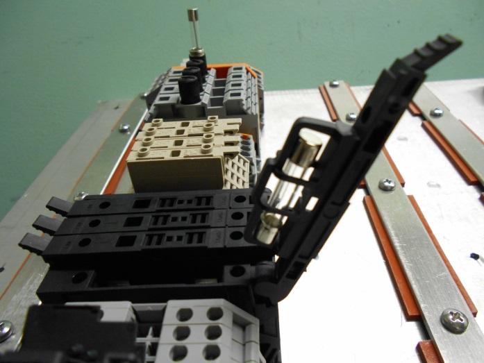
14 Manufacture Demonstrator Pre cable installation (cont.) 14


15 Manufacture Demonstrator Post cable installation Test Plate #1 Test Plate #2 15


16 Manufacture Demonstrator Post cable installation (cont.) 16
17 Test Demonstrator Electrical and physical characteristic testing All units passed electrical testing A couple units failed pull test (only resisted 8 lbs force) for the smallest conductor in the range of applicable conductors NSRP ETP Project: Low Voltage Quick Connectors, Vendor and Product Information Evaluation: Final Listing Mechanism Type Worksheet Number Unit Number per Dwg Name Model/PN Product Description Conductor Size Rated Voltage (V) Rated Power Power Current Capacity Density (A) (kw) (kw/cu in) General Inspection Comments Tensile Pull Resistance Pass/Fail Durability Repeatability Any Failure Experienced Dielectric Test Pass/Fail Insulation Voltage Drop Thermal Shock Test Vibration Resistance Test Cycling Pass/Fail Test Pass/Fail (ohms) Pass/Fail Pass/Fail Ease of Use (conductor and unit installation) Ease of Inspection Holding Mechanism Durability Overall Applicability Score Rating Remarks 1 2 MIL qualified terminal block Term Block A-A-59125/24 for lugged terminations, for Baseline 16TB-12 Baseline Pass 10 G Pass Satisfactory Satisfactory M 314-BOX Insulation Displacement, 3- wire splicing connector, flame retardant and moisture resistant Pass/Pass / Pass/Pass Satisfactory Satisfactory 3 11 Wago splicing connector Push wire 4-conductor Pass/Pass / Pass/Pass Satisfactory Satisfactory 4 13 Wago Splicing Connector Pass/Pass / Pass/Pass Satisfactory Satisfactory 5 14 Ideal Model 39/ J 3 Port Push-In Connector Pass / Pass/Pass Satisfactory Satisfactory 6 35 Tyco 925 Flat bottom Miniature Terminal Block, Tubular Screw Clamp Pass 6 G Pass Satisfactory Satisfactory 7 6 Tyco Position Terminal Block Pass 4 G Pass Satisfactory Satisfactory 8 15 Phoenix Contact PT 1,5/S DIN Raol mounted, quick connecting terminal block; spring Pass 4 G Satisfactory Satisfactory 9 16 Phoenix Contact PT 2,5 DIN Rail mounted, quick connecting terminal block; spring cage Pass 4 G Satisfactory Satisfactory Cooper Bussman Gangable Connector Block 2/0-8 PDBFS 220 Distribution Block (1 in to 4 Source, 4-14 out) Load Pass 5 G Pass Satisfactory Satisfactory Tyco N/A Bus Bar Assembled with 2 3/8" power Posts, connectors, cables supplied Pass/Pass 3 G Pass Satisfactory Satisfactory 17


18 Testing References 18
19 Testing Requirements Order of Test Test Standard Called Out By Section or Method 3 Voltage Drop Mil-T-16366F Dielectric Withstand Mil-Std-202G Shock Mil-Std-202G Mil-C Mil-Std-901D 6 Vibration Mil-Std-167-1A Mil-C Demonstrator Unit Testing 7 Temperature Cycling Mil-Std-202G Mil-C Cond D Reference Test Values Remarks 6-25mV at rated voltage -2x rated voltage V for 60 sec -leakage current less than 0.1% rated load - continuity maintained better than 10% of contact resistance value (drop no less than m in, 0-34 Hz in approx. 6 hrs to -5 C 15 min 25 to -5 C 5 min 350 to 0 C 15 min 25 to -5 C 5 min 1, 8 Contact Retention/Pull Resistance Mil-C , lb/min 2 Insulation Resistance Mil-C M Contact Resistance (TDR) Mil-C A 2.67 m - used for 4-30 A units operating at rated current - raise voltage 500 V/sec - Mil-C uses 1500 V for 60 sec - inspect for damage to mounts, contacts, springs, etc. - inspect for damage to mounts, contacts, springs, etc. - inspect for damage, maybe conduct pull test is for mated connectors (40 lbs) This will be done during shock and vib testing, instrumenting the demonstrator 19
20 Testing Results Worksheet Number Unit Number per Dwg Tensile Pull Resistance Pass/Fail 1 Insulation Resistance (ohms) 2 Voltage Drop Test Pass/Fail 3 Shock Test Pass/Fail Vibration Test Pass/Fail Thermal Cycling Pass/Fail Post-Test Contact/Pull Resistance Test Ease of Use (conductor and unit installation) Holding Mechanism Durability 1 2 Pass 10 G Pass Pass Pass Pass Pass Satisfactory Satisfactory 2 27 Pass/Pass / Pass/Pass Pass 4 Pass Pass Pass Satisfactory Satisfactory 3 11 Pass/Pass / Pass/Pass Pass Pass Pass Pass Satisfactory Satisfactory 4 13 Pass/Pass / Pass/Pass Pass 4 Pass Pass Pass Satisfactory Satisfactory 5 14 Pass / Pass/Pass Pass 4 Pass Pass Fail Satisfactory Satisfactory 6 35 Pass 6 G Pass Fail 7 Pass Pass Pass Satisfactory Satisfactory 7 6 Pass 4 G Pass Pass Pass Pass Pass Satisfactory Satisfactory 8 15 Pass 4 G Pass Fail 5 Pass Pass Pass Satisfactory Satisfactory 9 16 Pass 5 G Pass Fail 5 Pass Pass Pass Satisfactory Satisfactory Pass 3 G Pass Pass Pass Pass Pass Satisfactory Satisfactory Pass/Pass 4 G Pass Pass Pass Pass Pass Satisfactory Satisfactory 12 9 Pass/Pass 5 G Pass Pass Pass Pass Pass Satisfactory Satisfactory Pass/Pass 10 G Pass Fail 5 Pass Pass Pass Satisfactory Satisfactory Pass/Pass 2.6 G Pass Fail 5 Pass Pass Pass Satisfactory Satisfactory Pass 2 G Pass Fail 5,6 Pass Pass Pass Satisfactory Satisfactory Pass 5 G Pass Fail 5 Pass Pass Pass Satisfactory Satisfactory Pass 2.4 G Pass Fail 5 Pass Pass Pass Satisfactory Satisfactory Pass 6 G Pass Fail 6 Pass Pass Pass Satisfactory Satisfactory Pass 4 G Pass Pass Pass Pass Pass Satisfactory Satisfactory Pass 10 G Pass Pass Pass Pass Pass Satisfactory Satisfactory Fail 3 G Pass Fail 5 Pass Pass Pass Satisfactory Unsatisfactory Pass 3 G Pass Fail 5 Pass Pass Pass Satisfactory Satisfactory Pass 5 G Pass Fail 5 Pass Pass Pass Satisfactory Satisfactory Pass 7 G Pass Pass Pass Pass Pass Satisfactory Satisfactory Fail 7 G Pass Pass Pass Pass Pass Satisfactory Unsatisfactory Pass 4.5 G Pass Fail 7 Pass Pass Pass Satisfactory Satisfactory Pass 3 G Pass Pass Pass Pass Pass Satisfactory Satisfactory Notes: 1 For those cells showing Pass/Pass, 2 conductors for the connector were tested 2 For those cells showing Pass/Pass, voltage drop was measured across connector terminated port and unterminated port, for each conductor 4 No connector test failure or damage. Fastening zip tie broke while testing. 5 Disconnected from DIN rail 6 Chatter present 7 Connector Damage NSRP ETP Project: Low Voltage Quick Connectors, Testing Results 3 For those cells showing /, measurement was made from conductor to ground, for each conductor; for the other units, worst case was across 20

21 Performance Testing Shock Testing 21

22 Performance Testing Vibration Testing 22

23 Performance Testing Thermal Cycle Testing 23


24 Types of Failures End Plates came off Connectors separated from the DIN rail interface Before Testing After Testing Before Testing After Testing Fuse Holders opened Fuses did not fail, however 24
 Foot mounting interface broke Inter unit interfaces broke, causing")

25 Types of Failures (cont.) Foot mounting interface broke Inter unit interfaces broke, causing unit separations Before Testing After Testing Before Testing After Testing Zip Ties broke (temporary constraints not part of test article design) Conductors came loose from the connector 25
26 Cost Benefit Assessment Per unit calculator was used to apply to estimated ship quantities Numbers represent nominal values Hourly rates are arbitrary for demonstration purposes Per unit savings are small Methods and values are conservative in nature Cost Differences in Traditional Connectors and Quick Connectors Item Description Base Mounting Device Mounting Wire Preparation Wire Installation Torquing Device Labor (min) Materials ($) Totals Difference from Traditional Methods Associated Hardware Base Mount Labor (hrs) 1 DIN rail 35 Mounted Quick Connector $1.00 $0.20 $ $1 (0.16) ($1) ($17) 22.7% 2 Foot Mounted Quick Connector $3.00 $0.20 $ $3 (0.13) $1 ($12) 43.5% 3 Currently used Terminal Block $2.08 $ $2 4 In-Line Splice Connetcor $0.40 $0.50 $ $1 (0.24) ($2) ($26) 12.3% 5 Lugged Splice Termination $3.00 $ $3 Notes: 1. The above information is an average of several inputs 2. The above information represents a per unit basis 3. DIN rail mounting estimates is for a strip 24" long, able to hold 40 quick connectors (and end hardware and spacers): takes 30 min. to install 40 units, or 30 sec. pu 4. Wire installation is for input and output sides of respective units 5. Existing terminal strip is divided by the number of terminal pairs (12) 6. Costs are averages across the cross section of units investigated (there is considerable difference, but value can be adjusted easily) 7. Associated hardware includes mounting screws, endplates and spacers (where applicable) 8. Differences is the quick connector method minus the traditional method 9. A positive ROI indicates a savings 10. Spreadsheet designer entry 11. Labor Hourly cost $: 100 Materials ($) Labor (hrs) Materials ($) Total ($) Simple ROI 26
27 Cost Benefit Assessment (cont.) Using estimated equipment quantities and per unit values: Savings are calculated for switching all to new quick connectors Savings are calculated for switching % of available opportunities to QC (not part of purchased equipment) Modest savings over multiple programs reported Opportunity to Switch to Quick Connectors: From Terminal Blocks and Lugged Splice Connectors to Quick Connectors DIN rail 35 Mounted Quick Connector Foot Mounted Quick Connector Currently used Terminal Block In-Line Splice Connetcor Lugged Splice Termination Total Program Average 96,188 32,063 4, ,300 Opportunity Costs to Switch to Quick Connectors from Terminal Blocks and Lugged Splice Connectors: Labor Savings (mhrs) DIN rail 35 Mounted Quick Connector Foot Mounted Quick Connector Currently used Terminal Block In-Line Splice Connetcor Lugged Splice Termination Total Program Average ($1,737) $265 ($394) ($1,865) Opportunity Costs to Switch to Quick Connectors from Terminal Blocks and Lugged Splice Connectors: Hardware Savings ($) DIN rail 35 Mounted Quick Connector Foot Mounted Quick Connector Currently used Terminal Block In-Line Splice Connetcor Lugged Splice Termination Total Program Average ($100,119) $29,391 ($9,315) ($80,044) Opportunity Costs to Switch to Quick Connectors from Terminal Blocks and Lugged Splice Connectors: Total ($) DIN rail 35 Mounted Quick Connector Foot Mounted Quick Connector Currently used Terminal Block In-Line Splice Connetcor Lugged Splice Termination Total Program Average ($101,856) $29,656 ($9,709) ($81,908) Note: Negative values indicate a savings 27
28 Cost Benefit Assessment (cont.) Using estimated quantities to replace that are not purchased with equipment Small savings shown These estimates do not include NRE to change to new design Numbers are conservative A lot are purchased with equipment Opportunity to Switch to Quick Connectors: From Terminal Blocks and Lugged Splice Connectors to Quick Connectors DIN rail 35 Mounted Quick Connector Foot Mounted Quick Connector Currently used Terminal Block In-Line Splice Connetcor Lugged Splice Termination Average 3, ,741 Opportunity Costs to Switch to Quick Connectors from Terminal Blocks and Lugged Splice Connectors: Labor Savings (mhrs) DIN rail 35 Mounted Quick Connector Foot Mounted Quick Connector Currently used Terminal Block In-Line Splice Connetcor Lugged Splice Termination Average (489) (71) (108) (595) Opportunity Costs to Switch to Quick Connectors from Terminal Blocks and Lugged Splice Connectors: Hardware Savings ($) DIN rail 35 Mounted Quick Connector Foot Mounted Quick Connector Currently used Terminal Block In-Line Splice Connetcor Lugged Splice Termination Average (3,184) 487 (1,040) (3,043) Opportunity Costs to Switch to Quick Connectors from Terminal Blocks and Lugged Splice Connectors: Total ($) DIN rail 35 Mounted Quick Connector Foot Mounted Quick Connector Currently used Terminal Block In-Line Splice Connetcor Lugged Splice Termination Average (3,672) 417 (1,148) (3,638) Note: Negative values indicate a savings Total Total Total Total 28
29 Cost Benefit Assessment (cont.) Qualified Benefits include: Troubleshooting, testing and commissioning Flexible configuration and minimal impact to adjacent circuits Reduced installation steps Fewer parts to manage COTS (Commercial Off the Shelf) equipment Qualified benefits may be more important than quantified benefits in some applications User should determine where relative benefits are generated and costs assessed 29
30 Recommendations Future Estimation Work Users should use the tools for their programs and refine as necessary; validation is good practice, but not necessary Universal Requirements Consider requirements that can be invoked on several types of marine programs Drive program specific costs out of multiple programs Qualification Program Vendors to consider ESS qualification Use most stringent requirements, as applicable Product Resilience Vendors to assess and maintain or improve product resilience for targeted markets 30
31 Implementation Identify opportunities Identify hardware and methodology availability Determine qualification status Determine qualification scope of work Estimate costs and schedule associated with qualification Determine overall cost of change Determine point of technology insertion 31
32 Project Summary and Conclusions Project investigated a good cross section of quick connector products to consider All products, for the most part, performed well Some products require re-design to meet the types of requirements used in the project Other products will likely meet stringent requirements as they are currently designed Recommend further cost benefit analysis (which would be part of user implementation plans) Vendors are encouraged to move into qualification plans for their products 32
33 Questions?? Thank you for your support and participation 33
Electric Technologies Panel Meeting Philadelphia, PA Low Voltage Quick Connector Evaluation Status Update
 Electric Technologies Panel Meeting Philadelphia, PA Low Voltage Quick Connector Evaluation Status Update Presented by: Gregory D. Stevens General Dynamics, Bath Iron Works April, 3 rd, 2014 Approved for
PRODUCT SPECIFICATION
 of 3 C Section : For the 200222, 2002323, 2002444, 20025, 200252, 200252, 20026, 200262, 200262, 20028, 200283, 200284, 2002822, 2002824, 200283, 2002832, 2002833, 2002834 and 2002835 series parts..0 GENERAL
SPECIFICATION AND PERFORMANCE TABLE OF CONTENT. 1. Scope Reference Documents Material and Components... 2
 TABLE OF CONTENT 1. Scope... 2 2. Reference Documents.. 2 3. Material and Components...... 2 4. Design and Construction..... 2 5. Rating.. 2 6. Performance and Test Descriptions. 2 7. Test Requirements
Aug07 Rev A All Paragraphs Revised
 Qualification Test Report Universal MATE-N-LOK* Connector 110-213 28Aug07 Rev A All Paragraphs Revised 1. INTRODUCTION 1.1. Purpose 1.2. Scope Testing was performed on Universal MATE-N-LOK* connectors
QUALIFICATION TEST SUMMARY REPORT ESR Qualification Type Testing of Amphenol Corporation s 2M801 Series Connector
 Page 1 of 13 QUALIFICATION TEST SUMMARY REPORT ESR-9389 Qualification Type Testing of Amphenol Corporation s Connector PREPARED BY: Patrick Cole Design Engineer AMPHENOL CORPORATION Aerospace Operation
PRODUCT SPECIFICATION
 1.0mm Pitch ZIF FPC Page 1 Top Entry Side Entry 1.0mm Pitch ZIF FPC Page 2 1.0 SCOPE. This specification covers performance, tests and quality requirements for 1.0mm Pitch ZIF FPC Connector 2.0 APPLICABLE
Series 80 Mighty Mouse Technical Reference Complete Product Specification
 Summary Performance Specifications Current Rating (Maximum): Size #23 Contact: 5 A., Size #20 contact: 7.5 A., Size #16 contact: 13 A., Size #12 contact: 23 A. Test Voltage (Dielectric Withstanding Voltage)
Apr11 Rev A
 Product Specification SMA In-Series Adapters 04Apr11 Rev A 1. SCOPE 1.1. Content This specification covers performance, tests and quality requirements for the TE Connectivity (TE) SMA In-Series Adapters.
Jun06 Rev D
 Product Specification High Speed Serial Data 2 Connector 108-1965 27Jun06 Rev D 1. SCOPE 1.1. Content This specification covers performance, tests and quality requirements for the Tyco Electronics High
PRODUCT SPECIFICATION
 PROUCT SPECIFICATION TABLE OF CONTENTS 1.0 SCOPE 2.0 PROUCT ESCRIPTION 3.0 APPLICABLE OCUMENTS AN SPECIFICATIONS 4.0 RATINGS 5.0 PERFORMANCE 5.1 ELECTRICAL PERFORMANCE 5.2 MECHANICAL PERFORMANCE 5.3 ENVIRONMENTAL
THREADED & BAYONET CONNECTORS FOR DEMANDING ENVIRONMENTS
 MILITARY AND COMMERCIAL AVIATION MIL - DTL - 83723 SERIES III THREADED & BAYONET CONNECTORS FOR DEMANDING ENVIRONMENTS CONNECTORS FOR DEMANDING ENVIRONMENTS THREADED AND BAYONET MILITARY AND COMMERCIAL
HIGH SPEED MEZZANINE PRODUCT SPECIFICATION
 OARD TO OARD CONNECTOR 75005 Receptacle Assembly 75003 Plug Assembly Table of Contents 1.0 Scope 2.0 Product Description 3.0 Applicable Documents and Specifications 4.0 Ratings 5.0 Performance 5.1 Qualification
May2015 Rev A
 Product Specification 108-60104 15May2015 Rev A ANGLED ENTRY JACK FOR CATEGORY 6 APPLICATIONS 1. SCOPE 1.1. Content This specification covers performance, tests and quality requirements for the TE Connectivity
Product Specification Rev A
 Product Specification 108-6116 1. Scope :.5 Signal DBL Lock Connector 18P 1.1 Contents This specification covers the requirements for product performance, test methods and quality assurance provisions
Test Group Description. Total Number. Figure 1. Unless otherwise stated, the following environmental conditions prevailed during testing:
 Qualification Test Report 26 November 12 Rev A1 SL Series Jacks, Category 6 1. INTRODUCTION 1.1. Purpose 1.2. Scope Testing was performed on AMP NETCONNECT* SL Series Category 6 Jacks to determine their
Fuse & Switch. BUCHANAN Terminal Blocks. Product Facts High Density Blocks. Fuse Blocks. Switch Blocks. Common Features of 300 & 0300 Series
 Fuse & Switch Product Facts High Density n Fuse and Switch rated 15A and 300V. n High Density 0.36" [9.14] centerline spacing saves panel space; at least 33 circuits per foot. Fuse n Provide in-line circuit
- (90 - f (GHz)) db (.05 SQT(f(GHz))) db
) db (.05 SQT(f(GHz))) db") TNC Specifications to MIL-C-39012 The specifications below are general specifications for all TNC connectors. Specific Data for VSWR, Insertion Loss, R.F. leakage, etc., are available from the factory
TNC Specifications to MIL-C-39012 The specifications below are general specifications for all TNC connectors. Specific Data for VSWR, Insertion Loss, R.F. leakage, etc., are available from the factory
PRODUCT SPECIFICATION
 288 Ckt Vertical Press Fit DDR4 DIMM 2.4mm Seating Plane 1.0 SCOPE This Product Specification covers the 0.85 mm centerline gold plated DDR4 DIMM edge card connector for 1.40 +/- 0.10 thick memory modules.
Jun 20,2014 Rev A
 Product Specification 108-115067 Jun 20,2014 Rev A DDR4 DIMM Through-hole Memory Socket 1. SCOPE 1.1. Content This specification covers performance, tests and quality requirements for the TE Connectivity
GETWELL TECH.(H.K.) LTD.
 LTD.") GETWELL TECH.(H.K.) LTD. 2.5 Pitch 4 Pin Battery Connector Product Specification PART No: DC-0010S00-067-102 Rev.: A Page:1/ 5 Approved/Date Checked/Date Written/Date 1.0 Scope : This specification covers
GETWELL TECH.(H.K.) LTD. 2.5 Pitch 4 Pin Battery Connector Product Specification PART No: DC-0010S00-067-102 Rev.: A Page:1/ 5 Approved/Date Checked/Date Written/Date 1.0 Scope : This specification covers
SERIES MHV (H4) HIGH VOLTAGE CONNECTORS
 HIGH VOLTAGE CONNECTORS") SERIES MHV (H4) HIGH VOLTAGE CONNECTORS DESCRIPTION CONTENTS PAGE HUBER+SUHNER MHV connectors are coaxial miniature high voltage (MHV = Miniature High Voltage) connectors with 5 kv rms test voltage (mated
SERIES MHV (H4) HIGH VOLTAGE CONNECTORS DESCRIPTION CONTENTS PAGE HUBER+SUHNER MHV connectors are coaxial miniature high voltage (MHV = Miniature High Voltage) connectors with 5 kv rms test voltage (mated
Amphenol 348 Series High Density Connectors
 348 Series High Density Connectors 12-093-6 348 Series I, II Table of Contents 348 Series Page No. High Density Connectors........................................................................ 1 Specifications.................................................................................
SPECIFICATION 宏致電子股份有限公司 桃園縣中壢市東園路 13 號. No.13, Dongyuan Rd., Jhongli City, Taoyuan County 320, Taiwan (R.O.C.)
") SPECIFICATION 宏致電子股份有限公司 桃園縣中壢市東園路 13 號 No.13, Dongyuan Rd., Jhongli City, Taoyuan County 320, Taiwan (R.O.C.) TEL: +886-3-463-2808 FAX: +886-3-463-1800 SPEC. NO.: PS - 87151-XXX9 REVISION: D PRODUCT NAME:
SPECIFICATION 宏致電子股份有限公司 桃園縣中壢市東園路 13 號 No.13, Dongyuan Rd., Jhongli City, Taoyuan County 320, Taiwan (R.O.C.) TEL: +886-3-463-2808 FAX: +886-3-463-1800 SPEC. NO.: PS - 87151-XXX9 REVISION: D PRODUCT NAME:
MINIATURE MIL-DTL TYPE AUDIO FREQUENCY CONNECTORS
 SERIES 151 MINIATURE MIL-DTL-55116 TYPE AUDIO FREQUENCY CONNECTORS FEBRUARY 2012 SERIES 151 MINIATURE MIL-DTL-55116 TYPE AUDIO FREQUENCY CONNECTORS HIGH RELIABILITY PERFORMANCE FOR MISSION-CRITICAL COMMUNICATION
3M Connector System 0.050" x 0.100" Pitch. 3M Tripolarized Wiremount Socket - Series 820 3M 4-Wall, Tripolarized Header - Series 810
 1 of 9 3M Connector System 0.050" x 0.100" Pitch 3M Tripolarized Wiremount Socket - Series 820 3M 4-Wall, Tripolarized Header - Series 810 Product Specification 78-5110-0074-0 Released: 10-1-10 2 of 9
SEP 2016 Rev D2
 Product Specification 108-2112 28 SEP 2016 Rev D2 VAL-U-LOK* Connectors 1. SCOPE 1.1. Content This specification covers performance, tests and quality requirements for VAL-U-LOK* Connectors. 1.2. Qualification
MEZALOK* Stacking Connector System
 Product Specification 108-2411 25 FEB 16 Rev D MEZALOK* Stacking Connector System 1. SCOPE 1.1. Content This specification covers performance, tests and quality requirements for the MEZALOK* Stacking Connector
PRODUCT SPECIFICATION
 MultiCat TM In-line Power Connector System WIRE-TO-WIRE AND WIRE-TO-BOARD MALE CRIMP CONTACT (201845-00X0) FEMALE CRIMP CONTACT (201846-00X0) PLUG HOUSING (201840-00XX) RECEPTACLE HOUSING (201841-00XX)
Product Specification QSL RF Connectors
 Product Specification QSL RF Connectors 108-2324 04Feb09 Rev A 1. SCOPE 1.1. Content This specification covers performance, tests and quality requirements for the Tyco Electronics QSL RF Connectors which
25kV 200A Loadbreak Bushing Insert and Elbow Design Test Report. Report Number:
 25kV 200A Loadbreak Bushing Insert and Elbow Design Test Report Report Number: Date: RN-R7604 9/16/2013 Table of Contents I. OBJECTIVE... 2 II. SUMMARY... 2 III. CONCLUSION... 2 IV. CABLE DATA... 2 V.
Wedge in Plugs Stock No
 Amphenol Connectors Description Plugs Stock No. Receptacles Stock No. 2-way 38170 38171 3-way 38172 38173 4-way 38174 38175 6-way 38176 38177 8-way 38178 38179 12-way 38180 38181 Wedge in Plugs Stock No.
QUALIFICATION TEST REPORT Series 80 Mighty Mouse Connectors
 Sheet 1 of 22 1 INTRODUCTION 1.1 Purpose Testing was performed on Glenair Series 80 connectors to determine conformance to the requirements of Product Specification 809-009 and MIL-DTL-38999. 1.2 Scope
SMB Amphenol. 50 ohm Coaxial Connectors Specifications 36 Plugs 37 Jacks 38 Bulkhead Receptacles PCB Receptacles 41-43
 Description The name derives from SubMiniature B (the second subminiature design). The was developed in the 1960 s. is a smaller version of the SMA with snap-on coupling. Amphenol s connectors conform
PRODUCT SPECIFICATION
 MICRO-FIT BMI FLOATING CONNECTOR SYSTEM 1.0 SCOPE This Product Specification covers the 3.00 mm (.118 inch) centerline (pitch) connector system terminated with 20 to 30 AWG wire using crimp technology
QSFP Copper Module Direct Attach Cable Assembly &Cage
 Qualification Test Report 501-60067 12Mar. 2012 Rev. 1 QSFP Copper Module Direct Attach Cable Assembly& Qualification Test Report QSFP Copper Module Direct Attach Cable Assembly & Tyco Electronics. (Shanghai)
Contents. Glossary Common terms and definitions
 Contents Performance Specifications General technical specifications of AMPSEAL, AMPSEAL 16, Circular DIN, DEUTSCH, HDSCS, LEAVYSEAL, and Superseal 1.0 products... 2 Resources IP rating and wire gauge
AMPLIMITE.050 Series Cable Assemblies, Series III
 Cable Assemblies, Series III To meet Standard Applications the following 106 ohm, black jacketed cable assemblies are available. For AMPLIMITE Series cable assemblies that meet other impedance requirements
Amphenol 67 and 165 Series Miniaturized Standard Connectors
 Amphenol 67 and 165 Series Miniaturized Standard Connectors 12-023-6 Amphenol Table of Contents Page No. Amphenol 67 Series Minni E General Information, Design Characteristics, Customer Options.........................
Connection Systems. Bulls-Eye Subminiature Circular Connectors
 Connection Systems Bulls-Eye Subminiature Circular Connectors Connection Systems Bulls-Eye Subminiature Circular Connectors Hit the target every time with our high density connectors that provide high
DTP Series : Contacts (Open Barrel) Type Barrel Type GA Size
 Type Barrel Type GA Size") Deutsch Connectors DTP Series Deutsch s DTP Series connectors are the solution for your power application requirements. Building on both the DT and DTM design strengths, the DTP connector line was developed
Deutsch Connectors DTP Series Deutsch s DTP Series connectors are the solution for your power application requirements. Building on both the DT and DTM design strengths, the DTP connector line was developed
AUG 16 Rev C2
 Product Specification 23 AUG 16 Rev C2 025 Series Connector 1Row 1. SCOPE 1.1 Contents This specification covers the requirements for product performance, test methods and quality assurance provisions
Serial Attached SCSI (SAS) Connector
 Connector") Product 108-51053 Specification DR: Stanley Huang 24 Oct 2013 Rev G APVD: Vincent Peng Serial Attached SCSI (SAS) Connector 1.0 SCOPE This specification covers the requirements for product performance,
Product 108-51053 Specification DR: Stanley Huang 24 Oct 2013 Rev G APVD: Vincent Peng Serial Attached SCSI (SAS) Connector 1.0 SCOPE This specification covers the requirements for product performance,
Features and Application
 ML-DTL- Features and Application MS2426*/AE66* Features and Application ML-DTL- family offers connectors with bayonet coupling as well as threaded coupling. These connectors are intermateable with correspondingly
PERFORMANCE SPECIFICATION SHEET
 INCH-POUND MIL-PRF-83536/15A 12 July 2004 SUPERSEDING MIL-PRF-83536/15 27 March 1992 PERFORMANCE SPECIFICATION SHEET RELAYS, ELECTROMAGNETIC, ESTABLISHED RELIABILITY, 4PDT, LOW LEVEL TO 10 AMPERES, PERMANENT
How to Order CONTACT TYPE FLANGE TYPE MOUNTING CONTACT TERMINATION
 hermetically sealed connectors are designed to meet environmental conditions of extreme pressure differential. These connectors are part of the ITT Cannon D Subminiature series and are qualified to MIL-C-24308
3M Three-Wall and Four-Wall Headers. Series 3XXX
 1 of 7 M Three-Wall and Four-Wall Headers Series XXX Product 78-10-0008-0 Released: 0-0-11 of 7 Table of Contents Section Page 1. Scope........ M Customer Documents....... Performance and Test Descriptions...
35-kV Apparatus Bushings B Series (bolt-in) for Elbow to Air-Insulated Service 200 Amp, 600 Amp, 900 Amp and 1250 Amp
 for Elbow to Air-Insulated Service 200 Amp, 600 Amp, 900 Amp and 1250 Amp") Page 1 2018 Grounded Metal Equipment Plate Equipment Connection Bus Bar or Other Component 35 kv Separable Insulated Connector (elbow) Grounded Metal Equipment Plate Equipment Connection Bus Bar or Other
Page 1 2018 Grounded Metal Equipment Plate Equipment Connection Bus Bar or Other Component 35 kv Separable Insulated Connector (elbow) Grounded Metal Equipment Plate Equipment Connection Bus Bar or Other
Series 80 Mighty Mouse Technical Reference Complete Product Specification
 80 Mighty Mouse Technical Reference Reference SRIPTION RQUIRMNT PROUR TRI ontact resistance S S39029 Table V Max Wire Test Voltage Size urrent rop 12 23 42 14 17 40 16 13 49 20 7.5 55 22 5 73 24 3 45 26
PRODUCT SPECIFICATION
 1. SCOPE This specification covers the T-FLASH MEMORYCARD SOCKET series. 2. PRODUCT NAME AND PART NUMBER Product Name Part Number Assembly 49225-811 Embossed Package 49225-811 3. RATINGS Item Standard
SMB Connectors Specifications Flexible Cable Bulkhead PCB Mount... 66
 Section Index Connectors Specifications... 62 Flexible Cable... 64 Bulkhead... 65 PCB Mount... 66 Other Information Assembly Instructions... 176 Cable Assembly... 166 Cable Information... 168 Numerical
Bodies Brass Nickel or Gold Gold Female: Beryllium copper Insulator Teflon N/A Crimp ferrule Annealed copper Nickel or Gold
 Materials Connector part Material Finish Bodies Brass Nickel or Gold Center Contact Male: Brass Gold Female: Beryllium copper Insulator Teflon N/A Crimp ferrule Annealed copper Nickel or Gold Electrical
DT04 08P + W8P
 Deutsch Connector Assortment Flip Kit *763354 This assortment contains 574 pieces/sets of widely used Deutsch Connectors. Flip Kits are handy both in the shop and the service vehicle. They are portable,
CMC Hybrid Connectors Standard and Power Versions
 CMC hybrid connectors and mating headers provide sealed, high-density, modular and cost-effective wire-to-board and wire-to-wire connection systems for heavy-duty powertrain and body-electronics applications
PRODUCT SPECIFICATION
 ML-XT COMMERCIAL VEHICLE CONNECTOR SERIES 1.0 SCOPE This Product Specification relates to the ML-XT Commercial Vehicle, (CV), Power and/or Signal wire-to-wire connector system. This system consists of
Product Specification AMP Mini CT DC Drawer Connector, 1.5 mm Pitch Lead Free Version
 Product Specification 108-60026 MP Mini CT DC Drawer Connector, 1.5 mm Pitch Lead Free Version 1. 1.1 Scope: Contents: This specification covers the requirements for product performance, test methods and
25-kV Apparatus Bushings B Series (bolt-in) for Elbow to Air-Insulated Service 200 Amp, 600 Amp, 900 Amp and 1250 Amp
 for Elbow to Air-Insulated Service 200 Amp, 600 Amp, 900 Amp and 1250 Amp") Page 1 2018 Grounded Metal Equipment Plate Equipment Connection Bus Bar or Other Component 15 kv or 25 kv Separable Insulated Connector (elbow) Equipment Connection Power Cable Power Cable ELRIM Cycloaliphatic
Page 1 2018 Grounded Metal Equipment Plate Equipment Connection Bus Bar or Other Component 15 kv or 25 kv Separable Insulated Connector (elbow) Equipment Connection Power Cable Power Cable ELRIM Cycloaliphatic
Luminus Series Amphenol Pcd
 Luminus Series Amphenol Pcd Amphenol Pcd Pcd is is one one of of the the world s leading suppliers of of interconnect products for for Military, Commercial Aerospace and and Industrial applications. Located
RECTANGULAR CONNECTORS PER ARINC 404 RM-RME SERIES
 Rev. C, March, 2016 RECTANGULAR CONNECTORS PER ARINC 404 RM-RME SERIES Connectors with wide range of shell configurations/modifications, contact arrangements and contacts to meet ARINC 404 Specification
35-kV 200-kV BIL Apparatus Bushings B Series (bolt-in) for Elbow to Air-Insulated Service 200 Amp, 600 Amp, 900 Amp and 1250 Amp
 for Elbow to Air-Insulated Service 200 Amp, 600 Amp, 900 Amp and 1250 Amp") Page 1 2018 Grounded Metal Equipment Plate Equipment Connection 35 kv Separable Insulated Connector (elbow) Bus Bar or Other Component Grounded Metal Equipment Plate Equipment Connection Bus Bar or Other
Page 1 2018 Grounded Metal Equipment Plate Equipment Connection 35 kv Separable Insulated Connector (elbow) Bus Bar or Other Component Grounded Metal Equipment Plate Equipment Connection Bus Bar or Other
Eaton s Cooper Power Systems
 Page: 1 of CERTIFIED TEST REPORT Eaton s Cooper Power Systems 600 Amp - 35 kv Class Deadbreak Bushing With Internal Ground Screen Design Qualification Tests December 17, 2013 Supersedes 10/20 2013 Eaton
Amphenol Australia. ATM Series PRODUCT SHORTFORM. Amphenol Australia Pty Ltd. ATM Series
 EX-STOCK AUSTRALIA ATM Series PRODUCT SHORTFORM Amphenol Australia Pty Ltd ATM Series ATM Series connectors are a high-performance, cost-effective solution specifically designed for smaller AWG applications,
CMC Hybrid Connectors Standard and Power Versions
 CMC hybrid connectors and mating headers provide sealed, high-density, modular and cost-effective wire-to-board and wire-to-wire connection systems for heavy-duty powertrain and body-electronics applications
3M CP2 Press-Fit Headers and Sockets, 2 mm
 1 of 7 3M CP2 Press-Fit Headers and Sockets, 2 mm A-Style CP2 Connectors CP2-SA110-G1-KR Right Angle Socket Connectors mated to CP2-HA110-GA1-KR Header Connectors 78-5102-0083-1 Revised Date: February
Features and Application
 MIL-DTL-38999 Features and Application Series II Features and Application MIL-DTL-38999 Series II connectors feature a bayonet coupling mechanism with lower profile design and rear-removable crimp contact
DT Series Technical Manual
 Deutsch Industrial UK Stanier Road St. Leonards On Sea East Sussex TN 9RF England Ph. (0) 7 Fax (0) 979 industrialuk@deutsch.net Deutsch Industrial Europe Fraunhoferstrasse b Martinsried Germany Ph. +9
AUGUST 28, 2008 TEST REPORT # REV.1.1 MIXED FLOWING GAS TESTING CONNECTOR SERIES SEM H-D-WT TEM H-D-WT SAMTEC, INC.
 AUGUST 28, 2008 TEST REPORT #208383-5 REV.1.1 MIXED FLOWING GAS TESTING CONNECTOR SERIES SEM-125-02-03.0-H-D-WT TEM-125-02-03.0-H-D-WT SAMTEC, INC. APPROVED BY: DOMINIC ARPINO PROGRAM MANAGER CONTECH RESEARCH,
AUGUST 28, 2008 TEST REPORT # REV.1.1 MIXED FLOWING GAS TESTING CONNECTOR SERIES CLP S-D-A FTSH S-DV-A SAMTEC, INC.
 AUGUST 28, 2008 TEST REPORT #208383-3 REV.1.1 MIXED FLOWING GAS TESTING CONNECTOR SERIES CLP-130-02-S-D-A FTSH-130-02-S-DV-A SAMTEC, INC. APPROVED BY: DOMINIC ARPINO PROGRAM MANAGER CONTECH RESEARCH, INC.
Modification Record of Product Specification
 Modification Record of Product Specification No, DSP-14 1303 Product Name SRV Connector Systems Rev. No, Note Reason Place Date Engineer R0 Initial Release DEC 2.19.14 A.M. Page 1/17 PRODUCT SPECIFICATION
Type N connectors DIVIDER PAGE
 Type N connectors DIVIDER PAGE 179 N interface dimensions E D REF. PLANE REF. PLANE C D ØF ØB ØA ØA ØB ØE SEALING GASKET.625-24UNEF-2B G C H MIN. FULL H J F G MIN. FULL "N", MALE, Mil-Std-348A Fig. 304.1.140.110
DEUTSCH HDJ Series Filter Connectors MIL-DTL SERIES I.5
 DEUTSCH HDJ Series connectors are subminiature environment-class connectors with high and medium-density insert arrangements. They are based on MIL-DTL-38999 Series I coupling interface lengths and Series
15 kv and 25 kv Thru-Bushings
 Page 1 2001 ELRIM Cycloaliphatic Epoxy Provides: Nontracking, self-scouring, nonweathering performance Superior dielectric strength, dielectric loss and power factor Choice of shapes allows design innovation
MS-Series. Circuit Breaker
 MS-Series Circuit Breaker Carling Technologies MS-Series Sealed Toggle Circuit Breaker was designed and tested to operate flawlessly in the harshest of environments. Ideally suited for COTS (commercial
nterconnect compatibility new SEALED CONNECTORS harsh environment dual seals for harsh environments ergonomic locking tab for easier mating
 new harsh environment SEALED CONNECTORS nterconnect dual seals for harsh environments ergonomic locking tab for easier mating compatibility AT Series plug wedges ensure a proper seal placement and contact
35-kV Thru-Bushings F Series (bolt-in) for Air-Insulated to Air-Insulated Service 200 Amp, 600 Amp, 900 Amp and 1250 Amp
 for Air-Insulated to Air-Insulated Service 200 Amp, 600 Amp, 900 Amp and 1250 Amp") Page 1 2018 Equipment Connection Bus Bar, or Grounded Metal Equipment Plate F Series Mounting Holes ELRIM Cycloaliphatic Epoxy Provides: Nontracking, self-scouring, nonweathering performance Superior dielectric
Page 1 2018 Equipment Connection Bus Bar, or Grounded Metal Equipment Plate F Series Mounting Holes ELRIM Cycloaliphatic Epoxy Provides: Nontracking, self-scouring, nonweathering performance Superior dielectric
25 kv Apparatus Bushings
 Page 1 2001 ELRIM Cycloaliphatic Epoxy Provides: Nontracking, self-scouring, nonweathering performance Superior dielectric strength, dielectric loss and power factor Choice of shapes allows design innovation
DETAIL SPECIFICATION SHEET
 METRIC MIL-DTL-38999/36 30 November 2006 DETAIL SPECIFICATION SHEET CONNECTORS, ELECTRICAL, CIRCULAR, THREADED, PLUG, LANYARD RELEASE, FAIL-SAFE, REMOVABLE CRIMP CONTACTS, PINS, SHELL SIZE 25, SERIES III,
Volume-III : Section-I 370 Technical Specifications
 Volume-III : Section-I 370 TECHNICAL SPECIFICATION-PIERCING INSULATOR 5.1 Insulation Piercing Connectors (IPC) 5.1.1 Insulation Piercing Connectors (IPC) are used for making Tee/Tap-off/Service connectors
JUNE 11, 2010 TEST REPORT # S2SD CABLE ASSEMBLY QUALIFICATION TESTING PART: T2SD L D-NDS MATING PART: S2M L-D-LC SAMTEC, INC.
 JUNE 11, 2010 TEST REPORT #210199 S2SD CABLE ASSEMBLY QUALIFICATION TESTING PART: T2SD-30-24-L-03.00-D-NDS MATING PART: S2M-130-02-L-D-LC SAMTEC, INC. APPROVED BY: DOMINIC ARPINO PROJECT ENGINEERING MANAGER
2.92mm connectors DIVIDER PAGE
 connectors DIVIDER PAGE 167 interface dimensions REF. PLANE F SEALING GASKET E NOTE 1 F REF. PLANE E G.312 HEX. ØD ØC ØB ØD ØC ØB ØA A.250-36 UNS-2B H.250-36 UNS-2A.170 FULL MALE, FEMALE, Mil-Std-348A
MIL-DTL Series IV Connectors
 DEPENDABLE Secure breech lock coupling 100% scoop-proof Pin-to-pin mating protection helps prevent failures RUGGED Mated connectors help withstand high-impact shock Rear accessory threads help provide
Table of Contents SMA CONNECTORS
 Table of Contents 45 SMA Connectors 3 MMCX Connectors 50 Ohm Connectors Specifications...46 Quick Connect...49 Semi-Rigid & Flexible Cable...50 PC Mount...56 Bulkhead & Panel Mount...62 Self-Fixture End
Sealed Sensor Connector (SSC) System
 System") Introduction Product Features Robust housing, glass filled PBT for high temperature applications Terminal Position Assurance (TPA) to assure proper position of contact in housing Damage protected internal
Introduction Product Features Robust housing, glass filled PBT for high temperature applications Terminal Position Assurance (TPA) to assure proper position of contact in housing Damage protected internal
Single Pole Circuit Protectors 55. Multi-Pole Circuit Protectors 56. Configurations 58. Operating Characteristics 59.
 Single Pole Circuit Protectors 55 Multi-Pole Circuit Protectors 56 Configurations 58 Operating Characteristics 59 Delay Curves 60 Specifications 61 Decision Tables 62 SINGLE POLE CIRCUIT PROTECTORS The
AP/UP, AP/MIL Series Magnetic Circuit Protectors
 AP/UP, AP/MIL AP/UP, AP/MIL Series Magnetic Circuit Protectors Introduction 68 Single Pole 69 Multi-Pole 70 Configurations 72 Operating Characteristics 73 Delay Curves 74 Specifications 75 Decision Tables
APRIL 19, 2010 TEST REPORT # S2SD CABLE ASSEMBLY QUALIFICATION TESTING PART: S2SD S D-NUS MATING PART: T2M L-D-TH
 APRIL 19, 2010 TEST REPORT #209698 S2SD CABLE ASSEMBLY QUALIFICATION TESTING PART: S2SD-30-24-S-02.75-D-NUS MATING PART: T2M-130-01-L-D-TH SAMTEC, INC. APPROVED BY: ALICE HATHAWAY PROJECT ENGINEER CONTECH
SERIES BMA, SUBMINIATURE BLIND MATE CONNECTORS
 SERIES, SUBMINIATURE BLIND MATE CONNECTORS DESCRIPTION CONTENTS PAGE HUBER+SUHNER blind mate connectors open up special dimensions in microwave applications up to 18 GHz. HUBER+SUHNER offers a range of
RF COAXIAL CONNECTORS, TYPE SMA, 50 OHMS (FEMALE CONTACT) ESCC Detail Specification No. 3402/002
 ESCC Detail Specification No. 3402/002") Page 1 of 106 RF COAXIAL CONNECTORS, TYPE SMA, 50 OHMS (FEMALE CONTACT) ESCC Detail Specification Issue 5 June 2016 Document Custodian: European Space Agency see https://escies.org PAGE 2 LEGAL DISCLAIMER
Page 1 of 106 RF COAXIAL CONNECTORS, TYPE SMA, 50 OHMS (FEMALE CONTACT) ESCC Detail Specification Issue 5 June 2016 Document Custodian: European Space Agency see https://escies.org PAGE 2 LEGAL DISCLAIMER
2mm Pitch Miniature Connector for HDD
 ll non-rohs products have been discontinued, or will be discontinued soon. Please check the products status on the Hirose website RoHS search at www.hirose-connectors.com, or contact your Hirose sales
Arktite Heavy Duty Circuit Breaking Plugs and Receptacles Industrial Heavy Duty Non-Hazardous Areas
 1P Arktite Heavy Duty Circuit Breaking s and s Industrial Heavy Duty Non-Hazardous Areas Application: Arktite circuit breaking plugs and receptacles are used: to supply power to portable electrically operated
DETAIL SPECIFICATION SHEET
 METRIC MIL-DTL-38999/31E 12 March 2014 SUPERSEDING MIL-DTL-38999/31D 19 April 2002 DETAIL SPECIFICATION SHEET CONNECTORS, ELECTRICAL, CIRCULAR, THREADED, PLUG, LANYARD RELEASE, FAIL-SAFE, REMOVABLE CRIMP
Battery Cables. Wire & Cable
 Battery Cables Why Use Larger Cable? Low-voltage power systems with inverters can have very high current through the cables that connect the inverter to the batteries. Large AC loads like microwave ovens,
8.2. Terminal Blocks, Fuse Blocks and Fuse Holders. Contents Description C381 Series Terminal Blocks, Rail Mounted...
 .2 Product TBA and TBD modular terminal blocks are designed to conserve space, while allowing maximum flexibility and ease of installation. Available as one-, two- and three-pole circuits, simple and uniform
 Distributed by: www.jameco.com 1-800-831-4242 The content and copyrights of the attached material are the property of its owner. Connectors Features Snap-on interface facilitates assembly Conforms to CECC
REVISION HISTORY REVISION NUMBER. DATE PAGE CONTENTS New 28-May-2015
 Title 1 11 REVISION HISTORY REVISION NUMBER DATE PAGE CONTENTS New 28-May-2015 2 11 3 11 1.Scope This standard specifies EVFC whose rated voltage is 500V DC and breaking capacity is 10000A (hereinafter
Metal Oxide Varistor Thermally Protected Type. TPV Series FEATURE PART NUMBERING SYSTEM LEAD CONFIGURATION SURGE CURRENT STANDARD WAVEFORM
 FEATURE Operating Temperature: -55 C ~ +85 C Varistor : 200V ~ 1200V Two or Three terminal thermally protected Metal Oxide Varistor. High peak Surge current rating up to 10KA Standard lead form and spacing
DETAIL SPECIFICATION SHEET
 INCH-POUND 30 June 2014 SUPERSEDING MIL-DTL-16377/53C 27 September 2005 DETAIL SPECIFICATION SHEET FIXTURES, LIGHTING; INCANDESCENT AND LIGHT EMITTING DIODE (LED), DETAIL LIGHTING, LANTERN, HAND, PORTABLE
Mipco Connections for Refrigerated Containers. No One Does It Like Mipco. The Mipco. Advantage. Reliability. Safety. Easy Installation & Service
 No One Does It Like Mipco Mipco Interlocked Reefer Power Outlets are used extensively in port terminals and shipboard applications to provide a safe, watertight electrical connection for refrigerated containers.
DuraSeal Heat-Shrinkable Environmentally Sealed, Nylon Insulated Crimp Terminals and Disconnects
 Sealed, Nylon Insulated Crimp Terminals and Disconnects Product Facts Resistance to moisture and abrasion Strain relief Protection from wire pull-out Easy installation UL and CUL listed R Approvals and
for Quadrax and ELIO 8
 1 - CHARACTERISTICS Mechanical Current ratings, continuous: Endurance: 500 matings Insertion and extraction forces, max: - shell size 1: 120 N (27 Ibs) - shell size 2: 267 N (60 Ibs) - shell size 3: 467
Interface Mating Dimensions
 SMPM Coaxial Connectors SMPM Connectors DC - 65 GHz SV Microwave offers a complete line of SMPM connectors. SMPM connectors, a push-on mating design, provide microwave performance through 65 GHz and offer