User Manual 123electric Battery Management System 123\BMS Revision 1.4 Augusts 2015
|
|
|
- Kristin Norman
- 5 years ago
- Views:
Transcription

1 User Manual 123electric Battery Management System 123\BMS Revision 1.4 Augusts 2015
2 Table of contents Introduction... 3 System structure... 3 Keep the batteries in a perfect condition : ALWAYS!... 5 Specifications... 6 BMS Board mounting... 7 Cell Board LED... 9 TC / Elcon wiring diagram overview Split pack wiring overview Controller connections Boardnet connections Current sensor connections TC/Elcon charger connections Software settings Screen-shots electronic dashboard
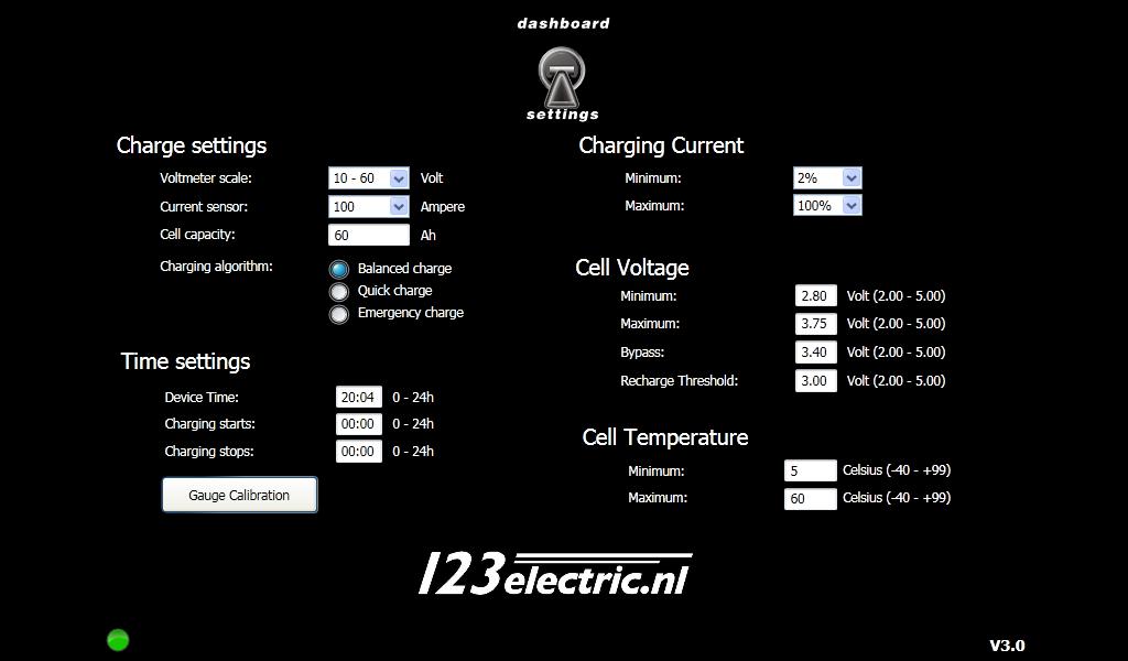
3 Introduction After the introduction of affordable Lithium-Ferro-Phosphate batteries, finally electric cars, boats, and motorcycles have become feasible. However, LiFePO4-batteries can easily be over-charged, or over-discharged. It is therefore vital that these batteries are treated very carefully. For a maximum range, and a long life, intelligent battery management is of utmost importance. The 123electric Battery Management System ( or short : BMS ) is primarily intended for prismatic LiFePO4-cells, but can also be adapted by the end-user for other cells like Li-Ion and LiPo, provided the cell-voltage is in the range of 2V to 5V. System structure The 123electric BMS is designed for battery-packs that have many cells in series, to form a high voltage battery-pack. Each cell is equipped with a small BMS-board, that monitors cell parameters like cell-number, cell-voltage, cell-temperature and bypasscurrent. These boards send this data via a one-wire interface to the BMS-controller. This controller collects all this data, and displays that via a USB-interface on a Windows Computer. A free downloadable electronic dashboard ( ) tells you in the blink of an eye, what the status of the battery-pack is. In the 'settingsmenu' of this program the user can adapt the system to his personal requirements : - Volt meter range ( 5 choices ) - Current meter range ( 3 choices, depending on the current sensor used ) - Cell Capacity ( Ah ) - Charging Algorithm ( balanced -, quick- or emergency- charge ) - Real Time Clock ( 24 h ) - Charging start time - Charging stop time - Minimum Charging Current ( depending on charger used ) - Maximum Charging Current ( depending on charger used ) 3
4 - Minimum Cell Voltage ( error-level ) - Maximum Cell Voltage ( error-level ) - Bypass Voltage ( balancing voltage ) - Recharge Voltage ( charge refresh ) - Minimum Cell Temperature ( error-level ) - Maximum Cell Temperature ( error-level ) - Gauge linearization ( for current- and capacity- gauge ) - External current meter-scale selection The 123\BMS-controller can be connected with most chargers from the TC/Elcon-range, via the three-wire control-connector. ( No CAN option required ) To indicate an error-condition, two relay-outputs are available : one output (Ry2) is active to indicate that the charger is still connected to the mains, and the other output (Ry3) tells you that the communication between the cell-boards is lost and/or that one cell exceeds maximum temperature and/or the cell-voltage is outside the specified range. For those who convert a car into an electric vehicle the 123\BMS-controller supplies an output that mimics the float-resistor in a fuel tank. With this feature one may decide to use the already existing gauge as a remaining capacity ( fuel ) indicator. A second output is available to indicate the actual current. The electronic dashboard offers a simple way to linearise almost any gauge. 4

5 Keep the batteries in a perfect condition : ALWAYS! The drawing below shows that your expensive batteries are in good hands with 123 electric. The 123\BMS-system pre-sets the Coulomb counter to 100% when either all cells get to V-bypass or when one cell reaches V-max. (You can change these voltage settings with the electronic dashboard by yourself ) Note : the Coulomb counter is also set to 100% after a power-down. The left side of the green ( safe ) area, can also be set by yourselves. If you use 90 Ah cells for instance, and you only want to use 60% of the capacity, you can enter 60% of 90 Ah = 54 Ah in the field for Cell-capacity. Conclusion : the upper limit is safe-guarded by entering V-max / V-bypass, and the lower limit by Cell-capacity ( and on top of that, an error-condition is issued when one cell gets lower then Vmin, so you can be pretty sure you are never ruining your cells ) 5
6 Specifications Supply-voltage of BMS-controller 8-30 Volts DC Idle current of the BMS-controller inclusive current sensor < Amp. Number of cells Balancing current 1 Amp. ( regardless of cell-voltage ) Idle-current BMS-board < 100 micro Amp. Current-sensor 100 / 200 or 400 Amp. A/D-resolution 1024 steps ( 10 bit ) Cell-voltage in steps of 0,01 Volt ( 2,00 5,00 V ) Cell-temperature in steps of 1 degree ( -40 to 99 Celsius ) Scan-time per cell 0,015 Seconds Factory-settings Vmin = 2,50 Volt Vmax = 3,75 Volt Vbyp = 3,40 Volt Vchg = 3,00 Volt Tmin = + 0 degrees Celsius Tmax = +60 degrees Celsius 6
 can easily damage the electronic circuits.")
7 BMS Board mounting WARNING : be aware that your battery-pack contains a large amount of energy, which can be potentially lethal. Use isolated spanners, to prevent any short circuits. High inrush currents ( causing sparks and ultra-high electro magnetic levels ) can easily damage the electronic circuits. We therefore strongly recommend to connect all large current connections first and to connect the BMS-boards later. A good way of doing this is indicated on photo number one. Standard M8-bolts are modified with an M4 threaded hole in the top. After thorough cleaning of the cell-poles, the copper strips are bolted-on using a good anti-oxidant joint compound like NOALOX. Don't forget to also attach wires to the first and last cell in the same way, and connect these to the charger and the motor-controller. 7
8 Now, prepare the BMS-boards as shown on photo number two. Use thick solid-copper wire for this, for optimum accuracy. ( the bypass-current has to flow through these wires ) Take your time : the end-result has to look good! Connect all the boards as shown in photo number three. The BMS-board always to be mounted on the 'plus'-pole of the cell. This '+' is also indicated on the board. Remember to use an 'IN'-board for the first cell, and an 'OUT'-board for the last cell. ( see "wiring diagram overview" ) Might you have two battery packs, like one in front and the other in the back of a car, you will have to equip each individual pack with its own 'IN' and 'OUT'-board. ( see "split pack wiring overview" ) For optimum noise-immunity the wiring from- and to- the "IN" and "OUT" boards, will have to be so called "twisted-pair". ( see "wiring diagram overview" and/or "split pack wiring overview" ) It speaks for itself, that if you would plan to use for instance three packs, that you will have to order three "IN"-boards, and three "OUT"-boards. The one-wire interconnect should be soldered as indicated in the diagrams. Use a small soldering-iron, and take your time to do this job VERY carefully. The quality of your work effects reliability greatly. NOTE: Make sure the BMS boards are located in a dry and dust free area, otherwise we advise to use a PCB coating, to be applied after the installation is completed. 8
9 Cell Board LED When the system is installed properly, the Green LED on the cell board will tell you some information. -When the system is in idle mode the LED will flash one time in four seconds. - When the system is active (this means: charger activated or 12 Volt contact voltage on Pin number 9 of the control connector) the LED will flash more often for more accurate information of the cells. - When the LED is lightning continuous the Cell voltage has reached the By-pass voltage. From now on the cell board will dissipate 1 Amp in to heat. WARNING: The black transistor will be hot! If the communication error sign light op in the electronic dashboard there is something wrong with the communication between the cell boards. The controller tries every 8 seconds to send a new message to the boards. You can easily find the problem by visual inspection. The location where the flashing LED s stop working causes the problem. Please check the interconnection, dust, short circuits etc 9

10 TC / Elcon wiring diagram overview 10

11 Split pack wiring overview 11
 6. Ground (for analog controlled TC/Elcon charger) 7. Not Connected 8. Not Connected 9.")
12 Controller connections Charger: 1. Not Connected 2. Not Connected 3. Not Connected 4. Enable (for analog controlled TC/Elcon charger) Volt Input (for analog controlled TC/Elcon charger) 6. Ground (for analog controlled TC/Elcon charger) 7. Not Connected 8. Not Connected 9. Not Connected 10. Not Connected 12
13 BMS: 1. BMS out 2. BMS out 3. BMS in 4. BMS in Current Sensor: 1. Ground 2. Analog in 3. Switched power to sensor 4. Not Connected Control: 1. Ground 2. Not Connected 3. Relay output 3 ( Closed if BMS-comm. is lost or if T>Tmax or if ) 4. Relay output 3 ( V<Vmin or V>Vmax whilst contact is on ) 5. Analog fuel gauge output ( Coulomb-counter ) 6. Relay output 2 ( Closed if Mains connected whilst contact is on ) 7. Relay output 2 8. Analog current gauge output 9. Switched 12/24 Volt power ( contact ) 10. Power supply 12/24 Volt ( permanent connection ) 13

14 Boardnet connections In the above schematic the 123electric current- and fuel- gauges are drawn. Might you want to use your existing fuel gauges instead, you are free to do so. The BMS controller mimics a variable resistor between 0 and 240 Ohms and therefore practically any fuel gauge can be used. With the help of analog gauge calibration in the dashboard-software you should be able to linearize the reading of your gauge. 14

15 Current sensor connections Control Unit: Current sensor: 1. Ground Volt power 2. Analog input 2. NC Volt power 3. Analog output 4. NC 4. Ground 15
16 Notes: Connect everything correctly, prevent making a wrong connection. Two potentiometers can be adjusted by turning slowly to the required accuracy with a small screwdriver. 16
 Pin 5 & cable ( supplied with the charger ) Ground ( Black )")
17 TC/Elcon charger connections Control unit: TC/Elcon charger: Enable( Green ) Pin 4 Standard TC/Elcon connector- 12 Volt( Red ) Pin 5 & cable ( supplied with the charger ) Ground ( Black ) Pin 6 17

18 Software settings Voltmeter scale: In this part of the settings menu you can select one of five different volt meters on the electronic dashboard for the correct reading of your pack voltage : Volt Volt Volt Volt Volt Current sensor: The 123BMS can work in conjunction with one of three different current sensors. Chose the one that you ordered : 100 Ampere 200 Ampere 400 Ampere Note: selecting another current sensor will automatically select another current-scale on the electronic dashboard. Note: changing current-sensor and/or capacity results in the preset to 100% of the Coulomb-counter. 18
19 Cell capacity: The cell capacity can of course be set to the capacity of the cells used. We advise however to take only 70% of the rated capacity, to comply with cell aging and temperature effects. Example: if you have 90 Ah cells, enter 65 Ah in the capacity field. CHARGING ALGORITHM : Balanced charge: When the charging-process begins, the current slowly increases to the maximum charging current selected, until one of the cells reaches the bypass-voltage. At that point the charging-current will ultimately be reduced to the minimum charging current selected. Charging ends when one of the cells reaches the maximum cell voltage OR when all cells reach the bypass-voltage. Note: We advise to use balanced charge at least regularly but certainly when the battery pack is new. When you replace one of the cells in a pack ( or for priming for instance ) balanced charge may come in handy. Quick charge: After the charging-process begins, the current slowly increases to the maximum charging current selected, until one of the cells reaches the maximum-voltage OR all cells reach the bypass-voltage. At that point the charging ends. Emergency charge: In a situation where BMS communication is lost (Cell Voltage much to low or cable rupture) it would become impossible to charge the battery pack. For this situation emergency charge can be selected in the electronic dashboard. Charging will start even without BMS communication. Your supervision is vital here as you can imagine. After a period of 30 minutes the charging process will be stopped anyway for this reason. 19

20 Device time: Here you can enter the time in a 24h fashion. The realtime clock will be kept up-to-date as long as 12 / 24 Volt will be supplied to the unit. Charging starts: Here you can enter the time after which charging is permitted. Charging only will be enabled at the moment that the device time equals the start time. Charging stops: Here you can enter the time after which charging is not permitted. Charging only stops at the moment that the device time equals the stop time. Important: If the start- and stop- time are equal charging will always be enabled. 20

21 Minimum: The final current after balanced charging should approach the 1 Ampere bypass-current of the BMS boards. The minimum can be set from 2% to 17% of the maximum charging current supplied by your charger. Example: Maximum charging current is 30 Ampere. 1 Ampere would be 3.3% Select 4% as minimum charging current. Maximum: The maximum charging current can be set to 20%, 40%, 60%, 80% and 100%. This feature may come in handy when you are in a situation where only reduced current is available. Example: assume that you have only 230 Volt, 6 Ampere available ( 1380 Watt ) and you have a 3000 Watt charger. If you set the maximum current to 40% you will only use 1200 Watt. Take into account that charging time will increase accordingly. 21

22 Minimum: If one of the cells gets below this threshold the L -indicator on the electronic dashboard is switched on, and the error relay ( Ry3 ) will be activated provided the contact is on. ( factory-setting is 2.50 Volt ) Maximum: If one of the cells gets above this threshold the H -indicator on the electronic dashboard is switched on, and the error relay ( Ry3 ) will be activated provided the contact is on. ( factory-setting is 3,75 Volt ) Bypass: This is the voltage where you want all the cells to end up. When you have selected balanced charging you will get to this situation every charging cycle. In quick charge mode however it may take several cycles. ( factory-setting is 3,40 Volt ) Recharge Threshold: Assume you leave your electric vehicle connected to the mains for a long time. Obviously you don t want to start a charging cycle every day but you want to keep your battery pack up to date. So, if one of the cells gets below the recharge threshold a new charging cycle will start. ( factory-setting is 3,00 Volt ) 22

23 Minimum: If one of the cells gets below this threshold the L -indicator on the electronic dashboard is switched on. Both Balanced charge and Quick charge will be suspended as long as one of the cells are below the minimum temperature set. ( some battery chemistries may not be charged below zero degrees Centigrade ) The charging-process will re-start immediately when the cell-temperature is within the safe area selected. ( factory-setting is 0 degrees Celsius ) Maximum: If one of the cells gets above this threshold the H -indicator on the electronic dashboard is switched on, and the error relay ( Ry3 ) will be activated provided the contact is on. ( factory-setting is 60 degrees Celsius ) Note 1: Ry3 will be activated when the communication with the BMS boards is lost, and/or when the cell-temperature exceeds the maximum, and/or when the cell-voltage exceeds its limits. (provided the contact is on) Note 2: On the electronic dashboard three red lamps are shown E, L & H. The E lamp is active when there is no BMS communication. The L lamp is active when V<V-MIN and/or T<T-MIN The H lamp is active when V>V-MAX and/or T>T-MAX 23

24 Analog Gauge Calibration: By pressing the Gauge Calibration button in the settings menu you will see the above calibration window. After having selected the proper current sensor in the settings menu you can now select the scale of the current meter on the car dashboard. The pulldown menu will speak for itself, the first five options do not display regenerative current, whilst the last five do. Note that the regenerative current will be displayed as a positive current. 24
25 In order to linearize your specific gauge the following procedure is necessary: 1. Remove the wire to pin number 9 ( contact ) of the control connector and prevent short circuit. 2. Switch on the contact key ( the gauges will get 12 Volt supply voltage ) 3. From gauge calibration mode select for instance 50% for the current meter. The meter should now read 50%; if it does not read 50% press the up or down arrow until it does read the required 50%. 4. Repeat step 3 for all the other values and, once you re happy, press Save! Notes: -Make sure you do this procedure using the right battery voltage, as analog gauges are quite sensitive for varying supply voltage. -Might you have a 24 Volt battery, and you want to connect the analog 123electric gauges, follow the instructions that come with the gauges. 25
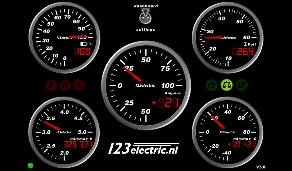
26 Screen-shots electronic dashboard 26
BMS-LiFePower. 123SmartBMS. Instruction manual
 BMS-LiFePower 123SmartBMS Instruction manual Index Introduction...2 Keep the batteries in perfect condition...2 Package contains (12 Volt, 4 cells)...3 Specs...3 Placing the cell modules...4 Mounting the
User Manual. BMS123 Smart
 User Manual BMS123 Smart Introduction After the introduction of affordable LiFePO4 batteries, off-grid solutions became available for wide public. It is vital that such batteries are charged very carefully.
123\SmartBMS. 123\SmartBMS manual V1.3. Albertronic BV The Netherlands
 123\SmartBMS 123\SmartBMS manual V1.3 Index Introduction... 2 Keep the batteries in perfect condition... 3 Package contents... 4 Specifications... 4 Placing the cell modules... 5 Mounting the IN Module...
User manual. BMS123 Smart
 User manual BMS123 Smart Introduction After the introduction of affordable LiFePO4 batteries, off-grid solutions became feasible. It is vital that such batteries are charged very carefully. In other words,
EV Power - A-Series 8 Cell, 16 Cell and 24Cell Chargers Installation & Usage Instructions.
 A-CHARGERS MANUAL 1.1 EV Power - A-Series 8 Cell, 16 Cell and 24Cell Chargers Installation & Usage Instructions. A-Series Charger Features - Simple to install and use, microprocessor control. - LiFePO4
EV Power - Battery Control Unit Instructions. 8 Cell 24V
 EV Power - Battery Control Unit Instructions. 8 Cell 24V PAGE 1 OF 12 BCU-EVPPAK Features - Simple to install and use, microprocessor control. - Low power requirement, just 15mA when switched on with relay
INSTALLATION INFORMATION
 INSTALLATION INFORMATION BMS ZE6000i-PCBT.xxxx / ver. 2 Programmable battery management system for Lithium Ion battery cells, for up to 32 round or prismatic cells, 10 to 400Ah NOTE: This installation
SOLN1 25 V2 Quick Start User Guide & Operating Recommendations
 SOLN1 25 V2 Quick Start User Guide & Operating Recommendations For Fully Assembled Units and Fast Build Kits Thank-you for supporting the SOLN1 Project by purchasing a SOLN1 25. This Quick Start User Guide
Rover Series. Rover 20A 40A Maximum Power Point Tracking Solar Charge Controller
 Rover Series Rover 20A 40A Maximum Power Point Tracking Solar Charge Controller 0 2775 E. Philadelphia St., Ontario, CA 91761 1-800-330-8678 Version 1.5 Important Safety Instructions Please save these
USER MANUAL GEBRUIKSAANWIJZING GEBRAUCHSANWEISUNG SKYLLA 24/100 3-PHASE CE
 USER MANUAL GEBRUIKSAANWIJZING GEBRAUCHSANWEISUNG SKYLLA 24/100 3-PHASE CE SECTIONS: ENGLISH 2 NEDERLANDS 17 DEUTSCH 37 Victron Energy BV De Paal 35 1351 JG Almere-Haven The Netherlands Article number
Lithium Power Pack LITHIUM-ION BATTERY SYSTEM. With epro Plus Battery Monitor
 Lithium Power Pack LITHIUM-ION BATTERY SYSTEM With epro Plus Battery Monitor LITHIUM-ION BATTERY SYSTEM After 2 years of research, testing and proving, and a further 5 years of infield sales, Enerdrive
Lithium Ion Battery Charger for Solar-Powered Systems
 Lithium Ion Battery Charger for Solar-Powered Systems General Description: The is a complete constant-current /constant voltage linear charger for single cell Li-ion and Li Polymer rechargeable batteries.
BMS16 v cell Lithium Battery Management System
 ZERO EMISSION VEHICLES AUSTRALIA http://www.zeva.com.au Safety Warning Although 8-16 cell lithium battery packs do not involve lethal voltages, they frequently involve dangerous amounts of current and
UniverSOL Charge Station
 UniverSOL Charge Station Group 17 Jonathan German Amy Parkinson John Curristan Brock Stoops Sponsored by Motivations Environmental Renewable Energy Carbon Emissions Power Demand Power Dependency Availability
Orion 2 BMS Operation Manual
 www.orionbms.com Orion 2 BMS Operation Manual The Orion BMS 2 by Ewert Energy Systems is the second generation of the Orion BMS. The Orion BMS 2 is designed to manage and protect Lithium ion battery packs
Virtual Ground for HV Boosters Calibration
 Dear all utracer users, I m writing these lines just to share my experience building my utracer, so that maybe someone could find it useful for his design. The construction of my utracer was very simple,
Lithium Power Supply
 Lithium Power Supply User Manual LPS 1200W-60Ah LPS 1500W-100Ah LPS 2500W-100Ah Compact lithium battery based power supply - for easy acces to 230V and 12V energy, everywhere! V1.1 Safety Instructions
Electronic Dynamo Regulator INSTRUCTION MANUAL. COPYRIGHT 2014 CLOVER SYSTEMS All Rights Reserved
 DRM TM DRM-HP TM Electronic Dynamo Regulator INSTRUCTION MANUAL COPYRIGHT 2014 CLOVER SYSTEMS All Rights Reserved INTRODUCTION The Clover Systems DRM is a state-of-the art all-electronic voltage and current
Great Chargers. Rating System. Bench-tested and editor-approved Text and photos by John Reid
 Great Chargers Bench-tested and editor-approved Text and photos by John Reid A charger is an essential investment that will pay dividends in the performance of your battery packs., safety features, and
EV Display User Guide
 EV Display User Guide CleanPowerAuto LLC Brief Description: EV Display is designed to track battery state of charge and other related data in battery powered Electric Vehicle. EV Display is primarily designed
Manual. Lynx Ion 24V/180Ah Lithium Ion Batteries
 Manual EN Lynx Ion 24V/180Ah Lithium Ion Batteries Copyrights 2012 Victron Energy B.V. All Rights Reserved This publication or parts thereof, may not be reproduced in any form, by any method, for any
UNIVERSAL CALIBRATOR M
 INTRODUCTION UNIVERSAL CALIBRATOR - 3001M Before going through the instruction manual for actual use of the instrument go through the specifications and take note of the following points carefully 1. No
INTRODUCTION. Specifications. Operating voltage range:
 INTRODUCTION INTRODUCTION Thank you for purchasing the EcoPower Electron 65 AC Charger. This product is a fast charger with a high performance microprocessor and specialized operating software. Please
Safe lithium ion high energy batteries. for electric propulsion. Chargers, on board supply EN LiFePO4
 Safe lithium ion high energy batteries for electric propulsion Chargers, on board supply EN 3-2016 LiFePO4 LiFePO4 aquawatt lithium batteries are made with advanced lithium iron phosphate cells. These
Features: Enhanced throttle response, excellent acceleration, linearity and driveability
 120A/150A ESC X-Car 120A/150A Series Sensored/Sensorless Brushless ESC for 1:8 scale Car or Truck Thank you for purchasing the X-Car Brushless Electronic Speed Controller (ESC). The X-Car 1:8 Scale 120A/150A
QUASAR ELECTRONICS KIT No WINDSCREEN WIPER CONTROLLER
 QUASAR ELECTRONICS KIT No. 1093 WINDSCREEN WIPER CONTROLLER General Description This is a very useful accessory for any car. It can adjust the frequency of operation of the windscreen wipers between once
LBC Series Battery Charger Instructions
 Ver1.2 Date: 2016/03/22 Version History Date Version Content 2014-05-19 1.0 Start Publishing 2015-03-12 1.1 Add BOOST, Charging Failure Alarm function 2016-03-22 1.2 Modify details : T:+86-769-23836636
BMW K1200LT / K1200RS Testing a Throttle Position Sensor (also called TPS)
") BMW K1200LT / K1200RS Testing a Throttle Position Sensor (also called TPS) Many hours were spent to test and validate the information furnished in this document. None of this information should be considered
BMW K1200LT / K1200RS Testing a Throttle Position Sensor (also called TPS) Many hours were spent to test and validate the information furnished in this document. None of this information should be considered
PCBA Instruction Manual
 PCBA 5010-4 Instruction Manual Disclaimer The PCBA 5010-4 has been designed and manufactured with careful consideration to the issues of safety from electrical shock, thermal hazards and RFI compliance
User Manual. T6 Tachometer. Online: Telephone: P.O. Box St. Petersburg, Florida 33736
 User Manual T6 Tachometer Online: www.phareselectronics.com Telephone: 727-623-0894 P.O. Box 67251 St. Petersburg, Florida 33736 Table of Contents Overview... 1 Description... 1 Wiring... 1 T6 Tachometer
Model 1:8 Beast-ZTWSS120A 1:8 Beast-ZTWSS150A. PN#Model Cont.Current 120A 150A. Burst Current 760A 1080A
 Alien Power System BEAST Series Sensored/Sensorless Brushless ESC for 1:8 scale Car or Truck Thank you for purchasing the Alien Power System Brushless Electronic Speed Controller (ESC). The Alien Power
Powerterm L120C Single Output PSU/Battery Chargers Model C2199A-1 (12V/8A) or Model C2199A-2 (24V/6A)
 or Model C2199A-2 (24V/6A)") A Complete solution for small battery-backed dc instrument power systems. DATASHEET Supply 12Vdc 8A or 24Vdc 6A loads Ideal for RTU s, dataloggers, remote field instrumentation, alarm systems, etc. where
A Complete solution for small battery-backed dc instrument power systems. DATASHEET Supply 12Vdc 8A or 24Vdc 6A loads Ideal for RTU s, dataloggers, remote field instrumentation, alarm systems, etc. where
Electronic Dynamo Regulator INSTRUCTION MANUAL. COPYRIGHT 2014 CLOVER SYSTEMS All Rights Reserved
 DRM TM DRM-HP TM Electronic Dynamo Regulator INSTRUCTION MANUAL COPYRIGHT 2014 CLOVER SYSTEMS All Rights Reserved INTRODUCTION The Clover Systems DRM is a state-of-the art all-electronic voltage and current
CONSONANCE CN3051A/CN3052A. 500mA USB-Compatible Lithium Ion Battery Charger. General Description: Features: Pin Assignment.
 CONSONANCE 500mA USB-Compatible Lithium Ion Battery Charger CN3051A/CN3052A General Description: The CN3051A/CN3052A is a complete constant-current /constant voltage linear charger for single cell Li-ion
C10325 v1.1. Thanks for your purchasing the intelligent and powerful charger.
 PFC programmable charger 90V~265VAC Input Thanks for your purchasing the intelligent and powerful charger. Read the ENTIRE instruction manual to become familiar with the features/functions of the device
Art. No. EC-315. Art. No. EC-330. Art. No. EC-340 SWITCH-MODE BATTTERY CHARGER CONTENTS IMPORTANT SAFETY PRECAUTIONS... 2
 SWITCH-MODE BATTTERY CHARGER CONTENTS IMPORTANT SAFETY PRECAUTIONS... 2 DESCRIPTION AND FEATURES... 3 CHARGING STAGES... 4 Art. No. EC-315 Art. No. EC-330 Art. No. EC-340 PROTECTIONS... 5 INSTALLATION...
0-28 vdc stabilized power supply with current control Amp
 0-28 vdc stabilized power supply with current control 0.002-10 Amp General Description This is a high quality power supply with a continuously variable stabilised output adjustable at any value between
Electronic Dynamo Regulator INSTRUCTION MANUAL. COPYRIGHT 2015 CLOVER SYSTEMS All Rights Reserved
 DR310 TM Electronic Dynamo Regulator INSTRUCTION MANUAL COPYRIGHT 2015 CLOVER SYSTEMS All Rights Reserved INTRODUCTION The Clover Systems DR310 is an allelectronic voltage and current regulator for dynamos
Notice Regarding this Upgrade. WARNING! Danger Potential
 Notice Regarding this Upgrade WARNING! Danger Potential Although this kit has been designed to be easy-to-install, and has been tested in many installations; caution must be exercised when installing this
Thank you for purchasing a Dillenger F1 Folding Bike, please read this manual before using your new electric bike.
 F1 Folding Bike Thank you for purchasing a Dillenger F1 Folding Bike, please read this manual before using your new electric bike. Before the first use, please fully charge the battery, this can take up
Technical Note. Management of Sealed Lead Acid Batteries in Reliable Small DC Standby Power Supply Systems
 Technical Note Management of Sealed Lead Acid Batteries in Reliable Small DC Standby Power Supply Systems Automation Products Introduction As more and more remote monitoring is installed on sites ranging
Coleman Air C440-HVM 440 Amp Diversion Controller Version 3.2
 Coleman Air C440-HVM 440 Amp Diversion Controller Version 3.2 With Extended Diversion Mode Page 1 Page 2 Introduction This diversion controller is the result of our many attempts to use the controllers
Elite Power Solutions Automatic Battery Control (ABC) Operation Manual
 Operation Manual") Elite Power Solutions Automatic Battery Control (ABC) Operation Manual Elite Power Solutions 335 E Warner Rd. STE 3 Chandler, AZ 85225 www.elitepowersolutions.com ABC Operation Manual Page 1 Table of Contents
Elite Power Solutions Automatic Battery Control (ABC) Operation Manual Elite Power Solutions 335 E Warner Rd. STE 3 Chandler, AZ 85225 www.elitepowersolutions.com ABC Operation Manual Page 1 Table of Contents
QUASAR KIT No VDC STABILIZED POWER SUPPLY WITH CURRENT CONTROL A
 QUASAR KIT No. 1138 0-30 VDC STABILIZED POWER SUPPLY WITH CURRENT CONTROL 0.002-3 A General Description This is a high quality power supply with a continuously variable stabilised output adjustable at
Just connect to the engine and go!
 For Boats all4 solar Australia Just connect to the engine and go! Lithium iron(ferite) batteries (LIFEPO04) only weigh 35-40% of lead acid batteries (depending on the size). Over 90% of the energy capacity
C&D VRLA Batteries Extended Run Time for Small UPS Machines
 TECHNICAL BULLETIN 41-7954 C&D VRLA Batteries Extended Run Time for Small UPS Machines 41-7954/0112/CD www.cdtechno.com Small UPS machines, in the range of 400 to 2500 VA, are typically used to provide
Advanced Information Subject to Changes
 Advanced Information Subject to Changes High Efficiency 30/60V, 100 Amps Active Management System for Lithium Ion Batteries Roboteq s is a battery management system designed for building cost-effective,
SUPER CAPACITOR CHARGE CONTROLLER KIT
 TEACHING RESOURCES ABOUT THE CIRCUIT COMPONENT FACTSHEETS HOW TO SOLDER GUIDE POWER YOUR PROJECT WITH THIS SUPER CAPACITOR CHARGE CONTROLLER KIT Version 2.0 Teaching Resources Index of Sheets TEACHING
Adafruit MicroLipo and MiniLipo Battery Chargers
 Adafruit MicroLipo and MiniLipo Battery Chargers Created by lady ada Last updated on 2016-10-11 06:25:10 PM UTC Guide Contents Guide Contents Overview Battery Types Plugging In USB Port Charge Indictator
Simple Free-Energy Devices
 Simple Free-Energy Devices There is nothing magic about free-energy and by free-energy I mean something which produces output energy without the need for using a fuel which you have to buy. Chapter 5:
Super Brain 989 The Pinnacle of Performance with Power to Spare User s Manual Model Rectifier Corporation
 Super Brain 989 The Pinnacle of Performance with Power to Spare User s Manual Temperature sensor jack Sensor included Model Rectifier Corporation Please read this entire manual including all Safety Cautions,
Super Brain 977. AC/DC Charger with Dual Output and Discharge Function. User s Manual. Model Rectifier Corporation
 Super Brain 977 AC/DC Charger with Dual Output and Discharge Function User s Manual Model Rectifier Corporation 80 Newfield Avenue Edison, NJ 08837-3817 Phone: 732-225-6360 www.modelrectifier.com Please
Written By: Markus. Step-by-Step guide how to replace a dead NICD-Battery with LiFePO-Batteries. Rollei 6000/6008 Battery LiFePO4 Replacement
 Rollei 6000/6008 Battery LiFePO4 Replacement Step-by-Step guide how to replace a dead NICD-Battery with LiFePO-Batteries. Written By: Markus ifixit CC BY-NC-SA www.ifixit.com Page 1 of 18 INTRODUCTION
Fenix UC35 V2.0 Flashlight
 Fenix UC35 V2.0 Flashlight Technical Parameters ANSI/PLATO FL1 Turbo High Med Low Moonlight Strobe 1,000 350 150 50 1 1,000 Lumen Output 2h 15min 4h 10min 10h 40min 28h 10min 800h / Runtime 266m 160m 98m
Types batteries. AGM Gel OpZs OpZv Lead Carbon LiFePO4 NCA Saltwater Zinc Bromine Etc,etc, etc, etc, etc, etc,
 Batteries Types batteries AGM Gel OpZs OpZv Lead Carbon LiFePO4 NCA Saltwater Zinc Bromine Etc,etc, etc, etc, etc, etc, Today focus on Victron batteries AGM Gel OpZs OpZv Lead Carbon LiFePO4 NCA Saltwater
Model No. DFC-X Support DIRECT FIRED DIGITAL TEMPERATURE CONTROL INSTALLATION, OPERATION, AND MAINTENANCE MANUAL
 Model No. DFC-X Support 877-351-4702 DIRECT FIRED DIGITAL TEMPERATURE CONTROL INSTALLATION, OPERATION, AND MAINTENANCE MANUAL This manual covers the following products: DFC-X TS-01 DFTD RDU DAT-12 PWM-10V
BASIC ELECTRICAL MEASUREMENTS By David Navone
 BASIC ELECTRICAL MEASUREMENTS By David Navone Just about every component designed to operate in an automobile was designed to run on a nominal 12 volts. When this voltage, V, is applied across a resistance,
MAX-FIRE AND E-FIRE ELECTRONIC DISTRIBUTORS
 INSTALLATION INSTRUCTIONS MAX-FIRE AND E-FIRE ELECTRONIC DISTRIBUTORS NOTE: This product is applicable to pre-1966 California and pre-1968 federally certified passenger cars. It is also applicable to non-emission
Super Brain 969 Pro AC/DC Delta Peak Charger with Dual Output and Discharge Function Instruction Manual Model Rectifier Corporation
 Super Brain 969 Pro AC/DC Delta Peak Charger with Dual Output and Discharge Function Instruction Manual Model Rectifier Corporation Please read this entire manual, including all Safety Cautions and Warnings
EV Display V4 User Guide
 EV Display V4 User Guide CleanPowerAuto LLC Brief Description: EV Display a.k.a SOC Gauge is designed to track battery state of charge and other related data in battery powered Electric Vehicle. EV Display
User Manual. Solar Charge Controller 3KW
 User Manual Solar Charge Controller 3KW 1 CONTENTS 1 ABOUT THIS MANUAL... 3 1.1 Purpose... 3 1.2 Scope... 3 1.3 SAFETY INSTRUCTIONS... 3 2 INTRODUCTION... 4 2.1 Features... 4 2.2 Product Overview... 5
Battery Power Inverters
 Battery Power Inverters Renogy 500W 1000W 2000W Pure Sine Wave Inverter Manual 2775 E. Philadelphia St., Ontario, CA 91761 1-800-330-8678 1 Version 1.4 Important Safety Instructions Please save these instructions.
Contents. Impressive technology lithium-ion batteries. 596 Cordless Working Overview Bosch Accessories for Power Tools 09/10
 Cordless operation 596 Cordless Working Overview Bosch Accessories for Power Tools 09/10 Contents 598 Batteries for Bosch cordless tools 609 Accessories for Bosch Cordless Torches GLI, PLI 606 Chargers
Competition Electronics, Inc
 Competition Electronics, Inc Turbo35-GFX LiPo User s Manual Addendum 1 Introduction This enhancement makes it possible to charge 1,2 and 3 cell LiPo battery packs with the T35-GFX. Now you can have the
CONGRATULATIONS ON YOUR PURCHASE OF YOUR THUNDER BATTERY CHARGER! For your personal safety read, understand and follow the information provided in
 CONGRATULATIONS ON YOUR PURCHASE OF YOUR THUNDER BATTERY CHARGER! For your personal safety read, understand and follow the information provided in this instruction manual & on the battery charger. This
Manual Installation & Operation
 Manual Installation & Operation Model: NCxxLxx 12A or 30A Solid State Solar Charging Regulator and 12A Load Controller. 231 Patent #: 5,642,030 Applies Page 1 Warnings When Installing, connect grounds,
Review: The West Mountain Radio CBA-IV Battery Analyzer Phil Salas AD5X. Figure 1: West Mountain Radio CBA-IV Battery Analyzer
 Review: The West Mountain Radio CBA-IV Battery Analyzer Phil Salas AD5X Figure 1: West Mountain Radio CBA-IV Battery Analyzer Introduction There has been more emphasis on battery power of late, particularly
VFD - Mitsubishi. VFD Manuals. Mitsubishi D700 VFD Installation. Mitsubishi FR-D700 VFD User Manual. Mitsubishi D700 Parallel Braking Resistors
 VFD - Mitsubishi VFD Manuals Mitsubishi D700 VFD Installation Mitsubishi FR-D700 VFD User Manual Mitsubishi D700 Parallel Braking Resistors VFD Wiring Diagram - Apollo Mitsubishi VFD to Interpreter Mitsubishi
Battery Fuel Gauge Specification
 Battery Fuel Gauge Specification Model Number: EJ-FG09 Doc No: SPE-FG-0068 Version: 01 Date: 2014-02-18 Prepared Checked Approved Sara Jess John Manufacturer reserves the right to alter or amend the approval
Modifying the exterior lighting of the Ram truck
 Modifying the exterior lighting of the Ram truck The Ram truck has been designed and developed using standard incandescent lights. These lights are controlled by a computerized module called the Central
Mitsubishi. VFD Manuals
 Mitsubishi VFD Manuals Mitsubishi D700 VFD Installation Mitsubishi FR-D700 VFD User Manual Mitsubishi D700 Parallel Braking Resistors VFD Wiring Diagram - Apollo Mitsubishi VFD to Interpreter Mitsubishi
LEADING BATTERY ENERGY STORAGE SOLUTIONS AVAILABLE FROM FREEDOM WON (DATA SHEETS AVAILABLE UPON REQUEST) Freedom Lite Home & Business
 Freedom Lite Home & Business") Freedom Lite LEADING BATTERY ENERGY STORAGE SOLUTIONS AVAILABLE FROM FREEDOM WON (DATA SHEETS AVAILABLE UPON REQUEST) Freedom Lite & Business Residential and Small to Medium Businesses Lithium storage
Freedom Lite LEADING BATTERY ENERGY STORAGE SOLUTIONS AVAILABLE FROM FREEDOM WON (DATA SHEETS AVAILABLE UPON REQUEST) Freedom Lite & Business Residential and Small to Medium Businesses Lithium storage
Electrical Systems. Introduction
 Electrical Systems Figure 1. Major Components of the Car s Electrical System Introduction Electricity is used in nearly all systems of the automobile (Figure 1). It is much easier to understand what electricity
The Benefits of Cell Balancing
 The Benefits of Cell Balancing Application Note AN141.0 Author: Yossi Drori and Carlos Martinez Introduction In the world of portable consumer products, the single biggest complaint voiced by the consumer
Critical Safety Elements in Smart Battery Pack Design
 Critical Safety Elements in Smart Battery Pack Design Smart Battery Data Expo Portable Design Conference January 15, 2002 Iilonga Thandiwe Staff Engineer Motorola Energy Systems Group Safety Circuit Design
THREE PHASE FAULT ANALYSIS WITH AUTO RESET ON TEMPORARY FAULT AND PERMANENT TRIP OTHERWISE
 THREE PHASE FAULT ANALYSIS WITH AUTO RESET ON TEMPORARY FAULT AND PERMANENT TRIP OTHERWISE ABSTRACT The project is designed to develop an automatic tripping mechanism for the three phase supply system.
Selected excerpts from the book: Lab Scopes: Introductory & Advanced. Steven McAfee
 Selected excerpts from the book: Lab Scopes: Introductory & Advanced Steven McAfee 1. 2. 3. 4. 5. 6. Excerpt from Chapter 1 Lab Scopes How do they work? (page 6) Excerpt from Chapter 3 Pattern Recognition
ECT Display Driver Installation for AP2 Module
 ECT Display Driver Installation for AP2 Module Overview The ECT Display Driver is a small module with a removable wire harness that mounts behind the driver's foot well cover. All wiring connections are
CBC-9130 / V 30A / 24V 15A Pro. Charger. Operation manual
 CBC-9130 / 9215 12V 30A / 24V 15A Pro. Charger Operation manual Keep this manual in a safe place for quick reference at all times. This manual contains important safety and operation instructions for correct
CYCLE LIFE 12V 5AH LITHIUM ION BATTERY RB5 LITHIUM ION BATTERY CAPACITY AT DIFFERENT CYCLES AT 100% DOD 99.
 RB5 LITHIUM ION BATTERY RB10 LITHIUM ION BATTERY 3.75 in. 95.25 mm CYCLE LIFE CAPACITY AT DIFFERENT CYCLES AT 100% DOD 100 cycles 500 cycles 99.7 96.3 1000 cycles 90.8 2 in. 50.8 mm 5.9 in. 149.86 mm 1500
I Charger.
 I Charger www.advanced-radio.com 1 Congratulations for choosing the Advanced Radio Intelligent Micro Charger - The worlds first Automatic Intelligent charger designed to mount directly in your giant scale
SL-02A Series Solar Power Intelligent Controller INSTRUCTION MANUAL VER1.1
 SL-02A Series Solar Power Intelligent Controller INSTRUCTION MANUAL VER1.1 Main features 1. Intelligent control is realized by using microprocessor and dedicated control calculation. 2. Four load working
Submerge Scooters. Background and History. Motor types. Lithium batteries
 Submerge Scooters Background and History Motor types Lithium batteries 2000 Submerge Scooters is born and starts using Tekna/Oceanic brushed motors and prop/shroud technology, which was originally developed
Technical Information (Read before use!)
") CHARGER ONE Technical Information (Read before use!) Caution!! The Charger One can be used to charge all types of Lupine rechargeable batteries. You must not use this charger with unrechargeable batteries!!
CHARGER ONE Technical Information (Read before use!) Caution!! The Charger One can be used to charge all types of Lupine rechargeable batteries. You must not use this charger with unrechargeable batteries!!
LiPo Battery Basics 3 - Charging
 Page 1 Published on Model Aviation (http://modelaviation.com) Home > LiPo Battery Basics 3 - Charging LiPo Battery Basics 3 - Charging Charging your batteries. Article by Jay Smith. Photos by MA Staff.
:34 1/15 Hub-4 / grid parallel - manual
 2016-02-24 11:34 1/15 Hub-4 / grid parallel - manual Hub-4 / grid parallel - manual Note: make sure to always update all components to the latest software when making a new installation. Introduction Hub-4
Enerdrive Lithium-Ion Battery System
 Enerdrive Lithium-Ion Battery System After 2 years of research, testing and proving, and a further 2 years of infield sales, Enerdrive has designed and created a COMPLETE Lithium Battery & Installation
EV Power Lithium Battery Management. BCU-MICRO-08-smd Instruction Manual.
 EV Power Lithium Battery Management. BCU-MICRO-08-smd Instruction Manual. Introduction The EV Power Battery Management System (BMS) is designed for Lithium Iron Phosphate (LiFePO4, LFP) batteries of capacity
TENSION LOAD. Product Overview
 Product Overview For almost 20 years Delphi has been a reliable source of tension load cells and solutions. What is the secret to our success Safety: Delphi s range of Tension load cells are designed to
TELEDYNE. PB 4213 June JUDSON TECHNOLOGIES A Teledyne Technologies Company TELEDYNE JUDSON TECHNOLOGIES TC8 TEMPERATURE CONTROLLERS
 TC8 TEMPERATURE CONTROLLERS Operating Instructions PB 4213 June 2004 The TC8 is a self contained Thermoelectric Cooler Temperature Controller for single and multistage TEC cooled photodetectors housed
Kelly HSR Series Motor Controller with Regen User s Manual V 3.3. Kelly HSR Opto-Isolated Series Motor Controller with Regen.
 Kelly HSR Opto-Isolated Series Motor Controller with Regen User s Manual HSR72601 HSR72801 HSR12401 HSR12601 HSR12901 HSR14301 HSR14501 HSR14701 Rev.3.3 Dec. 2011 Contents Chapter 1 Introduction... 2 1.1
Power Station. by Lithium USER MANUAL
 Power Station by Lithium USER MANUAL Table of Content Contents of packaging Gusto Power Station User Maintenance Chart Notice and Warning Before Using Gusto Power Station Overview Gusto Power Station Main
Quick Start Instructions For
 Quick Start Instructions For Power Management System DESCRIPTION Stevens is much more than just a solar charge controller and regulator. It is an intelligent power management system. performs the features
The RCS-6V kit. Page of Contents. 1. This Book 1.1. Warning & safety What can I do with the RCS-kit? Tips 3
 The RCS-6V kit Page of Contents Page 1. This Book 1.1. Warning & safety 3 1.2. What can I do with the RCS-kit? 3 1.3. Tips 3 2. The principle of the system 2.1. How the load measurement system works 5
Where There is Miboxer There is Power. User Manual. Model No.: C2-6000
 Where There is Miboxer There is Power User Manual Model No.: C2-6000 Introduction C2-6000 is a highly advanced battery charger, that includes a power bank function. The charger automatically adapts the
Programming of different charge methods with the BaSyTec Battery Test System
 Programming of different charge methods with the BaSyTec Battery Test System Important Note: You have to use the basytec software version 4.0.6.0 or later in the ethernet operation mode if you use the
specification (SSC Series )
") Sabvoton sine wave motor controller specification (SSC Series ) Version:V1.0 V1.0 Sep,201,2014 1 Contents Chapter 1 Chapter 2 Chapter 3 Chapter 4 Chapter 5 Chapter 6 Overview Main features and specification
Sabvoton sine wave motor controller specification (SSC Series ) Version:V1.0 V1.0 Sep,201,2014 1 Contents Chapter 1 Chapter 2 Chapter 3 Chapter 4 Chapter 5 Chapter 6 Overview Main features and specification
Platinum Folding Bike
 Platinum Folding Bike Thank you for purchasing a Dillenger Platinum Folding Bike, please read this manual before using your new electric bike. Before the first use, please fully charge the battery, this
Villager III. User Instructions. GTIS Power Systems
 Villager III User Instructions GTIS Power Systems power_systems@sil.org Introduction Figure 1: View showing Villager III and dc dc adapter The Villager III Power Bank may be used to power devices that
QUASAR ELECTRONICS KIT No ELECTRONIC CAR IGNITION
 QUASAR ELECTRONICS KIT No. 1058 ELECTRONIC CAR IGNITION General Description The advantages of having an electronic ignition in your car are well known. Let us mention them again: 1. Perfect burning of