EV Display V4 User Guide
|
|
|
- Brianne Mason
- 6 years ago
- Views:
Transcription
1 EV Display V4 User Guide CleanPowerAuto LLC Brief Description: EV Display a.k.a SOC Gauge is designed to track battery state of charge and other related data in battery powered Electric Vehicle. EV Display is primarily designed for LiFePo4 battery, but can be used with any other battery if properly calibrated. Tracking state of charge requires a reference point when battery is considered full since EV Display can only assume what actual SOC is, based on initial setup parameters. SOC data will only be correct if current reading is correct and reference point is reached on the regular basis. Reference point can be full pack voltage or the fact that amount of full charge taken by the battery is always a little more than amount of discharge, to compensate of battery inefficiency. Display will be more accurate if the battery is fully charged on a regular basis. If battery is always partially charged then EV Display reading may drift long term and will become less reliable. Its recommended to do a full charge at least weekly. Specifications: - Nominal power voltage 12V-64V. Min-Max power voltage range 10-80V. Power ground is not isolated from pack voltage sensing circuit, so optional isolated DC/DC converter is required if you need galvanic isolation between main pack and 12V power ground. - Power current 15mA without LCD backlight and 25mA with LCD backlight. LCD backlight comes on when any button is pressed or current reading is non-zero and stays on for 60 minutes. - Hall Effect current sensor with max range of +/-1000Amp. Best accuracy is guaranteed in the range +/- 600Amp. Sensor can be installed anywhere in the battery current circuit, which passes
2 both charge and discharge currents. Current reading resolution is 0.1A. With optional current splitter the range can be doubled to 2000Amp. - Monitored battery capacity from 1AH to 3000AH, in 1AH increments up to 50AH, then in 10AH increments. Configurable charge efficiency supports virtually any battery chemistry. - Main Board and LCD Display are connected with standard CAT5e or CAT6 Ethernet cable. 7ft shielded cable is supplied. If you need longer cable, replace with high quality shielded Ethernet cable of appropriate length. Poor cable quality may cause garbled data on LCD screen. - 3 output circuits, CMOS type 0-5V, 5mA max current limited by 1k internal resistors. Binary outputs for Full Charge and Low Fuel conditions, and analog 0-5V output to drive mechanical fuel gauge, can be used to drive OEM fuel gauges in existing vehicles. This requires separate amplifier circuit to increase signal power. - Pack voltage sensing ranges are 0V 64V and 0V - 350V. In low range voltage display resolution is 0.1V; in high range resolution is 1.0V. You must select the range you need when purchasing EV Display. - 2 lines LCD display shows any combination of 2 data points. Available data points are: Voltage, Amperage, AmpHours, SOC, Fuel Gauge, Temperature, Wattage, WattHours. - Display unit comes in a standard automotive 2 round gauge case, or square open board for custom mounting inside dash boards. - Optional external temperature sensor can be used to more accurately display battery temperature, by sticking the sensor onto one of battery terminals. Without external sensor displayed temperature is of the ambient environment around main board. - Serial port on the main board transmits battery data via serial stream. See the Appendix at the end of this manual for serial data format. Serial interface is at TTL levels (0-5V), galvanic isolated from the main pack. You need additional interface circuits to convert TTL signals to RS232, USB, etc. to interface with standard computer equipment. Such boards are available online. - SOC data and configuration parameters are stored in EEPROM, so data is retained when power is turned off. When power is turned back on, SOC data is restored to last know level, with 0.1AH accuracy. However, if main battery has been charged/discharged while EV Display was turned off, then SOC data will be inaccurate and will require a full charge to sync with 100% SOC level. Installation procedure: Display unit and sender unit are connected via shielded Ethernet cable. 7ft cable was supplied with your display, if you need longer cable you can buy it from any computer store. Make sure you get CAT5 or CAT6 high quality shielded cable to avoid high noise levels in EV.
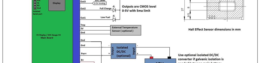
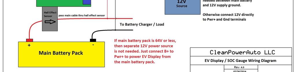
3 Display installs in a standard 2 gauge pod or appropriate size hole in the dash panel. You can also buy EV Display without the case, for custom install behind existing dash panels. NOTE: push-on tabs at the back of the display case are not used for anything, leave them disconnected. Main board has a Hall Effect sensor and a temperature sensor and must be mounted as close as possible to the battery pack to better reflect battery temperature. If you have insulated battery boxes, you should mount sender unit inside the battery box. Battery current must pass thru the hole of the Hall Effect sensor, so you must find a way to fit a bus bar thru the sensor s hole. It s possible to fabricate a custom bus bar to replace the standard bus bar which connects any 2 adjacent cells in your pack. Or you can use included 4 copper bar between any 2 connection points in your battery circuit and thread the copper bar thru Hall Effect sensor. Connect 12V power to Pwr+ and Gnd terminals and main pack voltage to B+ and Gnd terminals, as shown on the wiring diagram. If you need galvanic isolation between pack negative and your 12V supply ground, then you must use optional isolated DC/DC converter as shown on the wiring diagram. DC converter input voltage must be between 10V and 15V. Any spike above 15V could damage DC converter. NOTE: Be extra careful when working with pack voltage. For safety reasons, make wire connections at the main board before connecting them to the battery pack. Make sure voltage sensing wires are safely routed and secured between the pack terminals and the main board, so there is no chance of shorting them. It s a good idea to put an inline fuse at the pack terminals for extra safety. You can use any smallest fuse you can find, voltage sensing circuit takes less than 1mA. Make sure bottom of the main board is not touching any conducting surfaces; insulate the main board if needed, to prevent any potential contacts between exposed areas of the sender board and nearby conducting surfaces or terminals. NOTE: When powered directly, main board can take up to 80V power voltage, so if you are monitoring 12V-64V nominal batteries, then you can power main board directly from the main battery, by connecting B+ and Pwr+ terminals to the main battery. Initial setup procedure: When EV Display is powered on, it will enter normal data mode using previously set default parameters. To enter setup mode to change those parameters press and hold both buttons for 5 seconds. This will trigger zero point calibration and then first setup value will show on the screen. You must get to the 2 nd parameter within 20 seconds to prevent timeout of setup mode. Left button scrolls thru possible values; right button saves the value and switches to the next parameter. Once setup is completed those values are stored in EEPROM so you don t have to reconfigure all values every time EV Display is power cycled. Below is the listing of all setup values and their descriptions.
4 NOTE: If no buttons are pressed within 20 seconds after calibration then setup mode will time out and switch to data mode automatically, using previously stored values. Once you move to the 2 nd value, timeout is cancelled, so you can take your time setting all remaining values. This is initial calibration screen, it takes a few seconds to determine zero current levels, so current sensor can properly distinguish current direction and value. Its critical that calibration is done when there is no current flowing thru the battery pack, its best to completely turn off ignition and make sure the charger is turned off or disconnected from EV. Following setup parameters are available: V Range Voltage Range. Set this to match configuration of the main board. There are 2 available settings, to 64V and to 350V. This is typically set at the factory and should not change. PackSize - Battery pack capacity. Settings are from 1AH to 3000AH. Up to 50AH increments are 1AH, after 50AH increments are 10AH. Full Vlt Full Voltage. Set this to the maximum voltage your battery reaches at the end of charge. This will be used to sync the display s 100% SoC reading when the battery reaches this preset level. If for any reason you are not connecting voltage sensing circuit to your battery, set this value to zero. If for any reason your display is not reporting correct voltage levels ( wrong jumper settings, wrong V Range setting, etc ) you must set this value to some high level, up to maximum of 350V, so it will not interfere with display s SOC reading. Min SOC Minimal State Of Charge. This percentage value sets Empty Fuel Tank level, so the driver can go by Fuel Gauge reading and not completely deplete the battery, to preserve its lifecycles. For example, if this value is set to 20%, then Fuel Gauge will report 0% when SoC is still at 20%. If you desire to use your battery to its full capacity and/or want Fuel Gauge to reflect true SoC, then set this value to zero. CurrDir Current Direction. Hall Effect sensor reports direction of DC current passing thru the sensor. Its important for correct EV Display functionality that current is sensed in correct direction for charge/discharge. If you installed the sender board and then realized that its reporting wrong direction of the current, then flip this value to avoid having to reinstall the sender board. Current should be reporting with + sign during charge and without any signs during discharge. TempComp Temperature Compensation. At low temperatures batteries cannot supply their entire capacity due to slowdown of electrochemical processes. This percentage value reduces Fuel Gauge reading based on temperature drop, linearly from 25C to 0C and below,
5 such that Fuel Gauge reduction is equal this value at 0C ( freezing point ). For example, if you set this to 10% (recommended value for LiFePO4 cells), then Fuel Gauge will report 10% less capacity at 0C, linearly changing across wide temp range. This value only effects Fuel Gauge reading, SOC reading still remains true to battery capacity regardless of the temperature. NOTE: For this feature to work properly, mount the sender board as close to your cells as possible. If your cells are insulated, mount the sender board inside the battery box, so temp sensor at the sender board closely reflects cell s temperature. Low Fuel Low Fuel level. This percentage value determines the minimal Fuel Gauge level at which Low Fuel circuit is triggered. This is used for external signaling, such as OEM dash boards, etc. TempUnit Temperature Units. Set this to Fahrenheit ( F ) or Celsius ( C ). ChargeEff Charge Efficiency. This percentage value slows down rate of SoC climb during the charge, to compensate for battery losses during discharge. Recommended setting for LiFePO4 cells is 98%. This would be much less for Lead Acid batteries, depending on their Peukert value and battery application. For example, in EVs with high C rates, Peukert effect is more pronounced, so this value must be set lower to more accurately report SoC and Fuel Gauge values during partial charges. This setting must be tuned experimentally for best accuracy. Ideal setting will cause SOC to reach 100% at approximately the same time as charger is finishing up the full charge. NOTE: This feature assumes that Pack Size is set to actual useful capacity of the battery at high C rates, which is almost true for LiFePO4 cells, but not for Lead Acid batteries. Lead Acid battery will have smaller useful capacity than its rated capacity, so Pack Size should be set to useful capacity, so EV Display can reflect meaningful Fuel Gauge. DeadZone Dead Zone. In some cases when temperature fluctuations are wide and fast, EV Display might show non-zero current reading when not expected. This is due to imperfect temperature stability of Hall Effect sensors. EV Display software compensates for this, but in some extreme situations it might not work 100%, resulting in small current reading when not expected. Dead Zone allows ignoring small current readings when they are likely false (when small reading starts after zero reading). During charge, when current is dropping during CV phase, EV Display will count it even in the Dead Zone. If small reading persists for over 60 minutes, it will be considered as false reading and will be ignored. You can turn off this feature by setting this value to zero. Default 0.3A is recommended for best zero reading stability. TestMode Test Mode is designed for verification of external circuits. If you connect external mechanical fuel gauge, driven by EV Display s analog output, you can use test mode to make sure external gauge correctly follows EV Display s Fuel Gauge values. You can also test Full and
6 Low Fuel circuits using test mode. In test mode, SOC and Fuel Gauge values will automatically swing back and forth from 0 to 100% with 1% increments every second. Once you tested external circuits, repeat the setup routine and set this mode to Off. SensType Allows selection between standard 1000A sensor and specially designed optional current divider, allowing 2000A sensing range. Current divider will be offered as a separate upgrade option, at additional cost. CurScale Allows fine tuning of current reading, to match with trusted precision tools. You can leave it at default value of 0 since it already provides very good precision. If current reading does not match your other measurements and you trust those measurements more, then use this value to match EV Display reading with your own measurements. Idle Load Since EV Display cannot register very small loads you can preset such known loads, so if your battery is sitting idle for long periods, SOC value will be adjusted based on preset idle load value. You need to measure or estimate actual idle load in your system and set the value accordingly. Allowed range is 0mA 200mA. If you are not sure about your idle loads, leave this value at zero. Calib Since Hall Effect sensor is a bidirectional device, it s critical for correct EV Display functionality to maintain correct zero point, such that EV Display is showing zero amp reading when there is no current in the battery circuit. Initial calibration was done at the factory; however, another zero point calibration may be needed after you install your EV Display. Make sure to only use this option when your battery is idle, i.e. no charging or discharging at the time of calibration. Press left button to select Yes and then press right button to initiate calibration. Using EV Display: EV Display has the 2 line LCD screen, capable of showing 2 pieces of data independently. Press Left button to scroll thru available data on upper line, press Right button to scroll thru available data on the lower line. Any combination of data is possible on 2 lines. Following list explains all available data counters: Ah remaining AmpHour capacity of the battery. When EV Display is initially powered, it will show full capacity, 100% SoC and 100 Fuel Gauge. To sync the battery with EV Display, make sure the battery is fully charged after display is powered up. AmpHour capacity will not go over its preset max value even if the battery is still charging, which allows for top sync procedure.
7 10000 Wh remaining WattHour capacity of the battery. WattHour value is derived by multiplying AmpHour value and the Pack Voltage, so this value will be changing dynamically as voltage fluctuates with load. E F Graphical representation of the Fuel Gauge. Each of 6 bars corresponds to approximately 17% of capacity. 100% Fuel Digital Fuel gauge. 100% SoC State Of Charge A Instant current reading. + sign in front of the value indicates charge current. No sign indicates discharge current W Instant Wattage reading. This power value is derived by multiplying instant current and voltage. This is useful to estimate how much instant power is passing thru the battery circuit. In EVs, this value at certain preset driving conditions can be used to determine EV s efficiency compared to other EVs at the same driving conditions. 123 V Pk Instant voltage reading. 25C Tmp Instant temperature reading at the sender board location. EV Display wiring diagram: Complete wiring diagram is shown on the next page.
8
9 Serial Data protocol for SOC Gauge ( a.k.a EV Display ) There will be continuous stream of data packets with 1 second time interval between packets. Each data packet is an ASCII string of 45 characters, containing 10 data fields. Each field starts with label character and follows by decimal numeric data of constant length, padded by leading zeroes. Each string is terminated by return and new line characters, bytes 0x0D and 0x0A. Example of Data packet: B1H00000V000F000S000D0A00000W000000T000R00000 Data packet fields: B Battery address, typically 1, in multi-battery systems this will represent battery order 1 digit long H - AmpHours remaining, in 0.1Ah resolution, i.e. 123 = 12.3Ah 5 digits long V Volts, in 1V resolution for HV systems or 0.1V for LV systems, i.e. 123 = 12.3V 3 digits long F - Fuel Gauge, in percent, i.e. 100 = 100% 3 digits long S - SoC percent, in percent, i.e. 100 = 100% 3 digits long D Current direction, 1 charging, 0 discharging 1 digit long A - Amps instant, in 0.1A resolution, i.e. 123 = 12.3Amp 5 digits long W - Watts instant, in 1W resolution, i.e = 20000W 6 digits long T Temperature, in degrees, units depends on setup parameter 3 digits long R Reserved for future use 5 digits long Serial Port parameters: Baud Rate 9600 Data bits 8 Stop bits -1 Parity - none Copyright 2014 by CleanPowerAuto LLC
EV Display User Guide
 EV Display User Guide CleanPowerAuto LLC Brief Description: EV Display is designed to track battery state of charge and other related data in battery powered Electric Vehicle. EV Display is primarily designed
USER MANUAL MINI BMS DISTRIBUTED VERSION
 USER MANUAL MINI BMS DISTRIBUTED VERSION MiniBMS is a battery management system designed for LiFePo4 cells, used in Electric Vehicles. MiniBMS is designed to be reliable and cost effective solution; it
MiniBMS V3 User Manual
 MiniBMS V3 User Manual CleanPowerAuto LLC MiniBMS is a battery management system designed for LiFePo4 cells, used in Electric Vehicles. MiniBMS is designed to be reliable and cost effective solution; it
MiniBMS User Manual. Distributed version
 MiniBMS User Manual Distributed version MiniBMS is a battery management system designed for LiFePo4 cells, used in Electric Vehicles. MiniBMS is designed to be reliable and cost effective solution; it
MAGPOWR Spyder-Plus-S1 Tension Control
 MAGPOWR TENSION CONTROL MAGPOWR Spyder-Plus-S1 Tension Control Instruction Manual Figure 1 EN MI 850A351 1 A COPYRIGHT All of the information herein is the exclusive proprietary property of Maxcess International,
βeta 20A AUTO 12V/24V SOLAR CHARGE CONTROLLER WITH REMOTE METER
 βeta 20A AUTO 12V/24V SOLAR CHARGE CONTROLLER WITH REMOTE METER USER MANUAL βeta 20A AUTO 12V/24V SOLAR CHARGE CONTROLLER WITH REMOTE METER (OPTIONAL) CHARACTERISTICS LCD display: all systems parameters
EV Power - A-Series 8 Cell, 16 Cell and 24Cell Chargers Installation & Usage Instructions.
 A-CHARGERS MANUAL 1.1 EV Power - A-Series 8 Cell, 16 Cell and 24Cell Chargers Installation & Usage Instructions. A-Series Charger Features - Simple to install and use, microprocessor control. - LiFePO4
TTT802 Gearshift Controller, Part # R1N-S (Standard), -P (Paddleshift)
, -P (Paddleshift)") First, Sign and Date Bln 2009-03-9 Updated, Sign and Date Bln 200-04-29 (0) User Manual TTT802 Gearshift Controller Firmware for R--N-2- TTT802 Gearshift Controller, Part # 2-620-9-RN-S (Standard), -P
First, Sign and Date Bln 2009-03-9 Updated, Sign and Date Bln 200-04-29 (0) User Manual TTT802 Gearshift Controller Firmware for R--N-2- TTT802 Gearshift Controller, Part # 2-620-9-RN-S (Standard), -P
Installation and Maintenance Instructions. World Leader in Modular Torque Limiters. PTM-4 Load Monitor
 World Leader in Modular Torque Limiters Installation and Maintenance Instructions PTM-4 Load Monitor 1304 Twin Oaks Street Wichita Falls, Texas 76302 (940) 723-7800 Fax: (940) 723-7888 E-mail: sales@brunelcorp.com
Harris IRT Enterprises Digital Resistance Tester Model XP
 Harris IRT Enterprises Digital Resistance Tester Model 5012-06XP Specifications & Dimensions 2 Theory of Operation 3 Operator Controls & Connectors 4 Test Connections 5 Calibration Procedure 6-7 Options
PSIM Tutorial. How to Use Lithium-Ion Battery Model
 PSIM Tutorial How to Use Lithium-Ion Battery Model - 1 - www.powersimtech.com This tutorial describes how to use the lithium-ion battery model. Some of the battery parameters can be obtained from manufacturer
Elite Power Solutions Automatic Battery Control (ABC) Operation Manual
 Operation Manual") Elite Power Solutions Automatic Battery Control (ABC) Operation Manual Elite Power Solutions 335 E Warner Rd. STE 3 Chandler, AZ 85225 www.elitepowersolutions.com ABC Operation Manual Page 1 Table of Contents
Elite Power Solutions Automatic Battery Control (ABC) Operation Manual Elite Power Solutions 335 E Warner Rd. STE 3 Chandler, AZ 85225 www.elitepowersolutions.com ABC Operation Manual Page 1 Table of Contents
123\SmartBMS. 123\SmartBMS manual V1.3. Albertronic BV The Netherlands
 123\SmartBMS 123\SmartBMS manual V1.3 Index Introduction... 2 Keep the batteries in perfect condition... 3 Package contents... 4 Specifications... 4 Placing the cell modules... 5 Mounting the IN Module...
80V 300Ah Lithium-ion Battery Pack Data Sheet
 80V 300Ah Lithium-ion Battery Pack Data Sheet 80 V, 300 amp-hour capacity, maintenance-free energy storage, IP65 design, fully integrated BMS, integrated fuse and safety relay protection, highly configurable
Do isolate the power supply from other high power systems such as Stereos and Alarms
 Thank you for purchasing a Smart Ride Air Management System, AIRBAGIT.COM s premier flagship product. This system will meet all of your custom and utility needs and will provide you years of trouble free
Battery Beak User Manual
 Battery Beak User Manual Rev 1.0 Cross the Road Electronics, LLC www.crosstheroadelectronics.com Cross The Road Electronics, LLC Page 1 11/30/2011 Device Overview Lanyard loop for included lanyard. Tough
SP4 DOCUMENTATION. 1. SP4 Reference manual SP4 console.
 SP4 DOCUMENTATION 1. SP4 Reference manual.... 1 1.1. SP4 console... 1 1.2 Configuration... 3 1.3 SP4 I/O module.... 6 2. Dynamometer Installation... 7 2.1. Installation parts.... 8 2.2. Connectors and
PowerSTAR PS-2024-D. Maximum Power Point Tracking Solar Regulator. w w w. r o c s o l i d. c o m. a u. Contents
 w w w. r o c s o l i d. c o m. a u PowerSTAR PS-2024-D Maximum Power Point Tracking Solar Regulator Contents 1 Quick Start Guide... 2 2 Specifications... 3 2.1 General Operation... 3 2.2 Absolute Maximum
User manual. BMS123 Smart
 User manual BMS123 Smart Introduction After the introduction of affordable LiFePO4 batteries, off-grid solutions became feasible. It is vital that such batteries are charged very carefully. In other words,
SP5 INSTALLATION AND SETUP MANUAL
 SP5 INSTALLATION AND SETUP MANUAL 1 Installation 1.1 Introduction The SP5 System consists of a Data Acquisition unit (DAQ) with two complete Roller control channels, each Roller Control Channel consists
Owner s Manual. MG2000 Speedometer IS0211. for use with SmartCraft Tachometer
 Owner s Manual MG2000 Speedometer for use with SmartCraft Tachometer IS0211 rev. E ecr#6395 08/2006 4/5/05 Changes 12/21 Index Description Available Functions for display page 1 Default Screens page 1
SAILMON SYSTEM LOAD CELL BOX MANUAL. Sailmon LoadCellBox Manual V1.0 Page 1
 SAILMON SYSTEM LOAD CELL BOX MANUAL Sailmon LoadCellBox Manual V1.0 Page 1 Sailmon LoadCellBox Manual V1.0 Page 2 CONTENTS 1. Product Description...4 2. Technical Specifications...5 3. Installation...6
HP Series Smart Solar Charge Controller HP2430/2440/2450/2460 HP4830/4840 UserManual
 HP Series Smart Solar Charge Controller HP2430/2440/2450/2460 HP4830/4840 UserManual Dear users Thank you for choosing our product. Before using the product, please read this manual carefully.productfeatur
Operating and programming instructions at =AMPS or =WATTS REPLACED PERCENTAGE FROM LAST DISCHARGE
 TM-2030 TriMetric Battery Monitor Installation and User Guide TM 2030-RV Bogart Engineering CHARGING BATTERY REMINDERS when flashing-meets "CHARGED" criteria =TIME TO CHARGE =TIME FULL TO EQUALIZE =BATT.
Review: The West Mountain Radio CBA-IV Battery Analyzer Phil Salas AD5X. Figure 1: West Mountain Radio CBA-IV Battery Analyzer
 Review: The West Mountain Radio CBA-IV Battery Analyzer Phil Salas AD5X Figure 1: West Mountain Radio CBA-IV Battery Analyzer Introduction There has been more emphasis on battery power of late, particularly
SimpliPhi Power PHI Battery
 Power. On Your Terms. SimpliPhi Power PHI Battery INTEGRATION GUIDE: VICTRON Optimized Energy Storage & Management for Residential & Commercial Applications Utilizing Efficient, Safe, Non-Toxic, Energy
User Manual 123electric Battery Management System 123\BMS Revision 1.4 Augusts 2015
 User Manual 123electric Battery Management System 123\BMS Revision 1.4 Augusts 2015 Table of contents Introduction... 3 System structure... 3 Keep the batteries in a perfect condition : ALWAYS!... 5 Specifications...
TUTORIAL Lithium Ion Battery Model
 TUTORIAL Lithium Ion Battery Model October 2016 1 This tutorial describes how to use the lithium ion battery model. Some battery model parameters can be obtained from manufacturer datasheets, while others
Orion 2 BMS Operation Manual
 www.orionbms.com Orion 2 BMS Operation Manual The Orion BMS 2 by Ewert Energy Systems is the second generation of the Orion BMS. The Orion BMS 2 is designed to manage and protect Lithium ion battery packs
 WWW.MORETRACTION.COM TMS-5500-SL ELECTRONIC TRACTION CONTROL US PATENT 6,577,944 Other Patents Pending COPYRIGHT NOTICE Copyright 1999-2013 Davis Technologies, LLC. All rights reserved. Information in
Model 8000XL OPERATOR MANUAL
 Model 8000XL OPERATOR MANUAL DORAN SCALES, INC. 1315 PARAMOUNT PKWY. BATAVIA, IL 60510 1-800-262-6844 FAX: (630) 879-0073 http://www.doranscales.com MANUAL REVISION: 1.0 MAN0191 10/3/2005 INTRODUCTION
USER MANUAL W ONBOARD GENERATOR SYSTEM
 80 W ONBOARD GENERATOR SYSTEM USER MANUAL 1.4 1 1. Description Onboard Generator system consists of a Generator Power Unit (GPU), belt driven industrial-grade coreless generator, mounts and wiring necessary
NEC Energy Solutions ALM 12V35 Batteries with
 NEC Energy Solutions ALM 12V35 Batteries with Charging Morningstar NEC Energy Solar Solutions Charge Controllers This application note was developed through a collaborative effort between NEC Energy Solutions
Observe all necessary safety precautions when controlling the soft starter remotely. Alert personnel that machinery may start without warning.
 Introduction OPERATING INSTRUCTIONS: MCD REMOTE OPERATOR Order Codes: 175G94 (for MCD 2) 175G361 + 175G9 (for MCD 5) 175G361 (for MCD 3) 1. Introduction 1.1. Important User Information Observe all necessary
BMS16 v cell Lithium Battery Management System
 ZERO EMISSION VEHICLES AUSTRALIA http://www.zeva.com.au Safety Warning Although 8-16 cell lithium battery packs do not involve lethal voltages, they frequently involve dangerous amounts of current and
AFP MEA Mini Electrical Rotary Actuator User s Instructions
 AFP MEA Mini Electrical Rotary Actuator User s Instructions Please read and understand the instruction related to this product. These are User s Instructions and the AN-05 application notes. WARNING Failure
BMS-LiFePower. 123SmartBMS. Instruction manual
 BMS-LiFePower 123SmartBMS Instruction manual Index Introduction...2 Keep the batteries in perfect condition...2 Package contains (12 Volt, 4 cells)...3 Specs...3 Placing the cell modules...4 Mounting the
PQube 3 Modbus Interface
 PQube 3 Modbus Interface Reference manual Revision 1.9 Modbus Interface Reference Manual 1.9- Page 1 Table of Contents 1. Background... 3 2. Basics... 3 2.1 Registers and Coils... 3 2.2 Address Space...
VC-4820 Programmable DC-DC Converter with Battery Charger function USER'S MANUAL
 1. INTRODUCTION VC-4820 Programmable DC-DC Converter with Battery Charger function USER'S MANUAL This MCU controlled Step Down DC-DC Converter has a digitally adjustable output in 0.2V increments. This
Quick Start Instructions For
 Quick Start Instructions For Power Management System DESCRIPTION Stevens is much more than just a solar charge controller and regulator. It is an intelligent power management system. performs the features
OPERATING INSTRUCTIONS
 Manual No LI-4159-MIL OPERATING INSTRUCTIONS OPERATING INSTRUCTIONS NAVY BATTERY CHARGER / ANALYZER P/N 4159-MIL MODEL CA-1550-MIL NSN: 4920-01-498-2543 Issued By: LamarTechnologies LLC 14900 40th Ave.
ALM-Inline. Accurate Lambda Meter V1.1.2 COPY RIGHTS ECOTRONS LLC ALL RIGHTS RESERVED.
 ALM-Inline Accurate Lambda Meter V1.1.2 COPY RIGHTS ECOTRONS LLC ALL RIGHTS RESERVED Http://www.ecotrons.com Note: If you are not sure about any specific details, please contact us at info@ecotrons.com.
Serial adapter 1.0 V10 Fadec to serial comunications
 Serial adapter 1.0 V10 Fadec to serial comunications Users Guide. Torrent d en Puig, 31. 08358, Arenys de Munt, Barcelona,Catalonia,Spain E-mail: info@xicoy.com. Fax: +34 933 969 743 web: www.xicoy.com
Product Manual. Part Number: MVP-193 Mefi-6 ECU Revision: 1.0
 Product Manual Part Number: MVP-193 Mefi-6 ECU Revision: 1.0 Copyright Controls, Inc. P.O. Box 368 Sharon Center, OH 44274 Phone 330.239.4345 Fax 330.239.2845 www.controlsinc.com TABLE OF CONTENTS PRIOR
APSX WIDEBAND D2 AFR CONTROLLER GAUGE. Installation and User Manual. APSX WIDEBAND D2 Manual V1.0
 APSX WIDEBAND D2 AFR CONTROLLER GAUGE Installation and User Manual APSX WIDEBAND D2 Manual V1.0 You purchased a wideband gauge! BENCH TEST BEFORE INSTALLING IT! USE A RELIABLE 12V POWER > 5AMP Stock (OEM)ECU
INSTRUCTIONS FOR TRI-METRIC BATTERY MONITOR May 8, 1996
 INSTRUCTIONS FOR TRI-METRIC BATTERY MONITOR May 8, 1996 PART 2: SUPPLEMENTARY INSTRUCTIONS FOR SEVEN TriMetric DATA MONITORING FUNCTIONS. A: Introduction B: Summary Description of the seven data monitoring
REMOVAL OF FACTORY GAUGE ULTRA FLHT & FLHX (STREET GLIDE
 MCL-36K-SPD Thank you for purchasing the Dakota Digital MCL-36K-SPD gauge for your Harley Davidson Touring bike. This kit is designed to be a direct, plug in replacement for all touring models from 2004
Sól Dual Voltage Buck Boost Solar Charge Controller Connection & Operation V1.00
 Sól Dual Voltage Buck Boost Solar Charge Controller Connection & Operation V1.00 Connection Instructions Remove Bottom 4 cover to attach wires to terminal blocks then attach cover and flip over for mounting
WG5Kxxx Modular DC-converter system
 Short description WG5Kxxx Modular DC-converter system General characteristics The modular DC converter system is useful for the DC coupling of various electrical components (sources, sinks, storages) with
Orion BMS Purchasing Guide Rev. 1.2
 www.orionbms.com Orion BMS Purchasing Guide Rev. 1.2 Main Components... 2 Orion BMS Unit... 2 Current Sensor... 4 Thermistors... 5 CANdapter... 6 Wiring Harnesses... 7 Cell voltage tap wiring harnesses...
VC-30 / VC-40 Programmable DC-DC Converter with Battery Charger function USER'S MANUAL
 1. INTRODUCTION VC-30 / VC-40 Programmable DC-DC Converter with Battery Charger function USER'S MANUAL This MCU controlled Step Down 24V to 12V DC-DC Converter has a programmable 12.0 to 15.0V output in
User Manual. BMS123 Smart
 User Manual BMS123 Smart Introduction After the introduction of affordable LiFePO4 batteries, off-grid solutions became available for wide public. It is vital that such batteries are charged very carefully.
HousePower BMS. CleanPowerAuto LLC
 HousePower BMS CleanPowerAuto LLC Features: Designed for 12V and 24V LiFePo4 battery banks, replacing Lead Acid house banks in marine and RV applications, with minimal changes to existing systems and wiring
Dual Voltage Solar Power Charge Controller Board Connection & Operation V2.xx
 Dual Voltage Solar Power Charge Controller Board Connection & Operation V2.xx Connection Instructions 1) Mount Board to a panel (Wood or Metal) using supplied spacers and screws. 2) Solar Start up 18 volts,
PWM Charge Controller with LCD Display 30A. User Manual
 PWM Charge Controller with LCD Display 30A User Manual 1 Product Features 1. 12V/ 24 V system voltages are automatically recognized. 2. Charging program options for sealed, GEL and flooded lead-acid batteries
Lear 3.3kW High Voltage Charger
 Lear 3.3kW High Voltage Charger Copyright 2013. EVTV LLC INTRODUCTION This manual describes the Lear 3.3kW high voltage battery charger. The Lear 3.3kW is used on a number of major automotive manufacturer
INSTALLATION INFORMATION
 INSTALLATION INFORMATION BMS ZE6000i-PCBT.xxxx / ver. 2 Programmable battery management system for Lithium Ion battery cells, for up to 32 round or prismatic cells, 10 to 400Ah NOTE: This installation
Fuel level sensors Strela - Users manual. Fuel level sensors Strela. Users manual
 Fuel level sensors Strela Fuel level sensors Strela - Users manual Users manual 10.09.2011 Sapsan Control Co Ltd www.skontrol.ru Russia, Chelyabinsk 2011 Fuel level sensors Strela - Users manual Content
ELECTRONIC TRACTION CONTROL USER MANUAL
 DRAG-SPORTSMAN N2O For ELECTRONIC TRACTION CONTROL USER MANUAL TELEPHONE 828.645.1505 FAX 828.645.1525 WWW.MORETRACTION.COM US PATENT 6,577,944 Disclaimer...2 Introduction... 3 How Does It Work. 4 Installation...
D2020N. Negative Ground 20A Max. Charge 20A Max. Load. Advanced Solar Charge Controller. DINGO User Guide. Read this before installing. Ver 1.
 D2020N Negative Ground 20A Max. Charge 20A Max. Load Advanced Solar Charge Controller DINGO User Guide Read this before installing Ver 1.5 031017 2 This is not an MPPT device: There is no voltage conversion.
Support. EMROL Your power partner
 Support Support Part one What is and how to use / upgrade the software / firmware / manual How to start a capacity test Interpreting the results after a test is finished Read out the results with the BITS-software
Model: AEM14 Analog Engine Monitor
 Model: AEM14 Analog Engine Monitor Installation and Setup Manual Version 1 Table of Contents Monitor Overview DMK Engine Monitor Kit Section 1: Initial Setup 1.1 Internal Settings Switches Figure 1. AEM14
Intercomp. PT300 Users Manual. Manual #: E
 Intercomp PT300 Users Manual Manual #: 700028-E Table of Contents INTRODUCTION...3 SPECIFICATIONS...3 Controls...3 Electrical...3 Performance...3 Environmental...3 Physical...3 Weights and Measures...4
LTX RF LEVEL SENSOR. Instruction Manual
 LTX RF LEVEL SENSOR Instruction Manual FOR MODELS LTX01, LTX02, LTX05 Intempco Document No: LTX - M01 Rev. 1 Issue Date: April 2005 LTX01 RF LEVEL SENSOR USER MANUAL Software Rev : Rev. Date : June 2004
USERS MANUAL MCD REMOTE OPERATOR
 USERS MANUAL MCD REMOTE OPERATOR Order Code: 175G9004, 175G3061 Contents Contents Introduction...2 Important User Information...2 General Description...2 Symbols Used in this Manual...2 Installation...3
Modbus Register Map:Galaxy VM (3: kVA 400/480V)
") Modbus Register Map:Galaxy VM (3:3 50-225kVA 400/480V) Part number: 990-9692 Notes:. 6-bit registers are transmitted MSB first (i.e. big-endian). 2. INT32 and UINT32 are most-significant word in n+0, least
Modbus Register Map:Galaxy VM (3:3 50-225kVA 400/480V) Part number: 990-9692 Notes:. 6-bit registers are transmitted MSB first (i.e. big-endian). 2. INT32 and UINT32 are most-significant word in n+0, least
Battery Capacity Versus Discharge Rate
 Exercise 2 Battery Capacity Versus Discharge Rate EXERCISE OBJECTIVE When you have completed this exercise, you will be familiar with the effects of the discharge rate and battery temperature on the capacity
Model TUR-200D Turbine Flowmeter
 General Specifications Model TUR-200D Turbine Flowmeter Liquid flows through the turbine housing causing an internal rotor to spin. As the rotor spins, an electrical signal is generated in the pickup coil.
SP PRO KACO Managed AC Coupling
 SP PRO KACO Managed AC Coupling Introduction The SP PRO KACO Managed AC Coupling provides a method of linking the KACO Powador xx00 and Powador xx02 series grid tie inverters to the SP PRO via the AC Load
Turnigy FATBOY 8. User s Guide. Copyright 2012 Hobby King 01/18/2012
 Turnigy FATBOY 8 User s Guide Copyright 2012 Hobby King 01/18/2012 This Turnigy product manufactured in Singapore by LEO Energy Pte Ltd, www.revolectrix.com Contents Contents... 2 About FATBOY 8... 4 Using
ENGLISH SAFETY INSTRUCTIONS. Recommendations for safe operation. Operator safety. General warnings
 Safety and use instructions LifeSpeed iq TM - 3-phase chargers ENGLISH SAFETY INSTRUCTIONS GOALS OF THIS MANUAL This manual is aimed at any authorized personnel wanting to use a 3-phase LifeSpeed iq TM
Digital-Control and Programmable DC Power Supply Models: , , , & User Manual
 Digital-Control and Programmable DC Power Supply Models: 72-2535, 72-2540, 72-2545, 72-2550 & 72-10480 User Manual Page 19/05/16 V1.0 Safety Symbols This chapter contains important safety instructions
Idle Timer Controller - A-ITC620-A Chevrolet Express/GMC Savana
 Introduction An ISO 9001:2015 Registered Company Idle Timer Controller - A-ITC620-A1 2009-2019 Chevrolet Express/GMC Savana Contact InterMotive for additional vehicle applications The A-ITC620-A1 is an
Glow Plug for E Series Only
 Charging the Battery - Do not charge the battery, with a charger using negative discharge pulses, when connected to the ECU. This will destroy the electronics of the ECU. The only method is to disconnect
Idle Timer Controller - A-ITC620-A Chevrolet Express/GMC Savana
 An ISO 9001:2008 Registered Company Idle Timer Controller - A-ITC620-A1 2009-2018 Chevrolet Express/GMC Savana Contact InterMotive for additional vehicle applications Introduction The A-ITC620-A1 is an
CRAGG RAILCHARGER Instruction Manual for 20SMC-12V 20SMC-24V 40SMC-12V 40SMC-24V 60SMC-12V 80SMC-12V
 CRAGG RAILCHARGER for 20SMC-12V 20SMC-24V 40SMC-12V 40SMC-24V 60SMC-12V 80SMC-12V Contents 1 Warnings, Cautions, and Notes... 1 2 Description... 2 3 Features... 2 3.1 STANDARD FEATURES... 2 3.2 OPTIONAL
Model 2500 Horsepower Computer System User Manual
 Model 2500 Horsepower Computer System User Manual Manufacturered by: Ries Labs, Inc. 2275 Raven Road Farina, IL 62838 Phone: (618) 238-1400 email: admin@rieslabs.com Table of Contents Description ----------------------------------------------------------------
Open-circuit voltages (OCV) of various type cells:
 of various type cells:") Open-circuit voltages (OCV) of various type cells: Re-Chargeable cells: Lead Acid: 2.10V/cell to 1.95 NiMH and NiCd: 1.20 V/cell Li Ion: 3.60 V/cell Non-re-chargeable (primary) cells: Alkaline: 1.50 V/cell
Open-circuit voltages (OCV) of various type cells: Re-Chargeable cells: Lead Acid: 2.10V/cell to 1.95 NiMH and NiCd: 1.20 V/cell Li Ion: 3.60 V/cell Non-re-chargeable (primary) cells: Alkaline: 1.50 V/cell
SOLAR SMART. 12/24V 20Amp MPPT Solar Charge controller with Ethernet
 SOLAR SMART 12/24V 20Amp MPPT Solar Charge controller with Ethernet Embedded web pages, SNMP support, output port for external Relay board and GSM SMS unit port USER MANUAL PLEASE READ THIS MANUAL CAREFULLY
ALIANT ULTRALIGHT BATTERY is a product by ELSA Solutions S.r.l
 Pg. 2 / 32 LIFEPO4 BATTERY CHARGER CB1203 3 Amp charger / Xtra Small Compact and inexpensive battery charger!!! Use with Aliant X, X-P and YLP series / from 2 to 20Ah ACCESSORIES This battery charger is
CPi. CoiL PACK IGNiTioN FOR AViATiON. For 4,6 and 8 cylinder 4 stroke applications. Please read the entire manual before beginning installation.
 1 CPi CoiL PACK IGNiTioN FOR AViATiON Coil pack (4 cylinder) Coil pack (6 cylinder) For 4,6 and 8 cylinder 4 stroke applications. Please read the entire manual before beginning installation. Software version
mass flowmeter for compressed air
 mass flowmeter for compressed air VARIOMASS ECO pressure and temperature compensated easy and cost effective installation of the sensor no pressure loss caused by the sensor no moving parts, i.e. maintenance
W2175 LOAD INDICATOR Calibration (Version cal2175 V2.0)
") W2175 LOAD INDICATOR Calibration (Version cal2175 V2.0) Crane Warning Systems Atlanta 1-877-672-2951 Toll Free 1-678-261-1438 Fax www.craneindicators.com sales@craneindicators.com -1- CALIBRATION DATA
W2175 LOAD INDICATOR Calibration (Version cal2175 V2.0) Crane Warning Systems Atlanta 1-877-672-2951 Toll Free 1-678-261-1438 Fax www.craneindicators.com sales@craneindicators.com -1- CALIBRATION DATA
IPC-PC Intelligent Pump Control Operation Manual
 IPC-PC Intelligent Pump Control Operation Manual OEM Original Equipment Manufacturer Stewart & Stevenson Control System Group 10750 Telge Road Houston, Texas 77095 Stewart & Stevenson Services, Inc. Introduction
Super Brain 989 The Pinnacle of Performance with Power to Spare User s Manual Model Rectifier Corporation
 Super Brain 989 The Pinnacle of Performance with Power to Spare User s Manual Temperature sensor jack Sensor included Model Rectifier Corporation Please read this entire manual including all Safety Cautions,
UNIVERSAL CALIBRATOR M
 INTRODUCTION UNIVERSAL CALIBRATOR - 3001M Before going through the instruction manual for actual use of the instrument go through the specifications and take note of the following points carefully 1. No
NexSysLink. Operation Manual. NMEA 2000 SAE J1939 Indmar Engines. CAN Instruments Product Family
 NexSysLink CAN Instruments Product Family Operation Manual NMEA 2000 SAE J1939 Indmar Engines Contact Beede Beede Electrical Instrument Company, Inc. 88 Village Street Penacook, NH 03303 (603) 753-6362
Sonnenschein Lithium HC (High Current)
") Sonnenschein Lithium HC (High Current) Sonnenschein Lithium is a range of, 18 and 36 Volt Lithium battery modules. These Lithium modules offer significant cycling, charge time, weight and volume improvements
Sonnenschein Lithium HC (High Current) Sonnenschein Lithium is a range of, 18 and 36 Volt Lithium battery modules. These Lithium modules offer significant cycling, charge time, weight and volume improvements
ArchWeigh 2000 Conveyor Belt Scale Weigh Idler For Single or Multiple Scale Bases
 ArchWeigh 2000 Conveyor Belt Scale Weigh Idler For Single or Multiple Scale Bases Installation & Operation Manual Rev. 4/01 Post Office Box 1760 5929 Benton Road Paducah, KY 42002-1760 PHONE: 800-553-4567
Idle Timer Controller - ITC515-A Ford Transit Contact InterMotive for additional vehicle applications
 An ISO 9001:2008 Registered Company Idle Timer Controller - ITC515-A 2015-2018 Ford Transit Contact InterMotive for additional vehicle applications Overview The ITC515-A system will shut off gas or diesel
ELM327 OBD to RS232 Interpreter
 OBD to RS232 Interpreter Description Almost all new automobiles produced today are required, by law, to provide an interface from which test equipment can obtain diagnostic information. The data transfer
OPTI-Solar SC MPPT Series
 www.opt i -sola r. c o m OPTI-Solar SC MPPT Series SOLAR CHARGE CONTROLLER SC-50 / SC-80 / SC-80X / SC-160X MPPT Installation and Operation Manual CONTENTS Introduction... Feature... Specification... Dimension...VII
Rover Series. Rover 20A 40A Maximum Power Point Tracking Solar Charge Controller
 Rover Series Rover 20A 40A Maximum Power Point Tracking Solar Charge Controller 0 2775 E. Philadelphia St., Ontario, CA 91761 1-800-330-8678 Version 1.5 Important Safety Instructions Please save these
Lingenfelter ECSS-001 Ethanol Content Sensor Signal Simulator Installation & Operating Instructions
 Lingenfelter ECSS-001 Ethanol Content Sensor Signal Simulator Installation & Operating Instructions PN: L460350085 Revision - 1.6 Lingenfelter Performance Engineering 1557 Winchester Road Decatur, IN 46733
FM200 FLOW/NO-FLOW MONITOR INSTALLATION AND TECHNICAL MANUAL 120 VAC MODEL 6/1/2017
 FM200 FLOW/NO-FLOW MONITOR INSTALLATION AND TECHNICAL MANUAL 120 VAC MODEL 6/1/2017 Maxi-Tronic, Inc. 417 Wards Corner Road Loveland, OH 45140 513.398.2500 800.659.8250 FAX: 513.398.2536 info@maxitronic.com
Xtalin Accumulator Monitoring System and. Xtalin Accumulator Balancing System devices
 www.xtalin.com lagler@xtalin.com Xtalin Accumulator Monitoring System and Xtalin Accumulator Balancing System devices Datasheet - Public Table of content 1. List of abbreviations... 4 2. List of all AMS
CPW Current Programmed Winder for the 890. Application Handbook. Copyright 2005 by Parker SSD Drives, Inc.
 CPW Current Programmed Winder for the 890. Application Handbook Copyright 2005 by Parker SSD Drives, Inc. All rights strictly reserved. No part of this document may be stored in a retrieval system, or
CLA-VAL e-drive-34. User Manual. Motorised Pilots. CLA-VAL Europe LIN072UE - 04/16
 User Manual CLA-VAL Europe www.cla-val.ch cla-val@cla-val.ch 1 - LIN072UE - 04/16 Table of Contents 1 Introduction... 3 1.1 Precautions Before Starting... 3 1.2 Troubleshooting... 3 1.3 General Disclaimer...
CONTROL BOX. Wiring the control box into the vehicle. +12V
 CONTROL BOX Once the display panel is in place, mount the control box within the connecting cable's distance (approximately 3 feet) and secure to the underside of the dashboard. This case does not have
ATOTH-G Series BLDC Motor Controller. User s Manual
 ATOTH-G Series BLDC Motor Controller User s Manual Contents Chapter One Summary...1 Chapter Two Main Features and Specifications.2 2.1 Basic Functions...2 2.2 Features... 5 2.3 Specifications...6 Chapter