Tmax. Technical catalogue. Low voltage moulded-case circuit-breakers up to 630 A. Preliminary - 1SDC210004D0202
|
|
|
- Darlene Ryan
- 5 years ago
- Views:
Transcription

1 Technical catalogue Tmax Low voltage moulded-case circuit-breakers up to 630 A Preliminary - 1SDC210004D0202
2 O

3 VERVIEW MAIN CHARACTERISTICS THE RANGES ACCESSORIES CHARACTERISTIC CURVES AND TECHNICAL INFORMATION WIRING DIAGRAMS OVERALL DIMENSIONS ORDERING CODES

4


5 GENERATION Tmax has grown. ABB SACE s experience in designing and manufacturing moulded-case circuit-breakers has made it possible to create apparatus which, up to 630 A, allows any application to be faced practically and simply. The new Tmax have been thought up to work together, to help you carry out selections and correct sizing, to make installation simpler, but above all to give you top level performances. The latest generation technology is present for the first time even in the smallest sizes, to reach protection releases with integrated dialogue units. With Tmax you have everything you need TMAX. BE FREE. at hand to make your job easier, from all types of accessories and terminals. The T Generation grows, and so does freedom. The Tmax T4 and T5 circuitbreakers have obtained the prestigious INTEL Design 2003 Augusto Morello award in the Product Technologies and Production processes section.

6


7 ECHNOLOGY It was not easy to find solutions which would allow the Tmax circuit-breakers to achieve such high performances in such limited dimensions, but thanks to the experience which has been recognised to a leader such as ABB SACE for decades, the objectives we had set ourselves have been achieved. So this has meant TMAX. BE FREE TO RIDE THE MOST ADVANCED TECHNOLOGY. being able to equip such a small circuit-breaker as the T2 with an electronic release, to fit the apparatus with new arcing chambers which allow the arc extinction time to be reduced, or, still further, to provide double insulation for ever greater safety right from the smallest size. A complete series of latest generation releases is available, from the electronic ones also fitted with an integrated dialogue unit, to the thermomagnetic, or magnetic only ones - all interchangeable. And residual current releases up to 630 A, among which the exclusive B type residual current release stands out, sensitive to continuous fault currents and frequencies up to 1000 Hz. The new Tmax T4 and T5 are an example of the great technology expressed by this family of apparatus with high breaking capacity, Ics at 100% of Icu and high limitation of the specific let-through energy. Being free is also all this.

8


9 IZING All the apparatus in the Tmax family comes from optimisation of installation sizing. With T1,T2 and T3 you can find the ideal apparatus for sizing an installation up to 250 A, and with T4 and T5 up to 630 A. Furthermore, with the latter, high selectivity values are obtained for optimal coordination with other apparatus. You can also choose the best solution for motor TMAX. BE FREE TO CHOOSE OPTIMAL SIZING. protection up to 250 kw at 400 V in alternating current. Higher performances in less space. More applications up to 630 A. Easier selection of the apparatus and accessories. Optimal sizing of the installation and better protection of cables, busbar ducts and supports. Less space required in the switchgear and in the metal structures. Less oversizing and therefore lower costs. Less time for coordinating the installations. Fewer stock complications. With Tmax, all the solutions needed can be chosen, as well as that of feeling freer to choose.

10


11 NSTALLATION Having apparatus available with smaller dimensions than all the others on the market undoubtedly offers great advantages - more space for cabling operations and TMAX. BE FREE TO DRIBBLE ROUND ALL INSTALLATION DIFFICULTIES. simpler installation, therefore notable savings in time - five pieces of apparatus, just two depths - 70 mm for T1, T2, T3 and mm for T4 and T5, and the latter also have the same height. They are also available in all the versions: fixed, plug-in and withdrawable and, thanks to special kits, passing from a fixed circuit-breaker to a plug-in/withdrawable one is child s play. Flexibility of use over the whole series is ensured by the complete range of connection terminals and by the large number of accessories. Being free also means having much more time for yourself.

12 1

13 Main characteristics Index 1 Overview of the Tmax family... 1/2 General... 1/5 Construction characteristics Modularity of the series... 1/6 Distinguishing features of the series... 1/8 ABB SACE 1/1
14 Overview of the Tmax family 1 Circuit-breakers for distribution AC-DC Iu [A] In [A] Poles [Nr] Ue [V] (AC) Hz [V] (DC) Icu ( V AC) [ka] B [ka] C [ka] N [ka] S [ka] H [ka] L [ka] V Circuit-breakers for motor protection Iu Poles [A] [Nr] Ue [V] (AC) Hz Magnetic only release, IEC PR221DS-I electronic release, IEC PR222MP electronic release, IEC Circuit-breakers for applications up to 1000 V Iu Poles [A] [Nr] Icu max [ka] 1000 V AC [ka] 1000 V DC 4 poles in series Switch-disconnectors Ith [A] Ie [A] Poles [Nr] Ue [V] (AC) Hz (DC) Icm [ka] Icw [ka] * For In 16 A and In 20 A: 220/230 V AC = 16 ka Note: ABB SACE s moulded-case circuit-breakers are also available in the versions according to UL Standards (see catalogue ABB SACE molded case circuit-breakers - UL 489 and CSA C22.2 Standard ). 1/2 ABB SACE
15 T1 1p T1 T2 T3 T4 T / / /4 3/4 3/4 3/4 3/ * (220/230 V AC) T2 T3 T4 T T4 T /630 3/4 3/ T1D T3D T4D T5D / /630 3/4 3/4 3/4 3/ ABB SACE 1/3

16 Tmax, Isomax, Emax: Industrial IT enabled! 1 Industrial IT is the solution developed by ABB for the all-round integration of a company s activities, where each product is seen as part of a complete solution. Products and technologies are grouped into functional categories (Suites), each of which measures, controls, optimizes and supports a specific block of activities, and they can ensure coordinated interaction thanks to the platform created by ABB (AIP: Aspect Integrator Platform). In addition to interactivity between certified products, every certified product also guarantees the ready availability of all the information needed for it to function - technical characteristics, installation instructions, use and maintenance instructions, environmental certificates and declarations, all updated to the latest version a considerable advantage for the user*. After Tmax, which was the first Industrial IT -certified ABB SACE product, now the whole range of Tmax and Isomax moulded-case and Emax air circuit breakers has obtained certification and is fully entitled to join the Protect IT suite of products. These circuit-breakers combine with about 700 products in the ranges of distribution boards, thus enabling complete switchboards to be assembled using all Industrial IT - certified components. Moreover, T4 and T5, will feature e-plug communication interface, which will allow Integration to Industrial IT systems. Tmax, Isomax and Emax operation can be integrated with the configurable ABB products in a system: this compatibility has always been a fundamental premise of the ABB SACE design process. Mass customization, i.e. the mass production of components customized to meet a given buyer s specific needs is already feasible, as Industrial IT certification demonstrates. Yet again, ABB SACE is ahead of the field in offering a better and better customer service! * All product technical data and related documentation can be found in Internet and is accessible to the customer. The standard documentation is in English, but there are local language versions for each country where a given product is marketed. For further information, go to the Products and services/industrial IT section on our web site: 1/4 ABB SACE

 or 120 ka (for T4 and T5) V 200 ka 1")
17 General The new series of ABB SACE Tmax circuit-breakers is available in five sizes: T1, T2, T3, T4 and T5, able to cover a range of service currents from 1 to 630 A. All the circuit-breakers - three-pole and four-pole - are available in the fixed version; the sizes T2, T3, T4 and T5 are available in the plug-in version, T4 and T5 also in the withdrawable one. The Tmax T1 circuit-breaker is also available in the single-pole Tmax T1 1p version, with breaking capacity of 25 ka (at 220/230 V). The breaking capacities, at 380/415 V, are identified by the following letters: B 16 ka C 25 ka N 36 ka S 50 ka H 70 ka L 85 ka (for T2) or 120 ka (for T4 and T5) V 200 ka 1 1SDC210227F0004 ABB SACE 1/5

18 Construction characteristics Modularity of the series /6 ABB SACE

19 Starting from the fixed version circuit-breaker, all the other versions used for various requirements are obtained by means of mounting conversion kits. The following are available: kit for converting a fixed circuit-breaker into the moving part of a plug-in and withdrawable one circuit-breaker fixed parts for plug-in and withdrawable circuitbreakers conversion kit for the connection terminals. Various accessories are also available: 1. Breaking unit 2. Trip units 3. Front 4. Auxiliary contacts - AUX and AUX-E 5. Undervoltage release - UVR 6. Shunt opening release - SOR 7. Terminal covers 8. Front for lever operating mechanism - FLD 9. Direct rotary handle - RHD 10. Stored energy motor operator - MOE 11. Key lock - KLF 12. Early auxiliary contact - AUE 13. Transmitted rotary handle - RHE 14. Front terminal for copper cable - FC Cu 15. Front extended terminal - EF 16. Multi-cable terminal (only for T4) - MC 17. Front terminal for copper-aluminium - FC CuAl 18. Front extended spread terminal - ES 19. Rear orientated terminal - R 20. Conversion kit for plug-in/withdrawable versions 21. Guide of fixed part in the withdrawable version 22. Fixed part - FP 23. Auxiliary position contact - AUP 24. Phase separators 25. PR010T 26. TT1 27. Racking out crank handle 28. Residual current release SDC210308F0004 ABB SACE 1/7


20 Construction characteristics Distinguishing features of the series 1 Double insulation Tmax has double insulation between the live power parts (excluding the terminals) and the front parts of the apparatus where the operator works during normal operation of the installation. The seat of each electrical accessory is completely segregated from the power circuit, thereby preventing any risk of contact with live parts, and, in particular, the operating mechanism unit is completely insulated in relation to the powered circuits. Furthermore, the circuit-breaker has oversized insulation, both between the live internal parts and in the area of the connection terminals. In fact, the distances exceed those required by the IEC Standards and comply with what is foreseen in American usage (UL 489 Standard). Positive operation The operating lever always indicates the precise position of the moving contacts of the circuit-breaker, thereby guaranteeing safe and reliable signals, in compliance with the prescriptions of the IEC and IEC Standard (I = Closed; O = Open; yellow-green line = Open due to release trip). The circuit-breaker operating mechanism has free release regardless of the pressure on the lever and the speed of the operation. Release tripping automatically opens the moving contacts: to close them again, the operating mechanism must be reset by pushing the operating lever from the intermediate position into the lowest open position. 1SDC210109F0004 1SDC210108F0004 1/8 ABB SACE

21 Isolation behaviour In the open position, the circuit-breaker guarantees circuit isolation in compliance with the IEC Standard. The oversized insulation distances guarantee there are no leakage currents and dielectric resistance to any overvoltages between input and output. For the plug-in or withdrawable version circuit-breakers, in the racked-out or withdrawn position, the power and auxiliary circuits are insulated, guaranteeing that no part is live. By means of special sockets - plug, it is possible to carry out blank tests under these conditions, operating the circuit-breaker in complete safety. 1 1SDC210184F0004 Degrees of protection The table indicates the degrees of protection guaranteed by the Tmax circuit-breakers according to the prescriptions of the IEC Standard: 1SDC210110F0004 With Without Without With With With IP40 front front (2) terminal covers high low protection kit terminal covers terminal covers on the front A IP 40 IP B IP 20 IP 20 IP 20 IP 40 IP 40 IP 40 C IP 40 (1) IP 30 (1) - (1) After correct installation (2) During installation of the electrical accessories The fixed parts are always preset with IP 20 degree of protection. IP 54 degree of protection can be obtained with the circuit-breaker installed in a switchboard fitted with a rotary handle operating mechanism transmitted on the compartment door and special kit (RHE IP54). ABB SACE 1/9

22 Construction characteristics Distinguishing features of the series 1 Operating temperature The Tmax circuit-breakers can be used in ambient conditions where the surrounding air temperature varies between -25 C and +70 C, and stored in ambients with temperatures between -40 C and +70 C. The circuit-breakers fitted with thermomagnetic release have their thermal element set for a reference temperature of +40 C. For temperatures other than +40 C, with the same setting, there is a thermal trip threshold variation as shown in the table on page 4/46 and following. The electronic overcurrent releases do not undergo any variations in performance as the temperature varies but, in the case of temperatures exceeding +40 C, the maximum setting for protection against overloads L must be reduced, as indicated in the derating graph on page 4/40 and following, to take into account the heating phenomena which occur in the copper parts of the circuit-breaker passed through by the phase current. For temperatures above +70 C the circuit-breaker performances are not guaranteed. To ensure service continuity of the installations, the way to keep the temperature within acceptable levels for operation of the various devices and not only of the circuit-breakers must be carefully assessed, such as using forced ventilation in the switchboards and in their installation room. 1SDC210111F0004 Altitude Up to an altitude of 2000 m the Tmax circuit-breakers do not undergo any alterations in their rated performances. As the altitude increases, the atmospheric properties are altered in terms of composition, dielectric resistance, cooling capacity and pressure. The circuit-breaker performances therefore undergo derating, which can basically be measured by means of the variation in significant parameters such as the maximum rated operating voltage and the rated uninterrupted current. Altitude [m] Rated service voltage, Ue [V~] Rated uninterrupted current, Iu %Iu /10 ABB SACE


23 Electromagnetic compatibility Operation of the protections is guaranteed in the presence of interferences caused by electronic apparatus, atmospheric disturbances or electrical discharges by using the electronic releases and the electronic residual current releases. No interference with other electronic apparatus near the place of installation is generated either. This is in compliance with the IEC Appendix F Standards and European Directive No. 89/336 regarding EMC - electromagnetic compatibility. 1 1SDC210115F0004 1SDC210113F0004 Tropicalisation Circuit-breakers and accessories in the Tmax series are tested in compliance with the IEC Standard, carrying out 2 cycles at 55 C with the variant 1 method (clause 6.3.3). The suitability of the Tmax series for use under the most severe environmental conditions is therefore ensured with the hot-humid climate defined in the climatograph 8 of the IEC Standards thanks to: moulded insulating cases made of synthetic resins reinforced with glass fibres; anti-corrosion treatment of the main metallic parts; Fe/Zn 12 galvanisation (ISO 2081), protected by a conversion layer mainly consisting of chromates (ISO 4520); application of anti-condensation protection for electronic overcurrent releases and relative accessories. ABB SACE Resistance to shocks and vibrations The circuit-breakers are unaffected by vibrations generated mechanically and due to electromagnetic effects, in compliance with the IEC Standards and the regulations of the major classification organisations: RINA Det Norske Veritas Bureau Veritas Lloyd s register of shipping Germanischer Lloyd ABS Russian Maritime Register of Shipping. The Tmax circuit-breakers are also tested, according to the IEC Standard, to resist shocks up to 12g for 11 ms. Please ask ABB SACE for higher performances in terms of resistance to shocks. 1/11


24 Construction characteristics Distinguishing features of the series 1 Installation Tmax circuit-breakers can be installed in the switchboards, mounted in any horizontal, vertical or lying down position on the back plate or on rails, without undergoing any derating of their rated characteristics. Tmax circuit-breakers can be installed easily in all types of switchboards, above all thanks to the possibility of being supplied either by top or bottom terminals, without jeopardising the apparatus functionality. Apart from fixing on the base plate, T1, T2 and T3 can also be installed on DIN rails, thanks to the special fixing brackets. Furthermore, the depth of 70 mm, takes Tmax T3 to the same standard as the two smaller sizes, making assembly of circuit-breakers up to 250 A in standard switchboards even simpler. In fact, it is possible to prepare standardised support structures, facilitating the design stage and construction of the switchboard metalwork. 1SDC210185F0004 1SDC210116F0004 1SDC210310F0004 Racking-out with the door closed With Tmax T4 and T5 circuit-breakers, in the withdrawable version, the circuit-breaker can be racked-in and out with the compartment door closed, thereby increasing operator safety and allowing rationalisation of low voltage arc proof switchboards. Racking out can only be carried out with the circuit-breaker open (for obvious safety reasons), using a special racking-out crank handle supplied with the conversion kit from fixed circuit-breaker to moving part of withdrawable circuit-breaker. 1/12 ABB SACE

25 Range of accessories The completeness and installation rationality of the Tmax series is also achieved thanks to innovative solutions in development of the accessories: single range of accessories for T1, T2 and T3 and one for T4 and T5, characterised by completeness and simplicity for installation in switchboards. Harmonisation of the accessories allows reduction in stocks and greater service flexibility, offering increasing advantages for users of the Tmax series; same possibility of equipping with accessories, in terms of connection devices (terminals, terminal covers and phase separators), between fixed circuit-breakers and fixed parts of plug-in circuit-breakers for Tmax T1, T2 and T3; wide offer of residual current releases: - three-pole and four-pole RC221 and RC222 up to 250 A with T1, T2 and T3; - RC222 underneath, four-pole up to 630 A with T4 and T5; - RC223 (type B), also sensitive to currents with continuous components, four-pole for T3 and T4; - four-pole RC222 in plug-in version for T4 and T5. 1 1SDC210309F0004 ABB SACE 1/13
 no. 73/23 EEC Electromagnetic Compatibility Directive (EMC) no. 89/336 EEC.")
26 Construction characteristics Distinguishing features of the series 1 Compliance with Standards and company quality system Tmax circuit-breakers and their accessories comply with the international IEC Standards and the EC directive: Low Voltage Directives (LVD) no. 73/23 EEC Electromagnetic Compatibility Directive (EMC) no. 89/336 EEC. Certification of compliance with the product Standards mentioned above is carried out, in accordance with the European EN Standard, by the Italian certification organisation ACAE (Association for Certification of Electrical Apparatus), member of the European organization LOVAG (Low Voltage Agreement Group). The Test Room at ABB SACE is accredited by SINAL (certificate No. 062/1997). The Tmax series also has a range which has undergone certification according to the severe American UL 489 and CSA C22.2 Standards. Furthermore, the Tmax series is certified by the Russian GOST (Russia Certificate of Conformity) certification organisation. The pieces of apparatus comply with the prescriptions for on-board shipping installations and are approved by the major Naval Registers - Lloyd s Register of Shipping, Germanischer Lloyd, Bureau Veritas, Rina, Det Norske Veritas, Russian Maritime Register of Shipping, and ABS (please ask ABB SACE for confirmation about the versions available). ABB SACE s Quality System complies with the international ISO 9001 Vision 2000 Standard (model for quality assurance in design, development, construction, installation and service assistance) and with the equivalent European EN ISO 9001 and Italian UNI EN ISO 9001 Standards. The third certifying Organisation is RINA-QUACER. ABB SACE obtained its first certification in 1990 with three-year validity, and has now reached its third confirmation of renewal. The new Tmax series has a hologram on the front, obtained using special anti-imitation techniques - a guarantee of the quality and genuineness of the circuit-breaker as an ABB SACE product. Attention to protection of the environment is another priority commitment for ABB SACE, and, as confirmation of this, the environmental management system has been certified by RINA. ABB SACE - the first industry in the electromechanical sector in Italy to obtain this recognition - thanks to a revision of the production process with an eye to ecology - has been able to reduce the consumption of raw materials and waste from processing by 20%. ABB SACE s commitment to safeguarding the environment is also shown in a concrete way by Life Cycle Assessments (LCA) of the products, carried out directly by ABB SACE s Research and Development in collaboration with the ABB Research Centre. Selection of materials, processes and packing materials is made optimising the true environmental impact of the product, also foreseeing the possibility of its being recycled. Furthermore, in 1997 ABB SACE developed its Environmental Management system and got it certified in conformity with the international ISO14001 Standard, integrating it in 1999 with the Management System for Health and Safety in the workplace according to BS 8800 (British Standards). 1SDC210117F0004 1/14 ABB SACE
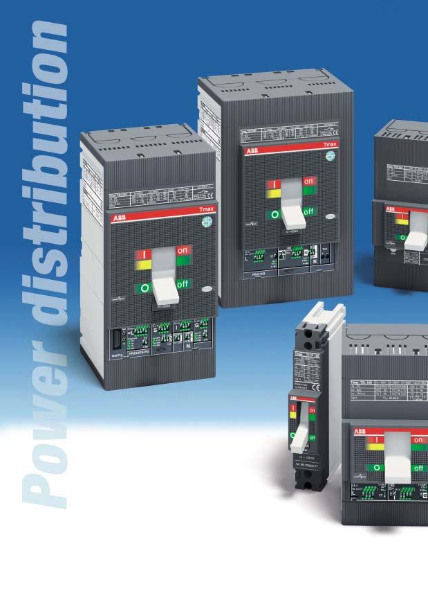
27 The ranges Index Tmax circuit-breakers for power distribution Electrical characteristics... 2/4 General characteristics... 2/6 Thermomagnetic releases... 2/8 2 Electronic releases... 2/11 Tmax circuit-breakers for motor protection Electrical characteristics... 2/20 Protection against short-circuit... 2/22 Integrated protection: PR222MP... 2/24 Tmax circuit-breakers for applications up to 1000 V Electrical characteristics... 2/32 Switch-disconnectors Electrical characteristics... 2/36 ABB SACE 2/1
28

29 Circuit-breakers for power distribution Index Tmax circuit-breakers for power distribution Electrical characteristics... 2/4 General characteristics... 2/6 Thermomagnetic releases... 2/8 2 Electronic releases... 2/11 ABB SACE 2/3
30 Circuit-breakers for power distribution Electrical characteristics 2 Tmax T1 1P Tmax T1 Rated uninterrupted current, Iu [A] [A] No. Poles [No.] 1 3/4 Rated service voltage, Ue (AC) Hz [V] (DC) [V] Rated impulse withstand voltage, Uimp [kv] 8 8 Rated insulation voltage, Ui [V] Test voltage at industrial frequency for 1 min. [V] Rated ultimate short-circuit breaking capacity, Icu B B C N (AC) Hz 220/230 V [ka] 25 ( * ) (AC) Hz 380/415 V [ka] (AC) Hz 440 V [ka] (AC) Hz 500 V [ka] (AC) Hz 690 V [ka] (DC) 250 V - 2 poles in series [ka] 25 (at 125 V) (DC) 250 V - 3 poles in series [ka] (DC) 500 V - 2 poles in series [ka] (DC) 500 V - 3 poles in series [ka] (DC) 750 V - 3 poles in series [ka] Rated service short-circuit breaking capacity, Ics (AC) Hz 220/230 V [%Icu] 75% 100% 75% 75% (AC) Hz 380/415 V [%Icu] 100% 100% 50% (25 ka) (AC) Hz 440 V [%Icu] 100% 75% 50% (AC) Hz 500 V [%Icu] 100% 75% 50% (AC) Hz 690 V [%Icu] 100% 75% 50% Rated short-circuit making capacity, Icm (AC) Hz 220/230 V [ka] (AC) Hz 380/415 V [ka] (AC) Hz 440 V [ka] (AC) Hz 500 V [ka] (AC) Hz 690 V [ka] Opening time (415 V) [ms] Category of utilisation (EN ) A A Isolation behaviour Reference standard IEC IEC Releases: thermomagnetic T fixed, M fixed TMF T adjustable, M fixed TMD T adjustable, M adjustable (5 10 x In) TMA T adjustable, M fixed (3 x In) TMG T adjustable, M adjustable (2.5 5 x In) TMG magnetic only MA electronic PR221DS-LS/I PR221DS-I PR222DS/P-LSI PR222DS/P-LSIG PR222DS/PD-LSI PR222DS/PD-LSIG PR222MP Interchangeability Versions F F Terminals fixed FC Cu FC Cu-EF-FC CuAl -HR plug-in withdrawable Fixing on DIN rail DIN EN Mechanical life [No. operations] [No. hourly operations] Electrical 415 V AC [No. operations] [No. hourly operations] Basic dimensions - fixed version L [mm] 25.4 (1 pole) 76 4 poles L [mm] 102 D [mm] H [mm] Weight fixed 3/4 poles [kg] 0.4 (1 pole) 0.9/1.2 plug-in 3/4 poles [kg] withdrawable 3/4 poles [kg] TERMINAL CAPTION F = Front 2/4 EF = Front extended ES = Front extended spread FC Cu FC CuAl = Front for copper cables = Front for CuAl cables R = Rear orientated HR = Rear in horizontal flat bar VR = Rear in vertical flat bar MC = Multicable ABB SACE
31 Tmax T2 Tmax T3 Tmax T4 Tmax T / /630 3/4 3/4 3/4 3/ N S H L N S N S H L V N S H L V % 100% 100% 100% 75% 50% 100% 100% 100% 100% 100% 100% 100% 100% 100% 100% 100% 100% 100% 75% (70 ka) 75% 50% (27 ka) 100% 100% 100% 100% 100% 100% 100% 100% 100% 100% 100% 100% 100% 75% 75% 50% 100% 100% 100% 100% 100% 100% 100% 100% 100% 100% 100% 100% 100% 75% 75% 50% 100% 100% 100% 100% 100% 100% 100% 100% 100% (1) 100% (2) 100% 100% 100% 75% 75% 50% 100% 100% 100% 100% 100% 100% 100% 100% (1) 100% (2) 100% (2) A A A A (630 A) - B (400 A) (3) IEC IEC IEC IEC (up to 50 A) (MF up to In 12.5 A) F-P F-P F-P-W F-P-W F-FC Cu-FC CuAl-EF-ES-R F-FC Cu-FC Cu Al-EF-ES-R F-FC Cu-FC CuAl-EF-ES-R-MC F-FC Cu-FC CuAl-EF-ES-R F-FC Cu-FC CuAl-EF-ES-R F-FC Cu-FC Cu Al-EF-ES-R EF-ES-HR-VR-FC Cu-FC CuAl EF-ES-HR-VR-FC Cu-FC CuAl EF-ES-HR-VR-FC Cu-FC CuAl EF-ES-HR-VR-FC Cu-FC CuAl DIN EN DIN EN (250 A) (320 A) 7000 (400 A) (630 A) / /3 2.35/ / / / / / / /6.9 F = Fixed circuit-breakers W = Withdrawable circuit-breakers (*) The breaking capacity for settings (1) 75% for T5 630 Notes: in the plug-in version of T2 P = Plug-in circuit-breakers In=16 A and In= 20 A is 16 ka (2) 50% for T5 630 and T3 the maximum setting ABB SACE (3) Icw = 5 ka is derated by 10% at 40 C 2/5
32 Circuit-breakers for power distribution General characteristics 2 General characteristics The new series of Tmax moulded-case circuit-breakers - complying with the IEC Standard - is divided into five basic sizes, with an application range from 1 A to 630 A and breaking capacities from 16 ka to 200 ka (at 380/415 V AC). Selection of the size allows the basic electrical characteristics to be identified simply and immediately, whereas selection of the overcurrent release is made according to the type of application required. Furthermore, for the first time ABB SACE has also developed a moulded-case circuit-breaker with a single-pole construction characteristic: T1B 1p. This is a 160 A rated uninterrupted current circuitbreaker, able to operate at service voltages up to 240 V AC and 125 V DC, complying with the IEC Standard. From the viewpoint of dimensions, the new T1B 1p is absolutely identical to the Tmax T1 size (same height H = 130 mm and same depth D = 70 mm), except for the width, typical of a single pole (L = 25.4 mm). It is therefore suitable for being installed in distribution switchboards by means of a back plate, even side by side with other circuit-breakers in the series. For protection of alternating current networks, the following are available: T1B 1p circuit-breaker, equipped with TMF thermomagnetic releases with fixed thermal and magnetic threshold (I 3 = 10 x In); T1, T2, T3 and T4 (up to 50 A) circuit-breakers equipped with TMD thermomagnetic releases with adjustable thermal threshold (I 1 = x In) and fixed magnetic threshold (I 3 = 10 x In); T3 and T5 circuit-breakers, fitted with TMG releases for generator protection with adjustable thermal threshold (I 1 = x In) and fixed magnetic threshold (I 3 = 3 x In) for T3 and adjustable magnetic threshold (I 3 = x In) for T5; T4 and T5 circuit-breakers with TMA thermomagnetic releases with adjustable thermal threshold (I 1 = x In) and adjustable magnetic threshold (I 3 = 5 10 x In). T2 with PR221DS electronic release; T4 and T5 with PR221DS, PR222DS/P and PR222DS/PD electronic releases. The field of application in alternating current of the Tmax series varies from 1 A to 630 A with voltages up to 690 V. The Tmax T1, T2, T3, T4 and T5 circuit-breakers equipped with TMD and TMA can also be used in direct current plants, with a range of application from 1 A to 630 A and a minimum operating voltage of 24 V DC. With two poles in series, T1, T2, T3 can be used with rated voltages of 250 V and T4, T5 with 500 V with breaking capacities up to 100 ka, whereas with 3 poles in series 500 V for T1, T2, T3 and 750 V for T4, T5 can be reached with breaking capacities still up to 100 ka for T1, T2, T3 and 70 ka for T4, T5. Interchangeability The Tmax T4 and T5 circuitbreakers can be equipped either with TMD, TMG or TMA thermomagnetic releases, MA magnetic only releases or PR221DS, PR222DS/P, PR222DS/PD and PR222MP electronic releases. Thanks to their simplicity of assembly, the end customer can, in fact, change the type of release extremely rapidly, according to Releases TMD TMA TMG Circuit-breakers In [A] T4 250 T4 320 T5 400 T5 630 = complete circuit-breaker already coded = circuit-breaker to be assembled (separate codes of the circuit-breaker part plus release) 2/6 ABB SACE
33 Application range of alternating and direct current circuit-breakers Release Range [A] AC T1 1p 160 TMF T1 160 TMD T2 160 TMD 1,6 160 MF/MA PR221DS T3 250 TMG TMD MA T4 250/320 TMD TMA MA PR221DS PR222DS/P PR222DS/PD T5 400/630 TMG TMA PR221DS PR222DS/P PR222DS/PD The three-pole T2, T3 and T4 circuit-breakers can also be fitted with MA adjustable magnetic only releases, both for applications in alternating current and in direct current, in particular for motor protection (see page 2/19 and following). 2 DC T1 1p 160 TMF T1 160 TMD T2 160 TMD 1,6 160 MF/MA T3 250 TMG TMD MA T4 250/320 TMD TMA MA T5 400/630 TMG TMA TMF = thermomagnetic release with fixed thermal and magnetic threshold TMD = thermomagnetic release with adjustable thermal and fixed magnetic threshold TMA = thermomagnetic release with adjustable thermal and magnetic threshold TMG = thermomagnetic release for generator protection PR22_ = electronic releases their own requirements and needs: in this case, correct assembly is the customer s responsibility. Above all, this means into increased flexibility of use of the circuit-breakers with considerable savings in terms of costs thanks to better rationalisation of stock management. MA PR221DS-LS/I or I PR222DS/P-LSI or LSIG PR222DS/PD-LSI or LSIG PR222MP ABB SACE 2/7

34 Circuit-breakers for power distribution Thermomagnetic releases 2 Thermomagnetic releases The Tmax T1 1p, T1, T2, T3, T4 and T5 circuit-breakers can be fitted with thermomagnetic releases and are used in protection of alternating and direct current networks with a range of use from 1,6 A to 630 A. They allow the protection against overload with a thermal device (with fixed threshold for T1 1p and adjustable threshold for T1, T2, T3, T4 and T5) realised using the bimetal technique, and protection against short-circuit with a magnetic device (with fixed threshold for T1, T2 and T3 and T4 up to 50 A and adjustable threshold for T4 and T5). The four-pole circuit-breakers are always supplied with the neutral protected by the release and with protection of the neutral at 100% of the phase setting for settings up to 100 A. For higher settings, the version with protection of the neutral at 50% of the phase setting is also available. Furthermore, for Tmax T3 and T5, the TMG thermomagnetic releases for generator protection are available. For T3 the release has adjustable thermal threshold (I 1 = x In) and fixed magnetic threshold (I 3 = 3 x In), whereas for T5 the release has adjustable thermal threshold (I 1 = x In) and adjustable magnetic threshold (I 3 = x In). Thermomagnetic release TMD and TMG (for T3) Thermal threshold Adjustable from 0.7 to 1 x In 1SDC210314F0004 1SDC210313F0004 Thermal threshold Adjustable from 0.7 to 1 x In TMD = thermomagnetic release with adjustable thermal threshold (I 1 = 0,7 1 x In) and magnetic fixed threshold. TMG (for T3) = thermomagnetic release for generator protection with adjustable thermal threshold (I 1 = x In) and fixed magnetic threshold 2/8 ABB SACE
35 Thermomagnetic release TMF for T1B 1p TMF - T1 1p I 1 = In In [A] SDC210186F0004 I 3 = 10 x In I 3 [A] TMF = thermomagnetic release with fixed thermal and magnetic threshold. 2 TMD - T1 and T3 In [A] Neutral [A] - 100% I 1 =0.7 1 x In Neutral [A] - 50% T T3 250 I 3 [A] Neutral [A] - 100% I 3 = 10 x In Neutral [A] - 50% TMD - T2 I 1 =0.7 1 x In I 3 = 10 x In TMG - T3 I 1 =0.7 1 x In In [A] Neutral [A] - 100% Neutral [A] - 50% I 3 [A] Neutral [A] - 100% Neutral [A] - 50% In [A] Neutral [A] - 100% I 3 [A] I 3 = 3 x In Neutral [A] - 100% Notes: In identifies the setting current for protection of the phases (L1, L2 and L3) and of the neutral. The TMD and TMA thermomagnetic releases have the thermal element with adjustable threshold I 1 = x In. The value of the thermal element adjustment which is obtained by acting on the special selector, is intended at 40 C. The magnetic element has fixed trip threshold with ± 20% tolerance according to what is indicated by the IEC (pos ) Standard. The trip thresholds of the magnetic protection I 3 are a function of the setting used both by the phase and neutral protection. ABB SACE 2/9

36 Circuit-breakers for power distribution Thermomagnetic releases Thermomagnetic release TMA and TMG (for T5) TMA TMG 2 Magnetic threshold Adjustable Thermal threshold Adjustable from 0.7 to 1 x In 1SDC210315F0004 TMA = thermomagnetic release with adjustable thermal threshold (I 1 = x In) and adjustable magnetic threshold (I 3 = 5 10 x In) TMG (for T5) = thermomagnetic release for generator protection with adjustable thermal threshold (I 1 = x In) and adjustable magnetic threshold (I 3 = x In) TMD/TMA - T4 I 1 = x In I 3 = 10 x In I 3 = 5 10 x In In [A] Neutral [A] - 100% Neutral [A] - 50% I 3 = 10 x In [A] I 3 = x In [A] Neutral [A] - 100% Neutral [A] - 50% TMA - T5 I 1 = x In I 3 = 5 10 x In TMG - T5 I 1 = x In In [A] Neutral [A] - 100% Neutral [A] - 50% I 3 [A] Neutral [A] - 100% Neutral [A] - 50% In [A] Neutral [A] - 100% I 3 [A] I 3 = x In Neutral [A] - 100% Notes: In identifies the setting current for protection of the phases (L1, L2 and L3) and of the neutral. The TMA and TMG thermomagnetic releases which equip the Tmax T4 and T5 circuit-breakers have the thermal element with adjustable threshold I 1 = x In. The set current value which is obtained using the special selector is intended at 40 C. The magnetic element has adjustable trip threshold (I 3 = 5 10 x In for TMA and I 3 = x In for TMG) with a tolerance of ± 20% according to what is indicated in the Norma IEC (pos ) Standard. 2/10 ABB SACE
 Medium time before failure (MTBF) The Tmax T2, T4 and T5 circuit-breakers for uses in alternating current")
37 Circuit-breakers for power distribution Electronic releases General characteristics Characteristics of the electronic releases - PR221DS, PR222DS/P and PR222DS/PD Operating temperature -25 C +70 C Relative humidity 90% Operating frequency Hz Electromagnetic compatibility (LF and HF) Medium time before failure (MTBF) The Tmax T2, T4 and T5 circuit-breakers for uses in alternating current can be equipped with PR221DS, PR222DS/P and PR222DS/PD overcurrent releases constructed using electronic technology. This allows protection functions to be obtained which guarantee great reliability, trip precision and immunity to electromagnetic components in compliance with the standards on the matter. The power supply required for correct operation is supplied directly by the release current transformers and tripping is always guaranteed, even under single-phase load conditions and in correspondence with the minimum setting. IEC Annex F 15 years (at 45 C) The protection releases are made up of the current transformers (three or four depending on the number of conductors to be protected), the SACE PR221DS, PR222DS/P or PR222DS/PD protection unit and of a trip coil with demagnetisation which acts directly on the circuit-breaker operating mechanism unit and is mounted in the right-hand slot of the circuit-breaker for Tmax T2 or is already housed in the release box for Tmax T4 and T5. The current transformers are housed inside the release box and supply the energy required for correct operation of the protection and the signal needed to detect the current. They are available with primary rated current as indicated in the table. When the protection trips, the circuit-breaker opens by means of the trip coil, which changes over a contact (AUX-SA, supplied on request) to signal release tripped. Signalling reset is of mechanical type and takes place with resetting of the circuit-breaker operating lever. The test of the trip coil can be carried out by means of the SACE TT1 test device. Positive outcome of the test coincides with circuit-breaker opening. 2 Current transformers In [A] PR221DS T2 T4 T5 L S I PR222DS/P or PR222DS/PD T4 T5 L S I * G * For T ABB SACE 2/11
38 Circuit-breakers for power distribution Electronic releases 2 PR221DS The PR221DS release, available for T2,T4 and T5, provides protection functions against overload L and short-circuit S/I (version PR221DS-LS/I): with this version, you can choose between protection S or I moving the dip-switch. Alternatively, the version with only the function of protection against instantaneous short-circuit I is available (version PR221DS-I, also see page 2/23). The wide range of settings makes this release particularly suitable in all distribution applications where reliability and trip precision are required and where only protection against short-circuit (I 3 = 1 10 x In) is needed, this obtained using the PR221DS release in version I. The PR221DS release for Tmax T2 has some differences compared with the one which can be used with T4 and T5. With Tmax T2, the release is not interchangeable, protection against overload L can be set manually at I 1 = x In with 16 thresholds by means of a dip switch on the front of the circuit-breaker, and it is possible to select between 2 trip curves 3s at 6 x I 1 and 6s at 6 x I 1. On the other hand, with Tmax T4 and T5, protection L can be set manually at I 1 = x In with 16 thresholds by means of a dip switch on the front of the circuit-breaker and it is possible select between 2 different Example of protection setting Given a T2 160 circuit-breaker with In= 100 A, set the protection L to I 1 =80 A in curve 3s, and S to 300 A in curve 0.25s: To obtain I 1 = 80 A, the dip switches in correspondence with 0.08 and 0.32 must be moved so that I 1 = In x ( ) = 100 x ( ) = 80 A. To select curve 3s, the dip switch in correspondence with t1 must be moved upwards. To obtain I 2 = 300 A, first of all, the dip must be moved in correspondance of S protection, then the dip switches in correspondence with 1 and 2 must be moved so that I 2 = In x (1 + 2) = 100 x (1 + 2) = 300 A. To select curve 0,25s, the dip switch in correspondence with t2 must be moved downwards. trip curves 3s at 6 x I 1 and 12s at 6 x I 1. The protection functions against delayed short-circuit S or, alternatively, instantaneous I are the same both for the PR221DS of Tmax T2 and for T4 and T5. PR221DS-LS/I Protection S Against short-circuit with delayed trip Protection L Against overload Dip-switches for setting the neutral (only for T4 and T5) Socket for TT1 test unit 1SDC210187F0004 Protection I Against short-circuit with instantaneous trip 2/12 ABB SACE
39 The protection function against short-circuit with delayed trip S, with inverse short time delay with inverse time characteristic (I 2 t= const) can be set, I 2 = x In with15 thresholds, and the possibility of excluding the protection, which can be set by means of the dip switches on the front of the circuitbreaker. The protection time delay can be selected by adjusting the dip switches on one of the two available curves (0.1s at 8 x In, 0.25s at 8 x In). The protection function against instantaneous short-circuit I can be adjusted to I 3 = 1 10 x In with 15 thresholds and the possibility of excluding the protection, which can be set by means of the specific dip switch. There is a single adjustment for the phases and the neutral. However, for these it can be decided whether to request the protection threshold of the functions at % of that of the phases for Tmax T2 (In = 100 A), whereas for T4 and T5 it is possible to select the protection threshold OFF, 50% or 100% directly from the front of the release by means of the specific dip switch. The trip coil is always supplied with the PR221DS release for Tmax T2 and is housed in the righthand slot of the circuit-breaker. A kit of auxiliary contacts, specifically for electronic T2, is available when ordering, which includes the following: 1 contact for signalling electronic release trip 1 contact for signalling open/closed 1 contact for signalling release trip. On the other hand, for Tmax T4 and T5, the trip coil is housed inside the electronic release and therefore, since the right slot of the circuit-breaker is not occupied, the auxiliary contacts available can be used. The auxiliary contacts AUX-SA to signal release trip can always be used (see page 3/18). 2 PR221DS - Protection functions and parameterisations Protection functions Trip threshold Trip curves (1) NOT EXCLUDABLE Against overload with long inverse time delay trip and trip characteristic according to an inverse time curve (I 2 t=constant) I 1 = x In Release between x I 1 (IEC ) at 6 x I 1 at 6 x I 1 at 6 x I 1 t 1 = 3s t 1 = 6s t 1 = 12s only for T2 only for T4, T5 Tolerance: ± 10% up to 6 x In; ± 20% above 6 x In EXCLUDABLE Against short-circuit with inverse short time delay trip and trip characteristic with inverse time (I 2 t=constant) (selectable as an alternative to protection function I) I 2 = 1-1, , ,5-4,5-5,5-6, , , x In Tolerance: ± 10% (T4-T5) ± 10% up to 2 x In (T2) ± 20% above 2 x In (T2) I 3 = 1-1, , ,5-4,5-5,5-6, , , x In Tolerance: ± 10% (T4-T5) ± 20% (T2) a 8 x In a 8 x In t 2 = 0,1s t 2 = 0,25s Tolerance: ± 10% up to 6 x In (T4-T5) ± 20% above 6 x In (T4-T5) ± 20% (T2) EXCLUDABLE Against short-circuit with instantaneous trip (selectable as an alternative to protection function S) istantaneous 25ms (1) These tolerances hold in the following conditions: self-powered relay at full power and/or auxiliary supply; two or three-phase power supply. peak factor peak = 2 (L and S with current 3 In; I) ( ) rms ABB SACE 2/13
40 Circuit-breakers for power distribution Electronic releases PR222DS/P 2 The PR222DS/P release, available for T4 and T5, has protection functions against overload L, delayed S and instantaneous I short-circuit (version PR222DS/P-LSI) and, alternatively, as well as the functions L, S, I, also has protection against earth fault G (version PR222DS/P-LSIG). The wide range of adjustments makes this release particularly suitable in all distribution applications where reliability and trip precision are required. Function L, which cannot be excluded, can be set manually to I 1 = x In with 32 thresholds which can be set by means of the dip switches on the front of the release, or electronically by means of the SACE PR010T test and configuration unit which can be set between I 1 = x In with 61 thresholds (steps of 0.01 x In). Furthermore, it is possible to select among four different trip curves: 3s at 6 x I 1, 6s at 6 x I 1, 9s at 6 x I 1, 12s at 6 x In for T4 In = 320 A and T5 In = 630 A and 18s at 6 x I 1 for all the other settings. Otherwise it is also possible to set the trip time to 6 x I 1 electronically between 3 and 18s with 31 thresholds (step of 0.5s), except for T4 In= 320 A and T5 In= 630 A, for which the maximum value is 12s. The function of protection against short-circuit with delayed trip S, with inverse short delay with characteristic with inverse time (I 2 t = cost) or with definite time, can be set to I 2 = x In with 15 thresholds and the possibility of excluding the protection, which can be set by means of the dip switches on the front of the circuit-breaker, or with the SACE PR010T I 2 = x In with 95 thresholds (steps of 0.1). The time delay of the protection can be selected either manually by adjusting the dip switch to one of the four curves available (with delay of 0.05s at 8 x In, 0.1s at 8 x In, 0.25s at 8 x In or 0.5s at 8 x In) or electronically by means of PR010T between 0.05 and 0.5s at 8 x In with 46 thresholds (steps of 0.01s). The function of protection against instantaneous shortcircuit I is adjustable to I 3 (1) = x In with 15 thresholds and the possibility of excluding the protection, can be set by means of dip switches, or with the SACE PR010T at I 3 (1) = x In with 86 thresholds (steps of 0.1 x In). The function of protection against earth fault G is adjustable either manually, by means of dip switches, to I 4 = x In with 7 thresholds and the possibility of excluding the protection, or electronically by means of the SACE PR010T to I 4 = x In with 81 thresholds (steps of 0.01 x In). It is also possible to select among four different trip curves: 0.1s at 3.15 x I 4, 0.2s at 2.25 x I 4, 0.4s at 1.6 x I 4 and 0.8s at 1.10 x I 4, or to set the trip time electronically between 0.1 and 0.8s with 71 thresholds (steps of 0.01s). There is a single setting for the phases and neutral, for which one can decide whether to set the threshold of the protection functions to OFF, to 50% or to100% that of the phases by means of two special dip switches on the front of the circuit-breaker. Furthermore, on the front of the PR222DS/P (or PD) releases, signalling of pre-alarm and alarm of protection L is available. The pre-alarm threshold value (cannot be excluded or modified by the user) is equal to 0.9 x I 1. It is also possible to transmit remotely the alarm of protection L, simply connecting connector X3 to the dedicated contact. (1) For T4 In = 320 A and T5 In = 630 A I 3 max = 10 x In 2/14 ABB SACE
41 PR222DS/PD Apart from the protection functions against overload L, delayed S and instantaneous I short-circuit (version PR222DS/ PD-LSI) or, alternatively, plus the Communication functions PR222DS/P PR222DS/PD Protocol Modbus RTU standard Physical medium EIA RS485 Speed (maximum) 19200bps Measurement functions Phase currents (1) Neutral (1) Earth (1) Signalling functions L pre-alarm and alarm LED L alarm output contact (2) Data available State of the circuit-breaker (open, closed) Mode (local, remote) Protection parameters set (1) Alarms Protections: L, S, I, G (1) Release control for failed fault (1) Maintenance Total number of operations Total number of trips Number of trip tests Number of manual operations Number of trips for each individual protection function Record of last trip data Commands Circuit-breaker opening/closing (with motor operator) Alarm reset Circuit-breaker reset (with motor operator) Setting the protection curves and thresholds (1) Safety function Automatic opening in the case of failed release for fault (with motor operator) Events Changes in circuit-breaker state, in the protections and all the alarams (1) With PR010/T unit (2) Typical contact: MOS photo Vmax: 48 V DC/30 V AC Imax: 50 ma DC/35 ma AC Auxiliary power supply - Electrical characteristics PR222DS/PD Auxiliary power supply (galvanically insulated) 24 V DC ± 20% Maximum ripple 5% Inrush 24 V Rated 24 V Rated 24 V 1 A for 30 ms 100 ma 2,5 W extra protection against earth fault G (version PR222DS/PD- LSIG), the PR222DS/PD release, available for T4 and T5, also has the dialogue unit integrated with Modbus RTU protocol. The Modbus RTU protocol has been known and used worldwide for many years and is now a market standard thanks to its simplicity of installation, configuration and to its integration in the various different supervision, control and automation systems, as well as good level performances. The PR222/PD releases allow the Tmax T4 and T5 circuitbreakers to be integrated in a communication network based on the Modbus RTU protocol. Modbus RTU provides a Master-Slave system architecture where a Master (PLC, PC ) cyclically interrogates several Slaves (field devices). The devices use the EIA RS485 standard as the physical means for data transmission at a maximum transmission speed of bit/sec. Again for this release, the power supply needed for correct operation of the protection functions is supplied directly by the current transformers of the release, and tripping is always guaranteed, even under conditions of single-phase load and in correspondence with the minimum setting. Nevertheless, communication is only possible with an auxiliary power supply of 24 V DC. The PR222DS/PD release, with integrated communication and control functions, allows a wide range of information to be acquired and transmitted remotely, to carry out opening and closing commands thanks to shunt opening and closing releases installed on board the circuitbreaker, to store the configuration parameters and those for programming the unit itself like the current thresholds of the protection functions and the protection curves. All the information can be consulted both locally, directly on the front of the circuit-breaker with the front display unit FDU, and remotely by means of supervision and control systems. The PR222DS/PD releases can be associated with the AUX-E auxiliary contacts in electronic version, to know the state of the circuit-breaker (open/closed), and with AUX-E plus MOE-E motor operator (the AUX-E are compulsory when MOE-E is to be used) to remotely control circuit-breaker opening and closing as well (also see page 3/17 and following). If the circuit-breaker fitted with the PR222DS/PD release is inserted in a supervision system, during the test phases with the PR010/T unit, communication is automatically abandoned and starts again on completion of this operation. Communication towards the display unit FDU is also available, which can also take place with self-supply starting from 0.35 x In present at least on one phase. The details of the functions available are indicated in the diagram. 2 ABB SACE 2/15

42 Circuit-breakers for power distribution Electronic releases PR222DS/P Protection S Against short-circuit with delayed trip Protection I Against short-circuit with instantaneous trip 2 Protection L Against overload Socket for test SACE TT1 test unit Socket for connection of SACE PR010/T test unit Protection G Against earth fault Dip-switches for setting the neutral 1SDC210188F0004 Selection for electronic or manual setting PR222DS/PD Protection S Against short-circuit with delayed trip Protection L Against overload Socket for test SACE TT1 test unit Socket for connection of SACE PR010/T test unit Protection I Against short-circuit with instantaneous trip Protection G Against earth fault Dip-switches for setting the neutral Selection for local or remote setting 1SDC210189F0004 Selection for electronic or manual setting 2/16 ABB SACE
43 PR222DS/P and PR222DS/PD - Protection functions and parameterisations Protection functions Trip threshold Trip curves (1) NOT EXCLUDABLE Against overload with long inverse time delay trip and trip characteristic according to an inverse time curve (I 2 t= constant) Manual setting I 1 = x In Manual setting at 6 x I 1 at 6 x I 1 at 6 x I 1 at 6 x I 1 t 1 = 3s t 1 = 6s t 1 = 9s t 1 = 18s (2) EXCLUDABLE Against short-circuit with inverse short time delay trip and trip characteristic with inverse time (I 2 t= constant) or definite time I 2 t=const ON Electronic setting I 1 = x In (step 0.01 x In) Release between x I 1 (IEC ) Manual setting I 2 = x In Electronic setting I 2 = x In (step 0.1 x In) Tolerance: ± 10% Electronic setting at 6 x I 1 t 1 = 3 18s (step 0,5s) (2) Tolerance: ± 10% Manual setting at 8 x In at 8 x In at 8 x In at 8 x In t 2 = 0.05s t 2 = 0.1s t 2 = 0.25s t 2 = 0.5s Electronic setting at 8 x In t 2 = s (step 0.01s) Tolerance: ± 10% (4) 2 Manual setting I 2 = x In Manual setting t 2 = 0.05s t 2 = 0.1s t 2 = 0.25s t 2 = 0.5s I 2 t=const OFF Electronic setting I 2 = x In (step 0.1 x In) Tolerance: ± 10% Electronic setting t 2 = s (step 0.01s) Tolerance: ± 10% (4) EXCLUDABLE Against short-circuit with instantaneous trip Manual setting I 3 = x In (3) Electronic setting I 3 = x In (step 0.1 x In) (3) Tolerance: ± 10% istantaneous 25 ms EXCLUDABLE Against earth fault with inverse short time delay trip and trip characteristic according to an inverse time curve (I 2 t= constant) Manual setting I 4 = x In Electronic setting I 4 = x In (step 0.01 x In) Tolerance: ± 10% Manual setting up to up to up to up to 3.15 x I x I x I x I 4 t 4 = 0.1s t 4 = 0.2s t 4 = 0.4s t 4 = 0.8s Electronic setting t 4 = x In (step 0.01s) Tolerance: ± 20% (1) These tolerances hold in the following conditions: self-powered relay at full power and/or auxiliary supply; two or three-phase power supply sinusoidal wave forms with peak factor 1.41 peak factor peak = 2 (L 3 In; S, I, G) ( rms ) (2) for T4 In = 320 A and T5 In = 630 A t 1 = 12s (3) for T4 In = 320 A and T5 In = 630 A I 3 max = 10 x In (4) tolerance: ± 10 ms up to t 2 = 0.1s ABB SACE 2/17
44

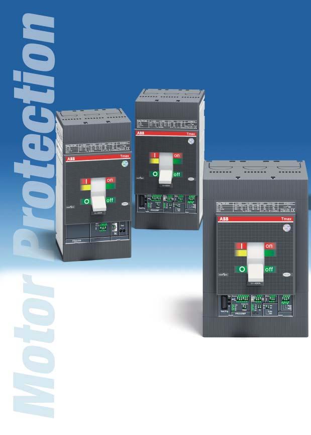
45 Circuit-breakers for motor protection Index Tmax circuit-breakers for motor protection Electrical characteristics... 2/20 Protection against short-circuit... 2/22 Integrated protection: PR222MP... 2/24 2 ABB SACE 2/19
46 Circuit-breakers for motor protection Electrical characteristics 2 Tmax T2 Rated uninterrupted current, Iu [A] 160 Rated service current, In [A] Poles [No.] 3 Rated service voltage, Ue (AC) Hz [V] 690 (DC) [V] 500 Rated impulse withstand voltage, Uimp [kv] 8 Rated insulation voltage, Ui [V] 800 Test voltage at industrial frequency for 1 min. [V] 3000 Rated ultimate short-circuit breaking capacity, Icu N S H L (AC) Hz 220/230 V [ka] (AC) Hz 380/415 V [ka] (AC) Hz 440 V [ka] (AC) Hz 500 V [ka] (AC) Hz 690 V [ka] Rated short-circuit service breaking capacity, Ics [%Icu] (AC) Hz 220/230 V [%Icu] 100% 100% 100% 100% (AC) Hz 380/415 V [%Icu] 100% 100% 100% 75% (70 ka) (AC) Hz 440 V [%Icu] 100% 100% 100% 75% (AC) Hz 500 V [%Icu] 100% 100% 100% 75% (AC) Hz 690 V [%Icu] 100% 100% 100% 75% Rated short-circuit making capacity, Icm [ka] (AC) Hz 220/230 V [ka] (AC) Hz 380/415 V [ka] (AC) Hz 440 V [ka] (AC) Hz 500 V [ka] (AC) Hz 690 V [ka] Opening time (415 V) [ms] Category of use (EN ) Isolation behaviour A Reference Standard IEC Protection against short-circuit Magnetic only release MA (MF up to In 12.5 A) Electronic release PR221DS-I Integrated protection (IEC ) Electronic release PR222MP Interchangeability Versions F-P Terminals fixed F - FC Cu - FC CuAl - EF - ES - R - FC CuAl plug-in F - FC Cu - FC CuAl - EF - ES - R - FC CuAl withdrawable Fixing on DIN rail DIN EN Mechanical life [No. operations] [No.hourly operations] 240 Electrical 415 V AC [No. operations] 8000 [No.hourly operations] 120 Basic fixed version dimensions L [mm] 90 D [mm] 70 H [mm] 130 Weight fixed [kg] 1.1 plug-in [kg] 1.5 withdrawable [kg] TERMINAL CAPTION F = Front EF = Front extended ES = Front extended spread FC Cu = Front for copper cables R = Rear orientated FC CuAl = Front for CuAl cables MC = Multicable HR = Rear in horizontal flat bar VR = Rear in vertical flat bar (*) Icw = 5 ka (1) 75% for T5 630 (2) 50% for T /20 ABB SACE
47 Tmax T3 Tmax T4 Tmax T , , , 400, N S N S H L V N S H L V % 50% 100% 100% 100% 100% 100% 100% 100% 100% 100% 100% 75% 50% (27 ka) 100% 100% 100% 100% 100% 100% 100% 100% 100% 100% 75% 50% 100% 100% 100% 100% 100% 100% 100% 100% 100% 100% 75% 50% 100% 100% 100% 100% 100% 100% 100% 100% 100% (1) 100% (2) 75% 50% 100% 100% 100% 100% 100% 100% 100% 100% (1) 100% (2) 100% (2) A A B (400 A) (*) - A (630 A) IEC IEC IEC F-P F-P-W F-P-W F - FC Cu - FC CuAl - EF - F - FC Cu - FC CuAl - EF - ES - R - MC F - FC Cu - FC CuAl - EF - ES - R ES - R - FC CuAl F - FC Cu - FC CuAl - EF - EF - ES - FC Cu - FC CuAl - HR - VR EF - ES - FC Cu - FC CuAl - HR - VR ES - R - FC CuAl EF - ES - FC Cu - FC CuAl - HR - VR EF - ES - FC Cu - FC CuAl - HR - VR DIN EN ABB SACE 2/21

48 Circuit-breakers for motor protection Protection against short-circuit General characteristics 2 Circuit-breaker with magnetic only release Contactor Thermal relay Motor Protection against short-circuit Starting, switching and protection of three-phase asynchronous motors are basic operations for their correct use. ABB SACE proposes two different solutions for this type of application: a traditional system, which foresees a circuit-breaker for protection against short-circuit, a thermal relay for protection against overload and missing or unbalanced phase and a contactor for motor switching; a system of integrated protection thanks to the PR222MP release, which ensures both protection against short-circuit, and against overload, as well as that against missing or unbalanced phase and that against the rotor block. All this must necessarily take into account the problems which arise at the moment of starting. In particular, when selecting these devices, different factors must be taken into consideration, such as: the motor power the diagram and type of starting the type of motor: with cage rotor or with wound rotor the fault current at the point of the network where the motor is installed. PTC Integrated protection Circuitbreaker with electronic release PR222MP PR212/CI Contactor Motor Protection against short-circuit Magnetic only and electronic overcurrent releases With the new series of Tmax moulded-case circuit-breakers, ABB SACE proposes a range up to 400 A, which implementing exclusively the protection against short-circuit, is suitable for use inside protected starters of traditional type. The Tmax T2,T3 and T4 circuit-breakers in the three-pole version with fixed magnetic only release (only for T2, I 3 = 13 x In up to In = 12.5 A) or adjustable between 6 and 12 times the rated service current for T2 and T3, and between 6 and 14 times for T4, stand out for their compactness and exceptional performances in terms of breaking capacity and limitation of the specific let-through energy. Furthermore, thanks to the great flexibility given by the wide range of magnetic threshold settings, they allow optimal motor protection. 1SDC210190F0004 2/22 ABB SACE
49 MF - Fixed magnetic only releases Tmax T2 In [A] I 3 = 13 x In I 3 = 13 x In Note The magnetic only releases which equip the Tmax T2 in three-pole version circuit-breaker have a trip threshold I 3 fixed at 13 x In, according to what is indicated in the table. MA - Adjustable magnetic only releases 2 Tmax T2-T3-T4 I 3 = 6 12 x In I 3 = 6 14 x In In [A] Tmax T2 Tmax T3 Tmax T4 Tmax T2, T3 I 3 = 6 12 x In Tmax T4 I 3 = 6 14 x In Note The magnetic only releases which equip the Tmax T2 and T3 three-pole version circuit-breakers have a trip thresould I 3 which can be adjusted from 6 to 12 x In for T2 and T3 and from 6 to14 x In for T4, according to what is indicated in the table. 12 or 14 They can be used in a wide range of start-ups, from 0.37 kw to 45 kw for T2 and up to 250 kw for T5 (at 400 V). Finally, T2, T4 and T5 with different levels of breaking capacity in the three-pole and fourpole versions, fitted with the PR221DS-I electronic release, allow selection of the most suit- Characteristics In [A] Tmax T2 Tmax T4 Tmax T5 I 3 [A] able trip value for any type of motor, thanks to the adjustment of the protection against shortcircuit from 1 to 10 times the rated current. PR221DS-I - Protection functions and parameterisation Protection function Against short-circuit with adjustable instantaneous trip Trip threshold I 3 = x In Tolerance ± 20% (T2) ± 10% (T4-T5) ABB SACE 2/23
 Medium time before failure (MTBF) PR222MP electronic overcurrent releases In the three-pole version, the Tmax T4 and T5")
50 Circuit-breakers for motor protection Integrated protection: PR222MP 2 Integrated protection Characteristics of the SACE PR222MP electronic release Operating temperature -25 C +70 C Relative humidity 90% Operating frequency Hz Electromagnetic compatibility (LF and HF) Medium time before failure (MTBF) PR222MP electronic overcurrent releases In the three-pole version, the Tmax T4 and T5 circuit-breakers are fitted with PR222MP electronic releases. This makes it possible to obtain functions which guarantee high trip precision, extreme reliability and immunity to variations in the external temperature. The PR222MP releases fully integrated on board the circuit-breaker guarantee complete protection of the motor. In fact, it is not necessary to provide the help of an external thermal relay for protection against overloads as, on the other hand, occurs with the standard solution. The PR222MP can be connected to a contactor for the basic pro- IEC Annex F 15 years (at 45 C) tection function (NORMAL mode) of the motor: the circuitbreaker can control contactor opening in the case of a fault (excluding short-circuit), by means of the SACE PR212/CI accessory control unit. In fact, a contactor has breaking capacities at high currents which are less efficient than the circuit-breaker, but a high number of possible operations consistently higher than those of the circuit-breaker (about ). The combination of the two devices therefore optimises motor protection and control. However, the PR222MP can also be connected directly to the motor (HEAVY mode). In this case, the circuit-breaker is called on to protect the plant in any case, without the help of the contactor: this solution is suggested for motors with a low number of operations. 1SDC210328F0004 PR222MP - Electronic overcurrent releases Tmax T4-T5 In [A] T4 250 N, S, L T5 400 N, S, L I 1 [A] x I 1 I 5 [A] I 3 [A] I 6 [A] 0.4 x I 1 2/24 ABB SACE
51 In any case, the PR010/T unit for testing the release and checking the protection functions, and the PR020/K signalling unit are available for the PR222MP release. The electronic releases are self-supplied and are made up of three current transformers, the PR222MP protection unit and a trip coil which acts directly on the circuit-breaker operating mechanism. The current transformers, housed inside the release box, supply the energy and the signal required for correct protection operation. Operation is guaranteed with a single-phase current equal to 20% of the rated current. The release is temperature-compensated and is sensitive to missing phase according to Table IV of the IEC Standards. The T4 and T5 circuit-breakers for motor protection are perfectly integrated with the new line of ABB contactors. The latter - defined as A-line - together with the line of thermal relays and ABB SACE moulded-case circuit-breakers, is the basis for the new generation of apparatus specially designed to guarantee a system of products which can be integrated according to the required applications. All this has the aim not only of continually improving the products, but above all of providing designers, installers and end users with the best solutions in terms of performances and reliability, combined with the simplicity of the system. The Tmax T4 and T5 circuit-breakers with PR222MP release and the A series of contactors are, in particular, an extraordinary solution in terms of compactness, sharing the same width and thereby saving space, assembly material, installation time and relative cabling operations. The combination of circuit-breaker-contactor allows an extremely compact protected starter to be made. 2 Typical operating characteristic of an asynchronous motor l 1 l 3 I 5 t 5 I 6 t 6 l e l a I p t a t p = function L trip current = function I trip current = function R trip current = function R trip time = function U trip current = function U trip time = rated service current of the motor = motor starting current = peak value of the sub-transient starting current = motor starting time = duration of the sub-transient starting phase m = typical motor starting curve c = example of trip curve of a motor protection circuit-breaker with electronic release The different curves of the functions, with numerous threshold and time settings, allow an overall trip curve to be drawn which is really close to the motor starting curve, thereby optimising its protection. ABB SACE 2/25
52 Circuit-breakers for motor protection Integrated protection: PR222MP 2 1SDC210330F0004 Protection functions Function L Function L protects the motor against overloads according to the indications and classes defined by the IEC Standard. The protection is based on a pre-defined model (ABB SACE international patent) which, by simulating the copper and iron over-temperatures inside the motor, allows precise safeguarding of the motor. The protection intervenes when the established over-temperature is reached. The trip time is fixed by selecting the trip class defined in the above-mentioned Standard. The function is temperature-compensated and sensitive to a missing/unbalanced phase according to the IEC Standard. In the case of an auxiliary power supply, the thermal memory function is guaranteed, which allows the release to continue to calculate the motor temperature even following an opening. Function L, which cannot be excluded, can be set manually to I 1 =0.4 1 x In with 60 thresholds which can be set by means of the dip-switches on the front of the release, or electronically by means of the SACE PR010T test and configuration unit. The starting class of the motor must then be selected, which determines the trip time for overload according to the IEC Table II Standards: class 10 A corresponds to a trip time t 1 = 4s, class 10 to t 1 = 8s, class 20 to t 1 = 16s and class 30 to t 1 = 24s at 7.2 x In. Setting this trip time can also be carried out electronically with the PR010T: the electronic steps are equal to 1s. Tripping of this protection leads to contactor opening (with the PR212/CI unit). Any anomaly of the contactor would make the circuit-breaker open, thanks to the BACK UP function. For protection L, there is then a pre-alarm and an alarm LED: the pre-alarm threshold value (cannot be either excluded or modified by the user) is equal to 0.9 x I 1 and the LED is permanently lit, whereas it flashes in case of alarm (I > 1.05s x I 1 ). 1SDC210333F0004 Function R: protection against rotor block Function R protects the motor against possible rotor block during operation. Protection R has the characteristic of protecting the motor in two different ways, according to whether the fault is present at start-up or whether it is present during normal service of an already active plant. In the former case, protection R is linked to protection L for time selection as well: in the presence of a fault during start-up, protection R is inhibited for a time equal to the time set with the trip class. Once this time is exceeded, protection R becomes active leading to a trip after a fixed set t 5 time. In the latter case, protection R is already active and the protection tripping time will be equal to t 5. The protection intervenes when at least one of the phase currents exceeds the established value and remains over that threshold for time t 5. Function R can be set manually I 5 = 3 10 x I 1 with 8 thresholds which can be set by means of the dip-switches on the front of the release, or with 70 thresholds by means of the SACE PR010T test and configuration unit (steps of 0.1 x I 1 ). The trip time t 5 can be set to 1, 4, 7 or 10 seconds by means of a dip-switch, or with steps of 0.5s by means of PR010T. Tripping of this protection leads to contactor opening (with the PR212/CI unit); any anomaly of the contactor would make the circuit-breaker open, thanks to the BACK UP function. 1SDC210335F0004 Function I: protection against short-circuit This protection function intervenes in the case of a short-circuit between phases. It is sufficient for just a single phase to exceed the set threshold to cause immediate opening of the circuit-breaker (protection cannot be excluded). The trip current can be adjusted up to 13 times the rated current of the release with 8 thresholds which can be set by means of a dip-switch or with 70 thresholds by means of the PR010T (steps of 0.1 x In). To prevent unwarranted trips during starting, the protection recognises whether the motor to be protected is in the starting phase or whether there is a short-circuit: this is to allow starting in completely safe conditions. Tripping of this protection makes the circuit-breaker open. 2/26 ABB SACE
53 1SDC210332F0004 Function U: protection against missing phase and/or unbalanced Function U can be used in those cases where a particularly precise control is needed regarding phase missing/unbalanced. This protection can be excluded and intervenes if the effective value of one or two currents drops below the level equal to 0.4 of the current I 1 set for protection L and remains there for longer than 4 seconds. This protection can be set electronically with the PR010T from 0.4 to 0.9 x I 1 with time adjustable between 1 and 10s (steps of 0.5s). Tripping of this protection leads to contactor opening (with the PR212/CI unit); any anomaly of the contactor would make the circuit-breaker open, thanks to the BACK UP function. Parameterisation of the PR222MP release Man/Elt: by means of a dip switch located on the front, the release can be provided for manual parameterisation (Man) of the thresholds and times acting directly on the dip switches located on the front of the release or with electronic parameterisation (Elt) by means of the PR010T. 2 Reset Mode AUTO/Man: this function (AUTO) allows the state of activation of the PR212/CI to be automatically reset following contactor trip for L function, after a fixed time of 15s. The AUTO reset is only possible when there is an auxiliary voltage. Setting the working modes Normal: the Normal mode foresees the use of a circuit-breaker and a contactor: this configuration makes intervention towards the contactor possible, through the PR212/CI unit, when the PR222MP considers this appropriate. Heavy: on the other hand, the heavy mode foresees the use of only the circuit-breaker and therefore the PR222MP sends the trip signal directly to the circuit-breaker. 1SDC210331F0004 BACK UP Function This protection is conceived to manage the possibility that an opening command sent to the contactor might not have a positive outcome, i.e. that the contactor does not intervene. In this case, after having waiting for the time defined using the dip switch k time (min = 80ms or max = 160ms), the PR222MP sends a trip signal to the circuit-breaker. Introducing a time delay between the command sent to the contactor and the back-up one is necessary to compensate the contactors actuation time. Setting the PTC protection PTC: this protection, by means of a PTC sensor inserted in the motor, controls the internal temperature. In case of overtemperature, the PR222MP will control opening of the contactor (when in Normal mode) or circuit-breaker (when in Heavy mode). 0/1: is a generic contact defined by the user and has nothing to do with the meaning of the PTC. ABB SACE 2/27

54 Circuit-breakers for motor protection Integrated protection: PR222MP PR222MP 2 Protection R Against rotor block Protection L Against motor overload Socket for connection of SACE PR010/T test unit Socket for SACE TT1 test unit Class Class of motor starting according to the IEC Standards Protection I Against short-circuit with instantaneous trip Protection U Against phase current unbalance or loss of phase Setting the work methods Man/Elt Release parametrisation methods 1SDC210195F0004 Selection between: - PTC (1) temperature sensor input - 0/1 generic input Setting the back-up time Setting the reset following trip - manual - automatic (1) A special input is available to connect a PTC temperature probe, inserted in the motor to be protected 2/28 ABB SACE
55 PR222MP - Protection functions and parameterisation Protection functions Trip threshold Trip curves (1) NOT EXCLUDABLE Against overload with long inverse time delay trip and trip characteristic according to an inverse time curve Manual setting I 1 = x In with step 0.01 x In Manual setting Trip classes: 10 A (IEC ) t 1 = s where t 1 is the trip time at 7.2 x I 1 cold, depending on the class selected Electronic setting I 1 = x In with step 0.01 x In Tolerance: ± 15% Electronic setting t 1 = 4 24s (step 1s) Tolerance: ± 15% EXCLUDABLE Against rotor block with delayed trip and trip characteristic with definite time Manual setting I 5 = OFF x I 1 Electronic setting I 5 = OFF x I 1 (step 0.1 x I 1 ) Tolerance: ± 15% Manual setting t 5 = s Electronic setting t 5 = 1 10s (step 0.5s) Tolerance: ± 10% 2 Against short-circuit with adjustable instantaneous trip Manual setting I 3 = x In NOT EXCLUDABLE Electronic setting I 3 = x In (step 0.1 x In) Tolerance: ± 15% EXCLUDABLE Against phase current unbalance or loss of phase with inverse long time delay trip and trip characteristic with definite time Manual setting I 6 = ON (0.4 x I 1 ) - OFF Electronic setting I 6 = x I 1 - OFF Tolerance: ± 15% Manual setting t 6 = 4s Electronic setting t 6 = 1 10s (step 0.5s) Tolerance: ± 10% (1) These tolerances hold in the following conditions: self-powered relay at full power and/or auxiliary supply; two or three-phase power supply. ABB SACE 2/29

56

57 Circuit-breakers for applications up to 1000 V Index Tmax circuit-breakers for applications up to 1000 V Electrical characteristics... 2/32 2 ABB SACE 2/31
58 Circuit-breakers for applications up to 1000 V Electrical characteristics The range of circuit-breakers for applications in direct current and in alternating current up to 1000 V also comes into the panorama of the Tmax proposal. The typical sectors of use are installations in mines, road or rail tunnels, traction and industrial applications in general. The circuit-breakers are available in the three-pole and four-pole version with TMD or TMA adjustable thermomagnetic releases for use in direct and alternating current, or in the three-pole version with PR221DS and PR222DS/P electronic releases for applications in alternating current. The dimensions of these circuit-breakers are the same as the standard ones. Furthermore, they can also be combined with all the accessories available for the Tmax series, except for the residual current release, and can be converted into plug-in or withdrawable version using the conversion kits and fixed parts of standard circuit-breakers. 2 Circuit-breakers with electronic release for applications at 1000 V in AC Tmax T4 Tmax T5 Rated uninterrupted current, Iu [A] , 630 Poles [No.] 3 3 Rated service voltage, Ue (AC) Hz [V] Rated impulse withstand voltage, Uimp [kv] 8 8 Rated insulation voltage, Ui [V] Test voltage at industrial frequency for 1 min. [V] Rated ultimate short-circuit breaking capacity, Icu L V L V (AC) Hz 1000 V [ka] Rated service short-circuit breaking capacity, Ics [%Icu] (AC) Hz 1000 V [ka] 100% 100% 75% 75% Rated short-circuit making capacity, Icm [ka] (AC) Hz 1000 V [ka] Category of utilisation (EN ) A B (400 A) (*) - A (630A) Isolation behaviour Reference Standard IEC IEC Electronic releases PR221DS-LS PR221DS-I PR222DS-LSI PR222DS-LSIG Interchangeability Versions F-P-W F-P-W Terminals fixed F-FCCu-FCCuAl-EF-ES-R-MC F-FCCu-FCCuAl-EF-ES-R plug-in FCCu-FCCuAl-EF-ES-HR-VR FCCu-FCCuAl-EF-ES-HR-VR withdrawable FCCu-FCCuAl-EF-ES-HR-VR FCCu-FCCuAl-EF-ES-HR-VR Mechanical life Basic dimensions - fixed version 3 poles L [mm] D [mm] H [mm] Weight fixed 3 poles plug-in 3 poles withdrawable 3 poles TERMINAL CAPTION F = Front EF = Front extended ES = Front extended spread FC Cu = Front for copper cables FC CuAl = Front for CuAl cables R = Rear orientated HR = Rear in horizontal flat bar VR = Rear in vertical flat bar MC = Multicable (*) Icw = 5 ka Electronic releases for applications up to 1000 V AC - PR221DS, PR222DS/PD and PR222DS/P In [A] T4 250 T5 400 T /32 ABB SACE
59 Circuit-breakers with thermomagnetic release for applications at 1000 V in AC/DC Tmax T4 Tmax T5 Rated uninterrupted current, Iu [A] , 630 No. Poles Nr. 4 4 Rated service voltage, Ue (AC) Hz [V] Rated impulse withstand voltage, Uimp [kv] 8 8 Rated insulation voltage, Ui [V] Test voltage at industrial frequency for 1 min. [V] Rated ultimate short-circuit breaking capacity, Icu V V (AC) Hz 1000 V [ka] (DC) 1000 V, 4 poles in series [ka] Rated service short-circuit breaking capacity, Ics [%Icu] (AC) Hz 1000 V [ka] 100% 75% Rated short-circuit making capacity, Icm [ka] (AC) Hz 1000 V [ka] Category of utilisation (EN ) A B (400 A) (*) - A (630A) Isolation behaviour Reference Standard IEC IEC Thermomagnetic releases TMD TMA Interchangeability Versions F-P-W F-P-W Terminali fixed F-FCCu-FCCuAl-EF-ES-MC F-FCCu-FCCuAl-EF-ES plug-in FCCu-FCCuAl-EF-ES-HR-VR FCCu-FCCuAl-EF-ES-HR-VR withdrawable FCCu-FCCuAl-EF-ES-HR-VR FCCu-FCCuAl-EF-ES-HR-VR Mechanical life Basic dimensions - fixed version 3 poles L [mm] poles L [mm] D [mm] H [mm] Weight fixed 3 poles plug-in 3 poles withdrawable 3 poles TERMINAL CAPTION F = Front EF = Front extended ES = Front extended spread FC Cu = Front for copper cables FC CuAl = Front for CuAl cables R = Rear orientated HR = Rear in horizontal flat bar VR = Rear in vertical flat bar MC = Multicable (*) Icw = 5 ka Thermomagnetic releases for applications at 1000 V in AC/DC - TMD and TMA In [A] I 1 = x In Neutral [A] - 100% T4 250 T5 400 T5 630 I 3 = 10 x In [A] I 3 = x In [A] I 3 = 10 x In I 3 = 5 10 x In ABB SACE 2/33
60

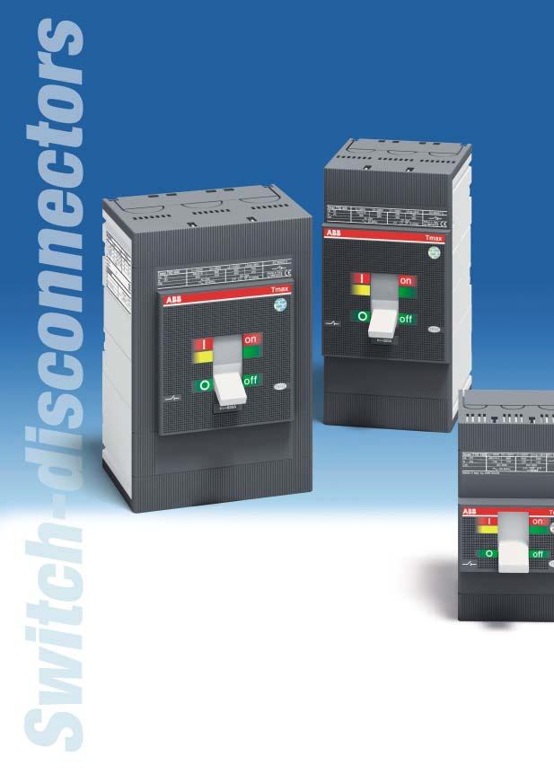
61 Switch-disconnectors Index Switch-disconnectors Electrical characteristics... 2/36 2 ABB SACE 2/35
62 Switch-disconnectors Electrical characteristics The Tmax switch-disconnectors derive from the corresponding circuit-breakers, of which they keep the overall dimensions, versions, fixing systems and the possibility of mounting accessories unchanged. This version only differs from the circuit-breakers in the absence of the protection releases. They are characterised by a rated voltage of 690 V in alternating current and 750 V in direct current. 2 Tmax T1D Conventional thermal current, Ith [A] 160 Rated service current in category AC23, Ie [A] 125 Poles [No.] 3/4 Rated service voltage, Ue (AC) Hz [V] 690 (DC) [V] 500 Rated impulse withstand voltage, Uimp [kv] 8 Rated insulation voltage, Ui [V] 800 Test voltage at industrial frequency for 1 minute [V] 3000 Rated short-circuit making capacity, Icm (min) switch-disconnector only [ka] 2.8 (max) with circuit-breaker on supply side [ka] 187 Rated short-time withstand current for 1s, Icw [ka] 2 Insulation behaviour Reference Standard IEC Versions Terminals F FCCu-EF-FCCuAl-HR Mechanical life [No. Operations] [No. Hourly Operations] 120 Basic dimensions, fixed 3 poles L [mm] 76 4 poles L [mm] 102 H [mm] 130 D [mm] 70 Weight fixed 3/4 poles [kg] 0.9/1.2 plug-in 3/4 poles [kg] withdrawable 3/4 poles [kg] Coordination between switch-disconnectors and circuit-breakers [380/415 V AC] T1 T2 T3 B C N N S H L N S Icu [ka] T1D T3D T4D 320 T5D 400 T5D 630 Applications They can be used as general circuit-breakers in sub-switchboards as switching and isolation parts for lines, busbars or groups of apparatus, or as bus-ties. They can be part of general isolation devices of groups of machines or of complexes for motor switching and protection. Isolation The main function carried out by this apparatus consists of isolation of the circuit they are inserted in. Once the contacts are open they are at a distance which prevents an arc from striking, in accordance with the prescriptions in the standards regarding isolation behaviour. The position of the operating lever corresponds definitely with that of the contacts (positive operation). 2/36 ABB SACE
63 Protection Each switch-disconnector must be protected on the supply side by a coordinated device which safeguards it against short-circuits. The coordination table below indicates the Tmax circuit-breaker which can carry out the protection function for each switch-disconnector. These are always pieces of apparatus of a size corresponding to or smaller than that of the switch disconnector. Tmax T3D Tmax T4D Tmax T5D / /630 3/4 3/4 3/ IEC IEC IEC F-P F-P-W F-P-W F-FCCuAl-FCCu-EF-ES-R F-FCCuAl-FCCu-EF-ES-R-MC-HR-VR F-FCCuAl-FCCu-EF-ES-R-HR-VR /3 2.35/ / / / / / /6.9 T4 T5 400 T5 630 N S H L V N S H L V N S H L V Making capacity The making capacity Icm is a performance of notable importance since a switch-disconnector must be able to withstand the dynamic, thermal and current stresses which can occur during closure without being destroyed, up to the short-circuit closing conditions. Withstand capacity in closed position This identifies the capacity to maintain the closed position for short-time overcurrents. It is a significant parameter which qualifies the performances of this apparatus. ABB SACE 2/37
64
65 Accessories Index Versions and types... 3/3 Connection terminals... 3/7 Service releases... 3/14 Electrical signals... 3/17 Remote control... 3/21 Operating mechanisms and locks... 3/24 Residual current releases... 3/29 3 Accessories for electronic releases... 3/33 Automatic transfer switch - ATS /36 Installation and test accessories; spare parts... 3/39 Compatibility - Internal accessories... 3/40 ABB SACE 3/1

66 Accessories The range of accessories of the Tmax series is characterised by the completeness of the solutions proposed together with flexibility and facility of use. 3 1SDC210321F0004 3/2 ABB SACE
, using the conversion Kits. This makes management of the product, its versions and stocks as a whole very flexible.")
67 Accessories Versions and types Starting from the fixed version with front terminals, the Tmax circuit-breakers can be converted into the various versions (plug-in for T2, T3, T4 and T5; withdrawable for T4 and T5), using the conversion Kits. This makes management of the product, its versions and stocks as a whole very flexible. In any case, it is always possible to request the circuit-breaker in the desired version completely preset in the factory, by ordering, on the same line, the fixed circuit-breaker and the conversion kit, to which must be added the fixed part. 1SDC210196F0004 Fixed The Tmax FIXED three-pole or four-pole version circuit-breakers foresee: circuit-breakers characterised by just two depths: 70 mm for Tmax T1, T2 and T3 and mm for Tmax T4 and T5 standard front in groups of circuit-breakers: 45 mm for Tmax T1, T2 and T3 and 105 mm for T4 and T5 flange for compartment door possibility of assembly on back plate (or on DIN rail with T1, T2 and T3, with the help of the special accessory, see page 3/39) thermomagnetic (on Tmax T1, T2, T3, T4 and T5) or electronic (on Tmax T2, T4 and T5) releases standard FC Cu type terminals (front for copper cables) for T1 and F type (front) for T2, T3, T4 and T5. 3 1SDC210197F0004 Plug-in The PLUG-IN version of the circuit-breaker (Tmax T2, T3, T4 and T5) consists of: fixed part to be installed directly on the back plate of the unit; moving part obtained from the fixed circuit-breaker with addition of the isolating contacts (near the connection terminals), of the rear frame (for fixing to the fixed part) and of the terminal covers. The circuit-breaker is racked out by unscrewing the top and bottom fixing screws. A special lock prevents circuit-breaker racking in and racking out with the contacts in the closed position. ABB SACE 3/3
68 Accessories Versions and types 3 1SDC210198F0004 Withdrawable The circuit-breakers in the WITHDRAWABLE version (Tmax T4 and T5) are made up of: fixed part to be installed directly on the back plate of the unit with the side group mounted on the fixed part to allow the racking-out and racking-in movement moving part obtained from the fixed circuit-breaker with addition of the isolating contacts (near the connection terminals), of the rear frame (which is coupled to the prepared side on the fixed part, for sliding) and of the terminal covers mandatory accessory to be applied onto the front of the circuitbreaker selected between front for lever operating mechanism, motor operator and rotary handle operating mechanism. Application of one of these accessories allows the racking-in and racking-out of the moving part with the compartment door closed. Racking-in and racking-out of the moving part is carried out by means of the special operating lever always supplied with the fixed part. This particular device allows the circuit-breaker to be placed in the isolated position (with power and auxiliary circuits disconnected) with the compartment door closed, to the great advantage of operator safety. The handle can only be inserted with the circuit-breaker open. Once removed or racked-out, the circuitbreaker can be operated in open/closed and, by means of special connection extensions, blank tests can be carried out of the auxiliary control circuit functions. Versions available F P W Fixed Plug-in Withdrawable T1 T2 T3 T4 T5 3/4 ABB SACE

69 T1-T2-T3 1SDC210120F0004 Kit for conversion into moving part of plug-in for T2 - T3 - T4 - T5 Allows the fixed circuit-breaker with front terminals to be converted into the moving part of a plug-in circuit-breaker. The kit consists of: isolating contacts anti-racking out safety device assembly screws and nuts terminal covers. The fixed part for plug-in version is necessary to complete the circuit-breaker. In the case where the circuit-breaker has some electrical accessories mounted (SOR, UVR, MOS, MOE, MOE-E, RC22_, AUX, AUX-E, AUE), the plug-socket connectors for isolation of the relative auxiliary circuits can also be ordered. 3 T4-T5 1SDC210199F0004 1SDC210217F0004 1SDC210118F0004 T1-T2-T3 T4-T5 1SDC210200F0004 Kit for conversion into moving part of withdrawable for T4 and T5 Allows the fixed circuit-breaker with front terminals to be converted into the moving part of a withdrawable circuit-breaker. The kit consists of: isolating contacts frame assembly screws and nuts terminal covers. The circuit-breakers in the withdrawable version must always be completed either with the front for lever operating mechanism, rotary handle operating mechanism or motor operator. The fixed part for withdrawable version is necessary to complete the circuit-breaker. ABB SACE 3/5 1SDC210119F0004
70 Accessories Versions and types 1SDC210121F0004 Fixed part - FP The fixed part, available for T2, T3, T4 and T5, allows the circuitbreaker to be made in the plug-in or withdrawable version. Different positions of the circuit-breaker are possible: plug-in: racked-in, removed withdrawable: racked-in, removed and racked-out. The fixed parts for T2 and T3 are available, in the standard version, with front terminals (F). A distinguishing characteristic is the possibility of equipping these fixed parts with the same terminal, terminal cover and phase separator kits used for the fixed circuitbreakers. With Tmax T4 and T5, codes of fixed parts are available with different types of terminals (EF, HR, VR). The fixed parts with EF terminals, moreover, can be also equipped with ES, FC Cu and FC CuAl terminals. The fixed part for the withdrawable version circuit-breakers is fitted with a guide to support the moving part during the isolation or racking-out operations and is fitted with racking-out crank handle and flange for the compartment door to replace the one supplied with the fixed version circuit-breaker. 3 1SDC210201F0004 Kit for conversion of fixed part of plug-in into fixed part of withdrawable For Tmax T4 and T5 is available a conversion kit which is made up by a guide to prepare the fixed part of the circuit-breaker in the plug-in version in the fixed part of the circuit-breaker in the withdrawable version, a racking-out crank handle and by the flange for the compartment door to replace the one supplied with the fixed or plug-in circuit-breaker version. 1SDC210202F0004 Racking-out crank handle This allows racking-out and racking-in of the circuit-breaker in the withdrawable version into the fixed part, with the door closed. The crank handle is the same for the whole range of circuit-breakers and is automatically supplied with the fixed part of withdrawable circuit-breakers or with the conversion kit for fixed part of plug-in into fixed part of withdrawable. 3/6 ABB SACE


71 Accessories Connection terminals The basic version circuit-breaker is supplied with: front terminals for copper cables (FC Cu), for the Tmax T1 circuit-breaker front terminals (F), for the Tmax T2, T3, T4 and T5 circuit-breaker. Different types of terminals which can be combined together in different ways are also available (top of one type, bottom of a different type), thereby allowing the circuit-breaker to be connected to the plant in the most suitable way in relation to installation requirements. The following can be distinguished: front terminals which allow connection of cables or busbars working directly from the front of the circuit-breaker orientated rear terminals which allow installation of the circuit-breakers in switchboards with rear access to both the cable and busbar connections. Terminals are available for direct connection of bare copper or aluminium cables and terminals for connection of busbars or cables with cable lugs. A notable characteristic for T2 and T3 is that all the different types of terminals available can be mounted either on the fixed version circuit-breaker or on the corresponding fixed part of the plug-in circuit-breaker. On the other hand, for T4 and T5 fixed part can mount EF, HR or VR terminals, and, moreover, fixed part with EF terminals can be equipped also with ES, FC Cu and FC CuAl terminals. On page 3/9 and following, the information needed to make the connections for each type of terminal are summarised. For connection with bare cables, the minimum and maximum cross-sections of the cables which can be clamped in the terminals, the type of cables (rigid or flexible) and the diameter of the terminal are indicated. For connections with busbars, flat terminals of different sizes and composition are recommended. The torque values to be applied to the tightening screws of the terminals for cables and to the screws used to connect the busbars to the flat terminals are indicated. The circuit-breakers can be ordered complete with the terminals required (mounted directly in the factory), by associating the terminal kit codes with the code of the standard version circuit-breaker, or the terminals can be ordered individually in packs of or 8 pieces. To receive the circuit-breaker with mixed terminals, the two terminal half-kits must be specified, loading the one to be mounted on top as the first half-kit and then the one to be mounted below. It is also very important to remember that if the top terminals are the same as the bottom ones, it is compulsory to order the complete kit (6 or 8 pieces) and not the two half-kits: the configuration would not be accepted by the system. 3 1SDC210123F0004 Insulating terminal covers The terminal covers are applied to the circuit-breaker to prevent accidental contact with live parts and thereby guarantee protection against direct contacts. The following are available: low terminal covers (LTC): these guarantee IP40 degree of protection for fixed circuit-breakers with rear terminals and for moving parts of plug-in circuit-breakers high terminal covers (HTC): these guarantee IP40 degree of protection, for fixed circuit-breakers with front, front extended, front for cables terminals. With Tmax T2 and T3, the fixed parts of plug-in circuit-breakers can use the same terminal covers as the corresponding fixed circuit-breakers. For fixed parts of T4 and T5 400, the proper terminal covers (TC-FP) are available. The degrees of protection indicated are valid for the circuit-breaker installed in a switchboard. 1SDC210124F0004 ABB SACE 3/7

72 Accessories Connection terminals 3 1SDC210203F0004 Phase separators These allow the insulation characteristics between the phases at the connections to be increased. They are mounted from the front, even with the circuit-breaker already installed, inserting them into the corresponding slots and they are available in two versions: 100 mm high 200 mm high. The H=100 mm phase separators are supplied as compulsory with front extended type terminals (EF), whereas the ones with height H=200 mm are compulsory with front extended spread type terminals (ES). They are incompatible with both the high and low insulating terminal covers. The fixed parts can use the same phase separating partitions as the corresponding fixed circuit-breakers. With the phase separating partitions mounted, on request, with Tmax T1, T2 and T3 a special kit is available to reach IP40 degree of protection from the front of the circuit-breaker. Moreover, it is possible to mount the phase separating partitions between two circuit-breakers or fixed parts side by side. 1SDC210127F0004 Screws for sealing the terminal covers These are applied to the terminal covers of fixed circuit-breakers or to the moving parts of plug-in or withdrawable circuit-breakers. They prevent removal of both the high and low terminal covers and can be locked with a wire and lead seal. 1SDC210128F0004 Kit for taking up the auxiliary power supply Special kits are available with the Tmax T2, T3, T4 and T5 circuitbreakers for taking up the auxiliary power supply directly from the connection terminals. They can only be combined with the front terminals for copper cables (FC Cu) or with the front terminals (F) for T3, T4 and T5. 3/8 ABB SACE
73 Connection terminals F EF ES FC Cu FC CuAl FC CuAl R HR for RC221/222 HR VR MC Front terminals Front extended terminals Front extended spread terminals Front terminals for copples cables Front terminals for CuAl cables Front terminals for CuAl cables (1) Rear terminals Rear flat horizontal terminals Rear flat horizontal terminals Rear flat vertical terminals Multi-cable terminals T1 F F (2) F F F T2 F-P (2) F-P F-P F-P F-P F-P F-P T3 F-P (2) F-P F-P F-P F-P F-P F-P T4 F (2) F-P-W F F-P-W F-P-W F P-W P-W F T5 F (2) F-P-W F-P (3) -W (3) F-P-W F-P-W F P-W P-W (1) Housed externally (2) Standard supply F P = Fixed = Plug-in (3) Only for T5 630 W = Withdrawable Front terminals - F 1SDC210135F0004 Allow connection of busbars or cables terminated with cable terminal Type Version Pieces Busbars/cable terminal [mm] Tightening [Nm] Terminal covers Phase separators W H D Ø B high low fixed part T2 F - P R R R T3 F - P R R R T4 F R R R T5 F (1) R R R 3 (1) minimum 5 mm 1SDC210387F0004 1SDC210388F0004 A = Tightening the terminal onto the circuit-breaker B = Tightening the cable/busbar onto the terminal R = On request S = Standard ABB SACE 3/9
74 Accessories Connection terminals Front extended terminals - EF 1SDC210136F0004 Allow connection of busbars or cables terminated with cable terminal Type Version Pieces Busbars [mm] Cable terminal [mm] Tightening [Nm] Terminal covers Phase separators W D Ø L Ø A B (1) high low fixed part T1 F R S T2 F - P R S T3 F - P R S T4 F R S P - W R R T5 F R S P - W R R (1) class 4.8 screws (not supplied) 3 Front extended spread terminals - ES Allow connection of busbars or cables terminated with cable terminal Type Version Pieces Busbars [mm] Cable terminal [mm] Tightening [Nm] Terminal covers Phase separators W D Ø L Ø A B high low fixed part T2 F-P S T3 F-P S T4 F S T5 F-P (1) -W (1) S (1) only for T SDC210385F0004 1SDC210386F0004 1SDC210383F0004 1SDC210384F0004 1SDC210137F0004 A = Tightening the terminal onto the circuit-breaker B = Tightening the cable/busbar onto the terminal R = On request S = Standard 3/10 ABB SACE
75 Front terminals for copper cables - FC Cu 1SDC210138F0004 Allow connection of bare copper cables directly to the circuit-breaker Type Version Pieces Cable [mm 2 ] Flexible busbars Tightening [Nm] Ø [mm] Terminal covers Phase separators rigid flexible W x S x N (1) A B high low fixed part T1/T1 1p F x0.8x R R R F R R R T2 F - P x0.5x R R R R F - P R R R R T3 F - P x0.8x R R R R F - P R R R R T4 F - P - W x0.8x R R S R F R R S R T5 F - P - W x1x R R S R F R R S R F S (1) W = width; S = thickness; N = n. of bars 1SDC210389F0004 1SDC210390F Front terminals for copper/aluminium cables - FC CuAl T2-T5 Standard 1SDC210139F0004 T4-T5 External 1SDC210345F0004 Allow connection of bare copper or aluminium cables directly to the circuit-breaker (solid aluminium cables cannot be used) Type Assembly Version Pieces Cable [mm 2 ] Tightening [Nm] Ø [mm] Terminal covers Phase separators rigid A B high low fixed part T1 external F S T2 standard F - P R R R R external F - P S S external F - P S S T3 standard F - P R R R external F - P S S external F - P S S T4 standard F - P - W R R S R external F S S T5 standard F - P - W R R R R external F S S 1SDC210391F0004 1SDC210392F0004 A = Tightening the terminal onto the circuit-breaker B = Tightening the cable/busbar onto the terminal R = On request S = Standard ABB SACE 3/11
76 Accessories Connection terminals Rear orientated terminals - R 1SDC210140F0004 Allow connection of bu sbars or cable terminal at the rear. They can be installed in 4 different positions to facilitate connection to cable/busbars Type Version Pieces Busbars [mm] Tightening [Nm] Terminal covers Phase separators W D Ø A B high low T2 F - P S T3 F - P S T4 F S T5 F S 1SDC210396F Rear flat horizontal terminals for RC221/RC222 - HR 1SDC210343F0004 Allow connection of busbars or cable terminal at the rear with RC221/RC222. They can be installed horizontally Type Version Pieces Busbars [mm] Tightening [Nm] Terminal covers Phase separators W D Ø A B high low T1 F (1) (1) class 8.8 screws (not supplied) Rear flat horizontal terminals - HR Allow connection of busbars or cable terminal at the rear. They can only be installed horizontally 1SDC210141F0004 Type Version Pieces Busbars [mm] Cable terminal [mm] Tightening [Nm] Terminal covers Phase separators W D Ø L Ø A B high low T1 F (1) S (1) class 8.8 screws (not supplied) A = Tightening the terminal onto the circuit-breaker B = Tightening the cable/busbar onto the terminal R = On request S = Standard 3/12 ABB SACE
77 Rear flat horizontal and vertical terminals for fixed parts - HR/VR These allow connection of busbars or cable terminals at the rear. There are rear horizontal or vertical terminals. Type Version Pieces Busbars [mm] Cable terminal [mm] Tightening [Nm] Terminal covers Phase separators W D Ø W Ø A B high low fixed part T4 P - W T5 400 P - W T5 630 P - W Multi-cable terminals - MC 1SDC210336F Allow connection of cables directly to the circuit-breaker Type Version Pieces Cable [mm 2 ] Tightening [Nm] Terminal covers Phase separators max flexible rigid A B high low fixed part T4 F S 1SDC210395F0004 1SDC210394F0004 1SDC210397F0004 1SDC210347F0004 1SDC210348F0004 A = Tightening the terminal onto the circuit-breaker B = Tightening the cable/busbar onto the terminal R = On request S = Standard ABB SACE 3/13
78 Accessories Service releases The service releases, shunt opening release and undervoltage release, housed and fixed in the slot on the left-hand side of the circuit-breaker are always alternative to each other for T1, T2 and T3, both in the three- and four-pole version; whereas, for T4 and T5 in the four-pole version (the releases) can be housed simultaneously. They can be supplied in the pre-cabled version with 1 m long free cables for T1, T2 and T3 or with socket-plug connectors, still with 1m long cables for T4 and T5, or in the uncabled version, with wiring carried out by the customer. Assembly is carried out by pressing into the appropriate seat on the left-hand part of the circuit-breaker and fixing with the screw provided. Shunt opening release - SOR Allows circuit-breaker opening by means of an electric command. Operation of the release is guaranteed for a voltage between 70% and 110% of the rated power supply voltage value Un, both in alternating current and in direct current. It is always fitted with an auxiliary limit contact. 3 T1-T2-T3 1SDC210143F0004 1SDC210144F0004 1SDC210204F0004 SOR - Electrical characteristics Tmax T1, T2, T3 Tmax T4, T5 Inrush power consumption Version AC [VA] DC [W] AC [VA] DC [W] 12 V DC V AC/DC V AC/DC V AC V DC V AC V DC V AC V AC Opening times [ms] T4-T5 Furthermore, PS-SOR opening coils with permanent operation are also available for T4 and T5, with a much lower power consumption and these can be continuously supplied: in this case they are not, in fact, fitted with an auxiliary limit contact. Again for these coils, either the pre-cabled or uncabled version can be selected. PS-SOR - Electrical characteristics Tmax T4, T5 Version AC [VA] DC [W] V DC V AC 4 1SDC210122F0004 T1-T2-T3 T4-T5 3/14 ABB SACE
79 Undervoltage release - UVR Opens the circuit-breaker due to lack of release power supply voltage or to drops to values under 0.7 x Un with a trip range from 0.7 to 0.35 x Un. After tripping, the circuit-breaker can be closed again starting from a voltage higher than 0.85 x Un. With the undervoltage release de-energised, it is not possible to close the circuit-breaker or the main contacts. 1SDC210145F0004 T1-T2-T3 T4-T5 1SDC210204F0004 UVR - Electrical characteristics Tmax T1, T2, T3 Tmax T4, T5 Power consumption during permanent operation Version AC [VA] DC [W] AC [VA] DC [W] V AC/DC V AC/DC V AC/DC V AC V DC V AC V DC V AC V AC 4 6 Opening times [ms] SDC210146F0004 1SDC210122F0004 T1-T2-T3 T4-T5 ABB SACE 3/15
80 Accessories Service releases 1SDC210147F0004 Time delay device for undervoltage release - UVD The undervoltage release can be combined with an external electronic power supply time delay device, which allows circuit-breaker opening to be delayed in the case of a drop or failure in the power supply voltage of the release itself, according to preset and adjustable delays, in order to prevent unwarranted trips caused by temporary malfunctions. The delay device must be combined with an undervoltage release with the same corresponding voltage. This time delay device can also be combined either with the Tmax T1 T5 or Isomax circuit-breakers. UVD 3 Circuit-breaker Power supply voltage [V AC/DC] T1 T T1 T T1 T T1 T Delay which can be set [s] SDC210125F0004 Testing extension for service releases 1SDC210126F0004 Available for Tmax T4 and T5, this allows the service releases to be supplied with the circuit-breaker in the removed position. With the circuit-breaker in safe conditions, i.e. isolated in relation to the power circuits, this makes it possible to carry out blank tests of the circuit-breaker functionality. 3/16 ABB SACE
81 Accessories Electrical signals These allow information on the operating state of the circuit-breaker to be taken outside. Installation of these accessories is carried out directly from the front of the circuit-breaker in special slots placed on the right-hand side of the circuit-breaker, completely segregated from the live parts - all to the benefit of user safety. They can be supplied in the pre-cabled version with free cables 1 m long for T1, T2 and T3 or with socket-plug connectors, still with cables 1 m long, for T4 and T5, or in the uncabled version, with cabling carried out by the customer, according to the type of auxiliary contact. 1SDC210149F SDC210150F0004 1SDC210148F0004 AUX V AC/DC 1SDC210205F0004 AUX-C V AC/DC AUX 400 V AC Auxiliary contacts for external signalling - AUX and AUX-E The AUX auxiliary contacts carry out electrical signalling of the operating state of the circuit-breaker: open/closed: indicates the position of the circuit-breaker contacts AUX - Electrical characteristics release trip: signals circuit-breaker AUX 250 V - T1, T2, T3, T4 and T5 opening due to overcurrent release Power supply voltage Service current trip (for overload or short-circuit), trip Category of utilisation (IEC ) of the residual current release, of the opening coil or of the undervoltage release, of the emergency opening 125 V 250 V AC 14 6 A 5 A DC A 0.15 A pushbutton of the motor operator or Protection with gg 10x38 type fuse (Imax 6 A) due to operation of the test AUX 400 V - T4, T5 pushbutton Power supply voltage Service current In [A] contact for signalling electronic release AC DC trip: signals intervention of one of the protection functions of the electronic release. Signalling is reset when the circuitbreaker 125 V 250 V 400 V is rearmed (reset). AUX 24 V - T1, T2, T3, T4 and T5 Power supply voltage Service current In [A] The auxiliary contacts can be supplied (according to the type) either in the version with cabling to be carried out by the customer by means of connection to the terminals integrated with the auxiliary 24 V 5 V Typical contact AC 0.3 AUX-E photomos DC 0.75 ma 1 ma contacts, or in the pre-cabled ver- sion with 1m long cables for T1, T2 and T3 or with connectors, still with 1m long cables, for T4 and T5. Vmax Imax Pmax (resistive load) Insulation voltage 300V DC/250 V AC 100 ma AC/DC 30 W 3500 V (1 min. and 50 Hz) The auxiliary contacts are available for use with different voltages either in direct or alternating current: T1, T2, T3, T4 and T5 (AUX) - 250V AC/DC Both in the pre-cabled and uncabled version for use at 250 V AC/DC: a contact for signalling (on changeover) open/closed plus a contact (on changeover) for release trip three contacts for signalling (on changeover) open/closed plus a contact (on changeover) for release trip. 1SDC210218F0004 AUX 250 V AC/DC AUX-C 250 V AC/DC AUX 400 V AC ABB SACE 3/17
82 Accessories Electrical signals T4 and T5 (AUX) V AC Only in the pre-cabled version for use at 400 V AC: a contact for signalling (on changeover) open/closed plus a contact (on changeover) for release trip two contacts for signalling (on changeover) open/closed. T1, T2, T3, T4 and T5 (AUX) - 24 V DC Gold-plated in both the pre-cabled and uncabled version for T4 and T5 and only in the uncabled version for T1, T2 and T3 for use up to 24 V DC (digital contacts): three contacts for signalling (on changeover) open/closed plus a contact (on changeover) for release trip. T2 with PR221DS electronic release (AUX) Only in the pre-cabled version: a contact for signalling alarm which signals intervention of one of the protection functions of the electronic release plus a contact for signalling (on changeover) open/closed plus a contact for signalling (on changeover) release trip. T4 and T5 with PR221DS, PR222DS/P, PR222DS/PD or PR222MP electronic release (AUX-SA) V AC Only in the pre-cabled version for use at 250 V AC: a contact for signalling electronic release trip. 3 T4 and T5 (AUX-MO) Only in the uncabled version, to be combined with the MOE or MOE-E motor operator: a contact for signalling the operating mode of the circuit-breaker with the motor operator: manual or remote. T4 and T5 with PR222DS/PD electronic release (AUX-E) Only in the pre-cabled version, the auxiliary contacts AUX-E (also called electronic version contacts) communicate the state of the circuit-breaker to the electronic release and make an open/closed signal available to the outside and one for electronic release trip. They can only be combined with the PR222DS/PD electronic release and only function when there is a 24 V DC auxiliary power supply to the release for the communication functions. The AUX-E contacts can, moreover, be directly connected to the MOE-E motor operator (see page 3/22). A changeover contact signalling trip of the residual current protection is always supplied for the circuit-breakers combined with the RC221 and RC222 residual current releases. With the RC222 changeover contacts for signalling pre-alarm and alarm are also available. Types of auxiliary contacts Version T1 T2 TMD T2 PR221DS T3 T4 T5 AUX 250 V AC/DC 1 open/closed changeover contact + pre-cabled / 1 release tripped changeover contact not cabled AUX 250 V AC/DC 3 open/closed changeover contacts + pre-cabled / 1 release tripped changeover contact not cabled AUX 400 V AC 1 open/closed changeover contact + 1 release tripped changeover contact pre-cabled AUX 400 V AC 2 open/closed changeover contacts pre-cabled AUX 24 V DC 3 open/closed changeover contacts + pre-cabled / 1 release tripped changeover contact not cabled AUX 24 V DC 3 open/closed changeover contacts + 1 release tripped changeover contact not cabled AUX 1 contact signalling coil tripped + 1 open/closed changeover contact + 1 release tripped changeover contact pre-cabled AUX-SA 1 contact signalling coil tripped pre-cabled AUX-MO 1 contact signalling manual/remote not cabled AUX-E 1 open/closed contact + 1 relay tripped contact (only with PR222DS/PD) pre-cabled 3/18 ABB SACE
83 1SDC210125F0004 Testing extension for auxiliary contacts Available for Tmax T4 and T5 circuit-breakers, this allows the auxiliary contacts to be connected to the relative power supply circuit with the circuit-breaker in the removed position. With the circuit-breaker in a safe position, i.e. isolated in relation to the power circuits, it is possible to carry out blank function tests of the circuit-breaker. 1SDC210219F SDC210206F0004 1SDC210151F0004 Early auxiliary contacts - AUE Two normally open contacts, advanced in relation to closing. They allow the undervoltage release or a control device to be supplied in advance, in relation to closing of the main contacts, in compliance with the IEC and VDE 0113 Standards. They are mounted inside the direct rotary handle operating mechanism. The early contacts are only supplied in the cabled version with 1 m long cables, complete with socket-plug with 6 poles for T1, T2 and T3 or with socket-plug connectors with 1 m. cables for T4 and T5. It is necessary to bear in mind that the connectors for T4 and T5, once inserted in the special slot on the right-hand side of the circuit-breaker, extend in relation to the outline of the circuitbreaker itself. ABB SACE 3/19
84 Accessories Electrical signals 1SDC210152F0004 Auxiliary position contacts - AUP For the fixed part of circuit-breakers, Tmax T2, T3, T4 and T5, these provide electrical signalling of the circuit-breaker position in relation to the fixed part. The following auxiliary position contacts are available: T2, T3 contacts signalling circuit-breaker racked-in T4, T5 contacts signalling circuit-breaker racked-in contacts signalling circuit-breaker racked-out contacts signalling circuit-breaker racked-in 24 V DC contacts signalling circuit-breaker racked-out 24 V DC. A maximum of three contacts in any combination can be installed on the fixed part of T2, T3, T4 and T5. 3 1SDC210153F0004 1SDC210221F0004 T4-T5 T2-T3 3/20 ABB SACE
85 Accessories Remote control 1SDC210154F0004 1SDC210155F0004 Solenoid operator for T1, T2 and T3 - MOS Allows remote circuit-breaker opening and closing control and is particularly recommended for use in electric network supervision and control systems. A selector allows passage from automatic to manual operation. It is always provided with a padlock in the open position. It operates both circuit-breaker opening and closing, working directly on the circuit-breaker lever. It is offered in two versions, one side-by-side with the circuit- breaker, with T1 and T2, for installation on a panel or DIN EN rail, the other on the front, with T1, T2 and T3, suitable for installation directly on the front of the circuit-breaker. The latter is complete with operating handle. The front version can also be used with plug-in circuit-breakers. Coupling with the residual current release is only allowed for a circuit-breaker with solenoid operator side-by-side, to allow access to the user interface of the residual current release from the front of the switchgear. In fact, using the solenoid operator superimposed would imply the circuit-breaker position on the rear of the door and its residual current release and the interface would no longer be accessible. This combination can only be installed directly on the back plate of the switchgear. Both versions can be used either in the three-pole or four-pole version. The solenoid operator is supplied complete with 1m long cables and, just for the superimposed version, with a socket-plug connector with 3 poles. Both the opening and closing commands are operated by the solenoid which acts directly on the circuit-breaker lever. The table shows the power supply voltage values Un [V]. Rated voltage, Un AC [V] DC [V] / Operating voltage % Un Inrush power consumprion 2500 [VA] / 1000 [W] Time opening [s] < 0.1 closing [s] < 0.1 Mechanical life [no. Operations] [no. Operations/h] 240 (T1 e T2); 120 (T3) Degree of protection, on the front IP30 Minimum control impulse time on opening and closing [ms] >100 Note: with the MOS in the V AC/DC version, it is necessary to use the MOS-A adapter (supplied) for the 200 V Un 250 V service voltage 3 1SDC210156F0004 1SDC210157F0004 ABB SACE 3/21

86 Accessories Remote control 3 1SDC210207F0004 Stored energy motor operator for T4 and T5 - MOE and MOE-E With the stored energy motor operator, it is possible to control both opening and closing of the circuitbreaker on which it is installed. During opening of the circuit-breaker, the spring system is recharged automatically: the stored energy is exploited in this way to close the circuit-breaker. The motor operator is always supplied with socket-plug connectors with 1m long cables and is always fitted with a padlock. The connectors, once inserted in the special slot on the right-hand side of the circuit-breaker, extend in relation to the outline of the circuit-breaker itself. The same flange already supplied with the circuit-breaker can be used. MOE and MOE-E Tmax T4, T5 The motor operator can be fitted Rated voltage, Un AC [V] DC [V] both with a key lock in the open 24 position (with the same MOL-S keys for groups of circuit-breakers or different MOL-D keys) and with an MOL-M key lock against 380 manual operation: in the former Operating voltage % Un85 110% Un case, the lock in the open position Power consumption on inrush Ps 300 VA 300 W is both of electrical and me- Power consumption in service Pc 150 VA 150 W Duration opening [s] 1,5 chanical type, in the latter case, closing [s] < 0,1 only of mechanical type, i.e. only resetting [s] 3 closing from the front of the circuit-breaker Mechanical life [no. operations] (remote closing is al- Degree of protection, on the front IP30 lowed). In the case of interlocked circuitbreakers, for safety reasons the Minimum opening and closing control time [ms] 150 key lock against manual operation is required. The motor operator is always fitted with an auxiliary contact to signal auto or manual (not on changeover). On request, it can also be fitted with an AUX-MO auxiliary contact (on changeover), which provides a signal of its state of service: auto (remote control of the circuit-breaker) or manual. If the circuit-breaker is fitted with the PR222DS/PD electronic release, instead of the MOE motor operator, it is necessary to use the MOE-E motor operator: for its use, the circuit-breaker must also be fitted with the AUX-E auxiliary contacts. The MOE-E allows use of the digital signals coming from the supervision and control system, by means of the PR222DS/PD release and the AUX-E contacts, and to convert these into power signals to operate the motor operator. All the characteristics indicated above for the MOE motor operator are also valid for the MOE-E. The table gives the power supply voltage values Un [V]. 1SDC210222F0004 Testing extension for motor operators Available for circuit-breakers Tmax T4 and T5, this allows the motor operator to be connected to the relative power supply circuit with the circuit-breaker in the removed position. With the circuit-breaker in a safe position, i.e. isolated in relation to the power circuits, it is possible to carry out blank tests of the circuit-breaker functions. 3/22 ABB SACE
87 Adapters - ADP For the pre-cabled SOR, UVR, AUX, MOE electrical accessories or MOE-E and AUE, used with Tmax T4 and T5 in the plug-in or withdrawable version, the adapters to be coupled with the plug which will then be connected to the socket placed on the fixed part must be used for the moving parts. There are four types of adapters available: 5-way adapters 6-way adapters 10-way adapters 12-way adapters. The table below indicates the adapters which must be used for all the possible combinations of accessories: Adapters - ADP AUX 250 V AC/DC 1 open/closed changeover contact + 1 release tripped changeover contact AUX 400 V AC 1 open/closed changeover contact + 1 release tripped changeover contact AUX 400 V AC 2 open/closed changeover contact AUX-E 1 open/closed changeover contact + 1 release SOR UVR Trip coil for residual current release SOR o UVR + Trip coil for residual current release MOE o MOE-E MOE + SOR o UVR MOE + SOR o UVR + Trip coil for residual current release AUE AUE + SOR o UVR AUE + SOR o UVR + Trip coil for residual current release 5-way 6-way 10-way 12-way AUX 250 V AC/DC 3 open/closed changeover contacts + 1 release tripped changeover contact AUX 24 V DC (digital contacts) 3 open/closed changeover contacts + 1 release tripped changeover contact 3 For Tmax T2 and T3 in the plug-in version, it is necessary, on the other hand, to order the socket-plug connectors: with 12 poles for the AUX auxiliary contacts - 3 open/closed changeover + 1 release tripped changeover, with 6 poles for the AUX auxiliary contacts -1 open/closed changeover + 1 release tripped changeover and with 3 poles for the service releases (SOR or UVR). ABB SACE 3/23
.")
88 Accessories Operating mechanism and locks Rotary handle operating mechanism - RHD/RHE T1-T2-T3 1SDC210158F0004 1SDC210159F0004 Thanks to its ergonomic grip, the rotary handle facilitates operation. It is always fitted with a padlock-lock in the open position which prevents circuit-breaker closing. The opening in the padlock-lock can take up to 3 padlocks - 7 mm Ø stem (not supplied). It is always fitted with a compartment door lock and on request it can be supplied with a key lock in the open position. Application of the rotary handle operating mechanism is an alternative to the motor operator and to the front interlocking plate (MIF) for T1, T2 and T3, or to the motor operator and to the front for lever operating mechanism for T4 and T5. The rotary handle operating mechanism is available in either the direct version or in the transmitted version on the compartment door. The release settings and nameplate data remain accessible to the user. The rotary handle operating mechanism in the emergency version is also available, complete with yellowred handle and yellow plate, suitable for controlling machine tools. The transmitted rotary handle operating mechanisms can be ordered by building up the following three devices: rotary handle on the compartment door transmission rod (500 mm) base for circuit-breaker or, alternatively, by using the code of the ready-configured version. 3 1SDC210208F0004 Type of RH_ operating mechanism T1 T2, T3 T4, T5 F F P F P W RHD Direct RHD_EM Emergency direct RHE Transmitted with adjustable distance RHE_EM Emergency transmitted with adjustable distance 1SDC210161F0004 1SDC210209F0004 1SDC210223F0004 RHE_B Base for circuit-breaker RHE_S Rod for transmitted adjustable hadle RHE_H Handle for transmitted RH with adjustable distance RHE_H_EM Emergency handle for transmitted RH with adjustable distance T4-T5 T1-T2-T3 1SDC210160F0004 T4-T5 1SDC210223F0004 3/24 ABB SACE
89 1SDC210162F0004 1SDC210210F0004 Front for lever operating mechanism - FLD This can be installed on fixed, plug-in or withdrawable Tmax T4 and T5 circuit-breakers. In the case of withdrawable circuit-breakers, installed in a switchboard, it allows the IP40 degree of protection to be maintained for the whole isolation run of the circuitbreaker. It is always fitted with a padlock in the open position (6 mm Ø stem up to three padlocks - not supplied) which prevents closing of the circuit-breaker and of the compartment door, and with compartment door lock. On request, it can be fitted with a key lock in the open position. It is available in the following versions: for fixed or plug-in circuit-breaker for withdrawable circuit-breaker. The front for lever operating mechanism is always an alternative to the motor operator and to the rotary handle and to the display FDU. The same flange for the compartment door already supplied with the circuit-breaker or the one supplied with the conversion kit for withdrawable version can be used. Key lock for rotary handle operating mechanism for T1, T2 and T3 - RHL This allows the mechanical closing operation of the circuit-breaker to be locked. The following versions are available: lock with different key for each circuit-breaker lock with the same key for groups of circuit-breakers. The circuit-breaker in the open position ensures isolation of the circuit in accordance with the IEC Standard. It is also available in the version which allows the lock both in the open and closed position. The lock in the closed position does not prevent release of the mechanism following a fault or remote control. 1SDC210225F SDC210163F0004 Key lock on the circuit-breaker for T1, T2 and T3 - KLC This allows the mechanical closing operation of the circuit-breaker to be locked and is installed directly on the front in the slot in correspondence with the left pole. It cannot be mounted with a front operating mechanism, a rotary handle operating mechanism, a motor operator, RC221/RC222 residual current releases and, only in the case of three-pole circuit-breakers, with service releases (UVR, SOR). The key lock is the Ronis 622 type and is available in two versions: standard type, with key only removable with the circuit-breaker locked special type, with key removable in both positions. ABB SACE 3/25
90 Accessories Operating mechanism and locks Key lock for T4 and T5 - KLF-D and KLF-S This allows mechanical operation of the circuit-breaker to be locked. This lock can be used with the direct or transmitted rotary handle operating mechanism or with the front for lever operating mechanism. The lock of the circuit-breaker in the open position ensures isolation of the circuit in accordance with the IEC Standard. For T4 and T5 key locks in the open position are available either with different keys (KLF-D) or with the same keys (KLF-S): in this case, up to four different key numbering codes are available (n ). 3 Lock in the racked-out position for fixed part (T4 and T5) For T4 and T5 withdrawable circuit-breakers, key or padlockslocks are available to be applied onto the rail of the fixed part, to prevent racking-in of the plug-in part. Selection can be made among the following: key lock with different keys (KLF-D FP) key lock with the same keys for groups of circuit-breakers (KLF-S FP) Ronis type key lock (KLF-D Ronis FP) padlock, which can take up to three padlocks with 6 mm stem Ø, not supplied (PLL FP). 1SDC210164F0004 Sealable thermal adjustment lock This is applied to the circuit-breaker cover near the thermal element regulator of the TMD thermomagnetic release for T1, T2 and T3 and prevents it being tampered with. 1SDC210165F0004 IP54 protection for rotary handle Allows IP54 degree of protection to be obtained. It is available for the transmitted rotary handle operating mechanism on the compartment door (RHE) for the T1, T2, T3, T4 and T5 circuit-breakers. 3/26 ABB SACE
91 1SDC210166F0004 1SDC210167F0004 Padlock for operating lever - PLL This is applied to the T1 - T2 - T3 circuit-breaker cover to prevent the lever closing or opening operation. It allows installation up to a maximum of three padlocks - 7 mm Ø stem (not supplied). It is available in the following versions: locking device only of the closing operation (it is applied with circuit-breaker on ON/OFF) locking device on the closing and opening operation according to the assembly position. The lock on the opening operation does not prevent release of the mechanism following a fault or remote control command. It is incompatible with the front accessories: solenoid operator, rotary handle operating mechanism and mechanic interlock. 3 1SDC210168F0004 Overview of the available locks T1 T2 T3 T4 T5 FDL_ Front for lever operating mechanism RHL_ Keylock for rotary handle operating mechanism KLC_ Key lock on the circuit-breaker KLF-D and KLF-S Key lock for front for lever and rotary handle KLF-FP and PLL FP_ Locks in open position for fixed part Sealable lock of thermal adjustment PLL_ Padlock for operating lever MOL-D and MOL-S_ Key lock in open position for MOE and MOE_E MOL-M_ Key lock against manual operation for MOE and MOE_E ABB SACE 3/27

92 Accessories Operating mechanism and locks 3 1SDC210169F0004 1SDC210373F0004 Mechanical interlock T1, T2, T3 The mechanical MIF interlock can be applied on the front of two T1, T2 or T3 circuit-breakers mounted side by side, in either the three-pole or four-pole fixed version and prevents simultaneous closing of the two circuit-breakers. Fixing is carried out directly on the back plate of the switchboard. The front interlocking plate allows installation of a padlock in order to fix the position (possibility of locking in the O-O position as well). It is also possible to interlock three circuit-breakers side by side, using the proper plate, thereby making the following interlock combinations: IOO-OIO- OOI-OOO. It is incompatible with the front accessories (solenoid operator, rotary handle operating mechanism) and with the residual current releases T4, T5 The mechanical interlock for T4 and T5 allows installation of two circuit-breakers on a single support and, by means of special lever mechanisms, makes them mechanically interdependent. Unlike the interlock used with T1, T2 and T3 which is frontal, this is a rear interlock consisting of a vertical or horizontal frame group (MIR-HB or MIR-VB), made up of a metal frame and of the leverisms to interlock, and of two plates (MIR-P) on which the circuit-breakers are housed. Types of back plates: Interlock Type A T4 (F-P-W) + T4 (F-P-W) B T4 (F-P-W) + T5 400 (F-P-W) or T5 630 (F) C T4 (F-P-W) + T5 630 (P-W) D T5 400 (F-P-W) or T5 630 (F) + T5 400 (F-P-W) or T5 630 (F) E T5 400 (F-P-W) or T5 630 (F) + T5 630 (P-W) F T5 630 (P-W) + T5 630 (P-W) It will be the customer to make up the interlock selecting the back plates available and the horizontal or vertical frames. The following interlock combinations can be made: IO-OI-OO. Since this is a rear interlock, all the front accessories which are compatible with the circuit-breakers installed can be used. 1SDC210322F0004 3/28 ABB SACE
93 Accessories Residual current releases All the Tmax series of circuit-breakers are preset for combined assembly with residual current releases. In particular, the Tmax T1, T2 and T3 circuit-breakers can be combined with the new version of the SACE RC221 or RC222 series of residual current releases and four-pole T4 and T5 with RC222 or RC223 to be installed below the circuit-breaker. Apart from the protection against overloads and short-circuits typical of automatic circuit-breakers, the residual current circuit-breakers derived from them also guarantee protection of people and protection against earth fault currents, thereby ensuring protection against direct contacts, indirect contacts and fire hazards. The residual current releases can also be mounted on the Tmax T1D, T3D, T4D and T5D switch-disconnectors. In that case, the derived apparatus is a pure residual current circuit-breaker, i.e. one which only guarantees residual current protection and not the protections typical of circuit-breakers. Pure residual current circuit-breakers are only sensitive to the earth fault current and are generally applied as main switch-disconnectors in small distribution switchboards towards end users. The use of pure and impure residual current circuit-breakers allows continual monitoring of the state of plant insulation, ensuring efficient protection against fire and explosion hazards and, when the devices have I n 30 ma, ensure protection of people against indirect and direct earth contacts to fulfil the compulsory measures foreseen by the accident prevention regulations and prescriptions. The residual current releases are constructed in compliance with the following Standards: IEC appendix B IEC (SACE RCQ and RC223) and IEC 61000: for protection against unwarranted release IEC (SACE RCQ): for insensitivity to direct current components. 1SDC210170F0004 RC221 and RC222 residual current releases for T1, T2 and T3 The RC221 and RC222 residual current releases can be installed either on the Tmax T1, T2 and T3 circuit-breakers, or on the T1D and T3D switch-disconnectors. The versions available make their use possible both with three-pole and four-pole circuit-breakers, in the fixed version. They are constructed using electronic technology and act directly on the circuit-breaker by means of a trip coil, supplied with the residual current release, to be housed in the special slot made in the left-hand pole area. They do not require an auxiliary power supply as they are supplied directly by the network and their operation is guaranteed even with only a single phase plus neutral or only two phases supplied with voltage and in the presence of unidirectional pulsating currents with direct components. All the possible connection combinations are allowed, except for guaranteeing, in the four-pole version, connection of the neutral to the first pole on the left. The RC221 and RC222 residual current releases can either be supplied from above or from below. The operating conditions of the apparatus can be continually controlled by means of the elec- tronic circuit test pushbutton and the magnetic indicator of residual current trip. A disconnection device of the power supply during the insulation test is available. The four-pole circuit-breaker complete with residual current release can be fitted with the electrical accessories normally available for the circuit-breaker. The shunt opening and undervoltage releases are housed in the special slot made in the neutral pole for the four-pole circuitbreakers, whereas they are incompatible with the three-pole circuit-breakers. 3 1SDC210212F0004 ABB SACE 3/29
94 Accessories Residual current releases 3 1SDC210171F0004 1SDC210324F0004 The residual current releases are supplied complete with: a trip coil to be housed in the area of the third pole, complete with an auxiliary contact signalling residual current release trip dedicated flange. The bracket for fixing onto DIN rail is available on request. The configuration foresees insertion of the circuit-breaker on the structure of the corresponding residual current release, making access to the adjustments on the left-hand side of the circuit-breaker available, whilst the toroid is in the underneath position. A distinguishing characteristic is provided by the type of cable connection which is made di- rectly on the circuit-breaker, once the residual current release has been mounted, thereby ensuring simplification and rationalisation of the installation procedure. With Tmax T2 and T3, only front terminals for copper cables (FC Cu) at the bottom are mounted on the residual current releases. For this reason, when the residual current release is ordered, the FC Cu terminal semi-kit is always supplied (consult the code section on page 7/36). On the other hand, for four-pole Tmax T1, it is also possible to mount the rear horizontal flat terminal kit below (HR for RC221/ RC222). Furthermore, still for four-pole T1, a version of the RC222 residual current release is available in 200 mm modules. This release keeps the same technical characteristics as the normal RC222 for T1, T2 and T3 but, thanks to its reduced height, allows installation in 200 mm modules. Its special shape also allows a reduction in the overall dimensions when two or more units are placed side by side. 1SDC210213F0004 1SDC210214F0004 RC222 residual current release for T4 and T5 With T4 and T5, in the four-pole version, it is possible to use an RC222 residual current release below the circuit-breaker. This RC222 residual current release, in the fixed version, can easily be converted into plugin by adding the special conversion kit. The RC222 release is constructed using electronic technology and acts directly on the circuit-breaker by means of a trip coil, supplied with the residual current release, to be housed in the special slot made in the left-hand pole area. It does not require an auxiliary power supply as they are supplied directly by the network and their operation is guaranteed even with only a single phase plus neutral or only two phases supplied with voltage and in the presence of unidirectional pulsating currents with direct components. All the possible connection combinations are allowed as long as there is that of the neutral to the first pole on the left. The RC222 residual current release can either be supplied from above or from below. The operating conditions of the apparatus can be continually controlled by means of the electronic circuit test pushbutton and the magnetic indicator of residual current trip. A disconnection device of the power supply during the insulation test is available. The four-pole circuit-breaker complete with residual current release can be fitted with the electrical accessories normally available for the circuit-breaker. The shunt opening and undervoltage releases are housed in the special slot made in the neutral pole for the four-pole circuitbreakers. The residual current release is supplied complete with: a trip coil to be housed in the area of the third pole, complete with an auxiliary contact signalling residual current release trip dedicated flange. The release is supplied with standard front terminals, but it can also be combined with all the terminals available for the corresponding circuit-breaker. 3/30 ABB SACE
95 Circuit-breakers size T1-T2-T3 T1-T2-T3 T4 and T5 Type L shaped L shaped Placed below Technology microprocessor-based microprocessor-based microprocessor-based Action with solenoid with solenoid with solenoid Primary service voltage (1) [V] Operating frequency [Hz] Self-supply Test operation range (1) Rated service current [A] up to 250 A up to 250 A up to 630 A Rated residual current trip [A] Time limt for non-trip [s] istantaneous istantaneous istantaneous Tolerance over trip times ± 20% ± 20% Local trip signalling Trip coil with changeover contact for trip signalling Input for remote opening NO contact for pre-alarm signalling NO contact for alarm signalling Indication of pre-alarm from 25% I n (tollerance ±3%) Indication of alarm timing Automatic residual current reset A type for pulsanting alternating current, AC for alternating current Remote release device Selective type Button for insulation test Power supply from above and below RC221 Assembly with three-pole circuit-breakers Assembly with four-pole circuit-breakers Kit for conversion of circuit-breaker with residual current release from fixed to plug-in (1) Operation up to 50 V Phase-Neutral RC222 3 RC223 (B type) residual current release for T4 1SDC210325F0004 Along with the family of residual current releases illustrated previously, ABB SACE is developing the RC223 (B type) residual current release, which can only be combined with the Tmax T4 four-pole circuit-breaker in the fixed or plug-in version. The range of operation of the primary line-to-line voltage of this residual current release varies between 110 V and 440 V, with operation starting from 55 V phase-neutral. It is characterised by the same types of reference as the RC222 (S and AE type) release, but can also boast conformity with type B operation, which guarantees sensitivity to residual fault currents with alternating, alternating pulsating and direct current components. The reference Standards are: IEC , IEC Appendix B, and IEC Apart from the signals and settings typical of the RC222 residual current release, the RC223 also allows selection of the maximum threshold of sensitivity to the residual fault frequency (3 steps: Hz). It is therefore possible to adapt the residual current device to the different requirements of the industrial plant according to the prospective fault frequencies generated on the load side of the release. Typical installations which may require frequency thresholds different from the standard ones (50 60 Hz) are the welding plants for the automobile industry (1000 Hz), the textile industry (700 Hz), airports and threephase drives (400 Hz). All the functions of the apparatus - even the most advanced ones - can be checked by the user by means of a careful watchdog test which is carried out by a series of simple successive steps. ABB SACE 3/31
96 Accessories Residual current releases 1SDC210172F0004 SACE RCQ switchboard residual current relay The Tmax circuit-breakers can also be combined with the SACE RCQ switchboard relay with separate toroid (to be installed externally on the line conductors) and these fulfil requirements with thresholds up to 30 A trips and times up to 5 s or when the installation conditions are particularly restrictive, such as with circuit-breakers already installed, or limited space in the circuit-breaker compartment. Thanks to the wide range of settings, the SACE RCQ switchboard relay is suitable for applications where a system of residual current protection coordinated with the various distribution levels, from the main switchboard to the end user, is required. It is particularly recommended when low sensitivity residual current protection is required, such as in partial (current) or total (chronometric) selective chains, and for high sensitivity applications (physiological sensitivity) to provide protection of people against direct contacts. On a drop in the auxiliary power supply voltage, the opening command can intervene after a minimum time of 100 ms and after the time set plus 100 ms. The SACE RCQ relay is a type A residual current relay and detects residual currents both of the alternating and pulsating type with continuous components. The SACE RCQ relay is of the type with indirect action and acts on the circuit-breaker release mechanism by means of the shunt opening release of the circuit-breaker itself (to be ordered by the user), to be housed in the special slot made on the left-hand pole of the circuit-breaker. 3 Residual current relay SACE RCQ Power supply voltage AC [V] DC [V] Operating frequency [Hz] Hz Trip threshold adjustment I n 1st range of adjustments [A] nd range of adjustments [A] Trip time adjustment [s] Pre-alarm threshold adjustment [%] x I n % x I n Range of use of closed transformers Toroidal transformer Ø 60 [mm] [A] Toroidal transformer Ø 110 [mm] [A] Toroidal transformer Ø 185 [mm] [A] Range of use of transformers which can be opened Toroidal transformer Ø 110 [mm] [A] Toroidal transformer Ø 180 [mm] [A] Toroidal transformer Ø 230 [mm] [A] Signalling for alarm pre-threshold Yellow flashing LED 1 N.O. change-over contact 6 A V AC 50/60 Hz Residual current relay trip signalling Yellow magnetic flag change-over contacts (N.O. N.C.; N.O.) 6 A V AC 50/60 Hz Remote opening control N.O. contact Trip time 15 ms Connection to the toroidal transformer By means of 4 twisted conductors. Maximum length: 5 m Dimensions L x H x P [mm] 96 x 96 x Drilling for assembly on door [mm] 92 x 92 3/32 ABB SACE
97 Accessories Accessories for electronic releases 1SDC210326F0004 Front display unit - FDU The front display is a display unit of the setting currents, alarms and parameters of the PR222DS/P and PR222DS/PD electronic releases of T4 and T5. The display unit can operate correctly with self-supply with I 0.35 x In on at least one phase. If the display is used in combination with the PR222DS/PD release, and therefore with an auxiliary power supply, it is also possible to detect the protection which has caused the release trip and the fault current. Connection of the display to the PR222DS/PD release must, compulsorily, pass through the AUX-E auxiliary contacts in electronic version, whereas with the PR222DS/P release it can be made directly. It is not compatible with the front accessories: rotary handle operating mechanism, motor operator and front for lever operating mechanism. 1SDC210215F0004 SACE PR010/T test and configuration unit The SACE PR010/T unit is an instrument able to carry out the Test, programming and parameter readout functions for the protection units which equip the SACE Isomax S and Tmax moulded-case circuit-breakers and the SACE Emax air circuitbreakers. In particular, for the Tmax T4 and T5 circuit-breakers fitted with PR222DS/P or PD and PR222MP release, the test, programming and readout parameter functions are available. All the functions mentioned can be carried out ON BOARD by connection of the SACE PR010/T unit to the front multipin connector on the protection unit; connection is guaranteed by means of special interfacing cables supplied as standard with the unit. The human-machine interface is guaranteed by using a membrane keyboard and a multi-line alphanumerical display. There are also two LEDs on the unit which signal the following respectively: POWER-ON and STAND BY state battery charging state. Two different types of Test are provided: automatic and manual. By means of connection to the PC (with software provided by ABB SACE), it is also possible to upgrade the software of the SACE PR010/T unit to allow adaptation of the Test unit to evolution of new products. The most relevant test results can also be stored in the unit itself and sent to the PC on explicit request for issue of report. Both in automatic and manual mode, the SACE PR010/T unit is able to test the following: protection functions L, S, I, G protection functions L, R, I, U with PR222MP monitoring of correct operation of the microprocessor. The SACE PR010/T unit is of the portable type and operates with rechargeable batteries and/or with an external power supply. In its standard supply, the unit includes: SACE PR010/T Test unit complete with rechargeable batteries SACE TT1 Test unit V AC/12V DC external power supply connection cables between the unit and the multipin connector present on the ranges of releases which equip the Tmax, SACE Isomax S and SACE Emax series connection cable between the unit and the PC (serial RS232) power supply cable instruction manual and floppy with application SW plastic bag. 3 1SDC210350F0004 EP FBP It is the e-plug interface which can connect T4 and T5, equipped with the PR222DS/PD electronic release, to the field bus plug system, allowing user to choose among several field bus system (ASI, Device Net, Profibus). This must be connected to the release by means of the specific X3 connector. ABB SACE 3/33
98 Accessories Accessories for electronic releases 1SDC210379F0004 SACE PR212/CI contactor control unit The SACE PR212/CI accessory unit can be associated with all the circuit-breakers fitted with the electronic release for motor protection - PR222MP for Tmax and PR212MP for the SACE Isomax S family. When the special dip switch on the front of the release is positioned on Normal mode working mode, it is possible to control contactor opening in the case of a fault due to overload L, blocked rotor R or missing/unbalance of phase U. The SACE PR212/CI unit can also always be installed either on a DIN rail or on the rear of the door. 3 1SDC210327F0004 SACE PR020/K signalling unit The SACE PR020/K signalling unit can convert the digital signals supplied by the PR222DS/PD (LSI or LSIG) protection unit into electrical signals, via normally open electrical contacts. The unit is connected to the protection release by means of the Modbus RTU standard serial changeover line, on which all the information about the activation status of the protection functions flows. The corresponding power contacts are closed based on this information. In particular, the following signals are available: PR020/K (PR222DS/PD) Maximum changeover power (resistive load) 100W / 1250 VA (resistive load) the alarm signal remains active throughout the overload, until the release is tripped Maximum changeover voltage Maximum changeover current Breaking capacity (resistive 30 V DC 130 V DC / 250 V AC 5 A 3.3 A the trip signals of the protections remain active during the Breaking capacity (resistive 250 V AC Contact/coil insulation 5 A 2000 V eff (1 50 Hz) timing phase, and even after the release is tripped. Note: the PR020/K unit is an alternative to any supervision and control systems. A reset pushbutton allows the state of all the signals to be reset. The unit also has ten LEDs to visually signal the following information: Power ON : auxiliary power supply present TX (Int Bus) : flashing synchronised with dialogue with the internal Bus eight LEDs associated with the internal contacts. The table indicates the characteristics of the signalling relays available in the SACE PR020/K unit. Available signals K51 PR222MP 1 Protection L alarm 2 Protection R alarm 3 Protection I alarm 4 Protection U alarm Welded conctactor alarm contacts (*) 5 Bus K.O. 6 PTC alarm (temperature sensor on motor) Generic input 0/1(*) 7 Release trip 8 Protection L pre-alarm Back-up protection alarm (*) (*) alternatively by means of dip-switch. K51 PR222DS 1 Protection L alarm 2 Protection S alarm 3 Protection I alarm 4 Protection G alarm 5 Bus K.O. 6-7 Release trip 8 Protection L pre-alarm 3/34 ABB SACE
99 SACE TT1 test unit 1SDC210216F0004 This allows the PR221DS, PR222DS/P or PD, and PR222MP electronic release trip to be checked and the trip test of the trip coil. The device, supplied by a replaceable 9 V battery, is provided with a connector point with two polarised poles housed on the bottom of the box which allows connection of the device to the test input bushings on the front of the electronic release. The limited dimensions of the accessory make it practically pockettype. CT for external neutral This is applied to the external neutral conductor and allows protection against earth faults with three-pole circuit breakers. The circuit breaker must be fitted with PR222DS/P or PD release. The transformer must be connected to the release by means of the specific X4 connectors. CT ext T4 T5 [A] [A] Connectors Connectors X3 and X4 allow connection of the electronic release with external plant units or components. In fact, they are used to make the L alarm signal available outside, connection of the external neutral, connection to the PR020/K signalling unit, to the PR212/CI contactor control unit or to the temperature sensor of the PTC motor and allows two-way communication from the circuit-breaker fitted with dialogue towards the outside and vice versa. Both the connectors are available both for fixed version circuitbreakers and for plug-in or withdrawable version circuit-breakers. Connector Function Release X3 PR020/K PR222DS/PD and PR222MP L alarm signal PR222DS/P, PR222DS/PD and PR222MP Dialogue PR222DS/PD Auxiliary supply PR222DS/PD Internal auxiliary supply PR222MP EP 010 PR222DS/PD X4 External neutral PR222DS/P and PR222DS/PD PR212/CI PR222MP PTC PR222MP ABB SACE 3/35

100 Accessories Automatic transfer switch - ATS SDC210226F0004 Automatic transfer switch - ATS010 The switching unit ATS010 (Automatic Transfer Switch) is the new network-group switching device offered by ABB SACE. It is based on microprocessor technology in compliance with the leading electromagnetic compatibility and environmental standards (EN 50178, EN , EN , IEC , IEC , IEC ). The device is able to manage the entire switching procedure between the normal line and emergency line circuit breakers automatically, allowing great flexibility of settings. In case of an error in the normal line voltage, in accordance with the delays set, the normal line circuit breaker is opened, the generator started and the emergency line circuit breaker closed. Similarly, when the normal line returns to range, the reverse switching procedure is automatically controlled. It is especially suited for use in all emergency power supply systems requiring a solution that is ready to install, easy to use and reliable. Some of the main applications include: power supply for UPS (Uninterrupted Power Supply) units, operating rooms and primary hospital services, emergency power supply for civilian buildings, airports, hotels, data banks and telecommunications systems, power supply of industrial lines for continuous processes. The switching system consists of the ATS010 unit connected to two motor-driven and mechanically interlocked circuit breakers. Tmax T4 and T5 circuit-breakers and T4D, T5D switch-disconnectors can be used. The built-in mains sensor of the SACE ATS010 device makes it possible to detect errors in the mains voltage. The three inputs may be directly connected to the three phases of the normal power supply line for networks with rated voltage up to 500 V AC. Networks with a higher voltage require the insertion of voltage transformers (TV), setting a rated voltage for the device that matches their secondary voltage (typically 100 V). Two change-over contacts for each circuit breaker connect directly to the motor operator. The circuit breaker connection is completed by wiring the status contacts: Open/Closed, Relay tripped, Rackedin (for draw out/plug-in circuit-breakers). That is why on every circuit breaker connected to the ATS010 unit, the following are included in addition to the mechanical interlock accessories: motor operator from 48 V to 110 V DC or up to 250 V AC, open/closed contact, relay tripped contact, racked-in contact (for withdrawable versions), signal and mechanical lock for protection relay tripped, key lock for motor operator. The ATS010 device is designed to ensure extremely high reliability for the system it controls. It contains various safety systems intrinsically related to software and hardware operation. For software safety, a special logic prevents unwarranted operations, while a constantly operative watchdog system points out any microprocessor malfunctions via a LED on the front of the device. Hardware safety allows integration of an electrical interlock via power relay, so that there is no need to use an external electrical interlock system. The manual selector on the front of the device can also control the entire switching procedure, even in the event of a microprocessor fault, by working electromechanically on the control relays. 3/36 ABB SACE
101 General specifications Rated supply voltage 24 V DC ±20% (galvanically insulated from earth) 48 V DC ±10% (maximum ripple ±5%) Maximum absorbed power 5 24 V DC V DC Rated power (mains present and circuit breakers not controlled) V DC V DC Operating temperature -25 C +70 C Maximum humidity 90% without condensation Storage temperature -25 C +80 C Protection rating IP54 (front panel) Protection rating [mm] 144 x 144 x 85 Weight [kg] 0.8 Setting range for thresholds and times Minimum voltage Un Min -5% -30% Un Maximum voltage Un Max +5% +30% Un Fixed frequency thresholds 10% +10% fn t 1 : opening delay of the normal line circuit breaker due to network error (CB-N) 0 32s t 2 : generator start-up delay due to network error t 3 : stopping delay of the generator t 4 : switching delay due to network stop 0 32s 0 254s 0 254s t 5 : closing delay of the emergency line circuit breaker after detecting the generator voltage (CB-E) 0 32s 3 Operating sequence VN ok CB-N on t 1 Caption VN Mains voltage CB-N Normal line circuit breaker closed GE Generator VE Emergency line voltage CoCo Enable switching to emergency line CB-E Emergency line circuit breaker closed LOAD Disconnection of lower priority connected loads GE start VE ok CoCo on CB-E on LOAD off t 2 t 5 t 4 t 3 ABB SACE 3/37


102 Accessories Automatic transfer switch - ATS010 Side panel settings SDC210369F0004 Caption 1 Selectors to set the under- and overvoltage thresholds 2 Dip-switches to set: rated voltage normal single-phase or three-phase line mains frequency switching strategy 3 Switching delay time settings for T1 T5 Front panel SDC210370F Caption 1 Status of the ATS010 unit and logic 2 Operating mode selector 3 Normal line check 4 Normal line circuit breaker status 5 Voltage on the emergency line 6 Emergency line circuit breaker status 7 Generator status 3/38 ABB SACE

103 Accessories Installation and test accessories and spare parts Bracket for fixing on DIN rail This is applied to the fixed circuit breaker and allows installation on standardized DIN EN rails. It simplifies assembly of the T1 - T2 - T3 circuit breakers in standard switchboards. The bracket for fixing on DIN rail is also available for Tmax circuit breakers combined with RC221 and RC222 residual current releases or with the solenoid operating mechanism of the side-byside type. 1SDC210173F0004 1SDC210174F0004 Flange for compartment door This is always supplied with the Tmax circuit-breakers. All the flanges in the Tmax series are of new design and do not require the use of screws for installation: fixing is greatly simplified by just a simple coupling operation. When a rotary handle operating mechanism or residual current releases is used, a dedicated flange is supplied to be used instead of the one supplied with the circuit-breaker. For T4 and T5 withdrawable circuit-breakers, the flange supplied with the conversion kit must be used instead of the one suppled with the fixed circuit-breaker. 3 1SDC210175F0004 Spare parts The following spare parts are available: trip coil for the RC221, RC222 and RC223 residual current releases trip coil for the PR221DS electronic release kit with washers, screws and plugs for assembly of the front terminals (F). For further details, please ask the Service Division of ABB SACE for the spare parts catalogue. ABB SACE 3/39
104 Accessories Compatibility - Internal accessories Compatibility An overview of the assembly compatibility of (internal) accessories with the Tmax T1, T2, T3, T4 and T5 circuit-breakers can be found in this section. Possible combination among the internal accessories A = Shunt opening release (SOR) or Undervoltage release (UVR) B = Auxiliary contacts C = Trip coil of the residual current D = Trip coil of the electronic release PR221DS E = Auxiliary contacts for T2 with electronic release PR221DS A/C (1) B A A/C (2) B A/C D E E A C D T1, T2 TMD, T3, T4, T5 3 poles (1) for T1-T2-T3 (2) only for T4-T5 T1, T2 TMD, T3, T4, T5 4 poles T2 PR221DS, 3 poles T2 PR221DS, 4 poles 3 The drawing represents the internal slot of the circuit-breakers. A and D are housed in the slots on the left of the operating lever, while B, E and F in the right one. 3/40 ABB SACE
105 Characteristic curves and technical information Index Characteristic curves Examples of curve readout... 4/2 Trip curves for distribution Circuit-breakers with thermomagnetic releases... 4/4 Circuit-breakers with electronic releases... 4/9 Trip curves for motor protection Circuit-breakers with magnetic only releases... 4/13 Circuit-breakers with PR221DS-I electronic release... 4/15 Use of the trip curves of circuit-breakers with PR222MP electronic release... 4/16 Circuit-breakers with PR222MP electronic release... 4/18 Specific let-through energy curves (1) 230 V... 4/ V... 4/ V... 4/ V... 4/27 4 Limitation curves 230 V... 4/ V... 4/ V... 4/ V... 4/37 Technical information Temperature performances Circuit-breakers with electronic releases and switch-disconnectors... 4/40 Circuit-breakers with thermomagnetic releases... 4/45 Power losses... 4/47 Special applications Use of apparatus at 16 2/3Hz... 4/48 Use of direct current apparatus... 4/51 (1) For the T1 1P characteristic curves, please ask ABB SACE directly ABB SACE 4/1
106 Examples of curve readout Example 1 Trip curves for distribution (thermomagnetic release) t [s] T4N 250 Setting the thermomagnetic release. Considering a T4N 250 In = 250 A circuit-breaker. By means of the thermal adjustment trimmer, the current threshold I 1 is selected, for example at 0.9 x In (225 A); the magnetic trip threshold I 3, adjustable from 5 to 10 x In, we select at 10 x In, equal to 2500 A. It can be noted that, on the basis of the conditions in which the overload is presented, i.e. with the circuitbreaker at thermal running or not, the thermal relay trip varies considerably. For example, for an overload current of 2 x I 1, the trip time is between 21.4 and s for hot trip, and between and s for cold trip. For fault current values higher than 2500 A, the circuit-breaker trips instantaneously with the magnetic protection. ~ ~105.3 ~ x I x I 1 4 Example 2 Current-limiting curves Ip [ka] 200 T2S 160 The following figure shows the trend of the Tmax T2S 160, R160 circuitbreaker current-limiting curves. The r.m.s. of the prospective symmetrical short-circuit current is indicated on the abscissa of the diagram, whereas the peak short-circuit current value is indicated on the ordinates. The current-limiting effect can be assessed by comparing - at the same symmetrical short-circuit current value, the corresponding peak value at the prospective short-circuit current (curve A) with the limited peak value (curve B). The T2S 160 circuit-breaker with R160 thermomagnetic release at a voltage of 400 V, limits the shortcircuit current to 16.2 ka for a fault current of 40 ka, with a reduction of about 68 ka compared with the peak value of the 84 ka prospective short-circuit current Curve A Curve B I rms [ka] 4/2 ABB SACE
107 Example 3 Specific let-through energy curve I 2 t [(ka) 2 s] 10 3 T3S 250 An example of reading the graph of the specific let-through energy curve of the T3S 250 R160 circuit-breaker at a voltage of 400 V is given below. The prospective symmetrical shortcircuit current is indicated on the abscissa of the diagram, whereas the ordinates show the specific letthrough energy values expressed in [ka] 2 s. In correspondence with a short-circuit current of 20 ka, the circuitbreaker lets through a value of I 2 t equal to 1.17 [ka] 2 s ( A 2 s) I rms [ka] Abbreviations used In = rated current of the thermomagnetic or electronic release I 1 = set trip current for overload I 3 = trip current for short-circuit I rms = prospective symmetrical short-circuit current 4 ABB SACE 4/3
108 Trip curves for distribution Circuit-breakers with thermomagnetic releases T1 160 TMD In = A t [s] In = 16 A I 3 = 500 A 10-1 In = 20 A I 3 = 500 A In = 25 A I 3 = 500 A In = 32 A I 3 = 500 A In = 40 A I 3 = 500 A In = A I 3 = 10 x In x I 1 1SDC210038F T1 160 TMD In = A t [s] I 3 = 10 x In x I 1 1SDC210039F0004 4/4 ABB SACE
109 T2 160 TMD In = A t [s] In = 1,6 12,5 A I 3 = 10xIn In = 16 A I 3 = 500 A In = 20 A I 3 = 500 A In = 25 A I 3 = 500 A In = 32 A I3 = 500 A In = 40 A I3 = 500 A In = A I3 = 10 x In x I 1 1SDC210040F0004 T2 160 TMD In = A t [s] I 3 = 10 x In x I 1 1SDC210041F0004 ABB SACE 4/5
110 Trip curves for distribution Circuit-breakers with thermomagnetic releases T3 250 TMD In = A t [s] I 3 = 10 x In x I 1 1SDC210042F T3 250 TMG In = A t [s] In = 63 A I 3 = 400 A In = 80 A I 3 = 400 A In = 100 A I 3 = 400 A In = 125 A I3 = 400 A In = 160 A I 3 = 480 A In = 200 A I 3 = 600 A In = 250 A I3 = 750 A x I 1 1SDC210073F0004 4/6 ABB SACE
111 T4 250 TMD In = A t [s] In = 20 A I 3 = 320 A 10-1 In = A I 3 = 10 x In x I 1 1SDC210074F0004 T4 250/320 TMA In = A t [s] I 3 = 5 10 x In x I 1 1SDC210033F0004 ABB SACE 4/7
112 Trip curves for distribution Circuit-breakers with thermomagnetic releases T5 400/630 TMA In = A t [s] I3 = 5 10 x In x I 1 1SDC210034F T5 400/630 TMG In = A t [s] I 3 = 2,5 5 x In x I 1 1SDC210075F0004 4/8 ABB SACE
113 Trip curves for distribution Circuit-breakers with electronic releases T2 160 PR221DS-LS/I L-I Functions t [s] , ,5 0,4-0,44-0,48-0,52-0,56-0,60-0,64-0,68-0,72-0,76-0,80-0,84-0,88-0,92-0, ,5 3 3, ,5 5,5 6,5 7 7,5 8 8, Up to In = 10 A Iu [ka] 1SDC210087F0004 T2 160 PR221DS-LS/I L-S Functions t [s] , ,5 0,4-0,44-0,48-0,52-0,56-0,60-0,64-0,68-0,72-0,76-0,80-0,84-0,88-0,92-0, ,5 3 3, ,5 5,5 6,5 7 7,5 8 8, Up to In = 10 A x In Iu [ka] 1SDC210086F0004 ABB SACE 4/9
114 Trip curves for distribution Circuit-breakers with electronic releases T4 250/320 - T5 400/630 PR221DS t [s] ,4-0,44-0,48-0,52-0,56-0,6-0,64-0,68-0,72-0,76-0,8-0,84-0,88-0,92-0,96-1 L-I Functions , ,5 2 2,5 3 3,5 4,5 5,5 6,5 7 7,5 8 8, T4 T x In Iu [ka] 1SDC210005F T4 250/320 - T5 400/630 PR221DS L-S Functions t [s] ,4-0,44-0,48-0,52-0,56-0,6-0,64-0,68-0,72-0,76-0,8-0,84-0,88-0,92-0,96-1 0,4 1 1,5 2 2,5 3 3,5 4,5 5,5 6,5 7 7,5 8 8, T4 T x In Iu [ka] 1SDC210004F0004 4/10 ABB SACE
115 T4 250/320 - T5 400/630 PR222DS/P and PR222DS/PD L-S-I Functions (I 2 t const = ON) Note: The dotted curve of function L corresponds to the maximum delay (t 1 ) which can be set at 6xI 1, in the case where 320 A CTs are used for T4 and 630 A for T5. For all the CT sizes t 1 =18s, except with 320 A CT (T4) and 630 A (T5) where t 1 =12s. For T4 In = 320 A and T5 In = 630 A I 3 max = 10 x In. t [s] I 2 t ON 0,4-0,42-0,44-0,46-0,48-0,5-0,52-0,54-0,56-0,58-0,6-0,62-0,64-0,66-0,68-0,7-0,72-0,74-0,76-0,78-0,8-0,82-0,84-0,86-0,88-0,9-0,92-0,94-0,96-0,98-1 0,4 1 1,2 1,8 2,4 3 3,6 4,2 5,8 6,4 7 7,6 8,2 8,8 9,4 10 0,6 1,5 2, ,5 5 5,5 6,5 7 7, ,5 10, T4 T x In 10 Iu [ka] 1SDC210001F0004 T4 250/320 - T5 400/630 PR222DS/P and PR222DS/PD L-S-I Functions (I 2 t const = OFF) Nota: The dotted curve of function L corresponds to the maximum delay (t 1 ) which can be set at 6xI 1, in the case where 320 A CTs are used for T4 and 630 A for T5. For all the CT sizes t 1 =18s, except with 320 A CT (T4) and 630 A (T5) where t 1 =12s. For T4 In = 320 A and T5 In = 630 A I 3 max = 10 x In. t [s] I 2 t OFF 0,4 1 0,6 0,4-0,42-0,44-0,46-0,48-0,5-0,52-0,54-0,56-0,58-0,6-0,62-0,64-0,66-0,68-0,7-0,72-0,74-0,76-0,78-0,8-0,82-0,84-0,86-0,88-0,9-0,92-0,94-0,96-0,98-1 1,2 1,5 1,8 2,4 3 3,6 4,2 5,8 6,4 7 7,6 8,2 8,8 9,4 10 2, ,5 5 5,5 6,5 7 7, ,5 10, T4 T x In 10 Iu [ka] 1SDC210002F0004 ABB SACE 4/11
116 Trip curves for distribution Circuit-breakers with electronic releases T4 250/320 - T5 400/630 PR222DS/P and PR222DS/PD G Function t [s] ,2 0,25 0,45 0,55 0,75 1 0, I 4 = In prevention at 4 In I 4 = In prevention at 6 In I 4 = In prevention at 8 In x In 1SDC210003F /12 ABB SACE
117 Trip curves for motor protection Circuit-breakers with magnetic only releases T2 160 MF I 3 = 13 x In t [s] Overload limit I 3 = 13 x In x In 1SDC210045F0004 T T3 250 MA I 3 = x In t [s] Overload limit I 3 = 6 12 x In x In 1SDC210046F0004 ABB SACE 4/13
118 Trip curves for motor protection Circuit-breakers with magnetic only releases T4 250 MA I 3 = 6 14 x In t [s] Overload limit I 3 = 6 14 x In x In 1SDC210076F /14 ABB SACE
119 Trip curves for motor protection Circuit-breakers with PR221DS-I electronic release T2 160 PR221DS-I I Function t [s] ,5 2 2,5 3 3,5 4,5 5,5 6,5 7 7,5 8 8, Overload limit x In Iu [ka] 1SDC210047F0004 T4 250/320 - T5 400/630 PR221DS-I I Function t [s] ,7 2 2,5 3 3,5 4,5 5,2 6,5 7 7,5 8 8, Overload limit T T5 630 Overload limit T T x In Iu [ka] 1SDC210006F0004 ABB SACE 4/15
120 Trip curves for motor protection Use of the trip curves of circuit-breakers with PR222MP electronic release For correct parameter setting of the PR222MP electronic release, it may be useful to compare the overall circuit-breaker curve with the motor starting curve. For this purpose, with the protection function graphics shown on the following pages, it is possible to draw the overall curve required for the circuit-breaker fitted with PR222MP release simply and immediately. N.B. For function L, as for all the other functions, make sure you place a glossy tracing sheet over the curve so that the times on the axis of the co-ordinates coincide. Function L (cannot be excluded) Protection against overload To protect the motor against any overloads, as a first step it is necessary to adjust function L to a current I 1 higher than or equal to the rated current of the motor Ie: I 1 Ie. For example, if Ie = 135 A, an T4 250 circuit-breaker can be selected with In = 160 A and the following adjustment carried out: I 1 = 0.85 x In = 136 A. The second step is to select the trip class according to the motor starting time ta. For a motor with a start-up overload of 6 seconds, class 10 can be selected, with a trip time of 8s at 7.2 x I 1. To trace the curve correctly on the glossy sheet, according to I/In, simply place the glossy sheet over the graph of function L so that I/In = 0.85 (on the glossy sheet) corresponds to I/I 1 = 1 (on the graph) and draw the curve relative to class Function R (can be excluded) Protection against rotor blockage Protection against rotor blockage can be set both with regard to the trip current I 5 = x I 1 (in this case I 5 = x 0.85 x 160), and with regard to the trip time t 5. To trace the curve correctly on the glossy sheet, simply place the glossy sheet over the graph of function R so that I/In = I 1 /In (on the glossy sheet) corresponds to I/I 1 = 1 (on the graph). In this case I/In = I 1 /In = 0.85, and draw the desired curve. Function I (cannot be excluded) Protection against short-circuit This protection function against short-circuit recognises whether the motor is in the starting phase, thereby avoiding unwarranted trips; the trip threshold can be set from 6 x In to 13 x In. To trace the curve correctly on the glossy sheet, simply place the glossy sheet over the graph of function I so that I/In = 1 (on the glossy sheet) corresponds to I/In = 1 (on the graph) and draw the desired curve. 4/16 ABB SACE
121 Function U (can be excluded) Protection against loss and/or unbalance of a phase Protection against loss or unbalance of a phase, if set to ON, intervenes when one or two phases have a current lower than 0.4 x I 1 (0.4 x 0.85 x In = 0.4 x 0.85 x 160 A = 54.4 A in this case). To trace the curve correctly on the glossy sheet, simply place the glossy sheet over the graph of function U so that I/In = I 1 /In (on the glossy sheet) corresponds to I/I 1 = 1 (on the graph). In this case I/In = I 1 /In = 0.85, and draw the desired curve. Curves operating characteristic of an asynchronous motor l 1 l 3 I 5 t 5 I 6 t 6 l e l a I p = function L trip current = function I trip current = function R trip current = function R trip time = function U trip current = function U trip time = rated service current of the motor = motor starting current = peak value of the sub-transient starting current t a = motor starting time t p = duration of the sub-transient starting phase m = typical motor starting curve c = example of trip curve of a motor protection circuit-breaker with electronic release 4 ABB SACE 4/17
122 Trip curves for motor protection Circuit-breakers with PR222MP electronic release T T5 400 PR222MP t [s] 10 5 L Function (hot and cold trip) 10 4 hot cold A A A , x I 1 1SDC210048F T T5 400 PR222MP L Function (hot trip with 1 or 2 phases supplied) t [s] hot A A , x I 1 1SDC210049F0004 4/18 ABB SACE
123 T T5 400 PR222MP R-U Function t [s] U function R function , x I 1 1SDC210050F0004 T T5 400 PR222MP I Function t [s] , x I n 1SDC210051F0004 ABB SACE 4/19
124 Specific let-through energy curves T V I 2 t [(ka) 2 s] A 125A 100A 80A 40A-63A 32A 20A-25A 16A I rms [ka] 1SDC210052F T V I 2 t [(ka) 2 s] 1 80A 160A 40A 63A 25A-32A A 16A 12,5A A 8A 6,3A 5A A 3,2A ,5A 2A 1,6A 1A I rms [ka] 1SDC210053F0004 4/20 ABB SACE
125 T V I 2 t [(ka) 2 s] A 200A 160A 125A 100A 80A 63A I rms [ka] 1SDC210057F0004 T4 250/ V I 2 t [(ka) 2 s] A-320A 80A 32A-50A 20A I rms [ka] 1SDC210011F0004 ABB SACE 4/21
126 Specific let-through energy curves T5 400/ V I 2 t [(ka) 2 s] I rms [ka] 1SDC210019F T V I 2 t [(ka) 2 s] A 125A 100A 80A 40A 63A 32A 20A-25A 16A I rms [ka] 1SDC210054F0004 4/22 ABB SACE
127 T2 160 I 2 t [(ka) 2 s] V A 160A 40A 63A 25A-32A 20A 16A 12,5A 10A 8A 6,3A 5A 4A ,2A 2,5A 2A 1,6A 1A I rms [ka] 1SDC210055F0004 T V I 2 t [(ka) 2 s] A 200A 160A 125A 100A 80A 63A I rms [ka] 1SDC210056F0004 ABB SACE 4/23
128 Specific let-through energy curves T4 250/ V I 2 t [(ka) 2 s] A-320A 80A 32A-50A 20A I rms [ka] 1SDC210012F T5 400/ V I 2 t [(ka) 2 s] I rms [ka] 1SDC210020F0004 4/24 ABB SACE
129 T1 160 I 2 t [(ka) 2 s] V 160A 125A 100A 80A 40A 63A 32A 20A-25A 16A I rms [ka] 1SDC210027F0004 T V I 2 t [(ka) 2 s] A 160A 40A 63A 25A-32A 20A 16A 12,5A 4 10A A 6,3A 5A 4A 3,2A ,5A 2A 1,6A A I rms [ka] 1SDC210029F0004 ABB SACE 4/25
130 Specific let-through energy curves T V I 2 t [(ka) 2 s] A 200A 160A 125A 100A 80A 63A I rms [ka] 1SDC210031F T4 250/ V I 2 t [(ka) 2 s] A-320A 80A 32A-50A 20A I rms [ka] 1SDC210013F0004 4/26 ABB SACE
131 T5 400/ V I 2 t [(ka) 2 s] I rms [ka] 1SDC210021F0004 T V I 2 t [(ka) 2 s] 1 0,50 4 0, A 50 80A 16 40A ,05 0, I rms [ka] 1SDC210058F0004 ABB SACE 4/27
132 Specific let-through energy curves T V I 2 t [(ka) 2 s] A 160A 40A 63A 25A-32A 20A A 12,5A 10A 8A ,3A 5A A 3,2A 2,5A A 1,6A 1A I rms [ka] 1SDC210059F T V I 2 t [(ka) 2 s] 10 1 R250 R200 R160 R125 R100 R80 R Is [ka] 1SDC210060F0004 4/28 ABB SACE
133 T4 250/320 I 2 t [(ka) 2 s] V 1 100A-320A 80A 32A-50A 20A I rms [ka] 1SDC210014F0004 T5 400/ V I 2 t [(ka) 2 s] I rms [ka] 1SDC210022F0004 ABB SACE 4/29
134 Limitation curves T V Ip [ka] A A 100A 80A 40A 63A 32A 20A-25A 16A I rms [ka] 1SDC210061F T V Ip [ka] A 160A 40A 63A 25A-32A 10 20A 16A 12,5A 10A 1 8A 6,3A 5A 4A 3,2A 2,5A A 1,6A 1A Irms [ka] 1SDC210062F0004 4/30 ABB SACE
135 T3 250 Ip [ka] V A 200A 160A 125A A 80A 63A I rms [ka] 1SDC210063F0004 T4 250/ V Ip [ka] A-320A 80A 32A-50A 20A I rms [ka] 1SDC210015F0004 ABB SACE 4/31
136 Limitation curves T5 400/ V Ip [ka] I rms [ka] 1SDC210023F T V Ip [ka] A 125A 100A 80A 40A 63A 32A 20A-25A 16A I rms [ka] 1SDC210064F0004 4/32 ABB SACE
137 T2 160 Ip [ka] V 80A 160A 40A 63A 25A-32A 20A 10 16A 12,5A 10A 8A 6,3A 1 5A 4A 3,2A 2,5A 2A 1,6A A I rms [ka] 1SDC210065F0004 T V Ip [ka] A 200A 160A 125A 100A 80A 63A I rms [ka] 1SDC210066F0004 ABB SACE 4/33
138 Limitation curves T4 250/ V Ip [ka] A-320A 80A 32A-50A 10 20A I rms [ka] 1SDC210016F T5 400/ V Ip [ka] I rms [ka] 1SDC210024F0004 4/34 ABB SACE
139 T V Ip [ka] A 125A 100A 80A 40A 63A 32A 20A-25A 16A I rms [ka] 1SDC210028F0004 T V Ip [ka] A 160A 40A 63A 25A-32A 20A 16A ,5A 10A 8A 6,3A 5A 4A 3,2A 2,5A 2A 1,6A 1A I rms [ka] 1SDC210030F0004 ABB SACE 4/35
140 Limitation curves T V Ip [ka] A 200A 160A 125A 100A 80A 63A I rms [ka] 1SDC210032F T4 250/ V Ip [ka] A-320A 80A 32A-50A 20A I rms [ka] 1SDC210017F0004 4/36 ABB SACE
141 T5 400/ V Ip [ka] I rms [ka] 1SDC210025F0004 T V Ip [ka] A 50 80A A I rms [ka] 1SDC210067F0004 ABB SACE 4/37
142 Limitation curves T2 160 Ip [ka] V A 160A 40A 63A 25A-32A 20A 16A 12,5A 10A 8A 6,3A 5A 4A 3,2A 2,5A 2A 1,6A 1A I rms [ka] 1SDC210068F T V Ip [ka] A 200A A 125A 100A 80A 63A I rms [ka] 1SDC210069F0004 4/38 ABB SACE
143 T4 250/ V Ip [ka] A-320A 80A 32A-50A 20A I rms [ka] 1SDC210018F0004 T5 400/ V Ip [ka] I rms [ka] 1SDC210026F0004 ABB SACE 4/39
144 Temperature performances Circuit-breakers with electronic releases and switch-disconnectors T1D 160 up to 40 C 50 C 60 C 70 C Imax [A] Imax [A] Imax [A] Imax [A] FC F F = Front flat terminals FC = Front terminals for cables 1SDC210088F T2 160 PR221DS up to 40 C 50 C 60 C 70 C Imax [A] I 1 Imax [A] I 1 Imax [A] I 1 Imax [A] I 1 F EF ES FC Cu FC CuAl R F = Front flat terminals EF = Front extended terminals ES = Front extended spread terminals FC Cu = Front terminals for copper cables FC CuAl = Front terminals for CuAl cables R = Rear terminals 1SDC210085F0004 4/40 ABB SACE
145 T3D 250 up to 40 C 50 C 60 C 70 C Imax [A] Imax [A] Imax [A] Imax [A] F F = Front flat terminals SDC210089F ABB SACE 4/41
146 Temperature performances Circuit-breakers with electronic releases and switch-disconnectors T4 250 Fixed up to 40 C 50 C 60 C 70 C Imax [A] I 1 Imax [A] I 1 Imax [A] I 1 Imax [A] I 1 FC F HR VR FC = Front terminals for cables F = Front flat terminals HR = Rear flat horizontal terminals VR = Rear flat vertical terminals Iu [A] FC-F 235 HR-VR T [ C] 1SDC210077F T4 250 Plug-in / Withdrawable up to 40 C 50 C 60 C 70 C Imax [A] I 1 Imax [A] I 1 Imax [A] I 1 Imax [A] I 1 FC F HR VR FC Iu [A] 255 = Front terminals for cables F = Front flat terminals HR = Rear flat horizontal terminals VR = Rear flat vertical terminals FC-F HR-VR T [ C] 1SDC210078F0004 4/42 ABB SACE
147 T4 320 and T4D 320 Fixed up to 40 C 50 C 60 C 70 C Imax [A] I 1 Imax [A] I 1 Imax [A] I 1 Imax [A] I 1 FC F HR VR FC = Front terminals for cables F = Front flat terminals HR = Rear flat horizontal terminals VR = Rear flat vertical terminals Iu [A] FC-F HR-VR T [ C] 1SDC210079F0004 T4 320 and T4D 320 Plug-in / Withdrawable up to 40 C 50 C 60 C 70 C Imax [A] I 1 Imax [A] I 1 Imax [A] I 1 Imax [A] I 1 FC F HR VR FC = Front terminals for cables F = Front flat terminals HR = Rear flat horizontal terminals VR = Rear flat vertical terminals 4 Iu [A] F FC-HR-VR T [ C] 1SDC210080F0004 ABB SACE 4/43
148 Temperature performances Circuit-breakers with electronic releases and switch-disconnectors T5 400 and T5D 400 Fixed up to 40 C 50 C 60 C 70 C Imax [A] I 1 Imax [A] I 1 Imax [A] I 1 Imax [A] I 1 FC F HR VR FC = Front terminals for cables F = Front flat terminals HR = Rear flat horizontal terminals VR = Rear flat vertical terminals Iu [A] HR-VR FC-F T [ C] 1SDC210081F T5 400 and T5D 400 Plug-in / Withdrawable up to 40 C 50 C 60 C 70 C Imax [A] I 1 Imax [A] I 1 Imax [A] I 1 Imax [A] I 1 FC F HR VR FC = Front terminals for cables F = Front flat terminals HR = Rear flat horizontal terminals VR = Rear flat vertical terminals Iu [A] FC-F HR-VR T [ C] 1SDC210082F0004 4/44 ABB SACE
149 T5 630 and T5D 630 Fixed up to 40 C 50 C 60 C 70 C Imax [A] I 1 Imax [A] I 1 Imax [A] I 1 Imax [A] I 1 FC F HR VR FC = Front terminals for cables F = Front flat terminals HR = Rear flat horizontal terminals VR = Rear flat vertical terminals Iu [A] HR-VR FC-F T [ C] 1SDC210083F0004 T5 630 and T5D 630 Plug-in / Withdrawable up to 40 C 50 C 60 C 70 C Imax [A] I 1 Imax [A] I 1 Imax [A] I 1 Imax [A] I 1 F HR VR F = Front flat terminals HR = Rear flat horizontal terminals VR = Rear flat vertical terminals 4 Iu [A] HR-VR T [ C] F 1SDC210084F0004 ABB SACE 4/45
150 Temperature performances Circuit-breakers with thermomagnetic releases Tmax T1 and T1 1P (*) 10 C 20 C 30 C 40 C 50 C 60 C 70 C In [A] MIN MAX MIN MAX MIN MAX MIN MAX MIN MAX MIN MAX MIN MAX Tmax T C 20 C 30 C 40 C 50 C 60 C 70 C In [A] MIN MAX MIN MAX MIN MAX MIN MAX MIN MAX MIN MAX MIN MAX Tmax T3 10 C 20 C 30 C 40 C 50 C 60 C 70 C In [A] MIN MAX MIN MAX MIN MAX MIN MAX MIN MAX MIN MAX MIN MAX (*) For the T1 1p circuit-breaker (fitted with TMF fixed thermomagnetic release), only consider the column corresponding to the maximum adjustment of the TMD releases. 4/46 ABB SACE
151 Tmax T4 10 C 20 C 30 C 40 C 50 C 60 C 70 C In [A] MIN MAX MIN MAX MIN MAX MIN MAX MIN MAX MIN MAX MIN MAX Tmax T5 10 C 20 C 30 C 40 C 50 C 60 C 70 C In [A] MIN MAX MIN MAX MIN MAX MIN MAX MIN MAX MIN MAX MIN MAX ABB SACE 4/47
152 Power losses 4 Power [W/pole] T1/T1 1p T2 T3 T4 T5 In[A] F F P F P F P/W F P/W TMD TMA TMG MF MA PR /48 ABB SACE
 according to the voltage and the number of poles to be connected in series with reference to the connection diagrams.")
153 Special applications Use of apparatus at 16 2/3Hz The series of thermomagnetic Tmax circuit-breakers are suitable for operation at 16 2/3 Hz frequencies - an application mainly used in the railway sector. The electrical performances are given below (Breaking capacity Icu) according to the voltage and the number of poles to be connected in series with reference to the connection diagrams. T1 T2 T3 T4 T5 Icu [ka] Connection B C N N S H L N S N S H L V N S H L V diagram 250 V 2 poles in series A V 3 poles in series B-C V 2 poles in series A V 3 poles in series B-C V 3 poles in series B-C V 4 poles in series (1) D V 4 poles in series (2) D (1) Circuit-breakers with neutral at 100% (2) Use 1000 V DC version circuit-breakers Connection diagrams Diagram A: Interruption with one pole for polarity Load 1SDC210229F Note: Without neutral connected to earth, the installation method must be such as to make the probability of a second earth fault negligible Diagram B: Interruption with two poles in series for one polarity and one pole for the other polarity Load 1SDC210230F0004 Note: Without neutral connected to earth, the installation method must be such as to make the probability of a second earth fault negligible ABB SACE 4/49
154 Special applications Use of apparatus at 16 2/3Hz Diagram C: Interruption with three poles in series for one polarity (with neutral earthed) Load 1SDC210231F0004 Diagram D: Interruption with four poles in series for one polarity (with neutral earthed) Load 1SDC210232F Diagram D: Interruption with three poles in series for one polarity and one pole for the other polarity, and interruption with two poles in series for each polarity Load Load 1SDC210233F0004 Note: Without neutral connected to earth, the installation method must be such as to make the probability of a second earth fault negligible 4/50 ABB SACE
155 Trip thresholds The thermal threshold of the circuit-breaker is the same as the normal version. For the magnetic threshold, a correction coefficient must be used to be made on the protection thresholds as indicated in the table: Circuit-breaker Diagram A Diagram B-C Diagram D T1 1 1 T T T T Setting adjustment of the magnetic threshold The correction factor takes into consideration the phenomena that, with frequencies differing from Hz, modifies the tripping value of protection threshold against short circuit. The value that must be set on the release is therefore the real wanted tripping value divided by the correction factor. Example Service current: Ib = 200 A Circuit-breaker: T4 250 In = 250 A Desired magnetic protection: I 3 = 2000 A Magnetic threshold value to be set: Set: I 3 I k m 4 therefore in this specific case, the setting for the adjustment value for the magnetic threshold is: Set: 2000 = 2222 A (roughly equal to 9 In) 0.9 ABB SACE 4/51
156 Special applications Use of direct current apparatus To obtain the number of poles in series needed to guarantee the required breaking capacity at the various operating voltages, suitable connection diagrams must be used. For the breaking capacity (Icu), according to the voltage and the number of poles connected in series with reference to the connection diagrams, please refer to the table of pag 4/47. Protection and isolation of the circuit with three-pole circuit-breakers Diagram A: Interruption with one pole for polarity. Load 1SDC210234F0004 Note: Without negative polarity connected to earth, the installation method must be such as to make the probability of a second earth fault negligible. Diagram B: Interruption with two poles in series for one polarity and one pole for the other polarity. 4 Load 1SDC210235F0004 Note: Without negative polarity connected to earth, the installation method must be such as to make the probability of a second earth fault negligible. Diagram C: Interruption with three poles in series for polarity Load 1SDC210236F0004 4/52 ABB SACE
157 Use at 1000 V DC with four-pole circuit-breakers Diagram D: Interruption with four poles in series for one polarity Load 1SDC210237F0004 Diagram E: Interruption with three poles in series on one polarity and one pole on the other polarity Load 1SDC210238F0004 Note: Without negative polarity connected to earth, the installation method must be such as to make the probability of a second earth fault negligible. Diagram F: Interruption with two poles in series for polarity 4 Load 1SDC210239F0004 Note: Without negative polarity connected to earth, the installation method must be such as to make the probability of a second earth fault negligible. ABB SACE 4/53
158 Special applications Use of direct current apparatus The following table shows which connection diagram to use according to the number of poles to be connected in series to obtain the required breaking capacity, in relation to the type of distribution network: Distribution system Rated voltage Protection Isolation Earth-insulated Network with one Network with a [V] function network polarity (1) earthed middle point earthed 250 A A A 500 A B A C 750 B E F C 1000 E, F F (1) It is presumed that the negative polarity is earthed D Notes: 1) The risk of double earth fault is nil, therefore the fault current only involves a part of the interruption poles. 2) For rated voltages higher than 750V, the 1000V range for direct current is required. 3) For connections with four poles in series, circuit-breakers with neutral at 100% of the phase settings must be used. In the following table, the correction value to be used for the protection thresholds is indicated for each circuit-breaker against short circuit (the thermal threshold doesn t undergo any alteration). 4 Circuit-breaker Diagram A Diagram B Diagram C Diagram D Diagram E Diagram F T T T T T /54 ABB SACE
159 Example of setting the trip thresholds in DC - Diagram A Setting T1 160 T2 160 T3 250 In [A] I 1 =0.7 1xIn I 3 =10xIn I 1 =0.7 1xIn I 3 =10xIn I 1 =0.7 1xIn I 3 =10xIn Setting T4 250 T4 320 T5 400 T5 630 In [A] I 1 =0.7 1xIn I 3 =5 10xIn I 1 =0.7 1xIn I 3 =5 10xIn I 1 =0.7 1xIn I 3 =5 10xIn I 1 =0.7 1xIn I 3 =5 10xIn ABB SACE 4/55

160 Special applications Use of direct current apparatus Setting adjustment of the magnetic threshold The correction factor takes into consideration the phenomena that, with direct current applications, modifies the tripping value of protection threshold against short circuit. The value that must be set on the release is therefore the real wanted tripping value divided by the correction factor. Example Service current: Ib = 550 A Circuit-breaker: T5 630 In= 630 A Desired magnetic protection: I 3 = 5500 A Magnetic threshold value to be set: Set: I 3 k m therefore, in this specific case, setting of the adjustment value for the magnetic threshold is: Set: 5500 = 5000 A (roughly equal to 8 In) /56 ABB SACE
161 Wiring diagrams Index Wiring diagrams Information for reading - Circuit-breakers... 5/2 Information for reading - ATS /6 Graphic symbols (IEC and CEI Standards)... 5/7 Circuit diagram of the T1 T5 circuit-breakers... 5/8 Electrical accessories for T1 T5... 5/10 Automatic transfer-switch ATS /17 5 ABB SACE 5/1
162 Wiring diagrams Information for reading - Circuit-breakers State of operation represented The diagram is shown in the following conditions: fixed, plug-in or withdrawable version circuit-breaker (depending on type of circuit-breaker), open and racked-in contactor for motor starting open circuits de-energised releases not tripped motor operator with springs charged (for T4 and T5). Version The diagram shows a circuit-breaker or switch-disconnector in the plug-in version (only T2, T3, T4 and T5), but is also valid for the fixed and withdrawable version circuit-breakers or switch-disconnectors. With the fixed version circuit-breakers or switch-disconnectors, the applications indicated in figures and 32 cannot be provided. Caption 5 = Figure number of the diagram * = See note indicated by the letter A1 = Circuit-breaker applications A11 = FDU interfacing unit (front display) A12 = AUX-E type auxiliary contacts, with auxiliary relays for electrical signalling of circuit-breaker open and circuit-breaker tripped A13 = PR020/K type signalling unit, with auxiliary relays for electrical signalling of the protection functions of electronic release A14 = MOE-E type actuation unit, with auxiliary relays for carrying out the commands coming from the dialogue unit A15 = PR212/CI type contactor control unit for motor starting A2 = Applications of the solenoid operator or motor operator A3 = Applications of the RC221 or RC222 type residual current release A4 = Indication apparatus and connections for control and signalling, outside the circuit-breaker D = Electronic time-delay device of the undervoltage release (outside the circuit-breaker) H, H1 = Signalling lamps K = Contactor for motor starting K51 = Electronic release: PR221DS type overcurrent release, with the following protection functions: - L against overload with inverse long time delay - S against short-circuit with inverse short time delay - I against short-circuit with tempo of instantaneous trip PR222DS/P or PR222DS/PD type overcurrent release, with the following protection functions: - L against overload with inverse long time delay - S against short-circuit with inverse or definite short time delay - I against short-circuit with instantaneous trip time - G against earth fault with short time trip PR222MP motor protection type release, with the following protection functions: - against overload (thermal protection) - against rotor block - against short-circuit - against missing or unbalanced current between the phases K87 = RC221 or RC222 type residual current release M = Motor for circuit-breaker opening and circuit-breaker closing spring charging M1 = Three-phase asynchronous motor Q = Main circuit-breaker Q/1 3 = Auxiliary circuit-breaker contacts R = Resistor (see note F) R1 = Motor thermistor R2 = Thermistor in the motor operator S1, S2 = Contacts controlled by the cam of the motor operator S3 = Contact controlled by the key lock of the solenoid operator or motor operator S4/1-2 = Contacts activated by the circuit-breaker rotary handle (see note C) K51/1 8 = Contacts for electrical signalling of the protection functions of the electronic release S51/S = Contact for electrical signalling of overload in progress 5/2 ABB SACE
163 S75I/1 3 = Contacts for electrical signalling of circuit-breaker in racked-in position (only provided with circuit-breakers in plug-in version) S751S/1 3 = Contacts for electrical signalling of circuit-breaker in racked-out position (only provided with circuit-breakers in plug-in version) S87/1 = Contact for electrical signalling of RC222 type residual current release pre-alarm S87/2 = Contact for electrical signalling of RC222 type residual current release alarm S87/3 = Contact for electrical signalling of circuit-breaker open due to RC221 or RC222 type residual current release trip SC = Pushbutton or contact for closing the circuit-breaker SC3 = Pushbutton for motor starting SD = Switch-disconnector of the power supply of the RC221 or RC222 type residual current release SO = Pushbutton or contact for opening the circuit-breaker SO3 = Pushbutton for stopping the motor SQ = Contact for electrical signalling of circuit-breaker open SY = Contact for electrical signalling of circuit-breaker open due to YO, YO1, YO2 or YU thermomagnetic release trip (tripped position) TI = Toroidal current transformer TI/L1 = Current transformer placed on phase L1 TI/L2 = Current transformer placed on phase L2 TI/L3 = Current transformer placed on phase L3 TI/N = Current transformer placed on the neutral W1 = Serial interface with the control system (EIA RS485 interface. See note D) X1,X2,X5 X9 = Connectors for the circuit-breaker auxiliary circuits (in the case of circuit-breakers in plug-in version, removal of the connectors takes place simultaneously with that of the circuit-breaker. See note E) X11 = Back-up terminal box X3,X4 = Connectors for the circuits of the electronic release (in the case of circuit-breakers in the plug-in version, removal of the connectors takes place simultaneously with that of the circuit-breaker) XA = Interfacing connector of the PR222DS/P or PR222DS/PD release XA1 = Three-way connector for YO/YU (see note E) XA10 = Three-way connector for solenoid operator XA2 = Twelve-way connector for auxiliary contacts (see note E) XA5 = Three-way connector for contact of electrical signalling of circuit-breaker open due to trip of the RC221 or RC222 type residual current release (see note E) XA6 = Three-way connector for contact of electrical signalling of circuit-breaker open due to trip of the overcurrent release (see note E) XA7 = Six-way connector for auxiliary contacts (see note E) XA8 = Six-way connector for contacts operated by the rotary handle or for the motor operator (see note E) XA9 = Six-way connector for the electrical signalling of RC222 type residual current release pre-alarm and alarm and for opening by means of the release itself (see note E) XB,XC,XE = Interfacing connectors of the AUX-E unit XD = Interfacing connector of the FDU unit XF = Interfacing connector of the MOE-E unit X0 = Connector for the YO1 trip coil X01 = Connector for the YO2 trip coil XV = Terminal boxes of the applications YC = Shunt closing release of the solenoid operator or motor operator YO = Shunt opening release YO1 = Trip coil of the electronic release YO2 = Trip coil of the RC221 or RC222 type residual current release YO3 = Shunt opening release of the solenoid operator YU = Undervoltage release (see note B). 5 ABB SACE 5/3
164 Wiring diagrams Information for reading - Circuit-breakers Description of figures 5 Fig. 1 Fig. 2 Fig. 3 Fig. 4 Fig. 5 Fig. 6 Fig. 7 Fig. 8 Fig. 9 Fig. 10 Fig. 11 Fig. 12 Fig. 21 Fig. 22 Fig. 23 Fig. 24 Fig. 25 Fig. 26 Fig. 27 Fig. 28 Fig. 29 Fig. 30 Fig. 31 Fig. 32 Fig. 41 Fig. 42 Fig. 43 Fig. 44 Fig. 45 Fig. 46 Fig. 47 Fig. 48 Fig. 49 Fig. 50 = Shunt opening release. = Permanent shunt opening release. = Instantaneous undervoltage release (see note B and F). = Undervoltage release with electronic time-delay device outside the circuit-breaker (see note B). = Instantaneous undervoltage release in version for machine tools with one contact in series (see note B, C, and F). = Instantaneous undervoltage release in version for machine tools with two contacts in series (see note B, C, and F). = One changeover contact for electrical signalling of circuit-breaker open due to RC221 or RC222 type residual current release trip. = RC222 type residual current release. = Two electrical signalling contacts for RC222 type residual current release pre-alarm and alarm. = Solenoid operator. = Stored energy motor operator. = One changeover contact for electrical signalling of motor operator locked with key. = Three changeover contacts for electrical signalling of circuit-breaker open or closed and one changeover contact for electrical signalling of circuit-breaker open due to YO, YO1, YO2 and YU thermomagnetic release trip (tripped position). = One changeover contact for electrical signalling of circuit-breaker open or closed and a changeover contact for electrical signalling of circuit-breaker open due to YO, YO1, YO2 or YU thermomagnetic release trip (tripped position). = Two changeover contacts for electrical signalling of circuit-breaker open or closed. = One changeover contact for electrical signalling of circuit-breaker open due to overcurrent release trip. = One contact for electrical signalling of circuit-breaker open due to overcurrent release trip. = First position of circuit-breaker changeover contact, for electrical signalling of racked-in. = Second position of circuit-breaker changeover contact, for electrical signalling of racked-in. = Third position of circuit-breaker changeover contact, for electrical signalling of racked-in. = First position of circuit-breaker changeover contact, for electrical signalling of isolated. = Second position of circuit-breaker changeover contact, for electrical signalling of isolated. = Third position of circuit-breaker changeover contact, for electrical signalling of isolated. = Circuit of the current transformer on neutral conductor outside the circuit-breaker (for plug-in version circuit-breaker). = Auxiliary circuits of the PR222DS/P electronic release connected with FDU front display unit. = Auxiliary circuits of the PR222DS/PD electronic release connected with PR020/K type signalling unit. = Auxiliary circuits of the PR222DS/PD electronic release connected with FDU front display unit and with PR020/K type signalling unit. = Auxiliary circuits of the PR222DS/PD electronic release connected with the AUX-E auxiliary contacts. = Auxiliary circuits of the PR222DS/PD electronic release connected with the auxiliary contacts AUX-E and with MOE-E type actuation unit. = Auxiliary circuits of the PR222DS/PD electronic release connected with FDU front display unit and with the AUX-E auxiliary contacts. = Auxiliary circuits of the PR222MP electronic release connected with PR020/K signalling unit. = Auxiliary circuits of the PR222MP electronic release connected with PR020/K signalling unit and with PR212/CI type contactor control unit for motor starting. = Auxiliary circuits of the PR222MP electronic release connected with PR020/K signalling unit and with PR212/CI type contactor control unit. = Auxiliary circuits of the PR222MP electronic release connected with PR020/K signalling unit. 5/4 ABB SACE
165 Incompatibility The circuits indicated by the following figures cannot be supplied at the same time on the same circuit-breaker: Notes A) The circuit-breaker is only fitted with the applications specified in the ABB SACE order confirmation. To make out the order, please consult this catalogue. B) The undervoltage release is supplied for power supply branched on the supply side of the circuit-breaker or from an independent source: circuit-breaker closing is only allowed with the release energised (the lock on closing is made mechanically). C) The S4/1 and S4/2 contacts shown in figures 5-6 open the circuit with the circuit-breaker open and close it again when a manual closing command is given by means of the rotary handle, in accordance with the Standards regarding machine tools (in any case, closing does not take place if the undervoltage release is not supplied). D) For connection of the EIA RS485 serial line, see the following documentation: ITSCE-RH0199 for MODBUS communication. E) Connectors XA1, XA2, XA5, XA6, XA7, XA8 and XA9 are supplied on request. They are always supplied with T2 and T3 circuit-breakers in the plug-in version. Connectors X1, X2, X5, X6, X7, X8 and X9 are supplied on request. They are always supplied with circuitbreakers in the plug-in version and with T4 and T5 circuit-breakers in the fixed version. F) Additional external resistor for undervoltage release supplied at 250 V DC, 380/440 V AC and 480/500 V AC. G) In the case of fixed version circuit-breaker with current transformer on external neutral conductor outside the circuit-breaker, when the circuit-breaker is to be removed, it is necessary to short-circuit the terminals of the TI/N transformer. H) With MOS V AC, only use MOS-A for 200 V Un 250 V. I) SQ and SY are opto-insulated contacts. 5 ABB SACE 5/5
166 Wiring diagrams Information for reading - ATS010 State of operation represented The circuit diagram is for the following conditions: circuit-breakers open and racked-in # generator not in alarm closing springs discharged overcurrent relays not tripped * ATS010 not powered generator in automatic mode and not started generator switching enabled circuits de-energised logic enabled via input provided (terminal 47). # The present diagram shows withdrawable circuit-breakers, but is also valid for fixed circuit-breakers: connect terminal 17 to 20 and terminal 35 to 38 on the ATS010 device. * The present diagram shows circuit-breakers with overcurrent release (T4-T5), but is also valid for circuitbreakers with thermomagnetic release and to circuit-breakers with out relay (switch-disconnectors): connect terminal 18 to 20 and terminal 35 to 37 of the ATS010 The present diagram shows four-pole circuit-breakers but is also valid for two-pole circuit-breakers: use only terminals 26 and 24 (phase and neutral) for the voltage connection of the normal power supply to the ATS010 device; also use the Q61/2 two-pole rather than four-pole auxiliary protection circuit-breaker. Caption A = Device type ATS010 for the automatic transfer switch of two circuit-breakers K1 = Auxiliary contactor for the emergency supply voltage presence K2 = Auxiliary contactor for the normal supply voltage presence K51/Q1 = Overcurrent release for emergency supply line* K51/Q2 = Overcurrent release for normal supply line* M = Motor with series energization for the circuit-breaker opening and closing Q/1 = Circuit-breaker auxiliary contact Q1 = Circuit-breaker for emergency supply line Q2 = Circuit-breaker for normal supply line Q61/1-2 = Miniature circuit-breakers for auxiliary circuits S1, S2 = Position contact operated by a cam of the operating mechanism S3 = Key lock contact operated by the remote opening release or the operating mechanism S11 S16 = Contacts for the ATS010 device inputs S75I/1 = Contact signalling circuit-breaker in withdrawable version connected # SY = Contact signalling circuit-breaker tripped through releases operation (tripped position)* TI/ = Current trasformers feeding the overcurrent relay X2 = Connector for the circuit-breaker auxiliary circuits XV = Terminal boards of the accessories. 5 5/6 ABB SACE
167 Wiring diagrams Graphic symbols (IEC and CEI Standards) Thermal effect Resistor (general symbol) Thermal relay Electromagnetic effect Temperature dependent resistor Instantaneous overcurrent or rate-ofrise relay Delay Motor (general symbol) Overcurrent relay with adjustable short time-lag characteristic Mechanical connection (link) Induction motor, threephase, squirrel cage Overcurrent relay with inverse short time-lag characteristic Manually operated control (general case) Current transformer Overcurrent relay with inverse long time-lag characteristic Operated by turning Current transformer with four threaded winding and with one permanent winding with one tapping Earth fault overcurrent relay with inverse short time-lag characteristic Operated by pushing Make contact Phase-balance current relay Operated by key Break contact Differential current relay Operated by cam Change-over break before make contact Phase-failure detection relay in a three-phase system Hearth, groung (general symbol) Position switch (limit switch), make contact Locked-rotor detection relay operating by current sensing Converter with galvanic separator Position switch (limit switch), break contact Lamp, general symbol 5 Conductors in a screened cable, two conductors shown Position switch (limit switch) change-over break before make contact Mechanical interlock between two devices Twisted conductors, two conductors shown Contactor (contact open in the unoperated position) M Operated by electric motor Connection of conductors Circuit-breaker disconnector with automatic release M Motor with series energization Terminal Switch-disconnector (onload isolating switch) Plug and socket (male and female) Operating device (general symbol) ABB SACE 5/7
168 Wiring diagrams Circuit diagram of the T1 T5 circuit-breakers State of operation 1SDC210861F0004 1SDC210862F0004 1SDC210861F0004 1SDC210861F0004 1SDC210861F0004 Three-pole or four-pole circuitbreaker with thermomagnetic release Three-pole circuit-breaker with magnetic release Three-pole or four-pole switchdisconnector (on-load isolating switch) Three-pole or four-pole circuit-breaker with PR222DS electronic release Three-pole or four-pole circuit-breaker with PR222DS/P or PR222DS/PD electronic release 5 1SDC210862F0004 1SDC210862F0004 Three-pole circuit-breaker with PR222MP electronic release Three-pole or four-pole circuit-breaker with RC221 or RC222 residual current release 5/8 ABB SACE
169 5 1SDC210863F0004 1SDC210862F0004 1SDC210863F0004 Three-pole or four-pole circuit-breaker with PR221DS, PR222DS/P or PR222DS/PD electronic release and RC221 or RC222 residual current release (for T4 and T5, fourpole only) Fixed version three-pole circuit-breaker with current transformer on neutral conductor, external to circuit-breaker Plug-in or withdrawable version three-pole circuit-breaker with current transformer on neutral conductor, external to circuit-breaker ABB SACE 5/9
170 Wiring diagrams Electrical accessories for T1 T5 Shunt opening and undervoltage releases 1SDC210864F0004 Residual current releases and remote controls 5 1SDC210865F0004 5/10 ABB SACE
171 Auxiliary contacts 1SDC210866F0004 Position contacts 5 1SDC210867F0004 ABB SACE 5/11
172 Wiring diagrams Electrical accessories for T1 T5 PR222DS/P electronic release connected with the FDU front display unit FDU 1SDC210878F0004 PR222DS/PD electronic release connected with the PR020/K signalling unit 5 1SDC210877F0004 5/12 ABB SACE
173 PR222DS/PD electronic release connected with the FDU front display unit and the PR020/K signalling unit FDU 5 1SDC210870F0004 1SDC210869F0004 PR222DS/PD electronic release connected with the AUX-E auxiliary contacts ABB SACE 5/13
174 Wiring diagrams Electrical accessories for T1 T5 PR222DS/PD electronic release connected with the AUX-E auxiliary contacts and the MOE-E actuation unit 1SDC210871F0004 PR222DS/PD electronic release connected with the FDU front display unit and with the AUX-E auxiliary contacts 5 FDU 1SDC210872F0004 5/14 ABB SACE
175 PR222MP electronic release connected with the PR020/K signalling unit PR222MP electronic release connected with the PR020/K signalling unit and with the PR212/CI contactor control unit 1SDC210874F0004 1SDC210873F ABB SACE 5/15
176 Wiring diagrams Electrical accessories for T1 T5 PR222MP electronic release connected with the PR020/K signalling unit, with the PR212/CI contactor control unit and with a contactor 1SDC210875F0004 PR222MP electronic release connected with the PR020/K signalling unit and with a contactor 5 1SDC210876F0004 5/16 ABB SACE

177 Wiring diagrams Automatic transfer-switch ATS010 ATS010 device for the automatic transfer switch of two T4-T5 circuit-breakers without safety auxiliary voltage supply 5 1SDC210888F0004 1SDC210885F0004 TO NEXT PAGE ABB SACE 5/17

178 Wiring diagrams Automatic transfer-switch ATS SDC210887F0004 1SDC210886F0004 FROM PREVIOUS PAGE ATS010 device for the automatic transfer switch of two T4-T5 circuit-breakers with safety auxiliary voltage supply 5/18 ABB SACE
179 Overall dimensions Index Overall dimensions Tmax T1 and single-pole Tmax T1 - Fixed circuit-breaker... 6/2 Tmax T1 and single-pole Tmax T1 - Terminals... 6/3 Tmax T2 - Fixed circuit-breaker... 6/4 Tmax T2 - Terminals... 6/5 Tmax T3 - Fixed circuit-breaker... 6/7 Tmax T3 - Terminals... 6/8 Tmax T4 - Fixed circuit-breaker... 6/10 Tmax T4 - Terminals... 6/11 Tmax T5 - Fixed circuit-breaker... 6/13 Tmax T5 - Terminals... 6/14 Tmax T2 - Plug-in circuit-breaker... 6/16 Tmax T2 - Terminals... 6/17 Tmax T3 - Plug-in circuit-breaker... 6/19 Tmax T3 - Terminals... 6/20 Tmax T4 - Plug-in circuit-breaker... 6/22 Tmax T4 - Terminals... 6/23 Tmax T5 - Plug-in circuit-breaker... 6/25 Tmax T5 - Terminals... 6/26 Tmax T4 - Withdrawable circuit-breaker... 6/28 Tmax T4 - Terminals... 6/29 Tmax T5 - Withdrawable circuit-breaker... 6/30 6 Tmax T5 - Terminals... 6/31 Circuit-breaker with RC221/222 residual current release... 6/33 Accessories for Tmax T1 - T2 - T3... 6/39 Accessories for Tmax T4 - T5... 6/44 Distances to be respected... 6/51 ABB SACE 6/1
180 Overall dimensions Tmax T1 and single-pole Tmax T1 Fixed circuit-breaker Fixing on sheet Fixing on DIN EN rail 1SDC210701F0004 1SDC210839F0004 1SDC210840F0004 1SDC210702F0004 1SDC210703F0004 Without inserts With inserts T1 1P (SINGLE-POLE) 1SDC210842F0004 T1 1P (SINGLE-POLE) 1SDC210843F0004 Caption Drilling templates for support sheet 6 1 Depth of the switchboard in the case of circuit-breaker with face not extending from the compartment door, with or without flange 2 Depth of the switchboard in the case of circuit-breaker with face extending from the compartment door, without flange For front terminals Without inserts With inserts 3 Bracket for fixing onto rail 4 Bottom terminal covers with IP40 degree of protection 3 POLES 4 POLES 1SDC210706F0004 1SDC210841F0004 T1 1P (SINGLE-POLE) 1SDC210844F0004 6/2 ABB SACE
181 Terminals Front for copper/aluminium cables - FC CuAl Front extended - EF 7 1SDC210704F0004 1SDC210707F0004 1SDC210708F0004 1SDC210709F0004 Rear flat horizontal Front for copper cables - FC Cu SDC210889F SDC210890F Flange for the compartment door Drilling templates of the compartment door Caption 1 High terminal covers with IP40 degree of protection (compulsory) 2 Insulating barriers between phases (compulsory in the absence of top terminal covers) 3 Front extended terminals With flange and circuit-breaker face flush with door (3-4 POLES) Without flange and circuit-breaker face flush with door (3-4 POLES) or extending (3 POLES) 4 Terminals for CuAl cables 95 mm 2 6 (SINGLE-POLE) 1SDC210845F0004 Without flange and circuit-breaker face extending (4 POLES) ABB SACE 6/3 1SDC210705F0004
182 Overall dimensions Tmax T2 Fixed circuit-breaker Fixing on sheet Fixing on DIN EN rail 1SDC210713F0004 1SDC210714F0004 1SDC210710F0004 1SDC210711F0004 1SDC210712F0004 Flange for the compartment door Drilling templates of the compartment door With flange and circuit-breaker face flush with door (3-4 POLES) Without flange and circuit-breaker face flush with door (3-4 POLES) Without flange and circuit-breaker face extending (3 POLES) Without flange and circuit-breaker face extending (4 POLES) Caption Drilling templates for support sheet 1 Depth of the switchboard in the case of circuit-breaker with face not extending from the compartment door, with or without flange For front terminals For rear terminals 6 2 Depth of the switchboard in the case of circuit-breaker with face extending from the compartment door, without flange 3 Bracket for fixing onto rail 1SDC210715F0004 1SDC210716F Low terminal covers with degree of protection IP40 3 POLES 4 POLES 3 POLES 4 POLES 6/4 ABB SACE
183 Terminals Front F Front for copper cables - FC Cu Front for copper/aluminium cables - FC CuAl 95 mm SDC210721F0004 1SDC210722F0004 1SDC210731F0004 1SDC210717F0004 1SDC210718F0004 1SDC210719F0004 Caption Front for copper/aluminium cables - FC CuAl 185 mm 2 1 Front extended terminals 2 Front terminals for cables 185 mm 2 CuAl 3 Insulating base plate (compulsory) 4 High terminal covers with degree of protection IP40 (compulsory) 5 Drilling templates for support sheet 3 POLES 4 POLES Caption 1 Insulating barriers between phases (compulsory) Front extended spread - ES ABB SACE 6/5
184 Overall dimensions Tmax T2 Terminals Caption Front extended - EF 1 High terminal covers with degree of protection IP40 2 Insulating barriers between phases (compulsory without 1) 6 9 1SDC210732F0004 Caption 9 Rear - R 1 Low terminal covers with degree of protection IP40 6 1SDC210733F0004 6/6 ABB SACE
185 Overall dimensions Tmax T3 Fixed circuit-breaker Fixing on sheet Fixing on DIN EN rail 1SDC210737F0004 1SDC210738F0004 1SDC210734F0004 1SDC210735F0004 1SDC210736F0004 Caption 1 Depth of the switchboard in the case of circuit-breaker with face not extending from the compartment door, with or without flange 2 Depth of the switchboard in the case of circuit-breaker with face extending from the compartment door 3 Bracket for fixing on rail 4 Low terminal covers with degree of protection IP40 Flange for compartment door Drilling templates of the compartment door With flange and circuit-breaker face flush with door (3-4 POLES) Without flange and circuit-breaker face flush with door (3-4 POLES) Without flange and circuit-breaker face extending (3 POLES) Without flange and circuit-breaker face extending (4 POLES) Drilling templates for support sheet For front terminals For rear terminals 6 1SDC210739F0004 1SDC210740F POLES 4 POLES 3 POLES 4 POLES ABB SACE 6/7
186 Overall dimensions Tmax T3 Terminals Front - F Front for copper cables - FC Cu Front for copper/aluminium cables - FC CuAl 185 mm 2 1SDC210741F0004 1SDC210742F0004 1SDC210743F0004 Caption Front for copper/aluminium 240 mm 2 cables - FC CuAl 240 mm 2 1 Front extended terminals 2 Front terminals for cables 240 mm 2 CuAl 3 Insulating base plate (compulsory) 4 High terminal covers with degree of protection IP40 (compulsory) 5 Drilling templates for support sheet SDC210745F POLES 4 POLES 1SDC210746F0004 Caption Front extended spread - ES 6 1 Insulating barriers between phases (compulsory) SDC210755F0004 6/8 ABB SACE
187 Caption Front extended - EF 1 High terminal covers with degree of protection IP40 2 Insulating barriers between phases (compulsory without 1) SDC210756F0004 Caption Rear - R 1 Low terminal covers with degree of protection IP40 1SDC210757F ABB SACE 6/9
188 Overall dimensions Tmax T4 Fixed circuit-breaker Fixing on sheet Caption 1 Overall dimensions with cabled accessories mounted (SOR-C, UVR-C, RC ) 2 Overall dimensions with cabled auxiliary contacts mounted (only 3Q 1SY) 1SDC210401F0004 1SDC210402F0004 Flange for compartment door Drilling templates of the compartment door 1SDC210403F0004 1SDC210404F POLES 3-4 POLES With flange Without flange 1SDC210405F0004 Drilling templates for support sheet For front terminals For rear terminals 6 1SDC210406F0004 1SDC210407F0004 1SDC210408F POLES 4 POLES 3 POLES 4 POLES 1SDC210409F0004 6/10 ABB SACE
189 Terminals Front - F 1SDC210410F0004 1SDC210411F0004 Front for copper cables - FC Cu Front for copper/aluminium cables - FC CuAl 10 Nm = = 1SDC210412F0004 1SDC210413F0004 1SDC210414F0004 Caption Front multicable - MC 1 Front terminals for cable connection 2x150 mm 2 2 Front terminals for multicable connection 28 3 High terminal covers with degree of protection IP40 Caption 1 Insulating barriers between phases (compulsory) 30 Front extended spread - ES 1SDC210415F0004 1SDC210416F = = = = 1SDC210417F0004 1SDC210418F0004 1SDC210419F0004 ABB SACE 6/11
190 Overall dimensions Tmax T4 Terminals Caption Front extended - EF 1 High terminal covers with degree of protection IP40 2 Insulating barriers between phases (compulsory without 1) 1SDC210422F0004 1SDC210423F0004 1SDC210420F0004 1SDC210421F0004 Caption Rear - R 1 Low terminal covers with degree of protection IP40 6 1SDC210424F0004 6/12 ABB SACE
191 Overall dimensions Tmax T5 Fixed circuit-breaker Fixing on sheet Caption 1 Overall dimensions with cabled accessories mounted (SOR-C, UVR-C, RC ) 2 Overall dimensions with cabled auxiliary contacts mounted (only 3Q 1SY) 1SDC210503F0004 1SDC210504F0004 1SDC210505F0004 1SDC210501F0004 1SDC210502F0004 Flange for compartment door Drilling templates of the compartment door With flange (3-4 POLES) Without flange (3-4 POLES) Drilling templates for support sheet For front terminals For rear terminals = = 1SDC210506F0004 1SDC210507F POLES 4 POLES 3 POLES 4 POLES = = 1SDC210508F0004 1SDC210509F ABB SACE 6/13
192 Overall dimensions Tmax T5 Terminals Front - F Front for copper cables - FC Cu MAX 10 MIN 5 1SDC210513F0004 1SDC210510F0004 1SDC210511F0004 1SDC210512F0004 Caption 1 High terminal covers with degree of protection IP40 Front for copper/aluminium cables Cu/Al 300 mm 2 FC CuAl Front for copper/aluminium cables Cu/Al 2x240 mm 2 - FC CuAl SDC210516F0004 1SDC210517F0004 1SDC210518F0004 1SDC210514F0004 1SDC210515F0004 Caption Front extended spread - ES 1 Insulating barriers between phases (compulsory) 6 6/14 ABB SACE
193 Caption Front extended - EF 1 High terminal covers with degree of protection IP40 2 Insulating barriers between phases (compulsory without 1) 1SDC210521F0004 1SDC210523F0004 1SDC210522F0004 1SDC210519F0004 1SDC210520F0004 Caption Rear - R 1 Low terminal covers with degree of protection IP40 6 ABB SACE 6/15
194 Overall dimensions Tmax T2 Plug-in circuit-breaker Fixing on sheet Caption 1 Depth of the switchboard in the case of circuit-breaker with face not extending from the compartment door, with or without flange 2 Depth of the switchboard in the case of circuit-breaker with face extending from the compartment door, without flange 3 Fixed part 4 Moving part with terminal covers, degree of protection IP40 1SDC210760F0004 1SDC210758F0004 1SDC210761F0004 1SDC210759F0004 Flange for compartment door Drilling templates of the compartment door With flange and circuit-breaker face flush with door (3-4 POLES) Without flange and circuit-breaker face flush with door (3-4 POLES) Without flange and circuit-breaker face extending (3 POLES) Without flange and circuit-breaker face extending (4 POLES) Drilling templates for support sheet For front terminals For rear terminals 6 3 POLES 4 POLES 1SDC210762F POLES 4 POLES 1SDC210763F0004 6/16 ABB SACE
195 Terminals Front - F Front for copper cables - FC Cu Front for copper/aluminium cables - FC CuAl 95 mm SDC210778F0004 1SDC210768F0004 1SDC210769F0004 1SDC210764F0004 1SDC210765F0004 1SDC210766F0004 Caption Front for copper/aluminium 185 mm 2 cables - FC CuAl 185 mm 2 1 Front extended terminals 2 Front terminals for cables 185 mm 2 CuAl 3 Insulating base plate (compulsory) 4 High terminal covers with degree of protection IP40 5 Drilling templates for support sheet 3 POLES 4 POLES Caption Front extended spread - ES 1 Insulating barriers between phases (compulsory) ABB SACE 6/17
196 Overall dimensions Tmax T2 Terminals Front extended - EF Caption 1 High terminal covers with degree of protection IP40 2 Insulating barriers between phases (compulsory without 1) 6 1SDC210779F0004 Caption Rear - R 1 Low terminal covers with degree of protection IP40 6 1SDC210780F0004 6/18 ABB SACE
197 Overall dimensions Tmax T3 Plug-in circuit-breaker Fixing on sheet Caption 1 Depth of the switchboard in the case of circuit-breaker with face not extending from the compartment door, with or without flange 2 Depth of the switchboard in the case of circuit-breaker with face extending from the compartment door, without flange 3 Fixed part 4 Moving part with terminal covers, degree of protection IP40 1SDC210783F0004 1SDC210781F0004 1SDC210784F0004 1SDC210782F0004 Flange for compartment door Drilling templates of the compartment door With flange and circuit-breaker face flush with door (3-4 POLES) Without flange and circuit-breaker face flush with door (3-4 POLES) Without flange and circuit-breaker face extending (3 POLES) Without flange and circuit-breaker face extending (4 POLES) Drilling templates for support sheet For front terminals For rear terminals 6 3 POLES 4 POLES 1SDC210785F0004 1SDC210786F POLES 4 POLES ABB SACE 6/19
198 Overall dimensions Tmax T3 Terminals Front - F Front for copper cables - FC Cu Front for copper/aluminium cables - FC CuAl 185 mm SDC210791F SDC210801F0004 1SDC210787F0004 1SDC210788F0004 1SDC210789F0004 Caption Front for copper/aluminium 240 mm 2 cables - FC CuAl 240 mm 2 1 Front extended terminals 2 Front terminals for cables 240 mm 2 CuAl 3 Insulating base plate (compulsory) 4 High terminal covers with degree of protection IP40 5 Drilling templates for support sheet 3 POLES 4 POLES 1SDC210792F0004 Caption Front extended spread - ES 1 Insulating barriers between phases (compulsory) 6/20 ABB SACE
199 Caption Front extended - EF 1 High terminal covers with degree of protection IP40 2 Insulating barriers between phases (compulsory without 1) 8 1SDC210802F0004 Caption 1SDC210803F0004 Rear - R 1 Low terminal covers with degree of protection IP40 6 ABB SACE 6/21
200 Overall dimensions Tmax T4 Plug-in circuit-breaker Fixing on sheet Caption 1 Fixed part 2 Moving part with terminal covers, degree of protection IP40 3 Overall dimensions with cabled accessories mounted (SOR-C, UVR-C, RC ) 4 Overall dimensions with cabled auxiliary contacts mounted (only 3Q 1SY) 1SDC210425F0004 1SDC210426F0004 Flange for compartment door Drilling templates of the compartment door 1SDC210427F0004 1SDC210428F0004 1SDC210429F0004 With flange Without flange Drilling templates for support sheet For front terminals For rear terminals 6 1SDC210406F POLES 4 POLES 1SDC210407F0004 1SDC210408F0004 1SDC210409F POLES 4 POLES 6/22 ABB SACE
201 Terminals Front - EF 1SDC210437F0004 1SDC210439F0004 1SDC210435F0004 1SDC210436F0004 Caption Front for copper cables - FC Cu or for copper/aluminium cables - FC CuAl 1 For Cu cables 2 For Cu Al cables 3 High terminal covers with degree of protection IP40 Caption Front extended spread - ES 1 Insulating barriers between phases (compulsory) 6 ABB SACE 6/23
202 Overall dimensions Tmax T4 Terminals Rear flat vertical - VR 1SDC210443F SDC210445F POLES 1SDC210446F0004 Rear flat horizontal - HR 1SDC210448F SDC210450F POLES 1SDC210451F0004 6/24 ABB SACE
203 Overall dimensions Tmax T5 Plug-in circuit-breaker Fixing on sheet 1SDC210528F0004 1SDC210529F0004 1SDC210524F0004 1SDC210525F0004 1SDC210526F0004 1SDC210526F A 630 A Caption 1 Fixed part 2 Moving part with terminal covers, degree of protection IP40 3 Overall dimensions with cabled accessories mounted (SOR-C, UVR-C, RC ) 4 Overall dimensions with cabled auxiliary contacts mounted (only 3Q 1SY) Flange for compartment door Drilling templates of the compartment door With flange Without flange 1SDC210530F0004 Drilling templates for support sheet For front terminals 400 A For front terminals 630 A For rear terminals 400 A A 1SDC210531F0004 1SDC210532F POLES 4 POLES 1SDC210533F0004 1SDC210534F POLES 4 POLES A B C D E Rear 400 A Front and rear 630 A ABB SACE 6/25
204 Overall dimensions Tmax T5 Terminals Front 400 A - EF Front 630 A - F 1SDC210539F0004 1SDC210540F0004 1SDC210535F0004 1SDC210536F0004 1SDC210537F0004 1SDC210538F0004 Caption Front for cables Cu and Cu/Al - FC Cu - FC Cu/Al 1 Front terminals for cables Cu 2 Front terminals for cables Cu/Al 3 High terminal covers with degree of protection IP40 Caption Front extended spread 400 A - ES 1 Insulating barriers between phases (compulsory) 6 Caption 1 Insulating barriers between phases (compulsory) Front extended spread 630 A - ES 6/26 ABB SACE
205 Rear flat horizontal 400 A - HR Rear vertical 400 A - VR 1SDC210547F SDC210548F0004 1SDC210550F SDC210549F0004 1SDC210552F0004 1SDC210551F0004 Rear flat horizontal 630 A - HR Rear vertical 630 A - VR SDC210556F0004 1SDC210553F0004 1SDC210554F0004 1SDC210557F SDC210558F0004 1SDC210555F0004 1SDC210559F ABB SACE 6/27
206 Overall dimensions Tmax T4 Withdrawable circuit-breaker Fixing on sheet Caption isolating distance 1 Fixed part 2 Moving part 3 Lock for compartment door (available on request) 1SDC210489F Overall dimensions with cabled accessories mounted (SOR-C, UVR-C, RC ) 1SDC210468F0004 1SDC210469F0004 1SDC210466F0004 1SDC210467F0004 Flange for compartment door Drilling templates of the compartment door Drilling templates for support sheet For front terminals For rear terminals 6 1SDC210470F POLES 4 POLES 1SDC210471F0004 1SDC210472F0004 1SDC210473F POLES 4 POLES 6/28 ABB SACE
207 Terminals Front - EF Front for copper cables - FC Cu Front for copper/aluminium cables - FC CuAl 1SDC210474F0004 1SDC210475F0004 1SDC210476F0004 1SDC210477F0004 1SDC210478F0004 1SDC210479F Caption Front extended spread - ES 1 Insulating barriers between phases (compulsory) = = = = 18 Nm 1SDC210483F0004 1SDC210486F0004 1SDC210484F0004 1SDC210488F0004 1SDC210480F0004 1SDC210481F0004 1SDC210482F0004 Rear flat horizontal - HR Rear flat vertical - VR POLES 1SDC210485F POLES 1SDC210487F0004 ABB SACE 6/29
208 Overall dimensions Tmax T5 Withdrawable circuit-breaker Fixing on sheet 1SDC210562F0004 isolating distance 1SDC210565F0004 isolating distance 1SDC210560F0004 1SDC210566F0004 1SDC210567F0004 1SDC210561F0004 1SDC210563F0004 1SDC210564F A 630 A Caption 1 Fixed part 2 Moving part with terminal covers, degree of protection IP40 Flange for compartment door Drilling templates of the compartment door 3 Lock for compartment door (available on request) 4 Overall dimensions with cabled accessories mounted (SOR-C, UVR-C, RC ) Drilling templates for support sheet For front terminals 400 A For front terminals 630 A For rear terminals 400 A A 6 1SDC210568F POLES 4 POLES 1SDC210569F0004 1SDC210570F0004 1SDC210571F POLES 4 POLES A B C D E 6/30 Rear 400 A Front and rear 630 A ABB SACE
209 Terminals Front 400 A - EF Front 630 A - EF Caption 1SDC210572F0004 Front for cables Cu and Cu/Al 400 A- FC Cu - FC Cu/Al 1SDC210573F0004 1SDC210574F0004 1SDC210575F Front terminals for copper cables 2 Front terminals for copper/ aluminium cables 3 Terminals with degree of protection IP40 1SDC210578F0004 1SDC210579F0004 1SDC210580F Nm SDC210576F0004 1SDC210577F0004 Caption Front extended spread 400 A - ES 1 Insulating barriers between phases (compulsory) Caption 1 Insulating barriers between phases (compulsory) Front extended spread 630 A - ES 6 1SDC210581F0004 1SDC210582F0004 1SDC210583F Nm ABB SACE 6/31
210 Overall dimensions Tmax T5 Terminals Rear flat horizontal 400 A - HR Rear flat vertical 400 A - VR 1SDC210590F0004 1SDC210591F0004 1SDC210594F0004 1SDC210595F SDC210586F0004 1SDC210584F0004 1SDC210585F SDC210589F0004 1SDC210587F0004 1SDC210588F0004 Rear flat horizontal 630 A - HR Rear flat vertical 630 A - VR A 6 1SDC210593F0004 Top view 1SDC210592F0004 1SDC210596F0004 6/32 ABB SACE
211 Overall dimensions Circuit-breaker with RC221/RC222 residual current release Tmax T1 with RC222 for 200 mm module Fixed version Front terminals - F Fixing on sheet Caption 1 Depth of the switchboard with circuit-breaker face extending Depth of the switchboard with circuit-breaker face flush with door 3 Terminal covers with degree of protection IP Nm 7 Nm SDC210891F0004 Drilling templates of the compartment door For A = 71 - without flange Drilling templates for support sheet SDC210892F For A = 79 - without flange 6 ABB SACE 6/33
212 Overall dimensions Circuit-breaker with RC221/RC222 residual current release Tmax T1 - T2 - T3 Fixed version T1 Front - F Fixing on sheet Rear flat horizontal - HR SDC210893F0004 T2 1SDC210805F SDC210804F T3 6 Caption 1 Depth of the switchboard with circuit-breaker face extending 2 Depth of the switchboard with circuit-breaker face flush with door 3 Front terminals for cable connection 4 Low terminal covers with degree of protection IP40 1SDC210806F0004 6/34 ABB SACE
213 Flange for the compartment door T1 T2 T3 3 POLES 4 POLES Drilling template for fixing sheet T1 - T2 - T3 3 POLES 4 POLES T1 rear flat horizontal - HR 4 POLES A B C D E F 1SDC210807F SDC210894F T T T3 141, ABB SACE 6/35
214 Overall dimensions Circuit-breaker with RC221/RC222 residual current release Tmax T1 - T2 - T3 Drilling templates of the compartment door Without flange face extending Without flange face not extending With flange face not extending 3 POLES T1 - T2 - T3 T1 T1 - T2 - T3 T2 - T3 4 POLES T1 - T2 - T3 T1 - T2 - T3 T1 - T2 - T3 1SDC210808F0004 A B C D E F G H T T T /36 ABB SACE
215 Overall dimensions Circuit-breaker with RC221/RC222 residual current release Tmax T4 - T5 Fixed version Front - F, fixing on sheet T4 T5 (400 A) (1) 1SDC210612F0004 1SDC210613F0004 1SDC210614F0004 1SDC210608F0004 1SDC210609F0004 1SDC210610F0004 1SDC210611F0004 Caption 1 Overall dimensions with cabled auxiliary contacts mounted (only 3Q 1SY) (1) For T5 (630 A) ask ABB SACE Flange for the compartment door Drilling templates of compartment door and fitting flange For circuit-breakers For residual current release 1SDC210615F0004 With flange Without flange Drilling templates for support sheet T4 T5 6 1SDC210616F0004 ABB SACE 6/37 1SDC210617F0004
216 Overall dimensions Circuit-breaker with RC221/RC222 residual current release Tmax T4 - T5 Plug-in version Front - F, fixing on sheet T4 T5 (400 A) (1) SDC210647F0004 Caption 1SDC210648F0004 1SDC210649F0004 1SDC210650F Fixed part 2 Mobile part 3 Overall dimensions with cabled auxiliary contacts mounted (only 3Q 1SY) (1) For T5 (630 A) ask ABB SACE Flange for the compartment door Drilling templates of compartment door and fitting flange 1SDC210651F0004 1SDC210652F For circuit-breakers For residual current release Drilling templates for support sheet With flange 1SDC210653F0004 Without flange 1SDC210654F0004 T4 T5 1SDC210655F0004 1SDC210656F0004 6/38 ABB SACE
217 Overall dimensions Accessories for Tmax T1 - T2 - T3 Fixed version Solenoid operator superimposed T1 T2 1SDC210811F0004 1SDC210809F0004 1SDC210810F0004 Caption T3 1 Depth of the switchboard with operating mechanism face extending 2 Depth of the switchboard with operating mechanism face flush with door 3 Low terminal covers with degree of protection IP40 1SDC210812F0004 1SDC210813F0004 Flange for compartment door Drilling templates of the compartment door 6 1SDC210814F0004 1SDC210815F0004 A B C T Without flange Operating mechanism face extending Without flange Operating mechanism face flush with door With flange Operating mechanism face flush with door T T ABB SACE 6/39
218 Overall dimensions Accessories for Tmax T1 - T2 - T3 Fixed version Caption 1 Circuit-breaker face extending 2 Circuit-breaker face flush with door Solenoid operator side by side T1 3 Low terminal covers with degree of protection IP40 1SDC210816F0004 1SDC210817F0004 Drilling templates for fixing sheet Drilling templates of the compartment door 3 POLES 1SDC210819F0004 A B 3P P POLES 1SDC210818F0004 6/40 ABB SACE
219 Caption 1 Circuit-breaker face extending 2 Circuit-breaker face flush with door Solenoid operator side by side T2 3 Low terminal covers with degree of protection IP40 1SDC210820F0004 1SDC210821F0004 Drilling templates for fixing sheet Drilling templates of the compartment door 3 POLES 1SDC210823F0004 A B 3P P POLES 1SDC210822F ABB SACE 6/41
220 Overall dimensions Accessories for Tmax T1 - T2 - T3 Fixed version Rotary handle operating mechanism on the compartment door 1SDC210824F0004 Heights for door with maximum distance 1SDC210826F0004 Caption 1 Transmission unit Drilling template of the compartment door 2 Rotary handle operating mechanism on the compartment door A B T1-T T Heights for door with minimum distance 1SDC210828F0004 1SDC210829F0004 Minimum rotation radius for door fulcrum Rotary handle operating mechanism on circuit-breaker Caption 1 Rotary handle operating mechanism on circuitbreaker A B C D T1-T T SDC210830F0004 1SDC210831F Drilling template of the compartment door Flange for the compartment door 1SDC210835F0004 1SDC210832F0004 Drilling: see Det. A 1SDC210834F0004 6/42 ABB SACE
221 Mechanical interlock between circuit-breakers Front interlocking plate between two circuit-breakers MIN B A D C E F 97 F E MIN SDC210846F0004 Caption 1 Drilling templates of the compartment door 2 Drilling templates for support sheet 1SDC210847F0004 1SDC210848F0004 Front interlocking plate between three circuit-breakers 1SDC210849F0004 B A 165 C D C D E F 97 F A E B F E 1SDC210850F SDC210851F0004 A B C D E F T T T ABB SACE 6/43
222 Overall dimensions Accessories for Tmax T4 - T5 Fixed version Caption 1 Transmission unit Rotary handle operating mechanism on the compartment door 2 Rotary handle assembly with door lock device 3 Padlock device for open position (maximum 3 padlocks to be provided by the user) 4 IP54 protection (supplied on request) 5 Min max distance from the front of the door without accessory 4 1SDC210600F0004 1SDC210601F Min max distance from the front of the door with accessory 4 Drilling of compartment door 7 Dimension with AUE connector (early making contact) Minimum rotation radius for door fulcrum 1SDC210602F0004 1SDC210669F0004 Caption 1 Rotary handle operating mechanism on circuit-breaker Rotary handle operating mechanism on circuit-breaker Det. A 2 Padlock device for open position (maximum 3 padlocks to be provided by the user) 3 Dimension with AUE connector (early making contact) Det. A 1SDC210606F Compartment door lock Drilling template of the compartment door 1SDC210603F0004 1SDC210604F0004 Flange for the compartment door 6/44 With flange 1SDC210670F0004 Without flange 1SDC210671F0004 1SDC210607F0004 ABB SACE
223 Fixed version Caption 1 Overall dimensions with cabled auxiliary contacts mounted (only 3Q 1SY) Motor operator T4 T5 1SDC210621F0004 1SDC210624F0004 1SDC210625F0004 1SDC210626F0004 1SDC210627F0004 1SDC210622F0004 1SDC210623F0004 1SDC210618F0004 1SDC210619F0004 1SDC210620F0004 Flange for the compartment door (supplied as standard) Drilling template of the compartment door With flange Without flange Drilling template for support sheet T4 T5 6 3 POLES 4 POLES 3 POLES 4 POLES ABB SACE 6/45
224 Overall dimensions Accessories for Tmax T4 - T5 Fixed version Caption 1 Front for lever operating mechanism Front for lever operating mechanism T4 T5 2 Lock for the compartment door (supplied on request) Det. A 1SDC210632F0004 1SDC210628F0004 1SDC210630F0004 1SDC210631F0004 Flange for the compartment door (supplied as standard) Drilling template for the compartment door Drilling for detail A Det. A min 1SDC210633F0004 min 1SDC210634F0004 1SDC210637F0004 With flange Without flange Drilling template for support sheet 6 A B C T T SDC210635F POLES 4 POLES 1SDC210636F0004 6/46 ABB SACE
225 Caption 1 Interlocking mechanism Interlock between two circuit-breakers placed side by side 2 Circuit-breaker coupling plate 1SDC210640F0004 1SDC210639F0004 1SDC210638F0004 Caption 1 Drilling template for all versions with rear terminals Drilling templates for fixing the circuit-breaker on the support sheet 6 ABB SACE 6/47
226 Overall dimensions Accessories for Tmax T4 - T5 Fixed version Interlock between two circuit-breakers placed side by side 1SDC210641F0004 A B C 1SDC210642F0004 1SDC210643F0004 D 1SDC210644F0004 E 1SDC210645F0004 F 1SDC210646F Type A B C D E F Note: (F) Fixed circuit-breaker (P) Plug-in circuit-breaker (W) Withdrawable circuit-breaker Circuit-breakers N 1 T4 (F-P-W) N 1 T4 (F-P-W) N 1 T4 (F-P-W) N 1 T5/400 (F-P-W) or T5/630 (F) N 1 T4 (F-P-W) N 1 T5/630 (P-W) N 1 T5/400 (F-P-W) or T5/630 (F) N 1 T5/400 (F-P-W) or T5/630 (F) N 1 T5/400 (F-P-W) or T5/630 (F) N 1 T5/630 (P-W) N 1 T5/630 (P-W) N 1 T5/630 (P-W) 6/48 ABB SACE
227 Withdrawable version Motor operator T4 T5 (400 A) isolating distance 1SDC210662F0004 1SDC210663F0004 1SDC210664F Nm 2 Nm 1.2 Nm T5 (630 A) isolating distance Nm n SDC210667F0004 1SDC210668F Nm Nm n 10 1SDC210895F0004 Flange for the compartment door (supplied as standard) Drilling templates for the compartment door and fitting flange ABB SACE 6/49
 2 Lock for compartment door (supplied on request) Det. A 1SDC210657F0004 3 Dimension with AUE connector (early making contact) 1SDC210658F0004 3 24.")
228 Overall dimensions Accessories for Tmax T4 - T5 Withdrawable version Caption Rotary handle operating mechanism on the circuit-breakers isolating distance 1 Padlock device for open position (maximum 3 padlocks to be provided by the user) 2 Lock for compartment door (supplied on request) Det. A 1SDC210657F Dimension with AUE connector (early making contact) 1SDC210658F SDC210659F0004 Flange for the compartment door Drilling template for compartment door and fitting flange Drilling for detail A 1SDC210660F0004 1SDC210661F /50 ABB SACE
![Overall dimensions Distances to be respected Insulation distances for installation in metallic cubicle A B C [mm] [mm] [mm] T1 25 20 20 T2 25 20 20 T3 50 25 20 T4 30* 25 25* T5 30* 25 25* (*) For Ub](/docs-images/83/88085395/images/229-0.jpg "440 V: distance A 60 mm; distance C 45 mm 1SDC210836F0004 Minimum centre distance between two circuit-breakers side by side or superimposed For assembly side by side or superimposed, check that the")
229 Overall dimensions Distances to be respected Insulation distances for installation in metallic cubicle A B C [mm] [mm] [mm] T T T T4 30* 25 25* T5 30* 25 25* (*) For Ub 440 V: distance A 60 mm; distance C 45 mm 1SDC210836F0004 Minimum centre distance between two circuit-breakers side by side or superimposed For assembly side by side or superimposed, check that the connection busbars or cables do not reduce the air insulation distance Minimum centre distance for two circuit-breakers side by side Circuit-breaker width [mm] Centre distance I [mm] 3 poles 4 poles 3 poles 4 poles T T T T SDC210837F0004 T Minimum centre distance for superimposed circuit-breakers H [mm] T1 60 T2 90 T3 140 T4 160 T Caption 1 Connection - not insulated 2 Insulated cable 3 Cable terminal Note: The dimensions shown apply for operating voltage Ub up to 690 V. The dimensions to be respected must be added to the maximum dimensions of the various different versions of the circuit-breakers, including the terminals. 1SDC210838F0004 ABB SACE 6/51
230
231 Ordering codes Index General information... 7/2 Power distribution circuit-breakers... 7/3 Motor protection circuit-breakers... 7/20 Circuit-breakers for applications up to 1000 V... 7/26 Switch-disconnectors... 7/27 Fixed parts, conversion kit and breaking units... 7/28 Accessories... 7/32 7 ABB SACE 7/1
232 Ordering codes General information Abbreviations used to describe the apparatus F = Front terminals EF = Front extended terminals ES = Front extended spread terminals FC Cu = Front terminals for copper cables FC CuAl = Front terminals for Cu/Al cables FC CuAl = Front terminals for Cu/Al cables (housed externally) R = Rear terminals MC = Multi-cable terminals HR for RC221/222 = Rear flat horizontal terminals HR = Rear flat horizontal terminals VR = Rear flat vertical terminals I 3 Magnetic trip current [A] Iu Rated uninterrupted current of the circuitbreaker [A] In Rated current of the thermomagnetic release [A] Icu Rated ultimate short-circuit breaking capacity [A] N= 50% N= 100% Protection of the neutral at 50% or at 100% of that of the phases [A] TMF TMD = Thermomagnetic release with fixed thermal and magnetic threshold = Thermomagnetic release with adjustable thermal and fixed magnetic threshold TMA TMG = Thermomagnetic release with adjustable thermal and magnetic threshold = Thermomagnetic release for generator protection MF MA = Fixed magnetic only releases = Adjustable magnetic only releases PR22_ = Electronic releases 7 7/2 ABB SACE
233 Ordering codes Power distribution circuit-breakers T1B 1P 160 Fixed (F) 1SDC210240F0004 Iu (40 C) = 160 A - Icu (230 V) = 25 ka FC Cu = Front terminals for copper cables In 1 pole Thermomagnetic release with fixed thresholds - TMF T1B 1P 160 F FC Cu (1x70mm 2 ) T1B 1P 160 F FC Cu (1x70mm 2 ) T1B 1P 160 F FC Cu (1x70mm 2 ) T1B 1P 160 F FC Cu (1x70mm 2 ) T1B 1P 160 F FC Cu (1x70mm 2 ) T1B 1P 160 F FC Cu (1x70mm 2 ) T1B 1P 160 F FC Cu (1x70mm 2 ) T1B 1P 160 F FC Cu (1x70mm 2 ) T1B 1P 160 F FC Cu (1x70mm 2 ) T1B 1P 160 F FC Cu (1x70mm 2 ) T1B 1P 160 F FC Cu (1x70mm 2 ) I 3 T1B 160 Fixed (F) 1SDC210241F0004 Iu (40 C) = 160 A - Icu (415 V) = 16 ka FC Cu = Front terminals In I 3 for copper cables 3 poles 4 poles Thermomagnetic release - TMD N= 50% N= 100% T1B 160 F FC Cu (1x70mm 2 ) T1B 160 F FC Cu (1x70mm 2 ) T1B 160 F FC Cu (1x70mm 2 ) T1B 160 F FC Cu (1x70mm 2 ) T1B 160 F FC Cu (1x70mm 2 ) T1B 160 F FC Cu (1x70mm 2 ) T1B 160 F FC Cu (1x70mm 2 ) T1B 160 F FC Cu (1x70mm 2 ) T1B 160 F FC Cu (1x70mm 2 ) T1B 160 F FC Cu (1x70mm 2 ) T1B 160 F FC Cu (1x70mm 2 ) T1C 160 Fixed (F) 1SDC210241F0004 Iu (40 C) = 160 A - Icu (415 V) = 25 ka FC Cu = Front terminals In I 3 for copper cables 3 poles 4 poles Thermomagnetic release - TMD N= 50% N= 100% T1C 160 F FC Cu (1x70mm 2 ) T1C 160 F FC Cu (1x70mm 2 ) T1C 160 F FC Cu (1x70mm 2 ) T1C 160 F FC Cu (1x70mm 2 ) T1C 160 F FC Cu (1x70mm 2 ) T1C 160 F FC Cu (1x70mm 2 ) T1C 160 F FC Cu (1x70mm 2 ) T1C 160 F FC Cu (1x70mm 2 ) T1C 160 F FC Cu (1x70mm 2 ) T1N 160 Fixed (F) 1SDC210241F0004 Iu (40 C) = 160 A - Icu (415 V) = 36 ka FC Cu = Front terminals In I 3 for copper cables 3 poles 4 poles Thermomagnetic release - TMD N= 50% N= 100% T1N 160 F FC Cu (1x70mm 2 ) T1N 160 F FC Cu (1x70mm 2 ) T1N 160 F FC Cu (1x70mm 2 ) T1N 160 F FC Cu (1x70mm 2 ) T1N 160 F FC Cu (1x70mm 2 ) T1N 160 F FC Cu (1x70mm 2 ) T1N 160 F FC Cu (1x70mm 2 ) T1N 160 F FC Cu (1x70mm 2 ) ABB SACE 7/3
234 Ordering codes Power distribution circuit-breakers T2N 160 Fixed (F) 1SDC210242F0004 Iu (40 C) = 160 A - Icu (415 V) = 36 ka F = Front terminals 3 poles 4 poles Electronic release N= 50% N= 100% T2N 160 F F PR221DS-LS T2N 160 F F PR221DS-LS T2N 160 F F PR221DS-LS T2N 160 F F PR221DS-LS T2N 160 F F PR221DS-LS T2N 160 F F PR221DS-I T2N 160 F F PR221DS-I T2N 160 F F PR221DS-I T2N 160 F F PR221DS-I T2N 160 F F PR221DS-I In Note: The trip coil of the T2 circuit-breaker with PR221DS electronic release is housed in the right slot. When ordered, the set of auxiliary contacts for electronic T2 (1SDA0 R1) is available, consisting of: 1 open/closed contact for signalling electronic release trip 1 open/closed contact for signalling release trip 1 open/closed contact for signalling state of the circuit-breaker F = Front terminals In I 3 3 poles 4 poles Thermomagnetic release - TMD N= 50% N= 100% T2N 160 F F T2N 160 F F T2N 160 F F T2N 160 F F T2N 160 F F T2N 160 F F T2N 160 F F T2N 160 F F T2N 160 F F T2N 160 F F T2N 160 F F T2N 160 F F T2N 160 F F T2N 160 F F T2N 160 F F T2N 160 F F T2N 160 F F T2N 160 F F T2N 160 F F T2N 160 F F T2N 160 F F /4 ABB SACE
235 T2S 160 Fixed (F) 1SDC210242F0004 Iu (40 C) = 160 A - Icu (415 V) = 50 ka F = Front terminals 3 poles 4 poles Electronic release N= 50% N= 100% T2S 160 F F PR221DS-LS T2S 160 F F PR221DS-LS T2S 160 F F PR221DS-LS T2S 160 F F PR221DS-LS T2S 160 F F PR221DS-LS T2S 160 F F PR221DS-I T2S 160 F F PR221DS-I T2S 160 F F PR221DS-I T2S 160 F F PR221DS-I T2S 160 F F PR221DS-I In Note: The trip coil of the T2 circuit-breaker with PR221DS electronic release is housed in the right slot. When ordered, the set of auxiliary contacts for electronic T2 (1SDA0 R1) is available, consisting of: 1 open/closed contact for signalling electronic release trip 1 open/closed contact for signalling release trip 1 open/closed contact for signalling state of the circuit-breaker F = Front terminals In I 3 3 poles 4 poles Thermomagnetic release - TMD N= 50% N= 100% T2S 160 F F T2S 160 F F T2S 160 F F T2S 160 F F T2S 160 F F T2S 160 F F T2S 160 F F T2S 160 F F T2S 160 F F T2S 160 F F T2S 160 F F T2S 160 F F T2S 160 F F T2S 160 F F T2S 160 F F T2S 160 F F T2S 160 F F T2S 160 F F T2S 160 F F T2S 160 F F T2S 160 F F ABB SACE 7/5
236 Ordering codes Power distribution circuit-breakers T2H 160 Fixed (F) 1SDC210242F0004 Iu (40 C) = 160 A - Icu (415 V) = 70 ka F = Front terminals 3 poles 4 poles Electronic release N= 50% N= 100% T2H 160 F F PR221DS-LS T2H 160 F F PR221DS-LS T2H 160 F F PR221DS-LS T2H 160 F F PR221DS-LS T2H 160 F F PR221DS-LS T2H 160 F F PR221DS-I T2H 160 F F PR221DS-I T2H 160 F F PR221DS-I T2H 160 F F PR221DS-I T2H 160 F F PR221DS-I In Note: The trip coil of the T2 circuit-breaker with PR221DS electronic release is housed in the right slot. When ordered, the set of auxiliary contacts for electronic T2 (1SDA0 R1) is available, consisting of: 1 open/closed contact for signalling electronic release trip 1 open/closed contact for signalling release trip 1 open/closed contact for signalling state of the circuit-breaker F = Front terminals In I 3 3 poles 4 poles Thermomagnetic release - TMD N= 50% N= 100% T2H 160 F F T2H 160 F F T2H 160 F F T2H 160 F F T2H 160 F F T2H 160 F F T2H 160 F F T2H 160 F F T2H 160 F F T2H 160 F F T2H 160 F F T2H 160 F F T2H 160 F F T2H 160 F F T2H 160 F F T2H 160 F F T2H 160 F F T2H 160 F F T2H 160 F F T2H 160 F F T2H 160 F F /6 ABB SACE
237 T2L 160 Fixed (F) 1SDC210242F0004 Iu (40 C) = 160 A - Icu (415 V) = 85 ka F = Front terminals 3 poles 4 poles Electronic release N= 50% N= 100% T2L 160 F F PR221DS-LS T2L 160 F F PR221DS-LS T2L 160 F F PR221DS-LS T2L 160 F F PR221DS-LS T2L 160 F F PR221DS-LS T2L 160 F F PR221DS-I T2L 160 F F PR221DS-I T2L 160 F F PR221DS-I T2L 160 F F PR221DS-I T2L 160 F F PR221DS-I In Note: The trip coil of the T2 circuit-breaker with PR221DS electronic release is housed in the right slot. When ordered, the set of auxiliary contacts for electronic T2 (1SDA0 R1) is available, consisting of: 1 open/closed contact for signalling electronic release trip 1 open/closed contact for signalling release trip 1 open/closed contact for signalling state of the circuit-breaker F = Front terminals In I 3 3 poles 4 poles Thermomagnetic release - TMD N= 50% N= 100% T2L 160 F F T2L 160 F F T2L 160 F F T2L 160 F F T2L 160 F F T2L 160 F F T2L 160 F F T2L 160 F F T2L 160 F F T2L 160 F F T2L 160 F F T2L 160 F F T2L 160 F F T2L 160 F F T2L 160 F F T2L 160 F F T2L 160 F F T2L 160 F F T2L 160 F F T2L 160 F F T2L 160 F F ABB SACE 7/7
238 Ordering codes Power distribution circuit-breakers T3N 250 Fixed (F) 1SDC210243F0004 Iu (40 C) = 250 A - Icu (415 V) = 36 ka F = Front terminals In 3 poles 4 poles Thermomagnetic release - TMD N= 50% N= 100% T3N 250 F F T3N 250 F F T3N 250 F F T3N 250 F F T3N 250 F F T3N 250 F F T3N 250 F F Thermomagnetic release for generator protection - TMG N= 100% T3N 250 F F T3N 250 F F T3N 250 F F T3N 250 F F T3N 250 F F T3N 250 F F T3N 250 F F I 3 T3S 250 Fixed (F) 1SDC210243F0004 Iu (40 C) = 250 A - Icu (415 V) = 50 ka F = Front terminals In 3 poles 4 poles Thermomagnetic release - TMD N= 50% N= 100% T3S 250 F F T3S 250 F F T3S 250 F F T3S 250 F F T3S 250 F F T3S 250 F F T3S 250 F F Thermomagnetic release for generator protection - TMG N= 100% T3S 250 F F T3S 250 F F T3S 250 F F T3S 250 F F T3S 250 F F T3S 250 F F T3S 250 F F I 3 7 7/8 ABB SACE
239 T4N 250 Fixed (F) 1SDC210244F0004 Iu (40 C) = 250 A - Icu (415 V) = 36 ka F = Front terminals 3 poles 4 poles Electronic release T4N 250 F F PR221DS-LS/I T4N 250 F F PR221DS-LS/I T4N 250 F F PR221DS-LS/I T4N 250 F F PR221DS-I T4N 250 F F PR221DS-I T4N 250 F F PR221DS-I T4N 250 F F PR222DS/P-LSI T4N 250 F F PR222DS/P-LSI T4N 250 F F PR222DS/P-LSI T4N 250 F F PR222DS/P-LSIG T4N 250 F F PR222DS/P-LSIG T4N 250 F F PR222DS/P-LSIG In F = Front terminals In 3 poles 4 poles Thermomagnetic release - TMD and TMA N= 50% N= 100% T4N 250 F F T4N 250 F F T4N 250 F F T4N 250 F F T4N 250 F F T4N 250 F F T4N 250 F F T4N 250 F F T4N 250 F F I 3 T4N 320 Fixed (F) Iu (40 C) = 320 A - Icu (415 V) = 36 ka F = Front terminals 3 poles 4 poles Electronic release T4N 320 F F PR221DS-LS/I T4N 320 F F PR221DS-I T4N 320 F F PR222DS/P-LSI T4N 320 F F PR222DS/P-LSIG In 1SDC210244F0004 F = Front terminals In 3 poles 4 poles Thermomagnetic release - TMA N= 50% N= 100% T4N 320 F F I 3 7 ABB SACE 7/9
240 Ordering codes Power distribution circuit-breakers T4S 250 Fixed (F) 1SDC210244F0004 Iu (40 C) = 250 A - Icu (415 V) = 50 ka F = Front terminals 3 poles 4 poles Electronic release T4S 250 F F PR221DS-LS/I T4S 250 F F PR221DS-LS/I T4S 250 F F PR221DS-LS/I T4S 250 F F PR221DS-I T4S 250 F F PR221DS-I T4S 250 F F PR221DS-I T4S 250 F F PR222DS/P-LSI T4S 250 F F PR222DS/P-LSI T4S 250 F F PR222DS/P-LSI T4S 250 F F PR222DS/P-LSIG T4S 250 F F PR222DS/P-LSIG T4S 250 F F PR222DS/P-LSIG In F = Front terminals In 3 poles 4 poles Thermomagnetic release - TMD and TMA N= 50% N= 100% T4S 250 F F T4S 250 F F T4S 250 F F T4S 250 F F T4S 250 F F T4S 250 F F T4S 250 F F T4S 250 F F T4S 250 F F I 3 T4S 320 Fixed (F) Iu (40 C) = 320 A - Icu (415 V) = 50 ka F = Front terminals 3 poles 4 poles Electronic release T4S 320 F F PR221DS-LS/I T4S 320 F F PR221DS-I T4S 320 F F PR222DS/P-LSI T4S 320 F F PR222DS/P-LSIG In 1SDC210244F0004 F = Front terminals In 3 poles 4 poles Thermomagnetic release - TMA N= 50% N= 100% T4S 320 F F I 3 7 7/10 ABB SACE
241 T4H 250 Fixed (F) 1SDC210244F0004 Iu (40 C) = 250 A - Icu (415 V) = 70 ka F = Front terminals 3 poles 4 poles Electronic release T4H 250 F F PR221DS-LS/I T4H 250 F F PR221DS-LS/I T4H 250 F F PR221DS-LS/I T4H 250 F F PR221DS-I T4H 250 F F PR221DS-I T4H 250 F F PR221DS-I T4H 250 F F PR222DS/P-LSI T4H 250 F F PR222DS/P-LSI T4H 250 F F PR222DS/P-LSI T4H 250 F F PR222DS/P-LSIG T4H 250 F F PR222DS/P-LSIG T4H 250 F F PR222DS/P-LSIG In F = Front terminals In 3 poles 4 poles Thermomagnetic release - TMD and TMA N= 50% N= 100% T4H 250 F F T4H 250 F F T4H 250 F F T4H 250 F F T4H 250 F F T4H 250 F F T4H 250 F F T4H 250 F F T4H 250 F F I 3 T4H 320 Fixed (F) Iu (40 C) = 320 A - Icu (415 V) = 70 ka F = Front terminals 3 poles 4 poles Electronic release T4H 320 F F PR221DS-LS/I T4H 320 F F PR221DS-I T4H 320 F F PR222DS/P-LSI T4H 320 F F PR222DS/P-LSIG In 1SDC210244F0004 F = Front terminals In 3 poles 4 poles Thermomagnetic release - TMA N= 50% N= 100% T4H 320 F F I 3 7 ABB SACE 7/11
242 Ordering codes Power distribution circuit-breakers T4L 250 Fixed (F) 1SDC210244F0004 Iu (40 C) = 250 A - Icu (415 V) = 120 ka F = Front terminals 3 poles 4 poles Electronic release T4L 250 F F PR221DS-LS/I T4L 250 F F PR221DS-LS/I T4L 250 F F PR221DS-LS/I T4L 250 F F PR221DS-I T4L 250 F F PR221DS-I T4L 250 F F PR221DS-I T4L 250 F F PR222DS/P-LSI T4L 250 F F PR222DS/P-LSI T4L 250 F F PR222DS/P-LSI T4L 250 F F PR222DS/P-LSIG T4L 250 F F PR222DS/P-LSIG T4L 250 F F PR222DS/P-LSIG In F = Front terminals In 3 poles 4 poles Thermomagnetic release - TMD and TMA N= 50% N= 100% T4L 250 F F T4L 250 F F T4L 250 F F T4L 250 F F T4L 250 F F T4L 250 F F T4L 250 F F T4L 250 F F T4L 250 F F I 3 T4L 320 Fixed (F) Iu (40 C) = 320 A - Icu (415 V) = 120 ka F = Front terminals 3 poles 4 poles Electronic release T4L 320 F F PR221DS-LS/I T4L 320 F F PR221DS-I T4L 320 F F PR222DS/P-LSI T4L 320 F F PR222DS/P-LSIG In 1SDC210244F0004 F = Front terminals In 3 poles 4 poles Thermomagnetic release - TMA N= 50% N= 100% T4L 320 F F I 3 7 7/12 ABB SACE
243 T4V 250 Fixed (F) 1SDC210244F0004 Iu (40 C) = 250 A - Icu (415 V) = 200 ka F = Front terminals 3 poles 4 poles Electronic release T4V 250 F F PR221DS-LS/I T4V 250 F F PR221DS-LS/I T4V 250 F F PR221DS-LS/I T4V 250 F F PR221DS-I T4V 250 F F PR221DS-I T4V 250 F F PR221DS-I T4V 250 F F PR222DS/P-LSI T4V 250 F F PR222DS/P-LSI T4V 250 F F PR222DS/P-LSI T4V 250 F F PR222DS/P-LSIG T4V 250 F F PR222DS/P-LSIG T4V 250 F F PR222DS/P-LSIG In F = Front terminals In 3 poles 4 poles Thermomagnetic release - TMD and TMA N= 50% N= 100% T4V 250 F F T4V 250 F F T4V 250 F F T4V 250 F F T4V 250 F F T4V 250 F F T4V 250 F F T4V 250 F F T4V 250 F F I 3 T4V 320 Fixed (F) Iu (40 C) = 320 A - Icu (415 V) = 200 ka F = Front terminals 3 poles 4 poles Electronic release T4V 320 F F PR221DS-LS/I T4V 320 F F PR221DS-I T4V 320 F F PR222DS/P-LSI T4V 320 F F PR222DS/P-LSIG In 1SDC210244F0004 F = Front terminals In 3 poles 4 poles Thermomagnetic release - TMA N= 50% N= 100% T4V 320 F F I 3 7 ABB SACE 7/13
244 Ordering codes Power distribution circuit-breakers T4 trip units 1SDC210245F poles 4 poles Electronic release PR221DS-LS/I PR221DS-LS/I PR221DS-LS/I PR221DS-LS/I PR221DS-I PR221DS-I PR221DS-I PR221DS-I PR222DS/P-LSI PR222DS/P-LSI PR222DS/P-LSI PR222DS/P-LSI PR222DS/P-LSIG PR222DS/P-LSIG PR222DS/P-LSIG PR222DS/P-LSIG PR222DS/PD-LSI PR222DS/PD-LSI PR222DS/PD-LSI PR222DS/PD-LSI PR222DS/PD-LSIG PR222DS/PD-LSIG PR222DS/PD-LSIG PR222DS/PD-LSIG In 1SDC210246F0004 In 3 poles 4 poles Thermomagnetic release - TMD and TMA N= 50% N= 100% TMD TMD TMD TMA TMA TMA TMA TMA TMA TMA I 3 7 7/14 ABB SACE
245 T5N 400 Fixed (F) 1SDC210247F0004 Iu (40 C) = 400 A - Icu (415 V) = 36 ka F = Front terminals 3 poles 4 poles Electronic release T5N 400 F F PR221DS-LS/I T5N 400 F F PR221DS-LS/I T5N 400 F F PR221DS-I T5N 400 F F PR221DS-I T5N 400 F F PR222DS/P-LSI T5N 400 F F PR222DS/P-LSI T5N 400 F F PR222DS/P-LSIG T5N 400 F F PR222DS/P-LSIG F = Front terminals In 3 poles 4 poles Thermomagnetic release - TMA N= 50% N= 100% T5N 400 F F T5N 400 F F In I 3 T5N 630 Fixed (F) Iu (40 C) = 630 A - Icu (415 V) = 36 ka F = Front terminals 3 poles 4 poles Electronic release T5N 630 F F PR221DS-LS/I T5N 630 F F PR221DS-I T5N 630 F F PR222DS/P-LSI T5N 630 F F PR222DS/P-LSIG In 1SDC210247F0004 F = Front terminals In 3 poles 4 poles Thermomagnetic release - TMA N= 50% N= 100% T5N 630 F F T5N 630 F F I 3 T5S 400 Fixed (F) 1SDC210247F0004 Iu (40 C) = 400 A - Icu (415 V) = 50 ka F = Front terminals 3 poles 4 poles Electronic release T5S 400 F F PR221DS-LS/I T5S 400 F F PR221DS-LS/I T5S 400 F F PR221DS-I T5S 400 F F PR221DS-I T5S 400 F F PR222DS/P-LSI T5S 400 F F PR222DS/P-LSI T5S 400 F F PR222DS/P-LSIG T5S 400 F F PR222DS/P-LSIG F = Front terminals In 3 poles 4 poles Thermomagnetic release - TMA N= 50% N= 100% T5S 400 F F T5S 400 F F In I 3 7 ABB SACE 7/15
246 Ordering codes Power distribution circuit-breakers T5S 630 Fixed (F) Iu (40 C) = 630 A - Icu (415 V) = 50 ka F = Front terminals 3 poles 4 poles Electronic release T5S 630 F F PR221DS-LS/I T5S 630 F F PR221DS-I T5S 630 F F PR222DS/P-LSI T5S 630 F F PR222DS/P-LSIG In 1SDC210247F0004 F = Front terminals In 3 poles 4 poles Thermomagnetic release - TMA N= 50% N= 100% T5S 630 F F T5S 630 F F I 3 T5H 400 Fixed (F) 1SDC210247F0004 Iu (40 C) = 400 A - Icu (415 V) = 70 ka F = Front terminals 3 poles 4 poles Electronic release T5H 400 F F PR221DS-LS/I T5H 400 F F PR221DS-LS/I T5H 400 F F PR221DS-I T5H 400 F F PR221DS-I T5H 400 F F PR222DS/P-LSI T5H 400 F F PR222DS/P-LSI T5H 400 F F PR222DS/P-LSIG T5H 400 F F PR222DS/P-LSIG In F = Front terminals In 3 poles 4 poles Thermomagnetic release - TMA N= 50% N= 100% T5H 400 F F T5H 400 F F I 3 T5H 630 Fixed (F) Iu (40 C) = 630 A - Icu (415 V) = 70 ka F = Front terminals 3 poles 4 poles Electronic release T5H 630 F F PR221DS-LS/I T5H 630 F F PR221DS-I T5H 630 F F PR222DS/P-LSI T5H 630 F F PR222DS/P-LSIG In 1SDC210247F0004 F = Front terminals In 3 poles 4 poles Thermomagnetic release - TMA N= 50% N= 100% T5H 630 F F T5H 630 F F I 3 7 7/16 ABB SACE
247 T5L 400 Fixed (F) 1SDC210247F0004 Iu (40 C) = 400 A - Icu (415 V) = 120 ka F = Front terminals 3 poles 4 poles Electronic release T5L 400 F F PR221DS-LS/I T5L 400 F F PR221DS-LS/I T5L 400 F F PR221DS-I T5L 400 F F PR221DS-I T5L 400 F F PR222DS/P-LSI T5L 400 F F PR222DS/P-LSI T5L 400 F F PR222DS/P-LSIG T5L 400 F F PR222DS/P-LSIG F = Front terminals In 3 poles 4 poles Thermomagnetic release - TMA N= 50% N= 100% T5L 400 F F T5L 400 F F In I 3 T5L 630 Fixed (F) Iu (40 C) = 630 A - Icu (415 V) = 120 ka F = Front terminals 3 poles 4 poles Electronic release T5L 630 F F PR221DS-LS/I T5L 630 F F PR221DS-I T5L 630 F F PR222DS/P-LSI T5L 630 F F PR222DS/P-LSIG In 1SDC210247F0004 F = Front terminals In 3 poles 4 poles Thermomagnetic release - TMA N= 50% N= 100% T5L 630 F F T5L 630 F F I 3 T5V 400 Fixed (F) 1SDC210247F0004 Iu (40 C) = 400 A - Icu (415 V) = 200 ka F = Front terminals 3 poles 4 poles Electronic release T5V 400 F F PR221DS-LS/I T5V 400 F F PR221DS-LS/I T5V 400 F F PR221DS-I T5V 400 F F PR221DS-I T5V 400 F F PR222DS/P-LSI T5V 400 F F PR222DS/P-LSI T5V 400 F F PR222DS/P-LSIG T5V 400 F F PR222DS/P-LSIG F = Front terminals In 3 poles 4 poles Thermomagnetic release - TMA N= 50% N= 100% T5V 400 F F T5V 400 F F In I 3 7 ABB SACE 7/17
248 Ordering codes Power distribution circuit-breakers T5V 630 Fixed (F) Iu (40 C) = 630 A - Icu (415 V) = 200 ka F = Front terminals 3 poles 4 poles Electronic release T5V 630 F F PR221DS-LS/I T5V 630 F F PR221DS-I T5V 630 F F PR222DS/P-LSI T5V 630 F F PR222DS/P-LSIG In 1SDC210247F0004 F = Front terminals In 3 poles 4 poles Thermomagnetic release - TMA N= 50% N= 100% T5V 630 F F T5V 630 F F I 3 T5 trip units 1SDC210245F poles 4 poles Electronic release PR221DS-LS/I PR221DS-LS/I PR221DS-LS/I PR221DS-I PR221DS-I PR221DS-I In PR222DS/P-LSI PR222DS/P-LSI PR222DS/P-LSI PR222DS/P-LSIG PR222DS/P-LSIG PR222DS/P-LSIG PR222DS/PD-LSI PR222DS/PD-LSI PR222DS/PD-LSI PR222DS/PD-LSIG PR222DS/PD-LSIG PR222DS/PD-LSIG SDC210246F0004 In 3 poles 4 poles Thermomagnetic release - TMA N= 50% N= 100% TMA TMA TMA TMA Thermomagnetic release for generator protection - TMG N= 100% TMG TMG TMG TMG I 3 7 7/18 ABB SACE
249 Ordering codes Motor protection circuit-breakers T2N 160 Fixed (F) 1SDC210242F0004 Iu (40 C) = 160 A - Icu (415 V) = 36 ka F = Front terminals In 3 poles Magnetic release - MF and MA T2N 160 F F T2N 160 F F T2N 160 F F T2N 160 F F T2N 160 F F T2N 160 F F T2N 160 F F T2N 160 F F T2N 160 F F T2N 160 F F T2N 160 F F T2N 160 F F T2N 160 F F T2N 160 F F T2N 160 F F T2N 160 F F I 3 T2S 160 Fixed (F) 1SDC210242F0004 Iu (40 C) = 160 A - Icu (415 V) = 50 ka F = Front terminals In 3 poles Magnetic release - MF and MA T2S 160 F F T2S 160 F F T2S 160 F F T2S 160 F F T2S 160 F F T2S 160 F F T2S 160 F F T2S 160 F F T2S 160 F F T2S 160 F F T2S 160 F F T2S 160 F F T2S 160 F F T2S 160 F F T2S 160 F F T2S 160 F F I 3 7 ABB SACE 7/19
250 Ordering codes Motor protection circuit-breakers T2H 160 Fixed (F) 1SDC210242F0004 Iu (40 C) = 160 A - Icu (415 V) = 70 ka F = Front terminals In 3 poles Magnetic release - MF and MA T2H 160 F F T2H 160 F F T2H 160 F F T2H 160 F F T2H 160 F F T2H 160 F F T2H 160 F F T2H 160 F F T2H 160 F F T2H 160 F F T2H 160 F F T2H 160 F F T2H 160 F F T2H 160 F F T2H 160 F F T2H 160 F F I 3 T2L 160 Fixed (F) 1SDC210242F0004 Iu (40 C) = 160 A - Icu (415V) = 85 ka F = Front terminals In 3 poles Magnetic release - MF and MA T2L 160 F F T2L 160 F F T2L 160 F F T2L 160 F F T2L 160 F F T2L 160 F F T2L 160 F F T2L 160 F F T2L 160 F F T2L 160 F F T2L 160 F F T2L 160 F F T2L 160 F F T2L 160 F F T2L 160 F F T2L 160 F F I 3 7 7/20 ABB SACE
251 T3N 250 Fixed (F) Iu (40 C) = 250 A - Icu (415 V) = 36 ka F = Front terminals In 3 poles Magnetic release - MA T3N 250 F F T3N 250 F F T3N 250 F F T3N 250 F F I 3 1SDC210243F0004 T3S 250 Fixed (F) 1SDC210243F0004 Iu (40 C) = 250 A - Icu (415 V) = 50 ka F = Front terminals In 3 poles Magnetic release - MA T3S 250 F F T3S 250 F F T3S 250 F F T3S 250 F F I 3 7 ABB SACE 7/21
252 Ordering codes Motor protection circuit-breakers T4N 250 Fixed (F) Iu (40 C) = 250 A - Icu (415 V) = 36 ka F = Front terminals 3 poles Electronic release for motor protection T4N 250 F F PR222MP T4N 250 F F PR222MP T4N 250 F F PR222MP In 1SDC210244F0004 F = Front terminals In 3 poles Magnetic release - MA T4N 250 F F T4N 250 F F T4N 250 F F T4N 250 F F T4N 250 F F T4N 250 F F T4N 250 F F T4N 250 F F I 3 T4S 250 Fixed (F) Iu (40 C) = 250 A - Icu (415 V) = 50 ka F = Front terminals 3 poles Electronic release for motor protection T4S 250 F F PR222MP T4S 250 F F PR222MP T4S 250 F F PR222MP In 1SDC210244F0004 F = Front terminals In 3 poles Magnetic release - MA T4S 250 F F T4S 250 F F T4S 250 F F T4S 250 F F T4S 250 F F T4S 250 F F T4S 250 F F T4S 250 F F I 3 7 T4L 250 Fixed (F) 1SDC210244F0004 Iu (40 C) = 250 A - Icu (415 V) = 120 ka F = Front terminals 3 poles Electronic release for motor protection T4L 250 F F PR222MP T4L 250 F F PR222MP T4L 250 F F PR222MP F = Terminali anteriori In 3 poles Magnetic release - MA T4L 250 F F T4L 250 F F T4L 250 F F T4L 250 F F T4L 250 F F T4L 250 F F T4L 250 F F T4L 250 F F In I 3 7/22 ABB SACE
253 T4 trip units 1SDC210245F0004 1SDC210246F poles Electronic release for motor protection PR222MP PR222MP PR222MP In 3 poles 4 poles Magnetic only release - MA N= 50% N= 100% MA MA MA MA MA MA MA MA In I 3 7 ABB SACE 7/23
254 Ordering codes Motor protection circuit-breakers T5N 400 Fixed (F) Iu (40 C) = 400 A - Icu (415 V) = 36 ka F = Front terminals 3 poles Electronic release for motor protection T5N 400 F F PR222MP T5N 400 F F PR222MP In 1SDC210247F0004 1SDC210247F0004 1SDC210247F0004 T5S 400 Fixed (F) Iu (40 C) = 400 A - Icu (415 V) = 50 ka F = Front terminals 3 poles Electronic release for motor protection T5S 400 F F PR222MP T5S 400 F F PR222MP In T5L 400 Fixed (F) Iu (40 C) = 400 A - Icu (415 V) = 120 ka F = Front terminals 3 poles Electronic release for motor protection T5L 400 F F PR222MP T5L 400 F F PR222MP In T5 trip units 1SDC210245F poles Electronic release for motor protection PR222MP PR222MP In 7 7/24 ABB SACE
255 Ordering codes Circuit-breakers for applications up to 1000 V T4L 250 Fixed (F) 1SDC210244F0004 Iu (40 C) = 250 A - Icu (1000 V AC) = 12 ka F = Front terminals 3 poles Electronic release T4L 250 F F PR221DS-LS/I T4L 250 F F PR221DS-I T4L 250 F F PR222DS/P-LSI T4L 250 F F PR222DS/P-LSIG T4L 250 F F PR221DS-LS/I T4L 250 F F PR221DS-I T4L 250 F F PR222DS/P-LSI T4L 250 F F PR222DS/P-LSIG In T4V 250 Fixed (F) 1SDC210244F0004 Iu (40 C) = 250 A - Icu (1000 V AC) = 20 ka F = Front terminals 3 poles Electronic release T4V 250 F F PR221DS-LS/I T4V 250 F F PR221DS-I T4V 250 F F PR222DS/P-LSI T4V 250 F F PR222DS/P-LSIG T4V 250 F F PR221DS-LS/I T4V 250 F F PR221DS-I T4V 250 F F PR222DS/P-LSI T4V 250 F F PR222DS/P-LSIG In T4V 250 Fixed (F) 1SDC210244F0004 Iu (40 C) = 250 A - Icu (1000 V AC) = 20 ka / Icu (1000 V DC) = 40 ka F = Front terminals In 4 poles Thermomagnetic release - TMD and TMA N= 100% T4V 250 F F T4V 250 F F T4V 250 F F T4V 250 F F T4V 250 F F T4V 250 F F T4V 250 F F T4V 250 F F I 3 T5L 400 Fixed (F) Iu (40 C) = 400 A - Icu (1000 V AC) = 12 ka F = Front terminals 3 poles Electronic release T5L 400 F F PR221DS-LS/I T5L 400 F F PR221DS-I T5L 400 F F PR222DS/P-LSI T5L 400 F F PR222DS/P-LSIG In 1SDC210247F ABB SACE 7/25
256 Ordering codes Circuit-breakers for applications up to 1000 V T5V 400 Fixed (F) Iu (40 C) = 400 A - Icu (1000 V AC) = 20 ka F = Front terminals 3 poles Electronic release T5V 400 F F PR221DS-LS/I T5V 400 F F PR221DS-I T5V 400 F F PR222DS/P-LSI T5V 400 F F PR222DS/P-LSIG In 1SDC210247F0004 1SDC210247F0004 1SDC210247F0004 1SDC210247F0004 T5L 630 Fixed (F) Iu (40 C) = 630 A - Icu (1000 V AC) = 12 ka F = Front terminals 3 poles Electronic release T5L 630 F F PR221DS-LS/I T5L 630 F F PR221DS-I T5L 630 F F PR222DS/P-LSI T5L 630 F F PR222DS/P-LSIG In T5V 630 Fixed (F) Iu (40 C) = 630 A - Icu (1000 V AC) = 20 ka F = Front terminals 3 poles Electronic release T5V 630 F F PR221DS-LS/I T5V 630 F F PR221DS-I T5V 630 F F PR222DS/P-LSI T5V 630 F F PR222DS/P-LSIG In T5V 400 Fixed (F) Iu (40 C) = 400 A - Icu (1000 V AC) = 20 ka / Icu (1000 V DC) = 40 ka F = Front terminals In 4 poles Thermomagnetic release - TMA N= 100% T5V 400 F F T5V 400 F F I 3 7 T5V 630 Fixed (F) 1SDC210247F0004 Iu (40 C) = 630 A - Icu (1000 V AC) = 20 ka / Icu (1000 V DC) = 40 ka F = Front terminals In 4 poles Thermomagnetic release - TMA N= 100% T5V 630 F F T5V 630 F F I 3 7/26 ABB SACE
257 Ordering codes Switch-disconnectors T1D 160 Fixed (F) Iu (40 C) = 160 A - Icw = 2 ka FC Cu = Front terminals for copper cables 3 poles 4 poles T1D 160 F FC Cu (1x70mm 2 ) SDC210365F0004 1SDC210364F0004 1SDC210243F0004 1SDC210248F0004 T3D 250 Fixed (F) Iu (40 C) = 250 A - Icw = 3.6 ka F = Front terminals 3 poles 4 poles T3D 250 F F T4D 320 Fixed (F) Iu (40 C) = 320 A - Icw = 3.6 ka F = Front terminals 3 poles 4 poles T4D 320 F F T5D 400 Fixed (F) Iu (40 C) = 400 A - Icw = 6 ka F = Front terminals 3 poles 4 poles T5D 400 F F T5D 630 Fixed (F) 1SDC210365F0004 Iu (40 C) = 630 A - Icw = 6 ka F = Front terminals 3 poles 4 poles T5D 630 F F ABB SACE 7/27
258 Ordering codes Fixed parts, conversion kits and breaking units Plug-in(P) Fixed part F = Front terminals 3 poles 4 poles T2 P FP F T3 P FP F SDC210249F0004 EF = Front extended terminals 3 poles 4 poles T4 P FP EF T5 400 P FP EF T5 630 P FP EF VR = Rear flat vertical terminals 3 poles 4 poles T4 P FP VR T5 400 P FP VR T5 630 P FP VR HR = Rear flat horizontal terminals 3 poles 4 poles T4 P FP HR T5 400 P FP HR T5 630 P FP HR Withdrawable (W) Fixed part EF = Front extended terminals 3 poles 4 poles T4 W FP EF T5 W 400 FP EF T5 W 630 FP EF SDC210249F0004 VR = Rear flat vertical terminals 3 poles 4 poles T4 W FP VR T5 W 400 FP VR T5 W 630 FP VR HR = Rear flat horizontal terminals 3 poles 4 poles T4 W FP HR T5 W 400 FP HR T5 W 630 FP HR /28 ABB SACE
259 Conversion of the version 1SDC210250F0004 Conversion kit from fixed into moving part of plug-in T2 T5 Type 3 poles 4 poles Kit P MP T Kit P MP T Kit P MP T Kit P MP T Kit P MP T Note: The plug-in version must be composed as follows: 1) Fixed circuit-breaker 2) Conversion kit from fixed into moving part of plug-in 3) Fixed part of plug-in 1SDC210251F0004 Conversion kit from fixed into moving part of withdrawable T4, T5 Type 3 poles 4 poles Kit W MP T Kit W MP T Kit W MP T Note: The withdrawable version must be composed as follows: 1) Fixed circuit-breaker 2) Conversion kit from fixed into moving part of withdrawable 3) Fixed part of withdrawable 4) Front for lever operating mechanism or rotary handle or motor operator Conversion kit from fixed into plug-in for RC222 and RC223 Type Kit P FP RC T Kit P FP RC T Conversion kit from fixed part of plug-in into fixed part of withdrawable Type 1SDC210252F0004 Kit FP P in FP W T Kit FP P in FP W T Terminals for fixed parts Type 3 pieces 4 pieces FC Cu T4 1x185mm FC Cu T5 1x240mm FC CuAl T4 1x185mm FC CuAl T5 1x240mm ES T5 (630 A) Note: Terminals for fixed parts have to be added on the fixed parts with EF terminals. 7 ABB SACE 7/29
260 Ordering codes Fixed parts, conversion kits and breaking units Breaking units T poles 4 poles T4N 250 Breaking unit T4S 250 Breaking unit T4H 250 Breaking unit T4L 250 Breaking unit T4V 250 Breaking unit T poles 4 poles T4N 320 Breaking unit T4S 320 Breaking unit T4H 320 Breaking unit T4L 320 Breaking unit T4V 320 Breaking unit T poles 4 poles T5N 400 Breaking unit T5S 400 Breaking unit T5H 400 Breaking unit T5L 400 Breaking unit T5V 400 Breaking unit T poles 4 poles T5N 630 Breaking unit T5S 630 Breaking unit T5H 630 Breaking unit T5L 630 Breaking unit T5V 630 Breaking unit /30 ABB SACE

261 Ordering codes Accessories Services releases 1SDC210253F0004 1SDC210254F0004 Shunt opening release - SOR Type T1-T2-T3 T4-T5 uncabled version SOR 12 V DC SOR V AC / DC SOR V AC / DC SOR V AC V DC SOR V AC V DC SOR V AC SOR V AC cabled version SOR-C 12 V DC SOR-C V AC / DC SOR-C V AC / DC SOR-C V AC V DC SOR-C V AC V DC SOR-C V AC SOR-C V AC SDC210253F0004 1SDC210254F0004 Undervoltage release - UVR Type T1-T2-T3 T4-T5 uncabled version UVR V AC / DC UVR 48 V AC / DC UVR 60 V AC/DC UVR V AC V DC UVR V AC V DC UVR V AC UVR V AC cabled version UVR-C V AC / DC UVR-C 48 V AC / DC UVR-C 60 V AC/DC UVR-C V AC V DC UVR-C V AC V DC UVR-C V AC UVR-C V AC Shunt opening release with permanent operation - PS-SOR Type T4-T5 uncabled version PS-SOR V DC PS-SOR V AC cabled version PS-SOR-C V DC PS-SOR-C V AC Time delay device for undervoltage release - UVD Type T1 T5 UVD V AC / DC UVD V AC / DC UVD V AC / DC UVD V AC / DC ABB SACE 7/31
262 Ordering codes Accessories Connectors for service releases Type T1-T2-T3 T4-T5 Socket-plug connectors 12 poles for AUX (3+1) Socket-plug connectors 6 poles for AUX (1+1) - AUE Socket-plug connectors 3 poles for SOR-UVR-MOS Kit 12 cables L=2m for AUX (3+1) Kit 6 cables L=2m for AUX (1+1) Kit 2 cables L=2m for SOR-UVR SDC210255F0004 Electrical signals 1SDC210256F0004 Auxiliary contacts - AUX Type T1-T2-T3 T4-T5 uncabled version (1) AUX 1Q 1SY 250 V AC/DC AUX 3Q 1SY 250 V AC/DC AUX 3Q 1SY 24 V DC cabled version (1) AUX-C 1Q 1SY 250 V AC/DC AUX-C 3Q 1SY 250 V AC/DC AUX-C 1Q 1SY 400 V AC AUX-C 2Q 400 V AC AUX-C 3Q 1SY 24 V DC cabled version for T2 with PR221DS release AUX-C 1S51 1Q SY 1 change-over device for electronic release tripped, 1 change-over device for release tripped and 1 open/closed change-over device cabled contact in electronic version AUX-E-C 1Q 1SY cabled contact for signalling manual/remote operation AUX-MO-C cabled contact for signalling trip coil release trip AUX-SA 1 S (1) These cannot be combined with the circuit-breakers fitted with PR221DS electronic releases. 1SDC210258F0004 Auxiliary position contacts - AUP Type T2-T3 T4-T5 AUP T2-T3-1 contact signalling circuit-breaker racked-in AUP-I T4-T5 24 V DC - 1 contact for signalling circuit-breakers racked-in AUP-I T4-T5 400 V AC/DC - 1 contact for signalling circuit-breakers racked-in AUP-R T4-T5 24 V DC - 1 contact for signalling circuit-breakers racked-out AUP-R T4-T5 400 V AC/DC - 1 contact for signalling circuit-breakers racked-out SDC210257F0004 Early auxiliary contacts - AUE Type T2-T3 T4-T5 AUE - 2 early contacts /32 ABB SACE
263 1SDC210274F0004 Adapters - ADP Type T4-T5 ADP - Adapters 5pin ADP - Adapters 6pin ADP - Adapters 12pin ADP - Adapters 10pin SDC210275F0004 Testing extension Type T4-T5 5-pin checking extension for blank tests on T4-T5 P/W service releases pin checking extension for blank tests on auxiliary contacts, (1+1) service and residual current releases T4-T5 P/W pin checking extension for blank tests on auxiliary contacts (3+1) T4-T5 P/W pin checking extension for blank tests on motor operator and early contacts T4-T5 P/W Motor operator 1SDC210259F0004 1SDC210260F0004 Solenoid operator - MOS Type T1-T2-T3 Superimposed MOS V DC Superimposed MOS V AC/DC Note: it is always fitted with plug-socket Side-by-side MOS T1-T V DC Side-by-side MOS T1-T V AC / DC Note: it is always fitted with crimped cables 1SDC210261F0004 Stored energy motor operator - MOE Type T4-T5 MOE T4-T5 24 V DC MOE T4-T V DC MOE T4-T V AC/DC MOE T4-T V AC/DC MOE T4-T5 380 V AC Stored energy motor operator with electronics - MOE-E Type T4-T5 MOE-E T4-T5 24 V DC MOE-E T4-T V DC MOE-E T4-T V AC/DC MOE-E T4-T V AC/DC MOE-E T4-T5 380 V AC Note: always supplied complete with the AUX-E-C electronic auxiliary contact. 7 ABB SACE 7/33
264 Ordering codes Accessories Rotary handle operating mechanism 1SDC210262F0004 Direct - RHD Type T1-T2-T3 T4-T5 RHD normal for fixed and plug-in RHD_EM emergency for fixed and plug-in RHD normal for withdrawable RHD_EM emergency for withdrawable SDC210263F0004 1SDC210297F0004 Transmitted - RHE Type T1-T2-T3 T4-T5 RHE normal for fixed and plug-in RHE_EM emergency for fixed and plug-in RHE normal for withdrawable RHE_EM emergency for withdrawable Individual components RHE_B just base for RHE RHE_S just handle for 500mm per RHE RHE_H just handle for RHE RHE_H_EM just emergency handle for RHE SDC210265F0004 1SDC210298F0004 IP54 protection for rotary handle Type T1-T2-T3 T4-T5 RHE-IP54 protection kit IP Operating mechanism and locks 1SDC210266F0004 Key lock for rotary handle - RHL Type T1-T2-T3 RHL - different keys for each circuit-breaker/in open position RHL - same keys for groups of circuit-breakers/in open position RHL - different keys for each circuit-breaker/in open-closed position Key lock for front/rotary handle - KLF Type T4-T5 KLF-D - different key in open position KLF-S - same key for different groups of circuit-breakers (N ) KLF-S - same key for different groups of circuit-breakers (N ) KLF-S - same key for different groups of circuit-breakers (N ) KLF-S - same key for different groups of circuit-breakers (N ) /34 ABB SACE
265 1SDC210264F0004 Key lock for motor operator - MOL Type T4-T5 MOL-D - different key MOL-S - same key for different groups of circuit-breakers (N ) MOL-S - same key for different groups of circuit-breakers (N ) MOL-S - same key for different groups of circuit-breakers (N ) MOL-S - same key for different groups of circuit-breakers (N ) MOL-M - lock only on manual operation with same key SDC210267F0004 Padlock lever lock - PLL Type T1-T2-T3 PLL - in open position PLL - in open/closed position SDC210268F0004 Ronis key lock in open position on the circuit-breaker - KLC (1) Type T1-T2-T3 standard version KLC keys the same key for sets of circuit-breakers T KLC keys the same key for sets of circuit-breakers T KLC keys the same key for sets of circuit-breakers T version with key removable in both positions KLC-S keys the same key for sets of circuit-breakers T KLC-S keys the same key for sets of circuit-breakers T KLC-S keys the same key for sets of circuit-breakers T (1) It cannot be mounted when there is a front operating mechanism, a rotary handle operating mechanism, motor operator, or RC221/RC222 residual current releases and, only in the case of three-pole circuit-breakers, with the service releases (UVR, SOR). 1SDC210269F0004 Front for lever operating mechanism - FLD Type T4-T5 FLD - for fixed and plug-in FLD - for withdrawable SDC210270F0004 Mechanical interlock - MIF Type T1-T2-T3 MIF front interlocking plate between 2 circuit-breakers MIF front interlocking plate between 3 circuit-breakers ABB SACE 7/35
266 Ordering codes Accessories 1SDC210271F0004 Mechanical interlock - MIR Type T4-T5 MIR-HB - frame unit horizontal interlock MIR-VB - frame unit vertical interlock MIR-P - plate for type A interlock MIR-P - plate for type B interlock MIR-P - plate for type C interlock MIR-P - plate for type D interlock MIR-P - plate for type E interlock MIR-P - plate for type F interlock Note: To interlock two circuit-breakers you have to order a frame unit interlock and a plate (for type A or B or C or D or E or F) interlock. Sealable lock of thermal adjustment Type T1-T2-T3 TMD release anti-adjustment seal SDC210276F0004 1SDC210272F0004 1SDC210273F0004 Lock for fixed part of withdrawable circuit-breaker Type T4-T5 KLF-D FP - Different key for each circuit-breaker KLF-S FP - Same key for different groups of circuit-breakers PLL FP - Lock padlocks KLF-D Ronis FP - Lock Ronis type Residual current release 1SDC210277F0004 SACE RC221, SACE RC222, SACE RC223 Type 3 poles 4 poles RC222/1 MOD 200 mm for T1 fixed RC221/1 for T RC222/1 for T RC221/2 for T RC222/2 for T RC221/3 for T RC222/3 for T RC222/4 for T RC223/4 for T RC222/5 for T Note: The residual current releases for T2 and T3 circuit-breakers are always supplied complete the with FCCu terminal kit. 7 1SDC210299F0004 7/36 ABB SACE
267 SACE RCQ Type T1-T2-T3-T4-T5 Relay and closed toroid - diameter 60 mm Relay and closed toroid - diameter 110 mm Relay and toroid which can be opened - diameter 110 mm Relay and toroid which can be opened - diameter 180 mm Relay and toroid which can be opened - diameter 230 mm Relay only Closed toroid only - diameter 60 mm Closed toroid only - diameter 110 mm Toroid which can be opened only - diameter 110 mm Toroid which can be opened only - diameter 180 mm Toroid which can be opened only - diameter 230 mm Installation accessories Bracket for fixing onto DIN rail Type T1-T2-T3 DIN50022 T1-T DIN50022 T DIN50022 T1 - T2 for RC221/RC DIN50022 T3 for RC221/RC DIN50022 T1 -T2 for MOS side-by-side DIN50022 T1 for RC222 mod. 200 mm SDC210278F0004 Connection terminals 1SDC210279F0004 1SDC210280F0004 High insulating terminal covers - HTC Type 3 poles 4 poles HTC T HTC T HTC T HTC T HTC T Protection for high insulating terminal covers - HTC-P Type 3 poles 4 poles HTC-P T HTC-P T ABB SACE 7/37
268 Ordering codes Accessories 1SDC210283F0004 1SDC210284F0004 Low insulating terminal covers - LTC Type 3 poles 4 poles LTC T LTC T LTC T LTC T LTC T Terminal covers for fixed part - TC-FP Type 3 poles 4 poles TC-FP T TC-FP T SDC210285F0004 IP40 front protections for screw terminals - STC Type 3 poles 4 poles STC T STC T STC T SDC210286F0004 Sealable screws for terminal covers Type T1 T5 Sealable screws SDC210287F0004 1SDC210288F0004 Separating partitions - PB Type T1-T2-T3 T4-T5 PB100 low (H=100 mm) - 4 pieces - 3P PB100 low (H=100 mm) - 6 pieces - 4P PB200 high (H=200 mm) - 4 pieces - 3P PB200 high (H=200 mm) - 6 pieces - 4P PB100 low (H=100mm) - 4 pieces - 3P PB100 low (H=100mm) - 6 pieces - 4P PB200 high (H=200mm) - 4 pieces - 3P PB200 high (H=200mm) - 6 pieces - 4P SDC210289F0004 Front extended terminals - EF Type 3 pieces 4 pieces 6 pieces 8 pieces EF T EF T EF T EF T EF T /38 ABB SACE
269 1SDC210290F0004 1SDC210345F0004 Front terminals for copper-aluminium cables - FC CuAl Type 3 pieces 4 pieces 6 pieces 8 pieces FC CuAl T1 95mm 2 - external terminal FC CuAl T2 95mm FC CuAl T2 2x95mm 2 - external terminal FC CuAl T2 185mm 2 - external terminal FC CuAl T3 2x150mm 2 - external terminal FC CuAl T3 185mm FC CuAl T mm 2 - external terminal FC CuAl T4 1x50mm FC CuAl T4 2x150mm FC CuAl T4 1x185mm FC CuAl T x120mm FC CuAl T x240mm FC CuAl T x300mm FC CuAl T x240mm SDC210291F0004 Front terminals - F (1) Type 3 pieces 4 pieces 6 pieces 8 pieces F T2 - Plugs with screws F T3 - Plugs with screws F T4 - Plugs with screws F T5 - Plugs with screws (1) To be requested as loose kit. 1SDC210292F0004 Front extended spread terminals - ES Type 3 pieces 4 pieces 6 pieces 8 pieces ES T ES T ES T ES T SDC210293F0004 Front terminals for copper cables - FC Cu Type 3 pieces 4 pieces 6 pieces 8 pieces FC Cu T FC Cu T FC Cu T4 1x185mm FC Cu T5 1x240mm SDC210294F0004 Front multi-cable terminals - MC Type 3 pieces 4 pieces 6 pieces 8 pieces MC CuAl T4 6x35mm ABB SACE 7/39

270 Ordering codes Accessories 1SDC210295F0004 Rear orientated terminals - R Type 3 pieces 4 pieces 6 pieces 8 pieces R T R T R T R T SDC210296F0004 1SDC210141F0004 Rear flat horizontal terminals - HR Type 3 pieces 4 pieces 6 pieces 8 pieces HR T HR RC221/222 T Kit for taking up voltage for auxiliaries Type 3 pieces 4 pieces AuxV T AuxV T AuxV T AuxV T Front display unit - FDU Type FDU display unit for T4-T5 with PR222DS/P or PR222DS/PD Automatic transfer switch - ATS010 Type ATS010 for T4 and T Dialogue unit PR222DS/PD Type T4-T5 LSI LSIG Note: To be specified only in addition to the code of the automatic circuit-breaker, with analogous overcurrent release (PR222DS/P). To order the release separately, see page 7/14 and 7/ /40 ABB SACE
Tmax. Technical catalogue. Low voltage moulded-case circuit-breakers up to 630 A. Preliminary - 1SDC210004D0203
 Technical catalogue Tmax Low voltage moulded-case circuit-breakers up to 630 A Preliminary - 1SDC210004D0203 VERVIEW MAIN CHARACTERISTICS THE RANGES ACCESSORIES CHARACTERISTIC CURVES AND TECHNICAL INFORMATION
Technical catalogue January SACE Tmax. T Generation. Low voltage moulded-case circuit-breakers up to 1600 A
 Technical catalogue January 203 SACE Tmax. T Generation Low voltage moulded-case circuit-breakers up to 600 A Index Main characteristics The ranges Accessories Characteristic curves and technical information
ABB molded case circuit breakers
 Technical catalog ABB molded case circuit breakers UL 489 and CSA C22.2 Standard Preliminary - SDC20003D0202 Due to possible developments of standards as well as of materials, the characteristics and dimensions
Preliminary - 1SDC210003B0201. New Tmax T4-T5. T Generation.
 Preliminary - 1SDC210003B0201 New Tmax T4-T5. T Generation. BE FREE! T ry to think of an installation which needs 600 A. Have you done that? Now think of sizing it, selecting the products, the accessories
Extract of the technical catalogue SACE Tmax XT New low voltage molded-case circuit breakers up to 250A
 Extract of the technical catalogue - 20.10 SACE Tmax XT New low voltage molded-case circuit breakers up to 250A Circuit breakers for power distribution Main characteristics SACE Tmax XT molded-case circuit
GENERA TMAX. COMPLETE FREEDOM.
 GENERA TMAX. COMPLETE FREEDOM. Tmax is freedom. Freedom now reaching up to 1600 A with the new Tmax T7 circuit-breaker. There's a boundless and highly diversified world of differing types of installations,
SACE Tmax XT. New low voltage moulded-case circuit-breakers up to 250A.
 SACE Tmax XT. New low voltage moulded-case circuit-breakers up to 250A. New SACE Tmax XT. Simply XTraordinary. ABB SACE is proud to present you the result of a long and intense research and development
Overview of Low voltage equipment - Moulded-case & Air circuit-breakers
 Overview of Low voltage equipment - Moulded-case & Air circuit-breakers Moulded-case circuit-breakers for distribution (1) R16 and R20 Icu = 16 ka @ 220/230 V (2) All the versions with Icu = 35 ka are
1SDC210015B0203. Tmax. T Generation.
 1SDC210015B0203 Tmax. T Generation. T GENERATION. COMPLETE C omplete Freedom is a fully coordinated family of moulded-case circuit-breakers up to 1600 A. Complete Freedom is a family able to solve all
Breakers and Switches. Tmax XT Moulded-case circuit-breakers Simply extraordinary
 Breakers and Switches Tmax XT Moulded-case circuit-breakers Simply extraordinary Tmax XT Simply extraordinary ABB is proud to present you the result of a long and intense research and development project:
Technical catalogue - Preliminary. SACE Tmax XT New low voltage moulded-case circuit-breakers up to 250 A
 Technical catalogue - Preliminary SACE Tmax XT New low voltage moulded-case circuit-breakers up to 250 A Construction Characteristics 1 The SACE Tmax XT Ranges 2 Accessories 3 Characteristic Curves and
SACE FORMULA New low voltage moulded-case circuit-breakers up to 630 A
 SACE FORMULA New low voltage moulded-case circuit-breakers up to 630 A Quality For You. How simple and functional can a range of moulded-case circuit-breakers be? It was answering this question, which
GJL 100 A Molded Case Circuit Breaker GJL 75 A Motor Circuit Protector
 GJL 100 A Molded Case Circuit Breaker GJL 75 A Motor Circuit Protector Catalog 0500CT9702R409 2009 Class 525/580 CONTENTS Description............................................. Page General Characteristics...................................
Specification for 70mm pole pitch Air circuit breaker up to 1600 A
 Specification for 70mm pole pitch Air circuit breaker up to 1600 A Protective device for low voltage electrical installation Last update :2011-07-08-1 - Table of contents: 1 General...3 2 Compliance with
Low Voltage Products Price list. ABB Authorised Dealer R Sanghavi Mercantile Pvt. Ltd.
 With effect from st March 205 Low Voltage Products Price list ABB low voltage products ABB is a global leader in power and automation technologies that enable utility and industry customers to improve
PC3.0/MNS R 690 V A Main low voltage distribution switchgear
 Technical catalogue PC3.0/MNS R 690 V - 6300 A Main low voltage distribution switchgear 1TTB900001D0201 PC3.0/MNS R main low voltage distribution switchgear Index General Introduction...2 Technical data...3
DMX 3 -I 2500 switch disconnectors
 8704 LIMOGES Cedex Telephone : 0 0 87 87 Fax : 0 0 88 88 DMX 3 200 circuit breakers DMX 3 -I 200 switch disconnectors References: 0 28 20 / 21 / 22 / 23 / 24 / 2 / 2 / 30 / 31/ 32/ 33/ 34 / 3 / 3 / 40
DPX Thermal magnetic and trip-free switches DPX 3 -I 160
 87045 LIMOGES Cedex Phone :+33 05 55 06 87 87 Fax :+33 05 55 06 88 88 DPX 3 160 CONTENTS PAGES 1. USE 1 2. RANGE 1 3. DIMENSIONS 1 4. OVERVIEW 2 5. ELECTRICAL AND MECHANICAL CHARACTERISTICS 3 6. CONFORMITY
Electrification Products Price List (`) ABB Authorised Distributor Spot India Group Tel:
 ABB Authorised Distributor Spot India Group Tel:") With effect from 9 th December, 206 Electrification Products Price List (`) Electrification products ABB is a global leader in power and automation technologies that enable utility and industry customers
With effect from 9 th December, 206 Electrification Products Price List (`) Electrification products ABB is a global leader in power and automation technologies that enable utility and industry customers
VD4/R. Medium Voltage vacuum circuit-breakers for secondary distribution
 VD4/R Medium Voltage vacuum circuit-breakers for secondary distribution DESCRIPTION CIRCUIT-BREAKER SELECTION AND ORDERING SPECIFIC PRODUCT CHARACTERISTICS OVERALL DIMENSIONS ELECTRIC CIRCUIT DIAGRAM
Circuit breakers and switch-disconnectors NT06 to NT16 and NW08 to NW63
 Functions and characteristics Circuit breakers and switch-disconnectors NT06 to NT16 and NW08 to NW63 NT and NW selection criteria Masterpact NT Masterpact NW NT06, NT08, NT10, NT12, NT16 NT06, NT08, NT10
SACE Emax 2/ML Low-voltage air circuit breakers for naval applications
 LOW VOLTAGE SACE Emax 2/ML Low-voltage air circuit breakers for naval applications 2 SACE EMAX 2/ML LOW-VOLTAGE AIR CIRCUIT BREAKERS FOR NAVAL APPLICATIONS SACE Emax 2/ML Robustness and reliability up
3 - Protection components Motor circuit-breakers
 Contents 0 - Protection components Motor circuit-breakers protection components for the motor protection Thermal-magnetic motor circuit-breakers Selection guide..............................................page
Authorised Distributor
 Authorised Distributor Email: Vishal@Sanghavi.co.in Vishal@Roopal.in www.sanghavi.co.in With effect from 6 th March 206 Electrification Products Price List (`) Electrification products ABB is a global
cor Long Run Experience
 Moulded Case Circuit Breakers Moulded Case Circuit Breakers 16-1250A cor Long Run Experience cor Breaking capacity (according to IEC 947-2 at 415V) Icu 100 D160L D250L D400L D630L 70 60 DH800 50 35 30
Circuit breakers for power distribution A1 Ordering information
 Circuit breakers for power distribution A1 Ordering information A1 100A - Fixed (F) 1 pole - Front terminals (F) Thermomagnetic trip unit - TMF Icu (240 V) In I3 A (10kA) N (18kA) 15 400 A1A015TW-1 A1N015TW-1
VD4 Installation and service instructions kv A ka
 Medium voltage products VD4 Installation and service instructions 12... 36 kv - 630... 3150 A - 16... 50 ka Index For your safety! 1 I. Introduction 2 II. Programme for environmental protection 2 1. Packing
Technical catalogue - Edition SACE Emax 2 New low voltage air circuit-breakers
 Technical catalogue - Edition 05.04 SACE Emax New low voltage air circuit-breakers Index Main characteristics The ranges Protection trip units Communication devices and systems Accessories 3 4 5 Installation
VD4/R. MV vacuum circuit-breakers for secondary distribution
 VD4/R MV vacuum circuit-breakers for secondary distribution DESCRIPTION CIRCUIT-BREAKER SELECTION AND ORDERING SPECIFIC PRODUCT CHARACTERISTICS OVERALL DIMENSIONS ELECTRIC CIRCUIT DIAGRAM 3 9 21 41 45
SYSclad switchboard equipped with draw out type vacuum circuit breaker closed dooroperationoperation. SYSclad 12 17,5kV A.
 SYSclad switchboard equipped with draw out type vacuum circuit breaker closed dooroperationoperation 630 3150A SYSclad 12 17,5kV 16 31,5kA Generalities SYSclad is a medium voltage switchboard metal clad
DPX moulded case circuit breakers
 BREAKING AND PROTECTION DEVICES 10 / 2011 DPX moulded case circuit breakers DPX moulded case circuit breakers offer optimum solutions for the protection requirements of commercial and industrial installations.
Technical catalog. Low voltage power circuit-breakers. Emax. Preliminary - 1SDC200005D0201
 Technical catalog Emax Low voltage power circuit-breakers Preliminary - 1SDC200005D0201 The new Emax power circuit breakers are the result of ABB s constant commitment to look for new solutions, and
Characteristics of LV circuit breakers Releases, tripping curves, and limitation
 Characteristics of LV circuit breakers Releases, tripping curves, and limitation Make, Withstand & Break Currents A circuit breaker is both a circuit-breaking device that can make, withstand and break
Data sheet. CI-TI TM Contactors and Motor Starters Circuit Breakers CTI B1427
 Data sheet CI-TI TM Contactors and Motor Starters Circuit Breakers November 2002 DKACT.PD.C00.L2.02 520B1427 Introduction Circuit breakers/manual motor starters cover the power ranges 0.09-12.5 kw This
DPX Thermal magnetic and trip-free switches DPX 3 -I 630
 87045 LIMOGES Cedex Phone :+33 05 55 06 87 87 Fax :+33 05 55 06 88 88 DPX 3 630 CONTENTS PAGES 1. USE 1 2. RANGE 1 3. DIMENSIONS 1 4. OVERVIEW 2 5. ELECTRICAL AND MECHANICAL CHARACTERISTICS 2 6. CONFORMITY
Low voltage Direct Current Network. Compact NSX DC PV. Circuit breakers and switch disconnectors for solar application.
 Low voltage Direct Current Network Compact NSX DC PV Circuit breakers and switch disconnectors for solar application Catalogue 2012 Compact NSX DC PV A complete DC offer for solar application from 80
DISTRIBUTION SOLUTIONS. GSec Gas-insulated switching and isolating apparatus
 DISTRIBUTION SOLUTIONS GSec Gas-insulated switching and isolating apparatus GSec is a three-position SF6 gas-insulated switchdisconnector designed for use in medium voltage switchgear for secondary distribution
Advanced retrofitting kits solutions for Megamax Megamax Emax 2
 S ERVICE NOTE Advanced retrofitting kits solutions for Megamax Megamax Emax 2 With few modifications to your existing switchgear, ABB retrofitting kits are a cost effective solution to upgrade your electrical
HD4. Gas insulated MV circuit-breakers kv A ka
 HD4 Gas insulated MV circuit-breakers 12... 40.5 kv - 630... 3600 A - 16... 50 ka DESCRIPTION CIRCUIT-BREAKER SELECTION AND ORDERING CBE ENCLOSURE SELECTION AND ORDERING CBF FIXED PART SELECTION AND ORDERING
Emax DC. Annex to the technical catalogue. Low voltage switch-disconnectors and automatic circuit-breakers for Direct Current Applications
 Annex to the technical catalogue Emax DC Low voltage switch-disconnectors and automatic circuit-breakers for Direct Current Applications 1SDC200012D0201 Index SACE Emax DC automatic circuit-breakers...
Tmax Molded Case Circuit Breakers
 Tmax Molded Case Circuit s Introduction ABB is once again demonstrating its commitment to new product development and its superiority in product technology. Never before has the industry seen such high
and other modular devices for low voltage installation
 Technical catalogue System and other modular devices for low voltage installation 2CSC400002D0204 SUMMARY Introduction Miniature Circuit-Breakers Residual Current Devices Auxiliary elements and accessories
DPX earth leakage DPX 3 -I earth leakage
 87045 LIMOGES Cedex Phone :+33 05 55 06 87 87 Fax :+33 05 55 06 88 88 DPX 3 250 + earth leakage Reference(s) : 420 225/ 227/ 228/229/ 255/ 257/ 258/ 259/ 285/ 287/ CONTENTS PAGES 1. USE 1 2. RANGE 1 3.
Page. Circuit-Breakers M4 2 for motor protection. Auxiliary contacts 3 Signalling switch Auxiliary releases
 Circuit Breakers M4 Page Circuit-Breakers M4 2 for motor protection Auxiliary contacts 3 Signalling switch Auxiliary releases Insulated 3-pole busbar system 4 Terminal block DIN-rail adapters 5 Busbar
C 1. SPECTRONIC SP - Air circuit breakers. Summary. C2. General characteristics. C3. Fixed circuit breaker. C4. Withdrawable circuit breakers
 SPETRONI SP - Air circuit breakers Summary 2. General characteristics 3. Fixed circuit breaker 4. Withdrawable circuit breakers 5. haracteristics 6. RV23: protection and control unit 6. RV+ : protection
Emax DC. Annex to the technical catalogue. Low voltage switch-disconnectors and automatic circuit-breakers for Direct Current Applications
 Annex to the technical catalogue Emax DC Low voltage switch-disconnectors and automatic circuit-breakers for Direct Current Applications 1SDC200012D0201 Index SACE Emax DC automatic circuit-breakers...
DPX Thermal magnetic and trip-free switches DPX 3 -I 250
 87045 LIMOGES Cedex Phone :+33 05 55 06 87 87 Fax :+33 05 55 06 88 88 DPX 3 250 Reference(s) : 420 205/ 207/ 208/209/ 215/ 217/ 218/ 219/ 235/ 237/ CONTENTS PAGES 1. USE 1 2. RANGE 1 3. DIMENSIONS 1 3.
Thermal magnetic and trip-free switches
 87045 LIMOGES Cedex Phone : 33 05 55 06 87 87 Fax : 33 05 55 06 88 88 DPX 3 1600 Reference(s : 422 250 /251/ 252/ 253/ 254/ 255 /256/ 262/263/ 264/ 265/ 266/ 267/268/ 269/ 270/ 271/ 272/ 273/ 278/ 287/
AF40... AF96 3-pole contactors Technical data
 Main pole - Utilization characteristics according to IEC Standards IEC 60947- / 60947-4- and EN 60947- / 60947-4- Rated operational voltage Ue max. 690 V Rated frequency (without derating) 50 / 60 Hz Conventional
ME 07 Air Circuit Breakers. ME 07 - Air Circuit Breakers. Low Voltage. Low Voltage. Low Voltage
 Low Voltage ME 07 - Air Circuit Breakers ME 07 Air Circuit Breakers Low Voltage AEG Niederspannungstechnik GmbH & Co KG Berliner Platz 2-6 D-24534 Neumünster (Germany) Tel. +49/43211-0 Fax +49/43211-144
, , PREPARATION - CONNECTION. Mounting:. On symmetrical EN rail or DIN 35 rail
 87045 LIMOGES Cedex Telephone number: +33 (0)5 55 06 87 87 Fax: +33 (0)5 55 06 88 88 DX 3 4500 A / 6 ka CONTENTS PAGES 1. Description, use...1 2. Range...1 3. Overall dimensions...1 4. Preparation - Connection...1
Low Voltage. EasyPact CVS. Moulded-case circuit breakers from 16 to 100 A
 Low Voltage EasyPact CVS Moulded-case circuit breakers from 16 to 100 A Catalogue 2013 EasyPact CVS Contents Functions and characteristics A-1 Installation recommendations B-1 Dimensions and connection
DNX 3 MCB 4500 A / 6 ka Phase + Neutral, neutral on left side
 87045 LIMOGES Cedex Telephone number: +33 (0)5 55 06 87 87 Fax: +33 (0)5 55 06 88 88 DNX 3 MCB 4500 A / 6 ka CONTENTS PAGE 1. Description, use... 1 2. Range... 1 3. Overall dimensions... 1 4. Preparation
DX³ 4-pole RCBO 6000 A/10 ka
 87045 LIMOGES Cedex Telephone number: +33 (0)5 55 06 87 87 Fax: +33 (0)5 55 06 88 88 DX³ 4-pole RCBO CONTENTS PAGE 1. Description, use... 1 2. Range... 1 3. Overall dimensions... 1 4. Preparation - Connection...
Compact NR630. NR100F to NR630F
 Low voltage switchgear Compact NR NR100F NR630F The Compact NS range has revolutionised the world of moulded-case circuit breakers. For installations not requiring the high performance levels of the NS
Contact us. ABB France Electrification Products Division Low Voltage Products and Systems 3, rue Jean Perrin F Chassieu cedex / France
 Contact us ABB France Electrification Products Division Low Voltage Products and Systems 3, rue Jean Perrin F-69687 Chassieu cedex / France You can find the address of your local sales organisation on
HD4. Gas insulated MV circuit-breakers kv A ka
 HD4 Gas insulated MV circuit-breakers 12... 40.5 kv - 630... 3600 A - 16... 50 ka DESCRIPTION CIRCUIT-BREAKER SELECTION AND ORDERING CBE ENCLOSURE SELECTION AND ORDERING CBF FIXED PART SELECTION AND ORDERING
AIR INSULATED EXTENDABLE SWITCHGEAR UP TO 12KV GUIDE
 AIR INSULATED EXTENDABLE SWITCHGEAR UP TO 12KV GUIDE Certificate Number FM35831 APPLICATION Typical Uses and Classification The MSGair switchgear is used in transformer and switching substations mainly
ACS motor protection circuit breakers KT 7 Introduction
 Introduction Automatic Type 2 coordination The right circuit breaker for all applications The KT 7 circuit breaker family consists of two basic frame sizes of mm and 5 mm in three variations with different
DPX 1600 Electronic release
 87045 LIMOGES Cedex Phone :+33 05 55 06 87 87 Fax :+33 05 55 06 88 88 DPX 1600 CONTENTS PAGES 1. USE 1 2. RANGE 1 3. DIMENSIONS 1 3. DIMENSIONS (NEXT) 2 4. OVERVIEW 2 5. CONNECTION 2 6. ELECTRICAL AND
PowerCube type PB. Pre-assembled modules and enclosures for constructing medium voltage switchgear
 PowerCube type PB Pre-assembled modules and enclosures for constructing medium voltage switchgear GENERAL CHARACTERISTICS MAIN COMPONENTS TYPES AVAILABLE AND APPARATUS OVERALL DIMENSIONS AND WEIGHTS ELECTRIC
01 Spectra Plus - Introduction
 01 Spectra Plus - Introduction Standard features Conforming to IS13947-2/EN60947 2 Compact dimensions Available in 3P & 4P High performance microprocessor protection release Wide overload setting from
020: 2013 CEB SPECIFICATION MINIATURE CIRCUIT BREAKER (MCB)
") 020: 2013 CEB SPECIFICATION MINIATURE CIRCUIT BREAKER (MCB) CEYLON ELECTRICITY BOARD SRI LANKA Telephone: +94 11 232 0953 Fax: +94 11 232 3935 CONTENTS Page 1.0 Scope 3 2.0 System Parameters 3 3.0 Service
020: 2013 CEB SPECIFICATION MINIATURE CIRCUIT BREAKER (MCB) CEYLON ELECTRICITY BOARD SRI LANKA Telephone: +94 11 232 0953 Fax: +94 11 232 3935 CONTENTS Page 1.0 Scope 3 2.0 System Parameters 3 3.0 Service
VD4. Installation and service instructions kv A ka
 VD4 Installation and service instructions 12... 24 kv - 630... 2500 A - 16... 31.5 ka For your safety! Make sure that the installation room (spaces, divisions and ambient) is suitable for the electrical
LV switch-disconnectors. Interpact Merlin Gerin 40 to 2500 A. Catalogue. We do more with electricity
 LV switch-disconnectors Catalogue Merlin Gerin 40 to 2500 A We do more with electricity LV switch-disconnectors The various low-voltage applications 2 from 40 to 2500 A 4 Compact from 80 to 1250 A 5 Masterpact
Tmax T8. Annex to the technical catalogue. Low voltage moulded-case circuit-breaker up to 3200 A. 1SDC210027D Edition
 Annex to the technical catalogue Tmax T8 Low voltage moulded-case circuit-breaker up to 3200 A 2008 Edition Tmax T8 Index Main characteristics... 3 Protection trip units... 6 Accessories... 7 Characteristic
Phase + Neutral, neutral on left side
 87045 LIMOGES Cedex Téléphone : 05 55 06 87 87 Télécopie : 05 55 06 88 88 DX 3 MCB 10000 A / 16 ka CONTENTS PAGE 1. Description, use...1 2. Range...1 3. Overall dimensions...1 4. Preparation - Connection...1
013 : 2009 CEB SPECIFICATION MOULDED CASE CIRCUIT BREAKERS
 013 : 2009 CEB SPECIFICATION MOULDED CASE CIRCUIT BREAKERS FOR OVERHEAD NETWOKS CEYLON ELECTRICITY BOARD SRI LANKA Specification for MOULDED CASE CIRCUIT BREAKERS FOR OVERHEAD NETWOKS CEB Specification
DPX 630 Electronic release
 87045 LIMOGES Cedex Phone :+33 05 55 06 87 87 Fax :+33 05 55 06 88 88 DPX 630 CONTENTS PAGES 1. USE 1 2. RANGE 1 3. DIMENSIONS 1 4. OVERVIEW 2 5. CONNECTION 2 6. ELECTRICAL AND MECHANICAL CHARACTERISTICS
General data 5/37. Overview
 General data Overview Benefits High short-circuit breaking capacity in the feeder Optimum usability in motor feeders for the special voltages 440 V, 480 V, 0 V and 690 V Compact design The are available
AF09... AF30 3-pole Contactors up to 25 HP / 600 VAC
 AF09... AF0 -pole Contactors up to 25 HP / 600 VAC Contactors and Overload Relays Overview.../0 AF09... AF0 -pole Contactors.../2 Main Technical Data.../8 Main Accessory Fitting Details.../2 Main Accessory.../24
DPX 630 Thermal magnetic and trip-free switches DPX-I 630
 87045 LIMOGES Cedex Phone :+33 05 55 06 87 87 Fax :+33 05 55 06 88 88 DPX 630 CONTENTS PAGES 1. USE 1 2. RANGE 1 3. DIMENSIONS 1 4. OVERVIEW 2 5. CONNECTION 2 6. ELECTRICAL AND MECHANICAL CHARACTERISTICS
Electronic circuit breaker EBU10-T
 Description The electronic circuit protector type EBU10-T (Electronic Breaker Unit) provides selective overcurrent protection in AC 230 V UPS systems. It consists of an MCB approved for short circuit interruptions
Gemini switchboards for all applications
 Gemini switchboards for all applications When the best is truly within reach 1SLC805001B0202 1 There is a model to satisfy every situation have a very high degree of protection: IP 66. Particularly strong
US Brochure. Tmax XT Molded case circuit breakers Simply XTraordinary
 US Brochure Tmax XT Molded case circuit breakers Simply XTraordinary XTraordinary benefits ABB, a global leader in circuit breaker technology is making major investments in the United States to bring extraordinary
Ordering information for XT1, XT2, XT3, XT4 UL/CSA Accessories
 Ordering information for XT1, XT2, XT3, XT4 UL/CSA Accessories Fixed part of plug-in Fixed part of withdrawable Fixed parts, conversion kits and accessories for fixed parts Fixed part of plug-in (P) 3P
Phase + Neutral, neutral on right side
 87045 LIMOGES Cedex Telephone number: +33 5 55 06 87 87 Fax: +33 5 55 06 88 88 DX 3 MCB 6000 A / 10 ka Cat.. N (s): 4 074 67 / 68 / 69 / 70 / 71 / 72 / 73 / 74 / 75 / 76 / 77 / 78 / 79 ; 4 077 33 / 34
DX³ RCCBs - ID 4P up to 100 A
 87045 LIMOGES Cedex Telephone number: +33 (0)5 55 06 87 87 Fax: +33 (0)5 55 06 88 88 DX³ s - ID CONTENTS PAGE 1. Description, use... 1 2. Range... 1 3. Overall dimensions... 1 4. Preparation - Connection...
DPX Magnetic only
 87045 LIMOGES Cedex Phone :+33 5 55 06 87 87 Fax :+33 5 55 06 88 88 CONTENTS PAGES 1. USE 1 2. RANGE 1 3. DIMENSIONS 1 3. DIMENSIONS (NEXT) 2 4. ELECTRICAL AND MECHANICAL CHARACTERISTICS 3 5. CONFORMITY
Tmax T8. Annex to the technical catalog. Low voltage molded case circuit breaker up to 3000 A UL 489 and CSA C22.2 Standard
 Annex to the technical catalog Tmax T8 Low voltage molded case circuit breaker up to 3000 A UL 489 and CSA C22.2 Standard 2008 Edition Tmax T8 Index Main characteristics... 3 Protection trip units...
DRX 125 Circuit breaker (not adjustable)
") 87045 LIMOGES Cedex Téléphone : 05 55 06 87 87 Télécopie : 05 55 06 88 88 272 20/21/22/23/24/25/26/27/55/56/57/58/59/60 INDEX PAGES 1. USE 1 2. RANGE 1 3. DIMENSIONS 1 3. DIMENSIONS (continuation) 2 4.
87045 LIMOGES Cedex Téléphone : 05 55 06 87 87 Télécopie : 05 55 06 88 88 272 20/21/22/23/24/25/26/27/55/56/57/58/59/60 INDEX PAGES 1. USE 1 2. RANGE 1 3. DIMENSIONS 1 3. DIMENSIONS (continuation) 2 4.
DX³ RCBO 4500/6 ka Phase + Neutral, neutral on left
 87045 LIMOGES Cedex Telephone number: +33 5 55 06 87 87 Fax: +33 5 55 06 88 88 DX³ RCBO 4500/6 ka CONTENTS PAGE 1. Description, use... 1 2. Range... 1 3. Overall dimensions... 1 4. Preparation Connection...
Protection components
 Presentation, characteristics Presentation 1 2 3 motor circuit-breakers are 3-pole thermal-magnetic circuit-breakers standards IEC 60947-2 and IEC 60947-4-1. Connection These circuit-breakers are designed
SION Vacuum Circuit-Breakers. Answers for energy. Medium-Voltage Equipment Selection and Ordering Data. Catalog HG
 Medium-Voltage Equipment Selection and Ordering Data Catalog HG 11.02 2011 Answers for energy. R-HG11-172.tif 2 Siemens HG 11.02 2011 Contents SION Vacuum Circuit-Breakers Medium-Voltage Equipment Catalog
TX³ RCCBs 2P up to 100 A
 87045 LIMOGES Cedex Telephone number: +33 (0)5 55 06 87 87 Fax: +33 (0)5 55 06 88 88 TX³ RCCBs CONTENTS PAGE 1. Description, use... 1 2. Range... 1 3. Overall dimensions... 1 4. Preparation - Connection...
Circuit-Breakers M4 166 for motor protection. Auxiliary contacts 167 Signalling switch Auxiliary releases
 Index Page Circuit-Breakers M4 166 for motor protection Auxiliary contacts 167 Signalling switch Auxiliary releases Insulated 3-pole busbar system 168 Terminal block DIN-rail adapters 169 Busbar adapters
DRX 100 B/N/H Circuit breaker (not adjustable)
") 87045 LIMOGES Cedex Téléphone : 05 55 06 87 87 Télécopie : 05 55 06 88 88 INDEX PAGES 1. USE 1 2. RANGE 1 3. DIMENSIONS 1 3. DIMENSIONS (continuation) 2 4. MOUNTING 2 5. CABLING 3 6. ELECTRIC AND MECHANICAL
87045 LIMOGES Cedex Téléphone : 05 55 06 87 87 Télécopie : 05 55 06 88 88 INDEX PAGES 1. USE 1 2. RANGE 1 3. DIMENSIONS 1 3. DIMENSIONS (continuation) 2 4. MOUNTING 2 5. CABLING 3 6. ELECTRIC AND MECHANICAL
DRX 250 B/N/H Circuit breaker (not adjustable)
") 87045 LIMOGES Cedex Téléphone : 05 55 06 87 87 Télécopie : 05 55 06 88 88 References rences: /18/19/20/21/22/23/24/25/26/27/28/29/ 32/33 INDEX PAGES 1. USE 1 2. RANGE 1 3. DIMENSIONS 1 4. MOUNTING 2 5.
87045 LIMOGES Cedex Téléphone : 05 55 06 87 87 Télécopie : 05 55 06 88 88 References rences: /18/19/20/21/22/23/24/25/26/27/28/29/ 32/33 INDEX PAGES 1. USE 1 2. RANGE 1 3. DIMENSIONS 1 4. MOUNTING 2 5.
DPX Electronic + earth leakage
 87045 LIMOGES Cedex Phone :+33 5 55 06 87 87 Fax :+33 5 55 06 88 88 DPX 3 250 Electronic + earth leakage CONTENTS PAGES 1. USE 1 2. RANGE 1 3. DIMENSIONS 1 3. DIMENSIONS (NEXT) 2 4. ELECTRICAL AND MECHANICAL
GV2, GV3, and GV7 Manual Motor Starters, Controllers, and Protectors Standard Features
 Standard Features Table : Standard Features GV2ME GV2P GV3P GV7RE/GV7RS 0. to 32 A Up to 20 hp @ 460 V 0 SCCR @ 480 V Push Button Operator 0. to 30 A Up to 5 hp @ 460 V 50 SCCR @ 480 V Rotary Handle Operator
DSE201 Compact design with enhanced protection
 DSE201 Compact design with enhanced protection The best of safety DSE201 6 ka: the highest level of reliability The 1P+N electronic residual current circuit-breakers with overcurrent protection (RCBOs)
C60H-DC. C curve IEC Direct current (DC) Breaking capacity (Icu) according to IEC Type 1P 110 V 220 V 250 V 440 V 500 V
 Breaking capacity (Icu) according to IEC Type 1P 110 V 220 V 250 V 440 V 500 V") DC circuit supplementary protectors for feeders / distribution systems C60H-DC C curve DB123430 DB123525 DB405571 IEC 60947-2 PB107193-34.eps PB107194-34.eps The C60H-DC supplementary protectors are used
DC circuit supplementary protectors for feeders / distribution systems C60H-DC C curve DB123430 DB123525 DB405571 IEC 60947-2 PB107193-34.eps PB107194-34.eps The C60H-DC supplementary protectors are used
TeSys contactors. Use in category DC-1 (resistive loads; time constant L/R y 1 ms) Rated operational current Ie. to be wired in series
 Rated operational current Ie. to be wired in series") Selection 3-pole shockproof contactors FG d.c. supply Selection guide for utilisation categories DC-1 to DC-5 Use in category DC-1 (resistive loads; time constant L/R y 1 ms) Rated operational current
Selection 3-pole shockproof contactors FG d.c. supply Selection guide for utilisation categories DC-1 to DC-5 Use in category DC-1 (resistive loads; time constant L/R y 1 ms) Rated operational current
Low Voltage. Interpact. Switch-disconnectors INS/INV40 to 2500 A. Catalogue 2011
 Low Voltage Interpact Switch-disconnectors INS/INV40 to 2500 A Catalogue 2011 Interpact INS/INV Contents Presentation 2 Functions and characteristics A-1 Installation recommendations B-1 Dimensions and
System pro M. Technical catalogue. Miniature circuit-breakers 2CSC400001D0201
 Technical catalogue System pro M Miniature circuit-breakers CSC40000D00 SUMMARY Miniature circuit-breakers Technical details Overall dimensions 3 ABB SACE and its commitment to protecting the environment
AF40... AF96 3-pole contactors 30 to 60 hp at 480 V AC AC / DC operated with 1 N.O. + 1 N.C. auxiliary contacts
 AF4... AF96 -pole contactors to 6 hp at 48 V AC AC / DC operated with N.O. N.C. auxiliary contacts Description AF4... AF96 contactors are mainly used for controlling -phase motors and power circuits up
DPX 160 Thermal magnetic and trip-free switches DPX-I 160
 87045 LIMOGES Cedex Phone : +33 05 55 06 87 87 FAX : +33 05 55 06 88 88 DPX 160 CONTENTS PAGES 1. USE 1 2. RANGE 1 3. DIMENSIONS 1 3. DIMENSIONS (NEXT) 2 4. OVERVIEW 2 5. CONNECTION 2 6. ELECTRICAL AND
Outdoor live tank SF 6. circuit breaker Type OHB for 24/36/40.5 kv applications
 Outdoor live tank SF 6 circuit breaker Type OHB for 24/36/40.5 kv applications ABB a global leader ABB is a global leader in Power and Automation technologies that enable utility and industry customers
Kit EST1 6pcs 1SYN450207R0001 Kit EST2 6pcs. 1SYN450202R0001 Kit EST2 8pcs Kit EST3 6pcs. 1SYN450203R0001 Kit EST3 8pcs. 1SYN450209R0001 Kit EST4 6pcs
 Accessories for T-Max MCCBs Extended Spreaded terminals - ES T T2 T4 T5 Kit EST 6pcs SYN45020R000 Kit EST 8pcs SYN450207R000 Kit EST2 6pcs SYN450202R000 Kit EST2 8pcs SYN450208R000 Kit ES 6pcs SYN450203R000
Vmax Medium voltage vacuum circuit-breakers. IEC: kv; A; ka ANSI: kv; A; ka
 Medium voltage products Vmax Medium voltage vacuum circuit-breakers IEC:... 17.5 kv;... 1250 A;... 31.5 ka ANSI:... 15 kv;... 1200 A;... 31.5 ka The new Vmax circuit-breakers are the synthesis of ABB s