VD4 Installation and service instructions kv A ka
|
|
|
- Madeline Nichols
- 5 years ago
- Views:
Transcription

1 Medium voltage products VD4 Installation and service instructions kv A ka Index For your safety! 1 I. Introduction 2 II. Programme for environmental protection 2 1. Packing and transport 3 2. Checking on receipt 4 3. Storage 5 4. Handling 6 5. Description 7 6. Instructions for circuit-breaker operation Installation Putting into service Maintenance Application of the standards for X-ray emission Spare parts and accessories Electrical diagram Overall dimensions Product quality and environmental protection 92
2
3 For your safety! Make sure that the installation room (spaces, divisions and ambient) is suitable for the electrical apparatus. Check that all the installation, putting into service and maintenance operations are carried out by qualified personnel with suitable knowledge of the apparatus. Make sure that the standard and legal prescriptions are complied with during installation, putting into service and maintenance, so that installations according to the rules of good working practice and safety in the work place are constructed. Strictly follow the information given in this instruction manual. Check that the rated performance of the apparatus is not exceeded during service. Check that the personnel operating the apparatus have this instruction manual to hand as well as the necessary information for correct intervention. Pay special attention to the danger notes indicated in the manual by the following symbol: Responsible behaviour safeguards your own and others safety! For any requests, please contact the ABB Assistance Service. 1
4 I. Introduction This publication contains the information needed to install medium voltage VD4 circuit-breakers and put them into service. For correct use of the product, please read it carefully. Like all the apparatus we manufacture, the VD4 circuitbreakers are designed for different installation configurations. However, this apparatus allows further technical-construction modifications (at the customer s request) to adapt to special installation requirements. Consequently, the information given below may sometimes not contain instructions concerning special configurations. Apart from this manual, it is therefore always necessary to consult the latest technical documentation (electric circuit and wiring diagrams, assembly and installation drawings, any protection coordination studies, etc.), especially regarding any variants requested in relation to the standardised configurations. Only use original spare parts for maintenance operations. For further information, please also see the technical catalogue of the circuit-breaker and the spare parts catalogue. II. Environmental protection programme The VD4 circuit-breakers are manufactured in accordance with the ISO Standards (Guidelines for environmental management). The production processes are carried out in compliance with the Standards for environmental protection in terms of reduction in energy consumption as well as in raw materials and production of waste materials. All this is thanks to the medium voltage apparatus manufacturing facility environmental management system. All the installation, putting into service, running and maintenance operations must be carried out by skilled personnel with in-depth knowledge of the apparatus. 2
5 1. Packing and transport The circuit-breaker is shipped in special packing, in the open position and with the spring discharged. Each piece of apparatus is protected by a plastic cover to prevent any infiltration of water during the loading and unloading stages and to keep the dust off during storage. 3
6 2. Checking on receipt Before carrying out any operation, always make sure that the operating mechanism spring is discharged and that the apparatus is in the open position. On receipt, check the state of the apparatus, integrity of the packing and correspondence with the nameplate data (see fig. 1) with what is specified in the order confirmation and in the accompanying shipping note. Also make sure that all the materials described in the shipping note are included in the supply. Should any damage or irregularity be noted in the supply on unpacking, notify ABB (directly or through the agent or supplier) as soon as possible and in any case within five days of receipt. The apparatus is only supplied with the accessories specified at the time of ordering and validated in the order confirmation sent by ABB. The accompanying documents inserted in the shipping packing are: instruction manual (this document) test certification identification label copy of the shipping documents electric wiring diagram. Other documents which are sent prior to shipment of the apparatus are: order confirmation original shipping advice note any drawings or documents referring to special configurations/conditions. A B 5 CIRCUIT-BREAKER IEC VD CEI 17-1 CLASSIFICATION SN PR. YEAR... M MASS... kv Ur ELECTRIC DIAGRAM FIG OPERATING MECHANISM -MO V Made by ABB Caption A Circuit-breaker rating plate B Operating mechanism rating plate 1 Type of apparatus 2 Symbols of compliance with Standards 3 Serial number 4 Circuit-breaker characteristics 5 Characteristics of the operating mechanism auxiliaries 2 Fig. 1 4
7 3. Storage When a period of storage is foreseen, our workshops can (on request) provide suitable packing for the specified storage conditions. On receipt the apparatus must be carefully unpacked and checked as described in Checking on receipt (chap. 2). If immediate installation is not possible, the packing must be replaced, using the original material supplied. Insert packets of special hygroscopic substances inside the packing, with at least one standard packet for piece of apparatus. Should the original packing not be available and immediate installation is not possible, store in a covered, well-ventilated, dry, dust-free, non-corrosive ambient, away from any easily flammable materials and at a temperature between 5 C and +45 C. In any case, avoid any accidental impacts or positioning which stresses the structure of the apparatus. 5

 into the support holes (3) according to the type of apparatus (see table); on completion of the operation (and in any case before putting into service) unhook the lifting tool (1)")
8 4. Handling Before carrying out any operations, always make sure that the operating mechanism spring is discharged and that the apparatus is in the open position. To lift and handle the circuit-breaker, proceed as follows (fig. 2): use a special lifting tool (1) (not supplied) fitted with ropes with safety hooks (2); insert the hooks (2) in the supports (3) fixed to the frame of the circuit-breaker and lift. Put the hooks (2) into the support holes (3) according to the type of apparatus (see table); on completion of the operation (and in any case before putting into service) unhook the lifting tool (1) and dismantle the supports (3) from the frame. During handling, take great care not to stress the insulating parts and the terminals of the circuit-breaker. The apparatus must not be handled by putting lifting devices directly under the apparatus itself. Should it be necessary to use this technique, put the circuit-breaker onto a pallet or a sturdy supporting surface (see fig. 3). In any case, it is always advisable to carry out lifting using the supports (3). 1 3 C B A 2 3 Version Pole centre distance Rated current Hole Fixed mm up to 1250 A A Fixed 275 mm from 1600 to 3150 A A Fixed 210 mm from 1600 to 2000 A A Fixed mm up to 4000 A C Withdrawable 150 mm up to 1250 A A Withdrawable 210 mm from 1600 to 2500 A B Withdrawable 275 mm up to 1250 A B Withdrawable 275 mm from 1600 to 3150 A C Withdrawable 210 mm up to 1250 A C Withdrawable mm up to 4000 A C Fig. 2 Fig. 3 6

9 5. Description 5.1. General The VD4 series of circuit-breakers are pieces of apparatus under vacuum for indoor installation. For the electrical performances, please refer to the corresponding technical catalogue code 1VCP For special installation requirements, please contact ABB. The following versions are available: fixed withdrawable for UniGear ZS1 switchgear and PowerCube modules Reference Standards The VD4 circuit-breakers conform to the IEC , CEI 17-1 file 1375 Standards and those of major industrialised countries EL operating mechanism VD4 circuit-breakers are equipped with modular EL spring operating mechanisms. The operating mechanism is designed to cover the whole range of performances as shown in the following table: Type of operating mechanism Rated short-circuit current EL1 - EL2 Up to 31.5 ka EL3 Up to 40 ka EL1 TWIN Up to 50 ka (rated current up to 2000 A) EL2 TWIN Up to 50 ka (rated current 2500 A) 5.4. Fixed circuit-breakers The fixed circuit-breaker (fig. 4) is the basic version complete with structure and front protection screen. The fixing holes are made in the lower part of the structure. For the electrical connections of the circuit-breaker auxiliary circuits, the terminal box (10) is available (also see par ). The earthing screw is placed in the rear part of the circuitbreaker. For further details please see the caption to figure Caption 1 Lever for manual closing spring charging 2 Signalling device for circuit-breaker open/closed 3 Rating plate 4 Opening pushbutton 5 Closing pushbutton 6 Signalling device for closing spring charged/discharged 7 Operation counter 8 Terminals 9 Earthing screw 10 Delivery terminal box 11 Cabling connection 12 Mechanical override of the undervoltage release (on request) Fig. 4 7
10 General characteristics of fixed circuit-breakers General characteristics of fixed circuit-breakers (12 kv) Circuit-breaker VD4 12 Standards IEC VDE 0671; CEI 17-1 (File 1375) Rated voltage Ur [kv] 12 Rated insulation voltage Us [kv] 12 Withstand voltage at 50 Hz Ud (1 min) [kv] 28 Impulse withstand voltage Up [kv] 75 Rated frequency fr [Hz] Rated normal current (40 C) Ir [A] Rated breaking capacity Isc [ka] (rated short-circuit breaking current symmetrical) Rated short-time withstand current (3s) Ik [ka] Making capacity Ip [ka] Operation sequence [O s - CO - 15 s - CO] Opening time [ms] Arcing time [ms] Total breaking time [ms] Closing time [ms] P P H [mm] Maximum W [mm] overall H dimensions D [mm] W D Pole distance P [mm] Weight [kg] Standardised table of dimensions TN VCD Operating temperature [ C] Tropicalization IEC: , Electromagnetic compatibility IEC: (1) 4000 A possible with forced ventilation 8
11 (1) 3150 (1)
12 General characteristics of fixed circuit-breakers (17.5 kv) Circuit-breaker VD4 17 Standards IEC VDE 0671; CEI 17-1 (File 1375) Rated voltage Ur [kv] 17.5 Rated insulation voltage Us [kv] 17.5 Withstand voltage at 50 Hz Ud (1 min) [kv] 38 Impulse withstand voltage Up [kv] 95 Rated frequency fr [Hz] Rated normal current (40 C) Ir [A] Rated breaking capacity Isc [ka] (rated short-circuit breaking current symmetrical) Rated short-time withstand current (3s) Ik [ka] Making capacity Ip [ka] Operation sequence [ O s - CO - 15 s - CO ] Opening time [ms] Arcing time [ms] Total breaking time [ms] Closing time [ms] P P H [mm] Maximum W [mm] overall H dimensions D [mm] W D Pole distance P [mm] Weight [kg] Standardised table of dimensions TN VCD Operating temperature [ C] Tropicalization IEC: , Electromagnetic compatibility IEC: (1) 4000 A possible with forced ventilation 10
13 (1) 3150 (1)
![General characteristics of fixed circuit-breakers (24 kv) Circuit-breaker VD4 24 Standards IEC 62271-100 VDE 0671; CEI 17-1 (File 1375) Rated voltage Ur [kv] 24 Rated insulation voltage Us [kv] 24](/docs-images/92/109156106/images/14-0.jpg "Withstand voltage at 50 Hz Ud (1 min) [kv] 50 Impulse withstand voltage Up [kv] 125 Rated frequency fr [Hz] 50-60 Rated normal current (40 C) Ir [A] 630 630 1250 1250 1600 2000 2500 16 16 16 16 16 16")
14 General characteristics of fixed circuit-breakers (24 kv) Circuit-breaker VD4 24 Standards IEC VDE 0671; CEI 17-1 (File 1375) Rated voltage Ur [kv] 24 Rated insulation voltage Us [kv] 24 Withstand voltage at 50 Hz Ud (1 min) [kv] 50 Impulse withstand voltage Up [kv] 125 Rated frequency fr [Hz] Rated normal current (40 C) Ir [A] Rated breaking capacity (rated short-circuit breaking current symmetrical) Isc [ka] Rated short-time withstand current (3s) Ik [ka] Making capacity Ip [ka] Operation sequence [O s - CO - 15 s - CO] Opening time [ms] Arcing time [ms] Total breaking time [ms] Closing time [ms] P P H [mm] Maximum W [mm] overall H dimensions D [mm] W D Pole distance P [mm] Weight [kg] Standardised table of dimensions TN VCD Operating temperature [ C] Tropicalization IEC: , Electromagnetic compatibility IEC:
![General characteristics of fixed circuit-breakers (36 kv) Circuit-breaker VD4 36 Standards IEC 62271-100 VDE 0671; CEI 17-1 (File 1375) Rated voltage Ur [kv] 36 Rated insulation voltage Us [kv] 36](/docs-images/92/109156106/images/15-0.jpg "Withstand voltage at 50 Hz Ud (1 min) [kv] 70 Impulse withstand voltage Up [kv] 170 Rated frequency fr [Hz] 50-60 Rated normal current (40 C) Ir [A] 1250 1600 2000 2500 ( * ) Rated breaking capacity")
15 General characteristics of fixed circuit-breakers (36 kv) Circuit-breaker VD4 36 Standards IEC VDE 0671; CEI 17-1 (File 1375) Rated voltage Ur [kv] 36 Rated insulation voltage Us [kv] 36 Withstand voltage at 50 Hz Ud (1 min) [kv] 70 Impulse withstand voltage Up [kv] 170 Rated frequency fr [Hz] Rated normal current (40 C) Ir [A] ( * ) Rated breaking capacity (rated short-circuit breaking current symmetrical) Isc [ka] 31,5 31,5 31,5 31,5 Rated short-time withstand current (3s) Ik [ka] 31,5 31,5 31,5 31,5 Making capacity Ip [ka] Operation sequence [O s - CO - 15 s - CO] Opening time [ms] Arcing time [ms] Total breaking time [ms] Closing time [ms] P P H [mm] Maximum W [mm] overall H dimensions D [mm] W D Pole distance P [mm] Weight [kg] Standardised table of dimensions TN 1VYN LT 1VYN LT 1VYN LT Operating temperature [ C] Tropicalization IEC: , Electromagnetic compatibility IEC: (*) Contact ABB 13
16 Types of circuit-breakers available in the fixed version VD4 fixed circuit-breaker without bottom and top terminals (12 kv) Ur Isc Rated uninterrupted current (40 C) [A] H=461 H=589 H=599 H=610 H=636 D=424 D=424 D=424 D=459 D=459 kv ka u/l=205 u/l=310 u/l=310 u/l=310 u/l=310 Circuit-breaker type l/g=217.5 l/g=238 l/g=237.5 l/g=237 l/g=237 P=150 P=210 P=275 P=210 P=275 P=150 P=210 P=275 P=210 P=275 P=275 W=450 W=570 W=700 W=570 W=700 W=450 W=570 W=700 W=600 W=750 W= VD p VD p VD p VD p VD p VD p VD p VD p VD p VD p VD p VD p VD p VD p VD p VD p VD p VD p VD p VD p VD p VD p VD p VD p VD p VD p VD p VD p VD p VD p VD p VD p VD p VD p VD p VD p VD p VD p VD p VD p VD p VD p VD p VD p275 H W D u/l l/g P = Height of the circuit-breaker. = Width of the circuit-breaker. = Depth of the circuit-breaker. = Distance between bottom and top terminal. = Distance between the bottom terminal and the resting surface of the circuit-breaker. = Pole horizontal centre distance. 14
17 Ur Isc Rated uninterrupted current (40 C) [A] H=461 H=589 H=599 H=610 H=636 D=424 D=424 D=424 D=459 D=459 kv ka u/l=205 u/l=310 u/l=310 u/l=310 u/l=310 Circuit-breaker type l/g=217.5 l/g=238 l/g=237.5 l/g=237 l/g=237 P=150 P=210 P=275 P=210 P=275 P=150 P=210 P=275 P=210 P=275 P=275 W=450 W=570 W=700 W=570 W=700 W=450 W=570 W=700 W=600 W=750 W= VD p VD p VD p VD p VD p VD p VD p VD p VD p VD p VD p VD p VD p VD p VD p VD p VD p VD p VD p VD p275 H = Height of the circuit-breaker. W = Width of the circuit-breaker. D = Depth of the circuit-breaker. u/l = Distance between bottom and top terminal. l/g = Distance between the bottom terminal and the resting surface of the circuit-breaker. P = Pole horizontal centre distance. VD4 fixed circuit-breaker without bottom and top terminals (17.5 kv) Ur Isc Rated uninterrupted current (40 C) [A] H=461 H=589 H=599 H=610 H=635 D=424 D=424 D=424 D=459 D=459 kv ka u/l=205 u/l=310 u/l=310 u/l=310 u/l=310 Circuit-breaker type l/g=217.5 l/g=238 l/g=237.5 l/g=237 l/g=237.5 P=150 P=210 P=275 P=210 P=275 P=150 P=210 P=275 P=210 P=275 P=275 W=450 W=570 W=700 W=570 W=700 W=450 W=570 W=700 W=600 W=750 W= VD p VD p VD p VD p VD p VD p VD p VD p VD p VD p VD p VD p VD p VD p VD p210 15
18 Ur Isc Rated uninterrupted current (40 C) [A] H=461 H=589 H=599 H=610 H=635 D=424 D=424 D=424 D=459 D=459 kv ka u/l=205 u/l=310 u/l=310 u/l=310 u/l=310 Circuit-breaker type l/g=217.5 l/g=238 l/g=237.5 l/g=237 l/g=237.5 P=150 P=210 P=275 P=210 P=275 P=150 P=210 P=275 P=210 P=275 P=275 W=450 W=570 W=700 W=570 W=700 W=450 W=570 W=700 W=600 W=750 W= VD p VD p VD p VD p VD p VD p VD p VD p VD p VD p VD p VD p VD p VD p VD p VD p VD p VD p VD p VD p VD p VD p VD p VD p VD p VD p VD p VD p VD p VD p VD p VD p VD p VD p VD p VD p VD p VD p VD p VD p VD p VD p VD p VD p VD p VD p VD p VD p VD p275 H W D u/l l/g P = Height of the circuit-breaker. = Width of the circuit-breaker. = Depth of the circuit-breaker. = Distance between bottom and top terminal. = Distance between the bottom terminal and the resting surface of the circuit-breaker. = Pole horizontal centre distance. 16
19 VD4 fixed circuit-breaker without bottom and top terminals (24 kv) Ur Isc Rated uninterrupted current (40 C) [A] H=631 H=642 D=424 D=424 kv ka u/l=310 u/l=310 Circuit-breaker type l/g=282.5 l/g=282.5 P=210 P=275 P=275 W=570 W=700 W= VD p VD p VD p VD p VD p VD p VD p VD p VD p VD p VD p VD p VD p VD p VD p VD p VD p VD p VD p275 H W D u/l l/g P = Height of the circuit-breaker. = Width of the circuit-breaker. = Depth of the circuit-breaker. = Distance between bottom and top terminal. = Distance between the bottom terminal and the resting surface of the circuit-breaker. = Pole horizontal centre distance. VD4 fixed circuit-breaker without bottom and top terminals (36 kv) Ur Isc Rated uninterrupted current (40 C) [A] H=564 H=564 H=564 H=564 D=468 D=468 D=468 D=468 kv ka u/l=380 u/l=380 u/l=380 u/l=380 Circuit-breaker type l/g=399 l/g=399 l/g=399 l/g=399 P=275 P=275 P=275 P=275 W=778 W=778 W=778 W= A VD p A VD p A VD p A ( * ) VD p275 H = Height of the circuit-breaker. W = Width of the circuit-breaker. D = Depth of the circuit-breaker. u/l = Distance between bottom and top terminal. l/g = Distance between the bottom terminal and the resting surface of the circuit-breaker. P = Pole horizontal centre distance. (*) = To be released. Contact ABB 17


20 VD4 up to 24 kv VD4 up to 24 kv VD4-36 kv Standard fittings for fixed circuit-breakers The basic versions of the fixed circuit-breakers are three-pole and fitted with: EL type manual operating mechanism mechanical signalling device for closing spring charged/ discharged mechanical signalling device for circuit-breaker open/closed closing pushbutton, opening pushbutton and operation counter set of ten circuit-breaker open/closed auxiliary contacts Note: with the set of ten auxiliary contacts supplied as standard and the maximum number of electrical applications possible, three make contacts (signalling circuit-breaker open) and five break contacts (signalling circuitbreaker closed) are available. lever for manual closing spring charging auxiliary circuit support terminal box. 18
21 5.5. Withdrawable circuit-breakers The withdrawable circuit-breakers up to 24 kv are available for UniGear ZS1 switchgear, PowerCube modules (see fig. 5a) and for ZS8.4 switchgear (see fig. 5b). The 36 kv circuit-breakers are available for ZS2 switchgear. They consist of a truck on which the supporting structure of the circuit-breaker is fixed. Circuit-breakers for UniGear ZS1 switchgear and PowerCube modules (fig. 5a) The cord with the connector (14) (plug) for connection of the operating mechanism electrical accessories comes out of the connection (15). The strikers for operating the contacts (connected/isolated) placed in the switchgear are fixed in the top part of the circuit-breaker. The slides (9) for operating the segregation shutters of the medium voltage contacts of the enclosure or of the switchgear are fixed on the sides of the circuit-breaker. The crosspiece with the handles (17) for hooking up the circuit-breaker for the racking-in/out operations by means of the special operating lever (16) is mounted on the front part of the circuit-breaker truck. The circuit-breaker is completed with the isolating contacts (8). The withdrawable circuit-breaker is fitted with special locks on the front crosspiece, which allow hooking up into the corresponding couplings of the switchgear. The locks can only be activated by the handles with the truck fully resting against the crosspiece. The operating lever (16) must be fully inserted (also see par. 7.5.). A lock prevents the truck from advancing into the enclosure or fixed part when the earthing switch is closed. Another lock prevents racking-in and racking-out with the circuit-breaker closed. With the truck in an intermediate position between isolated and connected, a further lock prevents circuit-breaker closing (either mechanical or electrical). A locking magnet is also mounted on the truck which, when de-energised, prevents the truck racking-in operation. On request, an interlock is available which prevents racking-in of the circuit-breaker with the door open, and door opening with the circuit-breaker closed Caption 1 Lever for manually charging the closing spring 2 Signalling device for circuit-breaker open/closed 3 Rating plate 4 Opening pushbutton 5 Closing pushbutton 6 Signalling device for closing spring charged/discharged 7 Operation counter 8 Isolating contacts 9 Slide for operating the switchgear shutters 10 Truck 11 Locks for hooking into the fixed part 12 Mechanical override of the undervoltage release (on request) 13 Strikers for activating the contacts placed in the enclosure 14 Connector (plug) 15 Cabling connection 16 Operating lever for circuit-breaker racking-in/out 17 Handles for activating the locks (11) Fig. 5a 19
 for operating the segregation shutters of the medium voltage contacts of the switchgear are fixed on the sides of the circuit-breaker.")
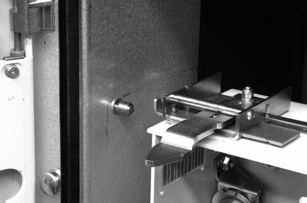
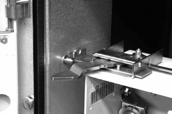
22 Circuit-breakers for ZS8.4 switchgear (fig. 5b) The socket (13) takes the connector (plug) placed in the switchgear. The slides (9) for operating the segregation shutters of the medium voltage contacts of the switchgear are fixed on the sides of the circuit-breaker. The crosspiece with the handles (17) for hooking up the circuit-breaker for the racking-in/out operations by means of the special operating lever (16) is mounted on the front part of the circuit-breaker truck. The circuit-breaker is completed with the isolating contacts (8). The withdrawable circuit-breaker is fitted with special locks, described below (see fig.5c - 5d). 1) Prevention of traverse with circuit-breaker closed With the circuit-breaker closed, the feeler pin (16 - fig. 5c) prevents the shutter sliding (19- fig. 5c) and therefore insertion of the lever (20- fig. 5c) for traverse of the apparatus. 2) Prevention of traverse with socket-plug disconnected When the plug is not inserted in the socket (13), the stem (21 - fig. 5c) prevents the plate (22 - fig. 5c) lifting and traverse of the apparatus. 3) Prevention of switchgear door closing with socketplug disconnected (*) When the plug is not inserted in the socket (13), the feeler pin (23 - fig. 5d) prevents door closing. 4) Prevention of circuit-breaker racking-out with the socket-plug connected (*) When the plug is inserted in the socket (13), the lock bolt (29 - fig. 5d) hits the pin (30 - fig. 5d) preventing the apparatus from being racked out of the switchgear Caption 1 Coupling for the manual closing spring charging lever 2 Signalling device for circuit-breaker open/closed 3 Rating plate 4 Opening pushbutton 5 Closing pushbutton 6 Signalling device for closing spring charged/discharged 7 Operation counter 8 Isolating contacts 9 Slide for operating the switchgear shutters 10 Truck 11 Locks for hooking into the fixed part 13 Connector (plug) 16 Operating lever for circuit-breaker racking-in/out (a special version is provided for VD4/ZS8 Preussen Elektra EON circuit-breakers) 17 Handles for activating the locks (11) (*) Only VD4/ZS8 Preussen - Elektra EON version. Fig. 5b 20


23 Fig. 5c Fig. 5d 21
24 General characteristics of withdrawable circuit-breakers for UniGear ZS1 switchgear General characteristics of withdrawable circuit-breakers for UniGear ZS1 switchgear (12 kv) Circuit-breaker VD4/P 12 Standards IEC VDE 0671; CEI 17-1 (File 1375) Rated voltage Ur [kv] 12 Rated insulation voltage Us [kv] 12 Withstand voltage at 50 Hz Ud (1 min) [kv] 28 Impulse withstand voltage Up [kv] 75 Rated frequency fr [Hz] Rated normal current (40 C) (1) Ir [A] Rated breaking capacity Isc [ka] (rated short-circuit breaking current symmetrical) Rated short-time withstand current (3s) Ik [ka] Making capacity Ip [ka] Operation sequence [ O s - CO - 15 s - CO ] Opening time [ms] Arcing time [ms] Total breaking time [ms] Closing time [ms] P P H [mm] Maximum W [mm] overall H dimensions D [mm] W D Pole distance P [mm] Weight [kg] Standardised table of dimensions TN VCD Operating temperature [ C] Tropicalization IEC: , Electromagnetic compatibility IEC: (1) Rated current guaranteed with circuit-breaker installed in UniGear ZS1 switchgear and with 40 C ambient temperature. (2) With forced ventilation. 22
25 (2) 4000 (2)
26 General characteristics of withdrawable circuit-breakers for UniGear ZS1 switchgear (17.5 kv) Circuit-breaker VD4/P 17 Standards IEC VDE 0671; CEI 17-1 (File 1375) Rated voltage Ur [kv] 17.5 Rated insulation voltage Us [kv] 17.5 Withstand voltage at 50 Hz Ud (1 min) [kv] 38 Impulse withstand voltage Up [kv] 95 Rated frequency fr [Hz] Rated normal current (40 C) (1) Ir [A] Rated breaking capacity Isc [ka] (rated short-circuit breaking current symmetrical) Rated short-time withstand current (3s) Ik [ka] Making capacity Ip [ka] Operation sequence [O s - CO - 15 s - CO] Opening time [ms] Arcing time [ms] Total breaking time [ms] Closing time [ms] P P H [mm] Maximum W [mm] overall H dimensions D [mm] W D Pole distance P [mm] Weight [kg] Standardised table of dimensions TN VCD Operating temperature [ C] Tropicalization IEC: , Electromagnetic compatibility IEC: (1) Rated current guaranteed with circuit-breaker installed in UniGear ZS1 switchgear and with 40 C ambient temperature. (2) With forced ventilation. 24
27 17,5 17, (2) 4000 (2) ,5 31,5 31,5 31,5 31, ,5 31,5 31,5 31,5 31,
![General characteristics of withdrawable circuit-breakers for UniGear ZS1 switchgear (24 kv) Circuit-breaker VD4/P 24 Standards IEC 62271-100 VDE 0671; CEI 17-1 (File 1375) Rated voltage Ur [kv] 24](/docs-images/92/109156106/images/28-0.jpg "Rated insulation voltage Us [kv] 24 Withstand voltage at 50 Hz Ud (1 min) [kv] 50 Impulse withstand voltage Up [kv] 125 Rated frequency fr [Hz] 50-60 Rated normal current (40 C) (1) Ir [A] 630 630")
28 General characteristics of withdrawable circuit-breakers for UniGear ZS1 switchgear (24 kv) Circuit-breaker VD4/P 24 Standards IEC VDE 0671; CEI 17-1 (File 1375) Rated voltage Ur [kv] 24 Rated insulation voltage Us [kv] 24 Withstand voltage at 50 Hz Ud (1 min) [kv] 50 Impulse withstand voltage Up [kv] 125 Rated frequency fr [Hz] Rated normal current (40 C) (1) Ir [A] (2) Rated breaking capacity (rated short-circuit breaking current symmetrical) Isc [ka] Rated short-time withstand current (3s) Ik [ka] Making capacity Ip [ka] Operation sequence [O s - CO - 15 s - CO] Opening time [ms] Arcing time [ms] Total breaking time [ms] Closing time [ms] P P H [mm] Maximum W [mm] overall H dimensions D [mm] W D Pole distance P [mm] Weight [kg] Standardised table of dimensions TN Operating temperature [ C] Tropicalization IEC: , Electromagnetic compatibility IEC: (1) Rated current guaranteed with circuit-breaker installed in UniGear ZS1 switchgear and with 40 C ambient temperature. (2) 2300 A rated current guaranteed with natural ventilation; 2500 A rated current guaranteed with forced ventilation. 26
 [kv] 70 Impulse withstand voltage Up [kv] 170 Rated frequency fr [Hz] 50-60 Rated normal current (40 C)")
29 General characteristics of withdrawable circuit-breakers for UniGear ZS2 switchgear and PowerCube modules (36 kv) Circuit-breaker VD4/W 36 Standards IEC VDE 0671; CEI 17-1 (File 1375) Rated voltage Ur [kv] 36 Rated insulation voltage Us [kv] 36 Withstand voltage at 50 Hz Ud (1 min) [kv] 70 Impulse withstand voltage Up [kv] 170 Rated frequency fr [Hz] Rated normal current (40 C) (1) Ir [A] ( * ) Rated breaking capacity (rated short-circuit breaking current symmetrical) Isc [ka] 31,5 31,5 31,5 31,5 Rated short-time withstand current (3s) Ik [ka] 31,5 31,5 31,5 31,5 Making capacity Ip [ka] Operation sequence [O s - CO - 15 s - CO] Opening time [ms] Arcing time [ms] Total breaking time [ms] Closing time [ms] P P H [mm] Maximum W [mm] overall H dimensions D [mm] W D Pole distance P [mm] Weight [kg] Standardised table of dimensions TN 1VYN KG 1VYN KG 1VYN KG Operating temperature [ C] Tropicalization IEC: , Electromagnetic compatibility IEC: (*) Ask ABB 27
30 Types of withdrawable circuit-breakers available for UniGear ZS1 switchgear VD4 withdrawable circuit-breaker (12 kv) Ur Isc Rated uninterrupted current (40 C) [A] kv 12 ka W=650 W=800 W=1000 W=1000 W=1000 P=150 P=210 P=275 P=275 P=275 u/l=205 u/l=310 u/l=310 u/l=310 u/l=310 ø=35 ø=79 ø=79 ø=109 ø=109 Circuit-breaker type VD4/P p VD4/P p VD4/P p VD4/P p VD4/P p VD4/P p VD4/P p VD4/P p VD4/P p VD4/P p VD4/P p VD4/P p VD4/P p VD4/P p VD4/P p VD4/P p VD4/P p VD4/P p VD4/P p VD4/P p VD4/P p VD4/P p VD4/P p VD4/P p VD4/P p VD4/P p VD4/P p VD4/P p VD4/P p VD4/P p VD4/P p VD4/P p VD4/P p VD4/P p VD4/P p VD4/P p VD4/P p VD4/P p275 31, VD4/P p VD4/P p VD4/P p VD4/P p VD4/P p275 31, VD4/P p VD4/P p VD4/P p275 W = Width of the circuit-breaker. P = Pole horizontal centre distance. u/l = Distance between bottom and top terminal. ø = Diameter of the isolating contact. 28
31 VD4 withdrawable circuit-breaker (17.5 kv) Ur Isc Rated uninterrupted current (40 C) [A] kv 17.5 ka W=650 W=800 W=1000 W=1000 W=1000 P=150 P=210 P=275 P=275 P=275 u/l=205 u/l=310 u/l=310 u/l=310 u/l=310 ø=35 ø=79 ø=79 ø=109 ø=109 Circuit-breaker type VD4/P p VD4/P p VD4/P p VD4/P p VD4/P p VD4/P p VD4/P p VD4/P p VD4/P p VD4/P p VD4/P p VD4/P p VD4/P p VD4/P p VD4/P p VD4/P p VD4/P p VD4/P p VD4/P p VD4/P p VD4/P p VD4/P p VD4/P p VD4/P p VD4/P p VD4/P p VD4/P p VD4/P p VD4/P p VD4/P p VD4/P p VD4/P p VD4/P p VD4/P p VD4/P p VD4/P p VD4/P p VD4/P p275 31, VD4/P p VD4/P p VD4/P p VD4/P p VD4/P p275 31, VD4/P p VD4/P p VD4/P p275 W = Width of the circuit-breaker. P = Pole horizontal centre distance. u/l = Distance between bottom and top terminal. ø = Diameter of the isolating contact. 29
32 VD4 withdrawable circuit-breaker (24 kv) Ur Isc Rated uninterrupted current (40 C) [A] kv 24 ka W=800 W=1000 W=1000 P=210 P=275 P=275 u/l=310 u/l=310 u/l=310 ø=79 ø=79 ø=109 Circuit-breaker type VD4/P p VD4/P p VD4/P p VD4/P p VD4/P p VD4/P p VD4/P p VD4/P p VD4/P p VD4/P p VD4/P p VD4/P p VD4/P p VD4/P p VD4/P p VD4/P p VD4/P p VD4/P p VD4/P p VD4/P p VD4/P p275 W = Width of the switchgear. P = Pole horizontal centre distance. u/l = Distance between bottom and top terminal. ø = Diameter of the isolating contact. VD4 withdrawable circuit-breaker (36 kv) Ur Isc Rated uninterrupted current (40 C) [A] Pole type H=951 D=788 kv ka u/l=380 Circuit-breaker type ø=399 ø=399 ø=399 ø=399 P=275 P=275 P=275 P=275 W=778 W=778 W=778 W= A VD4/W p A VD4/W p A VD4/W p A ( * ) VD4/W p275 H = Height of the circuit-breaker. D = Depth of the circuit-breaker. u/l = Distance between bottom and top terminal. ø = Diameter of the isolating contact. P = Pole horizontal centre distance. W = Width of the circuit-breaker. (*) = To be released. Contact ABB 30

 and four break contacts (signalling")
33 VD4 up to 24 kv VD4 up to 24 kv VD4-36 kv Standard fittings of withdrawable circuit-breakers for UniGear ZS1 switchgear (up to 24 kv) - UniGear ZS2 and PowerCube modules (VD4 36 kv). The basic versions of the withdrawable circuit-breakers are three-pole and fitted with: EL type manual operating mechanism mechanical signalling device for closing spring charged/ discharged mechanical signalling device for circuit-breaker open/closed closing pushbutton opening pushbutton operation counter set of ten auxiliary circuit-breaker open/closed contacts Note: with the set of ten auxiliary contacts supplied as standard and the maximum number of electrical applications possible, three make contacts (signalling circuit-breaker open) and four break contacts (signalling circuitbreaker closed) are available. lever for manually charging the closing spring isolating contacts cord with connector (plug only) for auxiliary circuits, with striker pin which does not allow connection of the plug in the socket if the rated current of the circuit-breaker is different from the rated current of the panel racking-in/out lever (the quantity must be defined according to the number of pieces of apparatus ordered) locking electromagnet in the truck. This prevents the circuitbreaker from being racked into the panel with auxiliary circuits not connected (plug not inserted in the socket). 31
34 General characteristics of withdrawable circuit-breakers for PowerCube modules General characteristics of withdrawable circuit-breakers for PowerCube modules (12 kv) Circuit-breaker VD4/P 12 VD4/W 12 Standards PowerCube module PB1 IEC VDE 0671; CEI 17-1 (File 1375) Rated voltage Ur [kv] Rated insulation voltage Us [kv] Withstand voltage at 50 Hz Ud (1 min) [kv] Impulse withstand voltage Up [kv] Rated frequency fr [Hz] Rated normal current (40 C) (1) Ir [A] Rated breaking capacity (rated short-circuit breaking Isc [ka] current symmetrical) Rated short-time Ik [ka] withstand current (3s) Making capacity Ip [ka] Operation sequence [O s - CO - 15 s - CO] Opening time [ms] Arcing time [ms] Total breaking time [ms] Closing time [ms] P P H [mm] Maximum W [mm] overall H dimensions D [mm] W D Pole distance P [mm] Weight [kg] Standardised table of dimensions TN VCD Operating temperature [ C] Tropicalization IEC: , Electromagnetic compatibility IEC: (1) Rated current guaranteed with circuit-breaker installed in PowerCube enclosure and with 40 C ambient temperature (2) With forced ventilation PB2 32
35 VD4/P 12 VD4/W 12 PB2 PB3 PB (2) (2) ,5 31,5 31,5 31,5 31, ,5 31,5 31,5 31,5 31,
36 General characteristics of withdrawable circuit-breakers for PowerCube modules (17.5 kv) Circuit-breaker VD4/P 17 VD4/W 17 Standards PowerCube module PB1 IEC VDE 0671; CEI 17-1 (File 1375) Rated voltage Ur [kv] Rated insulation voltage Us [kv] Withstand voltage at 50 Hz Ud (1 min) [kv] Impulse withstand voltage Up [kv] Rated frequency fr [Hz] Rated normal current (40 C) (1) Ir [A] Rated breaking capacity (rated short-circuit breaking Isc [ka] current symmetrical) Rated short-time Ik [ka] withstand current (3s) Making capacity Ip [ka] Operation sequence [O s - CO - 15 s - CO] Opening time [ms] Arcing time [ms] Total breaking time [ms] Closing time [ms] P P H [mm] Maximum W [mm] overall H dimensions D [mm] W D Pole distance P [mm] Weight [kg] Standardised table of dimensions TN VCD Operating temperature [ C] Tropicalization IEC: , Electromagnetic compatibility IEC: (1) Rated current guaranteed with circuit-breaker installed in PowerCube enclosure and with 40 C ambient temperature. (2) With forced ventilation PB2 34
37 VD4/P 17 VD4/W 17 PB2 PB3 PB3 17,5 17,5 17,5 17,5 17,5 17, (2) (2)
38 General characteristics of withdrawable circuit-breakers for PowerCube modules (24 kv) Circuit-breaker VD4/P 24 PowerCube module PB4 PB5 Standards IEC VDE 0671; CEI 17-1 (File 1375) Rated voltage Ur [kv] Rated insulation voltage Us [kv] Withstand voltage at 50 Hz Ud (1 min) [kv] Impulse withstand voltage Up [kv] Rated frequency fr [Hz] Rated normal current (40 C) (1) Ir [A] (2) Rated breaking capacity (rated short-circuit breaking Isc [ka] current symmetrical) Rated short-time withstand current (3s) Ik [ka] Making capacity Ip [ka] Operation sequence [O s - CO - 15 s - CO] Opening time [ms] Arcing time [ms] Total breaking time [ms] Closing time [ms] P P H [mm] Maximum W [mm] overall H dimensions D [mm] W D Pole distance P [mm] Weight [kg] Standardised table of dimensions TN Operating temperature [ C] Tropicalization IEC: , Electromagnetic compatibility IEC: (1) Rated current guaranteed with circuit-breaker installed in PowerCube enclosure and with 40 C ambient temperature. (2) 2300 A rated uninterrupted current guaranteed with natural ventilation; 2500 A rated current guaranteed with forced ventilation. 36
39 Types of withdrawable circuit-breakers available for PowerCube modules VD4 withdrawable circuit-breaker (12 kv) Ur Isc Rated uninterrupted current (40 C) [A] kv 12 ka W=650 W=800 W=1000 W=1000 W=1000 P=150 P=210 P=275 P=275 P=275 u/l=205 u/l=310 u/l=310 u/l=310 u/l=310 ø=35 ø=79 ø=79 ø=109 ø=109 Circuit-breaker type VD4/P p VD4/P p VD4/P p VD4/P p VD4/P p VD4/P p VD4/P p VD4/P p VD4/W p VD4/W p VD4/W p VD4/W p VD4/W p VD4/W p VD4/W p VD4/W p VD4/P p VD4/P p VD4/P p VD4/P p VD4/P p VD4/P p VD4/P p VD4/P p VD4/P p VD4/P p VD4/P p VD4/P p VD4/P p VD4/P p VD4/P p VD4/P p VD4/P p VD4/W p VD4/W p VD4/W p VD4/W p VD4/W p VD4/W p VD4/W p VD4/W p VD4/W p VD4/W p275 W = Width of the switchgear. P = Pole horizontal centre distance. u/l = Distance between bottom and top terminal. ø = Diameter of the isolating contact. 37
40 VD4 withdrawable circuit-breaker (17.5 kv) Ur Isc Rated uninterrupted current (40 C) [A] kv 17,5 ka W=650 W=800 W=1000 W=1000 W=1000 P=150 P=210 P=275 P=275 P=275 u/l=205 u/l=310 u/l=310 u/l=310 u/l=310 ø=35 ø=79 ø=79 ø=109 ø=109 Circuit-breaker type VD4/P p VD4/P p VD4/P p VD4/P p VD4/P p VD4/P p VD4/P p VD4/P p VD4/W p VD4/W p VD4/W p VD4/W p VD4/W p VD4/W p VD4/W p VD4/W p VD4/P p VD4/P p VD4/P p VD4/P p VD4/P p VD4/P p VD4/P p VD4/P p VD4/P p VD4/P p VD4/P p VD4/P p VD4/P p VD4/P p VD4/P p VD4/P p VD4/P p VD4/W p VD4/W p VD4/W p VD4/W p VD4/W p VD4/W p VD4/W p VD4/W p VD4/W p VD4/W p275 W = Width of the switchgear. P = Pole horizontal centre distance. u/l = Distance between bottom and top terminal. ø = Diameter of the isolating contact. 38
![VD4 withdrawable circuit-breaker (24 kv) Ur Isc Rated uninterrupted current (40 C) [A] W=800 W=1000 kv ka P=210 P=275 Circuit-breaker type u/l=310 u/l=310 ø=35 ø=79 16 630 VD4/P 24.06.](/docs-images/92/109156106/images/41-0.jpg "16 p210 20 630 VD4/P 24.06.20 p210 25 630 VD4/P 24.06.25 p210 16 1250 VD4/P 24.12.16 p210 20 1250 VD4/P 24.12.20 p210 25 1250 VD4/P 24.12.25 p210 16 1600 VD4/P 24.16.16 p275 24 20 1600 VD4/P 24.16.20 p275 25 1600 VD4/P 24.")

41 VD4 withdrawable circuit-breaker (24 kv) Ur Isc Rated uninterrupted current (40 C) [A] W=800 W=1000 kv ka P=210 P=275 Circuit-breaker type u/l=310 u/l=310 ø=35 ø= VD4/P p VD4/P p VD4/P p VD4/P p VD4/P p VD4/P p VD4/P p VD4/P p VD4/P p VD4/P p VD4/P p VD4/P p VD4/P p VD4/P p VD4/P p275 W = Width of the switchgear. P = Pole horizontal centre distance. u/l = Distance between bottom and top terminal. ø = Diameter of the isolating contact Standard fittings for withdrawable circuit-breakers for PowerCube modules The basic versions of the withdrawable circuit-breakers are always three-pole and fitted with: EL type manual operating mechanism mechanical signalling device for closing spring charged/ discharged mechanical signalling device for circuit-breaker open/closed closing pushbutton opening pushbutton operation counter set of ten auxiliary circuit-breaker open/closed contacts Note: with the group of ten auxiliary contacts supplied as standard and the maximum number of electrical applications, three make contacts (signalling circuit-breaker open) and four break contacts (signalling circuit-breaker closed) are available. lever for manually charging the closing spring isolating contacts cord with connector (only plug) for auxiliary circuits, with striker pin which does not allow connection of the plug in the socket if the rated current of the circuit-breaker is different from the rated current of the panel racking-in/out lever (the quantity must be defined according to the number of pieces of apparatus ordered) locking electromagnet in the truck. This prevents racking-in of the circuit-breaker in the panel with auxiliary circuits not connected (plug not inserted in the socket). 39
 VD4/Z8 Width [kv] 650 650 650 650 800 800 Depth [kv] 1000 1000 1000 1000 1200 1200 IEC")
42 General characteristics of withdrawable circuit-breakers for ZS8.4 switchgear Circuit-breaker Standards Panel without partitions Panel with partitions Preussen Elektra - EON (2) VD4/Z8 Width [kv] Depth [kv] IEC VDE 0671 Rated voltage Ur [kv] Rated insulation voltage Us [kv] Withstand voltage at 50 Hz Ud (1 min) [kv] Impulse withstand voltage Up [kv] Rated frequency fr [Hz] Rated normal current (40 C) (1) Ir [A] Rated breaking capacity (rated symmetrical Isc [ka] short-circuit current) Rated short-time withstand current(3 s) Ik [ka] Making capacity Ip [ka] 18,5 mm Operation sequence [O-0.3s-CO-15s-CO] Opening time [ms] Arcing time [ms] Total breaking time [ms] Closing time [ms] P P H [mm] Maximum W [mm] overall H dimensions D [mm] W D Pole distance P [mm] Weight [kg] Standardised table of dimensions 1VCD Operating temperature [ C] Tropicalisation IEC IEC Electromagnetic compatibility IEC (1) Rated current guaranteed with circuit-breaker installed in switchgear with 40 C ambient temperature. (2) Special type with device for charging the closing spring by means of a rotary handle outside the operating mechanism. 40
43 VD4/ZT8 VD4/ZS
44 General characteristics of withdrawable circuit-breakers for ZS8.4 switchgear VD4/ZS8 - VD4/ZT8 - VD4/Z8 withdrawable circuit-breaker for ZS8.4 switchgear Ur Isc Rated uninterrupted current (40 C) [A] kv ka Panel with partition Panel without partition Special panel EON W = 650 W = 800 W = 650 W = 800 W = 650 W = 800 P = 150 P = 210 P = 150 P = 210 P = 150 P = 210 u/l = 205 u/l = 310 u/l = 205 u/l = 310 u/l = 205 u/l = 310 ø = 35 ø = 35 ø = 35 ø = 35 ø = 35 ø = 35 Circuit-breaker type VD4/ZS p VD4/ZS p VD4/ZS p VD4/ZS p VD4/ZT p VD4/ZT p VD4/ZT p VD4/ZT p VD4/ZS p VD4/ZS p VD4/ZS p VD4/ZS p VD4/Z p VD4/Z p VD4/Z p VD4/Z p VD4/ZT p VD4/ZT p VD4/ZT p VD4/ZT p VD4/ZS p VD4/ZS p VD4/ZS p VD4/ZS p VD4/ZS p VD4/ZS p VD4/ZT p VD4/ZT p VD4/ZT p VD4/ZT p VD4/ZT p VD4/ZT p VD4/ZS p VD4/ZS p VD4/ZS p VD4/ZS p VD4/ZS p VD4/ZS p210 W = Width of the switchgear. P = Pole horizontal centre distance. u/l = Distance between bottom and top terminal. ø =Diameter of the isolating contact. 42

45 Standard fittings for withdrawable circuit-breakers for ZS8.4 switchgear The basic versions of the withdrawable circuit-breakers are always three-pole and fitted with: EL type manual operating mechanism mechanical signalling device for closing spring charged/ discharged mechanical signalling device for circuit-breaker open/closed closing pushbutton opening pushbutton operation counter set of ten auxiliary circuit-breaker open/closed contacts Note: with the set of ten auxiliary contacts supplied as standard and the maximum number of electrical applications possible, three make contacts (signalling circuit-breaker open) and four break contacts (signalling circuitbreaker closed) are available. lever for manually charging the closing springs incorporated in the operating mechanism for VD4/Z8 and VD4/ZT8, external with rotary movement for VD4/ZS8 isolating contacts cord with connector (only plug) for auxiliary circuits, with striker pin which does not allow connection of the plug in the socket if the rated current of the circuit-breaker is different from the rated current of the panel racking-in/out lever (the quantity must be defined according to the number of pieces of apparatus ordered) VD4/ZS8 (Preussen Elektra-EON version) Device for recharging the closing spring, with door closed, by means of removable rotary handle and outside the operating mechanism and the switchgear 64-pin Harting socket with mechanical interlock which prevents traverse of the circuit-breaker when the plug is not inserted in the socket Interlock with the door which prevents insertion of the spring charging lever when the circuit-breaker is closed Interlock with the door and the 64-pin Harting socket which prevents door closure when the plug is not inserted in the socket VD4/Z8 - VD4/ZT8 Harting 64-pin socket with mechanical interlock which prevents traverse of the circuit-breaker when the plug is not inserted in the socket Caption 1) Device for spring charging with rotary handle 2) Harting 64-pin socket with mechanical interlock which prevents traverse when the socket is not inserted 3) Door-socket-spring charging device interlock (only VD4/ZS8 version) 43
 switchgear Circuit-breaker VD4/US 24 (3) VD4/US 24 (4) Standards UniSwitch (unit CBW type) UniMix")
46 General characteristics of withdrawable circuit-breakers for UniSwitch switchgear and UniMix (24 kv) switchgear Circuit-breaker VD4/US 24 (3) VD4/US 24 (4) Standards UniSwitch (unit CBW type) UniMix (unit P1/E type) IEC VDE 0671; CEI 17-1 (File 1375) Rated voltage Ur [kv] Rated insulation voltage Us [kv] Withstand voltage at 50 Hz Ud (1 min) [kv] Impulse withstand voltage Up [kv] Rated frequency fr [Hz] Rated normal current (40 C) (1) Ir [A] Rated breaking capacity 16 (20) (5) 16 (25) (5) Isc [ka] (rated symmetrical short-circuit current) 20 (25) (5) 20 (25) (5) Rated short-time 16 (20) (5) 16 (25) (5) Ik [ka] withstand current (3 s) (2) 20 (25) (5) 20 (25) (5) Making capacity Ip [ka] 40 (50) (5) 40 (63) (5) (63) (5) 40 (63) (5) Operation sequence [O s - CO - 15 s - CO] Opening time [ms] Arcing time [ms] Total breaking time [ms] Closing time [ms] P P H [mm] Maximum W [mm] overall H dimensions D [mm] W D Pole distance P [mm] Weight [kg] Standardised table of dimensions 1VCD Operating temperature [ C] Tropicalization IEC: , Electromagnetic compatibility IEC (1) Rated current guaranteed with withdrawable circuit-breaker installed in switchgear with 40 C ambient temperature (2) The value and duration of the rated short-time withstand current depends on the switchgear. See the specific catalogues of the UniSwitch and UniMix switchgear (3) The top shutter activation wheels of the UniSwitch switchgear (CBW unit) are mounted and adjusted by the manufacturer of the UniSwitch switchgear (4) The top shutter activation wheels of the UniMix switchgear (P1/E unit) are available on request (5) The values in brackets refer to the 12 kv rated voltage. 44
47 Standard fittings for withdrawable circuit-breakers for UniSwitch and UniMix switchgear The basic versions of the withdrawable circuit-breakers are three-pole and provided with: EL type manual operating mechanism Mechanical signalling device for closing spring charged/ discharged Mechanical signalling device for circuit-breaker open/closed Closing pushbutton Opening pushbutton Operation counter Set of ten circuit-breaker open/closed auxiliary contacts Note: with the set of ten auxiliary contacts supplied as standard and the maximum electrical accessories, three break contacts are available (signalling circuit-breaker open) and four make contacts (signalling circuitbreaker closed). Lever for manual charging of the closing spring incorporated in the operating mechanism Isolating contacts Racking-out/racking-in lever (the quantity must be established according to the number of pieces of apparatus ordered). VD4 withdrawable circuit-breaker for switchgear UniSwitch (type unit CBW) and UniMix (type unit P1/E) Ur Isc Rated uninterrupted current (40 C) [A] UniSwitch CBW UniMix P1/E kv ka P=210 P=210 u/l=310 u/l=310 Circuit-breaker type ø=35 ø= (1) 630 VD4/US p (1) 630 VD4/US p VD4/US p (1) 1250 VD4/US p (1) 1250 VD4/US p VD4/US p210 (1) 25 ka Isc at the 12 kv rated voltage P = Pole horizontal centre distance. u/l = Distance between bottom and top terminal. ø = Diameter of the isolating contact Characteristics of the electrical accessories Shunt opening release (-MO1) Additional shunt opening release (-MO2) Shunt closing release (-MC) Locking magnet on the actuator (-RL1) Un V Un V~ 50 Hz Un V~ 60 Hz Operating limits % Un Inrush power (Ps) DC 200 W; AC = 200 VA Inrush time approx. 100 ms Continuous power (Pc) DC = 5 W; AC = 5 VA Opening time ms Closing time ms Insulation voltage 2000 V 50 Hz (for 1 min) Undervoltage release (-MU) Un V Un V~ 50 Hz Un V~ 60 Hz Operating limits circuit-breaker opening 35-70% Un circuit-breaker closing % Un Inrush power (Ps) DC 200 W; AC = 200 VA Inrush time approx. 100 ms Continuous power DC = 5 W; AC = 5 VA Opening time 30 ms Insulation voltage 2000 V 50 Hz (for 1 min) Electronic time delay device for undervoltage release (mounted outside the circuit-breaker) Un V Un V~ 50/60 Hz Adjustable opening time (release + time delay s device) 45
48 Motor for motorised truck (-MT) (only for withdrawable circuit-breakers for UniGear ZS1 and ZS8.4 switchgear) Un Operating limits Rated power (Pn) Motor operator (-MS) V DC % Un 40 W Characteristics Un V Un V ~ 50/60 Hz Operating limits % Un 40 ka 50 ka Inrush power (Ps) DC=600 W; AC=600 VA DC=900 W; AC=900 VA Rated power (Pn) DC=200 W; AC=200 VA DC=350 W; AC=350 VA Inrush time 0.2 s 0.2 s Charging time 6-7 s 6-7 s Insulation voltage 2000 V 50 Hz (for 1 min) 2000 V 50 Hz (for 1 min) Auxiliary contacts of the circuit-breaker Rated insulation voltage according to VDE 0110, Group C 660 V AC 800 V DC Rated voltage 24 V V Insulation-test test voltage 2.5 kv Maximum rated current 10 A Number of contacts 5 Stroke 6 mm... 7 mm Contact force 26 N On resistance 3 mω Storing temperature range - 20 C C Operating temperature range - 20 C C Contact over temperature 20 K Operating cycles 30,000 Unlimited short circuit stability by using fuses of max. 10 A time-lag Cosϕ Rated current Breaking capacity 220 V AC A 25 A 380 V AC A 15 A 500 V AC A 15 A 660 V AC A 12 A Time constant 1 ms 10 A 12 A 24 V DC 15 ms 10 A 12 A 50 ms 8 A 10 A 200 ms 4 A 7.7 A 1 ms 8 A 10 A 60 V DC 15 ms 6 A 8 A 50 ms 5 A 6 A 200 ms 4 A 5.4 A 1 ms 6 A 8 A 110 V DC 15 ms 4 A 5 A 50 ms 2 A 4.6 A 200 ms 1 A 2.2 A 1 ms 1.5 A 2 A 220 V DC 15 ms 1 A 1.4 A 50 ms 0.75 A 1.2 A 200 ms 0.5 A 1 A Note With the set of 10 auxiliary contacts supplied as standard, the following are available: 3 NO contacts + 5 NC contacts for fixed circuit-breakers 3 NO contacts + 4 NC contacts for withdrawable circuit-breakers With the set of 15 auxiliary contacts (+5 contacts on request compared to the 10 supplied as standard), the following are available: for fixed circuit-breaker, as desired, 6 NO contacts + 7 NC contacts or 5 NO contacts + 8 NC contacts or 3 NO contacts + 10 NC contacts for withdrawable circuit-breakers, depending on the applications required, a maximum of 6 NO contacts + 6 NC contacts and a minimum of 5 NO contacts + 5 NC contacts are available. Locking magnet on the truck (-RL2) (*) Un Un Operating limits Inrush power (Ps) Continuous power (Pc) Inrush time V V~ 50/60 Hz % Un DC = 250 W; AC = 250 VA DC = 5 W; AC = 5 VA 150 ms (*) Not available for versions with motorized truck. 46

49 6. Instructions for operating the circuit-breaker 6.1. Safety indications The VD4 circuit-breakers guarantee a minimum IP2X degree of protection when installed in the following conditions: fixed circuit-breaker, installed behind a protective metal net withdrawable circuit-breaker, installed in switchgear. Under these conditions the operator is totally guaranteed against accidental contact with moving parts. Should mechanical operations be carried out on the circuit-breaker outside of the switchgear, take great care of the moving parts. If the operations are prevented, do not force the mechanical interlocks and check that the operating sequence is correct. Racking the circuit-breaker in and out of the switchgear must be done gradually to avoid shocks which may deform the mechanical interlocks Switching and signalling parts VD4 circuit-breakers for UniGear switchgear and PowerCube modules (fig. 6a) Mechanical override of the undervoltage release (on request) Undervoltage release enabled. The circuit-breaker can only be closed if the undervoltage release is supplied with power. Undervoltage release disabled. The circuit-breaker can also be closed if the undervoltage release is not supplied with power Caption 1 Key lock (if provided) (*) 2 Lever for manually charging the closing spring 3 Coupling lever for racking-out operation (only VD4/ZS8 version) 4 Opening pushbutton 5 Closing pushbutton 6 Signalling device for circuit-breaker open/closed 7 Signalling device for closing springs charged/discharged 8 Operation counter. 9 Handles for operating the truck locks (only for withdrawable circuit-breakers) 10 Operating lever for circuit-breaker racking-in/out (there is a special version for VD4/ZS8) 11 Mechanical undervoltage release override (on request). (*) Warning! To activate the key lock: open the circuit-breaker, keep the opening pushbutton depressed, then turn the key and remove it from the housing. Fig. 6a 47
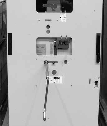
50 6.3. Circuit-breaker closing and opening operations Circuit-breaker operation can be either manual or electrical (fig. 6 - fig. 7). a1) Manual closing spring charging for VD4 circuitbreakers for UniGear switchgear and PowerCube modules (fig. 7a) Repeatedly activate the charging lever (2) (maximum rotation angle of the lever: about 90 ) until the yellow indicator (7) appears. The maximum forces which can normally be applied to the lever are <150 N for the EL1operating mechanism, <200 N for the EL2 operating mechanism and <250 N for EL3 operating mechanism. EL1 Twin and EL2 Twin type operating mechanisms are provided for circuit-breakers with 50 ka breaking capacity. For manual charging, the additional lever (1) should be inserted fully, as indicated in fig. 7c. In this way, the maximum force to be applied is < 200 N. For the type of operating mechanism, please refer to the rating plate in fig. 1. VD4 circuit-breakers for ZS8.4 switchgear (fig. 6b) a2) Manual closing spring charging for VD4/ZS8 circuitbreakers (fig. 7b) Rotate the charging lever (2) (rotate about 12 times) until the yellow indicator (7) appears. The maximum force which can normally be applied to the lever is <150 N for the EL1 operating mechanism. The operation can be carried out with the door open, with the door closed, with the circuit-breaker racked-out and with the circuit-breaker racked-in. b) Electrical spring charging operation On request, the circuit-breaker can be fitted with the following accessories for electrical operation: geared motor for automatic closing spring charging shunt closing release shunt opening release. The geared motor automatically recharges the spring after each closing operation until the yellow indicator (7) appears. If the power is cut off during charging, the geared motor stops and automatically starts recharging the springs again when the power returns. In any case, it is always possible to complete the charging operation manually. c) Circuit-breaker closing The operation can only be carried out with the closing spring completely charged. For manual closing, press the pushbutton (5 - fig. 6b). When there is a shunt closing release, the operation can also be carried out remotely by means of a special control circuit. Closing having taken place is indicated by the signalling device (6 - fig. 6b). d) Circuit-breaker opening For manual opening, press the pushbutton (4 - fig. 6b). When there is a shunt opening release, the operation can also be carried out remotely by means of a special control circuit. Opening having taken place is indicated by the signalling device (6 - fig. 6b). 48
 4 Opening pushbutton 5 Closing pushbutton 6 Signalling")
51 b 2a Caption 1 Key lock (if provided) 2 Lever for manually charging the closing spring 2a Coupling for manual closing spring charging (when lever 2 is not provided) 2b Lever for manual closing spring charging for rotary charging device 3 Coupling for racking-out operation lever (only for withdrawable circuitbreakers) 4 Opening pushbutton 5 Closing pushbutton 6 Signalling device for circuit-breaker open/closed 7 Signalling device for closing spring charged/discharged 8 Operation counter. 9 Handles for operating the truck locks (only for withdrawable circuit-breakers) 10 Operating lever for circuit-breaker racking-in/out. Fig. 6b 49


52 Fig. 7a Fig. 7b 1 1 Fig. 7c 50
53 7. Installation 7.1. General Correct installation is of primary importance. The manufacturer s instructions must be carefully studied and followed. It is good practice to use gloves for handling the pieces during installation Installation and operating conditions The following Standards must be taken into particular consideration during installation and service: IEC /DIN VDE 0101 VDE 0105: Electrical installation service DIN VDE 0141: Earthing systems for installations with rated voltage above 1 kv All the accident prevention regulations in force in the relative countries Normal conditions Follow the recommendations in the IEC and Standards. In more detail: Ambient temperature Maximum + 40 C Average maximum over 24 hours + 35 C Minimum (according to class 5), apparatus for indoor installation 5 Humidity The average value of the relative humidity, measured for a period longer than 24 hours, must not exceed the 95%. The average value of the pressure of the water vapour, measured for a period longer than 24 hours, must not exceed 2.2 kpa. The average value of the relative humidity, measured for a period longer than 1 month, must not exceed the 90%. The average value of the pressure of the water vapour, measured for a period longer than 1 month, must not exceed 1.8 kpa Special conditions Installations over 1000 m a.s.l. Possible within the limits permitted by reduction of the dielectric resistance of the air. Increase in the ambient temperature Reduction in the rated current. Encourage heat dissipation with appropriate additional ventilation. Climate To avoid the risk of corrosion or other damage in areas: with a high level of humidity, and/or with rapid and big temperature variations, take appropriate steps (for example, by using suitable electric heaters) to prevent condensation phenomena. For special installation requirements or other operating conditions, please contact ABB. The areas involved by the passage of power conductors or auxiliary circuit conductors must be protected against access of any animals which might cause damage or disservices Trip curves The following graphs show the number of closing-opening cycles (No.) allowed, of the vacuum interrupters, according to the breaking capacity (Ia). Caption (Figs. 8...) No. Number of closing-opening cycles allowed for the vacuum interrupters. Ia: Breaking capacity of the vacuum interrupters. Altitude < 1000 m above sea level. 51
54 N. N. Fig. 8a Fig. 8c N. N. Fig. 8b Fig. 8d 52
55 N. N. Fig. 8e Fig. 8g N. N. Fig. 8f Fig. 8h 53
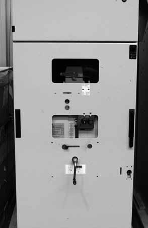
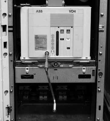
56 In = 1250 A In = 1600 A In = 1250 A N. N. In = 2000 A - 36 kv, 1250 A, 31.5 ka - 36 kv, >1600 A, 31.5 ka Fig. 8i Fig. 8l 7.3. Preliminary operations Clean the insulating parts with clean dry cloths. Check that the top and bottom terminals are clean and free of any deformation caused by shocks received during transport or storage Installation of fixed circuit-breakers The circuit-breaker can be mounted directly on supporting frames to be provided by the customer, or on a special supporting truck (available on request). The circuit-breaker, with supporting truck, must be suitably fixed to the floor of its own compartment by the customer. The floor surface in correspondence with the truck wheels must be carefully levelled. A minimum degree of protection (IP2X) must be guaranteed from the front towards live parts Mounting the circuit-breaker on a truck made by other manufacturers The VD4 circuit-breakers which are not installed on ABB trucks, but on trucks made by the customer, must be fitted with one or two additional auxiliary contacts (activated by the mechanical lock and by the circuit-breaker release device) to carry out the function of interrupting the shunt closing release circuit (-MC) during traverse from isolated and vice versa. In ABB trucks, this function is carried out by the -BT1 and -BT2 auxiliary contacts which cut of the release power supply during and before activation of the mechanical lock of the screw truck racking-in device. This means that the shunt closing release power supply can only by applied at the end of activation of the mechanical lock. In this way it is certain that no electrical impulse can activate the shunt closing release with the circuit-breaker in an intermediate position Installation of withdrawable circuitbreaker The withdrawable circuit-breakers are preset for use in UniGear ZS1, UniGear ZS2 switchgear and PowerCube modules. For racking-in/racking-out of the switchgear, fully insert the lever (1) (fig. 9) in the appropriate seat (2) and work it clockwise for racking-in, and anti-clockwise for racking-out, until the limit switch positions are reached. Circuit-breaker racking-in/-out must be carried out gradually to avoid shocks which may deform the mechanical interlocks and the limit switches. 54

57 The torque normally required to carry out racking-in and racking-out is <25 Nm. This value must not be exceeded. If operations are prevented or difficult, do not force them and check that the operating sequence is correct. Note To complete the racking-in/out operation, about 20 rotations of the lever are required for circuit-breakers up to 17.5 kv, and about 30 rotations for 24 kv circuit-breakers. When the circuit-breaker has reached the isolated for test/ isolated position, it can be considered racked into the switchgear and, at the same time, earthed by means of the truck wheels. Withdrawable circuit-breakers of the same version, and therefore with the same dimensions, are interchangeable. However, when, for example, different electrical accessory fittings are provided, a different code for the plug of the auxiliary circuits does not allow incorrect combinations between panels and circuit-breakers. For the circuit-breaker installation operations, also refer to the technical documentation of the above-mentioned switchgear. The racking-in/-out operations must always be carried out with the circuit-breaker open. When putting into service for the first time, it is advisable to charge the circuit-breaker operating mechanisms manually so as not to overload the auxiliary power suply circuit Circuit-breakers with withdrawable motorized truck Carry out the racking-in/racking-out test of the motorized truck in the same way as for a manual truck, following the instructions below: Rack the circuit-breaker into the switchgear in the open and isolated position, with the power supply to the motor circuit cut off and with the enclosure door closed. Insert the manual racking-in lever (1) in the special coupling (2) Fig. 9, and take the motorized truck to about half its run between the isolated for test and the connected position. The torque needed to carry out truck handling is < 25 Nm. In the case of accidental inversion of the truck motor power supply polarity, this operation allows a possible error in direction to be dealt with without any damage. Verification checks: a) motor rotation clockwise during circuit-breaker racking-in. b) motor rotation anticlockwise during circuit-breaker racking-out. Remove the manual lever (1) from the coupling (2) Fig. 9 Supply the truck motor circuit. Activate the control for the electrical racking-in operation. When racking-in has taken place, check correct changeover of the relative auxiliary contact. On completion, activate the control for the electrical racking-out operation. When racking-out has taken place, check correct changeover of the relative auxiliary contact. In the case of a motor fault during a racking-in or rackingout operation, in an emergency the truck can be taken to the end of its run manually, after first cutting off the power supply to the motor power supply circuit and then, using the manual lever, work in the same way as with the manual truck. Note By means of the chain transmission, truck handling carried out using the manual lever makes the truck motor armature rotate which, behaving like a generator, can cause inverse voltage at the connection terminals. This may damage the permanent magnet of the motor, therefore all the truck racking-in and racking-out operations carried out using the manual lever must be done without power supply in the motor circuit. Racking-in 2 Max 25 Nm 1 Racking-out Fig. 9 55
58 7.6. Power circuit connections of fixed circuit-breakers General recommendations Select the cross-section of the conductors according to the service current and the short-circuit current of the installation. Prepare special pole insulators, near the terminals of the fixed circuit-breaker or of the enclosure, sized according to the electrodynamic forces deriving from the short-circuit current of the installation Assembly of the connections Check that the contact surfaces of the connections are flat, and are free of any burrs, traces of oxidation or deformation caused by drilling or impacts received. According to the conductor material and the surface treatment used, carry out the operations indicated in table T1 on the contact surface of the conductor. Assembly procedure Put the connections in contact with the circuit-breaker terminals, taking care to avoid mechanical stresses (traction / compression) on, for example, the conducting busbars on the terminals. Interpose a spring washer and a flat washer between the head of the bolt and the connection. It is advisable to use bolts according to DIN class 8.8 Standards, also referring to what is indicated in table T2. In the case of cable connections, strictly follow the manufacturer s instructions to make the terminals. T1 Bare copper Clean with a fine file or emery cloth. Tighten fully and cover the contact surfaces with 5RX Moly type grease. Copper or silver-plated aluminium Clean with a rough dry cloth. Only in the case of obstinate traces of oxidation, clean with a very fine grain emery cloth taking care not to remove the surface layer. If necessary, restore the surface treatment. Bare aluminium Clean with a metal brush or emery cloth. Cover the contact surfaces again immediately with neutral grease. Insert the copper-aluminium bimetal with surfaces shined (copper side in contact with the terminal; aluminium side in contact with the connection) between the aluminium connection and the copper terminal. T2 Bolt Recommended tightening torque (1) Without lubricant With lubricant (2) M6 10 Nm 4.5 Nm M8 30 Nm 10 Nm M10 40 Nm 20 Nm M12 70 Nm 40 Nm M Nm 80 Nm (1) The nominal tightening torque is based on a friction coefficient of the thread of 0.14 (distributed value the thread is subjected to which, in some cases, is not negligible). The nominal tightening torque with lubricant is according to the DIN Standards. (2) Oil or grease. The thread and surfaces in contact with the lubricated heads. Take into account the deviations from the general Standards table (for example, for systems in contact or terminals) as foreseen in the specific technical documentation. The thread and surfaces in contact with the heads of bolts must be slightly oiled or greased, so as to obtain a correct nominal tightening torque Earthing For the fixed version circuit-breaker, carry out earthing by means of the special screw marked with the relative symbol. Clean and degrease the area around the screw to a diameter of about 30 mm and, on completion of assembly, cover the joint again with Vaseline grease. Use a conductor (busbar or braid) with a cross-section conforming to the Standards in force Connection of the auxiliary circuits Note: the minimum cross-section of the wires used for the auxiliary circuits must not be less than the one used for the internal cabling. Furthermore, they must be insulated for 3 kv of test Fixed circuit-breaker Connection of the circuit-breaker auxiliary circuits must be made by means of the terminal box (1) (fig. 10) mounted inside the circuit-breaker and the cables must pass through the connector (2). Outside the connector, the cables must pass through a suitable metal protective cover (pipe, wiring duct, etc.), which must be earthed. To prevent the cabling wires outside the circuit-breaker (carried out by the customer) from accidentally coming into contact with moving parts and therefore undergoing damage to the insulation, it is recommended to fix the wires as shown in fig. 10a. Before removing the operating mechanism cover to access the terminal box, check that the circuitbreaker is open and the closing spring discharged Withdrawable circuit-breakers The auxiliary circuits of withdrawable circuit-breakers are fully cabled in the factory as far as the connector (fig. 11). For the external connections, refer to the electric wiring diagram of the switchgear. 56


59 VD4 circuit-breaker for UniGear switchgear and PowerCube module. 1 2 Fig. 10 VD4 circuit-breaker for ZS8.4 switchgear (VD4/ZS8 version with rotary charging). Fig. 10a Fig
60 8. Putting into service 8.1. General procedures All the operations regarding putting into service must be carried out by ABB personnel or by suitably qualified customer personnel with in-depth knowledge of the apparatus and of the installation. Should the operations be prevented, do not force the mechanical interlocks and check that the operating sequence is correct. The operating forces which can be applied for racking-in withdrawable circuit-breakers are indicated in paragraph 7.5. Before putting the circuit-breaker into service, carry out the following operations: check tightness of the power connections to the circuitbreaker terminals; establish the setting of the primary electronic overcurrent release (if provided); check that the value of the power supply voltage of the auxiliary circuits is between 85% and 110% of the rated voltage of the electrical accessories; check that no foreign bodies, such as bits of packing, have got into the moving parts; check that there is a sufficient exchange of air in the installation place to avoid overtemperatures; also carry out the checks indicated in table T3. 58
61 T3 ITEM INSPECTED PROCEDURE POSITIVE CHECK 1 Insulation resistance. Medium voltage circuit With a 2500 V megger, measure the insulation resistance between the phases and the exposed conductive part of the circuit. Auxiliary circuits With a 500 V megger (if the apparatus installed allows this), measure the insulation resistance between the auxiliary circuits and the exposed conductive part. 2 Auxiliary circuits. Check that the connections to the control circuit are correct: proceed at the relative power supply. 3 Manual operating mechanism. Carry out a few closing and opening operations (see cap. 6). N.B. Supply the undervoltage release and the locking magnet on the operating mechanism at the relative rated voltage (if provided). 4 Motor operator (if provided). Supply the spring charging geared motor at the relative rated voltage. 5 Undervoltage release (if provided). 6 Shunt opening release and additional shunt opening release (if provided). 7 Shunt closing release (if provided). Carry out a few closing and opening operations.n.b. Supply the undervoltage release and the locking magnet on the operating mechanism at the relative rated voltage (if provided). Supply the undervoltage release at the relative rated voltage and carry out the circuit-breaker closing operation. Cut off power to the release. Close the circuit-breaker and supply the shunt opening release at the relative rated voltage. Open the circuit-breaker and supply the shunt closing release at the relative rated voltage. 8 Key lock (if provided). Open the circuit-breaker, keep the opening pushbutton depressed, then turn the key and remove it from the housing. Attempt the circuit-breaker closing operation. Put the key back in and turn it 90. Carry out the closing operation. 9 Locking electromagnet (-RL1) (if provided). 10 Auxiliary contacts in the operating mechanism. 11 Locking electromagnet on the truck circuit-breaker (-RL2) (if provided). 12 Auxiliary transmitted contacts for signalling circuit-breaker racked-in, isolated (UniGear switchgear of PowerCube modules). With the circuit-breaker open, spring charged and locking electromagnet not supplied, attempt circuit-breaker closing both manually and electrically. Insert the auxiliary contacts in suitable signalling circuits. Carry out a few closing and opening operations. With the circuit-breaker open, in the isolated for test position and the locking electromagnet not supplied, attempt racking-in of the circuit-breaker. Supply the locking electromagnet and carry out the racking-in operation. Insert the auxiliary contacts in suitable signalling circuits. With the circuit-breaker racked into the enclosure, carry out a few traverse operations from the isolated for test position to the connected position. Take the circuit-breaker to the racked-out position. The insulation resistance should be at least 50 Mohm and in any case constant over time. The insulation resistance should be a few Mohm and in any case constant over time. Operations and signals normal. The operations and relative signals take place normally. The spring is charged normally. The signals are normal. With the spring charged, the geared motor stops. The geared motor recharges the spring after each closing operation. The circuit-breaker closes normally. The signals are normal. The circuit-breaker opens. The signalling changes over. The circuit-breaker opens normally. The signals are normal. The circuit-breaker opens normally. The signals are normal. Neither manual nor electrical closing takes place. Both electrical and manual closing take place normally; in this position the key cannot be removed. Closing is not possible. Signals take place normally. Racking-in is not possible. Racking-in takes place correctly. The signals due to the relative operations take place normally. 59
62 9. Maintenance The maintenance operations are aimed at keeping the apparatus in good working condition for as long as possible. In accordance with what is specified in the IEC / DIN Standards, the following operations must be carried out. Inspection: Finding out the actual conditions Overhauling: Measures to be taken to maintain the specific conditions Repairs: Measures to be taken to restore the specific conditions General The vacuum circuit-breakers are characterised by simple, sturdy construction and a long life. The operating mechanism requires maintenance and functional inspections to reach the expected operating-life (see par ). The vacuum interrupters are maintenance-free for their whole operating life. Vacuum interruption does not produce any harmful effects even when there are frequent interruptions at the rated and short-circuit current. The interventions during service and their aim are determined by the ambient conditions, by the sequence of operations and by the short-circuit interruptions. Note Respect the following Standards for maintenance work: the relative specifications given in the chapter on Standards and Specifications ; work safety regulations in the chapter on Putting into service and operations ; standards and specifications of the country where the apparatus is installed. The maintenance operations must only be carried out by trained personnel and who follow all the safety regulations. Furthermore, it is advisable to call on ABB personnel, at least in cases for checking the performances in service and for repairs. Cut the power supply off and put the apparatus under safe conditions during the maintenance operations. Before carrying out any operations, check that the circuit-breaker is open, with the spring discharged and that it is not supplied (medium voltage circuit and auxiliary circuits) Operating life expectancy The operating life expectancy for the VD4 circuit-breakers is as follows: vacuum interrupters: up to 30,000 operations, according to their type (see par Trip curves); switching device, actuator and transmission system: up to 30,000 operations, under normal operating conditions, according to the type of circuit-breaker and with regular maintenance (see par ); with operations correctly executed it is possible to carry out up to 1000 racking-out/in operations (as prescribed in the IEC Standards); the data regarding the operating life are basically applicable to all the components which cannot be directly affected by operator activity. The manually operated components (moving parts of isolatable parts, etc.) can vary their behaviour Inspections and functionality tests Interruption devices in general Check the conditions of the interruption devices with regular inspections. Inspection at fixed intervals can be avoided when the apparatus is permanently under the control of qualified personnel. The checks must, first of all, include visual inspection to check for any contamination, traces of corrosion or electrical discharge phenomena. Carry out more frequent inspections when there are unusual operating conditions (including severe climatic conditions) and in the case of environmental pollution (e.g. high level of contamination or an atmosphere with aggressive agents). Visual inspection of the isolating contacts. It is recommended to turn the contact system alternately in order to keep the internal surface of the contact areas clean. The contact areas must be cleaned when there are signs of overheating (discoloured surface) (also see Repairs). In the case of abnormal conditions, take suitable overhauling measures (see Overhauling par.) Stored energy operating mechanism Carry out the functional test of the operating mechanism after 5,000 operations (2,000 operations for 3150 A circuitbreakers) or during ordinary maintenance operations as specified in par Before doing the test, open the circuit-breaker and carry out the following operations: in the case of withdrawable circuit-breakers, take the circuit-breaker to the isolated for test position in the case of fixed circuit-breakers: cut off the power supply to the medium voltage circuit. Note Insulate the work area and make it safe, following the safety regulations specified in the IEC/DIN VDE Standards. 60


63 Functional test With the circuit-breaker not connected to the load, carry out a few opening and closing operations. If foreseen, cut the power supply to the spring charging motor off. Discharge the spring by closing and opening the circuit-breaker by means of the closing and opening pushbuttons. Visually inspect the lubrication conditions of the tulip isolating contacts, of the sliding surfaces, etc. Check correct electrical and mechanical operation of the various devices, with particular attention to the interlocks. The screws and nuts are tightened in the factory and correct tightening is marked with a collared sign. No further tightening operations are foreseen during the operating life of the circuit-breaker. However, following any maintenance interventions, should it be necessary to re-tighten the screws or nuts, it is recommended to always replace the screws and nuts and to keep to the values indicated in fig. 12. Checking tightness of the screws 25 Nm 10 Nm 10 Nm 12 Nm 7 15 Nm 25 Nm EL Twin actuator - 50 ka 10 Nm 10 Nm 15 Nm Fig
VD4. Installation and service instructions kv A ka
 VD4 Installation and service instructions 12... 24 kv - 630... 2500 A - 16... 31.5 ka For your safety! Make sure that the installation room (spaces, divisions and ambient) is suitable for the electrical
VD4 Installation and service instructions 36 kv A ka
 Medium Voltage Products VD4 Installation and service instructions 36 kv -... 2500 A - ka Index I. Introduction 3 II. Programme for environmental protection 3 1. Packing and transport 3 2. Checking on receipt
VD4/R - VD4/L - VD4/UniAir - VD4/UniMix
 VD4/R - VD4/L - VD4/UniAir - VD4/UniMix Installation and maintenance instructions 12... 24 kv - 630... 1250 A - 12... 25 ka 1 For your safety! Make sure that the installation room (spaces, divisions and
Vmax Medium voltage vacuum circuit-breakers. IEC: kv; A; ka ANSI: kv; A; ka
 Medium voltage products Vmax Medium voltage vacuum circuit-breakers IEC:... 17.5 kv;... 1250 A;... 31.5 ka ANSI:... 15 kv;... 1200 A;... 31.5 ka The new Vmax circuit-breakers are the synthesis of ABB s
HD4. Gas insulated MV circuit-breakers kv A ka
 HD4 Gas insulated MV circuit-breakers 12... 40.5 kv - 630... 3600 A - 16... 50 ka DESCRIPTION CIRCUIT-BREAKER SELECTION AND ORDERING CBE ENCLOSURE SELECTION AND ORDERING CBF FIXED PART SELECTION AND ORDERING
HD4. Gas insulated MV circuit-breakers kv A ka
 HD4 Gas insulated MV circuit-breakers 12... 40.5 kv - 630... 3600 A - 16... 50 ka 1 DESCRIPTION Autopuffer breaking technique Electric arc extinction without chopped current No restriking after breaking
HD4 Installation and service instructions kv A ka
 Medium voltage products HD Installation and service instructions 12-0.5 kv 0-3600 A 16-50 ka Index 1. Packing and transport 5 2. Checking on receipt 6 3. Storage 7. Handling 8 5. Description 6. Instructions
HD4-LMT. MV SF6 Circuit Breaker Installation and Service Instructions kv 1,250 A 31.5 ka
 HD4-LMT MV SF6 Circuit Breaker Installation and Service Instructions 17.5 kv 1,250 A 31.5 ka For your safety Make sure that the installation room ( i.e. spaces, divisions and the atmosphere ) are suitable
VD4/R. Medium Voltage vacuum circuit-breakers for secondary distribution
 VD4/R Medium Voltage vacuum circuit-breakers for secondary distribution DESCRIPTION CIRCUIT-BREAKER SELECTION AND ORDERING SPECIFIC PRODUCT CHARACTERISTICS OVERALL DIMENSIONS ELECTRIC CIRCUIT DIAGRAM
HD4. Gas insulated MV circuit-breakers kv A ka
 HD4 Gas insulated MV circuit-breakers 12... 40.5 kv - 630... 3600 A - 16... 50 ka DESCRIPTION CIRCUIT-BREAKER SELECTION AND ORDERING CBE ENCLOSURE SELECTION AND ORDERING CBF FIXED PART SELECTION AND ORDERING
Medium voltage products HD4/R MV gas circuit-breakers for secondary distribution. Power and productivity for a better world TM
 Medium voltage products HD4/R MV gas circuit-breakers for secondary distribution Power and productivity for a better world TM Table of contents 4 1. Description 9 2. How to choose and order the circuit-breakers
PowerCube type PB. Pre-assembled modules and enclosures for constructing medium voltage switchgear
 PowerCube type PB Pre-assembled modules and enclosures for constructing medium voltage switchgear GENERAL CHARACTERISTICS MAIN COMPONENTS TYPES AVAILABLE AND APPARATUS OVERALL DIMENSIONS AND WEIGHTS ELECTRIC
MEDIUM VOLTAGE PRODUCTS. Powerbloc Pre-assembled modules for building medium voltage switchgear
 MEDIUM VOLTAGE PRODUCTS Powerbloc Pre-assembled modules for building medium voltage switchgear Powerbloc are the ideal solution for replacing fixed circuit breakers with withdrawable circuit breakers,
V-Contact VSC Installation and service instructions 7.2/12 kv A
 Medium voltage products V-Contact VSC Installation and service instructions 7.2/12 kv - 400 A This instruction booklet refers to the following models: VSC/F-VSC/FN-VSC/P-VSC/PG-VSC/PN-VSC/PNG VSC-S/F-VSC-S/G-VSC-S/PG-VSC-S/PNG
V-Contact VSC. Installation and service instructions 7.2/12 kv A
 V-Contact VSC Installation and service instructions 7.2/12 kv - 400 A 1 For your safety! Make sure that the installation room (spaces, divisions and ambient) is suitable for the electrical apparatus. Check
Medium Voltage Products. VD4 Medium voltage vacuum circuit-breaker 12 kv A - 63 ka 36/40.5 kv A ka
 Medium Voltage Products VD4 Medium voltage vacuum circuit-breaker 12 kv - 1250 4000 A - 63 ka 36/40.5 kv - 630 3150 A - 16 40 ka DESCRIPTION CIRCUIT-BREAKER SELECTION AND ORDERING SPECIFIC PRODUCT CHARACTERISTICS
PRODUCT INSTRUCTION. Vmax Medium voltage vacuum circuit-breakers kv A ka
 PRODUCT INSTRUCTION Vmax Medium voltage vacuum circuit-breakers 12...17.5 kv-630...2000 A-25...31.5 ka Table of contents 004-008 Description 004 General 005 Interruption principle of ABB interrupters
Medium voltage indoor circuit breakers ANSI/IEC solutions
 Medium voltage indoor circuit breakers ANSI/IEC solutions Table of contents Introduction... 3 ADVAC... 4 AMVAC... 6 Vmax... 8 VD4... 10 VM1... 14 evd4... 16 HD4... 18 V-Contact VSC... 22 2 Medium voltage
DISTRIBUTION SOLUTIONS. VD4G Medium voltage vacuum circuit breakers 15 kv A ka
 DISTRIBUTION SOLUTIONS VD4G Medium voltage vacuum circuit breakers 15 kv - 1250...3150 A - 25...50 ka Vacuum circuit breakers for generator switching applications. A complete product line compliant with
UniSec Operation and maintenance manual
 Medium voltage products UniSec Operation and maintenance manual Safety 3 For your safety! 3 Skilled personnel 3 Critical messages 3 Contact us! 3 1. Introduction 4 1.1 General aspects 4 1.2 Operation and
1. Safety practices General Introduction Standards...3
 1. Safety practices...2 2. General...3 2.1 Introduction...3 2.2 Standards...3 3. Technical data...3 3.1 Designation...3 3.2 Electrical ratings and dimensions...4 3.3 Fixation...6 3.4 Connecting terminals...6
Medium voltage products HD4/R - HD4/RE MV gas circuit-breakers for secondary distribution. Power and productivity for a better world TM
 Medium voltage products HD4/R - HD4/RE MV gas circuit-breakers for secondary distribution Power and productivity for a better world TM Table of contents 4 1. Description 11 2. How to choose and order
VD4/R. MV vacuum circuit-breakers for secondary distribution
 VD4/R MV vacuum circuit-breakers for secondary distribution DESCRIPTION CIRCUIT-BREAKER SELECTION AND ORDERING SPECIFIC PRODUCT CHARACTERISTICS OVERALL DIMENSIONS ELECTRIC CIRCUIT DIAGRAM 3 9 21 41 45
General. Main electric circuits Fuses compartment Operating mechanisms Cables connection compartment
 General The switchgear must be suitable for 36 kv rated voltage and specifically conceived for the secondary distribution substations in M.V. with either ring or radial type networks. The switchgear must
TGI Vacuum Circuit-Breaker Air isolator Earthing switch
 TGI Vacuum Circuit-Breaker Air isolator Earthing switch PATENT Versatile Visible isolation Simple Removable Index 3 in 1 2 Simple and versatile 4 Operations sequence ON Commissioning 8 Operations sequence
SYSclad switchboard equipped with draw out type vacuum circuit breaker closed dooroperationoperation. SYSclad 12 17,5kV A.
 SYSclad switchboard equipped with draw out type vacuum circuit breaker closed dooroperationoperation 630 3150A SYSclad 12 17,5kV 16 31,5kA Generalities SYSclad is a medium voltage switchboard metal clad
DISTRIBUTION SOLUTIONS HA Breaker Retrofit. Medium Voltage Service Marketing and Sales
 DISTRIBUTION SOLUTIONS HA Breaker Retrofit Medium Voltage Service Marketing and Sales Table of contents Retrofit concept General description Technical specification Necessary details for standard retrofit
Air-insulated switchgear UniGear type ZS1
 Air-insulated switchgear UniGear type ZS1 ABB Power Technologies / 1-7074 D 12-03-2003 - Air-insulated switchgear UniGear type ZS1 ABB Power Technologies / 2-7075 D 1 2-03-2003 - Rated voltage kv 12 17.5
Outdoor live tank SF 6. circuit breaker Type OHB for 24/36/40.5 kv applications
 Outdoor live tank SF 6 circuit breaker Type OHB for 24/36/40.5 kv applications ABB a global leader ABB is a global leader in Power and Automation technologies that enable utility and industry customers
AIR INSULATED EXTENDABLE SWITCHGEAR UP TO 12KV GUIDE
 AIR INSULATED EXTENDABLE SWITCHGEAR UP TO 12KV GUIDE Certificate Number FM35831 APPLICATION Typical Uses and Classification The MSGair switchgear is used in transformer and switching substations mainly
PowerCube type PB series A complete solution for OEMs
 Preliminare july 2006 series A complete solution for OEMs IndustrialIT TM ABB PT Dalmine 1VCP000093 Rev.C, it Presentation 2004.07 QUALITY SYSTEM Certification ISO 9001-2000 ENVIRONMENTAL MANAGEMENT SYSTEM
The vacuum circuit breaker for commercial buildings, industrial plants and utilities
 The vacuum circuit breaker for commercial buildings, industrial plants and utilities EasyPact EXE The easy choice for more value 2 EasyPact EXE EasyPact EXE, a medium voltage vacuum circuit breaker optimizing
Specification for 70mm pole pitch Air circuit breaker up to 1600 A
 Specification for 70mm pole pitch Air circuit breaker up to 1600 A Protective device for low voltage electrical installation Last update :2011-07-08-1 - Table of contents: 1 General...3 2 Compliance with
GE Consumer & Industrial Power Protection. New. SecoGear kV Metal-clad Switchgear. GE imagination at work
 GE Consumer & Industrial Power Protection New SecoGear 12-24kV GE imagination at work General SecoGear metal-clad switchgear is designed and manufactured with advance technology and has been comprehensively
Specification Guide. for RMAX. Direct Replacement. AC Low Voltage. Power Circuit Breakers
 Specification Guide for RMAX Direct Replacement AC Low Voltage Power Circuit Breakers Table of Contents 1.0 General Work Scope...3 2.0 Standards... 3 3.0 Supplier Qualifications... 3 4.0 Mechanical and
For your safety! Foreword
 Medium voltage products UniSec DY800 in accordance with Enel specifications Installation, service and maintenance instructions for 24 kv prefabricated assemblies with arc-proof metal enclosures and multi-function
PIX-H Metal-clad switchgear up to 17.5kV
 AIR INSULATED SWITCHGEAR PIX-H Metal-clad switchgear up to 17.5kV for high rated applications Technical Specifications AREVA T&D Summary - Technical description... 3 - Standards... 6 - PIX in detail...
User manual W-VACi. W-VACi 12 / 17.5 / 24 kv IEC Vacuum Circuit Breakers
 User manual W-VACi W-VACi 12 / 17.5 / 24 kv IEC Vacuum Circuit Breakers 65A7355H01 Rev.04 January 2013 www.eaton.com 2 Table of contents 1 Safety... 5 1.1 Safety precautions...5 1.2 Safety practices...5
RX 3 MCB 4500 A Phase + Neutral, neutral on left side
 87045 LIMOGES Cedex Téléphone : 05 55 06 87 87 Télécopie : 05 55 06 88 88 RX 3 MCB 4500 A CONTENTS PAGE 1. Description, use... 1 2. Range... 1 3. Overall dimensions... 1 4. Preparation - Connection...
MEDIUM VOLTAGE CE-B36 METAL CLAD SWITCHBOARDS. CE - B36 - C - en - REV
 CE - B36 - C - en - REV.00 2011.9 EDIU VOLTAGE EDIU VOLTAGE APPLICATION CE-B etal Clad switchboards are designed for use in public and industrial distribution system up to 36kV for the operation and protection
High-Voltage Circuit-Breakers 3AP1/ kv up to 550 kv. Power Transmission and Distribution
 High-Voltage Circuit-Breakers AP/ 7.5 kv up to 550 kv Power Transmission and Distribution The AP/ High-Voltage Circuit-Breakers Now Applicable for 550 kv Decades of our experience in high-voltage switching
Protection components
 Presentation, characteristics Presentation 1 2 3 motor circuit-breakers are 3-pole thermal-magnetic circuit-breakers standards IEC 60947-2 and IEC 60947-4-1. Connection These circuit-breakers are designed
Voltage Rated operating voltage [kv] Rated power frequency withstand voltage [kv] Rated lightning impulse withstand voltage [kv]
![Voltage Rated operating voltage [kv] Rated power frequency withstand voltage [kv] Rated lightning impulse withstand voltage [kv]](/thumbs/80/82203973.jpg "Voltage Rated operating voltage [kv] Rated power frequency withstand voltage [kv] Rated lightning impulse withstand voltage [kv]") BasisBlock MC 1 Standards and Regulations IEC 62271-200 ; VDE 0671-200 ; BS EN 62271-200 Technical Data MC1-12 MC1-24 Voltage Rated operating voltage [kv] 12 24 Rated power frequency withstand voltage
BasisBlock MC 1 Standards and Regulations IEC 62271-200 ; VDE 0671-200 ; BS EN 62271-200 Technical Data MC1-12 MC1-24 Voltage Rated operating voltage [kv] 12 24 Rated power frequency withstand voltage
Extract of the technical catalogue SACE Tmax XT New low voltage molded-case circuit breakers up to 250A
 Extract of the technical catalogue - 20.10 SACE Tmax XT New low voltage molded-case circuit breakers up to 250A Circuit breakers for power distribution Main characteristics SACE Tmax XT molded-case circuit
MEDIUM VOLTAGE CE-B METAL CLAD SWITCHBOARDS. CE - B - C - en - REV
 MEDIUM VOLTAGE MEDIUM VOLTAGE APPLICATION CE-B Metal Clad switchboards are designed for use in public and industrial distribution system up to 24kV for the operation and protection of lines, generators,
OVERVIEW DESCRIPTION AND CHARACTERISTICS APPARATUS AND TYPES AVAILABLE SWITCHGEAR CHARACTERISTICS INSTRUMENT TRANSFORMERS MEASUREMENT SENSORS
 OVERVIEW DESCRIPTION AND CHARACTERISTICS APPARATUS AND TYPES AVAILABLE SWITCHGEAR CHARACTERISTICS INSTRUMENT TRANSFORMERS MEASUREMENT SENSORS PROTECTION AGAINST INTERNAL ARCS TYPICAL UNITS 3 Characteristics
DX³ RCCBs - ID 4P up to 100 A
 87045 LIMOGES Cedex Telephone number: +33 (0)5 55 06 87 87 Fax: +33 (0)5 55 06 88 88 DX³ s - ID CONTENTS PAGE 1. Description, use... 1 2. Range... 1 3. Overall dimensions... 1 4. Preparation - Connection...
MODVAR Low voltage reactive power compensation modules Installation manual
 MODVAR Low voltage reactive power compensation modules Installation manual MODVAR Low voltage reactive power compensation modules Before installation, read this manual carefully and keep at the disposal
EISHO TEK. Vacuum Circuit Breaker
 EISHO TEK Vacuum Circuit Breaker TYPE:SV1-12 INSTRUCTION MANUAL Operation and Maintenance Version TAIWAN CALSONIC SAFETY PRECAUTIONS For safety reason, this equipment should be handled by personnel who
, , PREPARATION - CONNECTION. Mounting:. On symmetrical EN rail or DIN 35 rail
 87045 LIMOGES Cedex Telephone number: +33 (0)5 55 06 87 87 Fax: +33 (0)5 55 06 88 88 DX 3 4500 A / 6 ka CONTENTS PAGES 1. Description, use...1 2. Range...1 3. Overall dimensions...1 4. Preparation - Connection...1
Type SIMOPRIME A4, up to 24 kv, Air-Insulated Medium-Voltage Switchgear
 Circuit-Breaker www.siemens.com/energy Switchgear Type SIMOPRIME A4, up to 24 kv, Air-Insulated Medium-Voltage Switchgear s Technology Circuit-Breaker Switchgear Type SIMOPRIME, up to 17.5 kv, Air-Insulated
DISTRIBUTION SOLUTIONS. GSec Gas-insulated switching and isolating apparatus
 DISTRIBUTION SOLUTIONS GSec Gas-insulated switching and isolating apparatus GSec is a three-position SF6 gas-insulated switchdisconnector designed for use in medium voltage switchgear for secondary distribution
CPG.0 Single busbar gas-insulated cubicles
 MV Switchgear Primary Distribution CPG.0 Single busbar gas-insulated cubicles Up to 36 kv CPG System The quality of products designed, manufactured and installed by Ormazabal is underpinned by the implementation
3AK OPERATING INSTRUCTIONS. Vacuum circuit-breaker module 3AK1 and 3AK3
 3AK Vacuum circuit-breaker module 3AK1 and 3AK3 OPERATING INSTRUCTIONS Order no.: 9229 9923 176 0B Ordering location: IC LMV LP PO P C41 AG 09.2013 en Siemens AG 2006. All rights reserved. For your safety
abb SafeLink SF 6 Insulated Ring Main Unit Installation and Operating Instructions Switchgear Division Auckland, New Zealand SLMIO ver 2.
 Installation and Operating Instructions Switchgear Division Auckland, New Zealand SLMIO ver 2.12 Product Overview ABB's type-tested ring main unit (RMU) is an SF 6 insulated RMU utilising the latest developments
Medium Voltage Distribution PIX. Air Insulated Switchgear up to 24 kv PARS TABLEAU
 Medium Voltage Distribution PIX Air Insulated Switchgear up to kv PIX Air Insulated Switchgear up to kv The PIX system has been designed in accordance with international (IEC) standards, and gives an optimal
013 : 2009 CEB SPECIFICATION MOULDED CASE CIRCUIT BREAKERS
 013 : 2009 CEB SPECIFICATION MOULDED CASE CIRCUIT BREAKERS FOR OVERHEAD NETWOKS CEYLON ELECTRICITY BOARD SRI LANKA Specification for MOULDED CASE CIRCUIT BREAKERS FOR OVERHEAD NETWOKS CEB Specification
MEDIUM VOLTAGE CE-B METAL CLAD SWITCHBOARDS. CE-B-C-en-REV
 CE--C-en-REV.04 2016.1 MEDIUM VOLTAGE MEDIUM VOLTAGE APPLICATION CE- Metal Clad switchboards family are designed for use in public and industrial distribution system up to 40,5kV for the operation and
GAE MCC Modular-C. Catalogue Standardized Motor Control Centres. PT Guna Era Manufaktura
 Modular-C\Standardized Motor Control Centres\ M600204.15 PT Guna Era Manufaktura Catalogue 2015 GAE MCC Modular-C Standardized Motor Control Centres General Definition Type-tested low-voltage switchgear
Circuit-Breaker Switchgear Type SIMOPRIME, up to 17.5 kv, Air-Insulated Medium-Voltage Switchgear.
 Circuit-Breaker Switchgear Type SIMOPRIME, up to 17.5 kv, Air-Insulated Medium-Voltage Switchgear www.siemens.com/energy Technology s Contents Application Page Benefits 2 Typical uses 2 and 3 Technical
CPG.1 Gas insulated, single busbar cubicle range Up to 27 kv / 2000 A / 31.5 ka Up to 38 kv / 2000 A / 31.5 ka IEEE Standards
 Medium Voltage Switchgear Primary Distribution CPG.1 Gas insulated, single busbar cubicle range Up to 27 kv / 2000 A / 31.5 ka General description Presentation Ormazabal s CPG System includes the CPG.1
Gas Insulated Metal-clad Switchgear, HMGS!
 Medium Voltage HMGS-G10 HYUNDAI Medium Voltage Gas Insulated Metal-clad Switchgear, HMGS! SF6 Gas Insulated Metal-clad Switchgear is an integrated assembly of vacuum circuit breaker, 3-position switch,
24 k B788 ELEKTROTECHNISCHE WERKE FRITZ DRIESCHER & SÖHNE GMBH
 788 Instructions for Installation, Operation and Maintenance for DRIESCHER - Air - Insulated Medium - Voltage Compact Switchgears for Substations Rated voltage 12 kv and 24 kv Rated current 630 A 24 k
Phase + Neutral, neutral on left side
 87045 LIMOGES Cedex Téléphone : 05 55 06 87 87 Télécopie : 05 55 06 88 88 DX 3 MCB 10000 A / 16 ka CONTENTS PAGE 1. Description, use...1 2. Range...1 3. Overall dimensions...1 4. Preparation - Connection...1
Switchgear Type 8BT1, up to 24 kv, air-insulated. Medium Voltage Switchgear Catalog HA 26.
 www.siemens.com/medium-voltage-switchgear Switchgear Type 8BT1, up to 24 kv, air-insulated Medium Voltage Switchgear Catalog HA 26.31 2012 Answers for infrastructure and cities. R-HA26-013. eps Contents
DNX 3 MCB 4500 A / 6 ka Phase + Neutral, neutral on left side
 87045 LIMOGES Cedex Telephone number: +33 (0)5 55 06 87 87 Fax: +33 (0)5 55 06 88 88 DNX 3 MCB 4500 A / 6 ka CONTENTS PAGE 1. Description, use... 1 2. Range... 1 3. Overall dimensions... 1 4. Preparation
Medium-Voltage Switchgear OPERATING INSTRUCTIONS
 Medium-Voltage Switchgear Circuit-Breaker Switchgear Type NXAIR: Factory-Assembled, Type-Tested and Metal- Enclosed Switchgear for Indoor Installation, Air-Insulated Loss of Service Continuity Category:
3 - Protection components Motor circuit-breakers
 Contents 0 - Protection components Motor circuit-breakers protection components for the motor protection Thermal-magnetic motor circuit-breakers Selection guide..............................................page
SafeGear Motor Control Center Arc Resistant Metal-Clad Construction Brochure
 2017 SafeGear Motor Control Center Arc Resistant Metal-Clad Construction Brochure SafeGear Motor Control Center Arc resistant Metal-Clad construction Brochure Table of Contents 1. Description 1 1 2. SafeGear
ADVAC Medium Voltage Vacuum Circuit Breaker Installation and Operation Manual
 ADVAC Medium Voltage Vacuum Circuit Breaker Installation and Operation Manual 1 2 TABLE OF CONTENTS FORWARD... 3 INTRODUCTION & SAFE PRACTICES... 4 RECEIVING, HANDLING, & STORAGE... 5 ACCESSORIES... 6
Prüffeld der Schaltwerke
 Report No.: 16-043-MS Sheet: 2 Notes 1. The testing station of the Siemens switchgear factory (Prüffeld der Schaltwerke),, Berlin, has been approved by the DAkkS (German accreditation body) for rendering
SION Vacuum Circuit-Breakers. Answers for energy. Medium-Voltage Equipment Selection and Ordering Data. Catalog HG
 Medium-Voltage Equipment Selection and Ordering Data Catalog HG 11.02 2011 Answers for energy. R-HG11-172.tif 2 Siemens HG 11.02 2011 Contents SION Vacuum Circuit-Breakers Medium-Voltage Equipment Catalog
Phase + Neutral, neutral on right side
 87045 LIMOGES Cedex Telephone number: +33 5 55 06 87 87 Fax: +33 5 55 06 88 88 DX 3 MCB 6000 A / 10 ka Cat.. N (s): 4 074 67 / 68 / 69 / 70 / 71 / 72 / 73 / 74 / 75 / 76 / 77 / 78 / 79 ; 4 077 33 / 34
TX³ RCCBs 2P up to 100 A
 87045 LIMOGES Cedex Telephone number: +33 (0)5 55 06 87 87 Fax: +33 (0)5 55 06 88 88 TX³ RCCBs CONTENTS PAGE 1. Description, use... 1 2. Range... 1 3. Overall dimensions... 1 4. Preparation - Connection...
Medium Voltage Products. SHS2 Gas-insulated switching and isolating apparatus
 Medium Voltage Products SHS2 Gas-insulated switching and isolating apparatus Index 2 1. Description 7 2. Operating mechanisms 9 3. Accessories 14 4. Type available 20 5. Overall dimensions 22 6. Fuses
DMX 3 -I 2500 switch disconnectors
 8704 LIMOGES Cedex Telephone : 0 0 87 87 Fax : 0 0 88 88 DMX 3 200 circuit breakers DMX 3 -I 200 switch disconnectors References: 0 28 20 / 21 / 22 / 23 / 24 / 2 / 2 / 30 / 31/ 32/ 33/ 34 / 3 / 3 / 40
SION OPERATING INSTRUCTIONS. Vacuum circuit-breakers kv, ka kv, 40 ka 24 kv, ka
 SION Vacuum circuit-breakers 7.2 17.5 kv, 12.5 31.5 ka 7.2 17.5 kv, 40 ka 24 kv, 12.5 25 ka OPERATING INSTRUCTIONS Order no.: 9229 0001 176 0G Ordering location: EM LP IEC PRM MVP AG 09.2015 en Siemens
Outdoor live tank vacuum circuit breaker Type OVB-VBF for 24/36/40.5 kv applications
 Outdoor live tank vacuum circuit breaker Type OVB-VBF for 24/36/40.5 kv applications ABB a global leader ABB is a global leader in power and automation technologies that enable utility and industry customers
MV Air Insulated Switchgear TAP17. Technical Data TGOOD
 MV Air Insulated Switchgear TAP17 Technical Data TGOOD 2017.1 Operating environmental conditions Place of installation: Indoor or outdoor Ambient temperature: 25 ~ +40 (higher or lower temperature optional)
PATENT PENDING. Phone: (877) Operation and Service Manual
 Operation and Service Manual") PATENT PENDING Phone: (877) 544-2291 Operation and Service Manual 2 IMPORTANT NOTICE This document contains information intended to aid in the proper installation, operation, and maintenance of the product
PATENT PENDING Phone: (877) 544-2291 Operation and Service Manual 2 IMPORTANT NOTICE This document contains information intended to aid in the proper installation, operation, and maintenance of the product
NXPLUS C Single busbar. Maintenance-free for lifetime
 NXPLUS C Single busbar Maintenance-free for lifetime Energy Distribution Welcome! Page 2 Content Overview Technical data Typicals Panel design Circuit-Breaker panel Busbar Operation Metering Low-voltage
e 2 ALPHA Medium Voltage Switchgear K Catalogue EN
 e 2 ALPHA Medium Voltage Switchgear K-1.2.3 Catalogue EN WE CREATE IDEAS WITH POWER! ELEKTROMETAL ENERGETYKA SA provides solutions for electrical power engineering. Our services are carried out by a team
GE Industrial Solutions. User/Installation Manual for 4.76kV -15kV SecoBloc
 GE Industrial Solutions User/Installation Manual for 4.76kV -15kV SecoBloc Index General Scope...3 Standards...3 Operating conditions...3 Technical specification...3 Basic structure Features...4 Operation...4
NIRAPOD 5. Vacuum Circuit Breaker. 630A A: 7.2kV - 12kV 20kA - 25kA kA 12AV20. current CHARGED CHARGED
 TRIP TRIP BUTTON BUTTON CLOSE CLOSE BUTTON BUTTON Rated voltage Ur/Ud/Up : 12/28/75kV Rated voltage Ur/Ud/Up : 12/28/75kV Rated : 1250A Rated : 1250A Rated short circuit : 25kA 3s (lsc) (lsc) Short-time
CGMCOSMOS. Reliable innovation. Personal solutions. Fully gas insulated modular and compact (RMU)system.
system.") MV Switchgear for CGMCOSMOS Fully gas insulated modular and compact (RMU)system Up to 24 kv Up to 27 kv mediumvoltage mediumvoltageag AG Langackerstrasse Langackerstrasse 25 25 CH CH 6330 6330 Cham Cham
MV Switchgear for CGMCOSMOS Fully gas insulated modular and compact (RMU)system Up to 24 kv Up to 27 kv mediumvoltage mediumvoltageag AG Langackerstrasse Langackerstrasse 25 25 CH CH 6330 6330 Cham Cham
Medium voltage products UniSec DY800 New 24 kv air-insulated medium voltage switchgear to e-distribuzione specifications
 Medium voltage products UniSec Y800 New 24 kv air-insulated medium voltage switchgear to e-istribuzione specifications UniSec Y800 ubicles available Unit e-istribuzione specifications (Ed. 4) UniSec IS/1
ZX1.5-R. Gas-insulated medium voltage for railway application DISTRIBUTION SOLUTIONS. Gas-insulated medium voltage for railway application ZX1.
 DISTRIBUTION SOLUTIONS ZX1.5-R Gas-insulated medium voltage for railway application Safety and reliability 20% footprint saving Easy operation Complete solution ZX1.5-R Gas-insulated medium voltage for
SWITCHGEAR FOR SERVICE UP TO 36kV (CABLE AND OVERHEAD CONDUCTOR CONNECTED)
") PRODUCED BY THE OPERATIONS DIRECTORATE OF ENERGY NETWORKS ASSOCIATION Issue 3 2012 SWITCHGEAR FOR SERVICE UP TO 36kV (CABLE AND OVERHEAD CONDUCTOR CONNECTED) www.energynetworks.org 2012 Energy Networks
PRODUCED BY THE OPERATIONS DIRECTORATE OF ENERGY NETWORKS ASSOCIATION Issue 3 2012 SWITCHGEAR FOR SERVICE UP TO 36kV (CABLE AND OVERHEAD CONDUCTOR CONNECTED) www.energynetworks.org 2012 Energy Networks
TECHNICAL DESCRIPTION
 DC Circuit Breaker TECHNICAL DESCRIPTION TRK5650523200 Ed.1 of 23/07/13 CONTENTS 1. INTRODUCTION... 2 2. DESCRIPTION... 2 2.1 Description of circuit breaker... 2 2.2 Operating mode... 2 2.3 Variants and
FMX. Power Xpert FMX - IEC Medium Voltage Switchgear. User manual G01 01
 Power Xpert FMX - IEC Medium Voltage Switchgear User manual 605.4016 G01 01 User manual FMX 605.4016 G01 01 Eaton Industries (Netherlands) B.V. P.O. box 23, 7550 AA Hengelo, The Netherlands tel: +31 74
SD, SE, SDE, SCO series Multipole switchgear for rail vehicles: Disconnecting switches, Earthing Switches, Disconnector with Earthing Switches,
 4 Electrics for Rolling Stock Multipole switchgear for rail vehicles: Disconnecting switches, Earthing Switches, Disconnector with Earthing Switches, Change-Over-Switches 600 V to 3 kv Catalogue F84.en
Benefits, typical uses
 R-HA26-013. eps Switchgear Type 8BT1, up to 24kV,Air-Insulated Contents Application Page Application Benefits 2 Typical uses 2 and 3 Technical Data Ratings 4 Classification, dimensions, 5 room planning
UniGear. Technical Guide
 UniGear Technical Guide CONTENTS 0 CONTENTS 1.1 Compartments 1/2 1.2 Components of the structure 1/3 1.2.1 Hot-galvanized steel sheet 1/3 1.2.2 Painted steel sheet 1/4 1.2.3 Copper 1/5 1.2.4 Insulating
HVX. Vacuum circuit-breaker 12-17,5 kv ( 2500 A, 31,5 ka) Installation Operation Maintenance No. DRC NTV 142. Technical instruction.
 Installation Operation Maintenance No. DRC NTV 142. Technical instruction.") MEDIUM VOLTAGE SWITCHING DEVICE HVX Vacuum circuit-breaker 12-17,5 kv ( 2500 A, 31,5 ka) Installation Operation Maintenance No. DRC NTV 142 Issue 02/10 Technical instruction AREVA T&D IMPORTANT NOTE The
MEDIUM VOLTAGE SWITCHING DEVICE HVX Vacuum circuit-breaker 12-17,5 kv ( 2500 A, 31,5 ka) Installation Operation Maintenance No. DRC NTV 142 Issue 02/10 Technical instruction AREVA T&D IMPORTANT NOTE The
UniSec Maintenance solutions
 DISTRIBUTION SOLUTIONS UniSec Maintenance solutions ABB supports you to improve the reliability, safety and efficiency of your electrical equipment UniSec Maintenance solutions Table of contents 004 00
Vacuum Circuit-Breakers, Type HVX kv, of cassette design, cassette with motor drive
 Vacuum Circuit-Breakers, Type HVX 12 24 kv, of cassette design, cassette with motor drive Operating Instructions No. 531 321, Edition 09/00 Table of Contents 1 General 4 1.1 Operating Conditions 4 2 Design,
PC3.0/MNS R 690 V A Main low voltage distribution switchgear
 Technical catalogue PC3.0/MNS R 690 V - 6300 A Main low voltage distribution switchgear 1TTB900001D0201 PC3.0/MNS R main low voltage distribution switchgear Index General Introduction...2 Technical data...3
GJL 100 A Molded Case Circuit Breaker GJL 75 A Motor Circuit Protector
 GJL 100 A Molded Case Circuit Breaker GJL 75 A Motor Circuit Protector Catalog 0500CT9702R409 2009 Class 525/580 CONTENTS Description............................................. Page General Characteristics...................................
شركة كهرباء محافظة القدس المساهمة المحدودة
 Our Ref: Date: Messrs. Dear Sir, Tender 22/2017 (re-bidding) 11& 33Kv Fuse Cutouts and Links You are kindly requested to bid for supply and delivery (DDP) for the medium voltage overhead line accessories
Pantograph disconnector type GW54, up to 550 kv Maximum reliability and minimal maintenance
 Pantograph disconnector type GW54, up to 550 kv Maximum reliability and minimal maintenance Table of contents 02 03 04 05 06 07 08 Disconnectors from ABB Maximum reliability and minimal maintenance Technical