Technical catalog. Low voltage power circuit-breakers. Emax. Preliminary - 1SDC200005D0201
|
|
|
- Alban Jennings
- 6 years ago
- Views:
Transcription


1 Technical catalog Emax Low voltage power circuit-breakers Preliminary - 1SDC200005D0201

2

3

4 The new Emax power circuit breakers are the result of ABB s constant commitment to look for new solutions, and of the know-how it has developed over the years. This is an incredibly innovative high quality circuit breakers range, designed to satisfy all application requirements. The innovation of the new Emax is really outstanding from all points of view: completely re-engineered trip units fitted with latest generation electronics, improved performances with the same dimensions and new applications to fulfil the latest market needs. The new electronics open a window on a world of extraordinary solutions, with connectivity options never seen before in the market. Discover the great advantages of ABB s new Emax. The evolution has been going on since 1942.

5

6 Continuing the tradition of ABB, the new Emax range offers performances at the top of its category. The Emax range offers you a great advantage: with the increased performances, you can use the smaller circuit breaker frames, obtaining considerable savings both in economic terms and in physical space within the switchgear. Emax E4L and E6L now reach top in terms of rated short circuit current (with 150kA at 480V) whilst the Emax E2 is enhanced by the versions S and H - with high performances in very compact dimensions. Always aware of the rapid changes in the market, ABB has also made some specific versions to cover new applications and simplify retrofitting operations.

7

8 The new Emax range shines like a light from within: the new generation of trip units is fitted with the latest advances in electronics, offering individual bespoke solutions for control and protection. The new trip units, which are amazingly versatile and simple to use, offer important innovations, like the brand-new intuitive operator interface which allows complete control of the system with just a few simple keystrokes. Furthermore, there are new protections, new alarms and connection to handheld and laptop PCs using Bluetooth technology. The re-engineered hardware architecture allows flexible and precise configuration. With the new Emax it is no longer necessary to completely replace the trip unit - simply add the module which satisfies your requirements: a great advantage, both in terms of flexibility and customisation.

9 The new Emax have received innumerable international certifications and approval by the major shipping registers.

10 Careful selection of materials, meticulous assembly and a rigorous testing stage make the new Emax an extremely reliable and sturdy product, able to withstand high dynamic and thermal stresses for longer than any other circuit breaker in its category. With the new standardized system of accessories studied and made for the new Emax, work becomes easier, convenient, safe and rapid. Furthermore, ABB puts a highly specialized and rapid customer assistance service at your disposal. The new Emax give you that pleasant feeling of security which only such a reliable product is able to do.
11 Emax UL power circuit breakers Electrical characteristics 1SDC200007F0201 1SDC200008F0201 UL 1066 E1 E2 Levels of performance B-A N-A B-A N-A S-A H-A Frame size [A] [A] [A] [A] [A] [A] Capacity of neutral pole for four-pole circuit breakers [%Iu] Rated short circuit current 240 V [ka] V [ka] V [ka] Rated short time current [ka] IEC E1 E2 Levels of performance B N B N S L Currents: rated uninterrupted current (at 40 C) Iu [A] [A] [A] [A] [A] 2000 [A] [A] Capacity of neutral pole for four-pole circuit breakers [%Iu] Rated ultimate breaking capacity under short circuit Icu 220/230/380/400/415 V [ka] V [ka] /525 V [ka] /690 V [ka] Rated service breaking capacity under short circuit Ics 220/230/380/400/415 V [ka] V [ka] /525 V [ka] /690 V [ka] Rated short time whitstand current Icw (1s) [ka] UL 1066 and IEC E1 E2 Overall dimensions Fixed: H = 418 mm/16.46 in; D = 302 mm/11.89 in W (3 poles/4 poles) [mm] 296/ /386 W (3 poles/4 poles) [in] 11.65/ /15.2 Draw out: H = 461 mm/18.15 in; D = mm/15.61 in W (3 poles/4 poles) [mm] 324/ /414 W (3 poles/4 poles) [in] 12.76/ /16.3 Weights (circuit breaker complete with trip unit, RH terminals, CS, excluding accessories) Fixed 3 poles/4 poles [Kg] 45/54 50/61 3 poles/4 poles [lbs] 99/ /134 Draw out 3 poles/4 poles [Kg] 70/82 78/93 3 poles/4 poles [lbs] 154/ /205 (1) four poles only; (2) 100% neutral protection
12 1SDC200009F0201 1SDC200010F0201 1SDC200011F0201 E3 E4 E6 N-A S-A H-A V-A S-A H-A V-A L-A H-A/f (1) H-A V-A L-A H-A/f (1) E3 E4 E6 N S H V L S H V S/f (1) H/f (1) H V H/f (1) E3 E4 E6 404 / / (2) 782/ (2) / / / / / (2) 810/ (2) / / / / 80 97/ (2) 140/ (2) 145 / / / / / (2) 210/ (2) 229 / / /
![Circuit breakers in accordance with IEC 60947-2 E1 E2 Automatic circuit-breakers E1B E1N E2B E2N E2S E2L Poles [No.] 3-4 3-4 4p c.](/docs-images/80/80619578/images/13-0.jpg "-b neutral current-carrying capacity [% Iu] 100 100 Iu (40 C) [A] 800-1000- 800-1000- 1600-2000 1000-1250- 800-1000- 1250-1600 1250-1600 1250-1600 1600-2000 1250-1600- 2000 Ue [V~] 690 690 690 690")
![690 690 Icu (220...415V) [ka] 42 50 42 65 85 130 Ics (220.](/docs-images/80/80619578/images/13-1.jpg "..415V) [ka] 42 50 42 65 85 130 Icw (1s) [ka] 42 50 42 55 65 10 (3s) [ka] 36 36 42 42 42 Automatic circuit-breakers with full-size neutral conductor Poles [No.] Standard version Standard version 4p c.")
![-b neutral current-carrying capacity [% Iu] Iu (40 C) [A] Ue [V~] Icu (220...415V) [ka] Ics (220...415V) [ka] Icw (1s) [ka] (3s) [ka] Switch-disconnectors E1B/MS E1N/MS E2B/MS E2N/MS E2S/MS Poles [No.](/docs-images/80/80619578/images/13-2.jpg "] 3-4 3-4 3-4 3-4 3-4 Iu (40 C) [A] 800-1000- 800-1000- 1600-2000 1000-1250- 1000-1250- 1250-1600 1250-1600 1600-2000 1600-2000 Ue [V~] 690 690 690 690 690 Icw (1s) [ka] 42 50 42 55 65 (3s) [ka] 36")
13 Circuit breakers in accordance with IEC E1 E2 Automatic circuit-breakers E1B E1N E2B E2N E2S E2L Poles [No.] p c.-b neutral current-carrying capacity [% Iu] Iu (40 C) [A] Ue [V~] Icu ( V) [ka] Ics ( V) [ka] Icw (1s) [ka] (3s) [ka] Automatic circuit-breakers with full-size neutral conductor Poles [No.] Standard version Standard version 4p c.-b neutral current-carrying capacity [% Iu] Iu (40 C) [A] Ue [V~] Icu ( V) [ka] Ics ( V) [ka] Icw (1s) [ka] (3s) [ka] Switch-disconnectors E1B/MS E1N/MS E2B/MS E2N/MS E2S/MS Poles [No.] Iu (40 C) [A] Ue [V~] Icw (1s) [ka] (3s) [ka] Icm ( V) [ka] Automatic circuit-breakers for applications up to 1150 V AC E2B/E E2N/E Poles [No.] Iu (40 C) [A] Ue [V~] Icu (1150V) [ka] Ics (1150V) [ka] Icw (1s) [ka] Switch-disconnectors for applications up to 1150 V AC E2B/E MS E2N/E MS Poles [No.] Iu (40 C) [A] Ue [V~] Icw (1s) [ka] Icm (1000V) [ka] Switch-disconnectors for applications up to 1000 V DC E1B/E MS E2N/E MS Poles [No.] Iu (40 C) [A] Ue [V-] 750 (3p)-1000(4p) 750 (3p)-1000(4p) Icw (1s) [ka] Icm (750V) [ka] (1000V) [ka] Sectionalizing truck E1 CS E2 CS Iu (40 C) [A] Earthing switch with making capacity E1 MTP E2 MTP Iu (40 C) [A] Earthing truck E1 MT E2 MT Iu (40 C) [A] (*) The performance at 1000V is 50kA.
14 E3 E4 E6 E3N E3S E3H E3V E3L E4S E4H E4V E6H E6V E4S/f E4H/f E6H/f Standard version E3N/MS E3S/MS E3V/MS E4S/MS E4H/MS E4H/f MS E6H/MS E6H/f MS E3H/E E4H/E E6H/E (*) (*) (*) E3H/E MS E4H/E MS E6H/E MS E3H/E MS E4H/E MS E6H/E MS (3p)-1000(4p) 750 (3p) (4p) 750 (3p) (4p) E3 CS E4 CS E6 CS E3 MTP E4 MTP E6 MTP E3 MT E4 MT E6 MT

15

16 Main characteristics Contents 1 Emax UL circuit breakers... 1/2 Emax UL switches... 1/4 Construction characteristics Structure of the circuit breakers... 1/6 Operating mechanism... 1/7 Operating and signaling parts... 1/8 Cradles of draw out circuit breakers... 1/9 Circuit breaker components... 1/10 Versions and connections... 1/11 Electronic trip units General characteristics... 1/12 UL versions available... 1/13 Rating plugs... 1/15 Compliance with Standards Standards, approvals, certifications and company quality system... 1/16 A design dedicated to quality and respect for the environment... 1/17 ABB 1/1
![Emax UL circuit breakers 1 Common data Voltages Rated maximum voltage [V] 635 Rated voltage [V] 600 Test voltage (1 min. 50/60 Hz) [kv] 2.](/docs-images/80/80619578/images/17-1.jpg "2 Frequency [Hz] 50-60 Number of poles 3-4 Version Fixed (F) - Draw out (W) 1SDC200007F0201 1SDC200008F0201 E1 E2 Level of performance B-A N-A B-A N-A S-A H-A Currents Frame size [A] 800 800 1600 800")
17 Emax UL circuit breakers 1 Common data Voltages Rated maximum voltage [V] 635 Rated voltage [V] 600 Test voltage (1 min. 50/60 Hz) [kv] 2.2 Frequency [Hz] Number of poles 3-4 Version Fixed (F) - Draw out (W) 1SDC200007F0201 1SDC200008F0201 E1 E2 Level of performance B-A N-A B-A N-A S-A H-A Currents Frame size [A] [A] [A] [A] [A] [A] Capacity of neutral pole for four-pole circuit breakers [%Iu] Rated short circuit current 240 V [ka] V [ka] V [ka] Rated short time current [ka] Trip units PR121/P PR122/P PR123/P Trip times Make time (max) [ms] Break time (I<ST current) (max) [ms] Break time (I>ST current) (max) [ms] Overall dimensions Fixed: H = 418 mm/16.46 in - D = 302 mm/11.89 in W (3 poles/4 poles) [mm] 296/ /386 W (3 poles/4 poles) [in] 11.65/ /15.2 Draw out: H = 461 mm/18.15 in - D = mm/15.61 in W (3 poles/4 poles) [mm] 324/ /414 W (3 poles/4 poles) [in] 12.76/ /16.3 Weights (Circuit breaker complete with trip unit, RH terminals, CS, excluding accessories) Fixed 3 poles/4 poles [kg] 45/54 50/61 3 poles/4 poles [lbs] 99/ /134 Draw out 3 poles/4 poles [kg] 70/82 78/93 3 poles/4 poles [lbs] 154/ /205 * four poles only. E1 B-A / N-A E2 B-A / N-A / S-A /H-A Continuous current rating Iu [A] Mechanical life with regular ordinary maintenance [No. Operations x 1000] Operation frequency [Operations/hour] Electrical life [No. Operations x 1000] Operation frequency [Operations/hour] /2 ABB


18 1SDC200009F0201 1SDC200010F0201 1SDC200011F E3 E4 E6 N-A S-A H-A V-A S-A H-A V-A L-A H-A/f* H-A V-A L-A H-A/f* / / / / / / / / / / / / /80 97/ / / / / / / / / / / E3 N-A / S-A / H-A / V-A E4 S-A / H-A / V-A / L-A / H-A/f E6 H-A / V-A / L-A/ H-A/f ABB 1 /3
.")
19 Emax UL switches 1 The switches share the same frames and accessories as the circuit breakers, with the only difference the absence of the trip unit. The switch is available in both three-pole and four-pole fixed and draw out version and is identified by the code /MS (on the label). The electrical characteristics of the switches are given in the following table. 1SDC200013F0201 1SDC200014F0201 E1B-A/MS E1N-A/MS E2B-A/MS E2N-A/MS E2S-A/MS Frame size [A] [A] [A] [A] [A] [A] Number of poles 3/4 3/4 3/4 3/4 3/4 Capacity of neutral pole for four-pole circuit breakers [%Iu] Rated voltage [V] Rated maximum voltage [V] Test voltage (1 min. 50/60 Hz) [kv] Frequency [Hz] Rated short time current [ka] Version F - W F - W F - W F - W F - W 1 /4 ABB


20 1 1SDC200015F0201 1SDC200016F0201 1SDC200017F0201 E3N-A/MS E3S-A/MS E3V-A/MS E4S-A/MS E4H-A/MS E4V-A/MS E4H-Af/MS E6H-A/MS E6H-Af/MS /4 3/4 3/4 3/4 3/4 3/4 3/4 3/4 3/ F - W F - W F - W F - W F - W F - W F - W F - W F - W ABB 1 /5

 in the draw out version allows the equipment to be used in switchboard compartments 400 mm/15.74 in wide.")
21 Construction characteristics Structure of the circuit breakers 1 The sheet steel structure of the circuit breaker is extremely compact, considerably reducing overall dimensions. Safety is improved by adopting double insulation for the live parts and total segregation between phases. The sizes have the same height and depth for all of the circuit breakers in each version. The depth of the draw out version allows installation of switchboards and switchgears 500 mm/19.68 in deep. The width of 324 mm/12.75 in (up to 2000 A) in the draw out version allows the equipment to be used in switchboard compartments 400 mm/15.74 in wide. The compact dimensions also allow them to replace power circuit breakers of any size from earlier series. 1SDC200018F0201 1SDC200019F /6 ABB

22 Construction characteristics Operating mechanism A stored energy type operating mechanism is used. The springs are charged manually by operating the front lever or using a geared motor, supplied on request. The opening springs are charged automatically during the closing operation. When closing coil, shunt trip and motor operator are installed, the circuit breaker can be operated by remote control and, if required, managed by a supervision and control system. 1 ➁ OPENING ➀ CLOSING ➀ OPENING ➂ OPENING ➁ CLOSING 1SDC200020F0201 1SDC200021F0201 The following operating cycles are possible without recharging the springs: starting with the circuit breaker open (0) and the springs charged: closing-opening starting with the circuit breaker closed (I) and the springs charged: opening-closing-opening. The same operating mechanism is used for the entire series and is fitted with a mechanical and electrical anti-pumping device. ABB 1 /7

 12 Racking-in/racking out device (for draw out version only) 13 Terminal box (for fixed version only) 14 Sliding contacts (for draw out version only) 15 Circuit breaker position indicator:")
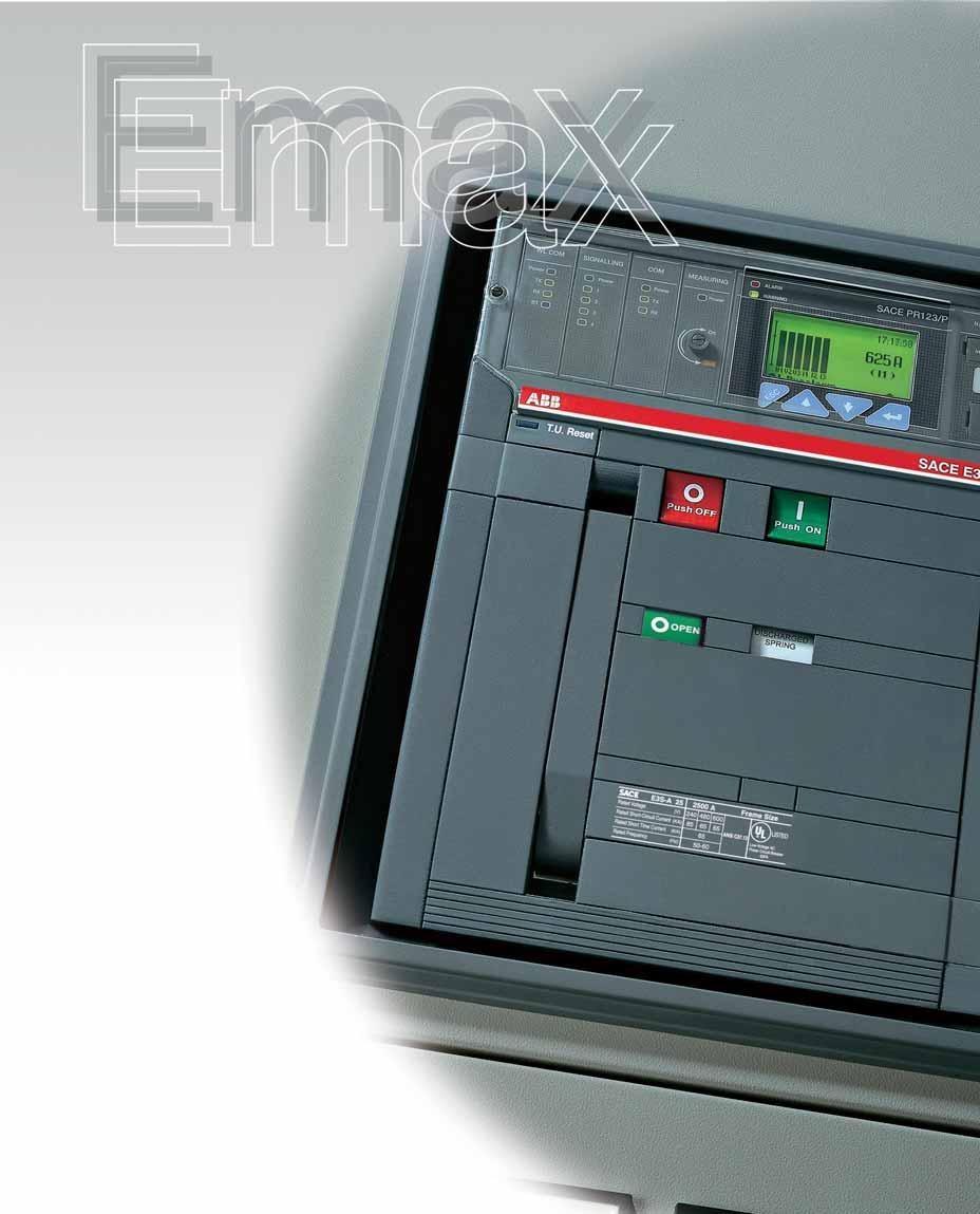
23 Construction characteristics Operating and signaling parts Fixed version 1SDC200022F Caption 1 Trademark and size of circuit breaker 2 PR121, PR122 or PR123 Trip units 3 Pushbutton for manual opening 4 Pushbutton for manual closing 5 Lever to manually charge closing springs 6 Label with electrical characteristics 7 Mechanical device to signal circuit breaker open O and closed I 8 Signal for springs charged or discharged 9 Mechanical indication of trip 10 Key lock in open position 11 Key lock and padlock in racked-in/racked-out position (for draw out version only) 12 Racking-in/racking out device (for draw out version only) 13 Terminal box (for fixed version only) 14 Sliding contacts (for draw out version only) 15 Circuit breaker position indicator: connected/ isolated for test/racked-out (for draw out version only) 14 Draw out version 1SDC200023F0201 Note: Connected refers to the position in which both the power contacts and auxiliary contacts are connected; racked-out is the position in which both the power contacts and auxiliary contacts are disconnected; isolated for test is the position in which the power contacts are disconnected, while the auxiliary contacts are connected /8 ABB

24 Construction characteristics Cradles of draw out circuit breakers The cradles of draw out circuit breakers have shutters for segregating the fixed contacts when the circuit breaker is racked out of the compartment. These can be locked in their closed position using padlock devices. Caption 1 Sheet steel supporting structure 2 Single grounding pliers mounted on the left for E1, E2 and E3, double grounding pliers for E4 and E6 3 Safety shutters 4 Terminal support base 5 Terminals 6 Contacts signaling that the circuit breaker is connected, isolated for test, racked-out 7 Sliding contacts 8 Padlock device for safety shutters (on request) 9 Fixing points (4 for E1, E2, E3 and 6 for E4, E6) SDC200024F ABB 1 /9
25 Construction characteristics Circuit breaker components SDC200025F b 6a 5b 5a 2 4 Caption 1 Sheet steel supporting structure 2 Current sensor for trip unit 3 Pole group insulating box 4 Horizontal rear terminals 5a Plates for main fixed contacts 5b Plates for fixed arcing contacts 6a Plates for main moving contacts 6b Plates for moving arcing contacts 7 Arcing chamber 8 Terminal box for fixed version - Sliding contacts for draw out version 9 Trip unit 10 Circuit breaker closing and opening control 11 Closing springs Versions: E1 B-A/N-A, E2 B-A/N-A/S-A/H-A, E3 N-A/S-A/H-A/V-A, E4 S-A/H-A/V-A/L-A, E6 H-A/V-A/L-A 1/10 ABB
26 Versions and connections All circuit breakers are available in fixed and draw out, three pole or four-pole versions. Each series of circuit breakers offers terminals made of silverplated copper bars in the same sizes, regardless of the continuous current ratings of the circuit breakers (except for E3). The cradles for draw out circuit breakers are common to each size, regardless of the continuous current rating and interrupting rating of the relative moving parts (except for E3 and E2S). The availability of various types of terminals makes it possible to build switchboards against the wall, or switchboards to be accessed from behind with rear connections. For special installation needs, the circuit breakers may be fitted with various combinations of upper and lower terminals. The following terminals are also available in the IEC version: front for fixed and draw version and flat for draw out version. 1 Fixed circuit breaker 1SDC200028F0201 1SDC200029F0201 1SDC200026F0201 1SDC200027F0201 Horizontal rear terminals Vertical rear terminals Draw out circuit breaker Horizontal rear terminals Vertical rear terminals ABB 1/11

27 Electronic trip units General characteristics 1 The overcurrent protection for AC installations uses three types of electronic trip unit series: PR121, PR122 and PR123. The basic series, PR121, offers the whole set of standard protection functions, complete with a user-friendly interface. It allows discrimination of which fault caused the trip by means of the new led indications. PR122 and PR123 trip units are of new concept modular architecture. It is now possible to have a complete series of protections, accurate measurements, signaling or dialogue functions, designed and customisable for all application requirements. The protection system consists of: 3 or 4 new generation current sensors (Rogowski coil); external current sensors (i.e. for external neutral, residual current or source ground return protection); a protection unit selected among PR121/P, PR122/P or PR123/P with optional communication module via Modbus or Fieldbus plug network (PR122/P and PR123/P only), as well as via a wireless connection; an opening solenoid, which acts directly on the circuit breaker operating mechanism (supplied with the protection unit). 1SDC200030F0201 1/12 ABB
28 Electronic trip units UL Versions available General characteristics of the electronic trip units: operation without the need for an external power supply microprocessor technology high precision true R.M.S. measurements of the current values trip cause indication and trip data recording interchangeability among all types of trip units setting for neutral configurable: OFF-50%-100%-200% of phase setting for circuit breakers E1, E2, E3 and E4/f, E6/f full-size versions, and E4-E6 with external neutral protection; OFF-50% for standard E4 and E6. The main performance features of the trip units are listed below. 1 SACE PR121 Protection PR121/P PR121/P PR121/P SACE PR122 PR122/P PR122/P PR122/P Protection For all versions U OT M New modules available: Measuring opt. UV OV RV RP UF OF Communication Signaling Bluetooth (wireless link) opt. opt. opt. SACE PR123 Protection PR123/P For all versions PR123/P OT D U UV OV RV RP M UF OF New modules available: Communication opt. Signaling Bluetooth (wireless link) opt. opt. ABB 1/13
29 Electronic trip units UL Versions available 1 Features Protection functions D U OT UV OV RV RP M UF OF PR121 PR122 PR123 Protection against overload with inverse long time-delay trip Selective protection against short circuit inverse or definite short time-delay trip Second selective protection against short circuit inverse or definite short time-delay trip Protection against instantaneous short circuit with adjustable trip current threshold Protection against ground fault residual source ground return Protection against directional short circuit with adjustable time-delay Protection against phase unbalance Protection against overtemperature (check) Undervoltage protection opt. (1) Overvoltage protection opt. (1) Residual voltage protection opt. (1) Reverse active power protection opt. (1) Thermal memory for functions L and S Underfrequency protection opt. (1) Overfrequency protection opt. (1) Measurements Currents (phases, neutral, ground fault) Voltage (phase-phase, phase-neutral, residual) opt. (1) Power (active, reactive, apparent) opt. (1) Power factor opt. (1) Frequency and peak factor opt. (1) Energy (active, reactive, apparent, meter) opt. (1) Harmonics analisys (display of wave forms and harmonics module) Event marking and maintenance data Event marking with the instant it occurred opt. (2) Chronological event storage opt. (2) Electrical operations counter and contact wear Communication with supervision system and centralised control (IEC only) Remote setting of the protection functions parameter, unit configuration, communication opt. (3) opt. (3) Transmission of measurements, states and alarms from circuit breaker to system opt. (3) opt. (3) Transmission of events and maintenance data from circuit breaker to system opt. (3) opt. (3) Watchdog Alarm and trip for release overtemperature Check of trip status Interface with the user Presetting by means of dip switches Presetting by means of keys and LCD viewer Alarm signals for functions L, S, I and G Alarm signal of one of the following protections: undervoltage, overvoltage, residual voltage, reverse power, phase unbalance, overtemperature opt. (1) Complete management of pre-alarms and alarms for all the self-control protection functions Enabling password for use with consultation in READ mode or consultation and setting in EDIT mode Load control Load connection and disconnection according to the current passing through the circuit breaker Zone discrimination Can be activated for protection functions S, G and (PR123 only) D (1) with PR120/V; (2) with BT030 communication unit; (3) with PR120/D-M. 1/14 ABB
30 Electronic trip units Rating plugs Rating plugs Type of circuit breaker Rated current Iu In [A] E1B-A E2B-A 1600 E2N-A E2S-A E2H-A E3N-A E3S-A E3H-A E3V-A E4S-A E4H-A E4V-A E4L-A E6H-A E6V-A E6L-A ABB 1/15


, CEI EN")

 nr.")


31 Compliance with Standards Standards, approvals, certifications and company quality System The Emax power circuit breakers conform with the ANSI C37.13, C37.16, C37.17 and C37.50 Standards and are UL 1066 certified. The UL 1066 certification allows Emax to be used in UL 1558 switchgears, gear UL891 Low Voltage switchboards and CSA C22.2 no. 31 Switchgear Assemblies. 1 All the Emax circuit breakers and their accessories are also available in the versions complying with the International IEC 60947, EN (harmonized in 28 CENELEC countries), CEI EN and IEC Standards and conform with the following EC directives: Note: Contact ABB for a list of approved types of circuit breakers, approved performance data and the corresponding validity Low Voltage Directive (LVD) nr. 73/23 EEC Electromagnetic Compatibility Directive (EMC) nr. 89/336 EEC. The main versions of the equipment are approved by the following Shipping Registries: ABS (American Bureau of Shipping) RINA (Italian Shipping Register) Det Norske Veritas Bureau Veritas Germanischer Lloyd Lloyd s Register of Shipping Polskj Reiestr Statkow Gost NK Certification of conformity with the aforementioned product Standards is carried out in compliance with the EN European Standard by the Italian certification body ACAE (Associazione per la Certificazione delle Apparecchiature Elettriche - Association for Certification of Electrical Equipment), recognized by the European organization LOVAG (Low Voltage Agreement Group). 1/16 ABB


32 Compliance with Standards A design dedicated to quality and respect for the environment Quality has always been the leading commitment of ABB. This commitment involves every function of the company, and has allowed us to achieve prestigious recognition internationally. The company s Quality System is certified by RINA, one of the most prestigious international certification bodies, and complies with ISO 9001 Standards; the ABB test facility is accredited by SINAL; the plants in Frosinone, Patrica, Vittuone and Garbagnate Monastero are also certified in compliance with OHSAS Standards for health and safety in the workplace. ABB SACE, Italy s first industrial company in the electro-mechanical sector to achieve this, has been able to reduce its raw material consumption and machining scrap by 20% thanks to an ecology-orientated revision of its manufacturing process. All of the company s Divisions are involved in streamlining raw material and energy consumption, preventing pollution, limiting noise pollution and reducing scrap resulting from manufacturing processes, as well as to carrying out periodic environmental audits of its leading suppliers. 1 1SDC200039F0001 ABB is committed to environmental protection, as is also evidenced by the Life Cycle Assessments (LCA) of products carried out at the Research Center: this means assessment and improvement of the environmental performance of products throughout their life cycle are included right from the initial design engineering stage. The materials, processes and packaging used are chosen with a view to optimizing the actual environmental impact of each product, including its energy efficiency and recyclability. ABB 1/17
33

34 Installation in switchboards and switchgears Modular design To allow easier installation and integration in Low Voltage switchgears and switchboards, the Emax series have been built with a modular design criteria, thanks to the same depth and height for all the sizes, as well as a significant reduction in their overall installation dimensions. The front shield of the circuit breaker is identical for the entire series. This simplifies the construction of the switchboard doors since only one type of cut out is required and makes the front of the switchboards and switchgears the same for all sizes. 2 1SDC200044F0201 2/2 ABB


35 Installation in switchboards and switchgears Selecting the type of circuit breaker Number of poles The choice of the number of poles for circuit breakers that simultaneously provide switching, protection and isolation functions in three-phase installations depends on the type of electrical system and the type of utilization or, more generally, whether it includes neutral. 2 Fixed or draw out version The fixed version of the circuit breaker is more compact in size than the draw out version. It is recommended for installations that can tolerate service interruptions in the event of faults or routine maintenance. The draw out version of the circuit breaker is recommended for: applications that can only tolerate brief interruptions due to faults or routine maintenance. dual lines, one of which is a standby for the other, with a single circuit breaker for each pair. 1SDC200045F0201 ABB 2/3
36 Installation in switchboards and switchgears Selecting the type of circuit breaker Connecting the main circuit breaker circuits When designing switchboards, one must always keep in mind the problem of making the most rational connections between the circuit breaker and main busbar system. The Emax series offers a range of options to satisfy different circuit breaker connection requirements. The figures below provide some indications for terminal selection. 2 Horizontal rear terminals Vertical rear terminals For switchboards with access from the rear For switchboards with access from the rear 2/4 ABB
37 Note The values indicated refer to balanced loads, with a current equal to the circuit breaker rating, and automatic circuit breakers. Power losses The following table provides the power loss for fixed and draw out circuit breakers. Power loss Circuit breaker Iu Fixed Withdrawable 3/4 poles 3/4 poles [A] [W] [W] E1B-A/N-A E2B-A/N-A/S-A/H-A E3N-A/S-A/H-A/V-A E4S-A/H-A/V-A E4L-A E6H-A/V-A E6L-A Derating in altitude Emax power circuit breakers do not undergo any changes in their rated performance up to an altitude of 6600 ft (2000 meters). As the altitude increases the atmospheric properties alter in terms of composition, dielectric capacity, cooling power and pressure. The performance of the circuit breakers therefore undergoes derating which can be measured through the variation in significant parameters, such as the maximum rated operating voltage and the rated uninterrupted current. The table below shows the values in relation to altitude. Altitude [ft] < [m] Rated service voltage Ue [V] Continuous current rating In [A] In 0.98xIn 0.93xIn 0.90xIn ABB 2/5

38 Installations Contents Installation in switchboards and switchgears Modular design... 2/2 Selecting the type of circuit breaker... 2/3 2 ABB 2/1

39
... 3/34 PR120/D-BT Wireless Communication Module... 3/34 BT030 Communication unit.")
40 Electronic trip units and related accessories Contents Trip units and trip curves PR121/P... 3/2 PR122/P... 3/9 PR123/P... 3/23 Accessories for trip units PR120/K Internal Module... 3/33 3 PR120/V Measurement Module... 3/33 PR120/D-M Communication Module (IEC only)... 3/34 PR120/D-BT Wireless Communication Module... 3/34 BT030 Communication unit... 3/34 PR030/B power supply unit... 3/34 Interface from front of HMI030 panel... 3/34 PR010/T configuration test unit... 3/35 Communication devices PR021/K signaling unit... 3/36 SD-Pocket... 3/38 ABB 3/1

41 Trip units and trip curves PR121/P Characteristics PR121/P is the new basic and complete trip unit for the Emax series. The complete range of protection functions together with the wide combination of thresholds and trip times offered make it suitable for protecting a wide range of alternating current installation. In addition to protection functions the unit is provided with multifunction LED indicators. Furthermore, PR121/P allows connection to external devices enhancing its advanced characteristics like remote signaling and monitoring, or remote supervision display SDC200105F Caption 1 LED signaling Alarm for protection function L 2 LED signaling Alarm for protection function S 3 LED signaling Alarm for protection function I 4 LED signaling Alarm for protection function G 5 DIP switches for fine setting current threshold l1 6 DIP switches for main setting current threshold l1 7 DIP switches for setting current threshold I2 8 DIP switches for setting current threshold l3 9 DIP switches for setting current threshold l4 10 DIP switches for setting trip time t1 (type of curve) 11 DIP switches for setting trip time t2 (type of curve) 12 DIP switches for setting trip time t4 (type of curve) 13 Indication of the DIP switch position for network frequency 14 Indication of the DIP switch position for Neutral protection setting 15 Rating plug 16 Indication of the DIP switch positions for the various current thresholds values l1 17 Indication of the DIP switch positions for the various current threshold values l2 18 Indication of the DIP switch positions for the various current threshold values l3 19 Indication of the DIP switch positions for the various current threshold values l4 20 Indication of DIP switch positions for the various time settings t1 21 Indication of DIP switch positions for the various time settings t2 22 Indication of DIP switch positions for the various time settings t4 23 DIP switch for setting network frequency and neutral protection setting 24 Trip cause indication and trip test pushbutton 25 Test connector for connecting or testing the trip unit through an external device (PR030/B battery unit, BT030 wireless communication unit and PR010/T unit) 26 Serial number of protection trip unit 3 /2 ABB
42 Operation and protection functions Protection functions The PR121 trip unit offers the following protection functions: overload (L) selective short circuit (S) instantaneous short circuit (I) ground fault G). Overload (L) The long time-delay trip protection L is type l 2 t = k; 25 current thresholds and 8 curves are available. Each curve is identified by the trip time in relation to the current l = 3 x l1 (l1 = set threshold). Selective short circuit (S) The selective short circuit protection S can be set with two different types of curves with a trip time independent of the current (t = k) or with a constant specific let-through energy (t = k/l 2 ). 15 current thresholds and 4 curves are available, allowing a fine setting. Each curve is identified as follows: for curves t = k by the trip time for l > I2 for curves t = k/l 2 by the trip time for l = 10xln (ln = rated current of the circuit breaker). The function can be excluded by setting the DIP switch combination to OFF. Adjustable instantaneous short circuit (l) The protection I offers 15 trip thresholds and can be excluded (dip switches in OFF position). Ground fault (G) The ground fault protection G (which can be excluded) offers 7 current thresholds and 3 curves. Each curve is identified by the time t4 in relation to current I4. As per S protection the trip time can be chosen independent of the current (t = k) or with a constant specific let-through energy (t = k/l 2 ). Note: the maximum value for the function G is 1200 A and this function is repressed for fault current values higher than the values shown in table below. 3 I4 threshold Repression threshold I4 < 0.5 In 4 In 0.5 In I4 < 0.8 In 6 In I4 ³ 0.8 In 8 In In = rated current of the rating plug t t t = k I 2 t = k I 2 t = k t = k I 1SDC200116F0001 I 1SDC200117F0001 ABB 3 /3
43 Trip units and trip curves PR121/P User interface The trip unit can be set by using the dip switches on the front. Up to four LEDs (according to the version) are also available for signaling. These LEDs (one for each protection) are active when: a protection is timing. For protection L the prealarm status is also shown; a protection has tripped (the corresponding LED is activated by pressing the Info/Test pushbutton); a failure in connection of a current sensor or in the opening solenoid is detected. The indication is active when the unit is powered (through current sensors or an auxiliary power supply) wrong rating plug for the circuit breaker. The protection tripped indication works even with the circuit breaker open, without the need for any internal or external auxiliary power supply. This information is available for 48 hours of inactivity after the trip and is still available after reclosing. If the query is made more than 48 hours later it is sufficient to connect a PR030/B battery unit, PR010/T, or a BT030 wireless communication unit. Communication 3 By means of the BT030 wireless communication unit, PR121/P can be connected to a pocket PC (PDA) or to a personal computer, extending the range of information available for the user. In fact, by means of ABB s SD-Pocket communication software, it is possible to read the values of the currents flowing through the circuit breaker, the value of the last 20 interrupted currents, and the protection settings. PR121 can also be connected to the optional external PR021/K signaling unit, for the remote signaling of protections alarms and trips, and to HMI030, for the remote user interfacing. Setting the neutral Protection of the neutral can be set at 50%, 100% or 200% of the phase currents. Settings above 50% can be selected for E1-E2-E3-E4/f and E6/f. In particular, setting the neutral at 200% of phase current requires protection L to be set at 0.5In in order to respect the current-carrying capacity of the circuit breaker. The user can also switch the neutral protection OFF. When threepoles circuit breakers with external neutral current sensor are used, a setting above 100% for the neutral does not require any reduction in the L setting. Test Function A trip test can be carried out using the info/test pushbutton and the PR030/B battery unit (or BT030). The PR121/P electronic trip unit can be tested by using the PR010/T test and configuration unit by connecting it to the TEST connector. 3 /4 ABB


44 Versions available The following versions are available: PR121/P LI 1SDC200106F PR121/P LSI PR121/P LSIG 1SDC200105F0001 1SDC200107F0001 ABB 3 /5
45 Trip units and trip curves PR121/P Protection functions and setting values - PR121 Function Trip threshold Trip time Can be excluded Relation t=f(i) 3 Overload I1= At current I = 3 x I1 t=k/i 2 protection t1 = s (1) x In Tolerance (2) Release between 1.05 and 1.2 x I1 ± 10% Isc (4) 4 x In ± 20% Isc (4) > 4 x In Selective short-circuit I2= At current I > I2 t=k protection x In t2 = s Tolerance (2) ± 7% Isc (4) 4 x In The best of the given: ± 10% Isc (4) > 4 x In ± 10% or ± 40 ms I2= At current I = 10 x In t=k/i x In t2 = s Tolerance (2) ± 7% Isc (4) 4 x In ± 15% Isc (4) 4 x In ± 10% Isc (4) > 4 x In ± 20% Isc (4) > 4 x In Instantaneous I3= Instantaneous t=k short-circuit protection x In Tolerance (2) ± 10% 30 ms Ground fault I4= At current I = 4 x I4 t=k/i 2 protection x In (3) t4 = s Tolerance (2) ± 7% ± 15% I4= At current I > I4 t=k x In (3) t4 = s Tolerance (2) ± 7% The best of the given: ± 10% or ± 40 ms (1) The minimum trip time is 1 s, regardless of the type of curve set (self-protection) (2) These tolerances are valid with the following hypotheses: - trip unit self supplied when running (without start-up) - two-phase or three-phase power supply - trip time set ³ 100 ms (3) The maximum value for G protection is 1200 A (4) Short circuit current In all cases not covered by the above hypotheses, the following tolerance values are valid: Trip threshold Trip time L Release between 1.05 and 1.25 x I1 ± 20% S ± 10% ± 20% I ± 15% 60ms G ± 15% ± 20% Power supply The unit does not require an external power supply either for protection functions or for alarm signaling functions. It is self-supplied by means of the current sensors installed on the circuit breaker. For it to operate, it is sufficient for at least one phase to be loaded at 100A of the rated current of the current sensors (In). An external power supply can be connected in order to activate additional features, and in particular for connection to external devices: HMI030 and PR021/K. PR121/P Auxiliary power 24 V DC ± 20% supply (galvanically insulated) Maximum ripple 5% Inrush 24V ~10 A for 5 ms Rated 24V ~2 W 3 /6 ABB
46 Functions L-I 3 1SDC200049F0201 Functions L-S-I t = k I 2 Threshold and trip times tolerances... page 3/6 1SDC200050F0201 ABB 3 /7
47 Trip units and trip curves PR121/P Functions L-S-I t = k 3 1SDC200051F0201 Function G Note: The maximum value for G protection is 1200 A t = k I 2 t = k 1SDC200052F0201 Threshold and trip times tolerances... page 3/6 3 /8 ABB

48 Trip units and trip curves PR122/P Characteristics The PR122 trip unit is an advanced and flexible protection system based on a state-of-the art microprocessor and DSP technology. Fitted with the optional internal PR120/D-M dialogue unit, PR122/P turns into an intelligent protection, measurement and communication device, based on the Modbus protocol. By means of the PR120/D-M, PR122/P can also be connected to the ABB EP010 Fieldbus plug adapter, which makes it possible to choose among several different networks, such as Profibus and DeviceNet (IEC only). The new PR122/P is the result of ABB s experience in designing trip units. The exhaustive range of settings makes this trip unit ideal for general use in any type of installation, from distribution to the protection of motors, transformers, drives and generators. Access to information and programming using a keyboard and graphic liquid crystal display is extremely simple and intuitive. The interface is now common to PR122/P and PR123/P in order to give to the user maximum ease of use. An integrated ammeter and many other additional features are provided over and above the protection functions. These additional functions can be further increased with addition on board of the dialogue, signaling, measurement, and wireless communication units. Functions S and G can operate with a time delay independent of the current (t = k) or with an inverse time delay (constant specific let-through energy: I 2 t = k), as required. Protection against ground faults can also be obtained by connecting the PR122 trip unit to an external toroid located on the conductor that connects the transformer star centre to ground (homopolar toroid). All the thresholds and trip curve delays of the protection functions are stored in special memories which retain the information even when no power is supplied SDC200108F Caption 1 LED Warning indicator 2 Alarm LED 3 Rear-lit graphic display 4 Cursor UP button 5 Cursor DOWN button 6 Test connector for connecting or testing the trip unit by means of an external device (PR030/B battery unit, BT030 wireless communication unit and PR010/T unit) 7 ENTER button to confirm data or change pages 8 Button to exit submenus or cancel operations (ESC) 9 Rating plug 10 Serial number of protection trip unit ABB 3 /9
49 Trip units and trip curves PR122/P Operation, protection functions and self-test Basic Protection functions 100% for E1, E2, E3, E4/f and rents of certain loads (motors, 3 The PR122 trip unit offers the following protection functions (according to the version): overload (L) selective short circuit (S) instantaneous short circuit (I) ground fault (G) phase unbalance (U) self-protection against overtemperature (OT) thermal memory for functions L and S zone discrimination for functions S and G source ground return with external toroid E6/f. In installations where very high harmonics occur, the resulting current at the neutral can be higher than that of the phases. Therefore it is possible to set the neutral protection at 150% or 200% of the value set for the phases. In this case it is necessary to reduce the setting of protection L accordingly (1). The table below lists the neutral settings for the various possible combinations between type of circuit breaker and the threshold I1 setting. transformers, lamps). The start-up phase lasts from 100 ms to 1.5 s, in steps of 0.05 s. It is automatically recognized by the PR122 trip unit as follows: when the circuit breaker closes with the trip unit selfsupplied; when the peak value of the maximum current exceeds 0.1 x In. A new start-up becomes possible after the current has fallen below the threshold of 0.1 x In, if the trip unit is supplied from an external source. Setting the neutral Start-up function In PR122/P, and PR123/P as The start-up function allows well, the neutral protection is protections S, I and G to oper- Note: (1) When three-pole circuit breakers with external neutral current sensor are used, a setting above 100% for the neutral does not require any reduction in the L setting up to Iu N. 50% of the value set for phase protection in the standard version. The neutral protection can be excluded or set to ate with higher trip thresholds during the start-up phase. This avoids untimely tripping caused by the high inrush cur- Adjustable neutral protection settings Threshold I1 settings (overload protection) Circuit breaker model 0.4 I < I < I1 1(*) E1B-N % % % E2B-N-S-L % % % E3N-S-H-V-L % % % E4S-H-V-L % 0-50% 0-50% E4S/f-H/f % % % E6H-V-L % 0-50% 0-50% E6H/f % % % (*) The setting I1 =1 indicates the maximum overload protection setting. The actual maximum setting allowable must take into account any derating based on temperature, the terminals used and the altitude (see the Installations chapter) 3/10 ABB
50 Phase unbalance protection U Protection function U against phase unbalance is used in those situations requiring particularly precise control over missing and/or unbalanced phase currents, giving only pre-alarm signaling. This function can be excluded. Zone 3 Zone 2 Zone 1 Protection against over-temperature The range of PR122 trip units allows the presence of abnormal temperatures, which could cause temporary or continuous malfunctions of the microprocessor, to be signalled to the user. The user has the following signals or commands available: lighting up of the Warning LED when the temperature is higher than 158 F / 70 C (temperature at which the microprocessor is still able to operate correctly) lighting up of the Alarm LED when the temperature is higher than 185 F / 85 C (temperature above which the microprocessor can no longer guarantee correct operation) and, when decided during the unit configuration stage, simultaneous opening of the circuit breaker with indication of the trip directly on the display, as for the other protections. Zone discrimination for protections S and G Zone discrimination is one of the most advanced methods for making co-ordination of the protections: by using this protection philosophy, it is possible to reduce the trip times of the protection closest to the fault in relation to the times foreseen by time discrimination, of which zone discrimination is an evolution. Zone discrimination is applicable to protection functions S and G, even contemporarily and is available as standard on the PR122. The word zone is used to refer to the part of an installation between two circuit breakers in series (see picture beside). Protection is provided by connecting all of the zone discrimination outputs of the trip units belonging to the same zone together and taking this signal to the zone discrimination input of the trip unit immediately to the supply side. Each circuit breaker that detects a fault communicates this to the circuit breaker on the supply side using a simple connection wire. Therefore the fault zone is the zone immediately to the load side of the circuit breaker that detects the fault, but does not receive any communication from those on the load side. This circuit breaker opens without waiting for the set time-delay. ABB provides important calculation tools to facilitate the work of designers in coordinating protection devices, including the Slide rule kits, DOCWin and CAT software packages and updated coordination charts. The zone discrimination function S and G can be activated or 1SDC200186F0001 deactivated using the keyboard. 3 ABB 3/11
51 Trip units and trip curves PR122/P Self-diagnosis The PR122 range of trip units contains an electronic circuit which periodically checks the continuity of internal connections (opening solenoid or each current sensor, including the Source Ground Return when present). In the case of a malfunction an alarm message appears directly on the display. The alarm is highlighted by the alarm LED as well. Test Functions Once enabled from the menu, the info/test pushbutton on the front of the trip unit allows correct operation of the chain consisting of the microprocessor, opening solenoid and circuit breaker tripping mechanism to be checked. The control menu also includes the option of testing correct operation of the display, signaling LEDs, and electrical contacts of the PR120/K trip unit. By means of the front multi-pin connector it is possible to apply a PR010/T Test unit which allows the functions of the PR121, PR122 and PR123 ranges of trip units to be tested and checked. 3 User interface The human-machine interface (HMI) of the device is made up of a wide graphic display, LEDs, and browsing pushbuttons. The interface is designed to provide maximum simplicity. The language can be selected from among five available options: English, Italian, German, French and Spanish. As in the previous generation of trip units, a password system is used to manage the Read or Edit modes. The default password, 0001, can be modified by the user. The protection parameters (curves and trip thresholds) can be set directly via the HMI of the device. The parameters can only be changed when the trip unit is operating in Edit mode, but the information available and the parameter settings can be checked at any time in Read mode. When a communication device (internal PR120/D-M and PR120/D-BT modules or external BT030 device) is connected, it is possible to set parameters simply by downloading them into the unit (by using the SD-Pocket software and a PDA or a notebook for PR120/D-BT and BT030). Parameterisation can then be carried out quickly and automatically in an error-free way by transferring data directly from DocWin. Indicator LEDs LEDs on the front panel of the trip unit are used to indicate all the pre-alarms ( WARNING ) and alarms ( ALARM ). A message on the display always explicitly indicates the type of event concerned. Example of events indicated by the WARNING LED: unbalance between phases; pre-alarm for overload (L1>90%); first temperature threshold exceeded (158 F / 70 C); contact wear beyond 80%; phase rotation reversed (with optional PR120/V) Example of events indicated by the ALARM LED: overload (may begin from 1.05xl1<I<1.3xl1, in accordance with the standard IEC ); timing of function L; timing of function S; timing of function G; second temperature threshold exceeded (185 F / 85 C); contact wear 100%; timing of Reverse Power flow protection (with optional PR120/V); 3/12 ABB
52 Data logger By default PR122/P, as well as PR123, is provided with the Data Logger function, that automatically records in a wide memory buffer the instantaneous values of all the currents and voltages. Data can be easily downloaded from the unit by means of SD-Pocket or TestBus2 applications using a Bluetooth port and can be transferred to any personal computer for elaboration. The function freezes the recording whenever a trip occurs, so that a detailed analysis of faults can be easily performed. SD-Pocket and TestBus2 allow also reading and downloading of all the others trip information. Number of channels: 8 Maximum sampling rate: 4800 Hz Maximum sampling time: 27 s ( sampling rate 600 Hz) 64 events tracking Trip information and opening data In case a trip occurs PR122/P and PR123/P store all the needed information: Protection tripped Opening data (current) Time stamp (guaranteed with auxiliary supply or self-supply with power failure no longer than 48h) By pushing the info/test pushbutton the trip unit shows all these data directly on display. No auxiliary power supply is needed. The information is available to user for 48 hours with the circuit breaker open or without current flowing. The information of the latest 20 trips are stored in memory. If the information can be furthermore retrieved more than 48 hours later, it is sufficient to connect a PR030/B battery unit or a BT030 wireless communication unit. 3 Load control Load control makes it possible to engage/disengage individual loads on the load side before the overload protection L is tripped, thereby avoiding unnecessary trips of the circuit breaker on the supply side. This is done by means of contactors or switches (externally wired to the trip unit), controlled by the PR122 by PR120/K internal contacts, or by PR021/K unit. Two different Load Control schemes can be implemented: disconnection of two separate loads, with different current thresholds connection and disconnection of a load, with hysteresis Current thresholds and trip times are smaller than those available for selection with protection L, so that load control can be used to prevent overload tripping. Internal PR120/K or external PR021/K accessory unit is required for Load Control. The function is only active when an auxiliary power supply is present. ABB 3/13

53 Trip units and trip curves PR122/P PR120/V Measurement Module 1SDC200114F0001 This optional internal module, installed in PR122 (standard in PR123), allows the trip unit to measure the phase and neutral voltages and to process them in order to achieve a series of features, in terms of protection and measurement. PR120/V does not normally require any external connection or Voltage Transformer, since it is connected internally to the lower terminals of Emax. When necessary, the connection of voltage pick-ups can be moved to any other points (i.e. upper terminals), by using the alternative connection located in the terminal box. The module is provided with a sealable switch for the dielectric test. PR120/V is able to energize the PR122 when line voltage input is above 85V. The use of Voltage Transformers is mandatory for rated voltages higher than 690V. Voltage transformers shall have burdens equal to 10VA and accuracy class 0.5 or better. 3 Additional Protections with PR120/V: Undervoltage (UV) protection Overvoltage (OV) protection Residual voltage (RV) protection Reverse power (RP) protection Underfrequency (UF) protection Overfrequency (OF) protection Phase sequence (alarm only) All the above indicated protections can be excluded, although it is possible to leave only the alarm active when required. With the circuit breaker closed, these protections also operate when the trip unit is selfsupplied. With the circuit breaker open, they operate when the auxiliary power supply (24V DC or PR120/V) is present: in this case the trip unit will indicate the ALARM status. Voltage protections UV, OV, RV The residual voltage protection RV identifies interruptions of the neutral (or of the grounding conductor in systems with grounding neutral) and faults that shift the star centre in systems with insulated neutral (e.g. large ground faults). The star centre shift is calculated as a vectorial sum of the phase voltages. Reverse power protection RP Reverse power protection is especially suitable for protecting large machines such as motors and generators. The PR122 with the PR120/V module can analyse the direction of the active power and open the circuit breaker if the direction is opposite to that of normal operation. The reverse power threshold and the trip time are adjustable. Frequency protections UF, OF The frequency protections detect the variation of network frequency above adjustable thresholds, generating an alarm or opening the circuit breaker. It is a protection typically needed in an isolated network, i.e. powered by a genset. 3/14 ABB

54 Measurement function The current measurement function (ammeter) is present on all versions of the PR122 unit. The display shows histograms showing the currents of the three phases and neutral on the main page. Furthermore, the most loaded phase current is indicated in numerical format. Ground fault current, where applicable, is shown on a dedicated page. The latter current value takes on two different meanings depending on whether the external toroidal transformer for the Source Ground Return function or the internal transformer (residual type) is connected. The ammeter can operate either with self-supply or with an auxiliary power supply voltage. In the latter case the display is rear-lit and the ammeter is active even at current levels lower than 160A. Accuracy of the ammeter measurement chain (current sensor plus ammeter) is no more than 1.5% in the 30% - 120% current interval of In. Currents: three phases (L1, L2, L3), neutral (Ne) and ground fault; Instantaneous values of currents during a period of time (data logger); Maintenance: number of operations, percentage of contact wear, opening data storage (last 20 trips and 20 events). 3 When the optional PR120/V is connected the following additional measurement function are present: Voltage: phase-phase, phase-neutral and residual voltage Instantaneous values of voltages during a period of time (data logger); Power: active, reactive and apparent Power factor Frequency and peak factor Energy: active, reactive, apparent, counter Versions available The following versions are available: PR122/P LI-LSI-LSIG 1SDC200113F0001 ABB 3/15
55 Trip units and trip curves PR122/P Protection functions and setting values - PR122 Function Trip Threshold Trip Time Can be Relation Thermal Zone threshold steps Time Step excluded t=f(i) memory discrimination 3 OT U Overload I1= x In 0.01 x In At current I= 3 x I1 3 s (1) t=k/i 2 protection t1= 3 s s Tolerance (2) Release between ± 10% Isc (5) 4 x In 1.05 and 1.2 x I1 ± 20% Isc (5) > 4 x In Selective short At current I > I2 circuit protection I2= x In 0.1 x In t2= 0.05 s.0.4 s (2) 0.01 s t=k Tolerance (2) The best of the two given: ± 7% Isc (5) 4 x In ± 10% or ± 40 ms ± 10% Isc (5) > 4 x In At current I= 10 x In I2= x In 0.1 x In t2= 0.05 s.0.4 s 0.01 s t=k/i 2 Tolerance (2) ± 7% Isc (5) 4 x In ± 15% Isc (5) 4 x In ± 10% Isc (5) > 4 x In ± 20% Isc (5) > 4 x In Instantaneous short circuit protection I3= x In 0.1 x In Instantaneous t=k Tolerance (2) ± 10% 30 ms Ground fault At current I > Iu protection I4= x In (3) 0.02 x In t4= 0.1 s..0.4 s 0.05 s t=k Tolerance (2) ± 7% The best of the two given: ± 10% or ± 40 ms I4= x In (3) 0.02 x In t4= 0.1 s..0.4 s (with I= 4 x I4) 0.05 s t=k/i 2 Tolerance (2) ± 7% ± 15% Protection against overtemperature may not be set Instantaneous temp=k Phase unbalance protection I6= 5%.90% 5% t4= 0.5 s..60 s 0.5 s t=k Tolerance (2) ± 10% The best of the two given: ± 20% or ± 100 ms (1) The minimum trip value is 1 s, regardless of the type of curve set (self-protection) (2) These tolerances are valid with the following hypotheses: - relay self-supplied when running and/or auxiliary power supply (without start-up) - two-phase or three-phase power supply - trip time set ³ 100 ms (3) The maximum value for G protection is 1200 A (4) Non intervention time (5) Short circuit current In all cases not covered by the above hypotheses, the following tolerance values are valid: Trip threshold Trip time L Release between 1.05 and 1.25 x I1 ± 20% S ± 10% ± 20% I ± 15% 60ms G ± 15% ± 20% Others ± 20% 3/16 ABB
56 Additional Protection functions and setting values - PR122 with PR120/V Function Trip Threshold Trip Time Can be Relation Thermal Zone threshold steps Time Step excluded t=f(i) memory discrimination UV OV RV RP UF OF Undervoltage U8= x Un 0.01 x In At current U < U8 0.1 s t=k protection t8= 0.1 s...5 s Tolerance (1) The best of the two given: ± 5% ± 20% or ± 100 ms Overvoltage U9= x Un 0.01 x In At current U > U9 0.1 s t=k protection t9= 0.1 s...5 s Tolerance (1) The best of the two given: ± 5% ± 20% or ± 100 ms Residual voltage U10= x Un 0.05 x Un At current U > U s t=k protection t10= 0.5 s...30 s Tolerance (1) The best of the two given: ± 5% ± 10% or ± 100 ms Reverse power P11= x Pn0.02 x Pn At current P < P s t=k protection t11= 0.5 s...25 s Tolerance (1) The best of the two given: ± 5% ± 10% or ± 100 ms Underfrequency f12= x fn 0.01 x fn At current f < f s t=k protection t9= 0.5 s...3 s Tolerance (1) The best of the two given: ± 5% ± 10% or ± 100 ms Overfrequency f13= x fn 0.01 x fn At current f > f s t=k protection t10= 0.5 s...3 s Tolerance (1) The best of the two given: ± 5% ± 10% or ± 100 ms 3 (1) These tolerances are valid with the following hypotheses: - relay self-supplied when running and/or auxiliary power supply (without start-up) - two-phase or three-phase power supply Power supply The PR122 trip unit does not normally require any external power supplies, being self-supplied from the current sensors (CS): to activate the protection and ammeter functions, it is sufficient for at least one phase to have a current load higher than 100 A. For the display to come on, at least one phase must have a current load higher than 160 A. The unit ensures fully self-supplied operation. When an auxiliary power supply is present, it is also possible to use the unit with the circuit breaker either open or closed with very low current flowing through. It is also possible to use an auxiliary power supply provided by the PR030/B portable battery unit (always supplied), which allows the protection functions to be set when the trip unit is not selfsupplied. PR122/P stores and shows all the information needed after a trip (protection tripped, trip current, time, date). No auxiliary supply is required for this functionality. PR122/P PR120/D-M PR120/K PR120/D-BT Note: PR120/V can give power supply to the trip unit when at least one line voltage is equal or higher to 85V RMS. Auxiliary power supply 24 V DC ± 20% from PR122/PR123 from PR122/PR123 from PR122/PR123 (galvanically insulated) Maximum ripple 5% Inrush 24V ~10 A for 5 ms Rated 24V ~3 W +1 W +1 W +1 W ABB 3/17
57 Trip units and trip curves PR122/P Functions L-I 3 1SDC200054F0201 1SDC200053F0201 Functions L-S-I t = k I 2 Threshold and trip times tolerances... page 3/16 3/18 ABB
58 Functions L-S-I t = k 3 1SDC200055F0201 Function G Note: The maximum value for G protection is 1200 A t = k I 2 t = k 1SDC200056F0201 Threshold and trip times tolerances... page 3/16 ABB 3/19
59 Trip units and trip curves PR122/P Function U U 3 1SDC200057F0201 Function UV UV 1SDC200058F0201 Threshold and trip times tolerances... page 3/16 3/20 ABB
60 Function OV OV 3 1SDC200059F0201 Function RV RV 1SDC200060F0201 Threshold and trip times tolerances... page 3/16 ABB 3/21
61 Trip units and trip curves PR122/P Function RP RP 3 1SDC200061F0201 Threshold and trip times tolerances... page 3/16 3/22 ABB

62 Trip units and trip curves PR123/P Characteristics The PR123 protection trip unit completes the range of trip units available for the Emax family of circuit breakers. It is a high-performance and extraordinarily versatile trip unit, capable of offering a complete set of functions for protection, measurement, signaling, data storage and control of the circuit breaker, and it represents the benchmark in low voltage protection units for circuit breakers. The front interface of the unit, common to PR122/P, is extremely simple thanks to the aid of the liquid crystal graphics display. It can show diagrams, bar graphs, measurements and sine curves for the various electrical values. PR123 integrates all the features offered by PR122/P plus a series of evolute functionalities. As well as PR122 it can be integrated with the additional features provided by internal modules and external accessories SDC200115F Caption 1 LED Warning indicator 2 Alarm LED 3 Rear-lit graphic display 4 Cursor UP button 5 Cursor DOWN button 6 Test connector for connecting or testing the trip unit by means of an external device (PR030/B battery unit, BT030 wireless communication unit and PR010/T unit) 7 ENTER button to confirm data or change pages 8 Button to exit submenus or cancel operations (ESC) 9 Rating plug 10 Serial number of protection trip unit 11 Power LED 12 Disconnector for voltage pickups ABB 3/23
63 Trip units and trip curves PR123/P 3 Protection functions The PR123 trip unit offers the following protection functions: overload (L), selective short circuit (S), instantaneous short circuit (I), ground fault with adjustable delay (G), directional short circuit with adjustable delay (D), phase unbalance (U), protection against over-temperature (OT), load control (K), undervoltage (UV), overvoltage (OV), residual voltage (RV), reverse power (RP), underfrequency (UF), overfrequency (OF), phase sequence (alarm only). In addition to PR122/P features, the following improvements are available: Overload protection L With the PR123 unit, the overload protection L includes the option to adjust the slope of the protection curve. This adjustment allows perfect coordination with fuses or with medium-voltage protection systems. Double selective short-circuit protection S In addition to the standard S protection, PR123/P makes contemporarily available a second time-constant S protection (excludible) that allows two thresholds to be set independently achieving an accurate discrimination even under highly critical conditions. Double ground fault protection G While in PR121/P and PR122/P the user must choose among the implementation of G protection through internal current sensors (calculating the vectorial sum of currents) or external toroid (direct ground fault current measuring), PR123/P offers the exclusive feature of the contemporaneous management of both the configuration, by means of two independent ground fault protections curves. The main application of this characteristic is simultaneous activation of restricted and unrestricted ground fault protection. See chapter 6 for details. Directional short circuit protection with adjustable delay D The protection works in a similar way to the fixed-time protection S, with the added ability to recognize the direction of the phases current during the fault period. With the information about the current direction it is possible to determine whether the fault is on the supply or load side of the circuit breaker. Particularly in ring distribution systems, with this protection you can disconnect just the portion of system where the fault has occurred, whilst keeping the rest of the installation running. If multiple PR122 or PR123 trip units are used, in the same system this protection can be associated with zone discrimination. 3/24 ABB
64 Dual setting of protections PR123/P can store an alternative set of all the protection parameters. This second set (set B) can replace, when needed, the default set (set A) by means of an external command. The command can be given typically when network configuration is modified, like when a parallel of incoming lines is closed or when an emergency source is present in the system, changing load capability and short circuit levels. Note: The directional short circuit protection can be disabled for an adjustable set time (t = k), and can either be self-supplied or use the auxiliary power supply. Directional protection is not available on 400A rating. The set B can be activated by: digital input provided with PR120/K module. For example It can be connected to an auxiliary contact of a bus-tie communication network, through PR120/D-M (i.e. when the changeover is scheduled); directly from user interface of PR123/P an adjustable time internal after closing of the circuit breaker. Zone discrimination function The zone discrimination function allows the fault area to be insulated by opening the circuit breakers closest to the fault, whilst leaving the rest of the installation running. This is done by connecting the trip units together: the trip unit nearest the fault is tripped instantly, sending a block signal to the other trip units affected by the same fault The zone discrimination function can be enabled if the fixed-time curve has been selected and an auxiliary power supply is present. Zone discrimination can be applied with protections S and G or, alternatively, with protection D. 3 Measurement functions The PR123 trip unit provides a complete set of measurements: Currents: three phases (L1, L2, L3), neutral (Ne) and ground fault Voltage: phase-phase, phase-neutral and residual voltage Power: active, reactive and apparent Power factor Frequency and peak factor Energy: active, reactive, apparent, counter Harmonics calculation: up to the 40 th harmonic (waveform and module of the harmonics displayed); up to the 35 th for frequency f = 60Hz Maintenance: number of operations, percentage of contact wear, opening data storage. The PR123 unit is able to provide the pattern of measurements for some values over an adjustable period of time P, such as: mean active power, maximum active power, maximum current, maximum voltage and minimum voltage. The last 24 P periods (adjustable from 5 to 120 min.) are stored in a non-volatile memory and displayed in a bar graph. Other Functions PR123/P integrates all the features (in terms of protection, measurement, signaling and communication) described for PR122/P equipped with PR120/V. ABB 3/25
65 Trip units and trip curves PR123/P Protection functions and setting values - PR123 Function Trip Threshold Trip Time Can be Relation Thermal Zone threshold steps Time Step excluded t=f(i) memory discrimin. 3 D U OT UV OV RV Overload protection At current I= 3 x I1 (6) I1= x In 0.01 x In t1= 3 s s 3 s (1) t=k/i 2 Tolerance (2) Release between ± 10% Isc (5) 4 x In 1.05 and 1.2 x I1 ± 20% Isc (5) > 4 x In At current I= 3 x I1 I1= x In 0.01 x In t1= 3 s s 3 s Tolerance x I1 ± 20% Isc (5) > 5 x I1 (in accordance with IEC ) ± 30% 2xI1 Isc (5) 5 x I1 In Selective short circuit At current I > I2 protection I2= x In 0.1 x In t2= 0.05 s.0.4 s 0.01s t=k Tolerance (2) ± 7% Isc (5) 4 x In The best of the two given: ± 10% Isc (5) > 4 x In ± 10% or ± 40 ms At current I= 10 x In I2= x In 0.1 x In t2= 0.05 s.0.4 s 0.01s t=k/i 2 Tolerance (2) ± 7% Isc (5) 4 x In ± 15% Isc (5) 4 x In ± 10% Isc (5) > 4 x In ± 20% Isc (5) > 4 x In Selective short circuit At current I > I2 protection I2= x In 0.1 x In t2= 0.05 s.0.4 s 0.01s t=k Tolerance (2) ± 7% Isc (5) 4 x In The best of the two given: ± 10% Isc (5) > 4 x In ± 10% or ± 40 ms At current I= 10 x In I2= x In 0.1 x In t2= 0.05 s.0.4 s 0.01s t=k/i 2 Tolerance (2) ± 7% Isc (5) 4 x In ± 15% Isc (5) 4 x In ± 10% Isc (5) > 4 x In ± 20% Isc (5) > 4 x In Instantaneous short circuit protection I3= x In 0.1 x In Instantaneous t=k Tolerance (2) ± 10% 30 ms Ground fault At current I > I4 protection I4= x In (3) 0.02 x In t4= 0.1 s..0.4 s 0.05 s t=k Tolerance (2) The best of the two given: ± 7% ± 10% or ± 40 ms I4= x In (3) 0.02 x In t4= 0.1 s.0.4 s (with I= 4 x I4) 0.05 s t=k/i 2 Tolerance (2) ± 7% ± 15% Directional short At current I > I7 circuit protection I7= x In 0.1 x In t7= 0.20 s..0.8 s 0.01 s t=k Tolerance (2) The best of the two given: ± 10% ± 10% or ± 40 ms Phase unbalance I6= 5%.90% 5% t6= 0.5 s..60 s 0.5 s t=k protection The best of the two given: Tolerance (2) ± 10% ± 20% or ± 100 ms Protection against overtemperature cannot be set Instantaneous temp=k Undervoltage At current U < U8 protection U8= x Un 0.01 x In t8= 0.1 s..5 s 0.1 s t=k Tolerance (2) The best of the two given: ± 5% ± 20% or ± 40 ms Overvoltage At current U > U9 protection U9= x Un 0.01 x In t9= 0.1 s..5 s 0.1 s t=k Tolerance (2) The best of the two given: ± 5% ± 20% or ± 40 ms Residual voltage At current U > U10 protection U10= x Un 0.05 Un t10= 0.5 s..30 s 0.5 s t=k Tolerance (2) The best of the two given: ± 5% ± 10% or ± 100 ms 3/26 ABB
66 Protection functions and setting values - PR123 Function Trip Threshold Trip Time Can be Relation Thermal Zone threshold steps Time Step excluded t=f(i) memory discrimin. RP UF OF Reverse At current P < P11 power P11= x Pn 0.02 Pn t11= 0.5 s..25 s 0.1 s t=k protection The best of the two given: Tolerance (2) ± 10% ± 10% or ± 100 ms Underfrequency At current f < f12 protection f12 = x fn 0.01 fn t9= 0.5 s..3 s 0.1 s t=k Tolerance (2) The best of the two given: ± 5% ± 10% or ± 100 ms Overfrequency At current f > f13 protection f13 = x fn 0.01 fn t10= 0.5 s..3 s 0.1 s t=k Tolerance (2) The best of the two given: ± 5% ± 10% or ± 100 ms (1) The minimum trip value is 1 s, regardless of the type of curve set (self-protection) (2) These tolerances are valid with the following hypotheses: - self-powered relay when running and/or auxiliary power supply (without start-up) - two- or three-phase power supply - trip time set ³ 100 ms (3) The maximum value for G protection is 1200 A (4) Non intervention time (5) Short circuit current (6) In accordance with IEC Standard In all cases not covered by the above hypotheses, the following tolerance values are valid: Trip threshold Trip time L Release between 1.05 and 1.25 x I1 ± 20% S ± 10% ± 20% I ± 15% 60ms G ± 15% ± 20% Others ± 20% 3 Power supply The PR123 trip unit does not normally require any external power supplies, being self-supplied from the current sensors (CS): to activate the protection and ammeter functions, it is sufficient for at least one phase to have a current load higher than 100 A. For the display to come on, at least one phase must have a current load higher than 160 A. The unit ensures fully self-supplied operation. When an auxiliary power supply is present, it is also possible to use the unit with the circuit breaker either open or closed with very low current flowing through. It is also possible to use an auxiliary power supply provided by the PR030/B portable battery unit (always supplied), which allows the protection functions to be set when the trip unit is not selfsupplied. PR123/P stores and shows all the information needed after a trip (protection tripped, trip current, time, date). No auxiliary supply is required for this functionality. PR123/P PR120/D-M PR120/K PR120/D-BT Note: PR120/V can give power supply to the trip unit when at least one line voltage is equal or higher to 85V RMS. Auxiliary power supply 24 V DC ± 20% from PR122/PR123 from PR122/PR123 from PR122/PR123 (galvanically insulated) Maximum ripple 5% Inrush 24V ~10 A for 5 ms Rated 24V ~3 W +1 W +1 W +1 W ABB 3/27
67 Trip units and trip curves PR123/P Functions L-I 3 1SDC200053F0201 Functions L-S-I t = k I 2 Threshold and trip times tolerances... page 3/26 1SDC200054F0201 3/28 ABB
68 Functions L-S-I t = k 3 1SDC200055F0201 Function G Note: The maximum value for G protection is 1200 A t = k I 2 t = k Threshold and trip times tolerances... page 3/26 1SDC200056F0201 ABB 3/29
69 Trip units and trip curves PR123/P Function D D 3 1SDC200057F0201 1SDC200062F0201 Function U U Threshold and trip times tolerances... page 3/26 3/30 ABB
70 Function UV UV 3 1SDC200058F0201 Function OV OV Threshold and trip times tolerances... page 3/26 1SDC200059F0201 ABB 3/31
71 Trip units and trip curves PR123/P Function RV RV 3 1SDC200060F0201 Function RP RP Threshold and trip times tolerances... page 3/26 3/32 1SDC200061F0201 ABB
72 Accessories for trip units 1SDC200300F0001 Optional modules PR122 and PR123 can be enriched with additional internal modules, increasing the capacity of the trip unit and making these units highly versatile. Electrical signaling contacts: PR120/K Internal Module This unit, internally connected to PR122/P and PR123/P, allows the remote signaling of alarms and trips of the circuit breaker. Four independent power relays provided on the PR120/K module enable electrical signaling of the following: timing for protections L, S, G (and UV, OV, RV, RP, D, U, OF, UF where applicable); protections L, S, I, G, OT, (and UV, OV, RV, RP, D, U, OF, UF where applicable) tripped and other events; in addition, by using an external device (PR010/T, BT030, PR120/D-BT), the contacts can be freely configured in association with any possible event or alarm. PR120/K can also be used as actuator for the Load control function. In addition the unit can be provided with a digital input signal, enabling the following functions: activation of alternative set of parameter (PR123/P only); external trip command trip reset of the trip unit reset of PR120/K power relays When the digital input is required the power relays have a common connection (see circuit diagrams Chapter 6). This latest kind of connection must be specified in the order when required together with the circuit breaker. When PR120/K is ordered as loose accessory both of the configurations are possible. The auxiliary 24V DC power supply is needed for the unit (shown by a green Power LED). Four yellow LEDs show the status of each output relay. The use of Voltage Transformers is mandatory for rated voltages higher than 690V. 3 Specifications of the signaling relays Type Maximum switching power (resistive load) Maximum switching voltage Maximum switching current Breaking capacity (resistive 30V 250V AC Contact/coil insulation Monostable STDP 100 W/1250 VA 130 V DC/250 V AC 5 A 3.3 A 5 A 2000 V eff (1 min@ 50 Hz) 1SDC200114F0001 PR120/V Measurement Module This optional internal module can be added to PR122, and it is supplied as standard in PR123. It measures and processes the phase and neutral voltages, are transferring these values to the protection trip unit by means of its internal bus in order to achieve a series of protection and measurement features. It can be connected at any time to PR122/P, which recognizes it automatically without the need of any configuration. PR122 does not normally require any external connection or Voltage Transformer, since it is connected internally to the lower terminals of Emax. When necessary, the connection of voltage pick-ups can be moved to any other points (i.e. upper terminals), by using the alternative connection located in the terminal box. When ordered as a loose accessory, PR122 is provided with all the possible connections, internal or through the terminal box. The module is provided with a Power LED and a sealable switch for the dielectric test. ABB 3/33
73 Accessories for trip units 1SDC200301F0001 PR120/D-M Communication Module PR120/D-M communication module is the solution for connecting Emax to a Modbus network, allowing the remote supervision and control of the circuit breaker. It is suitable for PR122/P and PR123/P trip units. As for PR120/V this module can be added at any time to the protection trip unit and its presence is automatically recognized. When ordered separately from the circuit breakers it is supplied complete of all the accessories needed for its installation, such as precabled auxiliary switches and cables for signaling the circuit breaker status (springs, position inserted). Refer to circuit diagram page 6/9 for details about connections. The list of available functions can be found on page 3/38. It is provided with three LEDS on the front side: Power LED Rx/Tx LEDs 3 1SDC200302F0001 PR120/D-BT Wireless Communication Module PR120/D-BT is the innovative wireless communication module, based on Bluetooth standard. It allows the communication among the PR122/P and PR123/P Protection trip units and a PDA or a Notebook with a Bluetooth port. This device is dedicated to the use with SD-Pocket application (see in the following the features of this application). The module can be powered by means of te 24V DC auxiliary supply or by means of PR030/B battery unit. It is provided with four LEDS on the front side: Power LED Rx/Tx LEDs Bluetooth LED, showing the activity of Bluetooth communication PR120/D-BT can be connected at any time to the protection trip unit. BT030 Communication Unit BT030 is a device to be connected on Test connector of PR121/P, PR122/P and PR123/P. It allows Bluetooth communication among the Protection trip unit and a PDA or a Notebook with a Bluetooth port. BT030 can also be used with Tmax circuit breakers equipped with PR222DS/ PD. This device is dedicated to the use with SD-Pocket application. BT030 can provide the power supply needed to energize itself and the protection trip unit by means of a Li-ion rechargeable battery. PR030/B power supply unit This accessory, always supplied with the PR122 and PR123 range of trip units, makes it possible to read and configure the parameters of the unit whatever the status of the circuit breaker (open-closed, in test isolated or racked-in position, with/without auxiliary power supply). PR030/B is also needed for reading trip data if the trip occurred more than 48 hours earlier and the trip unit was no longer powered. An internal electronic circuit supplies the unit for approximately 3 consecutive hours for the sole purpose of reading and configuring data. In relation to the amount of use, battery life decreases if the PR030/B accessory is also used to perform the Trip test & Auto test. Interface from front of HMI030 panel This accessory, suitable for all protection trip units, is designed for the installation on the front side of the switchboard. It consists of a graphic display where all the measurements and alarms/events of the trip unit are shown. The user can browse the measurements by using the navigation pushbuttons, similarly to PR122/P and PR123/P. Thanks to the high precision level, the same of the protection trip units, the device can replace the traditional instrumentation, without the need for current/voltage transformers. The unit requires only a 24 V DC power supply. In fact HMI030 is connected directly to the protection trip unit via a serial line. 3/34 ABB

74 1SDC200129F0001 PR010/T configuration test unit The PR010/T unit is an instrument capable of performing the functions of testing, programming and reading parameters for the trip units equipping Emax low voltage air circuit breakers. In particular, the test function involves the following units: PR121 (all versions) PR122 (all versions) PR123 (all versions) whereas the parameter programming and reading functions regard the range of PR122 and PR123 trip units. All of the functions mentioned can be carried out on board by connecting the SACE PR010/T unit to the front multi-pin connector on the various protection units. Special interfacing cables supplied with the unit must be used for this connection. The human-machine interface takes the form of a touchpad and multi-line alphanumeric display. The unit also has two LEDs to indicate, respectively: POWER-ON and STAND BY battery charge state. Two different types of test are available: automatic (for PR121, PR122 and PR123) and manual. By connection to a PC (using the floppy-disc supplied by ABB), it is also possible to upgrade the software of the PR010/T unit and adapt the test unit to the development of new products. It is also possible to store the most important test results in the unit itself, and to send a report to the personal computer with the following information: type of protection tested threshold selected curve selected phase tested test current estimated trip time measured trip time test results. At least 5 complete tests can be stored in the memory. The report downloaded onto a PC allows creation of an archive of tests carried out on the installation. In automatic mode, the PR010/T unit is capable of testing the following with the PR122 range: protection functions L, S, I, G protection function with internal transformer, G protection function with toroid on the transformer star centre, monitoring of correct microprocessor operation. 3 The unit can also test the following protections of PR122 equipped with PR120/V: overvoltage protection function OV, undervoltage protection function UV, residual voltage protection function RV, phase unbalance protection function U. The PR010/T unit is portable and runs on rechargeable batteries and/or with an external power supply (always supplied) with a rated voltage of V AC/12V DC. The standard version of the PR010/T unit includes: PR010/T test unit complete with rechargeable batteries TT1 test unit V AC/12V DC external power supply with cord cables to connect the unit and connector cable to connect the unit and computer (RS232 serial) user manual and floppy-disc containing application software plastic bag. ABB 3/35
75 Communication devices 3 PR021/K signaling unit The PR021/K signaling unit can convert the digital signals supplied by the PR121, PR122 and PR123 trip unit into electrical signals, via normally open electrical contacts (potential free). The unit is connected to the protection trip unit by means of a dedicated serial line through which all of the information about the activation status of the protection functions flows. The corresponding power contacts are closed based on this information. The following signals/contacts are available: overload pre-alarm L (the alarm signal remains active throughout the overload, until the trip unit is tripped) timing and tripping of any protections (the trip signals of the protections remain active during the timing phase, and after the trip unit has tripped) protection I tripped timing and overtemperature threshold exceeded (T>185 F / 85 C) two load control contacts (connection and disconnection of a load, or disconnection of two loads) trip unit tripped dialogue fault on a serial line (connecting the protection and signaling units) phase unbalance. Setting a dip-switch allows up to seven signal contacts to be freely configured in PR122-PR123, including: directional protection D tripped, under- and overvoltage UV and OV tripped, reverse power RP tripped, and others. Two contacts available on the PR021/K unit (load control) can pilot a circuit breaker shunt trip and closing coil. These contacts allow various applications, including load control, alarms, signals and electrical locks. Pressing the Reset pushbutton resets the status of all signals. The unit also contains ten LEDs to visually signal the following information: Power ON : auxiliary power supply present TX (Int Bus) : flashing synchronized with dialogue with the Internal Bus eight LEDs associated with the signaling contacts. The table below lists the characteristics of the signaling contacts available in the PR021/K unit. Auxiliary power supply 24 V DC ± 20% Maximum ripple 5% Rated 24 V 4.4 W Specifications of the signaling relays Type Maximum switching power (resistive load) Maximum switching voltage Maximum switching current Breaking capacity (resistive 30V 250V AC Contact/coil insulation Monostable STDP 100 W/1250 VA 130 V DC/250 V AC 5 A 3.3 A 5 A 2000 V eff (1 min@ 50 Hz) 3/36 ABB
76 Measurement, signaling and available data functions Details about functions available on PR122/P, PR123/P trip units with PR120/D-M are listed in the table below: PR122/P PR123/P + PR120/D-M + PR120/D-M Communication functions Protocol Modbus RTU Modbus RTU Physical layer RS-485 RS-485 Maximum baudrate bps bps Measuring functions Phase currents Neutral current Ground current Voltage (phase-phase, phase-neutral, residual) opt. (1) Power (active, reactive, apparent) opt. (1) Power factor opt. (1) Frequency and peak factor opt. (1) Energy (active, reactive, apparent) opt. (1) Harmonic analisys up to the 40 th harmonic Signaling functions LED: auxiliary power supply, warning, alarm Temperature Indication for L, S, I, G and other protection opt. (1) 3 Available data Circuit breaker status (open, closed) Circuit breaker position (racked-in, racked-out) Mode (local, remote) Protection parameters set Load control parameters Alarms Protection L Protection S Protection I Protection G Trip unit command for fault failure Undervoltage, overvoltage and residual voltage (timing and trip) protection opt. (1) Reverse power protection (timing and trip) opt. (1) Directional protection (timing and trip) Underfrequency/overfrequency protection (timing and trip) opt. (1) Phases rotation Maintenance Total number of operations Total number of trips Number of trip tests Number of manual operations Number of separate trips for each protection function Contact wear (%) Record data of last trip Operating mechanisms Circuit breaker open/close Reset alarms Setting of curves and protection thresholds Synchronize system time Events Status changes in circuit breaker, protections and all alarms (1) with PR120/V ABB 3/37
77 Communication devices SD-Pocket SD-Pocket is an application designed to connect the new protection trip units to a PDA or to a personal computer. This means it is now possible to use wireless communication to: configure the protection threshold function monitor measurement functions, including reading of data recorded in data logger (PR122/ PR123) verify the status of the circuit breaker (i.e. number of operations, trip data, according to the trip unit connected). SD-Pocket application scenarios include: during start-up of switchgear, with rapid and error-free transfer of the protection parameters to the trip units (also using the dedicated exchange file directly from Docwin); during normal installation service, gathering information on the circuit breaker and load conditions (last trip information, runtime currents, and other information). 3 To use all these functions, it is sufficient to have a PDA with MS Windows Mobile 2003 and BT interface or a personal computer with MS Windows2000 OS and new PR120/D-BT or PR030/B Bluetooth interface devices. SD-Pocket is freeware and it can be downloaded from the BOL website ( Its use does not require the presence of dialogue units for the trip units. 3/38 ABB
78 ABB 3/39 3
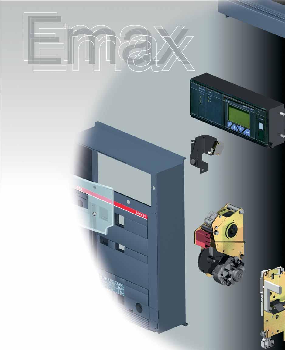
79

80 Accessories Contents Functions of the accessories... 4/2 Accessories supplied as standard... 4/3 Accessories supplied on request... 4/4 Shunt trip and closing coils... 4/6 Undervoltage release... 4/8 Gearmotor for the automatic charging of closing springs... 4/10 Bell alarm... 4/11 4 Auxiliary contacts... 4/12 Current sensors and operation counters... 4/15 Mechanical safety locks... 4/16 Transparent protective covers... 5/18 Mechanical interlock... 4/19 Controller for Automatic Transfer Switch - ATS010 (IEC only)... 4/22 Spare parts... 4/25 ABB 4/1
81 Functions of the accessories The following table lists a few functions that can be obtained by selecting the appropriate accessories. Several of the functions listed can be needed at the same time depending on how the circuit breaker is used. See the related section for a detailed description of the individual accessories. Function Components Electrical operated Shunt trip Closing coil Gearmotor for the automatic charging of closing springs Remote signaling or actuation of automatic functions depending on the state (open-closed) or position (racked-in, test isolated, racked-out) of the circuit breaker. Auxiliary contacts of open-closed circuit breaker Auxiliary contacts of circuit breaker racked-in, test isolated, racked-out (draw out circuit breaker only) Bell alarm Contact for signaling undervoltage release de-energized Contact for signaling springs charged 4 Remote opening for various needs, including: manual emergency control opening dependent on tripping of other interruption devices or system automation needs (1). Opening or undervoltage release Automatic opening of the circuit breaker for undervoltage (for example, when operating asynchronous motors) Instantaneous or time delay undervoltage release (IEC only) (2) Contact for signaling undervoltage release energized Increased degree of protection IP54 door protection Mechanical safety locks for maintenance or functional requirements for interlocking two or more circuit breakers Kirk key provision Key lock in open position Padlock device in open position Key lock and padlocks in racked-in, test isolated, racked-out position Automatic switching of power supplies Mechanical interlock between two or three circuit breakers Automatic transfer switch - ATS010 (IEC only) (1) Examples: circuit breakers on Low Voltage side of parallel transformers that must open automatically when the Medium Voltage side device opens. automatic opening for control by external relay (undervoltage, residual current, etc.). 4/2 (2) The time-delay device is recommended when unwanted operation due to temporary voltage drops, is to be avoided (for functional or safety reasons). ABB
82 Accessories supplied as standard The following standard accessories are supplied depending on the circuit breaker version: Note: (*) not supplied with the switch version Fixed circuit breaker: flange for switchboard compartment door support for service releases four auxiliary contacts for electrical signaling of circuit breaker open/closed (they are not supplied with the switch version) mechanical indication of trip (*) terminal box for connecting outgoing auxiliaries horizontal rear terminals lifting plate 4 Note: (*) not supplied with the switch version Draw out circuit breaker: flange for switchboard compartment door support for service releases four auxiliary contacts for electrical signaling of circuit breaker open/closed mechanical indication of trip (*) sliding contacts for connecting outgoing auxiliaries horizontal rear terminals anti-insertion lock for circuit breakers with different continuous current ratings racking-out crank handle lifting plate anti-racking-out device when springs are charged (fail safe) ABB 4/3
83 Accessories supplied on request All the accessories Circuit breaker 1a) Shunt trip/closing coil (YO/YC) and second shunt trip (YO2) 1b) SOR test unit (IEC only) 2a) Undervoltage release (YU) 2b) Time-delay device for undervoltage release (D) (IEC only) 3) Gearmotor for the automatic charging of the closing springs (M) 4a) Bell alarm 4b) Bell alarm with remote reset command 5a) Electrical signaling of circuit breaker open/closed (1) 5b) External supplementary electrical signaling of circuit breaker open/closed 5c) Electrical signaling of circuit breaker racked-in/test isolated/racked-out 5d) Contact signaling closing springs charged 5e) Contact signaling undervoltage release de-energized (C. Aux YU) 6a) External current sensors for neutral conductor outside circuit breaker 6b) Homopolar toroid for the main power supply grounding conductor (star center of the transformer) 4 7) Mechanical operation counter 8a) Lock in open position: key 8b) Lock in open position: padlocks 8c) Circuit breaker lock in racked-in/test isolated/racked-out position 8d) Accessories for lock in test isolated/racked-out position 8e) Padlock device for safety shutter 8f) Mechanical lock for compartment door 8g) Anti-racking-out device when the springs are charged (FAIL SAFE) 9a) Protection for opening and closing pushbuttons 9b) IP54 door protection 10) Mechanical interlock 11) Controller for Automatic Transfer Switch - ATS010 (IEC only) CAPTION n n n Accessory on request on fixed circuit breaker or moving part Accessory on request on cradle Accessory on request on moving part 4/4 ABB
84 Circuit breakers Switches (MS) Fixed Draw out Fixed Draw out n n n n n n n n n n n n n n n n n n n n n n n n n n n n n n n n n n n n n n n n n n n n n n n n n n n n n n n n n n n n n n n n n n n n n n n n n n n n n n n n n n n n n n 4 (1) For automatic circuit breakers, four auxiliary contacts are included as standard. ABB 4/5
85 Shunt trip and closing coils (1) The minimum impulse current must be 100 ms (2) If the shunt trip is permanently connected to the power supply, wait at least 30 ms before sending the command to the closing coil. 1a) Shunt trip/closing coil (YO/YC) and second shunt trip (YO2) They allow the remote control of the circuit breaker. The accessory is the same and the function depends on the installation position on the circuit breaker. It can be used for either of these applications. Given the characteristics of the circuit breaker operating mechanism, opening (with the circuit breaker closed) is always possible, while closing is only possible when the closing springs are charged. The release can operate with either direct current or alternating current. This release can be operated by a pulse (1), or with a permanent signal (2). For safety reasons, Emax can be equipped with a second shunt trip, mounted on a special support in alternative to the UVR. If the closing coil is powered with a continuous signal, the presence of the anti-pumping device requires after an opening operation to momentarily de-energize the closing coil. Reference figure in circuit diagrams: YO (4) - YC (2) - YO2 (8) 1SDC200102F SDC200103F0003 1SDC200104F0003 1SDC200105F0003 Characteristics Power supply (Un): 24 V DC V AC/DC 30 V AC/DC V AC/DC 48 V AC/DC 250 V AC/DC 60 V AC/DC V AC V AC/DC V AC Operating limits: (YO-YO2): 70% % Un (YC): 85% % Un Inrush power (Ps): DC = 200 W Inrush time ~100 ms AC = 200 VA Continuous power (Pc): DC = 5 W AC = 5 VA Opening time (YO- YO2): (max) 60 ms Closing time (YC) (max) 80 ms Insulation voltage: 2500 V 50 Hz (for 1 min) 4/6 ABB

86 1SDC200106F0003 1b) SOR Test Unit (IEC only) Under particularly severe operating conditions or simply for remote control of the circuit breaker, the shunt trip is widely used as an accessory for the Emax series of power circuit breakers. The right working of all functions of this accessory is a necessary condition to guarantee a high level of safety in the installation: this means there is the need to have a device available which cyclically checks correct operation of the release, signaling any malfunctions. The SOR control and monitoring Test Unit ensures continuity of shunt trips with a rated operating voltage between 24 V and 250 V (AC and DC), as well as the functions of the opening coil electronic circuit. Continuity is checked cyclically with an interval of 20s between tests. The unit has LEDs on the front, which provide the following information: POWER ON: power supply present YO TESTING: test in progress TEST FAILED: signal following a failed test or lack of auxiliary power supply ALARM: signal following three failed tests. Two relays with one change-over are also available, which allow remote signaling of the following two events: failure of a test (resetting takes place automatically when the alarm stops ) failure of three tests (resetting only occurs by pressing the manual RESET on the front of the unit) 4 Characteristics Auxiliary power Maximum interrupted current Maximum interrupted voltage 24 V V AC/DC 6 A 250V AC ABB 4/7
87 Undervoltage release 1SDC200107F0003 2a) Undervoltage release (YU) The undervoltage release opens the circuit breaker when there is a significant voltage drop in the power supply. It can be used also to open the circuit breaker (using normally closed pushbuttons), as a lock in closing position. The power supply is therefore obtained on the supply side of the circuit breaker or from an independent source. The circuit breaker can be closed only when the release is energized. The release can operate with either direct current or alternating current. When the voltage drops down below the 10% of the rated voltage, the UVR trips the breaker. The circuit breaker can be closed with voltage higher than of 85%. It can be fitted with a contact to signal when the undervoltage release is energized (C. aux YU; see accessory 5e). Note With the undervoltage release, the use of the anti-racking-out device is not allowed. Reference figure in circuit diagrams: YU (6) 4 Characteristics Power supply (Un): 24 V DC V AC/DC 30 V AC/DC V AC/DC 48 V AC/DC 250 V AC 60 V AC/DC V AC V AC/DC V AC Inrush power (Ps): DC = 200 W AC = 200 VA Continuous power (Pc): DC = 5 W AC = 5 VA Opening time (YU) 30 ms Insulation voltage: 2500 V 50 Hz (for 1 min) 1SDC200108F0003 4/8 ABB

88 1SDC200109F0003 2b) Time-delay device for undervoltage release (D) (IEC only) The undervoltage release can be combined with an electronic time-delay device mounted outside the circuit breaker. Use of the delayed undervoltage release is recommended to prevent tripping when the power supply network can be subject to brief voltage drops. The time-delay device must be used with an undervoltage release with the same operating voltage. Reference figure in circuit diagrams: YU +D (7) Characteristics Power supply (D): Adjustable opening time (YU+D): V DC 48 V AC/DC 60 V AC/DC V AC/DC V AC/DC s 4 ABB 4/9

89 Gearmotor for the automatic charging of closing springs 1SDC200110F0003 3) Gearmotor for the automatic charging of closing springs (M) This accessory automatically charges the closing springs of the circuit breaker operating mechanism. The gearmotor immediately recharges the closing springs after closing the circuit breaker. The closing springs can, however, be charged manually (using the relative operating lever) in the event of a power supply failure or during maintenance. It is always supplied with a limit switch for signaling that the closing springs are charged (see accessory 5d). Reference figure in circuit diagrams: M (1) 4 Characteristics Power supply Operating limits: Inrush power (Ps): Rated power (Pn): Inrush time Charging time: Insulation voltage: V AC/DC V AC/DC V AC/DC V AC/DC 85%...110% Un DC = 500 W AC = 500 VA DC = 200 W AC = 200 VA 0.2 s 4-5 s 2500 V 50 Hz (for 1 min) 1SDC200111F0003 4/10 ABB
90 Bell alarm 4) Bell alarm The following signals are available after the trip unit tripped. 4a) Bell alarm Allows the local (mechanical accessory supplied as standard) and remote signaling (electrical by means of changeover switch) that the circuit breaker is open following operation of the trip units. The mechanical signaling pushbutton must be rearmed to reclose the circuit breaker. Reference figure in circuit diagrams: S51 (13) 4 1SDC200144F0001 1SDC200141F0001 4b) Bell alarm with remote reset command Allows the local (mechanical accessory supplied as standard) and remote signaling (electrical by means of changeover switch) that the circuit breaker is open following operation of the trip units. With this accessory, it is possible to reset the mechanical signaling pushbutton via an electrical coil from remote command, with allows the circuit breaker to be reset. Available reset coils V AC/DC V AC/DC V AC/DC Reference figure in circuit diagrams: S51 (14) ABB 4/11

91 Auxiliary Contacts 5) Auxiliary contacts Auxiliary contacts are available installed on the circuit breaker, which enable signaling of the circuit breaker status. Characteristics Un In max T 125 V DC 0.3 A 10 ms 250 V DC 0.15 A Un In max cosj 250 V AC 15 A 0.3 The versions available are as follows: 4 1SDC200116F0003 5a-5b) Electrical signaling of circuit breaker open/closed It is possible to have electrical signaling of the status (open/ closed) of the circuit breaker using 4, 10 or 15 auxiliary contacts. The auxiliary contacts have the following configurations: 4 open/closed contacts for PR121 (2 normally open + 2 normally closed) 4 open/closed contacts for PR122/PR123 (2 normally open + 2 normally closed + 2 dedicated to trip unit) 10 open/closed contacts for PR121 (5 normally open + 5 normally closed) 10 open/closed contacts for PR122/PR123 (5 normally open + 5 normally closed + 2 dedicated to trip unit) 15 supplementary open/closed contacts for installation outside the circuit breaker. The standard configuration NO/NC described above can be modified by the user by repositioning the faston connector on the microswitch. When 10 open/closed contacts for PR122/PR123 are required, the zone discrimination and PR120/K unit are not available. Reference figures in circuit diagrams: Q/1 10 (21-22) 1SDC200117F0003 4/12 ABB
92 5c) Electrical signaling of circuit breaker racked-in/test isolated/racked-out 1SDC200118F0003 In addition to mechanical signaling of the circuit breaker position, it is also possible to have a remote signal using 5 or 10 auxiliary contacts which are installed into the cradle. The auxiliary contacts take on the following configurations: 5 contacts: 2 contacts for racked-in signal, 2 contacts for racked-out signal, and 1 contact to signal the test isolated position (main power isolated, but sliding contacts connected). 10 contacts: 4 contacts for racked-in signal, 4 contacts for racked-out signal, and 2 contacts to signal the test isolated position (main power isolated, but sliding contacts connected). Reference figures in circuit diagrams: S75I (31-32) S75T (31-32) S75E (31-32) 4 1SDC200119F0003 ABB 4/13
 1SDC200120F0003 4 1SDC200121F0003 5e) Contact signaling undervoltage release de-energized (C.")
93 Auxiliary Contacts 5d) Contact signaling closing springs charged A microswitch allows remote signaling of the status of the closing springs (always supplied with the spring charging geared motor). Reference figure in circuit diagrams: S33 M/2 (11) 1SDC200120F SDC200121F0003 5e) Contact signaling undervoltage release de-energized (C. Aux YU) The undervoltage releases can be fitted with a contact for signaling remotely the status of the undervoltage release. Reference figure in circuit diagrams: (12) 1SDC200123F0003 1SDC200122F0003 4/14 ABB

 to")
, the In of the same toroid can be set at 100 A, 250 A, 400 A, 800 A.")
94 Current sensors and operation counters 6a) External current sensors for neutral conductor outside circuit breaker For three-pole circuit breakers only, this allows protection of the neutral by connection to the trip unit. Reference figure in circuit diagrams: UI/N (see page 6/8) 1SDC200124F0003 1SDC200125F0003 6b) Homopolar toroid for the main power supply grounding conductor (star center of the transformer) PR122 and PR123 electronic trip units can be used in combination with an external toroid located on the conductor, which connects the star center of the MV/LV transformer (homopolar transformer) to ground. In this case, the ground protection is defined as Source Ground Return. Through to different combinations of its terminals (see chapter 6), the In of the same toroid can be set at 100 A, 250 A, 400 A, 800 A. Reference figure in circuit diagrams: UI/O (see page 6/8) 4 7) Mechanical operation counter This is connected to the operating mechanism by means of a simple lever mechanism, and indicates the number of mechanical operations carried out by the circuit breaker. The count is shown on the front of the circuit breaker. 1SDC200127F0003 1SDC200126F0003 ABB 4/15
: a special circular lock with different keys (for a single circuit breaker) or the same keys (for several circuit breakers).")
95 Mechanical locks 1SDC200128F0003 8) Mechanical locks 8a-8b) Lock in open position Several different mechanisms are available which allow the circuit breaker to be locked in the open position. These devices can be controlled by: Key (8a): a special circular lock with different keys (for a single circuit breaker) or the same keys (for several circuit breakers). Padlocks (8b): up to 3 padlocks (not supplied): ø 4 mm. Provision for Kirk key 1SDC200129F0003 1SDC200130F SDC200131F0003 8c) Circuit breaker lock in racked-in/test isolated/rackedout position It is available a key lock (with same of different keys) or a padlock device (up to 3 padlock with a max ø of 4 mm). It is only available for draw out circuit breakers, to be installed on the moving part. 1SDC200132F0003 8d) Accessories for lock in test isolated/racked-out position 1SDC200133F0003 In addition to the circuit breaker lock in racked-in/test isolated/ racked-out position, this allows the circuit breaker to be locked only in the racked-out or test isolated positions. It is only available for draw out circuit breakers, to be installed on the moving part. 4/16 ABB
 Mechanical lock for compartment door Locks the compartment door from being opened when the circuit breaker is closed (and circuit breaker racked-in for draw out")
96 8e) Padlock device for safety shutter Allows the shutters into the cradle to be padlocked in the closed position. 1SDC200135F0003 1SDC200134F f) Mechanical lock for compartment door Locks the compartment door from being opened when the circuit breaker is closed (and circuit breaker racked-in for draw out circuit breakers) and prevents the circuit breaker from closing when the compartment door is open. 1SDC200136F0003 8g) Anti-racking-out device when the springs are charged (FAIL SAFE) Note This accessory, always supplied with the draw out version circuit breaker, is an alternative to the undervoltage release. Prevents the moving part of the draw out version circuit breaker from being racked out of the cradle when the springs are charged. ABB 4/17

97 Transparent protective covers 1SDC200137F0003 9) Transparent protective covers 9a) Protection for opening and closing pushbuttons These protections are fitted on the opening and closing pushbuttons, preventing the relative circuit breaker operations unless a special tool is used. 1SDC200138F b) IP54 door protection (NEMA 3/S/13) This is a transparent plastic protective cover which completely protects the front panel of the circuit breaker. Mounted on hinges, it is fitted with a key lock. 1SDC200140F0003 1SDC200139F0003 4/18 ABB
 using flexible cables. The electrical diagram for electrical switching by means of a relay (to be provided by the customer) is supplied with the mechanical interlock.")
98 Interlock between circuit breakers 1SDC200141F ) Mechanical interlock This mechanism creates a mechanical interlock between two or three circuit breakers (even different models and in any fixed/ draw out version) using flexible cables. The electrical diagram for electrical switching by means of a relay (to be provided by the customer) is supplied with the mechanical interlock. The circuit breakers can be installed vertically or horizontally. Four types of mechanical interlocks are available: Type A: between 2 circuit breakers (power supply + emergency power supply) Type B: between 3 circuit breakers (2 power supplies + emergency power supply) Type C: between 3 circuit breakers (2 power supplies + bus-tie) Type D: between 3 circuit breakers (3 power supplies/one single closed circuit breaker) Note See the chapters Overall dimensions and Circuit diagrams for information about dimensions (fixed and draw out versions) and settings. 4 1SDC200142F0003 1SDC200143F0003 Vertical interlock Horizontal interlock ABB 4/19
99 Interlock between circuit breakers The possible mechanical interlocks are shown below, depending on whether 2 or 3 circuit breakers (any model in any version) are used in the switching system. Type of interlock Typical circuit Possible interlocks Type A Between two circuit breakers One normal power supply and one emergency power supply G Circuit breaker 1 can only be closed if 2 is open, and vice-versa. 1 2 O O 1 2 I O O I O = Circuit breaker open I = Circuit breaker closed Type B 4 Between three circuit breakers Two normal power supplies and one emergency power supply. G O = Circuit breaker open Circuit breakers 1 and 3 can only be closed if 2 is open. Circuit breaker 2 can only be closed if 1 and 3 are open O O O I O O O O I I O I O I O I = Circuit breaker closed Type C Between three circuit breakers The two half-busbars can be supplied by a single transformer (bus-tie closed) or by both at the same time (bus-tie open) One or two circuit breakers out of three can be closed at the same time O O O I O O O I O O O I O = Circuit breaker open I = Circuit breaker closed O I I I I O I O I Type D Between three circuit breakers Three power supplies (generators or transformers) on the same busbar, so parallel operation is not allowed G Only one of three circuit breakers can be closed O O O I O O O I O O O I O = Circuit breaker open I = Circuit breaker closed 4/20 ABB
100 The emergency power supply is usually installed to take over from the normal power supply in two instances: to supply safety services for people (e.g., hospital installations); to supply parts of installations which are essential for requirements other than safety (e.g., continuous-cycle industrial plants). The range of accessories for Emax circuit breakers includes solutions for a wide variety of different plant engineering requirements. See the specific regulations regarding protections against overcurrents, direct and indirect contacts, and provisions to improve the reiliability and safety of emergency circuits. Switching from the normal to the emergency power supply can be carried out manually (locally or by remote control) or automatically. To this end, the circuit breakers used for switching must be fitted with the accessories required to allow electric remote control and to provide the electrical and mechanical interlocks required by the switching logic. These include: the shunt trip the closing coil the motor control the auxiliary contacts. Switching can be automated by means of special electroniccontroll, to be installed by the customer (diagrams provided by ABB). 4 ABB 4/21

101 Controller for Automatic Transfer Switch - ATS010 (IEC only) 1SDC200148F ) Controller for Automatic Transfer Switch - ATS010 (IEC only) The ATS010 controller is the new network-unit switching device offered by ABB. It is based on microprocessor technology in compliance with the major electromagnetic compatibility and environmental standards (EN 50178, EN , EN , IEC , IEC , IEC ). The device is able to manage the entire switching procedure between the normal line and emergency line circuit breakers automatically, allowing great flexibility of settings. In case of fault in the normal line voltage, in accordance with the delays set, the normal line circuit breaker is opened, the generator started and the emergency line circuit breaker closed. Similarly, when the normal line returns to range, the reverse switching procedure is automatically controlled. It is especially suited for use in all emergency power supply systems requiring a solution that is ready to install, easy to use and reliable. Some of the main applications include: power supply for UPS (Uninterrupted Power Supply) units, operating theatres and primary hospital services, emergency power supply for civilian buildings, airports, hotels, data banks and telecommunication systems, and power supply of industrial lines for continuous processes. 4 The switching system consists of the ATS010 unit connected to two motor-driven and mechanically interlocked circuit breakers. Any of the circuit breakers in the Emax series can be used. The built-in main sensor of the ATS010 device makes it possible to detect faults in the main voltage. The three inputs can be directly connected to the three phases of the normal power supply line for networks with rated voltage up to 500V AC. Networks with a higher voltage require the insertion of potential transformers (PT), setting a rated voltage for the device that matches their secondary voltage (typically 100V). Two change-over contacts for each circuit breaker allow direct connection to the shunt trip and closing coils. The circuit breaker connection is completed by wiring the status contacts: Open/ Closed, Relay tripped, Racked-in (for draw out/plug-in circuit breakers). For this reason, apart from the mechanical interlock accessories, the following are provided on each circuit breaker connected to the ATS010 unit: spring charging motor, opening and closing coil, open/closed contact, racked-in contact (for draw out versions), signal and mechanical lock for protection relay tripped. The ATS010 device is designed to ensure extremely high reliability for the system it controls. It contains various safety systems intrinsically related to software and hardware operation. For software safety, a special logic prevents undesired operations, while a constantly operative watchdog system points out any microprocessor malfunctions by means of a LED on the front of the device. Hardware safety allows integration of an electrical interlock by means of a power relay, making the use of an external electrical interlocking system superfluous. The manual selector on the front of the device can also control the entire switching procedure, even in the event of a microprocessor fault, by working electromechanically on the control relays. 4/22 ABB
102 General specifications Rated supply voltage 24V DC ± 20% 48V DC ± 10% (galvanically insulated from ground) (maximum ripple ± 5%) Maximum absorbed power 5W at 24V DC 10W at 48V DC Rated power (mains present and circuit breakers not controlled) 1.8W at 24V DC 4.5W at 48V DC Operating temperature -25 C +70 C Maximum humidity 90% without condensation Storage temperature -25 C +80 C Degree of protection IP54 (front panel) Dimensions [mm] 144 x 144 x 85 Weight [kg] 0.8 Setting range for thresholds and times Minimum voltage Un Min -5% -30% Un Maximum voltage Un Max +5% +30% Un Fixed frequency thresholds 10% +10% fn t1: opening delay of the normal line circuit breaker due to network error (CB-N) 0 32 s t2: generator start-up delay due to network error 0 32 s t3: stopping delay of the generator s t4: switching delay due to network stop s t5: closing delay of the emergency line circuit breaker after detecting the generator voltage (CB-E) 0 32 s 4 Rated voltage settings available 100, 115, 120, 208, 220, 230, 240, 277, 347, 380, 400, 415, 440, 480, 500 V Operating sequence VN CB-N t1 GE VE t2 t3 Caption VN Main voltage CB-N Normal line circuit breaker closed GE Generator VE Emergency line voltage CoCo Enable switching to emergency line CB-E Emergency line circuit breaker closed LOAD Disconnection of lower priority connected loads CoCo CB-E LOAD t5 t4 ABB 4/23
103 Controller for Automatic Transfer Switch - ATS010 (IEC only) Front panel SDC200149F Caption 1 Status of the ATS010 unit and logic 2 Operating mode selector 3 Normal line check 4 Normal line circuit breaker status 5 Voltage on the emergency line 6 Emergency line circuit breaker status 7 Generator status 4 Side panel settings SDC200150F0003 Caption 1 Selectors to set the under- and overvoltage thresholds 2 Dip-switches to set: rated voltage normal single-phase or three-phase line mains frequency switching strategy 3 Switching delay time settings for t1... t5 4/24 ABB
104 Spare parts Spare parts The following spare parts are available: front shields and escutcheon plate opening solenoid for PR121, PR122 and PR123 trip units arcing chamber closing springs plier isolation contact for the cradle of the draw out circuit breaker grounding sliding contact (for draw out version) shutters for cradle complete pole operating mechanism connection cables between releases and current transformers transparent protective cover for releases PR130/B power supply unit toolbox battery for PR130/B power supply unit front escutcheon plate for Ronis key lock For further details, request a copy of the ABB spare parts catalog. 4 ABB 4/25

105

106 Overall dimensions Contents Fixed circuit breaker... 5/2 Draw out circuit breaker... 5/7 Installation in switchboard... 5/15 Mechanical interlock... 5/16 Circuit breaker accessories... 5/18 5 ABB 5/1
107 Overall dimensions Fixed circuit breaker Basic version with horizontal rear terminals [mm/in] E1 5 E2-E3 E4-E6 1SDC200065F0201 Caption A 3 Poles B 4 Poles 1 Insulating wall or insulated metal wall E1-A E2-A 296/11.65'' 296/11.65'' 386/15.2'' 386/15.2'' E3-A 404/15.91'' 530/20.87'' E4-A 566/22.28'' 656/25.83'' E6-A 782/30.79'' 908/35.75'' 5/2 ABB
108 [mm/in] E1 3 poles / E2 3 poles E1 4 poles / E2 4 poles E3 3 poles E3 4 poles 5 Caption 1SDC200066F Inside edge of compartment door 2 Segregation (when provided) 3 M10 mounting holes for circuit breaker (included in the supply) 41x M12 screw for earthing (included in the supply) ABB 5/3
109 Overall dimensions Fixed circuit breaker Basic version with horizontal rear terminals [mm/in] E4 3 poles E4 4 poles E6 3 poles E6 4 poles 5 1SDC200067F0201 Caption 1 Inside edge of compartment door 2 Segregation (when provided) 3 M10 mounting holes for circuit breaker (included in the supply) 41x M12 screw for earthing (included in the supply) 5/4 ABB
110 Basic version with vertical rear terminals [mm/in] E1 E2 E A E1 E2 E A 5 1SDC200068F0201 ABB 5/5
111 Overall dimensions Fixed circuit breaker Basic version with vertical rear terminals [mm/in] E A E4 E6 E A E4 E6 5 1SDC200069F0201 5/6 ABB
112 Overall dimensions Draw out circuit breaker Basic version with horizontal rear terminals [mm/in] E1 E2-E3-E4-E6 5 A 3 Poles B 4 Poles E1-A 324/12.76'' 414/16.3'' E2-A 324/12.76'' 414/16.3'' 1SDC200070F0201 E3-A E4-A E6-A 432/17.01'' 594/23.39'' 810/31.89'' 558/21.97'' 684/26.93'' 936/36.85'' Caption 1 Distance from connected for testing to isolated ABB 5/7
113 Overall dimensions Draw out circuit breaker Basic version with horizontal rear terminals [mm/in] E1 3 poles / E2 3 poles E1 4 poles / E2 4 poles E3 3 poles E3 4 poles 5 1SDC200071F0201 Caption 1 Inside edge of compartment door 2 Segregation (when provided) 3 M8 mounting holes for circuit breaker (included in the supply) 41x M12 screws for earthing (included in the supply) 5 4 holes for mounting fixed part (standard) 5/8 ABB
114 [mm/in] E4 3 poles E4 4 poles E6 3 poles E6 4 poles 5 1SDC200072F0201 Caption 1 Inside edge of compartment door 2 Segregation (when provided) 3 M8 mounting holes for circuit breaker (included in the supply) 41x M12 screw for earthing (included in the supply) ABB 5/9
115 Overall dimensions Draw out circuit breaker Basic version with vertical rear terminals [mm/in] E1 3 poles / E2 3 poles E1 4 poles / E2 4 poles 5 E1-E2 Caption 1 Inside edge of compartment door 2 Segregation (when provided) 1SDC200073F M8 mounting holes for circuit breaker (included in the supply) 5 Distance from connected for testing to isolated 5/10 ABB
116 [mm/in] E3 3 poles A E3 4 poles A E A 5 Caption 1 Inside edge of compartment door 2 Segregation (when provided) 3 M8 mounting holes for circuit breaker (included in the supply) 1SDC200074F x M12 screws for earthing (included in the supply) 5 Distance from connected for testing to isolated ABB 5/11
117 Overall dimensions Draw out circuit breaker Basic version with vertical rear terminals [mm/in] E3 3 poles 2500 A (*) E3 4 poles 2500 A (*) 5 E A (*) Caption 1SDC200075F Inside edge of compartment door 2 Segregation (when provided) 3 M8 mounting holes for circuit breaker (included in the supply) 42x M12 screws for earthing (included in the supply) (*) Ask ABB for E A dimensions. 5 Distance from connected for testing to isolated 5/12 ABB
118 [mm/in] E4 3 poles E4 4 poles E4 5 Caption 1SDC200076F Inside edge of compartment door 2 Segregation (when provided) 3 M8 mounting holes for circuit breaker (included in the supply) 42x M12 screws for earthing (included in the supply) 5 Distance from connected for testing to isolated ABB 5/13
119 Overall dimensions Draw out circuit breaker Basic version with vertical rear terminals [mm/in] E6 3 poles E6 4 poles 5 E6 Caption 1 Inside edge of compartment door 2 Segregation (when provided) 3 M8 mounting holes for circuit breaker (included in the supply) 1SDC200077F x M12 screws for earthing (included in the supply) 5 Distance from connected for testing to isolated 5/14 ABB
120 Overall dimensions Installation in switchboard [mm/in] Dimensions of compartment Copper bars Insulating support 1SDC200078F0201 A 3 Poles A 4 Poles E1-A E2-A E3-A (*) E4-A (*) E6-A (*) 400/11.65'' 490/19.30'' 400/15.7'' 490/19.30'' 500/19.7'' 630/24.82'' 700/25.7'' 790/30.62'' 1000/39.3'' 1130/44.52'' (*) Ask ABB for V-A and L-A versions. ** Suitable for continuous operation at 100% rating in a minimum cubicle space (see the table), with a ventilation of 48 (12x4) sq. in. side bottom and side top. Refer to shop drawings for verification. 5 Drilling of compartment door Tightening torque for fastening screws Nm lb/in Tightening torque for main terminals Nm lb/in Tightening torque for earthing screw Nm lb/in High strength M12 screw Number per terminal PHASE NEUTRAL N E1-E2 2 2 N E3 3 3 N E SDC200079F0201 N E SDC200080F0201 ABB 5/15
121 Overall dimensions Mechanical interlock Interlock assembly [mm/in] Type A Horizontal Vertical Type B (emergency interlock below) Horizontal Vertical Type B (emergency interlock in the middle) Horizontal Vertical Type B (emergency interlock above) Horizontal Vertical Type C Horizontal Vertical 5 Type D Horizontal Vertical 1SDC200081F0201 Horizontal interlocks Maximum distance between two interlocks: 1200/ mm from one interlock to the other. The cables pass under the cradles, following the same connection diagram shown for vertical circuit breakers. Notes When fitting interlocks between two circuit breakers, it is necessary to make suitable holes (through the switchboard) in the mounting surface for fixed circuit breakers or for the cradle of draw out circuit breakers, in order to pass the flexible cables through, respecting the measurements shown in the figures on page 5/17. For vertical interlocks, align the right-hand sides vertically and reduce the bends in the flexible cables to a minimum (minimum radius R. 70 mm / 2.76 in). All the angle values of the bends which the cable passes through added together must not exceed SDC200082F0201 Take up the excess cable by making it go through only one complete turn or an omega as shown in the figure. 5/16 ABB
122 Through-holes for flexible cables for mechanical interlocks 1SDC200083F ABB 5/17
123 Overall dimensions Circuit breaker accessories Mechanical compartment door lock [mm/in] Drilling in compartment door Minimum distance between circuit breaker and switchboard wall Fixed version Draw out version A 3 Poles 4 Poles 1SDC200084F0201 E E E E E Homopolar toroid (IEC only) 1SDC200085F0201 5/18 ABB
124 Current sensor for the external neutral [mm/in] E1 - E2 - E4 E3 - E6 5 1SDC200086F0201 ABB 5/19
125 Overall dimensions Circuit breaker accessories Electrical signaling of circuit breaker open/closed [mm/in] 15 supplementary auxiliary contacts 1SDC200087F A flexible cable 650 mm / in long is available from point A to point B. Fixed version Draw out version 1SDC200088F0201 5/20 ABB
126 ATS010 (IEC only) [mm/in] 1SDC200089F0201 Electronic time-delay device (IEC only) 5 1SDC200090F0201 ABB 5/21
 1SDC200092F0201 5/22")
127 Overall dimensions Circuit breaker accessories IP54 Protective cover [mm/in] 1SDC200091F PR021/K Unit (IEC only) 1SDC200092F0201 5/22 ABB
128 ABB 5/23 5

129
... 6/7 Circuit diagrams Circuit breakers... 6/8 Electrical accessories... 6/9 Automatic transfer switch - ATS010 (IEC only)... 6/14 6 ABB 6/1")
130 Circuit diagrams Contents Reading information - circuit breakers... 6/2 Reading information - ATS010 unit... 6/6 Circuit diagram symbols (IEC and CEI Standards)... 6/7 Circuit diagrams Circuit breakers... 6/8 Electrical accessories... 6/9 Automatic transfer switch - ATS010 (IEC only)... 6/14 6 ABB 6/1
131 Circuit diagrams Reading information - circuit breakers Warning Before installing the circuit breaker, carefully read notes F and O on the circuit diagrams. Operating status shown The circuit diagram is shown under the following conditions: - draw out circuit breaker, open and racked-in - circuits de-energized - trip units not tripped - motor operator with springs discharged. Versions Though the diagram shows a circuit breaker in draw out version, it can be applied to a fixed version circuit breaker as well. Fixed version The control circuits are fitted between terminals XV (connector X is not supplied). With this version, the applications indicated in figures 31 and 32 cannot be provided. Draw out version The control circuits are fitted between the poles of connector X (terminal box XV is not supplied). Version without overcurrent trip unit With this version, the applications indicated in figures 13, 14, 41, 42, 43, 44, 45, 46, 47 cannot be provided. Version with PR121/P electronic trip unit With this version, the applications indicated in figures 42, 43, 44, 45, 46, 47 cannot be provided. Version with PR122/P electronic trip unit With this version, the applications indicated in figure 41 cannot be provided. Version with PR123/P electronic trip unit With this version, the applications indicated in figure 41 cannot be provided. 6 Caption = Circuit diagram figure number * = See note indicated by letter A1 = Circuit breaker accessories A3 = Accessories applied to the cradle of the circuit breaker (for draw out version only) A4 = Example switchgear and connections for control and signaling, outside the circuit breaker AY = SOR TEST UNIT control/monitoring Unit (see note R) D = Electronic time-delay device of the undervoltage release, outside the circuit breaker F1 = Delayed-trip fuse K51 = PR121/P, PR122/P, PR123/P electronic trip unit with the following protection functions (see note G): - L overload protection with inverse long time-delay trip - setting I1 - S short-circuit protection with inverse or definite short time-delay trip - setting I2 - I short-circuit protection with instantaneous time-delay trip - setting I3 - G ground fault protection with inverse short time-delay trip - setting I4 K51/1 8 = Contacts of the PR021/K signaling unit. K51/GZin = Zone discrimination: input for protection G or reverse direction input for protection D (only with (DBin) Uaux. and PR122/P or PR123/P trip unit) K51/GZout = Zone discrimination: output for protection G or reverse direction output for protection D (only with (DBout) Uaux. and PR122/P or PR123/P trip unit) K51/IN1 = Digital programmable input (available only with Uaux and PR122/P or PR123/P trip unit with indicator module PR120/K) K51/P1 P4 = Programmable electrical signaling (available only with Uaux and PR122/P or PR123/P trip unit with indicator module PR120/K) K51/SZin = Zone discrimination: input for protection S or direct input for protection D (only with Uaux. and PR122/P (DFin) or PR123/P trip unit) K51/SZout = Zone discrimination: output for protection S or direct output for protection D (only with Uaux. and (DFout) PR122/P or PR123/P trip unit) K51/YC = Closing control from PR122/P or PR123/P electronic trip unit with communication module PR120/D-M K51/YO = Opening control from PR122/P or PR123/P electronic trip unit with communication module PR120/D-M 6/2 ABB
132 M Q Q/ S33M/1 S43 S51 S75E/1...4 S75I/1...4 S75T/1..4 SC SO SO1 SO2 SR TI/L1 TI/L2 TI/L3 = Motor for charging the closing springs = Circuit breaker = Circuit breaker auxiliary contacts = Limit contacts for spring-charging motor = Switch for setting remote/local control = Contact for electrical signaling of circuit breaker open due to tripping of the overcurrent trip unit. The circuit breaker may be closed only after pressing the reset pushbutton, or after energizing the coil for electrical reset (if available). = Contacts for electrical signaling of circuit breaker in racked-out position (only with draw out circuit breakers) = Contacts for electrical signaling of circuit breaker in racked-in position (only with draw out circuit breakers) = Contacts for electrical signaling of circuit breaker in test isolated position (only with draw out circuit breakers) = Pushbutton or contact for closing the circuit breaker = Pushbutton or contact for opening the circuit breaker = Pushbutton or contact for opening the circuit breaker with delayed trip = Pushbutton or contact for opening the circuit breaker with instantaneous trip = Pushbutton or contact for electrical circuit breaker reset = Current transformer located on phase L1 = Current transformer located on phase L2 = Current transformer located on phase L3 Uaux. = Auxiliary power supply voltage (see note F) UI/L1 = Current sensor (Rogowski coil) located on phase L1 UI/L2 = Current sensor (Rogowski coil) located on phase L2 UI/L3 = Current sensor (Rogowski coil) located on phase L3 UI/N = Current sensor (Rogowski coil) located on neutral UI/O = Current sensor (Rogowski coil) located on the conductor connecting to ground the star point of the MV/LV transformer (see note G) W1 = Serial interface with control system (external bus): EIA RS485 interface (see note E) W2 = Serial interface with the accessories of PR121/P, PR122/P and PR123/P trip units (internal bus) X = Delivery connector for auxiliary circuits of draw out version circuit breaker X1...X7 = Connectors for the accessories of the circuit breaker XF = Delivery terminal box for the position contacts of the draw out circuit breaker (located on the cradle of the circuit breaker) XK1 = Connector for power circuits of PR121/P, PR122/P, and PR123/P trip units. XK2 - XK3 = Connectors for auxiliary circuits of PR121/P, PR122/P and PR123/P trip units. XO = Connector for YO1 trip unit XV = Delivery terminal box for the auxiliary circuits of the fixed circuit breaker YC = Closing coil YO = Shunt trip YO1 = Shunt trip YO2 = Second shunt trip (see note Q) YR = Coil to electrically reset the circuit breaker YU = Undervoltage release (see notes B and Q) 6 ABB 6/3
133 Circuit diagrams Reading information - circuit breakers Description of figures Fig. 1 = Motor circuit to charge the closing springs. Fig. 2 = Closing coil circuit. Fig. 4 = Shunt trip. Fig. 6 = Instantaneous undervoltage release (see notes B and Q). Fig. 7 = Undervoltage release with electronic time-delay device, outside the circuit breaker (see notes B and Q) Fig. 8 = Second shunt trip unit (see note Q). Fig. 11 = Contact for electrical signaling of springs charged. Fig. 12 = Contact for electrical signaling of undervoltage release energized (see notes B and S). Fig. 13 = Contact for electrical signaling of circuit breaker open due to tripping of the overcurrent trip unit. The circuit breaker may be closed only after pressing the reset pushbutton. Fig. 14 = Contact for electrical signaling of circuit breaker open due to tripping of the overcurrent trip unit and electrical reset coil. The circuit breaker may be closed only after pressing the reset pushbutton or energizing the coil. Fig. 21 = First set of circuit breaker auxiliary contacts. Fig. 22 = Second set of circuit breaker auxiliary contacts. Fig. 23 = Third set of supplementary auxiliary contacts outside the circuit breaker. Fig. 31 = First set of contacts for electrical signaling of circuit breaker in racked-in, test isolated, racked-out position. Fig. 32 = Second set of contacts for electrical signaling of circuit breaker in racked-in, test isolated, racked-out position. Fig. 41 = Auxiliary circuits of PR121/P trip units (see note F). Fig. 42 = Auxiliary circuits of PR122/P and PR123/P trip units (see notes F, N and V). Fig. 43 = Circuits of the measuring module PR120/V of the PR122/P and PR123/P trip units internally connected to the circuit breaker (optional for the trip unit PR122/P; see notes T and U). Fig. 44 = Circuits of the measuring module PR120/V of the PR122/P and PR123/P trip units externally connected to the circuit breaker (optional for the trip unit PR122/P; see notes O and U). Fig. 45 = Circuits of the communication module PR120/D-M of the PR122/P and PR123/P trip units (optional; see note E). Fig. 46 = Circuits of the indicator module PR120/K of the PR122/P and PR123/P trip units - connection 1 (optional; see note V). Fig. 47 = Circuits of the indicator module PR120/K of the PR122/P and PR123/P trip units - connection 2 (optional; see note V). Fig. 61 = SOR TEST UNIT control/monitoring unit (see note R). Fig. 62 = Circuit of the signaling module PR021/K 6 Incompatibilities The circuits indicated in the following figures cannot be supplied simultaneously on the same circuit breaker: /4 ABB
134 Notes A) The circuit breaker is only fitted with the accessories specified in the ABB order acknowledgement. Please contact your local sales organisation. B) The undervoltage release is supplied for operation using a power supply branched on the supply side of the circuit breaker or from an independent source. The circuit breaker can only close when the trip unit is energized (there is a mechanical lock on closing). If the same power supply is used for the closing coil and undervoltage release and the circuit breaker is required to close automatically when the auxiliary power supply comes back on, a 30 ms delay must be introduced between the undervoltage release accept signal and the energizing of the closing coil. This may be achieved using an external circuit comprising a permanent make contact, the contact shown in fig. 12 and a time-delay relay. E) For the EIA RS485 serial interface connection see document ITSCE - RH0298 regarding MODBUS communication F) The auxiliary voltage Uaux allows actuation of all operations of the PR121/P, PR122/P and PR123/P trip units. Having requested a Uaux insulated from ground, one must use galvanically separated converters in compliance with IEC (UL 1950) or equivalent standards that ensure a common mode current or leakage current (see IEC 478/1, CEI 22/3) not greater than 3.5 ma, IEC and CEI G) Ground fault protection is available with the PR122/P and PR123/P trip units by means of a current sensor located on the conductor connecting to ground the star center of the MV/LV transformer. The connections between terminals 1 and 2 (or 3) of current transformer UI/O and poles T7 and T8 of the X (or XV) connector must be made with a twopole shielded and stranded cable (see user manual), no more than 15 m long. The shield must be grounded on the circuit breaker side and current sensor side. N) With PR122/P and PR123/P trip units, the connections to the zone discrimination inputs and outputs must be made with a two-pole shielded and stranded cable (see user manual), no more than 300 m long. The shield must be grounded on the discrimination input side. O) Systems with rated voltage of less than 100V or greater than 690V require the use of an insulation voltage transformer to connect to the busbars (connect according to the insertion diagrams provided in the manual). P) With PR122/P and PR123/P trip units with communication module PR120/D-M, the power supply for coils YO and YC must not be taken from the main power supply. The coils can be controlled directly from contacts K51/YO and K51/ YC with maximum voltages of 60 V DC and V AC. Q) The second shunt trip may be installed as an alternative to the undervoltage release. R) The SOR TEST UNIT + shunt trip (YO) is guaranteed to operate starting at 75% of the Uaux of the shunt trip itself. While the YO power supply contact is closing (short-circuit on terminals 4 and 5), the SOR TEST UNIT is unable to detect the opening coil status. Consequently: - for continuously powered opening coil, the TEST FAILED and ALARM signals will be activated - if the coil opening command is of the pulsing type, the TEST FAILED signal may appear at the same time. In this case, the TEST FAILED signal is actually an alarm signal only if it remains lit for more than 20s. S) Also available in the version with normally-closed contact T) The connection between pin 1 of the connector XK5 to the internal neutral conductor is provided by four-pole circuit breakers, while pin 1 of the connector XK5 is connected to pin T1 of the connector X (or XV) by means of three-pole circuit breakers. U) The measuring module PR120/V is always supplied with relay PR123/P. V) If fig. 22 is present (second set of auxiliary contacts) simultaneously as PR122/P or PR123/P trip unit, the contacts for the zone discrimination in fig. 42 (K51/Zin, K51/Zout, K51/Gzin and K51/Gzout) are not wired. In addition, the indicator module PR120/K in figures 46 and 47 cannot be supplied. 6 ABB 6/5
135 Circuit diagrams Reading information - ATS010 unit Operating status shown of the ATS010 unit The circuit diagram is for the following conditions: circuit breakers open and racked-in # generator not under alarm closing springs discharged trip units not tripped * ATS010 not powered generator in automatic mode and not started generator switching enabled circuits de-energized logic enabled by means of special input (terminal 47). # This diagram shows draw out circuit breakers, but is also valid for fixed version circuit breakers: the auxiliary circuits of the circuit breakers are not headed to connector X but to terminal box XV; also connect terminal 17 to 20 and terminal 35 to 38 on the ATS010 device. This diagram shows circuit breakers with trip units, but is also valid for circuit breakers without trip units: connect * terminal 18 to 20 and terminal 35 to 37 of the ATS010 This diagram shows four-pole circuit breakers but is also valid for two-pole circuit breakers: use only terminals 26 and 24 (phase and neutral) for the voltage connection of the normal power supply to the ATS010 device; also use the Q61/2 two-pole rather than four-pole auxiliary protection circuit breaker. 6 Caption A1 = Circuit breaker applications A = ATS010 device for automatic switching of two circuit breakers F1 = Delayed-trip fuse K1 = Auxiliary contact for emergency power supply voltage present K2 = Auxiliary contact for normal supply voltage present K51/Q1 = Overcurrent relay of the emergency power supply line * K51/Q2 = Overcurrent relay of the normal power supply line * M = Motor for charging the closing springs Q/1 = Auxiliary contact of the circuit breaker Q1 = Emergency power supply line circuit breaker Q = Normal power supply line circuit breaker Q61/1-2 = Thermomagnetic circuit breakers for isolating and protecting the auxiliary circuits S11...S16 = Signal contacts for the inputs of the ATS010 device S33M/1 = Limit contact of the closing springs S51 = Contact for the electrical signaling of circuit breaker open due to trip unit tripped * S75I/1 = Contact for the electrical signaling of draw out circuit breaker racked-in # TI/... = Current transformers for the trip unit power supply X = Connector for the auxiliary circuits of the draw out circuit breaker XF = Delivery terminal box for the position contacts of the draw out circuit breaker XV = Delivery terminal box for the auxiliary circuits of the fixed version circuit breaker YC = Closing coil YO = Shunt trip Note A) For the auxiliary circuits of the circuit breakers, see the circuit diagram of the circuit breaker/accessory. The applications shown in the following figures are required: (only if the trip unit is supplied) (only for draw out circuit breakers). 6/6 ABB
136 Circuit diagrams Circuit diagram symbols (IEC and CEI Standards) Shield (may be drawn in any shape) Terminal Position switch (limit switch) change-over break before make contact Delay Plug and socket (male and female) Circuit breakerdisconnector with automatic release Mechanical connection (link) Motor (general symbol) Switch-disconnector (on-load isolating switch) Manually operated control (general case) Current transformer Operating device (general symbol) Operated by turning Voltage transformer Instantaneous overcurrent or rate-of-rise relay Operated by pushing Winding of three-phase transformer, connection star Overcurrent relay with adjustable short time-lag characteritic Equipotentiality Make contact Overcurrent relay with inverse short time-lag characteritic Converter with galvanic separator Break contact Overcurrent relay with inverse long time-lag characteritic Conductors in a screened cable (i.e., 3 conductors shown) Change-over break before make contact Earth fault overcurrent relay with inverse short time-lag characteritic 6 Twisted conductors (i.e., 3 conductors shown) Position switch (limit switch), make contact Fuse (general symbol) Connection of conductors Position switch (limit switch), break contact Current sensing element ABB 6/7
137 Circuit diagrams Circuit breakers Operating status 1SDC200242F0001 Three-pole circuit breaker with PR121/P, PR122/P or PR123/P electronic trip unit 6 1SDC200243F0001 1SDC200244F0001 Three- or four-pole switch Four-pole circuit breaker with PR121/P, PR22/P or PR123P electronic trip unit 6/8 ABB
138 Circuit diagrams Electrical accessories Motor operator, shunt trip, closing coil and undervoltage release 1SDC200245F0001 Signaling contacts 6 1SDC200246F0001 ABB 6/9
139 Circuit diagrams Electrical accessories Signaling contacts 1SDC200247F SDC200248F0001 6/10 ABB
140 Auxiliary circuits of the PR121, PR122 and PR123 trip units 1SDC200249F0001 Measuring module PR120/V 6 1SDC200250F0001 ABB 6/11
141 Circuit diagrams Electrical accessories Communication module PR120/D-M 1SDC200251F0001 Signaling module PR120/K 6 1SDC200252F0001 6/12 ABB
142 PR021/K Signaling unit 1SDC200253F ABB 6/13

143 Circuit diagrams Automatic transfer switch ATS010 (IEC only) EMERGENCY POWER SUPPLY NORMAL POWER SUPPLY 1SDC200254F0001 WITHOUT AUXILIARY SAFETY POWER SUPPLY 6 1SDC200255F0001 TO DIAGRAM 2 USERS FROM DIAGRAM 1 6/14 ABB
Overview of Low voltage equipment - Moulded-case & Air circuit-breakers
 Overview of Low voltage equipment - Moulded-case & Air circuit-breakers Moulded-case circuit-breakers for distribution (1) R16 and R20 Icu = 16 ka @ 220/230 V (2) All the versions with Icu = 35 ka are
Extract of the technical catalogue SACE Tmax XT New low voltage molded-case circuit breakers up to 250A
 Extract of the technical catalogue - 20.10 SACE Tmax XT New low voltage molded-case circuit breakers up to 250A Circuit breakers for power distribution Main characteristics SACE Tmax XT molded-case circuit
Emax DC. Annex to the technical catalogue. Low voltage switch-disconnectors and automatic circuit-breakers for Direct Current Applications
 Annex to the technical catalogue Emax DC Low voltage switch-disconnectors and automatic circuit-breakers for Direct Current Applications 1SDC200012D0201 Index SACE Emax DC automatic circuit-breakers...
Technical catalogue - Edition SACE Emax 2 New low voltage air circuit-breakers
 Technical catalogue - Edition 05.04 SACE Emax New low voltage air circuit-breakers Index Main characteristics The ranges Protection trip units Communication devices and systems Accessories 3 4 5 Installation
Specification for 70mm pole pitch Air circuit breaker up to 1600 A
 Specification for 70mm pole pitch Air circuit breaker up to 1600 A Protective device for low voltage electrical installation Last update :2011-07-08-1 - Table of contents: 1 General...3 2 Compliance with
Emax Link Abbreviated switchgear Application guide
 Emax Link Abbreviated switchgear Application guide Emax Link Application Guide Table of contents General...2 Product description... 3-5 Technical data... 6-18 Instrumentation/metering... 19-21 Emax power
Technical catalogue January SACE Tmax. T Generation. Low voltage moulded-case circuit-breakers up to 1600 A
 Technical catalogue January 203 SACE Tmax. T Generation Low voltage moulded-case circuit-breakers up to 600 A Index Main characteristics The ranges Accessories Characteristic curves and technical information
Tmax. Technical catalogue. Low voltage moulded-case circuit-breakers up to 630 A. Preliminary - 1SDC210004D0202
 Technical catalogue Tmax Low voltage moulded-case circuit-breakers up to 630 A Preliminary - 1SDC210004D0202 O VERVIEW MAIN CHARACTERISTICS THE RANGES ACCESSORIES CHARACTERISTIC CURVES AND TECHNICAL INFORMATION
Advanced retrofitting kits solutions for Megamax Megamax Emax 2
 S ERVICE NOTE Advanced retrofitting kits solutions for Megamax Megamax Emax 2 With few modifications to your existing switchgear, ABB retrofitting kits are a cost effective solution to upgrade your electrical
Tmax T8. Annex to the technical catalog. Low voltage molded case circuit breaker up to 3000 A UL 489 and CSA C22.2 Standard
 Annex to the technical catalog Tmax T8 Low voltage molded case circuit breaker up to 3000 A UL 489 and CSA C22.2 Standard 2008 Edition Tmax T8 Index Main characteristics... 3 Protection trip units...
DMX 3 -I 2500 switch disconnectors
 8704 LIMOGES Cedex Telephone : 0 0 87 87 Fax : 0 0 88 88 DMX 3 200 circuit breakers DMX 3 -I 200 switch disconnectors References: 0 28 20 / 21 / 22 / 23 / 24 / 2 / 2 / 30 / 31/ 32/ 33/ 34 / 3 / 3 / 40
GENERA TMAX. COMPLETE FREEDOM.
 GENERA TMAX. COMPLETE FREEDOM. Tmax is freedom. Freedom now reaching up to 1600 A with the new Tmax T7 circuit-breaker. There's a boundless and highly diversified world of differing types of installations,
VD4/R. Medium Voltage vacuum circuit-breakers for secondary distribution
 VD4/R Medium Voltage vacuum circuit-breakers for secondary distribution DESCRIPTION CIRCUIT-BREAKER SELECTION AND ORDERING SPECIFIC PRODUCT CHARACTERISTICS OVERALL DIMENSIONS ELECTRIC CIRCUIT DIAGRAM
Technical catalogue - Preliminary. SACE Tmax XT New low voltage moulded-case circuit-breakers up to 250 A
 Technical catalogue - Preliminary SACE Tmax XT New low voltage moulded-case circuit-breakers up to 250 A Construction Characteristics 1 The SACE Tmax XT Ranges 2 Accessories 3 Characteristic Curves and
Tmax. Technical catalogue. Low voltage moulded-case circuit-breakers up to 630 A. Preliminary - 1SDC210004D0203
 Technical catalogue Tmax Low voltage moulded-case circuit-breakers up to 630 A Preliminary - 1SDC210004D0203 VERVIEW MAIN CHARACTERISTICS THE RANGES ACCESSORIES CHARACTERISTIC CURVES AND TECHNICAL INFORMATION
SACE Tmax XT. New low voltage moulded-case circuit-breakers up to 250A.
 SACE Tmax XT. New low voltage moulded-case circuit-breakers up to 250A. New SACE Tmax XT. Simply XTraordinary. ABB SACE is proud to present you the result of a long and intense research and development
Pricing and selection guide. Emax. Low voltage power circuit-breakers
 Pricing and selection guide Low voltage power circuit-breakers power breakers Power Breakers...1 -.74 General information...1 UL...11 IEC...19 Trip units and rating plugs...29 Accessories...31 Dimensions...37
GJL 100 A Molded Case Circuit Breaker GJL 75 A Motor Circuit Protector
 GJL 100 A Molded Case Circuit Breaker GJL 75 A Motor Circuit Protector Catalog 0500CT9702R409 2009 Class 525/580 CONTENTS Description............................................. Page General Characteristics...................................
1SDC210015B0203. Tmax. T Generation.
 1SDC210015B0203 Tmax. T Generation. T GENERATION. COMPLETE C omplete Freedom is a fully coordinated family of moulded-case circuit-breakers up to 1600 A. Complete Freedom is a family able to solve all
ABB molded case circuit breakers
 Technical catalog ABB molded case circuit breakers UL 489 and CSA C22.2 Standard Preliminary - SDC20003D0202 Due to possible developments of standards as well as of materials, the characteristics and dimensions
Tmax T8. Annex to the technical catalogue. Low voltage moulded-case circuit-breaker up to 3200 A. 1SDC210027D Edition
 Annex to the technical catalogue Tmax T8 Low voltage moulded-case circuit-breaker up to 3200 A 2008 Edition Tmax T8 Index Main characteristics... 3 Protection trip units... 6 Accessories... 7 Characteristic
Medium voltage products HD4/R MV gas circuit-breakers for secondary distribution. Power and productivity for a better world TM
 Medium voltage products HD4/R MV gas circuit-breakers for secondary distribution Power and productivity for a better world TM Table of contents 4 1. Description 9 2. How to choose and order the circuit-breakers
SACE Emax 2/ML Low-voltage air circuit breakers for naval applications
 LOW VOLTAGE SACE Emax 2/ML Low-voltage air circuit breakers for naval applications 2 SACE EMAX 2/ML LOW-VOLTAGE AIR CIRCUIT BREAKERS FOR NAVAL APPLICATIONS SACE Emax 2/ML Robustness and reliability up
Characteristics of LV circuit breakers Releases, tripping curves, and limitation
 Characteristics of LV circuit breakers Releases, tripping curves, and limitation Make, Withstand & Break Currents A circuit breaker is both a circuit-breaking device that can make, withstand and break
Breakers and Switches. Tmax XT Moulded-case circuit-breakers Simply extraordinary
 Breakers and Switches Tmax XT Moulded-case circuit-breakers Simply extraordinary Tmax XT Simply extraordinary ABB is proud to present you the result of a long and intense research and development project:
Specification Guide. for RMAX. Direct Replacement. AC Low Voltage. Power Circuit Breakers
 Specification Guide for RMAX Direct Replacement AC Low Voltage Power Circuit Breakers Table of Contents 1.0 General Work Scope...3 2.0 Standards... 3 3.0 Supplier Qualifications... 3 4.0 Mechanical and
3 - Protection components Motor circuit-breakers
 Contents 0 - Protection components Motor circuit-breakers protection components for the motor protection Thermal-magnetic motor circuit-breakers Selection guide..............................................page
SACE FORMULA New low voltage moulded-case circuit-breakers up to 630 A
 SACE FORMULA New low voltage moulded-case circuit-breakers up to 630 A Quality For You. How simple and functional can a range of moulded-case circuit-breakers be? It was answering this question, which
VD4/R. MV vacuum circuit-breakers for secondary distribution
 VD4/R MV vacuum circuit-breakers for secondary distribution DESCRIPTION CIRCUIT-BREAKER SELECTION AND ORDERING SPECIFIC PRODUCT CHARACTERISTICS OVERALL DIMENSIONS ELECTRIC CIRCUIT DIAGRAM 3 9 21 41 45
Magnum IEC Low Voltage Air Circuit Breakers
 Magnum IEC Low Voltage Air Circuit Breakers Product Focus Up to 690 Vac 42 ka to 100 ka Icu 800 to 6300 Amperes EN 60947-2 A Global Source for Innovative Electrical Power Distribution Solutions Proven
Preliminary - 1SDC210003B0201. New Tmax T4-T5. T Generation.
 Preliminary - 1SDC210003B0201 New Tmax T4-T5. T Generation. BE FREE! T ry to think of an installation which needs 600 A. Have you done that? Now think of sizing it, selecting the products, the accessories
PC3.0/MNS R 690 V A Main low voltage distribution switchgear
 Technical catalogue PC3.0/MNS R 690 V - 6300 A Main low voltage distribution switchgear 1TTB900001D0201 PC3.0/MNS R main low voltage distribution switchgear Index General Introduction...2 Technical data...3
CPG.0 Single busbar gas-insulated cubicles
 MV Switchgear Primary Distribution CPG.0 Single busbar gas-insulated cubicles Up to 36 kv CPG System The quality of products designed, manufactured and installed by Ormazabal is underpinned by the implementation
01 Spectra Plus - Introduction
 01 Spectra Plus - Introduction Standard features Conforming to IS13947-2/EN60947 2 Compact dimensions Available in 3P & 4P High performance microprocessor protection release Wide overload setting from
C 1. SPECTRONIC SP - Air circuit breakers. Summary. C2. General characteristics. C3. Fixed circuit breaker. C4. Withdrawable circuit breakers
 SPETRONI SP - Air circuit breakers Summary 2. General characteristics 3. Fixed circuit breaker 4. Withdrawable circuit breakers 5. haracteristics 6. RV23: protection and control unit 6. RV+ : protection
MEDIUM VOLTAGE PRODUCTS. Powerbloc Pre-assembled modules for building medium voltage switchgear
 MEDIUM VOLTAGE PRODUCTS Powerbloc Pre-assembled modules for building medium voltage switchgear Powerbloc are the ideal solution for replacing fixed circuit breakers with withdrawable circuit breakers,
SYSclad switchboard equipped with draw out type vacuum circuit breaker closed dooroperationoperation. SYSclad 12 17,5kV A.
 SYSclad switchboard equipped with draw out type vacuum circuit breaker closed dooroperationoperation 630 3150A SYSclad 12 17,5kV 16 31,5kA Generalities SYSclad is a medium voltage switchboard metal clad
Air Circuit Breakers
 Siemens AG 203 /2 Introduction 3WL air circuit breakers/ non-automatic air circuit breakers up to 6300 A (AC), IEC /8 Introduction /9 3-pole, fixed-mounted versions /6 3-pole, withdrawable versions /23
cor Long Run Experience
 Moulded Case Circuit Breakers Moulded Case Circuit Breakers 16-1250A cor Long Run Experience cor Breaking capacity (according to IEC 947-2 at 415V) Icu 100 D160L D250L D400L D630L 70 60 DH800 50 35 30
Medium voltage products HD4/R - HD4/RE MV gas circuit-breakers for secondary distribution. Power and productivity for a better world TM
 Medium voltage products HD4/R - HD4/RE MV gas circuit-breakers for secondary distribution Power and productivity for a better world TM Table of contents 4 1. Description 11 2. How to choose and order
DPX moulded case circuit breakers
 BREAKING AND PROTECTION DEVICES 10 / 2011 DPX moulded case circuit breakers DPX moulded case circuit breakers offer optimum solutions for the protection requirements of commercial and industrial installations.
DSE201 Compact design with enhanced protection
 DSE201 Compact design with enhanced protection The best of safety DSE201 6 ka: the highest level of reliability The 1P+N electronic residual current circuit-breakers with overcurrent protection (RCBOs)
Air Circuit Breakers
 Siemens AG 204 /2 Introduction 3WL air circuit breakers/ non-automatic air circuit breakers up to 6300 A (AC), IEC /8 Introduction /9 3-pole, fixed-mounted versions /6 3-pole, withdrawable versions /23
VD4 Installation and service instructions kv A ka
 Medium voltage products VD4 Installation and service instructions 12... 36 kv - 630... 3150 A - 16... 50 ka Index For your safety! 1 I. Introduction 2 II. Programme for environmental protection 2 1. Packing
SION Vacuum Circuit-Breakers. Answers for energy. Medium-Voltage Equipment Selection and Ordering Data. Catalog HG
 Medium-Voltage Equipment Selection and Ordering Data Catalog HG 11.02 2011 Answers for energy. R-HG11-172.tif 2 Siemens HG 11.02 2011 Contents SION Vacuum Circuit-Breakers Medium-Voltage Equipment Catalog
Low Voltage Systems MNS platform
 Low Voltage Systems MNS platform MNS a long successful history ABB is worldwide leader in the production of low voltage switchgears with more than 1.4 million of MNS systems installed since the introduction
ATLV MaxSG. Low Voltage Metal Enclosed Switchgear
 ATLV MaxSG Low Voltage Metal Enclosed Switchgear ABB, INC. Product General Description MaxSG Switchgear ABB MaxSG switchgear is a further continuation in the development of innovative products from ABB,
Power protection solutions
 Power protection solutions DMX A.C.Bs UP TO 4000 A In high power installations, the role of the main enclosure is to: - House protection devices and provide for their connection - Provide management and
DPX Thermal magnetic and trip-free switches DPX 3 -I 160
 87045 LIMOGES Cedex Phone :+33 05 55 06 87 87 Fax :+33 05 55 06 88 88 DPX 3 160 CONTENTS PAGES 1. USE 1 2. RANGE 1 3. DIMENSIONS 1 4. OVERVIEW 2 5. ELECTRICAL AND MECHANICAL CHARACTERISTICS 3 6. CONFORMITY
B kv Gas-insulated Substations
 72.5 145 kv Gas-insulated Substations The increasing demand for electrical power in cities and industrial centres requires the installation of a compact and efficient distribution and transmission network.
Power Break II Switchboard
 Power Break II Switchboard Now available with PowerBreak II Circuit Breakers through 4000A GE s Power Break II Switchboard is now available with the new Power Break II Insulated Case Circuit Breaker (800A
Breaking and protection devices
 Power guide: A complete set of technical documentation Breaking and protection devices 01 Sustainable development 08 Protection against external disturbances 02 Power balance and choice of power supply
, , PREPARATION - CONNECTION. Mounting:. On symmetrical EN rail or DIN 35 rail
 87045 LIMOGES Cedex Telephone number: +33 (0)5 55 06 87 87 Fax: +33 (0)5 55 06 88 88 DX 3 4500 A / 6 ka CONTENTS PAGES 1. Description, use...1 2. Range...1 3. Overall dimensions...1 4. Preparation - Connection...1
ACS motor protection circuit breakers KT 7 Introduction
 Introduction Automatic Type 2 coordination The right circuit breaker for all applications The KT 7 circuit breaker family consists of two basic frame sizes of mm and 5 mm in three variations with different
FUSERBLOC CD. The universal Fuse Combination Switch FROM 20 TO 1250 A. Industrial Switching & Protection Systems
 FUSERBLOC CD The universal Fuse Combination Switch FROM 20 TO 1250 A SOCOMEC GROUP SWITCHING PROTECTION & UPS Industrial Switching & Protection Systems SWITCHING FUSERBLOC CD THE UNIVERSAL FUSE COMBINATION
MaxSG Low Voltage Switchgear
 Low Voltage Products & Systems Automation Technology MaxSG Low Voltage Switchgear ABB Automation Technologies MaxSG ABB Slide 2 June 2009 Product verview Key Features and Benefits Construction nstrumentation
ME 07 Air Circuit Breakers. ME 07 - Air Circuit Breakers. Low Voltage. Low Voltage. Low Voltage
 Low Voltage ME 07 - Air Circuit Breakers ME 07 Air Circuit Breakers Low Voltage AEG Niederspannungstechnik GmbH & Co KG Berliner Platz 2-6 D-24534 Neumünster (Germany) Tel. +49/43211-0 Fax +49/43211-144
HD4. Gas insulated MV circuit-breakers kv A ka
 HD4 Gas insulated MV circuit-breakers 12... 40.5 kv - 630... 3600 A - 16... 50 ka 1 DESCRIPTION Autopuffer breaking technique Electric arc extinction without chopped current No restriking after breaking
DPX 1600 Electronic release
 87045 LIMOGES Cedex Phone :+33 05 55 06 87 87 Fax :+33 05 55 06 88 88 DPX 1600 CONTENTS PAGES 1. USE 1 2. RANGE 1 3. DIMENSIONS 1 3. DIMENSIONS (NEXT) 2 4. OVERVIEW 2 5. CONNECTION 2 6. ELECTRICAL AND
DNX 3 MCB 4500 A / 6 ka Phase + Neutral, neutral on left side
 87045 LIMOGES Cedex Telephone number: +33 (0)5 55 06 87 87 Fax: +33 (0)5 55 06 88 88 DNX 3 MCB 4500 A / 6 ka CONTENTS PAGE 1. Description, use... 1 2. Range... 1 3. Overall dimensions... 1 4. Preparation
Circuit breakers and switch-disconnectors NT06 to NT16 and NW08 to NW63
 Functions and characteristics Circuit breakers and switch-disconnectors NT06 to NT16 and NW08 to NW63 NT and NW selection criteria Masterpact NT Masterpact NW NT06, NT08, NT10, NT12, NT16 NT06, NT08, NT10
3.1. Power Breakers, Contactors and Fuses. Contents. Series NRX Low Voltage Power Circuit Breakers. Power Circuit Breakers
 .1 Series NRX Low Voltage Series NRX Low Voltage Product Description Series NRX is a low voltage power circuit breaker suitable for UL 1558, UL 891, and IEC switchgear and switchboards. The compact size
013 : 2009 CEB SPECIFICATION MOULDED CASE CIRCUIT BREAKERS
 013 : 2009 CEB SPECIFICATION MOULDED CASE CIRCUIT BREAKERS FOR OVERHEAD NETWOKS CEYLON ELECTRICITY BOARD SRI LANKA Specification for MOULDED CASE CIRCUIT BREAKERS FOR OVERHEAD NETWOKS CEB Specification
Simply reliable. ABB Single-phase Transformers. When transformation means safety and control.
 Simply reliable. ABB Single-phase s. When transformation means safety and control. 2CSC446005B0201 Robust and reliable. The two ranges of ABB transformers - to meet every need. The operational control
Bharat Heavy Electricals Limited (High Pressure Boiler Plant) Tiruchirappalli , TAMIL NADU, INDIA CAPITAL EQUIPMENT / MATERIALS MANAGEMENT
 Tiruchirappalli , TAMIL NADU, INDIA CAPITAL EQUIPMENT / MATERIALS MANAGEMENT") An ISO 9001 Company Bharat Heavy Electricals Limited (High Pressure Boiler Plant) Tiruchirappalli 620014, TAMIL NADU, INDIA CAPITAL EQUIPMENT / MATERIALS MANAGEMENT ENQUIRY NOTICE INVITING TENDER Phone:
An ISO 9001 Company Bharat Heavy Electricals Limited (High Pressure Boiler Plant) Tiruchirappalli 620014, TAMIL NADU, INDIA CAPITAL EQUIPMENT / MATERIALS MANAGEMENT ENQUIRY NOTICE INVITING TENDER Phone:
Low voltage circuit breakers
 Super Solution North American Edition Low voltage circuit breakers Contents Overview Main characteristics Accessories Technical information Mounting & connection Characteristics curves Dimensions A-1 A-2
Electronic circuit breaker EBU10-T
 Description The electronic circuit protector type EBU10-T (Electronic Breaker Unit) provides selective overcurrent protection in AC 230 V UPS systems. It consists of an MCB approved for short circuit interruptions
PowerCube type PB. Pre-assembled modules and enclosures for constructing medium voltage switchgear
 PowerCube type PB Pre-assembled modules and enclosures for constructing medium voltage switchgear GENERAL CHARACTERISTICS MAIN COMPONENTS TYPES AVAILABLE AND APPARATUS OVERALL DIMENSIONS AND WEIGHTS ELECTRIC
Vmax Medium voltage vacuum circuit-breakers. IEC: kv; A; ka ANSI: kv; A; ka
 Medium voltage products Vmax Medium voltage vacuum circuit-breakers IEC:... 17.5 kv;... 1250 A;... 31.5 ka ANSI:... 15 kv;... 1200 A;... 31.5 ka The new Vmax circuit-breakers are the synthesis of ABB s
3TM Vacuum Contactors
 Catalog Extract HG 11.23 Edition 2016 Catalog Extract Medium-Voltage Equipment siemens.com/3tm R-HG11-343.psd 2 Siemens HG 11.23 2016 Contents Medium-Voltage Equipment Catalog Extract HG 11.23 2016 Contents
SION Vacuum Circuit-Breakers. Answers for energy. Medium-Voltage Equipment Selection and Ordering Data. Catalog HG
 Medium-Voltage Equipment Selection and Ordering Data Catalog HG 11.0 008 Answers for energy. R-HG11-17.tif Siemens HG 11.0 008 Contents Contents Page SION Vacuum Circuit-Breakers Description General Construction
and other modular devices for low voltage installation
 Technical catalogue System and other modular devices for low voltage installation 2CSC400002D0204 SUMMARY Introduction Miniature Circuit-Breakers Residual Current Devices Auxiliary elements and accessories
Phase + Neutral, neutral on right side
 87045 LIMOGES Cedex Telephone number: +33 5 55 06 87 87 Fax: +33 5 55 06 88 88 DX 3 MCB 6000 A / 10 ka Cat.. N (s): 4 074 67 / 68 / 69 / 70 / 71 / 72 / 73 / 74 / 75 / 76 / 77 / 78 / 79 ; 4 077 33 / 34
AIR INSULATED EXTENDABLE SWITCHGEAR UP TO 12KV GUIDE
 AIR INSULATED EXTENDABLE SWITCHGEAR UP TO 12KV GUIDE Certificate Number FM35831 APPLICATION Typical Uses and Classification The MSGair switchgear is used in transformer and switching substations mainly
020: 2013 CEB SPECIFICATION MINIATURE CIRCUIT BREAKER (MCB)
") 020: 2013 CEB SPECIFICATION MINIATURE CIRCUIT BREAKER (MCB) CEYLON ELECTRICITY BOARD SRI LANKA Telephone: +94 11 232 0953 Fax: +94 11 232 3935 CONTENTS Page 1.0 Scope 3 2.0 System Parameters 3 3.0 Service
020: 2013 CEB SPECIFICATION MINIATURE CIRCUIT BREAKER (MCB) CEYLON ELECTRICITY BOARD SRI LANKA Telephone: +94 11 232 0953 Fax: +94 11 232 3935 CONTENTS Page 1.0 Scope 3 2.0 System Parameters 3 3.0 Service
AF series contactors (9 2650)
") R E32527 R E39322 contactors General purpose and motor applications AF series contactors (9 2650) 3- & 4-pole contactors General purpose up to 2700 A Motor applications up to 50 hp, 900 kw NEMA Sizes 00
R E32527 R E39322 contactors General purpose and motor applications AF series contactors (9 2650) 3- & 4-pole contactors General purpose up to 2700 A Motor applications up to 50 hp, 900 kw NEMA Sizes 00
WORKSHOP SPECIFICATIONS
 WORKSHOP SPECIFICATIONS DPX 3 160 & 250 MOULDED CASE CIRCUIT BREAKERS THE GLOBAL SPECIALIST IN ELECTRICAL AND DIGITAL BUILDING INFRASTRUCTURES DPX 3 RANGE Not only do DPX³ 160 and DPX 3 250 MCCBs provide
Phase + Neutral, neutral on left side
 87045 LIMOGES Cedex Téléphone : 05 55 06 87 87 Télécopie : 05 55 06 88 88 DX 3 MCB 10000 A / 16 ka CONTENTS PAGE 1. Description, use...1 2. Range...1 3. Overall dimensions...1 4. Preparation - Connection...1
HD4. Gas insulated MV circuit-breakers kv A ka
 HD4 Gas insulated MV circuit-breakers 12... 40.5 kv - 630... 3600 A - 16... 50 ka DESCRIPTION CIRCUIT-BREAKER SELECTION AND ORDERING CBE ENCLOSURE SELECTION AND ORDERING CBF FIXED PART SELECTION AND ORDERING
Outdoor live tank vacuum circuit breaker Type OVB-VBF for 24/36/40.5 kv applications
 Outdoor live tank vacuum circuit breaker Type OVB-VBF for 24/36/40.5 kv applications ABB a global leader ABB is a global leader in power and automation technologies that enable utility and industry customers
SECTION MICROPROCESSOR TRIP UNITS FOR LV CIRCUIT BREAKERS. This section is organized as indicated below. Select desired Paragraphs.
 SECTION 16904 MICROPROCESSOR TRIP UNITS FOR LV CIRCUIT BREAKERS PART 2 PRODUCTS 01 MANUFACTURERS A. B. C. Eaton * * The listing of specific manufacturers above does not imply acceptance of their products
B kv T&D GAS INSULATED SWITCHGEAR
 GAS INSULATED SWITCHGEAR B 105 170 300 kv The increasing demand for electrical power in cities and industrial centers necessitates the installation of a compact and efficient distribution and transmission
Tmax T8. Installation, service and maintenance instructions for low voltage moulded case circuit-breakers. Installation and service instructions
 Installation and service instructions Installation, service and maintenance instructions for low voltage moulded case circuit-breakers Dwg. App. Resp. Off. LB-DTAT Take over Off. Title Installation, service
GE Consumer & Industrial. M-PACT New Air Circuit Breaker A
 GE onsumer & Industrial M-PT New ir ircuit reaker 400-4000 M-PT M-PT ir ircuit reaker 400-4000 1 ir circuit breakers 400-4000.4 Fixed ircuit reaker.6 Withdrawable ircuit reaker.7 haracteristics.9 State
DX³ 4-pole RCBO 6000 A/10 ka
 87045 LIMOGES Cedex Telephone number: +33 (0)5 55 06 87 87 Fax: +33 (0)5 55 06 88 88 DX³ 4-pole RCBO CONTENTS PAGE 1. Description, use... 1 2. Range... 1 3. Overall dimensions... 1 4. Preparation - Connection...
DISTRIBUTION SOLUTIONS. GSec Gas-insulated switching and isolating apparatus
 DISTRIBUTION SOLUTIONS GSec Gas-insulated switching and isolating apparatus GSec is a three-position SF6 gas-insulated switchdisconnector designed for use in medium voltage switchgear for secondary distribution
High voltage products PASS M0S 252 kv Innovative solution for transmission substation up to 252 kv
 High voltage products PASS M0S 252 kv Innovative solution for transmission substation up to 252 kv PASS M0S 252 kv Innovation In today s market, the HV substation is increasingly becoming a key element
COMPLETE SOLUTIONS FOR POWER PROTECTION
 COMPLETE SOLUTIONS FOR POWER PROTECTION GLOBAL SPECIALIST IN ELECTRICAL AND DIGITAL BUILDING INFRASTRUCTURES Modular protection P. 8 RX 3 MCBs 63 A 4500 & 6000 P. 18 DX 3 -IS isolating switches P. 9 RX
New DMX 3. Efficient protection up to A AIR CIRCUIT BREAKERS PRODUCT GUIDE
 New DMX 3 Efficient protection up to 4 000 A AIR CIRCUIT BREAKERS PRODUCT GUIDE NEW DMX 3 ACBs UP TO 4 000 A EFFICIENT PROTECTION AND CONTROL FOR ALL TYPE OF BUILDINGS 02 Electrical panel equipped with
CPG.1 Gas insulated, single busbar cubicle range Up to 27 kv / 2000 A / 31.5 ka Up to 38 kv / 2000 A / 31.5 ka IEEE Standards
 Medium Voltage Switchgear Primary Distribution CPG.1 Gas insulated, single busbar cubicle range Up to 27 kv / 2000 A / 31.5 ka General description Presentation Ormazabal s CPG System includes the CPG.1
General data 5/37. Overview
 General data Overview Benefits High short-circuit breaking capacity in the feeder Optimum usability in motor feeders for the special voltages 440 V, 480 V, 0 V and 690 V Compact design The are available
Outdoor live tank SF 6. circuit breaker Type OHB for 24/36/40.5 kv applications
 Outdoor live tank SF 6 circuit breaker Type OHB for 24/36/40.5 kv applications ABB a global leader ABB is a global leader in Power and Automation technologies that enable utility and industry customers
Low Voltage. Interpact. Switch-disconnectors INS/INV40 to 2500 A. Catalogue 2011
 Low Voltage Interpact Switch-disconnectors INS/INV40 to 2500 A Catalogue 2011 Interpact INS/INV Contents Presentation 2 Functions and characteristics A-1 Installation recommendations B-1 Dimensions and
DPX 630 Electronic release
 87045 LIMOGES Cedex Phone :+33 05 55 06 87 87 Fax :+33 05 55 06 88 88 DPX 630 CONTENTS PAGES 1. USE 1 2. RANGE 1 3. DIMENSIONS 1 4. OVERVIEW 2 5. CONNECTION 2 6. ELECTRICAL AND MECHANICAL CHARACTERISTICS
ACW Molded-Case Circuit Breaker UL 489 Listed
 Motors Automation Energy Transmission & Distribution Coatings Molded-Case Circuit Breaker UL 489 Listed Overview Introducing the WEG Series of Molded Case Circuit Breakers now available with UL489 certification.
The Modular System. Modular System
 Modular System The Modular System The CUBIC modular system is based on a concept of standard modules for the construction of electrical panels. Using a relatively few standard parts it is possible to construct
Low Voltage Products Price list. ABB Authorised Dealer R Sanghavi Mercantile Pvt. Ltd.
 With effect from st March 205 Low Voltage Products Price list ABB low voltage products ABB is a global leader in power and automation technologies that enable utility and industry customers to improve
Data sheet. CI-TI TM Contactors and Motor Starters Circuit Breakers CTI B1427
 Data sheet CI-TI TM Contactors and Motor Starters Circuit Breakers November 2002 DKACT.PD.C00.L2.02 520B1427 Introduction Circuit breakers/manual motor starters cover the power ranges 0.09-12.5 kw This
NH-Fuse system Low voltage
 38103-FER NH-fuses A4-engl 22.10.2003 15:50 Uhr Seite 3 NH-Fuse system Low voltage 38103-FER NH-fuses A4-engl 22.10.2003 14:01 Uhr Seite 2 Utilization NH-fuses gg am gtr NH-fuses Utilization Categories