Notre Dame Rocketry Team. Flight Readiness Review March 8, :00 PM CST
|
|
|
- Deborah Owens
- 5 years ago
- Views:
Transcription
1 Notre Dame Rocketry Team Flight Readiness Review March 8, :00 PM CST
2 Contents Overview Vehicle Design Recovery Subsystem Experimental Payloads Deployable Rover Payload Air Braking System Safety and Testing
3 Mission Statement & Requirements Design and build a launch vehicle that: Reaches 5,280 feet Carries 2 experimental payloads Deployable Rover Payload Air Braking System Deploys a rover after landing that travels at least 5 feet away from the vehicle Is reusable on the same day as launch
4 Contents Overview Vehicle Design Recovery Subsystem Experimental Payloads Deployable Rover Payload Air Braking System Safety and Testing
5 Launch Vehicle Summary
6 Finalized Vehicle Dimensions Property Dimension Length (in) 136 Fore Outer Diameter (in) 7.74 Fore Inner Diameter (in) 7.50 Aft Outer Diameter (in) 5.54 Aft Inner Diameter (in) 5.38 Number of Fins 4 Fin Span (in) 7.0 Loaded Weight (oz) 724 Weight without Motor or Ballast (oz) 569

7 Final Vehicle Assembly

8 Launch Vehicle Sections and Components
9 Vehicle Exploded View
10 Design Changes Material Changes due to vendor complications Carbon Fiber Body Tubes and Couplers Phenolic Fiberglass bulkheads and centering rings Birch Plywood Carbon Fiber Fins Birch Plywood Resulting Mass Changes New materials decreased mass without motor from 622 oz to 569 oz 25 oz of ballast was added to decrease apogee to acceptable range Necessary Changes for Stability Fin height outside of body tube decreased from 7.2 in to 6 in
11 Design Changes (cont.) Transition Section coupling length to minimum of 0.75 calipers on forward non-separating, section and minimum 1.0 caliper on aft, separating section

12 Final Transition Section Design Connects fiberglass 7.74 in diameter Rover Payload Bay and phenolic 5.54 in diameter main body tube Extends 6 in in both directions (>1 caliper in aft direction and 0.75 caliper in forward direction)

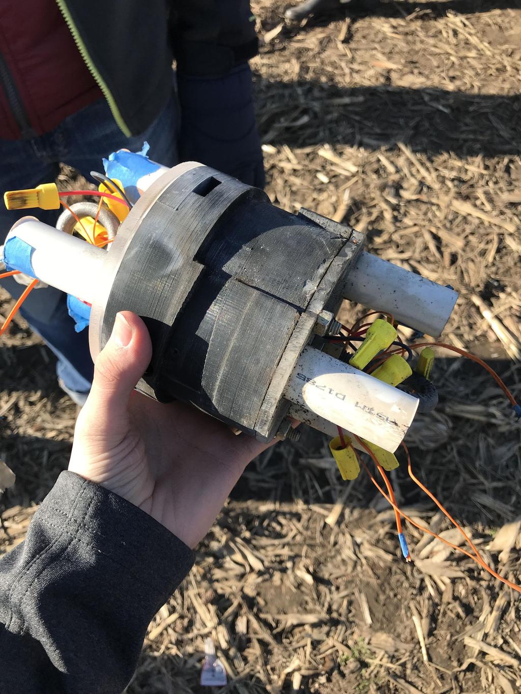
13 Final Recovery Integration Located in the middle section of the rocket CRAM screws into custom 3D printed mount Mount is epoxied and screwed into rocket body Eye bolts through bulkheads attached to CRAM allow attachment of shock cords and parachutes Shear pins hold sections of the rocket together and are sheared by charges in CRAM

14 Final Fin Design Material: Birch Plywood Height above body: 6 in Integration into fin can through 0.25 in slots using Rocketpoxy Parallelogram shape for greater stability and flutter prevention


15 Final Motor Choice: Cesaroni L-1395-BS Diameter: 2.95 inches Average Thrust: 314 lbf Length: inches Peak Thrust: lbf Total Weight: 9.46 lbs Total Impulse: lbf*s Thrust to Weight: 8.58 Burn Time: 3.51 s


16 Final Motor Mount Design 26.5 in Motor Mount Tube flush with fin can 32.5 in Fin Can Tube Capping Bulkhead 3 Centering Rings API Quick-Change Retention System

17 Final Rail Buttons 12 ft long 1.5 in wide rail Airfoil rail buttons Mounted 1.3 in from fin can at 0.5 in and in from rear of vehicle
18 Other Key Design Features Deployable Rover Payload Upon landing, deploy a rover that will travel a distance of five feet from the vehicle and deploy solar panels Air Braking System Air Braking Tabs will deploy based on an algorithm to make projected apogee as close to 5280 ft. as possible Flight Plan Ignition, burnout, ABP activated, apogee reached/drogue deployment, main deployment, landing, deployable rover activation, recovery
19 Simulations and Stability Stability Margin OpenRocket prediction: 2.86 body tube diameters Rocksim prediction: 3.01 body tube diameters
20 Simulations and Stability Velocity off the rod: 63.5 ft/s Maximum Acceleration: 245 ft/s^2 Apogee Predictions: 5 mph winds: 5404 ft. 10 mph winds: 5372 ft. 15 mph winds: 5333 ft. 20 mph winds: 5268 ft. CD Averages During engine burn: 0.28 After burnout: 0.30
21 Mass Statement Component Mass (oz) Nose Cone 31.2 Rover Payload Section Recovery Section ABP Section Fin Can Motor 117 Total Weight (46.64 lbs)
22 Full Scale Test Flight 136 inches long 7.74 inch fore outer diameter, 5.54 aft outer diameter Cesaroni L1115 Launch successful, recovery malfunction Main deployment at apogee Drift of ~0.9 miles Nose cone fell from 5765 feet
23 Full Scale Launch Results Apogee predictions off by approximately 20 feet. Second test launch day scheduled for March 17th This will test the Air Braking System and Deployable Rover Payload Will also test the rocket on the competition motor: Cesaroni L1395
24 Status of Requirement Verification Completed OpenRocket/Rocksim simulations Subscale launch on December 2nd, 2017 Altimeters tested in subscale flight Vehicle design and motor choice Recovery system design and sizing Stability of vehicle confirmed Full scale launch March 3rd, 2018 Component tests, shake tests In Progress Continued testing of recovery system Not Completed Second full scale test flight on March 17th, 2018 Air Braking System verified to decrease apogee to 5280 feet
25 Vehicle Test Plans and Procedures Completed Shake and impact tests of payload and body tube integration Initial black powder testing In Progress Refined black powder testing Not Completed Second full scale test flight on March 17th, 2018
26 Contents Overview Vehicle Design Recovery Subsystem Experimental Payloads Deployable Rover Payload Air Braking System Safety and Testing

27 Parachute Sizes and Descent Rates: Drogue Parachute: 24 Helical Nylon Deployed at Apogee Descent Velocity: 78 ft/s Rocket Weight vs Descent Velocity

28 Parachute Sizes and Descent Rates: Main Parachute: 144 Helical Nylon Deployed at 650 ft Descent Velocity: 13 ft/s Rocket Weight vs Descent Velocity
29 Mission performance predictions Kinetic Energy (ft-lbf) Flight phase Velocity (ft/s) Total rocket (723.5 oz) Fin can (321.7 oz) Motor burnout ,000 94,600 Apogee/droge deployment Main deployment Landing

30 Recovery System Tests Direct E-Match Tests LED Altimeter Simulation Testing E-Match Altimeter Simulation Trial Type Number of Trial Attempts Number of Trial Successes Battery directly to e-match Altimeter simulation to LED Altimeter simulation to e-match 9 10 LED Altimeter Test Setup

31 Recovery System Tests, cont. Altimeter Arming Procedure Ensures proper connection of E-Matches to altimeter Altimeter Shake Test Black Powder/Shear Pin 3 tests before launch Black Powder Testing Setup

32 Recovery Subsystem Overview


33 Recovery Subsystem Overview CRAM is inserted into body tube using screw to lock mechanism Twists into body tube using a 3D-printed coupler Secured by three screws that go through body tube, coupler, and CRAM to prevent untwisting during flight
34 Recovery Subsystem Dimensions Main Parachute: 12 ft diameter with a bleed hole Drogue Parachute: 2 ft diameter with a bleed hole Shock cords (2x): 42 ft length, 9/16 width CRAM: 4.98 diameter, 8.5 length

35 Integration Retaining screws secure CRAM to coupler and body tube Eyebolts are used to connect the CRAM to the rest of the vehicle
36 Contents Overview Vehicle Design Recovery Subsystem Experimental Payloads Deployable Rover Payload Air Braking System Safety and Testing
37 Deployable Rover: Summary Objective Remotely deploy rover upon landing Unfold two sets of solar panels once cleared from the rocket Terms of Success Autonomously drives five feet away from the rocket Solar panels unfold and provide measurable power to the rover The rover will be reusable within the same launch day
38 Deployable Rover: Design Overview Located directly below the nose cone Remotely deploy via a radio ground station and two black powder ejection charges The rover is able to drive in an inverted orientation Body of the rover is machined HDPE with 3D printed mounts for components Detects objects via LiDAR sensor Set of folded solar panels driven by a servo motor.

39 Solar Panels Set of folding solar panels mounted to center of rover and 2 extending rods, driven by a servo motor. Extends upon exit from body tube to triple surface area of solar array. Electrical functionality is verified by a resistor placed on the board powered only by the solar cells.
 Electronics")

40 Deployment System Signal sent to initiate nose cone ejection 1 g black powder above and below rover (redundant) Electronics receiving signal now on rover itself Rover receives signal to retract securing racks Drives out from tracks in body tube to spring-loaded ramp


41 Wheels and Motors Customized 3D printed hubs Goolsky FY-CL01 tires Lego Power functions XL motors provide more torque 220 rpm unloaded lbf in at 600mA

42 Electronics - Sensors LoRa Long Range Low Power Wireless communications Multi-stage testing Computer to computer Computer to PIC GPS Used to track position throughout flight and deployment Tested with Salae logic analyzer Verify cold start time Ensure correct GPS coordinates Bluetooth Used to triangulate position with respect to each section of the rocket Tested using NRF connect to ensure that the drop off is adequate to calculate distance Altimeter/LiDAR/Gyroscope Used to gather flight data and for object avoidance Created I2C test code and printed output to a terminal

43 Electronics-Powertrain Motor Drivers Uses same chip as normal lego XL drivers Tested with modified lego motors Battery circuits Two 3.4V nominal batteries Circuits using linear regulators switch to 3.3V and 5V for use by the other boards
44 Rover Assembly Step 1: Creating Parts Mill body, cut racks, and 3D print mounts Drill and tap holes for mounts on body Step 2: Structural Assembly Attach mounts and components within with nylon screws Attach wheels with lego connectors and reinforce with epoxy. Attach wires for electronic components and secured close to body with zip-ties.
")

45 Rover Integration with Rocket Involved epoxying the tracks (with hinges for ramps) and mounting blocks with a milled alignment tool. Connected to the transition section with RocketPoxy

46 Deployment System Assembly Three bulkheads were initially milled. 2 PVC tubes were epoxied to the base bulkhead, and the other two bulkheads were epoxied into the nose cone. Holes were milled in the middle bulkhead to allow the PVC tubes to pass through. 3D printed rover mounts were epoxied to the body tube using the rover rack extension to ensure precise placement.


47 Rover System Testing Shake Test - Rover must be fixed along the securing mounts inside the launch vehicle to prevent motion in all directions Object Avoidance and Rocket Detection Test
48 Black Powder Ejection Testing Optimize the number of shear pins and black powder 8 shear pins 1 gram of black powder per pipe
49 NASA Requirements Requirement Requirement will be met by Verification Teams will design a custom rover that will deploy from the internal structure of the launch vehicle The rover is built from a combination of custom milled HDPE, 3D printed components and commercially available parts. The rover is secured directly below the nose cone and is deployed using a radio controlled ground station. At landing, the team will remotely activate a trigger to deploy the rover from the rocket A LoRa module is used for wireless communication to the rover. This module will interface with a laptop base station to initiate the deployment sequence upon a safe landing After deployment, the rover will autonomously move at least 5ft (in any direction) from the launch vehicle. Bluetooth chips are placed throughout the body of the rocket to provide triangulation to the rover. Once the rover has reached its final destination, it will deploy a set of foldable solar cell panels When the rover registers the safe distance from the rocket a servomotor drives the solar array out. The array will triple in surface area due to the folds. A fully constructed rover payload was present for the full scale launch Securing system tested with shake test and full scale launch The LoRa module was tested without ejection charges Ground testing was performed to optimize the amount of black powder used Full scale launch to test the entire system will be performed in late March Isolated bluetooth tests were performed prior to construction Ground tests were performed to ensure the placement of the chips allowed for accurate triangulation Full scale flight test performed in late March Prior to the full scale test flight the deployment sequence was tested and confirmed using a dummy array. The full scale flight tested the entire rover sequence including the solar panels.
50 Team Requirements Requirement Requirement will be met by The nose cone will be deployed via black powder charges allowing the rover to drive out of the rocket Two PVC pipes mounted at the rear of the payload will contain two grams of black powder (one gram in each pipe). The base station initiates the deployment sequence that ignites e-matches and sets of the ejection charges. Shunt pins are in place to prevent misfire before the rocket is loaded onto the pad Oversized wheels provide clearance in both orientations. The electronics are configured for driving in either orientation. Upon landing, the rover will be capable of driving in an inverted position Verification Ground tests were performed to optimize the number of shear pins securing the nose cone and the amount of black powder used. Full Scale Launch verified the deployment - to be done in late March A redundant system is in place to ensure the ignition of the ejection charges. The rover was tested in both orientations and successfully avoided objects and detected the rocket Rover successfully drove and maneuvered on rough terrain similar to the expected competition terrain
51 Contents Overview Vehicle Design Recovery Subsystem Experimental Payloads Deployable Rover Payload Air Braking System Safety and Testing
52 Air Braking System: Overview Four variable extension drag tabs will induce an additional, controllable drag force on the rocket The drag tabs will be controlled by a crank-slider mechanism, driven by a central shaft connected to two servo motors The servo motors will be controlled by a microcontroller running a control code Separate power sources for the servos and microcontroller The control code uses a combination of barometer and accelerometer data along with PID control to determine tab extension

53 Air Braking System: Overview
54 Air Braking System: Drag Tabs Four variable extension drag tabs cut via CNC routing Made of 0.25 in. thick UHMW Tapped holes for connection with M3 bolts Tabs machined smaller than designed to allow for tolerances in the fit Extra volume removed from a top corner of each tab to reduce interference with the tie rods
55 Air Braking System: Mechanism Crank-slider design with central, driven shaft When assembled, the tie rods interfered with the tabs at full retraction at the corners Material was milled from these corners, allowing full retraction of the tabs

56 Air Braking System: Mechanism Tie rods connect the crosspiece to the tabs The anticipated spacers between each of the tie ends were not necessary to achieve desired length Tie ends were milled to length and thread locked on a threaded rod. Crosspiece that is driven by a central shaft Piece cut from UHMW Tapped holes for connection with M3 bolts Broached keyhole to transmit shaft torque


57 Air Braking System: Electronics Arduino MKR Zero Processes sensor data in-flight Controls tab movements Built-in SD card reader 3.3 V Operating Voltage 32 KB SRAM 48 MHz Clock Speed Adafruit Lithium Ion Battery Powers Arduino -- more than enough battery life 2000 mah capacity 3.7 V Nominal Voltage


58 Air Braking System: Electronics Two Power HD 1235 servo motors actuate the system 7.4 V operating voltage Combine for a maximum torque of 1120 oz-in Two 7.4 V Tenergy lithium-ion batteries wired in parallel are used to power the servo motors 2600 mah capacity Measured 8.4 V at full charge

59 Air Braking System: Electronics Three molex connectors soldered to the printed circuit board One floating molex connector to add removability to switch No on-board voltage division necessary due to separate power supplies Use of shrink wrap, electrical tape, and hot glue to prevent shorts, increase connection strength


60 Air Braking System: Electronics Two primary flight sensors: ADXL 345 accelerometer and BMP 280 barometer; both have sufficient range and precision for the flight environment Both sensors are used to calculate rocket velocity, track flight progress P3 R25W Potentiometer attached to the servo gearbox allows the control code to monitor if the mechanism has jammed
61 Air Braking System: Control Code Before launch, algorithm toggles between armed and disarmed states with an onboard button The drag control algorithm activates after motor burnout Velocity is calculated using barometer data before burnout, then accelerometer data after burnout The microprocessor compares the rocket s velocity to a pre-calculated ideal velocity at the current altitude This error information is fed to a PID controller to command the servo motor which controls tab extension until apogee An onboard potentiometer allows the code to monitor gearbox jams


62 Air Braking System: Integration The electronic components are secured to four HDPE decks Four steel threaded rods hold the system together by connecting the integration decks in sequence Each deck is separated from the next by plastic spacers on the threaded rods Four vehicle integration rods run through the system, with lock nuts to secure system in the fin can
63 Air Braking System: Testing and Verification Mechanism Ground Testing Integration Ground Testing Verified that the servo motors functioned properly and were controllable Power System Ground Testing Performed shake test to determine vibrational integrity of system Servo Motor Ground Testing Verified that drag tabs extended when central shaft turned No jams in the motion Verified that batteries functioned properly Determined loading on the batteries when operating the servo motors PCB Ground Testing Tested connections on PCB
64 Air Braking System: Testing and Verification Sensor Ground Testing Determined noise levels in sensors Control Code Ground Testing Tested response of the system to a simulated flight Tested response of the system to a jammed mechanism Full Scale Flight Test Collect flight and system performance data Determine the effectiveness of the system Improve the system as needed
65 Contents Overview Vehicle Design Recovery Subsystem Experimental Payloads Deployable Rover Payload Air Braking System Safety and Testing
66 Safety & Testing Safety is a live document, always in flux in order to be able to accomodate and account for any and all failures Safety is essential to mitigate risk of critical accidents to team members, general audience, and the launch itself. Changes since CDR: Vast elaboration on FMEA tables for the Vehicle section and Recovery Payload. Potential hazards were added to the launch checklists in order to emphasize safety at the most critical moments before, during, and after the launch
67 Safety & Testing A detailed pre-launch checklist serves as a functional guide for the final assembly process of the rocket. Possible hazards have been identified in launch procedures to help mitigate risks even further. A repeatable launch procedure, with an emphasis on hazardous steps and what to do in case of an emergency, is convenient and beneficial when minimizing risk of failure at the launch site. Post-launch procedure allow for a safe retrieval of the rocket without damaging or severely altering the environment
68 Environmental Concerns It is critical to consider environmental concerns associated with a launch. Environmental hazards that might affect the rocket fall into three categories with some overlap 1. Vehicle integrity hazards 2. Avionics integrity hazards 3. Vehicle behavior hazards Hazards will be mitigated by performing launch when environmental parameters are within acceptable bounds
69 Environmental Concerns Conversely, the rocket can affect its environment negatively, this too must be mitigated Hazards to environment fall within two basic categories 1. Pollution Contamination of groundwater Atmospheric contamination 2. Harm to flora and fauna Fires due to launch Unexpected disturbance of animal habitats and ecosystems during course of launch
70 Failure Mode Analysis Potential hazards and failure modes for vehicle were analyzed through FMEA table. Classified through Risk Assessment Codes (RAC) Technical failure modes were divided into six categories Proposed mitigations and controls for each risk
71 Personnel Safety: General Every member s safety is of utmost importance Safety factors are considered from assembly to launch We will prioritize prevention over intervention Basic precautions: Appropriate safety gear will be worn at all times Only trained members of the team will operate hazardous equipment Safe distances will be kept from all explosives and dangerous devices Appropriate levels of caution will be maintained
72 Personnel Safety: Chemical Exposure to hazardous substances Different substances are dangerous on different timescales Ammonium Perchlorate Immediately rinse with water Handle with gloves Lead Wash hands after soldering Avoid eating/drinking while soldering Fumes Ensure adequate ventilation Battery Acid Ensure that batteries are properly maintained and operated Flush the affected area with either water or sodium bicarbonate depending on the acid Epoxy Immediately rinse area with soap and water
73 Questions?
FLIGHT READINESS REVIEW TEAM OPTICS
 FLIGHT READINESS REVIEW TEAM OPTICS LAUNCH VEHICLE AND PAYLOAD DESIGN AND DIMENSIONS Vehicle Diameter 4 Upper Airframe Length 40 Lower Airframe Length 46 Coupler Band Length 1.5 Coupler Length 12 Nose
Critical Design Review
 Critical Design Review University of Illinois at Urbana-Champaign NASA Student Launch 2017-2018 Illinois Space Society 1 Overview Illinois Space Society 2 Launch Vehicle Summary Javier Brown Illinois Space
NASA SL - NU FRONTIERS. PDR presentation to the NASA Student Launch Review Panel
 NASA SL - NU FRONTIERS PDR presentation to the NASA Student Launch Review Panel 1 Agenda Launch Vehicle Overview Nose Cone Section Payload Section Lower Avionic Bay Section Booster Section Motor Selection
CRITICAL DESIGN REVIEW. University of South Florida Society of Aeronautics and Rocketry
 CRITICAL DESIGN REVIEW University of South Florida Society of Aeronautics and Rocketry 2017-2018 AGENDA 1. Launch Vehicle 2. Recovery 3. Testing 4. Subscale Vehicle 5. Payload 6. Educational Outreach 7.
Presentation Outline. # Title # Title
 CDR Presentation 1 Presentation Outline # Title # Title 3 4 5 6 7 8 9 10 11 12 13 14 15 16 17 18 19 20 21 22 23 24 25 26 Team Introduction Vehicle Overview Vehicle Dimensions Upper Body Section Payload
Jordan High School Rocketry Team. A Roll Stabilized Video Platform and Inflatable Location Device
 Jordan High School Rocketry Team A Roll Stabilized Video Platform and Inflatable Location Device Mission Success Criteria No damage done to any person or property. The recovery system deploys as expected.
Flight Readiness Review
 Flight Readiness Review University of Illinois at Urbana-Champaign NASA Student Launch 2017-2018 Illinois Space Society 1 Overview Illinois Space Society 2 Launch Vehicle Summary Javier Brown Illinois
CRITICAL DESIGN PRESENTATION
 CRITICAL DESIGN PRESENTATION UNIVERSITY OF SOUTH ALABAMA LAUNCH SOCIETY BILL BROWN, BEECHER FAUST, ROCKWELL GARRIDO, CARSON SCHAFF, MICHAEL WIESNETH, MATTHEW WOJCIECHOWSKI ADVISOR: CARLOS MONTALVO MENTOR:
Georgia Tech NASA Critical Design Review Teleconference Presented By: Georgia Tech Team ARES
 Georgia Tech NASA Critical Design Review Teleconference Presented By: Georgia Tech Team ARES 1 Agenda 1. Team Overview (1 Min) 2. 3. 4. 5. 6. 7. Changes Since Proposal (1 Min) Educational Outreach (1 Min)
Preliminary Design Review. Cyclone Student Launch Initiative
 Preliminary Design Review Cyclone Student Launch Initiative Overview Team Overview Mission Statement Vehicle Overview Avionics Overview Safety Overview Payload Overview Requirements Compliance Plan Team
Auburn University. Project Wall-Eagle FRR
 Auburn University Project Wall-Eagle FRR Rocket Design Rocket Model Mass Estimates Booster Section Mass(lb.) Estimated Upper Section Mass(lb.) Actual Component Mass(lb.) Estimated Mass(lb.) Actual Component
Presentation Outline. # Title
 FRR Presentation 1 Presentation Outline # Title 3 4 5 6 7 8 9 10 11 12 13 14 15 16 17 18 19 20 21 22 23 24 Team Introduction Mission Summary Vehicle Overview Vehicle Dimensions Upper Body Section Elliptical
Illinois Space Society Flight Readiness Review. University of Illinois Urbana-Champaign NASA Student Launch March 30, 2016
 Illinois Space Society Flight Readiness Review University of Illinois Urbana-Champaign NASA Student Launch 2015-2016 March 30, 2016 Team Managers Project Manager: Ian Charter Structures and Recovery Manager:
UC Berkeley Space Technologies and Rocketry Preliminary Design Review Presentation. Access Control: CalSTAR Public Access
 UC Berkeley Space Technologies and Rocketry Preliminary Design Review Presentation Access Control: CalSTAR Public Access Agenda Airframe Propulsion Payload Recovery Safety Outreach Project Plan Airframe
NASA - USLI Presentation 1/23/2013. University of Minnesota: USLI CDR 1
 NASA - USLI Presentation 1/23/2013 2013 USLI CDR 1 Final design Key features Final motor choice Flight profile Stability Mass Drift Parachute Kinetic Energy Staged recovery Payload Integration Interface
University of Notre Dame
 University of Notre Dame 2016-2017 Notre Dame Rocketry Team Critical Design Review NASA Student Launch Competition Roll Control and Fragile Object Protection Payloads Submitted January 13, 2017 365 Fitzpatrick
NASA USLI PRELIMINARY DESIGN REVIEW. University of California, Davis SpaceED Rockets Team
 NASA USLI 2012-13 PRELIMINARY DESIGN REVIEW University of California, Davis SpaceED Rockets Team OUTLINE School Information Launch Vehicle Summary Motor Selection Mission Performance and Predictions Structures
Auburn University Student Launch. PDR Presentation November 16, 2015
 Auburn University Student Launch PDR Presentation November 16, 2015 Project Aquila Vehicle Dimensions Total Length of 69.125 inches Inner Diameter of 5 inches Outer Diameter of 5.25 inches Estimated mass
NASA SL Critical Design Review
 NASA SL Critical Design Review University of Alabama in Huntsville 1 LAUNCH VEHICLE 2 Vehicle Summary Launch Vehicle Dimensions Fairing Diameter: 6 in. Body Tube Diameter: 4 in. Mass at lift off: 43.8
Overview. Mission Overview Payload and Subsystems Rocket and Subsystems Management
 MIT ROCKET TEAM Overview Mission Overview Payload and Subsystems Rocket and Subsystems Management Purpose and Mission Statement Our Mission: Use a rocket to rapidly deploy a UAV capable of completing search
PRELIMINARY DESIGN REVIEW
 PRELIMINARY DESIGN REVIEW 1 1 Team Structure - Team Leader: Michael Blackwood NAR #101098L2 Certified - Safety Officer: Jay Nagy - Team Mentor: Art Upton NAR #26255L3 Certified - NAR Section: Jackson Model
University Student Launch Initiative
 University Student Launch Initiative HARDING UNIVERSITY Flight Readiness Review March 31, 2008 Launch Vehicle Summary Size: 97.7 (2.5 meters long), 3.1 diameter Motor: Contrail Rockets 54mm J-234 Recovery
GIT LIT NASA STUDENT LAUNCH PRELIMINARY DESIGN REVIEW NOVEMBER 13TH, 2017
 GIT LIT 07-08 NASA STUDENT LAUNCH PRELIMINARY DESIGN REVIEW NOVEMBER TH, 07 AGENDA. Team Overview (5 Min). Educational Outreach ( Min). Safety ( Min) 4. Project Budget ( Min) 5. Launch Vehicle (0 min)
NASA s Student Launch Initiative :
 NASA s Student Launch Initiative : Critical Design Review Payload: Fragile Material Protection 1 Agenda 1. Design Overview 2. Payload 3. Recovery 4. 5. I. Sub-Scale Predictions II. Sub-Scale Test III.
Flight Readiness Review March 16, Agenda. California State Polytechnic University, Pomona W. Temple Ave, Pomona, CA 91768
 Flight Readiness Review March 16, 2018 Agenda California State Polytechnic University, Pomona 3801 W. Temple Ave, Pomona, CA 91768 Agenda 1.0 Changes made Since CDR 2.0 Launch Vehicle Criteria 3.0 Mission
Wichita State Launch Project K.I.S.S.
 Wichita State Launch Project K.I.S.S. Benjamin Russell Jublain Wohler Mohamed Moustafa Tarun Bandemagala Outline 1. 2. 3. 4. 5. 6. 7. Introduction Vehicle Overview Mission Predictions Payload Design Requirement
Preliminary Design Review. California State University, Long Beach USLI November 13th, 2017
 Preliminary Design Review California State University, Long Beach USLI November 13th, 2017 System Overview Launch Vehicle Dimensions Total Length 108in Airframe OD 6.17in. ID 6.00in. Couplers OD 5.998in.
Critical Design Review Report
 Critical Design Review Report I) Summary of PDR report Team Name: The Rocket Men Mailing Address: Spring Grove Area High School 1490 Roth s Church Road Spring Grove, PA 17362 Mentor: Tom Aument NAR Number
The University of Toledo
 The University of Toledo Project Kronos Preliminary Design Review 11/03/2017 University of Toledo UT Rocketry Club 2801 W Bancroft St. MS 105 Toledo, OH 43606 Contents 1 Summary of Proposal... 6 1.1 Team
Flight Readiness Review Addendum: Full-Scale Re-Flight. Roll Induction and Counter Roll NASA University Student Launch.
 Flight Readiness Review Addendum: Full-Scale Re-Flight Roll Induction and Counter Roll 2016-2017 NASA University Student Launch 27 March 2017 Propulsion Research Center, 301 Sparkman Dr. NW, Huntsville
Project NOVA
 Project NOVA 2017-2018 Our Mission Design a Rocket Capable of: Apogee of 5280 ft Deploying an autonomous Rover Vehicle REILLY B. Vehicle Dimensions Total Length of 108 inches Inner Diameter of 6 inches
NASA SL Flight Readiness Review
 NASA SL Flight Readiness Review University of Alabama in Huntsville 1 LAUNCH VEHICLE 2 Vehicle Overview Vehicle Dimensions Diameter: 6 fairing/4 aft Length: 106 inches Wet Mass: 41.1 lbs. Center of Pressure:
NUMAV. AIAA at Northeastern University
 NUMAV AIAA at Northeastern University Team Officials Andrew Buggee, President, Northeastern AIAA chapter Dr. Andrew Goldstone, Faculty Advisor John Hume, Safety Officer Rob DeHate, Team Mentor Team Roster
Statement of Work Requirements Verification Table - Addendum
 Statement of Work Requirements Verification Table - Addendum Vehicle Requirements Requirement Success Criteria Verification 1.1 No specific design requirement exists for the altitude. The altitude is a
University of Illinois at Urbana-Champaign Illinois Space Society Student Launch Preliminary Design Review November 3, 2017
 University of Illinois at Urbana-Champaign Illinois Space Society Student Launch 2017-2018 Preliminary Design Review November 3, 2017 Illinois Space Society 104 S. Wright Street Room 18C Urbana, Illinois
University Student Launch Initiative
 University Student Launch Initiative HARDING UNIVERSITY Critical Design Review February 4, 2008 The Team Dr. Edmond Wilson Brett Keller Team Official Project Leader, Safety Officer Professor of Chemistry
NASA USLI Flight Readiness Review (FRR) Rensselaer Rocket Society (RRS)
 Rensselaer Rocket Society (RRS)") 2016-2017 NASA USLI Flight Readiness Review (FRR) Rensselaer Rocket Society (RRS) Rensselaer Polytechnic Institute 110 8th St Troy, NY 12180 Project Name: Andromeda Task 3.3: Roll Induction and Counter
2016-2017 NASA USLI Flight Readiness Review (FRR) Rensselaer Rocket Society (RRS) Rensselaer Polytechnic Institute 110 8th St Troy, NY 12180 Project Name: Andromeda Task 3.3: Roll Induction and Counter
Tacho Lycos 2017 NASA Student Launch Critical Design Review
 Tacho Lycos 2017 NASA Student Launch Critical Design Review High-Powered Rocketry Team 911 Oval Drive Raleigh NC, 27695 January 13, 2017 Table of Contents Table of Figures:... 8 Table of Appendices:...
Tripoli Rocketry Association Level 3 Certification Attempt
 Tripoli Rocketry Association Level 3 Certification Attempt Kevin O Classen 1101 Dutton Brook Road Goshen, VT 05733 (802) 247-4205 kevin@back2bed.com Doctor Fill Doctor Fill General Specifications Airframe:
Flight Readiness Review Report NASA Student Launch Florida International University American Society of Mechanical Engineers (FIU-ASME)
") Flight Readiness Review Report 2014-2015 NASA Student Launch Florida International University American Society of Mechanical Engineers (FIU-ASME) Florida International University Engineering Center College
Flight Readiness Review Report 2014-2015 NASA Student Launch Florida International University American Society of Mechanical Engineers (FIU-ASME) Florida International University Engineering Center College
Critical Design Review Report NASA Student Launch Florida International University American Society of Mechanical Engineers (FIU-ASME)
") Critical Design Review Report 2014-2015 NASA Student Launch Florida International University American Society of Mechanical Engineers (FIU-ASME) Florida International University Engineering Center College
Critical Design Review Report 2014-2015 NASA Student Launch Florida International University American Society of Mechanical Engineers (FIU-ASME) Florida International University Engineering Center College
Critical Design Review
 Critical Design Review 1/27/2017 NASA Student Launch Competition 2016-2017 California State Polytechnic University, Pomona 3801 W Temple Ave, Pomona, CA 91768 1/27/2017 California State Polytechnic University,
Cornell Rocketry Team. NASA Student Launch Competition CORNELL ROCKETRY TEAM
 2015-2016 CORNELL ROCKETRY TEAM Presentation Centennial Challenge MAV Participant NASA Student Launch Competition LAUNCH VEHICLE GENERAL DIMENSIONS Airframe Tubing: OD = 3.98 in ID = 3.9 in Couplers: OD
Tacho Lycos 2017 NASA Student Launch Flight Readiness Review
 Tacho Lycos 2017 NASA Student Launch Flight Readiness Review High-Powered Rocketry Team 911 Oval Drive Raleigh NC, 27695 March 6, 2017 Table of Contents Table of Figures... 9 Table of Appendices... 11
HPR Staging & Air Starting By Gary Stroick
 Complex Rocket Design Considerations HPR Staging & Air Starting By Gary Stroick 1. Tripoli Safety Code 2. Technical Considerations 3. Clusters/Air Starts 4. Staging 5. Summary 2 1. Complex High Power Rocket.
Pegasus II. Tripoli Level 3 Project Documentation. Brian Wheeler
 Pegasus II Tripoli Level 3 Project Documentation Brian Wheeler Contents: A. Design Overview B. Booster Construction C. Electronics Bay (Mechanical) Construction D. Nose Cone Construction E. Recovery System
AUBURN UNIVERSITY STUDENT LAUNCH. Project Nova. 211 Davis Hall AUBURN, AL Post Launch Assessment Review
 AUBURN UNIVERSITY STUDENT LAUNCH Project Nova 211 Davis Hall AUBURN, AL 36849 Post Launch Assessment Review April 19, 2018 Table of Contents Table of Contents...2 List of Tables...3 Section 1: Launch Vehicle
LEVEL 3 BUILD YELLOW BIRD. Dan Schwartz
 LEVEL 3 BUILD YELLOW BIRD Dan Schwartz This entire rocket is built using the same techniques I use for my nose cones, a central airframe tube for compression strength and rings of high compression styrofoam
Team Air Mail Preliminary Design Review
 Team Air Mail Preliminary Design Review 2014-2015 Space Grant Midwest High-Power Rocket Competition UAH Space Hardware Club Huntsville, AL Top: Will Hill, Davis Hunter, Beth Dutour, Bradley Henderson,
PROJECT AQUILA 211 ENGINEERING DRIVE AUBURN, AL POST LAUNCH ASSESSMENT REVIEW
 PROJECT AQUILA 211 ENGINEERING DRIVE AUBURN, AL 36849 POST LAUNCH ASSESSMENT REVIEW APRIL 29, 2016 Motor Specifications The team originally planned to use an Aerotech L-1520T motor and attempted four full
Pre-Flight Checklist for SLIPSTICK III
 Advanced Planning 1 Schedule a Check that waivers are available at the intended launch site and date. b Check weather forecast for wind and temperature conditions at the site. c Have TAP members approved
AUBURN UNIVERSITY STUDENT LAUNCH PROJECT NOVA II. 211 Davis Hall AUBURN, AL CDR
 AUBURN UNIVERSITY STUDENT LAUNCH PROJECT NOVA II 211 Davis Hall AUBURN, AL 36849 CDR January 10, 2019 Contents List of Tables...7 List of Figures...9 1 CDR Report Summary...12 1.1 Payload Deployable Rover...12
Presentation 3 Vehicle Systems - Phoenix
 Presentation 3 Vehicle Systems - Phoenix 1 Outline Structures Nosecone Body tubes Bulkheads Fins Tailcone Recovery System Layout Testing Propulsion Ox Tank Plumbing Injector Chamber Nozzle Testing Hydrostatic
USLI Critical Design Report
 UNIVERSITY OF MINNESOTA TWIN CITIES 2011 2012 USLI Critical Design Report University Of Minnesota Team Artemis 1/23/2012 Critical Design Report by University of Minnesota Team Artemis for 2011-2012 NASA
Illinois Space Society University of Illinois Urbana Champaign Student Launch Maxi-MAV Preliminary Design Review November 5, 2014
 Illinois Space Society University of Illinois Urbana Champaign Student Launch 2014-2015 Maxi-MAV Preliminary Design Review November 5, 2014 Illinois Space Society 104 S. Wright Street Room 321D Urbana,
Madison West High School Green Team
 Madison West High School Green Team The Effect of Gravitational Forces on Arabidopsis Thaliana Development Flight Readiness Review The Vehicle Mission Performance Criteria Successful two stage flight Altitude
Northwest Indian College Space Center USLI Critical Design Review
 2012-2013 Northwest Indian College Space Center USLI Critical Design Review Table of Contents, Tables, and Figures I.0 CDR Report Summary... 1 I.1 Team Summary... 1 I.2 Launch Vehicle Summary... 1 I.2a
Rocketry Projects Conducted at the University of Cincinnati
 Rocketry Projects Conducted at the University of Cincinnati 2009-2010 Grant Schaffner, Ph.D. (Advisor) Rob Charvat (Student) 17 September 2010 1 Spacecraft Design Course Objectives Students gain experience
Rocket Design. Tripoli Minnesota Gary Stroick. February 2010
 Rocket Design Tripoli Minnesota Gary Stroick February 2010 Purpose Focus is on designing aerodynamically stable rockets not drag optimization nor construction techniques! Copyright 2010 by Gary Stroick
CNY Rocket Team Challenge. Basics of Using RockSim 9 to Predict Altitude for the Central New York Rocket Team Challenge
 CNY Rocket Team Challenge Basics of Using RockSim 9 to Predict Altitude for the Central New York Rocket Team Challenge RockSim 9 Basics 2 Table of Contents A. Introduction.p. 3 B. Designing Your Rocket.p.
NASA Student Launch W. Foothill Blvd. Glendora, CA Artemis. Deployable Rover. November 3rd, Preliminary Design Review
 2017 2018 NASA Student Launch Preliminary Design Review 1000 W. Foothill Blvd. Glendora, CA 91741 Artemis Deployable Rover November 3rd, 2017 Table of Contents General Information... 9 1. School Information...
Critical Design Review
 AIAA Orange County Section Student Launch Initiative 2011-2012 Critical Design Review Rocket Deployment of a Bendable Wing Micro-UAV for Data Collection Submitted by: AIAA Orange County Section NASA Student
NASA Student Launch College and University. Preliminary Design Review
 2017-2018 NASA Student Launch College and University Preliminary Design Review Institution: United States Naval Academy Mailing Address: Aerospace Engineering Department United States Naval Academy ATTN:
SpaceLoft XL Sub-Orbital Launch Vehicle
 SpaceLoft XL Sub-Orbital Launch Vehicle The SpaceLoft XL is UP Aerospace s workhorse space launch vehicle -- ideal for significant-size payloads and multiple, simultaneous-customer operations. SpaceLoft
NASA University Student Launch Initiative (Sensor Payload) Final Design Review. Payload Name: G.A.M.B.L.S.
 Final Design Review. Payload Name: G.A.M.B.L.S.") NASA University Student Launch Initiative (Sensor Payload) Final Design Review Payload Name: G.A.M.B.L.S. CPE496-01 Computer Engineering Design II Electrical and Computer Engineering The University of
NASA University Student Launch Initiative (Sensor Payload) Final Design Review Payload Name: G.A.M.B.L.S. CPE496-01 Computer Engineering Design II Electrical and Computer Engineering The University of
NORTHEASTERN UNIVERSITY
 NORTHEASTERN UNIVERSITY POST-LAUNCH ASSESSMENT REVIEW NORTHEASTERN UNIVERSITY USLI TEAM APRIL 27TH 2018 Table of Contents 1. Summary 2 1.1 Team Summary 2 1.2 Launch Summary 2 2. Launch Vehicle Assessment
The University of Toledo
 The University of Toledo Project Cairo Preliminary Design Review 10/08/2016 University of Toledo UT Rocketry Club 2801 W Bancroft St. MS 105 Toledo, OH 43606 Contents 1 Summary of Preliminary Design Review...
First Nations Launch Rocket Competition 2016
 First Nations Launch Rocket Competition 2016 Competition Date April 21-22, 2016 Carthage College Kenosha, WI April 23, 2016 Richard Bong Recreational Park Kansasville, WI Meet the Team Wisconsin Space
Preliminary Design Review
 Preliminary Design Review November 16, 2016 11/2016 California State Polytechnic University, Pomona 3801 W Temple Ave, Pomona, CA 91768 Student Launch Competition 2016-2017 1 Agenda 1.0 General Information
Electronic Deployment
 Electronic Deployment and a little bit of recovery too! By: Gerald Meux, Jr. NAR and TRA Level 3 1-3-11 8/28/2014 Electronic Deployment - Gerald Meux, Jr. 1 Table of Contents 8/28/2014 Electronic Deployment
Student Launch. Enclosed: Preliminary Design Review. Submitted by: Rocket Team Project Lead: David Eilken
 University of Evansville Student Launch Enclosed: Preliminary Design Review Submitted by: 2016 2017 Rocket Team Project Lead: David Eilken Submission Date: November 04, 2016 Payload: Fragile Material Protection
University of North Dakota Department of Physics Frozen Fury Rocketry Team
 University of North Dakota Department of Physics Frozen Fury Rocketry Team NASA Student Launch Initiative Flight Readiness Review - Report Submitted by: The University of North Dakota Frozen Fury Rocketry
USLI Flight Readiness Review
 UNIVERSITY OF MINNESOTA TWIN CITIES 2011 2012 USLI Flight Readiness Review University Of Minnesota Team Artemis 3/26/2012 Flight Readiness Report prepared by University of Minnesota Team Artemis for 2011-2012
Post Launch Assessment Review
 AIAA Orange County Section Student Launch Initiative 2011-2012 Post Launch Assessment Review Rocket Deployment of a Bendable Wing Micro-UAV for Data Collection Submitted by: AIAA Orange County Section
NASA SL Preliminary Design Review
 NASA SL Preliminary Design Review University of Alabama in Huntsville 1 Mission Summary Design, fabricate, test and fly a rocket and payload to 1 mile in altitude Deploy a rover upon landing to autonomously
Skill Level 3 Average Skills Needed. Made In USA. Kit #04997 Skill Level 4. Zephyr Parts List
 Kit #04997 Skill Level 4 Made In USA Zephyr Parts List Item # Item Name Qty 10137 Engine Mount Tube (AT-38/11) 1 10218 Airframe Body Tube (AT-98/18) 4" Thick Wall 1 10219 Airframe Body Tube (AT-98/18)
Rover Delivery NASA University Student Launch Initiative Post-Launch Assessment Review. Charger Rocket Works.
 Rover Delivery 2017-2018 NASA University Student Launch Initiative Post-Launch Assessment Review Charger Rocket Works April 27 th, 2018 Propulsion Research Center 1030 John Wright Drive NW, Huntsville,
This Week. Next Week 4/7/15
 E80 Spring 2015 This Week! Transfer breadboard circuit to PC board.! Verify everything still works.! Get data logger working.! Pass off consists of: " Power PC board with data logger & start logging. "
Florida A & M University. Flight Readiness Review. 11/19/2010 Preliminary Design Review
 Florida A & M University Flight Readiness Review 11/19/2010 Preliminary Design Review 1 Overview Team Summary ~~~~~~~~~~~~~~~~~~~~~~~~~~~~~~ ~~~~~~~~ Vehicle Criteria ~~~~~~~~~~~~~~~~~~~~~~~~~~~~~~ ~~~~~~~~
Critical Design Review
 Harding University University Student Launch Initiative Team Critical Design Review January 29, 2007 The Flying Bison Sarah Christensen Project Leader Dr. Ed Wilson Faculty Supervisor Dr. James Mackey
University Student Launch Initiative Preliminary Design Review
 UNIVERSITY OF MINNESOTA TWIN CITIES 2012 2013 University Student Launch Initiative Preliminary Design Review Department of Aerospace Engineering and Mechanics 3/18/2013 2012-2013 University of Minnesota
THE UNIVERSITY OF AKRON
 THE UNIVERSITY OF AKRON College of Engineering 302 E Buchtel Ave Akron, OH 44325 September 20, 2017 NASA Student Launch Initiative Table of Contents 1. Adult Educators and Advisors... 4 2. Team Officials...
Innovating the future of disaster relief
 Innovating the future of disaster relief American Helicopter Society International 33rd Annual Student Design Competition Graduate Student Team Submission VEHICLE OVERVIEW FOUR VIEW DRAWING INTERNAL COMPONENTS
Tuskegee University Rocketry Club
 Tuskegee University Rocketry Club National Aeronautics and Space Administration Student Launch Initiative Preliminary Design Review Atmospheric Measurement and Aerodynamic Analysis TURC 2015-2016 NASA
Eric Kamber Harry Gooden Josh Westmoreland Billy Rigdon
 Comprehensive Design I - MECH 4240 Final Fall 2008 Eric Kamber Harry Gooden Josh Westmoreland Billy Rigdon Overview Projects Body and Panel Mounting Exhaust Hood Array Stage 1 Hood Array Stage 2 Belly
Warning! Before continuing further, please ensure that you have NOT mounted the propellers on the MultiRotor.
 Mission Planner Setup ( optional, do not use if you have already completed the Dashboard set-up ) Warning! Before continuing further, please ensure that you have NOT mounted the propellers on the MultiRotor.
CYCLONE STUDENT LAUNCH INITIATIVE
 NSL PROPOSAL September 19, 2018 CYCLONE STUDENT LAUNCH INITIATIVE 2018-19 Iowa State University 537 Bissell Rd. 1200 Howe Hall Ames, IA 50011 Table of Contents Table of Contents... 2 Table of Figures...
ADVANCED MODEL ROCKET
 Division of RCS Rocket Components, Inc. Assembly and Operation Instructions BEFORE YOU BEGIN: ADVANCED MODEL ROCKET COMPLETED INITIATOR ADVANCED MODEL ROCKET 19911-8091 Rev. 8/12/04 Study the illustrations
Project WALL-Eagle Maxi-Mav Flight Readiness Review
 S A M U E L G I N N C O L L E G E O F E N G I N E E R I N G Auburn University Project WALL-Eagle Maxi-Mav Flight Readiness Review 2 Engineering Dr. Auburn, AL 36849 March 6th, 205 Table of Contents Section
Preliminary Design Review November 15, Agenda. California State Polytechnic University, Pomona W. Temple Ave, Pomona, CA 91768
 Preliminary Design Review November 15, 2017 Agenda California State Polytechnic University, Pomona 3801 W. Temple Ave, Pomona, CA 91768 Agenda 1.0 General Information 2.0 Launch Vehicle System Overview
NWIC Space Center s 2017 First Nations Launch Achievements
 NWIC Space Center s 2017 First Nations Launch Achievements On April 18, 2017, we were on two airplanes to Milwaukee, Wisconsin by 6:30 am for a long flight. There were 12 students, 3 mentors, 2 toddlers
267 Snell Engineering Northeastern University Boston, MA 02115
 NUMAV 267 Snell Engineering Northeastern University Boston, MA 02115 Mentor Robert DeHate President, AMW/ProX NAR L3CC 75198 TRA TAP 9956 robert@amwprox.com (978)766-9271 1 Table of Contents 1. Summary.3
Student Launch. Enclosed: Proposal. Submitted by: Rocket Team Project Lead: David Eilken. Submission Date: September 30, 2016
 University of Evansville Student Launch Enclosed: Proposal Submitted by: 2016 2017 Rocket Team Project Lead: David Eilken Submission Date: September 30, 2016 Payload: Fragile Material Protection Submitted
ADVANCED MODEL ROCKET
 ADVANCED MODEL ROCKET Assembly and Operation Instructions Division of RCS Rocket Components, Inc. BEFORE YOU BEGIN: COMPLETED BARRACUDA ADVANCED MODEL ROCKET 19920-3092 Rev. 8/12/04 Study the illustrations
COMPLETED MIRAGE ADVANCED MODEL ROCKET
 Division of RCS Rocket Components, Inc. BEFORE YOU BEGIN: Study the illustrations and sequence of assembly. The sequence of assembly is important. Review the parts list and become familiar with all parts
Reentry Demonstration Plan of Flare-type Membrane Aeroshell for Atmospheric Entry Vehicle using a Sounding Rocket
 AIAA ADS Conference 2011 in Dublin 1 Reentry Demonstration Plan of Flare-type Membrane Aeroshell for Atmospheric Entry Vehicle using a Sounding Rocket Kazuhiko Yamada, Takashi Abe (JAXA/ISAS) Kojiro Suzuki
1:6 BLACK BRANT II. c o s m o d r o m e r o c k e t r y
 c o s m o d r o m e r o c k e t r y 1:6 BLACK BRANT II This kit is capable of use with high thrust motors. It is therefore strongly recommended that epoxy be used throughout the construction of this kit.
Cal Poly Pomona Rocketry NASA Student Launch Competition POST LAUNCH ASSESMENT REVIEW April 24, 2017
 Cal Poly Pomona Rocketry NASA Student Launch Competition 2016-2017 POST LAUNCH ASSESMENT REVIEW April 24, 2017 California State Polytechnic University, Pomona 3801 W Temple Ave, Pomona, CA 91768 Department
Public Missiles, Ltd.
 Public Missiles, Ltd. Co-Pilot Dual-Deployment Recovery Altimeter SYSTEM OVERVIEW...2 SPECIFICATIONS...2 HANDLING PRECAUTIONS...2 OPERATIONAL OVERVIEW...3 FIGURE 1 - GENERAL COMPONENT LAYOUT OF THE PML
ADVANCED MODEL ROCKET. Read And Follow All Instructions
 Division of RCS Rocket Components, Inc. Assembly and Operation Instructions BEFORE YOU BEGIN: ADVANCED MODEL ROCKET COMPLETED CHEETAH ADVANCED MODEL ROCKET 19916-3092 Rev. 8/12/04 Study the illustrations